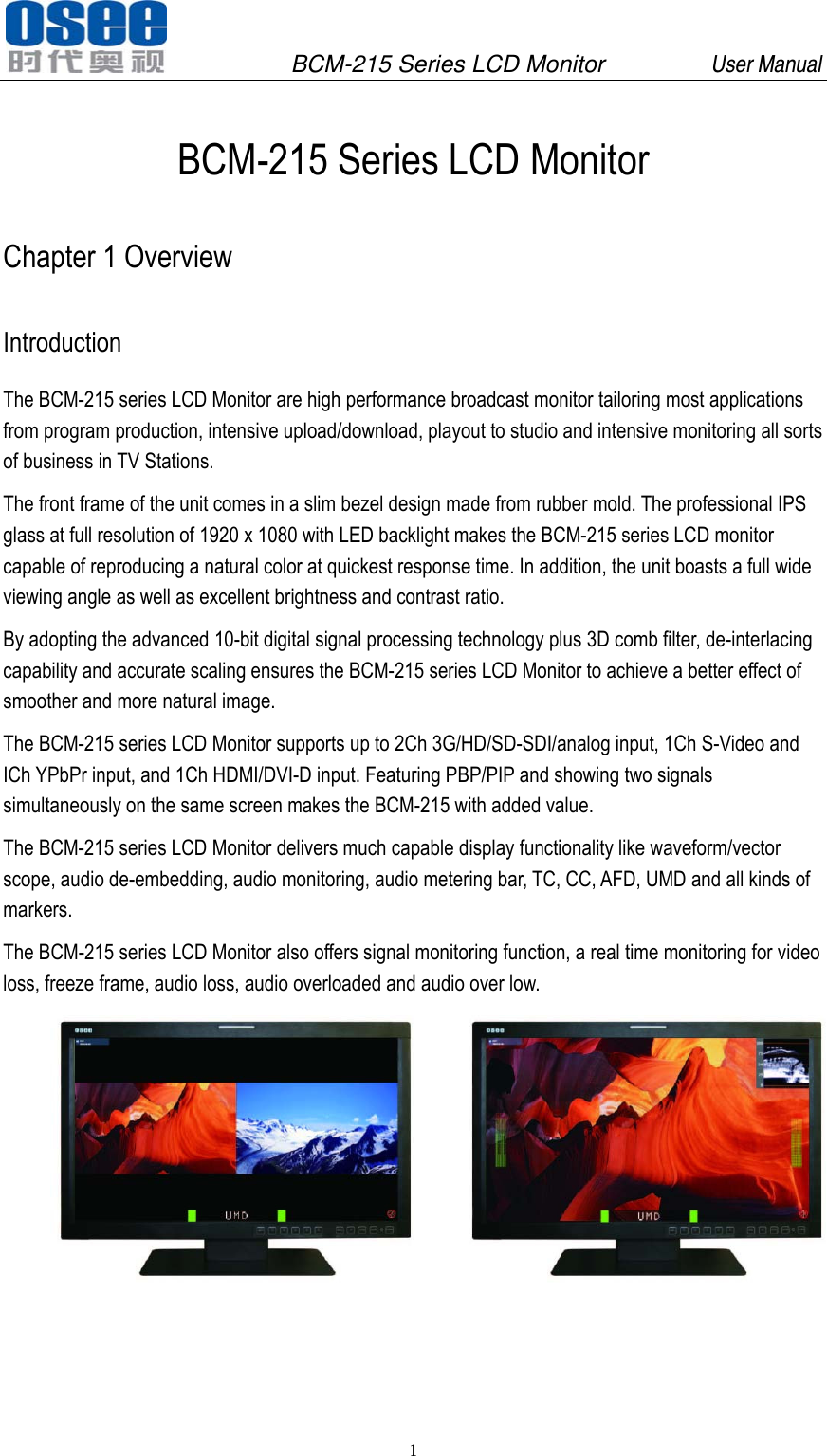
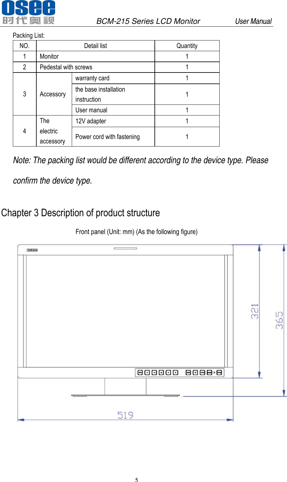
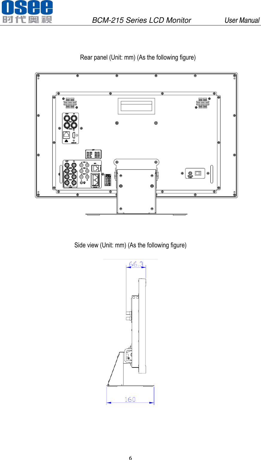
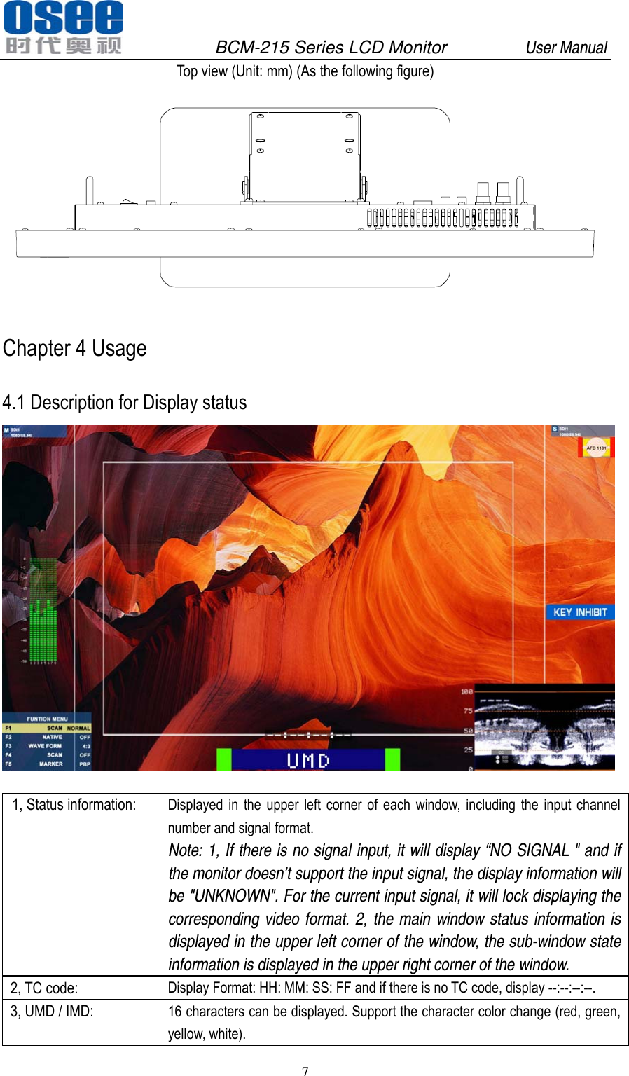
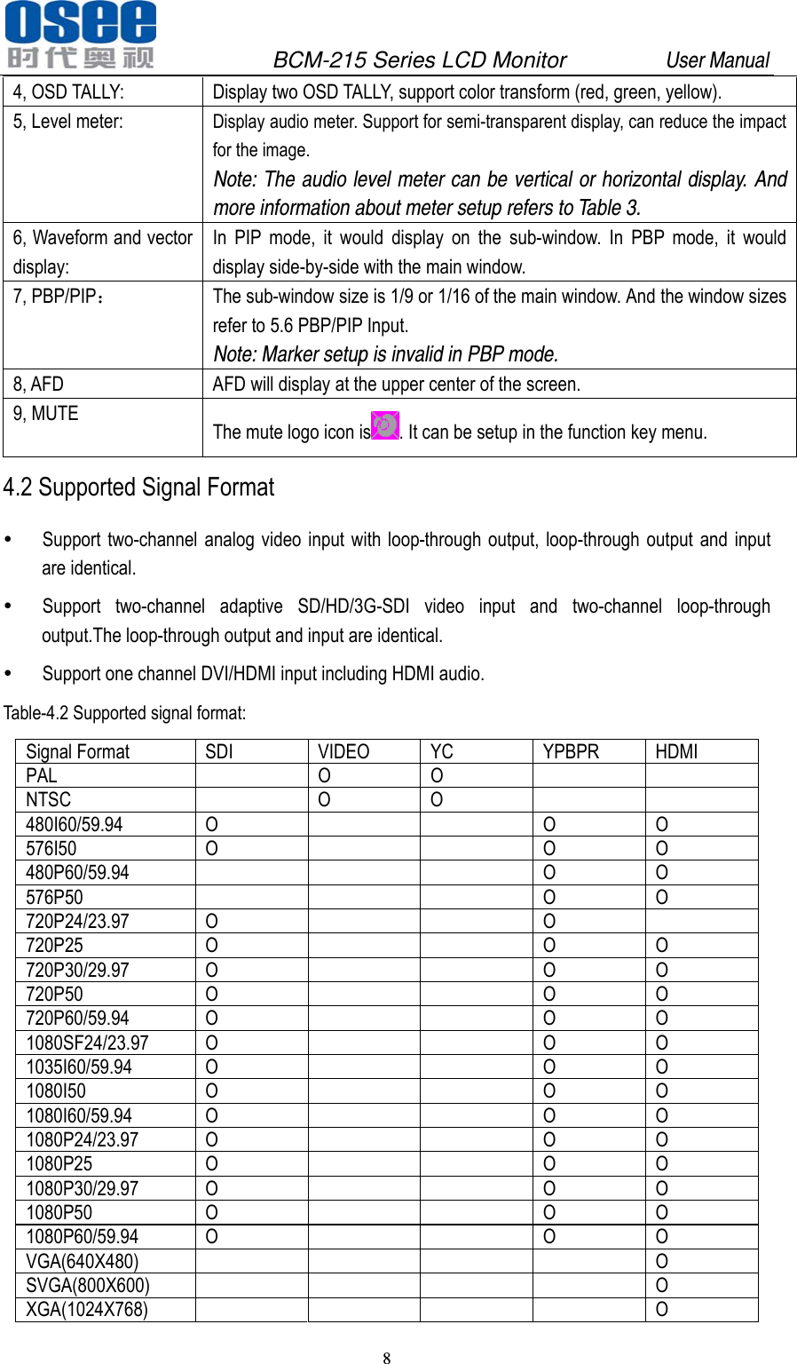
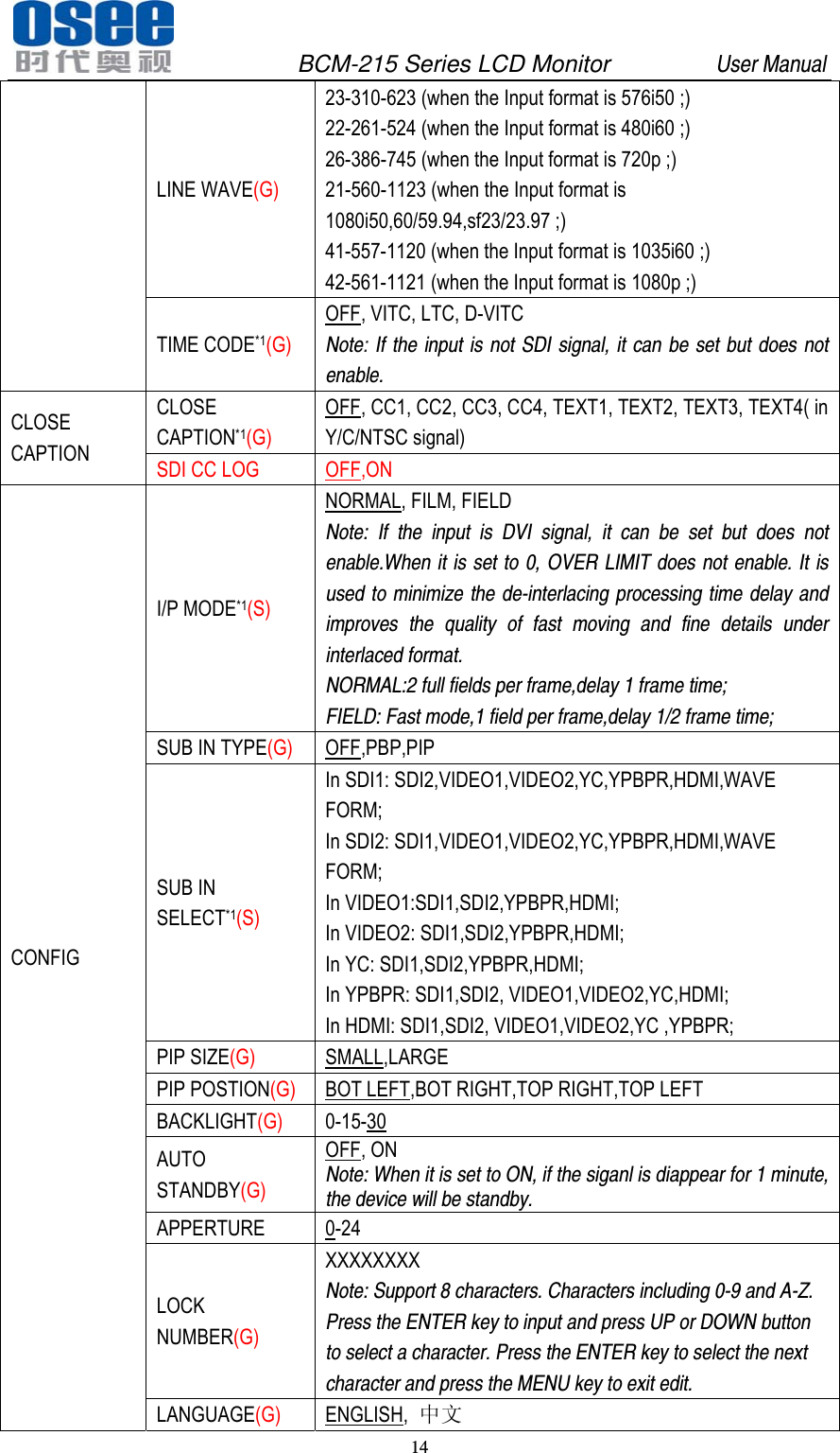
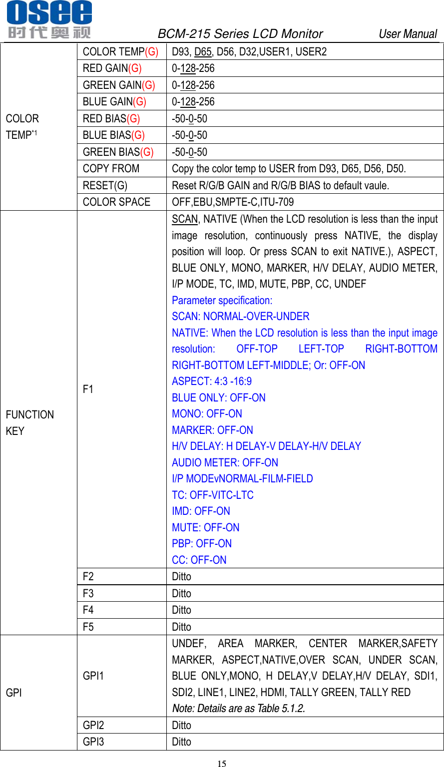
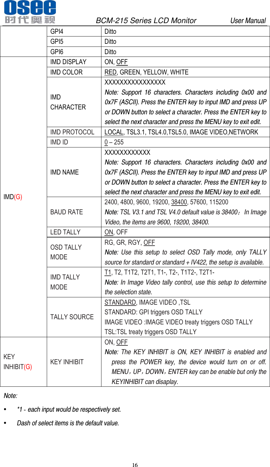
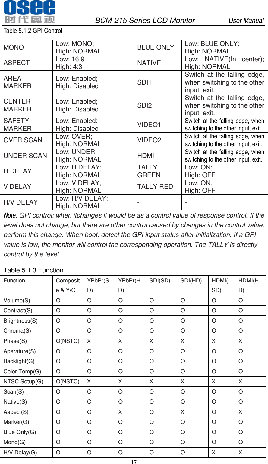
OSEE TECHNOLOGY BCM-215LCDM LCD Monitor User Manual

OSEE TECHNOLOGY CO.,LTD. LCD Monitor Users Manual

Users Manual

     BCM-215 Series LCD Monitor  USER MANUAL
   PRODUCT INFORMATION MODEL: BCM-215 Series LCD Monitor Version: V010001 Modified: March 14th, 2013    COMPANY NAME 北京时代奥视数码技术有限公司 Beijing Osee Digital Technology Ltd.     CONTACT US Address: No.22 Building, No.68 zone, Beiqing Road, Haidian District, Beijing, China Post code: 100094   Tel: 8610 - 62434168 Fax: 8610 - 62434169 Http://www.osee-dig.com E-mail:sales@osee-dig.com
              BCM-215 Series LCD Monitor         User Manual                             About The USER MANUAL  The user manual applies to the following device types:  BCM-215-3HSV  BCM-215-HSV  BCM-215-SV  BCM-215-V The images of BCM-215 monitor are adopted in the following descriptions. Any of the different specifications between the device types are elaborated. Before reading the manual, please confirm the device type.   Note: The specs are subject to change without prior notice!
              BCM-215 Series LCD Monitor         User Manual                         Content Chapter 1 Overview ............................................................................................... 1 Introduction............................................................................................................................................... 1 Feature ..................................................................................................................................................... 2 Chapter 2 Chapter 2 Safety Precaution for Use .................................................... 2 Chapter 3 Unpackaging and installation ................................................................ 4 Chapter 3 Description of product structure ............................................................ 5 Chapter 4 Usage .................................................................................................... 7 4.1 Description for Display status ............................................................................................................. 7 4.2 Supported Signal Format ................................................................................................................... 8 4.3 Interface of rear panel ........................................................................................................................ 9 4.4 Interface of front panel ..................................................................................................................... 10 Chapter 5 Menu Description ................................................................................ 10 5.1 Main menu ........................................................................................................................................ 10 5.2 Status Display .................................................................................................................................. 18 5.3 Function Display ............................................................................................................................... 18 5.4 Adjustment Menu .............................................................................................................................. 19 5.5 Source menu .................................................................................................................................... 19 5.6 PBP/PIP Input .................................................................................................................................. 20 5.7 Factory Reset Menu ......................................................................................................................... 21 Chapter 6 Specification ........................................................................................  21 6.1 Description for Specification ............................................................................................................. 21 6.2 Input signal format ............................................................................................................................ 21 6.3 Specifications ................................................................................................................................... 22 6.4 Input/Output Resolution, Frame Refresh Rate and Color Matrix: ..................................................... 22
              BCM-215 Series LCD Monitor         User Manual 1   BCM-215 Series LCD Monitor Chapter 1 Overview Introduction The BCM-215 series LCD Monitor are high performance broadcast monitor tailoring most applications from program production, intensive upload/download, playout to studio and intensive monitoring all sorts of business in TV Stations. The front frame of the unit comes in a slim bezel design made from rubber mold. The professional IPS glass at full resolution of 1920 x 1080 with LED backlight makes the BCM-215 series LCD monitor capable of reproducing a natural color at quickest response time. In addition, the unit boasts a full wide viewing angle as well as excellent brightness and contrast ratio. By adopting the advanced 10-bit digital signal processing technology plus 3D comb filter, de-interlacing capability and accurate scaling ensures the BCM-215 series LCD Monitor to achieve a better effect of smoother and more natural image. The BCM-215 series LCD Monitor supports up to 2Ch 3G/HD/SD-SDI/analog input, 1Ch S-Video and ICh YPbPr input, and 1Ch HDMI/DVI-D input. Featuring PBP/PIP and showing two signals simultaneously on the same screen makes the BCM-215 with added value. The BCM-215 series LCD Monitor delivers much capable display functionality like waveform/vector scope, audio de-embedding, audio monitoring, audio metering bar, TC, CC, AFD, UMD and all kinds of markers. The BCM-215 series LCD Monitor also offers signal monitoring function, a real time monitoring for video loss, freeze frame, audio loss, audio overloaded and audio over low.
              BCM-215 Series LCD Monitor         User Manual 2   FCC Caution: Any Changes or modifications not expressly approved by the party responsible for compliance could void the user's authority to operate the equipment.       This device complies with part 15 of the FCC Rules.   Operation is subject to the following two conditions: (1) This device may not cause harmful interference, and (2) this device must accept any interference received, including interference that may cause undesired operation.  Note: This equipment has been tested and found to comply with the limits for a Class B digital device, pursuant to part 15 of the FCC Rules. These limits are designed to provide reasonable protection against harmful interference in a residential installation. This equipment generates uses and can radiate radio frequency energy and, if not installed and used in accordance with the instructions, may cause harmful interference to radio communications. However, there is no guaran-tee that interference will not occur in a particular installation. If this equipment does cause harmful interference to radio or television reception, which can be determined by turning the equipment off and on, the user is encouraged to try to correct the interference by one or more of the following measures:   Reorient or relocate the receiving antenna. Increase the separation between the equipment and receiver. Connect the equipment into an outlet on a circuit different from that to which the receiver is connected.  Consult the dealer or an experienced radio/TV technician for help. Feature  Prevailing slim bezel design  Having multi format input including 3G-SDI  Adopting full HD, wide viewing angle IPS glass  Using 10-bit signal processing technology plus advanced conversion technology between the interlacing and the progressive  Featuring PBP and PIP, dual 3G-SDI capable under PBP mode  Supporting waveform/vector scope, audio metering bar, TC, IMD and CC  Supporting varied color temperature, varied scan modes, flexibility in marker setting, Blue Only/Monochrome mode  Signal monitoring, types of alarm include video/audio loss, EDH, freeze frame, black field and audio lever over high/over low Chapter 2 Chapter 2 Safety Precaution for Use   Read and keep these instructions. Heed all warnings. Follow all instructions.  About the Position 1. Do not block any ventilation openings. 2. Do not use this unit near water. 3. Do not expose the unit to rain or moisture.
              BCM-215 Series LCD Monitor         User Manual 3   4. Do not install near any heat sources such as radiators, heat registers, stoves, or other apparatus (including amplifiers) that product heat. 5. A nameplate indicating operating voltage, etc., is located on the rear panel. Install only in accordance with the instructions in the section entitled, “Unpacking and Installation” on page 3. 6. The socket-outlet shall be installed near the equipment and shall be easily accessible.  About the Power-supply Cord    7. Do not defeat the safety purpose of the polarized or grounding-type plug. 8. Do not damage the power cord, place the heavy objects on the power cord, stretch the power cord, or bend the power cord.   9. Protect the power cord from being walked on or pinched, particularly at plugs, convenience receptacles, and the point where they exit from the unit.   10. If the power cord is damaged, turn off the power immediately. It is dangerous to use the unit with a damaged power cord. It may cause fire or electric shock.   11. Unplug this apparatus during lighting storms or when unused for long periods of time. 12. Disconnect the power cord from the AC outlet by grasping the plug, not by pulling the cord. 13. Should any solid object or liquid fall into the cabinet, unplug the unit and have it checked by qualified personnel before operating it any further.
              BCM-215 Series LCD Monitor         User Manual 4    Monitor 14. Do not beat with a hard object or scratch the LCD display. 15. Do not make the freeze picture displaying on the screen time too long, otherwise, it will leave the afterimage on the screen. 16. Install in accordance with the manufacturer’s instructions 17. If the brightness is adjusted to the minimum, then it might be hard to see the display screen. 18. Refer all servicing to qualified service personnel. Servicing will be required under all of the following conditions:  The unit has been exposed to rain or moisture.  Liquid had been spilled or objects have fallen onto the unit.  The unit has been damaged in any way, such as when the power-supply cord or plug is damaged.   The unit does not operate normally. 19. Clean only with dry cloth. 20. Specifications are subject to change without notice.     Chapter 3 Unpackaging and installation Opening the box, please check whether the device has been damaged during transport. Check all the things listed on the packing list are received. If there is any missing, contact your distributors or Beijing Osee Digital Technology Ltd. for it.   We recommend that you should save the packing materials for future needs. 1. Install the pedestal following the iinstallation instructions.   Note: The pedestal and the monitor are packaged separately. 2. Put the monitor on the position you need for installing, and connect the power. Please make sure the place you put is safety. 3. Connect a standard signal lines to the corresponding input port. All BNC connector impedance must be 75Ω. Note: Please use the power adapter supplied to avoid unnecessary trouble. 4. Use the power adapter and cord to connect single-phase three-wire AC power or following the local power supply conditions. Make sure the power cord grounding well. 5. Finally, turn on the power switch, so that the device will be ready for work.
              BCM-215 Series LCD Monitor         User Manual 5   Packing List: NO. Detail list  Quantity 1 Monitor  1 2  Pedestal with screws  1 3 Accessory warranty card  1 the base installation instruction  1 User manual  1 4 The electric accessory 12V adapter  1 Power cord with fastening  1 Note: The packing list would be different according to the device type. Please confirm the device type. Chapter 3 Description of product structure Front panel (Unit: mm) (As the following figure)
              BCM-215 Series LCD Monitor         User Manual 6     Rear panel (Unit: mm) (As the following figure)   Side view (Unit: mm) (As the following figure)
              BCM-215 Series LCD Monitor         User Manual 7   Top view (Unit: mm) (As the following figure)  Chapter 4 Usage   4.1 Description for Display status    1, Status information:  Displayed in the upper left corner of each window, including the input channel number and signal format. Note: 1, If there is no signal input, it will display “NO SIGNAL " and if the monitor doesn’t support the input signal, the display information will be "UNKNOWN". For the current input signal, it will lock displaying the corresponding video format. 2, the main window status information is displayed in the upper left corner of the window, the sub-window state information is displayed in the upper right corner of the window. 2, TC code:  Display Format: HH: MM: SS: FF and if there is no TC code, display --:--:--:--. 3, UMD / IMD:  16 characters can be displayed. Support the character color change (red, green, yellow, white).
              BCM-215 Series LCD Monitor         User Manual 8   4, OSD TALLY:  Display two OSD TALLY, support color transform (red, green, yellow). 5, Level meter:  Display audio meter. Support for semi-transparent display, can reduce the impact for the image. Note: The audio level meter can be vertical or horizontal display. And more information about meter setup refers to Table 3. 6, Waveform and vector display: In PIP mode, it would display on the sub-window. In PBP mode, it would display side-by-side with the main window. 7, PBP/PIP: The sub-window size is 1/9 or 1/16 of the main window. And the window sizes refer to 5.6 PBP/PIP Input. Note: Marker setup is invalid in PBP mode.   8, AFD  AFD will display at the upper center of the screen. 9, MUTE  The mute logo icon is . It can be setup in the function key menu. 4.2 Supported Signal Format  Support two-channel analog video input with loop-through output, loop-through output and input are identical.  Support two-channel adaptive SD/HD/3G-SDI video input and two-channel loop-through output.The loop-through output and input are identical.  Support one channel DVI/HDMI input including HDMI audio. Table-4.2 Supported signal format: Signal Format  SDI  VIDEO  YC  YPBPR  HDMI PAL  O O    NTSC   O O    480I60/59.94 O   O O 576I50 O   O O 480P60/59.94     O O 576P50     O O 720P24/23.97 O   O  720P25 O   O O 720P30/29.97 O   O O 720P50 O   O O 720P60/59.94 O   O O 1080SF24/23.97 O   O O 1035I60/59.94 O   O O 1080I50 O   O O 1080I60/59.94 O   O O 1080P24/23.97 O   O O 1080P25 O   O O 1080P30/29.97 O   O O 1080P50 O   O O 1080P60/59.94 O   O O VGA(640X480)      O SVGA(800X600)      O XGA(1024X768)      O
              BCM-215 Series LCD Monitor         User Manual 9   SXGA(1280X1024)      O WXGA(1360X768)      O WXGA+(1440X900)      O WXGA+(1400X1050)      O UXGA(1600X1200)      O UXGA+(1680X1050)      O WUXGA(1920X1080)      O WUXGA(1920X1200)      O Note:” O” is the Supported signal format. 4.3 Interface of rear panel Note: The specs are subject to change without prior notice.  1,video input/output:   3G/HD/SD SDI signal input / output: BNC x4 (IN/OUT) Composite signal input / output: BNC x4 (IN/OUT) Y/C signal Input / Output: BNC x2 (IN/OUT) YPbPr signal Input / Output: BNC x6 (IN/OUT) HDMI/DVI-D signal Input / Output: HDMI Type-A x1 IN 2,Audio input/output: Audio IN1: Audio signal input Audio IN2: Audio signal input Audio OUT: Audio signal output 3,The control input/output:   GPI port
              BCM-215 Series LCD Monitor         User Manual 10   RJ45 input and output ports Network port for parameter setup, alarm parameter setup, and alarm information read 4,Power input: DC12-19V input, 60W 4.4 Interface of front panel   INPUT: Select the input signal.The source menu would display on the right conner of the window. Each time you press to switch in the following order: SDI 1, SDI 2, VIDEO, YPbPr, and HDMI. The machine retains input selection state. Unused inputs can choose to skip through the menu.  F1 ~ F5: function keys, the function can be set via the FUNCTION menu. Open the FUNCTION menu after the first time, the selected function will remain.  MENU: Enter the main menu item and enter the next sub-menu. Or press this key to backspace to the menu without save.  ▽(DOWN): Select the menu item or select the option of the item.  △(UP): Select the menu item or select the option of the item.  ENTER: Press ENTER in turn to diaplay VOLUME, BRIGHTNESS, CONTRAST, CHROMA, APPERTURE menu. And in main menu, click the button to enter the next level menu, or press the botton to save the setup and backspace the menu.  POWER: Power switch. Chapter 5 Menu Description 5.1 Main menu It displays as following fig 5.1.1 by pressing the MENU button.
              BCM-215 Series LCD Monitor         User Manual 11    Fig 5.1.1  Fig5.1.2 1 Main menu NAME The main menu item which is selected will be display.  2 Menu items  Press MENU key, the menu will display in the screen.    Press ENTER key to enter the item selected and press the ENTER ket again, the setup will be saved.  Press MENU key to exit the menu and don’t save the setup.  3 Sub-menu items    Press UP/DOWN to switch the items.    Press MENU key to backspace the main menu items.    Press ENTER key to enter the sub-menu items which is selected.   Note:  1. When the menu is enabled, if the signal changes, the menu will refresh the current contents of the menu.  2. Press MENU key and if there is no operation within 60s, the menu will automatically disappear. 1 2 3
              BCM-215 Series LCD Monitor         User Manual 12   3. The main menu display in the upper left corner of the screen. 4. The background of selected menu item color changes to yellow. 5. The items can not be adjusted in the submenu would be gray. Details are as follows: MAIN MENU  SUB-MENU ITEMS STATUS  Status messages INPUT SELECT(G) SDI1 ON, OFF SDI2 ON, OFF LINE1 ON, OFF LINE2  CVBS, Y/C, YPbPr, OFF Note: The BCM215 monitor support only. HDMI HDMI, DVI-D, OFF NTSC SETUP*2 0, 7.5 NTSC PHASE  -50-0-50 MARKER*1(G) MARKER  OFF, ON Note: If you selected NATIVE, the MARKER will be disabled.   AREA MARKER  OFF, 4:3, 15:9, 14:9, 13:9, 1.85:1, 2.35:1( in 16:9mode); OFF, 16:9 CENTER MARKER  OFF, ON SAFETY MARKER  OFF, 80%, 85%, 88%, 90%, 93%, 95%, 100% MARKER LEVEL 1, 2, 3 1: amount to 50% white level 2: amount to 75% white level 3: amount to 100% white level MARKER MAT  OFF, HALF, BLACK ADUIO*1 AUDIO SOURCE(S) AUDIO1, AUDIO2, UNDEF (VIDEO1 in) AUDIO1, AUDIO2, UNDEF    (VIDEO2/ YC/YPBPR in) AUDIO1, AUDIO2, EMBEDDED, UNDEF (SDI1/SDI2/HDMI in)  Note: UNDEFINED is simple spelled as undef. SPEAK OUT L(S) EBD CH1, EBD CH2, EBD CH3, EBD CH4, EBD CH5, EBD CH6, EBD CH7, EBD CH8, EBD CH9, EBD CH10, EBD CH11, EBD CH12, EBD CH13, EBD CH14, EBD CH15, EBD CH16 Note: When the AUDIO SOURCE is EMBEDDED,the inputwould be SDI. When the input is HDMI, this item is disabled. When the AUDIO SOURCE is AUDIO1, AUDIO2 orUNDEF, this item is disabled.
              BCM-215 Series LCD Monitor         User Manual 13   SPEAK OUT R(S) EBD CH1, EBD CH2, EBD CH3, EBD CH4, EBD CH5, EBD CH6, EBD CH7, EBD CH8, EBD CH9, EBD CH10, EBD CH11, EBD CH12, EBD CH13, EBD CH14, EBD CH15, EBD CH16 Note: When the AUDIO SOURCE is EMBEDDED,the inputwould be SDI. When the input is HDMI, this item is disabled. When the AUDIO SOURCE is AUDIO1, AUDIO2 orUNDEF, this item is disabled. AUDIO METER(G) OFF, ON MTER SELECT(G)  CH1-2,G1,G2,G3,G4,G1+2,G1+3,G1+4,G2+3,G2+4,G3+4,G1-4METER DIS MODE  SIMPLE,INTACT METER POSITION TOP,BOTTOM,(when the METER DIRECTION is HORIZONTAL); BOT LEFT,BOT RIGHT,TOP RIGHT,TOP LEFT(when the METER DIRECTION is VERTICAL); METER DISPALY MODE MODE1,MODE2,MODE3 Note: The MODE1 is the Simple meter mode. The MODE2 is the meter with channel name and the MODE3 is the meter with channle name and level vaule. REF LEVEL(G)  -20dB, -18dB OVER LEVEL(G)  -10dB, -8dB, -6dB, -4dB, -2dB DISPLAY STATUS DISPLAY(G) OFF, AUTO, ON Note: When the setuo is AUTO, the signal status display for 15s and then disappears when it changed. AFD DISPLAY(G) OFF, ON Note: When it is setted as ON, it would display follow the STATUS or be OFF. If the input is not SDI signal, it can be set but does not enable. When STATUS is set to AUTO, and AFD is ON, either STATUS or AFD changes, it will show the STATUS and AFD information. WAVE FORM MODE*1(G) WAVEFORM,VECTOR 75,VECTOR 100,LINE WAVE Note: If the input is not SDI signal, it can be set but does not enable. WAVE OVER(G) LIMIT*1(G) 50-100 Note: If the input is not SDI signal, it can be set but does not enable.When it is set to 100, OVER LIMIT does not enable. WAVE UNDER LIMIT*1(G) 0-50 Note: If the input is not SDI signal, it can be set but does not enable.When it is set to 0, OVER LIMIT does not enable.
              BCM-215 Series LCD Monitor         User Manual 14   LINE WAVE(G) 23-310-623 (when the Input format is 576i50 ;) 22-261-524 (when the Input format is 480i60 ;) 26-386-745 (when the Input format is 720p ;) 21-560-1123 (when the Input format is 1080i50,60/59.94,sf23/23.97 ;) 41-557-1120 (when the Input format is 1035i60 ;) 42-561-1121 (when the Input format is 1080p ;) TIME CODE*1(G) OFF, VITC, LTC, D-VITC Note: If the input is not SDI signal, it can be set but does not enable. CLOSE CAPTION CLOSE CAPTION*1(G) OFF, CC1, CC2, CC3, CC4, TEXT1, TEXT2, TEXT3, TEXT4( in Y/C/NTSC signal) SDI CC LOG  OFF,ON CONFIG I/P MODE*1(S) NORMAL, FILM, FIELD Note: If the input is DVI signal, it can be set but does not enable.When it is set to 0, OVER LIMIT does not enable. It is used to minimize the de-interlacing processing time delay and improves the quality of fast moving and fine details under interlaced format. NORMAL:2 full fields per frame,delay 1 frame time; FIELD: Fast mode,1 field per frame,delay 1/2 frame time; SUB IN TYPE(G) OFF,PBP,PIP SUB IN SELECT*1(S) In SDI1: SDI2,VIDEO1,VIDEO2,YC,YPBPR,HDMI,WAVE FORM; In SDI2: SDI1,VIDEO1,VIDEO2,YC,YPBPR,HDMI,WAVE FORM; In VIDEO1:SDI1,SDI2,YPBPR,HDMI; In VIDEO2: SDI1,SDI2,YPBPR,HDMI; In YC: SDI1,SDI2,YPBPR,HDMI; In YPBPR: SDI1,SDI2, VIDEO1,VIDEO2,YC,HDMI; In HDMI: SDI1,SDI2, VIDEO1,VIDEO2,YC ,YPBPR; PIP SIZE(G) SMALL,LARGE PIP POSTION(G) BOT LEFT,BOT RIGHT,TOP RIGHT,TOP LEFT BACKLIGHT(G) 0-15-30 AUTO STANDBY(G) OFF, ON Note: When it is set to ON, if the siganl is diappear for 1 minute, the device will be standby. APPERTURE 0-24 LOCK NUMBER(G) XXXXXXXX Note: Support 8 characters. Characters including 0-9 and A-Z. Press the ENTER key to input and press UP or DOWN button to select a character. Press the ENTER key to select the next character and press the MENU key to exit edit. LANGUAGE(G) ENGLISH,  中文
              BCM-215 Series LCD Monitor         User Manual 15   COLOR TEMP*1 COLOR TEMP(G) D93, D65, D56, D32,USER1, USER2 RED GAIN(G) 0-128-256 GREEN GAIN(G) 0-128-256 BLUE GAIN(G) 0-128-256 RED BIAS(G) -50-0-50 BLUE BIAS(G) -50-0-50 GREEN BIAS(G) -50-0-50 COPY FROM  Copy the color temp to USER from D93, D65, D56, D50. RESET(G)  Reset R/G/B GAIN and R/G/B BIAS to default vaule. COLOR SPACE  OFF,EBU,SMPTE-C,ITU-709 FUNCTION KEY F1 SCAN, NATIVE (When the LCD resolution is less than the input image resolution, continuously press NATIVE, the display position will loop. Or press SCAN to exit NATIVE.), ASPECT, BLUE ONLY, MONO, MARKER, H/V DELAY, AUDIO METER, I/P MODE, TC, IMD, MUTE, PBP, CC, UNDEF Parameter specification: SCAN: NORMAL-OVER-UNDER NATIVE: When the LCD resolution is less than the input image resolution: OFF-TOP LEFT-TOP RIGHT-BOTTOM RIGHT-BOTTOM LEFT-MIDDLE; Or: OFF-ON ASPECT: 4:3 -16:9 BLUE ONLY: OFF-ON MONO: OFF-ON MARKER: OFF-ON H/V DELAY: H DELAY-V DELAY-H/V DELAY AUDIO METER: OFF-ON I/P MODEvNORMAL-FILM-FIELD TC: OFF-VITC-LTC IMD: OFF-ON MUTE: OFF-ON PBP: OFF-ON CC: OFF-ON F2 Ditto F3 Ditto F4 Ditto F5 Ditto GPI GPI1 UNDEF, AREA MARKER, CENTER MARKER,SAFETY MARKER, ASPECT,NATIVE,OVER SCAN, UNDER SCAN, BLUE ONLY,MONO, H DELAY,V DELAY,H/V DELAY, SDI1, SDI2, LINE1, LINE2, HDMI, TALLY GREEN, TALLY RED Note: Details are as Table 5.1.2. GPI2 Ditto GPI3 Ditto
              BCM-215 Series LCD Monitor         User Manual 16   GPI4 Ditto GPI5 Ditto GPI6 Ditto IMD(G) IMD DISPLAY  ON, OFF IMD COLOR  RED, GREEN, YELLOW, WHITE IMD CHARACTER XXXXXXXXXXXXXXXX Note:  Support 16 characters. Characters including 0x00 and 0x7F (ASCII). Press the ENTER key to input IMD and press UP or DOWN button to select a character. Press the ENTER key to select the next character and press the MENU key to exit edit.  IMD PROTOCOL  LOCAL, TSL3.1, TSL4.0,TSL5.0, IMAGE VIDEO,NETWORK IMD ID  0 – 255 IMD NAME XXXXXXXXXXXX Note: Support 16 characters. Characters including 0x00 and 0x7F (ASCII). Press the ENTER key to input IMD and press UP or DOWN button to select a character. Press the ENTER key to select the next character and press the MENU key to exit edit. BAUD RATE 2400, 4800, 9600, 19200, 38400, 57600, 115200 Note: TSL V3.1 and TSL V4.0 default value is 38400;In Image Video, the items are 9600, 19200, 38400. LED TALLY  ON, OFF OSD TALLY MODE RG, GR, RGY, OFF Note: Use this setup to select OSD Tally mode, only TALLY source for standard or standard + IV422, the setup is available. IMD TALLY MODE T1, T2, T1T2, T2T1, T1-, T2-, T1T2-, T2T1- Note: In Image Video tally control, use this setup to determine the selection state. TALLY SOURCE STANDARD, IMAGE VIDEO ,TSL STANDARD: GPI triggers OSD TALLY IMAGE VIDEO :IMAGE VIDEO treaty triggers OSD TALLY TSL:TSL treaty triggers OSD TALLY KEY INHIBIT(G) KEY INHIBIT ON, OFF Note: The KEY INHIBIT is ON, KEY INHIBIT is enabled and press the POWER key, the device would turn on or off. MENU,UP,DOWN,ENTER key can be enable but only the KEYINHIBIT can disaplay. Note:   *1 - each input would be respectively set.    Dash of select items is the default value.
              BCM-215 Series LCD Monitor         User Manual 17   Table 5.1.2 GPI Control MONO  Low: MONO; High: NORMAL  BLUE ONLY  Low: BLUE ONLY; High: NORMAL ASPECT  Low: 16:9 High: 4:3  NATIVE  Low: NATIVE(In center); High: NORMAL AREA MARKER  Low: Enabled; High: Disabled  SDI1  Switch at the falling edge, when switching to the other input, exit. CENTER MARKER  Low: Enabled; High: Disabled  SDI2  Switch at the falling edge, when switching to the other input, exit. SAFETY MARKER  Low: Enabled; High: Disabled  VIDEO1  Switch at the falling edge, when switching to the other input, exit. OVER SCAN  Low: OVER; High: NORMAL  VIDEO2  Switch at the falling edge, when switching to the other input, exit. UNDER SCAN  Low: UNDER; High: NORMAL  HDMI  Switch at the falling edge, when switching to the other input, exit. H DELAY  Low: H DELAY; High: NORMAL  TALLY GREEN  Low: ON; High: OFF V DELAY  Low: V DELAY; High: NORMAL  TALLY RED  Low: ON; High: OFF H/V DELAY  Low: H/V DELAY; High: NORMAL  - - Note: GPI control: when itchanges it would be as a control value of response control. If the level does not change, but there are other control caused by changes in the control value, perform this change. When boot, detect the GPI input status after initialization. If a GPI value is low, the monitor will control the corresponding operation. The TALLY is directly control by the level.  Table 5.1.3 Function Function Composite & Y/C YPbPr(SD) YPbPr(HD) SDI(SD) SDI(HD) HDMI(SD) HDMI(HD) Volume(S) O O O O O O O Contrast(S) O O O O O O O Brightness(S) O O O O O O O Chroma(S) O O O O O O O Phase(S)  O(NSTC) X X X X X X Aperature(S) O O O O O O O Backlight(G) O O O O O O O Color Temp(G) O O O O O O O NTSC Setup(G) O(NSTC) X X X X X X Scan(S)  O O O O O O O Native(S)  O O O O O O O Aapect(S) O O X O X O X Marker(G) O O O O O O O Blue Only(G) O O O O O O O Mono(G)  O O O O O O O H/V Delay(G) O O O O O X X
              BCM-215 Series LCD Monitor         User Manual 18   Auto Standby(G) O O O O O O O I/P MODE(S) O O O O O O O WFM/VECT(G) X X X O O X X Audio Meter(G) O O O O O O O TC(G)  X X X O O X X IMD(G)  O O O O O O O Mute(G)  O O O O O O O CC(S) O(NSTC) X X O O(HD) X X SubWin (S) O O O O O O O Note: "G" represents the channel is irrelevant; "S" indicates that set associated the channel. Siganl channel such as SDI1,SDI2,VIDEO1,VIDEO2,YC,YPBPR,HDMI. 5.2 Status Display Press MENU, it will display the status information as following. If there is no operation for 10 seconds, the menu would disappear. INPUT       SDI1(or others) FORMAT      1080I50(DVI: 1024X768@60, etc.) COLOR TEMP     D65 SCAN MODE     NORMAL I/P MODE     NORMAL MODEL      BCM2150(according to the monitor) SERIAL NUMBER    XXXXXXXXXXXXXXXX IP ADDRESS     168.192.1.86          COLOR VERSION              65535 – 255 – 255 . 65535 5.3 Function Display In all mode, the function menus are displayed in the lower left corner of the screen, with blue background and white font. The background color of the currently selected item changes into yellow. If there is no operation for 10 seconds, the menu would disappear.
              BCM-215 Series LCD Monitor         User Manual 19    Detailed information refers to main menu table. 5.4 Adjustment Menu When it is not in main menu mode, press ENTER to disaplay VOLUME/BRIGHTNESS/CONTRAST/CHROMA menu items. If there is no operation for 10 seconds, the menu would disappear.  5.5 Source menu Source menu displays in the upper-right corner of the screen, with blue background and white font. The background color of the currently selected item changes into yellow.
              BCM-215 Series LCD Monitor         User Manual 20   In the menu, the sourse which can not be selected is still display with gray point. If there is no operation for 10 seconds, the menu would disappear.  5.6 PBP/PIP Input Table 5.6.1 PBP/PIP Input source Sub Main SDI1 SDI2 VIDEO1 VIDEO2 YC YPBPR HDMI WAVE FORM SDI1  X  O  O O O O O O SDI2  O  X  O O O O O O VIDEO1 O  O X X X O O X VIDEO2 O  O X X X O O X YC O O X X X O O X YPBPR  O  O  O O O X O X       HDMI  O  O  O  O  O  O  X  X  Table 5.6.2 PBP screen size Ratio Signal 4:3 16:9 SD  PanelWidth/2 X (PanelWidth/2)*3/4  PanelWidth/2 X PanelHeight/2 HD X PanelWidth/2 X PanelHeight/2 WAVEFORM PanelHeight/2 X PanelHeight/2  PanelHeight/2 X PanelHeight/2
              BCM-215 Series LCD Monitor         User Manual 21   Table 5.6.2 PIP screen size Ratio Signal 4:3 16:9 SD SMALL  (PanelWidth/4)*3/4 X PanelHeight/4  PanelWidth/4 X PanelHeight/4 HD SMALL  X  PanelWidth/4 X PanelHeight/4 SD LARGE  (PanelWidth/4)*3/4 X PanelHeight/4  PanelWidth/3 X PanelHeight/3 HD LARGE  X  PanelWidth/3 X PanelHeight/3 WAVEFORM SMALL  PanelHeight/4 X PanelHeight/4  PanelHeight/4 X PanelHeight/4 5.7 Factory Reset Menu Press INPUT key and F2 at the same for 3 secounds,and the factory reset menu would be displayed。Select YES or NO by UP and DOWN keys and press ENTER to restore factory settings. Press MENU to disable the factory reset menu. Chapter 6 Specification 6.1 Description for Specification LCD Dimension 21.5” Screen Scale  16:9   Resolution  1920 (H) x 1080 (V) Color Depth 16.7M, 24-bit Viewing Angle 178°(H/V) Brightness 250 cd/m^2 Contrast Ratio  1000:1 6.2 Input signal format Analog Composite:  PAL, NTSC SD-SDI:  480i、576i HD-SDI:  1080i50、1080i 59.94、 1080i 60, 720p50、720p 59.94、720p 60, 1035i59.94、1035i 60 3G-SDI:  1080p50、1080p 59.94、1080p 60
              BCM-215 Series LCD Monitor         User Manual 22   6.3 Specifications CVBS Input/ Output: Signal Type  NTSC, PAL Signal Amplitude  1Vp-p+/-3dB Impedance 75 ohms Return Loss  >40 dB 到5 MHz DC Offset  0V±0.05 V Frequency Response  ±0.2 dB to 5 MHz Differential Gain  <1% Differential Phase  <1.5° 3G-SDI /HD-SDI /SDI-SDI Input/ Output: Signal Type  SMPTE 424M, SMPTE 292M, SMPTE 259M, SMPTE 297M Connector  BNC per IEC 169-8 Impedance 75 ohms Return Loss  >18 dB 5 to 270 MHz >15 dB 270 MHz to 1.5 GHz >10 dB up to 3 GHz Maximum Signal Level  800 mV pk-pk 10% Signal Amplitude  800 mV pk-pk 10% DC Offset  0 V ±0.5 V Overshoot <10% Total Jitter  <0.2 UI Rise and Fall Time  <700 ps for SD <270 ps for 1.5 Gb/s HD <135 ps for 3 Gb/s HD Extinction Ratio  >8 Back Reflection  <-14 dB 6.4 Input/Output Resolution, Frame Refresh Rate and Color Matrix:  OVERSCAN  NATIVE  FULL NORMAL Frame Rate Color Matrix INPUT OUTPUT INPUT OUTPUT INPUT ALL OUTPUT NORMAL NTSC 684X462 1366X768 1024X768 720X487 720X487 720X487  1366X768 1024X768 60 601 PAL 684X548 1366X768 1024X768 720X576 720X576 720X576  1366X768, 1024X768 50 601 SECAM 684X548 1366X768 1024X768 720X576 720X576 720X576  1366X768, 1024X768 50 601 NTCS-4.43 684X462 1366X768 1024X768 720X487 720X487 720X487  1366X768, 1024X768 60 601 PAL-M 684X462 1366X768 1024X768 720X487 720X487 720X487  1366X768, 1024X768 60 601 480I60 684X462 1366X768 1024X768 720X487 720X487 720X487  1366X768, 1024X768 60 601/709
              BCM-215 Series LCD Monitor         User Manual 23   576I50 684X548 1366X768 1024X768 720X576 720X576 720X576  1366X768, 1024X768 50 601 480P60 684X462 1366X768 1024X768 720X487 720X487 720X487  1366X768, 1024X768 60 601/709 576P50 684X548 1366X768 1024X768 720X576 720X576 720X576  1366X768, 1024X768 50  601 720P24 1216X684 1366X768, 1280x720 1280x720 1280x720  1366X768,  48  709 720P25 1216X684 1366X768, 1280x720 1280x720 1280x720  1366X768,  50  709 720P30 1216X684 1366X768, 1280x720 1280x720 1280x720  1366X768,  30  709 720P50 1216X684 1366X768, 1280x720 1280x720 1280x720  1366X768,  50  709 720P60 1216X684 1366X768, 1280x720 1280x720 1280x720  1366X768,  60  709 1035I60 1824X984 1366X768, 1920X1035 1920X1035 1920X1035 1366X768, 60  709 1080I60 1824X1026 1366X768, 1920X1080 1920X1080 1920X1080 1366X768, 60  709 1080I50 1824X1026 1366X768, 1920X1080 1920X1080 1920X1080 1366X768, 50  709 1080P24 1824X1026 1366X768, 1920X1080 1920X1080 1920X1080 1366X768, 48  709 1080P25 1824X1026 1366X768, 1920X1080 1920X1080 1920X1080 1366X768, 50  709 1080P30 1824X1026 1366X768, 1920X1080 1920X1080 1920X1080 1366X768, 60  709 1080P50 1824X1026 1366X768, 1920X1080 1920X1080 1920X1080 1366X768, 50  709 1080P60 1824X1026 1366X768, 1920X1080 1920X1080 1920X1080 1366X768, 60  709 1080SF24 1824X1026 1366X768, 1920X1080 1920X1080 1920X1080 1366X768, 48  709 VGA      640X480 1366X768 60-75  SVGA      800X600 1366X768 60-75  XGA      1024x768 1366X768 60-75  SXGA      1280x1024 1366X768 60-75   UXGA      1600x1200 1366X768 60   WXGA      1360X768 1360X768 60   WUXGA      1920x1200 1366X768 60    *Don’t display all OSD except FORMAT when SCAN is NATIVE. *Don’t display MARKER when SCAN is NATIVE.  Note: The specs are subject to change without prior notice!

Navigation menu