OSEE TECHNOLOGY XCM240LCDM LCD Monitor User Manual
OSEE TECHNOLOGY CO.,LTD. LCD Monitor Users Manual
UserManual.wiki
>
OSEE TECHNOLOGY
>
XCM240LCDM User Manual
Users Manual
Navigation menu
Upload a User Manual
Namespaces
Wiki Guide
HTML
PDF
Info
Views
User Manual
Discussion / Help
Navigation


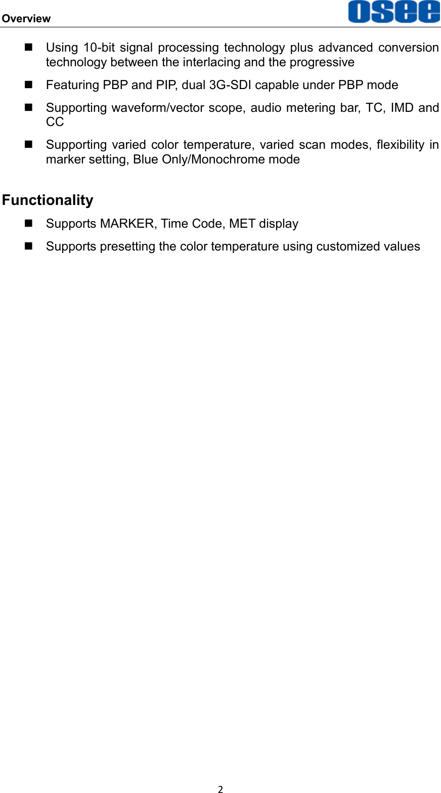


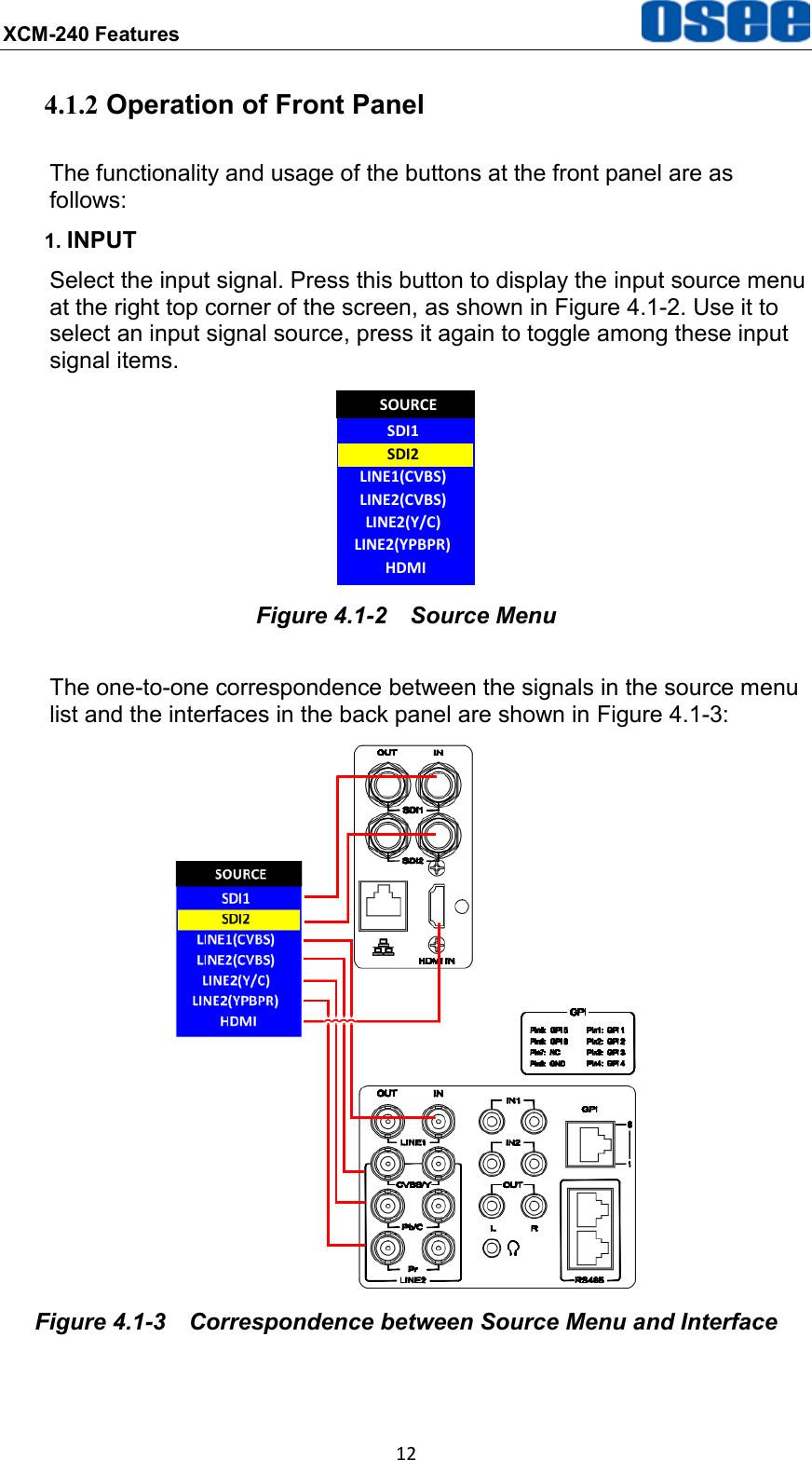
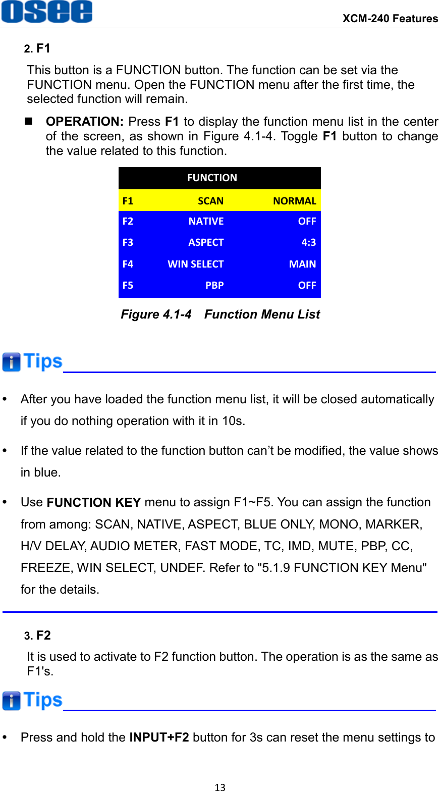
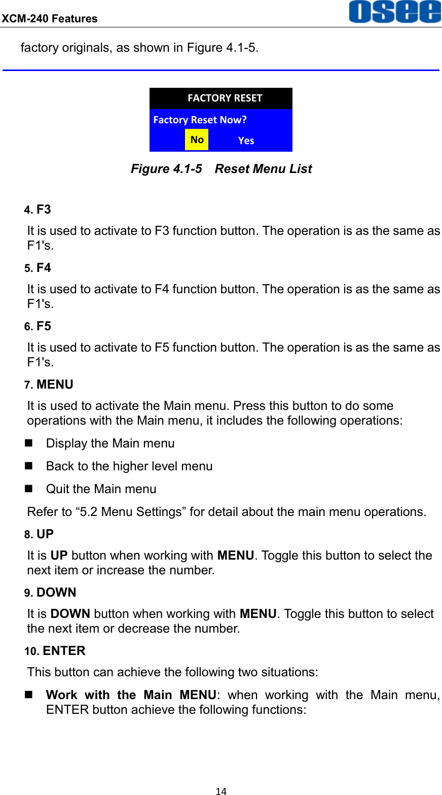
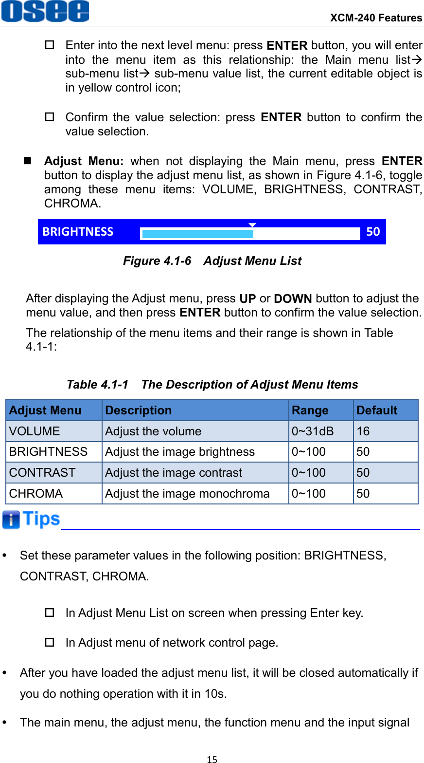
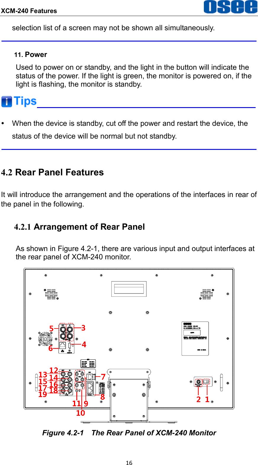
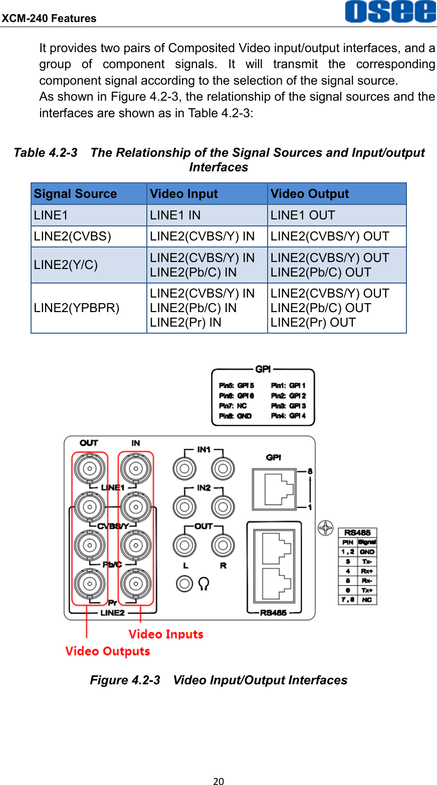
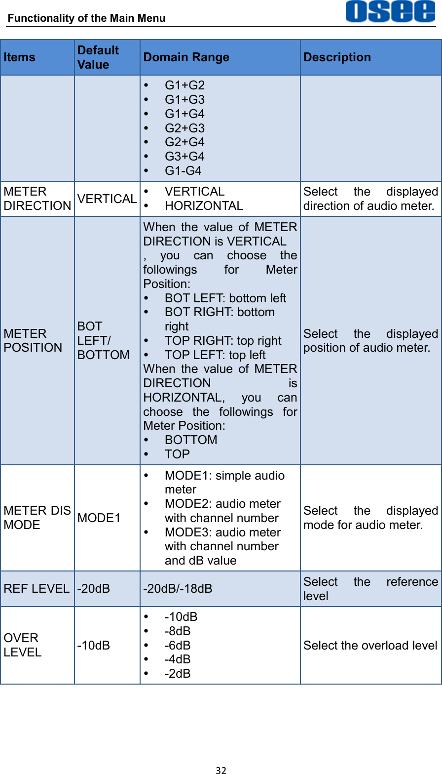
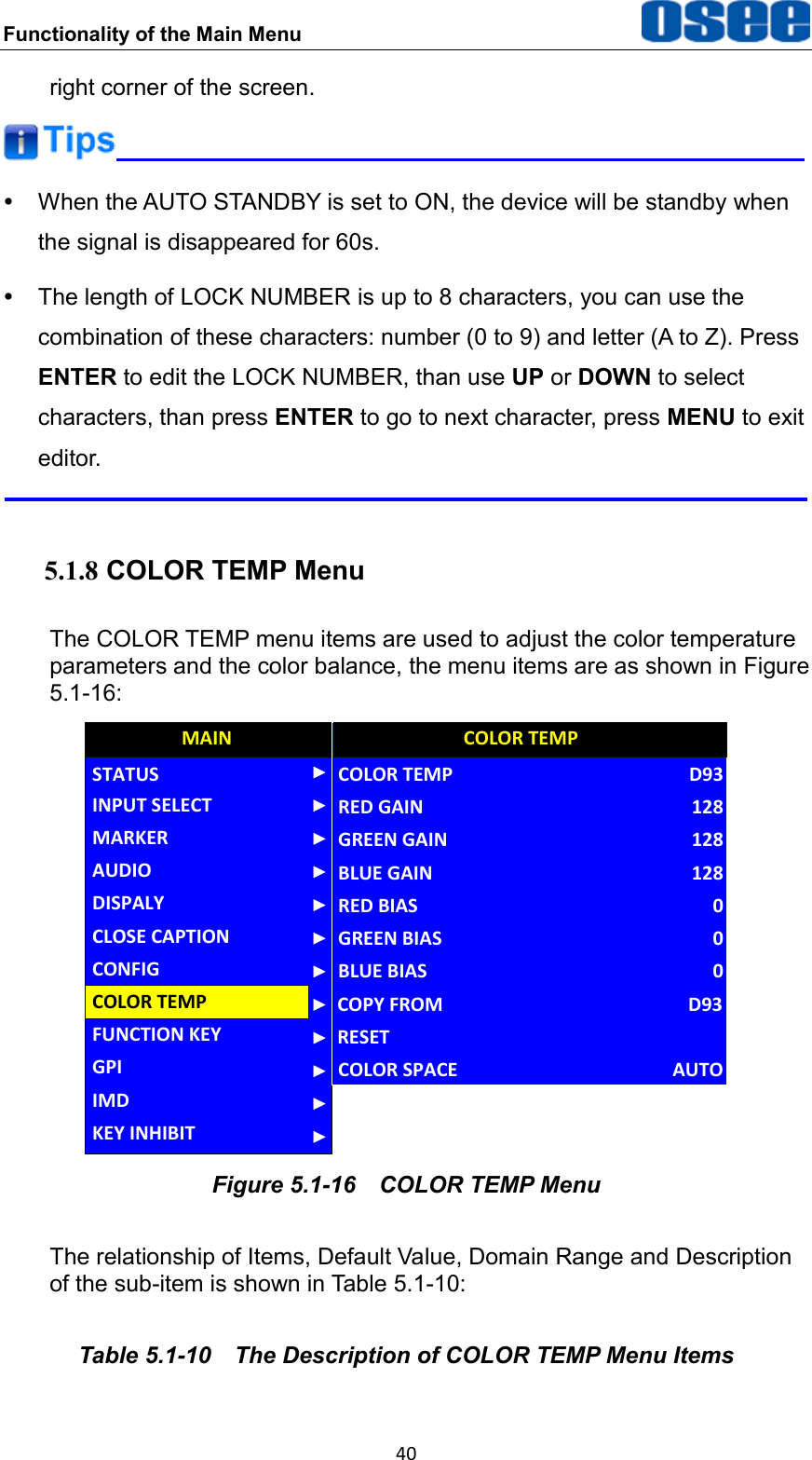
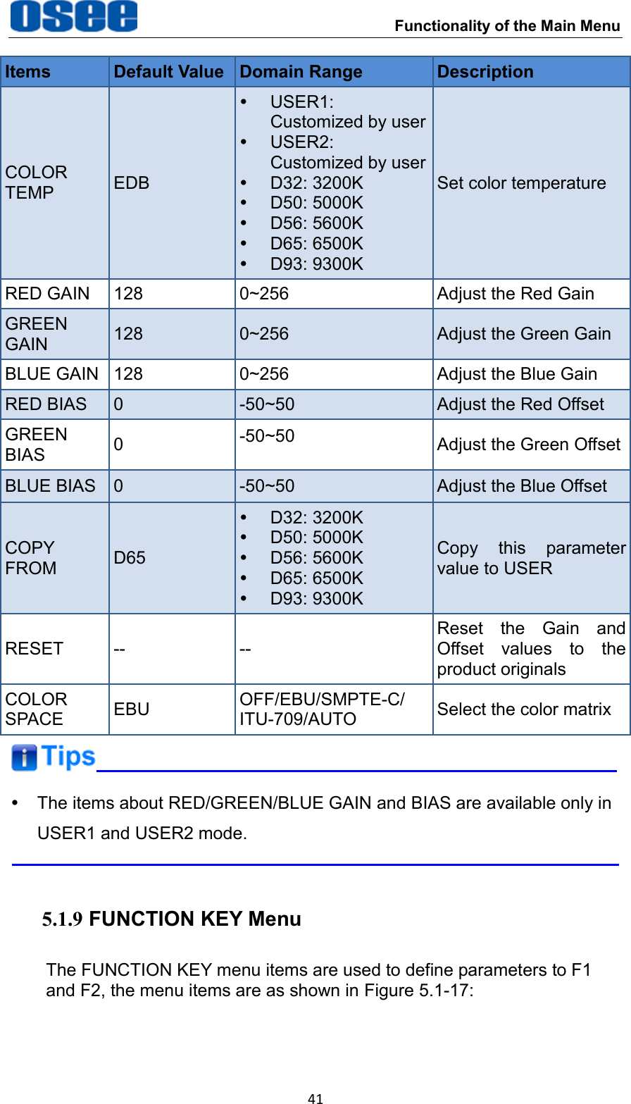
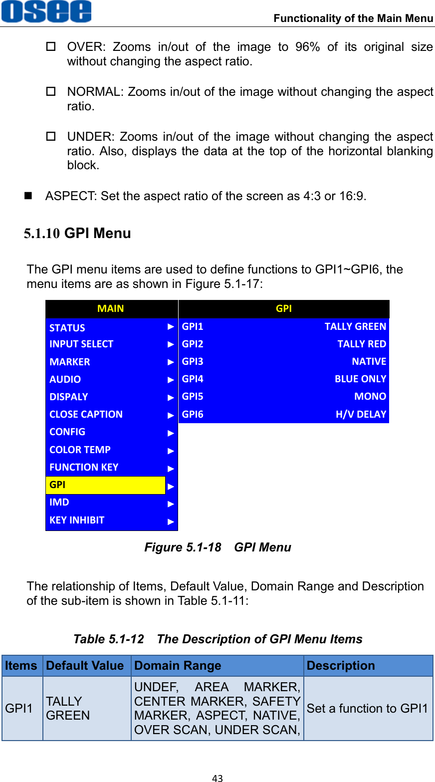
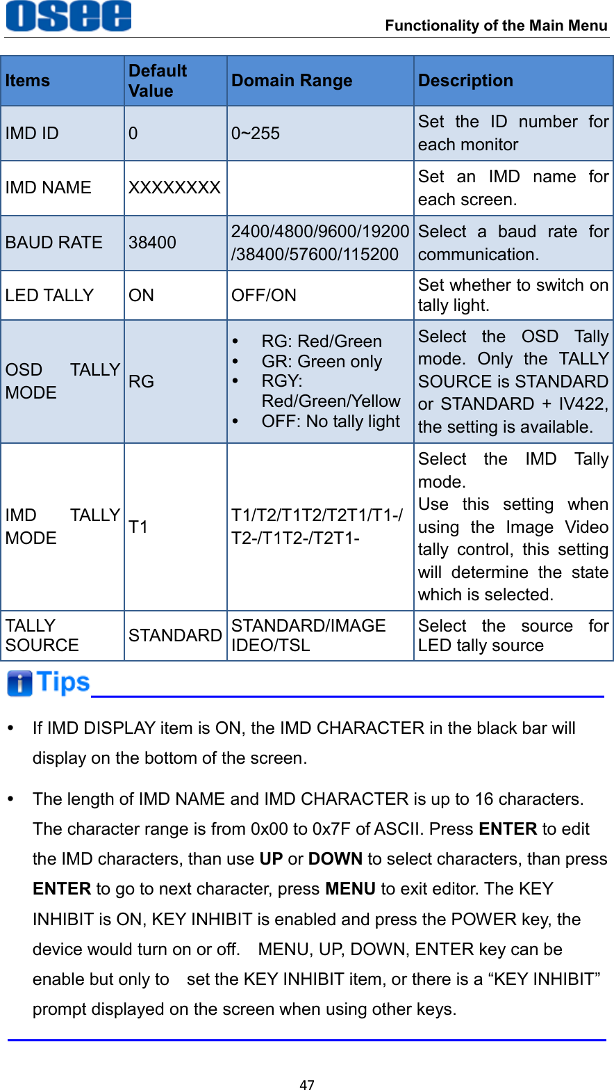
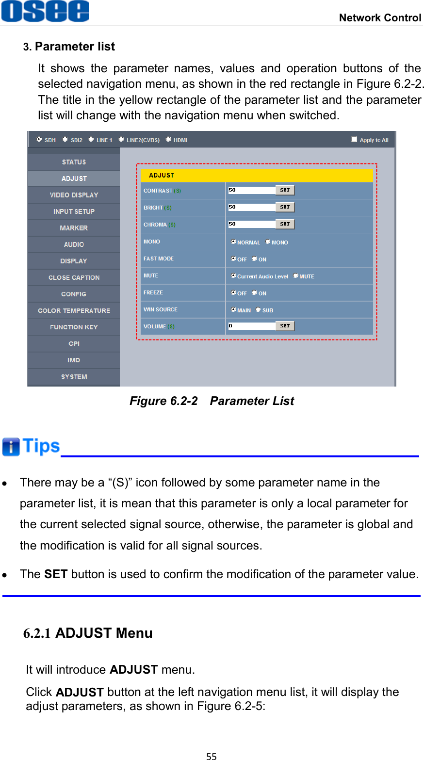
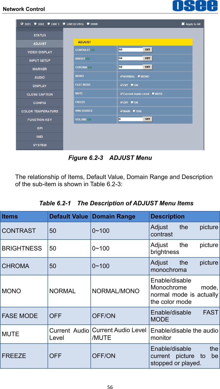
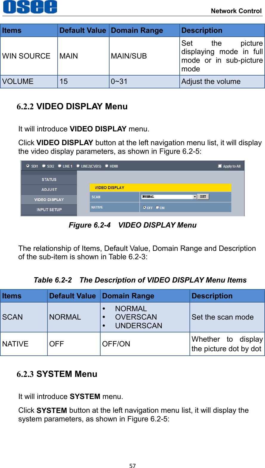
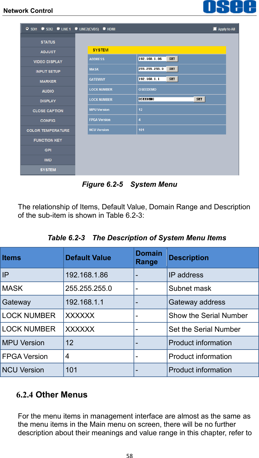
![Functionality of the Main Menu 42 AUDIOGPIMAINFUNCTION KEYCONFIGCOLOR TEMPCLOSE CAPTIONDISPALYMARKERINPUT SELECTSTATUSIMDKEY INHIBITF1F2FUNCTION KEYSCANNATIVEF3F4ASPECTOFFF5 OFF Figure 5.1-17 FUNCTION KEY Menu The relationship of Items, Default Value, Domain Range and Description of the sub-item is shown in Table 5.1-11: Table 5.1-11 The Description of FUNCTION KEY Menu Items Items Default Value Domain Range Description F1 SCAN SCAN, NATIVE, ASPECT, BLUE ONLY, MONO, MARKER, H/V DELAY, AUDIO METER, FAST MODE, TC, IMD, MUTE, PBP, CC, FREEZE, WIN SELECT, UNDEF Set a function to F1 button F2 NATIVE the same as F1 Set a function to F2 button F3 ASPECT the same as F1 Set a function to F3 button F4 UNDEF the same as F1 Set a function to F4 button F5 UNDEF the same as F1 Set a function to F5 button SCAN This product supports the following scan modes: NORMAL OVER UNDER Set the function button as [SCAN], press the button continuously to activate various scan modes.](https://usermanual.wiki/OSEE-TECHNOLOGY/XCM240LCDM/User-Guide-2462602-Page-48.png)