OTC Wireless WEA11G03682 802.11g Wireless Ethernet Adapter User Manual ACR AG UG
OTC Wireless Inc 802.11g Wireless Ethernet Adapter ACR AG UG
Users Manual

ACR-201-G
802.11g Wireless Ethernet Adapter
Technical Manual
www.otcwireless.com

ACR-201-G Technical Manual ii
ACR-201-G
Wireless Ethernet Adapter
Technical Manual
Copyright
Information in this document is subject to change without notice. Complying with
all applicable copyright laws is the responsibility of the user. No part of this
document may be reproduced or transmitted in any form or by any means,
electronic or mechanical, for any purpose, without the express written permission
of the seller. If, however, your only means of access is electronic, permission to
print one copy is hereby granted.
The seller provides this documentation without warranty, term, or condition of any
kind. The seller may make improvements or changes in the product(s) and/or the
program(s) described in this documentation at any time.
Other product and company names herein may be trademarks of their respective
owners.
Copyright 2001-2003 OTC Wireless, Inc. All rights reserved.
Rev 3.00c August 11, 2003

ACR-201-G Technical Manual iii
Table of Contents
ACR-201-G Technical Manual
Chapter 1 Introduction..................................................................................................... 1
ACR-201-G Radio .......................................................................................................... 2
Specifications..................................................................................................................2
Chapter 2 Installation....................................................................................................... 3
Safety Statements............................................................................................................ 3
Installing the Hardware................................................................................................... 3
Power ........................................................................................................................... 3
Ethernet Connection ...................................................................................................... 3
Status LED’s................................................................................................................. 3
System Requirements for Web-based Utility program................................................... 6
Chapter 3 Web-Based Utility Software........................................................................... 7
Use the Web-Based Utility Program............................................................................... 7
Overview of the Web Pages............................................................................................ 7
Basic Information............................................................................................................ 8
Wireless......................................................................................................................... 10
Security ......................................................................................................................... 10
Advance ........................................................................................................................ 12
Admin ........................................................................................................................... 14
Help............................................................................................................................... 17
Chapter 4 Troubleshooting ............................................................................................ 18
No Page Displayed When Accessing the Web-based Utility ....................................... 18
No Radio Link............................................................................................................... 18
No Network Connection While the Radio Link is Good.............................................. 18
Poor Link Quality ......................................................................................................... 19
Radio Interference......................................................................................................... 19
TFTP Timeouts ............................................................................................................. 20
Settings Appear not to be Modified.............................................................................. 20
Technical Support ......................................................................................................... 20
Appendix A: Limited Warranty.................................................................................... 21
Appendix B: Regulatory Compliance .......................................................................... 22

ACR-201-G Technical Manual 1
Chapter 1 Introduction
ACR-201-G is an 802.11g compliant radio with a 100-BaseT interface that acts
as a Wireless Adapter.
What separates the ACR-201-G from many other 802.11g-compliant radios is
that its 100-BaseT interface affords a true plug-and-play feature that is
unavailable from any other 802.11g Station radios that are based on either a
PCMCIA or a USB interface and require the installation of a driver on the host
device. This driver-free feature also means that the operation of the radio is OS
(operating system) independent.
The driver-free feature enables wireless connectivity for any computing
devices/systems with any OS (operating system), as long as the device has an
Ethernet communication port available. Ethernet-equipped workstations in a
corporate environment, for example, benefit greatly from this driver-less
feature—the IT workforce has one less driver to worry when upgrading an OS or
when salvaging an OS crash. Special computing/networking devices, such as
printer servers, POS (point of sales) machines may not even have an easy way
of installing a driver for a radio. In addition to supporting the connection of a
single computer or device to an 802.11g Access Point in a pure 802.11g Station
role, ACR-201-G also supports an IP-Bridging Mode, where multiple computers
can share the wireless access to an 802.11g AP through a single Station radio.
A built-in Web-based Utility program is provided for the users to pre-configure
ACR-201-G prior to putting the radio in operation. This Utility program can be
used to monitor the communication condition once the radio is in operation. Once
configured, the radio runs self-sufficiently without the aid of any driver program in
the device connected to the radio. This Web-based Utility program therefore is
intended to be, in most cases, just a tool for the network operators. An end user
simply plugs the pre-configured radio into any device equipped with a RJ-45
receptacle without ever being exposed to this Utility program. The details are
described in chapter 3.
ACR-201-G has a compact form-factor that blends easily into a home/office
environment. It also lends particularly well to portable applications. The
specifications are given on the next page.
ACR-201-G Technical Manual 2
ACR-201-G Radio
Specifications
Model ACR-201-G
Standard IEEE 802.11g
Host Interface Ethernet, 802.3, RJ-45 receptacle
Frequency 2.4 – 2.4835 GHz (US and Europe)
2.4 – 2.497 GHz (Japan)
RF Channels 11 channels (US, Canada, Brazil, Australia, New Zealand)
13 channels (Europe, except France)
4 channels (France, Mexico)
Transmission power 14 dBm at antenna input typical for 802.11g
16.2 dBm at antenna input typical for 802.11b
Receiver sensitivity -80dBm @1e-5 BER typical
Antenna Dipole antenna with ~2dBi gain
Data Rate 1/ 2/ 5.5/ 6/ 9/ 11/ 12/ 18/ 24/ 36/ 48/ 54 Mbps
Modulation OFDM with BPSK, QPSK, 16QAM, 64QAM (11g)
DBPSK, DQPSK, CCK (11b)
Link Distance ~1200 ft in open space
Network Types Support both the ad hoc mode and the infrastructure mode
Data Encryption Support the standard 64-bit WEP and the optional 128-bit WEP
DC Supply USB power cable (or an optional DC adapter with 5V DC)
Current consumption <650mA (max. reached in transmit-mode)
LED Indicators 4: Power, Transmission, Receiving, Link/Ethernet-connection
Operating Temperature -10°C – +65°C
Regulatory Compliance Safety
UL 1950,3rd edition
CSA-C22.2 No. 950-95, 3rd edition
IEC60950, 2nd edition, 1991+A1, 1992+A2, 1993+A3,1995+A4,1996
EN 60950,2000
Health
ETSI EN 50371, 2002
EMC/Wireless
FCC Part 15, Class B
FCC 15.247
RSS-210
ETSI EN 300 328-2, V 1.2.1
ETSI EN 301 489-17, V 1.1.1 (9-2000)
Key Features
Plug & Play —
o No driver on the host device is required for radio operation
o Radio operation is independent of the operating system on computer or any connecting device
(Windows 98/2000/ME/XP, MAC, Linux, Unix, embedded, etc.), as long as the device has a
properly supported Ethernet port.
Industry standard IEEE 802.11g-compliant wireless interface; Interoperable with AP and Client
radios from other vendors
The IP Bridging Mode, when enabled, allows the sharing of the Station Radio by multiple computers
Ethernet (802.3 compliant) host interface to enable true Plug & Play
Maximum 54 Mbps data rate and automatic selection of lower data rates in degraded RF
environment
Integrated omni-directional-antenna to provide best tradeoff between link-quality and mobility
Remote network management achievable through Web browser-based configuration tool run from
any OS platforms
Remote firmware/software upgrade can be achievable from any OS platforms. The
firmware/software upgrade do not affect the operating frequencies of devices sold in the US.
ACR-201-G Technical Manual 3
Chapter 2 Installation
Safety Statements
Use only the power supply adaptor provided with this product or the
manufacturer's authorized replacement power supply. Connect the power cord to
a properly grounded electrical outlet that is near the product and easily
accessible.
Refer service or rep airs, other than those described in the user
documentation, to a professional service person.
DANGER: Do not set up this product or make electrical connections during
a lightning storm
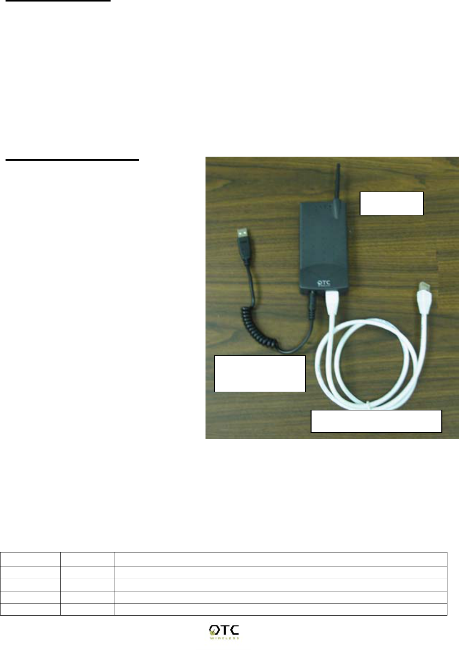
Installing the Hardware
Power
Power is supplied to the radio via
the supplied USB power cord
plugged into a compliant USB-host
port. An optional DC adapter can
be purchased from OTC Wireless,
Inc.
Ethernet Connection
The ACR-201-G is to be connected
to any device’s Ethernet port via
the included white straight-through
UTP cable. Please note that, as
dictated by the 802.11 standards,
only one MAC address can be
supported by a Station radio,
unless IP Bridging feature is
enabled (see Chapter 3 for details),
then multiple devices can use the
ACR-201-G for access via a hub or
a switch, where the blue crossover UTP cable needs to be used.
Status LED’s
Connect the 100-BaseT port (which resembles an over-sized telephone jack) on
the bottom panel of the ACR-201-G to the 100-BaseT port of the computer (or
network device, such as a hub or switch). Power on the ACR-201-G, the LED’s
on the front panel should exhibit the following patterns:
LED Color Light Pattern
ON Red Steady ON
RX Green Steady ON
TX Red Blinking ON, when transmitting 802.11 signal
LINK Yellow Blinking ON, when communicating over the Ethernet port
Cat5 Straight Through
5V USB Power
Adaptor
ACR-201

ACR-201-G Technical Manual 4
Steady ON, when Ethernet connection is not present.
ACR-201-G Technical Manual 5
If the yellow LED stays on continuously, then the Ethernet connection to the
Ethernet port is not made. Check your UTP cable and make sure that a straight-
through cable is used for connecting it to a host and that a crossover cable is
used for connecting it to a hub or switch. If one cannot communicate, and the
yellow LED is off, you may want to re-position the ACR-201-G to a different
location for better RF reception. You may also want to check if the unit is
configured with the proper RF channel and security settings by using the Web-
based Utility software. Refer to Chapter 3 for instructions on how to change the
RF channel and security settings.
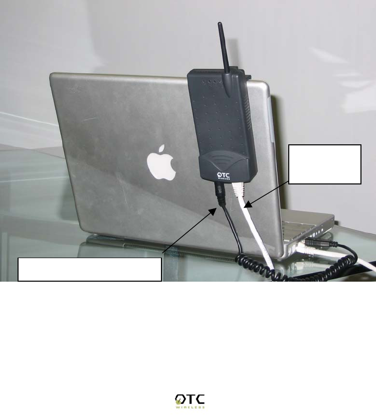
Once the hardware is checked out to work properly with the computer or network
device, the radio can be secured at the top of the laptop LCD display by the
provided radio clip as shown in the following figure.
Stick-on antenna-clip with "corner" shape for edge overhang should prevent user
from mounting it away from the display top corner; such shaped mounting
bracket better than just a flat clip for mounting anywhere.
Typical Installation:
Power drawn from the USB
Ethernet
Connection

ACR-201-G Technical Manual 6
System Requirements for Web-based Utility program
A Web-based Configuration Utility is a built-in program of the Wireless Adapter
for changing the configuration settings of the Adapter. For using the ACR-201-G
Web-based Configuration Utility, your computer must meet the following
requirements:
(1) A Web browser must be installed on the computer. The supported Web
browsers include Internet Explorer 5.0 and above, Netscape 6.0 and above, and
Mozilla 1.0 and above. JavaScript for the browser must be enabled.
(2) Ethernet capable computer with RJ-45 port (either built-in or add-on NIC).
(3) A TFTP (Trivial File Transfer Protocol) client must be installed on the
computer. This requirement is only for the purpose of upgrading the software or
firmware.
No installation of any program is needed. See Chapter 3 for detailed information
of configuring the Wireless Adapter. In order to configure it, you need to know the
factory default settings.
The factory default settings are:
IP address: 169.254.98.200
Subnet mask: 255.255.0.0
(Optional) Gateway: 169.254.1.1
User name: admin
Password: public

ACR-201-G Technical Manual 7
Chapter 3 Web-Based Utility Software
Use the Web-Based Utility Program
Once the ACR-201-G is properly powered up and connected to a computer
running a Web browser on the same IP subnet, the Web-based Utility is ready for
use. To access the web utility, open a Web browser and enter http:// followed by
the current IP address of the ACR-201-G in the location field, for instance http://
169.254.98.200
For configuring your computer to match the IP subnet of your PC to that of the
ACR-201-G radio, different steps must be taken on different operating systems.
Typically, a static IP address must be manually assigned to a computer and the
user must have administrative privilege to perform such operation. Here are
sample configuration steps involved on Windows and Macintosh.
On Windows, select “Start->Settings->Control Panel” and double click “Network
and Dial-up Connections” icon. In the popped up window, right-click “Local Area
Connection” icon and select “Properties” command. In the “Local Area
Connection Properties” dialog, choose “Internet Protocol (TCP/IP)” component in
the “Components checked are used by this connection” section and then click
“Properties” button. In the subsequently popped up “Internet Protocol (TCP/IP)
Properties” dialog, turn on “Use the following IP address” radio button, and enter
the IP address, subnet mask as well other information in the related fields for
your computer.
On Macintosh, select “Apple->System Preferences…” and double click the
“Network“ icon. In the popped up “Network” dialog, choose “Built-in Ethernet”
option for “Shows” dropdown menu and select the “TCP/IP” tab. Choose
“Manually” for the “Configure” dropdown menu, and then enter your IP address,
subnet mask as well as other information in the related fields for your computer.
Overview of the Web Pages
With most browsers, there are six web pages accessible through six tab links.
These web pages are hosted by a built-in web server in the ACR-201-G radio.
Details of each Web page will be discussed in the following sections. The web
pages may look different; however, functions are the same depending on the
combination of operating systems and the web browser being used.
To access any hosted page, you are prompted for a user name and a password.
When accessing a hosted page for the first time, use the factory default settings
listed on the previous page.
The “Save” and “Cancel” buttons are common on “Wireless”, “Advanced”,
“Security”, and “Admin” pages. Clicking the “Save” will apply the settings
according to the displayed value in that particular web page. You will be
prompted to restart the ACR-201-G unit. Please note that you may have to
manually click “Refresh” or “Reload” button of the web browser in order to see
the updated web page due to the caching mechanism of the web browser.
Alternatively, the user can change the setting of the internet browser such that
ACR-201-G Technical Manual 8
the browser would retrieve new web pages instead of displaying the cached web
pages.
Basic Information
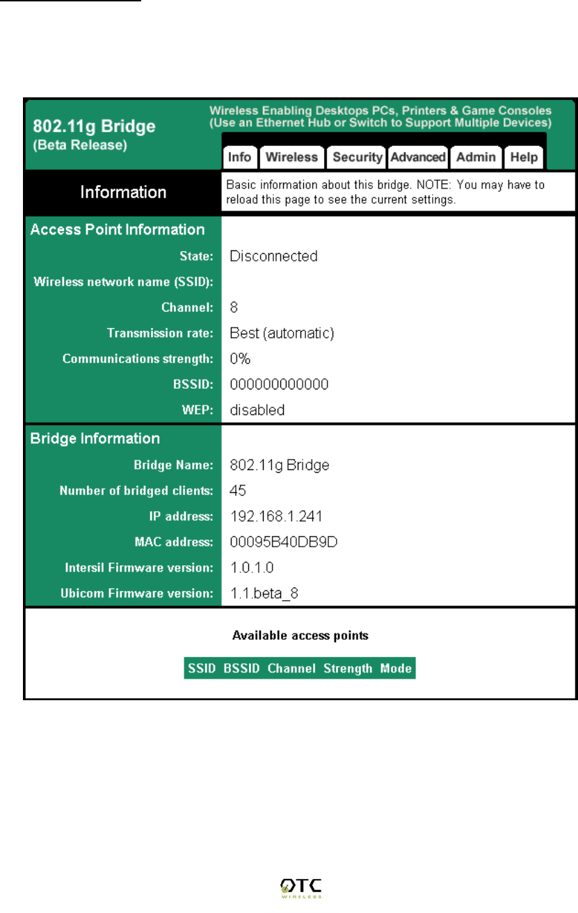
The “Info” page (Figure 1) is the default home page for the built-in web server.
You can click on the “Info” tab to access this page. There are three subsections
in this web page: Access Point Information, Bridge Information, and Available
Access Points.
Figure 1 “Info” Web Page

ACR-201-G Technical Manual 9
1. Access Point Information:
This section displays the information of the wireless connectivity status of ACR-
201-G. Each field is described below.
State
The connection status of the wireless port
Wireless Network Name (SSID)
Shows the SSID of the AP. To change, see “Wireless Configuration” Tab
“Wireless Network Name (SSID)”.
Channel
Shows the channel the AP is operating on. To change channel, see
“Wireless Configuration” Tab “Channel”.
Transmission Rate
The transmission rate established with the access point if in infrastructure
mode or with a station if in ad-hoc mode.
Communication Strength
The indicator of RF communication signal strength.
BSSID
Network Identifier for basic service set
WEP
Shows if WEP (the wireless encryption standard) is enabled or not. To
enable/disable/change WEP settings, see “security” tab WEP.
2. Bridge Information:
This section displays basic information of the ACR-201-G unit
Bridge Name
Name of the ACR-201-G device
Number of Bridged Clients
Number of clients connected to the ACR-201-G bridge.
MAC Address
This is the MAC Address of the Access Point. It is a unique physical
address assigned to the unit by the manufacturer. MAC Address cannot
be changed.
IP Address
IP Address of the Access Point. To manually change the IP Address or let
the Access Point obtain an IP Address from a DHCP Server automatically,
see “IP Addr” tab.

ACR-201-G Technical Manual 10
Intersil Firmware Version
Shows the version info of the Intersil firmware.
Ubicom Firmware Version
Shows the version info of the Ubicom firmware.
3. Available Access Points
This field displays the available access points detected by the ACR-201-G
Bridge.
Wireless
Under this selection, you can configure the basic 802.11g access point settings.
Any new settings will not take effect until the access point is rebooted.
Wireless Mode
Select 'Infrastructure' to connect to a wireless access point, select 'Ad-hoc' to
connect to another bridge or wireless station.
Wireless Network ID (SSID)
Acronym for Service Set Identity. This is the name used to identify which wireless
network (Access Points) the ACR-201-G is going to connect with.
Channel
The channel option is only available when the ACR-201-G is in ad-hoc mode. In
infrastructure mode, the ACR-201-G would use the channel of the connected
access point. If you experience interference (e.g. lost connections or slow data
transfers) you may need to try different channels to see which is the best.
Channels 1-14 are in the 2.4 GHz band.
Transmission rate (Mbits/s)
This is the speed at which the access point will transmit data. Normally you
should select 'best' here. If your wireless network is unusually noisy or quiet, you
may use a fixed low or high rate. The RF environment sometimes can be hostile
to the highest data rate available. That gives rise to the need for trading off
between data rate and link robustness.
PHY Profiles
These profiles control a number of settings for overall wireless network usage.
Their meanings are self-explanatory. Users have 7 options, they are: “802.11 g
only”, “802.11 g only, Maximum Performance”, “802.11 b/g Mixed Mode”, “802.11
b/g Mixed Mode Long”, “802.11 b WiFi”, “802.11 b only”, and “Test Mode”.
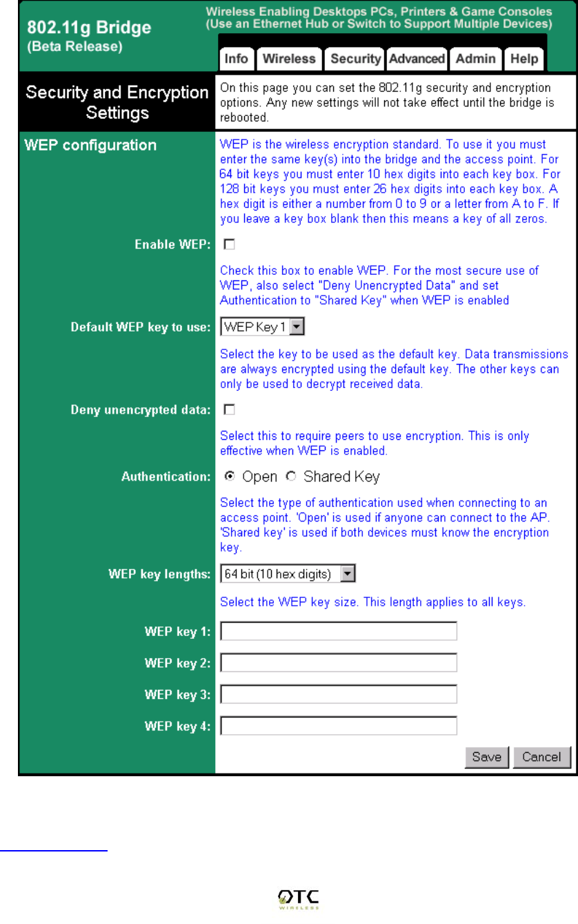
Security
On this page (Figure 3) you can set the 802.11g security and encryption options.
WEP is the wireless encryption standard. To use it, you must enter the same
key(s) into the access point and the wireless stations. For 64 bit keys you must
enter 10 hex digits into each key box. For 128 bit keys you must enter 26 hex
ACR-201-G Technical Manual 11
digits into each key box. A hex digit is either a number from 0 to 9 or a letter from
A to F. Leaving a key box blank implies a key of all zeros.
Figure 3. Security and Encryption Settings
Enabled WEP:

ACR-201-G Technical Manual 12
This check box allows users to enable or disable WEP feature. While WEP is
disabled, all the other fields on this “Encryption” page are disabled too. A set of
four keys needs to be created in the default-key scheme.
Default WEP Key to Use
Select the key to be used as the default key. Data transmissions are always
encrypted using the default key. The other keys can only be used to decrypt
received data.
Deny unencrypted data:
Check this field when the WEP is enabled to deny unencrypted data. This feature
enables the adapter to drop all unencrypted packets received.
Authentication
Three options are available: ‘Open’, ‘Shared Key’, and ‘Both’. 'Open' allows
anyone to authenticate to this access point. 'Shared key' allows only stations that
know the key(s) to authenticate. 'Both' allows a station to use either mode.
WEP key length:
The 64-bit encryption is currently the 802.11 standard. The 128-bit encryption is
supported by equipment from a limited number of vendors. Note that the “user-
controlled” portion of the 64-bit encryption is just 40 bits (10 Hex digits) and that
for the 128-bit encryption is just 104 bits (26 Hex digits)—3-bytes of the
encryption key are internal to the encryption algorithm.
WEP key 1/ 2/ 3/ 4:
The keys allows hex number inputs with varying length depending on the type of
WEP being enabled i.e. 64 or128bit WEP
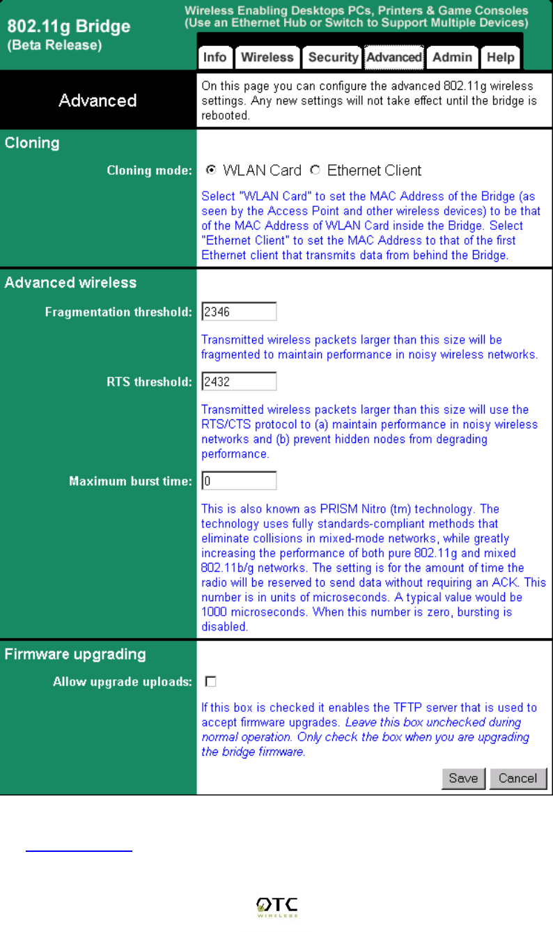
Advance
On this page (Figure 4) you can configure the advanced 802.11g settings such
as Bridging, advance Wireless settings, and Firmware upgrade option.
1. Bridging
To activate the Bridging mode, the user needs to select WLAN card option
allowing multiple clients connecting to an ACR-201-G unit. If Ethernet
client option is selected, the ACR-201-G unit can connect to only a single
client.
2. Advance Wireless
Fragmentation threshold
Transmitted wireless packets larger than this size will be fragmented to
maintain performance in noisy wireless networks. In the presence of
hostile RF environment, such as interference, frames longer than this
threshold numbers in bytes are divided prior to transmission into one or
more fragments equal in length to the fragmentation threshold. The default
value is set at 2346 bytes. The maximum 802.11 data frame size, such
ACR-201-G Technical Manual 13
that no frames are ever fragmented. The valid range of fragmentation
threshold is 256 to 2346, and only even numbers are allowed.
Figure 4. Advanced Wireless
RTS threshold

ACR-201-G Technical Manual 14
Transmitted wireless packets larger than this size will use the RTS/CTS
protocol to (a) maintain performance in noisy wireless networks and (b)
prevent hidden nodes from degrading performance. To minimize the
potential packet collision associated with hidden nodes in a wireless
network, IEEE 802.11 standard has the option to complete a “Request to
Send (RTS)” and “Clear to Send (CTS)” two-frame exchange prior to
sending the real data. This reduces the throughput of the real data. Since
the probability of packet collision increases with the size of the packets
transmitted, an optimum trade-off between data-throughput and data-
integrity may be reached by turning on the two-frame exchange only for
data packets exceeding a certain size. The number entered in this field is
that threshold packet size in Bytes. For example, if “500” is entered, data
packets with sizes less than 500 bytes are transmitted without being
preceded by the RTS-CTS exchange and thereby taking a small risk of
getting corrupted by packet collisions. If “2346” (the maximum 802.11 data
frame size) or a larger number is entered, then every data packet is
transmitted without being preceded by the RTS-CTS exchange and
thereby maximizing the data throughput. The valid range of RTS threshold
is 0 to 3000.
Maximum burst time
This is also known as PRISM Nitro (tm) technology. The technology uses
fully standards-compliant methods that eliminate collisions in mixed-mode
networks, while greatly increases the performance of both pure 802.11g
and mixed 802.11b/g networks. The setting is for the amount of time the
radio will be reserved to send data without requiring an ACK. This number
is in units of microseconds. A typical value would be 1000 microseconds.
When this number is zero, bursting is disabled.
3. Firmware Upgrade
Allow Upgrade Uploads
If this box is checked, it enables the TFTP server that is used to accept
firmware upgrades. Leave this box unchecked during normal operation.
Only check the box when you are upgrading the access point firmware.
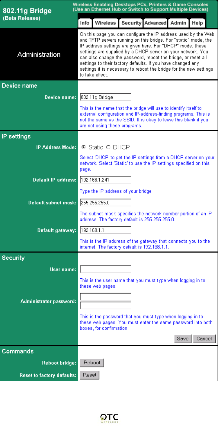
Admin
In this web page, users are able to change settings, which are used for
administration purposes. The web page is divided into four sections: Device
Name, IP settings, Security, and Commands.
1. Device Name:
Device Name
This is the name that the bridge will use to identify itself to external
configuration and IP-address-finding programs. This is not the same as
the SSID. It is okay to leave this blank if you are not using these
programs.

ACR-201-G Technical Manual 15
2. IP Settings:
IP Address Mode
Select 'DHCP' to get the IP settings from a DHCP server on your network.
Select 'Static' to use the IP settings specified on this page.
Default IP address
Type in the IP address of your Access Point. Allows the user to set a static
IP address to the Wireless Adapter. This IP address is only used for
accessing the built-in Web server. In order to access the Web server, the
computer must use an IP address on the same subnet of the Wireless
Adapter. It is not necessary to change this IP address to an address used
by the Wireless Network, but it is okay to do so, if desired. However, if
you do so, please consult with your system or network administrator to
obtain an IP address.
WARNING: Any changes to the following IP settings should be
contemplated carefully, documented well, and made only after
consulting your system or network administrator. Failure to do so
may result in being unable to access the built-in Web server and/or
may affect network operation.
Default subnet mask
The subnet mask specifies the network number portion of an IP address.
The factory default is 255.255.0.0. This allows the user to set the subnet
mask. If you change the IP address to one that is usable in your network,
you may need to change this setting also. Please ask your system or
network administrator for the correct subnet mask.
Default gateway
This is the IP address of the gateway that connects you to the Internet.
Allows the user to set the default gateway. If you change the IP address to
one that is usable in your network, you may need to change this setting
also. Please ask your system or network administrator for the correct
gateway.
ACR-201-G Technical Manual 16
Figure 5. IP Settings
ACR-201-G Technical Manual 17
3. Security
User Name
This is the user name that you must type when logging in to these web
pages.
Administrator Password
This is the password that you must type when logging in to these web
pages. You must enter the same password into both boxes, for
confirmation. The built-in Web server will verify the login name and
password before giving access to the hosted pages. Each time the user
name or password is changed, the Web server will prompt the user for the
new user name and password.
4. Commands
Reboot
Press this button to reboot Access Point. You will need to reboot the unit
after most of the changes you make.
Reset to factory defaults
Press this button to reset to factory default. This button allows the user to
reset all the settings to the factory defaults (not just the fields on this
Admin page!). Please be careful: once reset is completed, the current
settings are all over-written. There is no way to get back to your current
settings unless you remember them or keep an adapter settings copy. It is
always a good idea to keep a copy of the current setting before you
change the current settings.
Help
See the following figure 6:
Figure 6. Help Page

ACR-201-G Technical Manual 18
Chapter 4 Troubleshooting
No Page Displayed When Accessing the Web-based Utility
This is either because the radio is extremely busy on the RF side or because the
Ethernet connection is problematic. Try hitting the “Refresh” or “Reload” button of
the web browser a few times. If the same message persists, it is unlikely that the
problem is caused by a busy radio. Check your Ethernet connection. Make sure
you use at least a legitimate CAT-3 cable, but preferably a CAT-5. Make sure
that it is a straight-through cable between the radio and the computer, or a
crossover cable between the radio and the hub, if a hub is involved. Check to
make sure that the Ethernet card of the computer running the Web-based Utility
program is functional and has a correct IP address and subnet mask setting.
No Radio Link
If the “Communication Strength” indicator on the “Link Info” tab shows 0%, check
the following possible causes:
• Make sure that a target radio, an AP or another Station, is turned on and
operating properly.
• Make sure that the “Signal Strength” indicator on the “Link Info” tab is not
zero. A minimum of 20% is recommended. If the “Signal Strength” is less
than 20%, the distance between the ACR-201-G and the targeted radio
(an AP or another Station) may be too far. Decrease the distance to see if
the radio link can be established.
• Make sure that the SSID is “any” or “ANY” or the same as that for the
Access Point if operating in the infrastructure mode, or the same as that of
the other Stations if operating in the Ad Hoc mode.
• Make sure that the encryption keys are entered correctly if WEP is
enabled.
• Make sure that there is no RF interference present in the radio network.
No Network Connection While the Radio Link is Good
If the “Communication Strength” indicator shows good link quality on the “Link
Info” tab, but the host computer/device cannot be connected to the network
• Make sure that the Yellow LED on the radio is NOT constantly ON. If it is,
Ethernet connection is questionable.
• Make sure the Ethernet Adapter of the host computer/device is properly
installed.

ACR-201-G Technical Manual 19
• Make sure that the UTP cable connecting the radio and the host device
meets at least the CAT-3 standard and has a straight-through connection,
not a crossover.
• Make sure that the ACR-201-G is not connected to a hub with multiple
computers/devices plugged in.
• Make sure that the IP address of the host computer/device is properly set
up for the network.
• Make sure that the host computer/device has initiated some packet traffic
since the radio was turned on. (That is the failure of the network
connection is not just determined by trying to access the host from a
remote point in the network.) Reset or re-power the host with the ACR-
201-G turned on may be necessary in order for the ACR-201-G to “learn”
the MAC address of the host computer.
Poor Link Quality
If the “Communication Strength” stays in the Poor range, it could be due to one of
the following reasons:
• Make sure that radio interference is not present in the radio network.
• Make sure that the radio is not surrounded by many strongly reflecting
(metallic) surfaces. With multiple reflecting surfaces between the radio in
question and the target radio, a severe “multi-path” problem may
introduce high bit error rate despite a strong “Signal Strength”.
• Make sure that there is not a condition of severe packet collision caused
by a “hidden node” problem. A “hidden node” problem is the situation
where the RF signal from two or more Station radios cannot reach each
other (but can reach the AP). In such situation, multiple Stations may
attempt to transmit data packet to the AP at the same time and therefore
cause packet collision. To solve this problem, either re-arrange the
Stations in question such that the RF signals are mutually sensible by all
Stations, or turn-on the RTS/CTS protocol by setting the “RTS threshold”
on the “Config” tab to a reasonably small value (500, for example). There
is no guarantee that the packet collision can be entirely eliminated by
invoking RTS/CTS protocol, but the severity can be reduced enough to
see visible improvement of the link quality.
Radio Interference
You may be able to eliminate RF interference by trying the following:
• Find the “channel” used by the source of the interference and coordinate
your network and the interference source to be on channels that are at
least 20MHz, but preferably 30MHz, apart.

ACR-201-G Technical Manual 20
• Reseat the ACR-201-G radio to a location where the interference is
minimized; in general, increase the distance between the wireless devices
and the device causing the radio interference.
• Avoid using 2.4GHz cordless phone in the vicinity of the radio
• Keep the computer with the ACR-201-G radio away from the microwave
oven and large metal objects.
• Consult the dealer or an experienced radio technician for help.
TFTP Timeouts
If TFTP command timeouts, please check whether you can ping the Wireless
Adapter. Another possible cause for the timeout is the network traffic is too busy.
Settings Appear not to be Modified
Check the version of the software to be upgraded and the software currently
running in the Wireless Adapter. If they are the same, you must click “Reset to
factory defaults” button on index.html page to make software upgrading take
effect. This upgrade effectively overwrites the current software with a different set
of factory defaults.
Technical Support
Please contact OTC Wireless for Technical Support.
E-mail: support@otcwireless.com
Telephone: 1-800-770-6689 (Inside USA), 011-510-490-8288 (Outside USA)

ACR-201-G Technical Manual 21
Appendix A: Limited Warranty
The seller warrants to the end user (“Customer”) that this product will be free
from defects in workmanship and materials, under normal use and service, for
one (1) year from the date of purchase from the seller or its authorized reseller.
The seller’s sole obligation under this express warranty shall be, at the seller’s
option and expense, to repair the defective product or part, or deliver to
Customer an equivalent product or part to replace the defective item.
All products that are replaced will become the property of the seller.
Replacement products may be new or reconditioned.

ACR-201-G Technical Manual 22
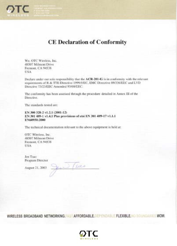
Appendix B: Regulatory Compliance
Federal Communications Commission (FCC) Compliance Information
Statement
FCC Part 15 Declaration of Conformity (DoC)
The following equipment:
Product Name: Wireless Ethernet Adapter
Model Number: ACR-201-G WLAN is herewith confirmed to comply with the
requirements of FCC Part 15 rules. The operation is subject to the following two
conditions:
1. This device may not cause harmful interference, and
2. This device must accept any interference received, including interference that
may cause undesired operation.
FCC ID:
A declaration of conformity with the requirements of the directives is available
from OTC Wireless, Inc. 48507 Milmont Drive, Fremont, California 94538, USA
1-800-770-6698 (USA); 011-510-490-8288 (International)
FCC Rules and Regulations - Part 15
This equipment has been tested and found to comply with the limits for a Class B
digital device, pursuant to Part 15 of the FCC Rules. Operation is subject to the
following two conditions: (1) this device may not cause harmful interference, and
(2) this device must accept any interference received, including interference that
may cause undesired operation.
These limits are designed to provide reasonable protection against harmful
interference in a residential installation. This equipment generates, uses and can
radiate radio frequency energy and, if not installed and used in accordance with
the instructions, may cause harmful interference to radio communications.
However, there is no guarantee that interference will not occur in a particular
installation. If this equipment does cause harmful interference to radio or
television reception, which can be determined by unplugging the equipment and
then plugging it back in, the user is encouraged to try to correct the interference
by one or more of the following measures:
• Reorient or relocate the receiving antenna.
• Increase the separation between the equipment and receiver.
• Connect the equipment into an outlet on a circuit different from that to which the
receiver is connected.
• Consult the dealer or an experienced radio/TV technician for help.
Caution: Changes or modifications not expressly approved by OTC Wireless
could void the user's authority to operate the equipment. This transmitter must
not be co-located or operating in conjunction with any other antenna or
transmitter.

ACR-201-G Technical Manual 23
Exposure to Radio Frequency Radiation
Caution: The radiated output power of this device is far below the FCC radio
frequency exposure limits. In order to avoid the possibility of exceeding the FCC
radio frequency exposure limits, a minimum separation of 20 cm (8 inches) is
recommended between the antenna and any persons.
European Community (EC) Directives Conformity and Restrictions
This product is in conformity with the protection requirements of EC Council
directives 89/336/EEC, 73/23/EEC, and 1999/5/EC on the approximation and
harmonization of the laws of the Member States relating to electromagnetic
compatibility, safety of electrical equipment designed for use within certain
voltage limits and on radio equipment and telecommunications terminal
equipment.
Compliance is indicated by the CE marking
Hereby, OTC Wireless, Inc. declares that this ACR-201-G is in compliance with
the essential requirements and other relevant provisions of Directive 1999/5/EC.
OTC Wireless, Inc. vakuuttaa täten että ACR-201-G tyyppinen laite on direktiivin
1999/5/EY oleellisten vaatimusten ja sitä koskevien direktiivin muiden ehtojen
mukainen.
Hierbij verklaart OTC Wireless, Inc. dat het toestel ACR-201-G in
overeenstemming is met de essentiële eisen en de andere relevante bepalingen
van richtlijn 1999/5/EG
Bij deze verklaart OTC Wireless, Inc. dat deze ACR-201-G voldoet aan de
essentiële eisen en aan de overige relevante bepalingen van Richtlijn 1999/5/EC.
Par la présente OTC Wireless, Inc. déclare que l'appareil ACR-201-G est
conforme aux exigences essentielles et aux autres dispositions pertinentes de la
directive 1999/5/CE
Par la présente, OTC Wireless, Inc. déclare que ce ACR-201-G est conforme
aux exigences essentielles et aux autres dispositions de la directive 1999/5/CE
qui lui sont applicables
Härmed intygar OTC Wireless, Inc. att denna ACR-201-G står I
överensstämmelse med de väsentliga egenskapskrav och övriga relevanta
bestämmelser som framgår av direktiv 1999/5/EG.
Undertegnede OTC Wireless, Inc. erklærer herved, at følgende udstyr ACR-201-
G overholder de væsentlige krav og øvrige relevante krav i direktiv 1999/5/EF
ACR-201-G Technical Manual 24
Hiermit erklärt OTC Wireless, Inc., dass sich dieser ACR-201-G in
Übereinstimmung mit den grundlegenden Anforderungen und den anderen
relevanten Vorschriften der Richtlinie 1999/5/EG befindet". (BMWi)
Hiermit erklärt OTC Wireless, Inc. die Übereinstimmung des Gerätes ACR-201-G
mit den grundlegenden Anforderungen und den anderen relevanten
Festlegungen der Richtlinie 1999/5/EG. (Wien)
ΜΕ ΤΗΝ ΠΑΡΟΥΣΑ OTC Wireless, Inc. ∆ΗΛΩΝΕΙ ΟΤΙ ACR-201-G
ΣΥΜΜΟΡΦΩΝΕΤΑΙ ΠΡΟΣ ΤΙΣ ΟΥΣΙΩ∆ΕΙΣ ΑΠΑΙΤΗΣΕΙΣ ΚΑΙ ΤΙΣ ΛΟΙΠΕΣ
ΣΧΕΤΙΚΕΣ ∆ΙΑΤΑΞΕΙΣ ΤΗΣ Ο∆ΗΓΙΑΣ 1999/5/ΕΚ
Con la presente OTC Wireless, Inc. dichiara che questo ACR-201-G è conforme
ai requisiti essenziali ed alle altre disposizioni pertinenti stabilite dalla direttiva
1999/5/CE.
Por medio de la presente OTC Wireless, Inc. declara que el ACR-201-G cumple
con los requisitos esenciales y cualesquiera otras disposiciones aplicables o
exigibles de la Directiva 1999/5/CE
OTC Wireless, Inc. declara que este ACR-201-G está conforme com os
requisitos essenciais e outras provisões da Directiva 1999/5/CE.

ACR-201-G Technical Manual 25
This product satisfies the radio spectrum requirements of EN 300 328-1, the
EMC requirements of EN 301 489-17 and the safety requirements of EN 60950.
Notice:
In some countries of operation, using this product may be subject to specific
restrictions as listed below. This product is intended only for indoor use.
Outdoor usage may require licensing.
France
Restricted frequency band: only channels 10 through 13 (2446.5 MHz through
2483.5 MHz) may be used in France.
Not allowed for outdoor use in public areas.
Bande de fréquences restreinte : seuls les canaux 10 à 13 (2446,5 MHz à 2483.5
MHz) peuvent être utilisés en France.
Utilisation extérieure interdite dans les zones publiq