Octo Telematics S P A COMPACT01 GSM/GPRS/GPS/Galileo/GLONASS Tracker User Manual Product Specifications
Octo Telematics S.P.A GSM/GPRS/GPS/Galileo/GLONASS Tracker Product Specifications
UserManual.wiki
>
Octo Telematics S P A
>
COMPACT01 User Manual
User Manual
Navigation menu
Upload a User Manual
Namespaces
Wiki Guide
HTML
PDF
Info
Views
User Manual
Discussion / Help
Navigation

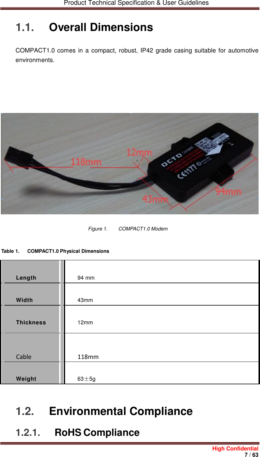
![Product Technical Specification & User Guidelines High Confidential 6 / 63 1 Overview COMPACT1.0 is a wireless modem that allows connectivity on E-GSM/DCS/GSM850/PCS- GPRS networks. The Open AT Application Framework is the world’s most comprehensive cellular development environment that allows embedded standard ANSI C applications to be natively executed directly on the embedded module. For more information about Open AT Application Framework, refer to the documents listed in section 8.1 Remo Wireless Documentation. With the Open AT Application Framework, customers can embed their own applications in this device and turn it into a solution for their specific market need. The operating system of COMPACT1.0 has the ability to fully control the following functions: AT command processing (refer to document [2] AT Commands Interface Guide for Open AT Application Framework Firmware 7.47 for more information) Full GSM or GSM/GPRS Operating System stack GPS Plug-In processing Note: This document does not cover the programmable capabilities available through Open AT Application Framework.](https://usermanual.wiki/Octo-Telematics-S-P-A/COMPACT01/User-Guide-3198648-Page-6.png)

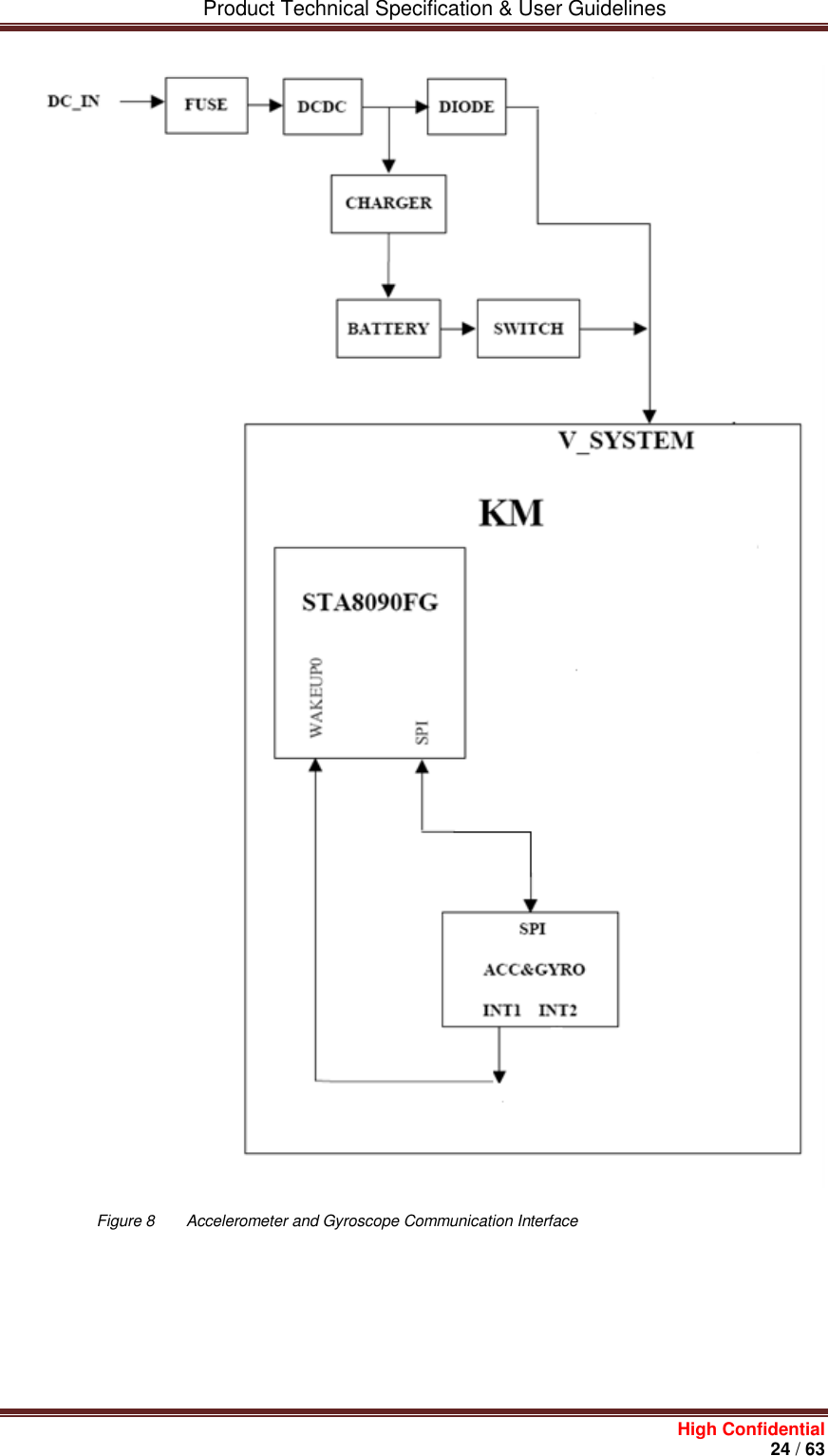
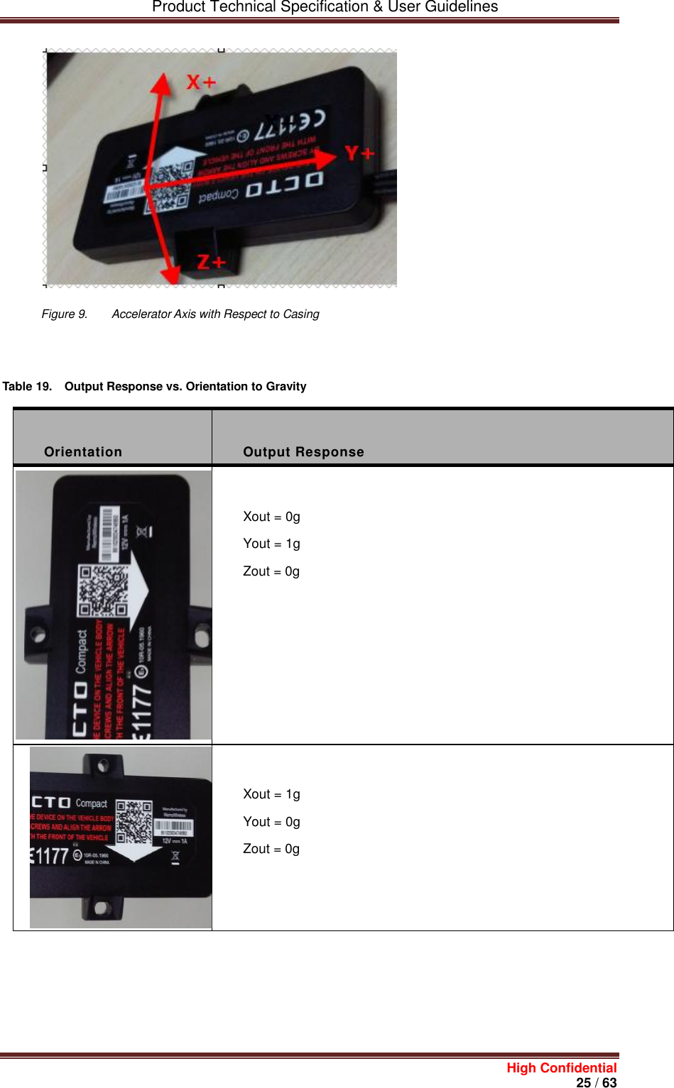
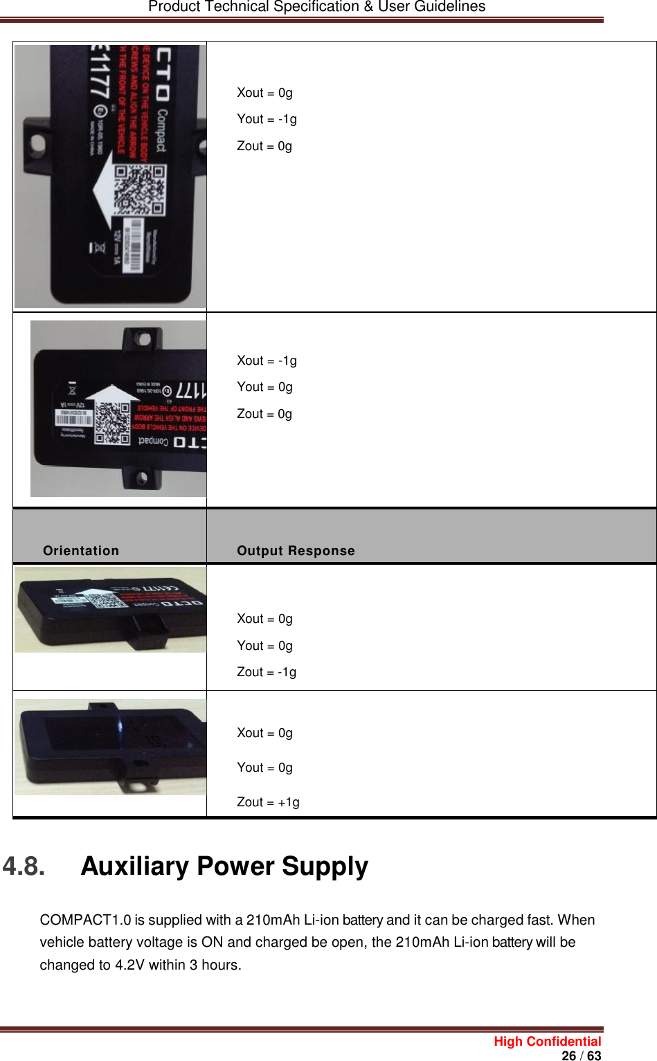
![Product Technical Specification & User Guidelines High Confidential 23 / 63 Watches Fitness, wellness and sports Consumer medical Security/proximity Remote control Home and industrial automation Assisted living Mobile phone peripherals PC peripherals 4.7. Accelerometer&Gyroscope 4.6.1. Accelerometer & Gyroscope COMPACT1.0 has a built-in accelerometer and gyroscope capable of detecting X, Y, Z axis movements and inclination. The accelerometer and gyroscope device used on COMPACT1.0 is LSM6DS3TR. This device communicates with Teseo III through a 4–wire SPI bus. Please refer to document [7] LSM6DS3TR - Accelerometer Specifications for programming configurations of this device.](https://usermanual.wiki/Octo-Telematics-S-P-A/COMPACT01/User-Guide-3198648-Page-23.png)
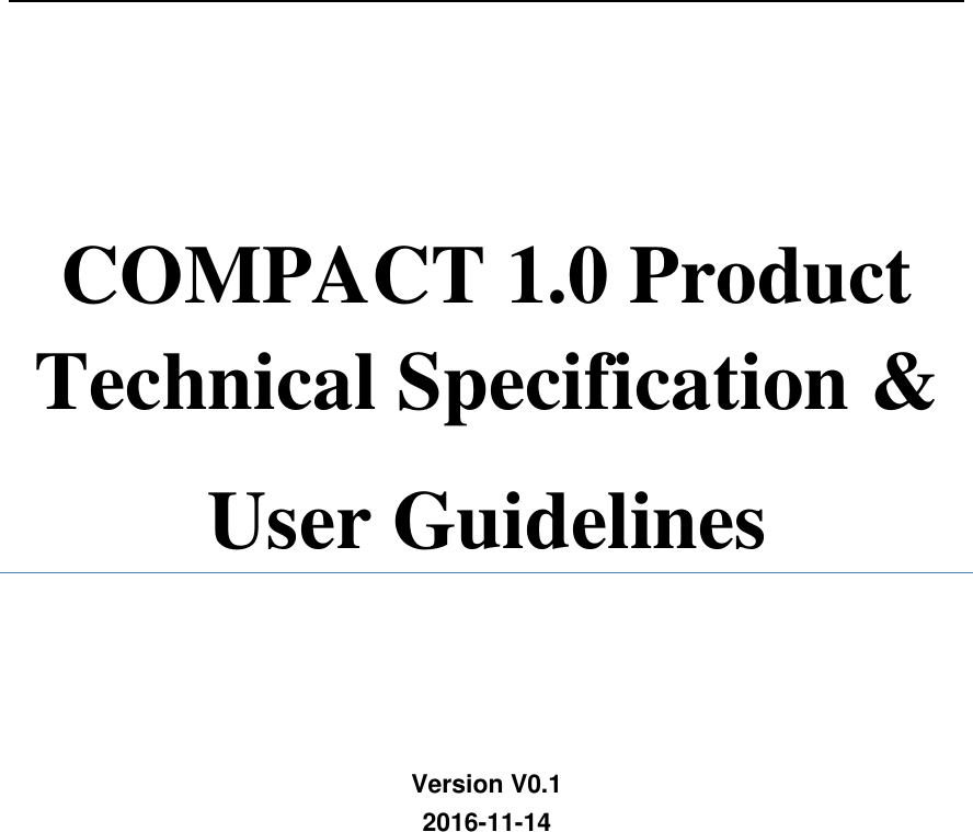
![Product Technical Specification & User Guidelines High Confidential 35 / 63 AT Command Description AT+CGMI To check if the serial link is OK. COMPACT1.0 will respond with "Remo Wireless" when it is OK. AT Command Description AT+CPIN=xxxx To enter a PIN code, xxxx (if activated). AT+CSQ To verify the received signal strength. AT+CREG? To verify the registration of COMPACT1.0 on the network. ATD<phone number> To initiate a GSM call. ATH To hang up (end of GSM call). For further information about these AT commands and their associated parameters, refer to document [2] AT Commands Interface Guide for Open AT Application Framework Firmware 7.47. 5.3. Verifying the Received Signal Strength COMPACT1.0 only establishes a call if the received signal strength is strong enough. Using communication software such as HyperTerminal, enter AT+CSQ to check the received signal strength. The response returned will follow the format +CSQ: <rssi>,<ber>. where: <rssi> = received signal strength indication, and <ber> = channel bit error rate. Refer to the table below for the description of the <rssi> values returned. Table 27. <RSSI> Value Description <rssi> Value Description 0 – 10 Received signal strength is insufficient. 11 – 31 Received signal strength is sufficient.](https://usermanual.wiki/Octo-Telematics-S-P-A/COMPACT01/User-Guide-3198648-Page-35.png)
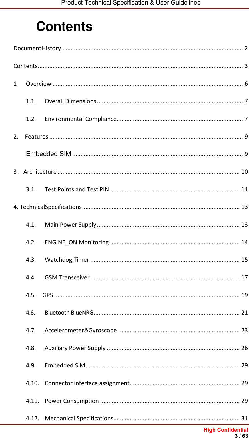
![Product Technical Specification & User Guidelines High Confidential 36 / 63 32 – 98 Not defined. 99 No measure available. Refer to document [2] AT Commands Interface Guide for Open AT Application Framework Firmware7.47 for more information regarding the AT+CSQ AT Command. 5.4. Verifying the Network Registration To check the network registration, make sure that the Embedded SIM has been properly registered. Using a communication software such as HyperTerminal, enter AT+CREG? to verify the network registration of COMPACT1.0. Refer to the table below for the list of main responses returned. Table 28. AT+CREG Main Responses AT+CREG Response Description +CREG: 0,0 Not registered. +CREG: 0,1 Registered on the home network. +CREG: 0,5 Registered on a roaming network. If COMPACT1.0 is not registered on the network, verify the signal strength to determine the received signal strength (refer to section 5.3 Verifying the Received Signal Strength). Refer to document [2] AT Commands Interface Guide for Open AT Application Framework Firmware7.47 for more information regarding the AT+CREG AT Command and other AT commands relating to network registration in GPRS mode. 5.5. Checking the Band Selection Using a communication software such as HyperTerminal, enter AT+WMBS? to check the band selection of COMPACT1.0. Refer to the table below for the list of main responses returned.](https://usermanual.wiki/Octo-Telematics-S-P-A/COMPACT01/User-Guide-3198648-Page-36.png)
![Product Technical Specification & User Guidelines High Confidential 37 / 63 Table 29. AT+WMBS Responses AT+WMBS Response Description +WMBS: 0,x Mono band mode 850MHz is selected +WMBS: 1,x Mono band mode extended 900MHz is selected +WMBS: 2,x Mono band mode 1800MHz is selected +WMBS: 3,x Mono band mode 1900MHz is selected +WMBS: 4,x Dual band mode 850/1900MHz are selected +WMBS: 5,x Dual band mode extended 900MHz/1800MHz are selected +WMBS: 6,x Dual band mode extended 900MHz/1900MHz are selected +WMBS: 7,x Quad band mode 850/ extended 900MHz/1800MHz/1900MHz are selected Where: When x = 0, the band has not been modified since the last boot of COMPACT1.0; When x = 1, the band has been modified since the last boot of COMPACT1.0, and will have to be reset in order to take the previous modification(s) into account. Refer to document [2] AT Commands Interface Guide for Open AT Application Framework Firmware7.47 for more information regarding the AT+WMBS AT Command. 5.6. Switching Bands Using communication software such as HyperTerminal, enter AT+WMBS to change the band settings of COMPACT1.0 and switch between EU (EGSM900/DCS1800) and US (GSM850/ PCS1900) bands and vice versa. Refer to the following table for the list of AT+WMBS parameters that can be used and their corresponding description. Table 30. AT+WMBS Band Selection AT+WMBS Command Description](https://usermanual.wiki/Octo-Telematics-S-P-A/COMPACT01/User-Guide-3198648-Page-37.png)
![Product Technical Specification & User Guidelines High Confidential 38 / 63 AT+WMBS=0,x Switch to mono band mode 850MHz AT+WMBS=1,x Switch to mono band mode extended 900MHz AT+WMBS=2,x Switch to mono band mode 1800MHz AT+WMBS=3,x Switch to mono band mode 1900MHz AT+WMBS=4,x Switch to dual band mode 850/1900MHz AT+WMBS Command Description AT+WMBS=5,x Switch to dual band mode extended 900MHz/1800MHz AT+WMBS=6,x Switch to dual band mode extended 900MHz/1900MHz AT+WMBS=7,x Switch to quad band mode 850/ extended 900MHz/1800MHz/1900MHz Where: When x = 0, COMPACT1.0 will have to be reset to start on the specified band(s); When x = 1, the band switch is effective immediately. However, this mode is forbidden while in Connected mode and during COMPACT1.0 initialization. Refer to document [2] AT Commands Interface Guide for Open AT Application Framework Firmware7.47 for more information regarding the AT+WMBS AT Command. 5.7. Checking the PIN Code Status Using a communication software such as HyperTerminal, enter AT+CPIN? to check the PIN code status. Refer to the table below for the list of main responses returned. Table 31. AT+CPIN Main Responses AT+CPIN Response Description +CPIN: READY The PIN code has been entered. +CPIN: SIM PIN The PIN code has not been entered. Refer to document [2] AT Commands Interface Guide for Open AT Application Framework Firmware7.47 for more information regarding the AT+CPIN AT Command.](https://usermanual.wiki/Octo-Telematics-S-P-A/COMPACT01/User-Guide-3198648-Page-38.png)
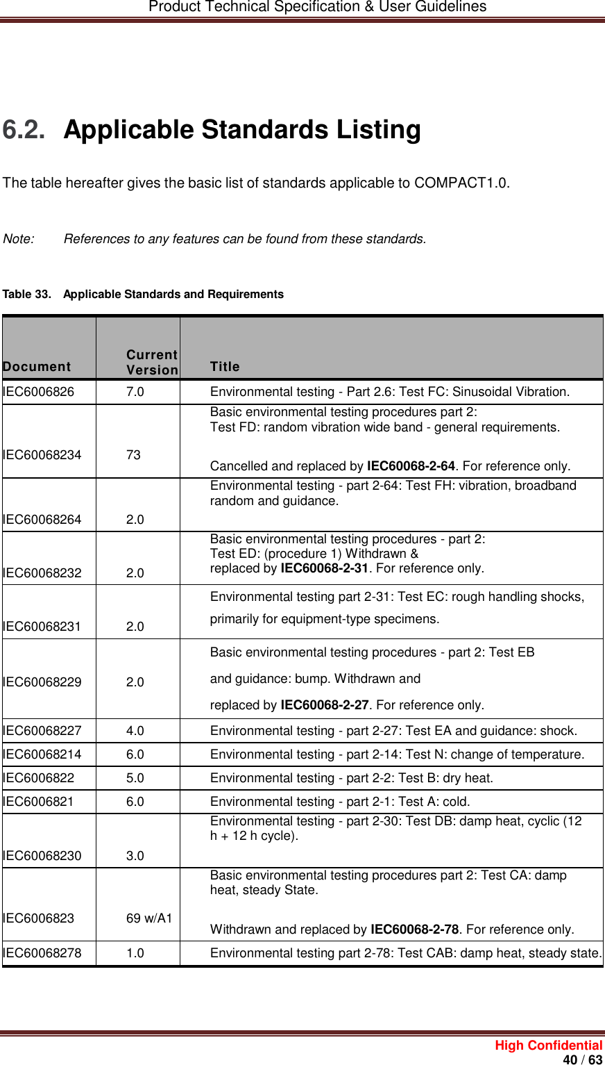
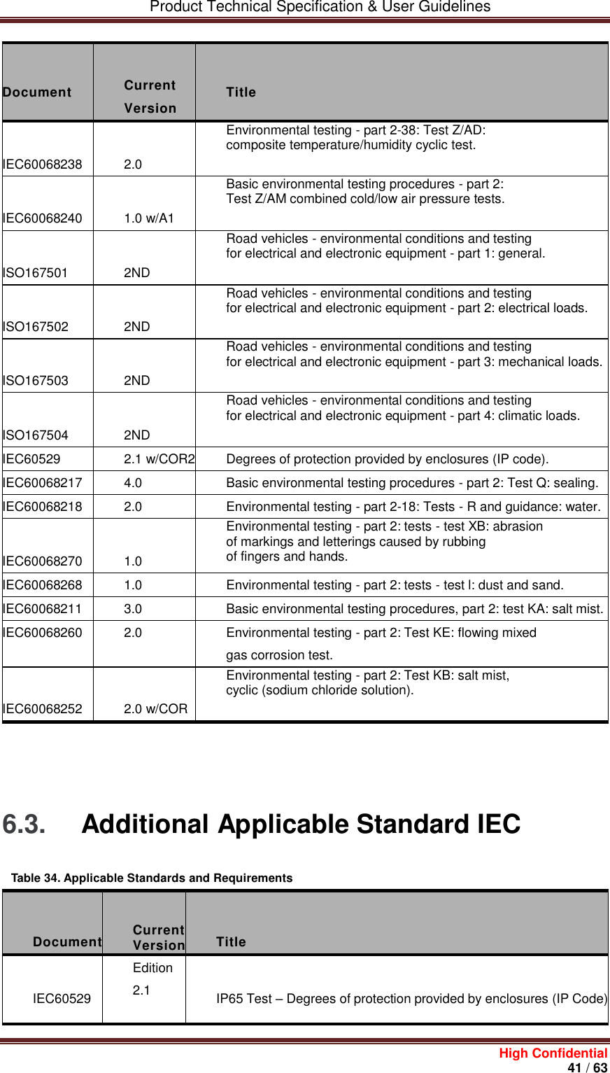
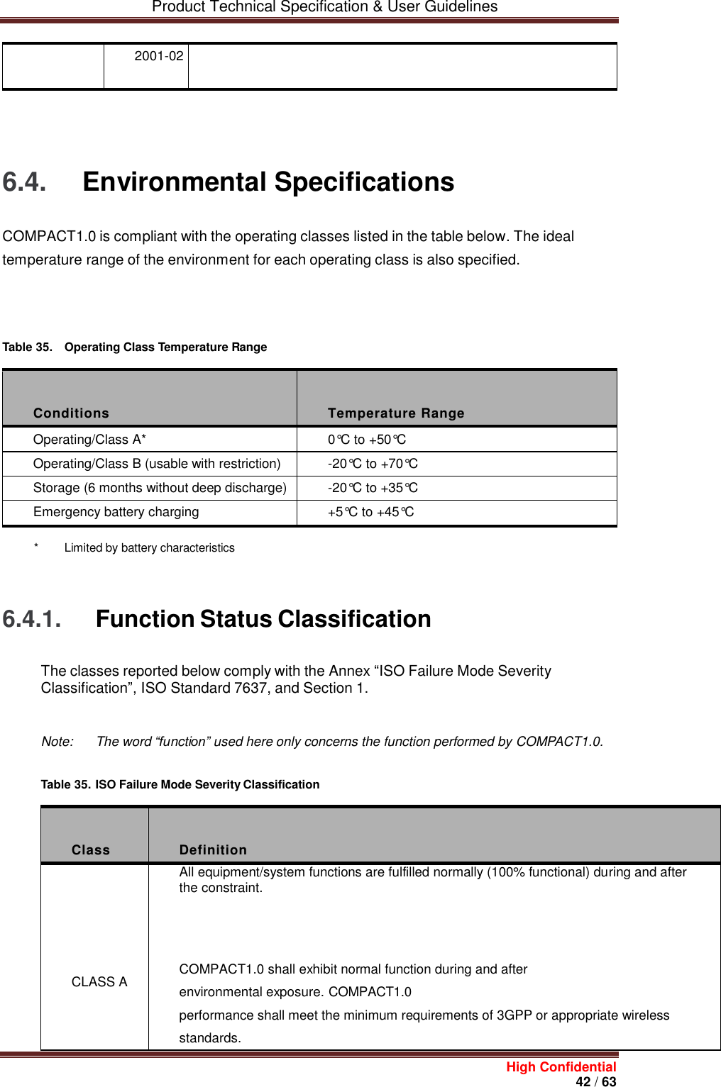
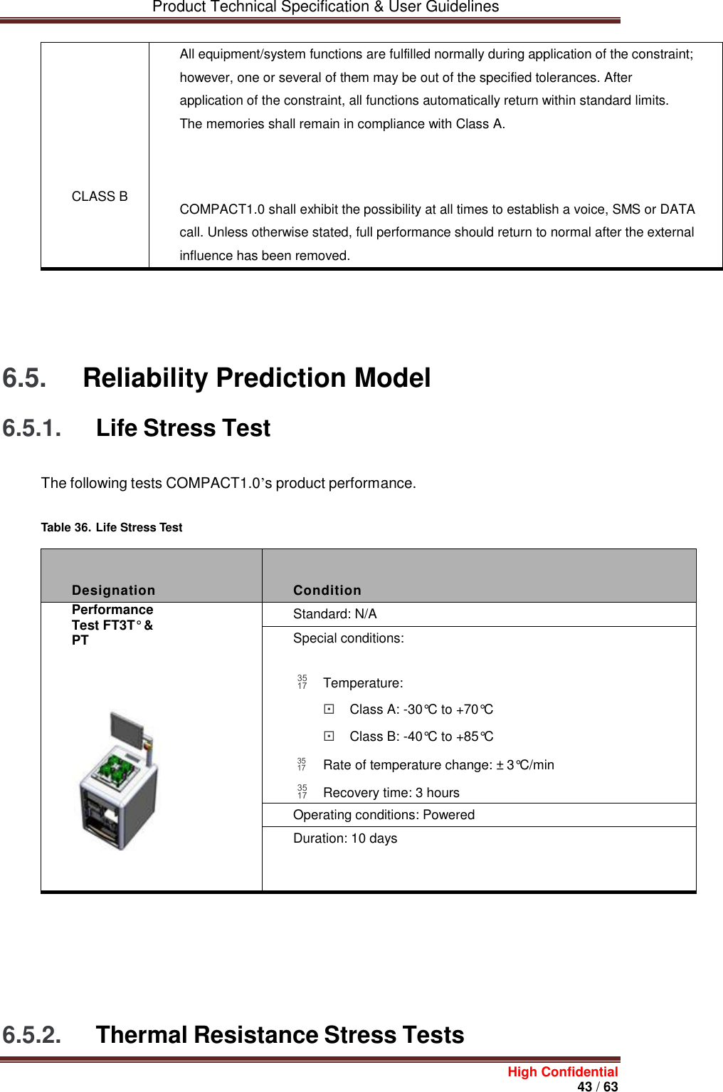
![Product Technical Specification & User Guidelines High Confidential 39 / 63 5.8. Resetting COMPACT1.0 Resetting COMPACT1.0 could be triggered by the AT command AT+CFUN=1, or by unplugging and then re-plugging the power supply (Vin). 5.9. Operating System Upgrade Procedure COMPACT1.0 operating system is stored in flash memory and can be easily upgraded. The operating system file can be downloaded into the modem using the X-modem protocol. The AT+WDWL command allows the download process to be launched. The operating system file can also be downloaded into the modem using the DOTA (download over the air) feature. This feature is available with the Open AT Application Framework interface. Refer to document [2] AT Commands Interface Guide for Open AT Application Framework Firmware7.47 for more information regarding this procedure. 6. Reliability Compliance and Recommended Standards 6.1. Reliability Compliance COMPACT1.0 is compliant with the following requirements: Table 32. Standards Conformity Abbreviation Definition IEC International Electro technical Commission ISO International Organization for Standardization](https://usermanual.wiki/Octo-Telematics-S-P-A/COMPACT01/User-Guide-3198648-Page-39.png)
![Product Technical Specification & User Guidelines High Confidential 53 / 63 [1] ADL User Guide for Open AT Application Framework OS 6.37 [2] AT Commands Interface Guide for Open AT Application Framework Firmware 7.47 [3] Product Technical Specification and Customer Design Guidelines [4] STA8090 Product Technical Specification and Customer Design Guidelines 8.2. General Reference Documentation [5] “I2C Bus Specification”, Version 2.0, Philips Semiconductor 1998 [6] ISO 7816-3 Standard [7] LSM6DS3TR - Accelerometer Specifications [8] TCA9535RTWR - IO Expander Specifications 9. List of Abbreviations Abbreviation Definition AC Alternative Current ADC Analog to Digital Converter A/D Analog to Digital conversion AF Audio-Frequency AT ATtention (prefix for modem commands) AUX AUXiliary CAN Controller Area Network CB Cell Broadcast CEP Circular Error Probable CLK CLocK](https://usermanual.wiki/Octo-Telematics-S-P-A/COMPACT01/User-Guide-3198648-Page-53.png)