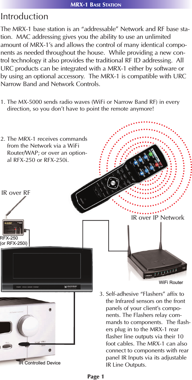
Ohsung Electronics URCMRX1 NETWORK BASE STATION User Manual User s Manual G

Ohsung Electronics Co., Ltd. NETWORK BASE STATION User s Manual G

Users Manual

  Order Number  : GETEC-C1-09-223  FCC Class B Certification Test Report Number  : GETEC-E3-09-128  Page 1 / 1  EUT Type: Network Base Station   FCC ID.: OZ5URCMRX1   APPENDIX G : USER’S MANUAL
MRX-1 Installation ManualNetwork Base Station
MRX-1 Installation Manual ©2009 Universal Remote Control, Inc.The information in this manual is copyright protected. No part of this man-ual may be copied or reproduced in any form without prior written consentfrom Universal Remote Control, Inc. UNIVERSAL REMOTE CONTROL, INC. SHALL NOT BE LIABLE FOR OPER-ATIONAL, TECHNICAL OR EDITORIAL ERRORS/OMISSIONS MADE INTHIS MANUAL.  The information in this manual may be subject to change without priornotice. Complete Control is a registered trademark of Universal Remote Control,Inc.  All other brand or product names are trademarks or registered trademarksof their respective companies or organizations.500 Mamaroneck Avenue, Harrison, NY 10528 Phone: (914) 835-4484 Fax: (914) 835-4532
TABLE OFCONTENTSIntroduction 1Features and Benefits 2Parts Guide 2Network Installation and Control 3IR over Narrow Band via Optional RFX-250 5Optimizing IR Flasher Levels 7Integrating Optional RFTX-1 to control URC Lighting 8Overview of IR Routing 9Network or RF setup in CCP 9Frequently Asked Questions 11Specifications 11USA Limited Warranty Statement 12Information to the User 13Warning 13
Page 1MRX-1 BASE STATIONIntroductionThe MRX-1 base station is an “addressable” Network and RF base sta-tion.  MAC addressing gives you the ability to use an unlimitedamount of MRX-1’s and allows the control of many identical compo-nents as needed throughout the house.  While providing a new con-trol technology it also provides the traditional RF ID addressing.  AllURC products can be integrated with a MRX-1 either by software orby using an optional accessory.  The MRX-1 is compatible with URCNarrow Band and Network Controls. 3. Self-adhesive “Flashers” affix tothe Infrared sensors on the frontpanels of your client’s compo-nents. The Flashers relay com-mands to components.  The flash-ers plug in to the MRX-1 rearflasher line outputs via their 10foot cables. The MRX-1 can alsoconnect to components with rearpanel IR Inputs via its adjustableIR Line Outputs.2. The MRX-1 receives commandsfrom the Network via a WiFiRouter/WAP; or over an option-al RFX-250 or RFX-250i. 1. The MX-5000 sends radio waves (WiFi or Narrow Band RF) in everydirection, so you don’t have to point the remote anymore! IR over IP NetworkIR over RFRFX-250 (or RFX-250i)   WiFi RouterIR Controlled Device
Page 2MRX-1 BASE STATIONFeatures and BenefitsThe Bridge for Network Remotes and KeypadsThe MRX-1 enables IR and RS-232 devices to be controlled by URCNetwork Controls. Via the optional RFX-250 or RFX-250i, tradition-al Narrow Band RF remotes and keypads can also control the sameIR and RS-232 devices.2-Way RS-232 Thermostats, Security Systems, Home Theater AVRSand Multi-Zone MatrixesVia the unique URC 2-Way database installers can drag and drop2-Way pre-programmed modules into any URC Network Controlpowered by the MRX-1’s two RS-232 ports. RS-232 componentscan display Volume Pop Ups, Status displays, Tuner Modules, 2-Way Transport Controls, etc.Whole House URC Lighting via RFTX-1Via the RFTX-1 transmitter, the MRX-1 can relay commands fromany URC Network Control to URC Lighting devices. By installingmultiple MRX-1/RFTX-1 relay stations around a home, installers cancreate seamless coverage of any size house, allowing lighting pathsand whole house scenes.Utilize MRX-1 Sensor Port to Automate TOAD Devices  The MRX-1 offers URC Network Controls automation capability fordevices that do not have discrete codes. It is equipped with a sen-sor port compatible with optional URC video or voltage sensors,thus an installer can program macros that test whether a device ison or off before issuing input commands etc.Control Devices with RelaysURC Network Controls can control lifts, screens etc. via the MRX-1’s NO, NC or Momentary set of contacts.Parts GuideThe MRX-1 Network Base Station includes:1 - MRX-1 Network Base Station1 - 12V-1000mA Power Supply6 - Visible Emitters with 10 foot plugin cables including 1 pink sleevedemitter for the RFTX-1 port1 - Ten feet 3.5mm Stereo to3.5mm Stereo (for daisy chainingmultiple MRX-1 with one RFX-250)1 - Adjustment Tool1 - Mounting Plate for wall mountingthe MRX-1
Page 3Network Installation and Control1. Connect the Ethernet cable (RJ45) to the rear of the MRX-1 andinto the network router.2. Open the CCP editor.3. Select Program then Configure Home.4. Add a MRX-1 base station and the properties window opens. 5. Either type in the MAC address which can be found on a stickerlocated on the bottom of the unit or click on the Discover but-ton. 6. The Discover window opens to reveal a list of connected MRX-1units. Highlight the preferred MRX-1 MAC address and selectApply. The Discover window closes.MRX-1 BASE STATIONThe MRX-1 is a network base station that allows full control of yourcomponents. Once installed to the network, press a button on theremote to send a command via WiFi over the customer’s network.The MRX-1 receives and sends IR, RS232 and Relay commands tothe devices you specify. Note that the MRX-1 sensor can only beutilized by URC Network Controls. Status
Page 47. Now the MRX-1’s MAC address will populate the MAC addressfield.8. Press OK to close the window.  9. Plug flashers into any of the six flasher ports on the MRX-1.  Ifyou utilize IR output #6, you must use the pink sleeved flasher.IR Output #6 is dual purpose, it can be used as an IR flasher or itcan control the RFTX-1 for URC Lighting. MRX-1 BASE STATIONStatus
Page 5IR Over Narrow Band via Optional RFX-250Note: RF remotes via RFX-250 can only control IR components.RS232, Relay and Sensor control are not available to RF remotes.1. Power on all AV components, lower all dimmers to 50% andpower on anything that may create RF Interference (particularlydevices with high speed microprocessors or hard drives).2. Check that the address wheel on the back of the MRX-1 is set toID#0 (the interference “sniffing” position).Check that the arrow pointer in the center of the wheel is pointed to 0, thedefault “interference sniffing” position.  If it is not, use the included smallflat blade screwdriver to set the RF ID# to 0.3. Connect the MRX-1 to its DC wall adapter and plug the walladapter into a live AC outlet. Place the MRX-1 in a convenientcentral location in the equipment rack. Unlike an MRF-250, theMRX-1 can be placed next to components with hard drives orhigh speed microprocessors.  There is no RF circuitry inside theMRX-1 itself.4. Connect the RFX-250 to the MRX-1’s RF INPUT jack as shown. MRX-1 BASE STATIONWhen connecting a single RFX-250 to the MRX-1 utilize the cable with 3.5mm plugs on both ends. When you need a longer wire or are connectingup to three RFX-250s, use a cable with tinned ends or splice it. Cable canbe extended as much as 200’, then connected to the spliced end of a3.5mm cable.
Page 6MRX-1 BASE STATION5. Observe the RF LED of the RFX-250. Cup your hand over theRFX-250’s RF LED. If it is glowing or flickering you must relocatethe RFX-250 to a location where the LED does not flicker.6. Observe the STATUS LED of the MRX-1. It is a little more sensi-tive than the RFX-250. If you see any flickering of this LED, movethe RFX-250 to a new location.  If your installation location sim-ply doesn’t offer you any choice and you are detecting interfer-ence everywhere you place the RFX-250, you have three lastresort options:a. Remove the RFX-250’s antenna. This will reduce therange enormously, but may still be enough for this client.b. Extend a wire to another room. Try this over the floorfirst, before attempting to conceal the wire.c. Admit defeat and install a “pointing again” IR repeatersystem. If no buttons are pressed on any remote control,no valid RF transmissions are being received. 7. Once you have found a location that is absolutely clean with allcomponents on, test to see if the range is adequate and thatmacro reliability is perfect. Start with the antenna angle set to 45degrees and positioned so that the long side of the antenna is fac-ing the customer’s favorite seating position. When testing, setboth the remote and the MRX-1 to the same VALID RF ID#. Keepin mind that zero (0) is not a valid RFID#. Watch the STATUSLED on MRX-1 - it should light every time you press a button onthe remote. This will tell you that the signal was received andunderstood. You can ignore the RF LED on the RFX-250 (it onlyindicates that a signal was received, not that it was understood).8. If the range is inadequate, you may extend the wire to any areathat is not getting good results and place an additional RFX-250in that area. Up to three RFX-250s can be connected to oneMRX-1.9. Should you need more than six IR Outputs, connect as many asthree different MRX-1s to one RFX-250 in a daisy chain using thesupplied cable. To preserve addressability, set each MRX-1 to adifferent RF ID number. Remember “0” (zero) is not a valid RFID.
Page 7MRX-1 BASE STATIONOptimizing IR Flasher LevelsTest a few commands for each device before fixing the flasher inplace on the front panel of a device.Since TiVo, Replay TV, Satellite Receivers and Cable Boxes are allextremely sensitive to IR overload or saturation, you should testthem thoroughly. Put up the on screen guide and test the navigationarrows. Compare operation via RF to the original remote control.Operation should be identical. If operation is inconsistent or slug-gish, lower the IR line output and/or reposition the flasher. If you still have sluggish operation, check that the remote control isset to a particular LINE OUT, rather than ALL. When IR commandsare sent to all the flashers in a cabinet, you can have difficultyadjusting the IR Output. Reprogram the remote control to send IRcommands only via a specific (1-6) Line Output, then readjust theIR Line Output level.1.  Connect an IR emitter to each IR output and run the emitterwire to the front panel of each component.  DO NOT STICK theemitter in place. ADJUST the level first.2.  Adjust each of the IR Output levels for best operation. If thecomponent operates best at minimum level, but is still operatingsluggishly or intermittently, move the emitter farther away fromthe components IR sensor.
Page 8MRX-1 BASE STATIONIntegrating Optional RFTX-1 to control URCLightingNot only will you have greater control of your home theatre equip-ment with the MRX-1, now you also have control of your URCLighting.  What better way to watch a movie and control your uni-verse! 1. Simply plug the RFTX-1 with the 10’ pink connecting cable(included with the RFTX-1) into the MRX-1 pink fixed port #6.2. Set the URC Lighting Device in the CCP Editor to RF and set theIR output to Port #6. 3. Download to the MX remote and begin controlling your lights.
Page 9MRX-1 BASE STATIONOverview of IR RoutingThere are several considerations to take into account when you areinstalling an MRX-1 to control an array of identical components:1. Each identical component must receive IR commands ONLYfrom a dedicated Flasher affixed to its front panel or a rear paneldirect IR input.  The SIGNAL of the remote should be set toNetwork or RF ONLY for each identical component. IR can stillbe utilized for other devices in your system!2.  When connecting a flasher from the MRX-1 to your componentmake sure to notate the Flasher Output Number being used.   Network or RF Setup in CCP1. Open the RF Setup Window in CCPThe RF Setup window opens after selecting RF Control from theProgram Menu. The RF Setup window is composed of a “spreadsheet” of options for EACH of your devices. 2. Adjust the Signal For Each of the Identical DevicesThe RF Setup window enables you to adjust the Signal output foreach device individually, by clicking on the intersection of a rowand a column and then selecting Network or RF (for optional RFX-250) from the three options shown in the pull down list box.
Page 10MRX-1 BASE STATIONSelect Network or RF (for optional RFX-250) from the threeoptions shown for EACH of the identical TVs. You may leave theother components with no flashers set to IR.3. Select a Receiver to Control Identical DevicesChoose a Base station to send commands over the Network or viaRF to control multiple components.4. Adjust the IR Outputs For Each of the Identical DevicesThe RF Setup window enables you to adjust which Flashers outputby the remote control for each device individually, by clicking onthe intersection of a row and a column and then selecting Ports 1-6from the seven options shown in the pull down list box. Select the correct IR Output (refer to your connection notes) forEACH of the identical TVs. You may leave the other components ofthe system set to ALL. In the figure below, each device is set to aspecific flasher.5. Close the RF window and Download to the Remote.
Page 11MRX-1 BASE STATIONFrequently Asked QuestionsCan I use flasher/emitters that I have already installed in the sys-tem to connect to the MRX-1?Yes, the flashers are compatible if they use 3.5mm plugs with thesame polarity (Tip is data, sleeve is ground). It is important to notatethe RFTX-1 shared port utilizes a sleeved emitter for long term use. I’m getting inconsistent operation regardless of flasher level orposition.Some components are easily overloaded with IR from nearby flashers.Prevent IR from affecting the problem component from other flashers bysetting the device to a specific IR Line Output instead of ALL, then adjustthe Line Output.I am unable to control my URC Lighting Dimmer/Switch with theMRX-1. Now what?Make sure the RF switch on the RFTX-1 is set to the correct fre-quency for the URC Dimmer or Switch.  URC Lighting ModelsMRFA is 418MHz and MRFB is 433MHz.How do I update the firmware?Make sure the MRX-1 is connected to the Network then open CCPand click on the Firmware button locatedHow can I set my MRX-1 to factory default?Look on the bottom of the MRX-1 and remove the cover plate toreveal a reset button.  Simply press the button with a pen or thinobject to reset the unit. SpecificationsNetwork: One 10/100 Ethernet portRelay: One relay configurable to be NO, NC or MomentarySensor: One sensor supports Video or Voltage sensing via URC sen-sors.RS-232: Two RS-232 ports support TX, RX and GND two way com-munication via URC cables.IR: Six adjustable IR ports enable the included URC emitters tocontrol IR devices Note: 6th IR Output requires the includedsleeved emitter (identified by a pink connector), since it can option-ally be used to connect an RFTX-1Weight: 8.4 oz. Size: 248 x 120mm x28mmPower:  12v External Power Supply
Page 12USA Limited Warranty StatementYour Universal Remote Control, when delivered to you in newcondition, is warranted against defects in materials or work-manship as follows: UNIVERSAL REMOTE CONTROL, INC.warrants this product against defects in material or workman-ship for a period of one (1) year and as set forth below.Universal Remote Control will, at its sole option, repair theproduct using new or comparable rebuilt parts, or exchange theproduct for a comparable new or rebuilt product. In the eventof a defect, these are your exclusive remedies.This Limited Warranty covers only the hardware componentspackaged with the Product. It does not cover technical assis-tance for hardware or software usage and it does not cover anysoftware products whether or not contained in the Product; anysuch software is provided "AS IS" unless expressly provided forin any enclosed software Limited Warranty. To obtain warranty service, you must deliver the product,freight prepaid, in its original packaging or packaging affordingadequate protection to Universal Remote Control at the addressprovided in the Owner's Manual. It is your responsibility tobackup any macro programming, artwork, software or othermaterials that may have been programmed into your unit. It islikely that such data, software, or other materials will be lostduring service and Universal Remote Control will not beresponsible for any such damage or loss. A dated purchasereceipt, Bill of Sale, Installation Contract or other verifiableProof of Purchase  is required. For product support and otherimportant information visit Universal Remote Control's website:http://www.UniversalRemoteControl.com or call the UniversalRemote Control Customer Service Center (914) 835-4484. This Limited Warranty only covers product issues caused bydefects in material or workmanship during ordinary consumeruse. It does not cover product issues caused by any other rea-son, including but not limited to product issues due to commer-cial use, acts of God, third-party installation, misuse, limita-tions of technology, or modification of or to any part of theUniversal Remote Control product. This Limited Warranty doesnot cover Universal Remote Control products sold as USED, ASIS, REFURBISHED, so-called "B STOCK"  or consumables (suchas batteries). This Limited Warranty is invalid if the factory-applied serial number has been altered or removed from theproduct. This Limited Warranty is valid only in the United Statesof America. This Limited Warranty specifically excludes prod-ucts sold by unauthorized resellers.MRX-1 BASE STATION
Page 13This equipment has been tested and found to comply withthe limits for a Class B digital device, pursuant to part 15 ofthe FCC Rules. These limits are designed to provide reason-able protection against harmful interference in a residentialinstallation. This equipment generates, uses and can radiateradio frequency energy and, if not installed and used inaccordance with the instructions, may cause harmful interfer-ence to radio communications.However, there is no guarantee that interference will notoccur in a particular installation. If this equipment does causeharmful interference to radio or television reception, whichcan be determined by turning the equipment off and on, theuser is encouraged to try to correct the interference by onemore of the following measures:Reorient or relocate the receiving antenna.Increase the separation between the equipment andreceiver.Connect the equipment into an outlet on a circuit dif-ferent from that to which the receiver is connected.Consult the dealer or an experienced radio/TV techni-cian for help.WarningChanges or modifications not expressly approved by the manu-facturer could void the user's authority to operate the equip-ment.Note : The manufacturer is not responsible for any Radio or TVinterference caused by unauthorized modifications to thisequipment. Such modifications could void the user's authorityto operate the equipment.Information To The UserMRX-1 BASE STATION
Page 14MEMO
Page 15MEMO
Page 16MEMO
500 Mamaroneck Avenue, Harrison, NY 10528 Phone: (914) 835-4484 Fax: (914) 835-4532 www.universalremote.comOCE-0076A Rev.01

Navigation menu