Ohsung Electronics URCMRX1 NETWORK BASE STATION User Manual User s Manual G
Ohsung Electronics Co., Ltd. NETWORK BASE STATION User s Manual G
Users Manual

Order Number : GETEC-C1-09-223 FCC Class B Certification
Test Report Number : GETEC-E3-09-128 Page 1 / 1
EUT Type: Network Base Station
FCC ID.: OZ5URCMRX1
APPENDIX G
: USER’S MANUAL
MRX-1 Installation Manual
Network Base Station

MRX-1 Installation Manual ©2009 Universal Remote Control, Inc.
The information in this manual is copyright protected. No part of this man-
ual may be copied or reproduced in any form without prior written consent
from Universal Remote Control, Inc.
UNIVERSAL REMOTE CONTROL, INC. SHALL NOT BE LIABLE FOR OPER-
ATIONAL, TECHNICAL OR EDITORIAL ERRORS/OMISSIONS MADE IN
THIS MANUAL.
The information in this manual may be subject to change without prior
notice.
Complete Control is a registered trademark of Universal Remote Control,
Inc.
All other brand or product names are trademarks or registered trademarks
of their respective companies or organizations.
500 Mamaroneck Avenue, Harrison, NY 10528
Phone: (914) 835-4484 Fax: (914) 835-4532

TABLE OFCONTENTS
Introduction 1
Features and Benefits 2
Parts Guide 2
Network Installation and Control 3
IR over Narrow Band via Optional RFX-250 5
Optimizing IR Flasher Levels 7
Integrating Optional RFTX-1 to control URC Lighting 8
Overview of IR Routing 9
Network or RF setup in CCP 9
Frequently Asked Questions 11
Specifications 11
USA Limited Warranty Statement 12
Information to the User 13
Warning 13
Page 1
MRX-1 BASE STATION
Introduction
The MRX-1 base station is an “addressable” Network and RF base sta-
tion. MAC addressing gives you the ability to use an unlimited
amount of MRX-1’s and allows the control of many identical compo-
nents as needed throughout the house. While providing a new con-
trol technology it also provides the traditional RF ID addressing. All
URC products can be integrated with a MRX-1 either by software or
by using an optional accessory. The MRX-1 is compatible with URC
Narrow Band and Network Controls.
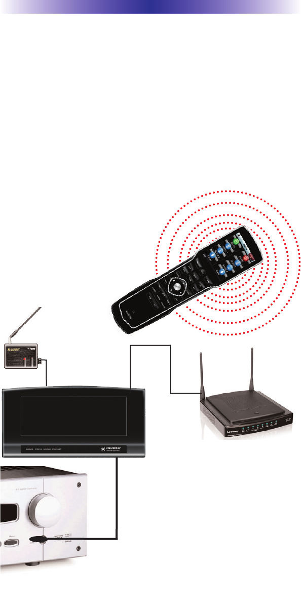
3. Self-adhesive “Flashers” affix to
the Infrared sensors on the front
panels of your client’s compo-
nents. The Flashers relay com-
mands to components. The flash-
ers plug in to the MRX-1 rear
flasher line outputs via their 10
foot cables. The MRX-1 can also
connect to components with rear
panel IR Inputs via its adjustable
IR Line Outputs.
2. The MRX-1 receives commands
from the Network via a WiFi
Router/WAP; or over an option-
al RFX-250 or RFX-250i.
1. The MX-5000 sends radio waves (WiFi or Narrow Band RF) in every
direction, so you don’t have to point the remote anymore!
IR over IP Network
IR over RF
RFX-250
(or RFX-250i)
WiFi Router
IR Controlled Device

Page 2
MRX-1 BASE STATION
Features and Benefits
The Bridge for Network Remotes and Keypads
The MRX-1 enables IR and RS-232 devices to be controlled by URC
Network Controls. Via the optional RFX-250 or RFX-250i, tradition-
al Narrow Band RF remotes and keypads can also control the same
IR and RS-232 devices.
2-Way RS-232 Thermostats, Security Systems, Home Theater AVRS
and Multi-Zone Matrixes
Via the unique URC 2-Way database installers can drag and drop
2-Way pre-programmed modules into any URC Network Control
powered by the MRX-1’s two RS-232 ports. RS-232 components
can display Volume Pop Ups, Status displays, Tuner Modules, 2-
Way Transport Controls, etc.
Whole House URC Lighting via RFTX-1
Via the RFTX-1 transmitter, the MRX-1 can relay commands from
any URC Network Control to URC Lighting devices. By installing
multiple MRX-1/RFTX-1 relay stations around a home, installers can
create seamless coverage of any size house, allowing lighting paths
and whole house scenes.
Utilize MRX-1 Sensor Port to Automate TOAD Devices
The MRX-1 offers URC Network Controls automation capability for
devices that do not have discrete codes. It is equipped with a sen-
sor port compatible with optional URC video or voltage sensors,
thus an installer can program macros that test whether a device is
on or off before issuing input commands etc.
Control Devices with Relays
URC Network Controls can control lifts, screens etc. via the MRX-
1’s NO, NC or Momentary set of contacts.
Parts Guide
The MRX-1 Network Base Station includes:
1 - MRX-1 Network Base Station
1 - 12V-1000mA Power Supply
6 - Visible Emitters with 10 foot plug
in cables including 1 pink sleeved
emitter for the RFTX-1 port
1 - Ten feet 3.5mm Stereo to
3.5mm Stereo (for daisy chaining
multiple MRX-1 with one RFX-
250)
1 - Adjustment Tool
1 - Mounting Plate for wall mounting
the MRX-1
Page 3
Network Installation and Control
1. Connect the Ethernet cable (RJ45) to the rear of the MRX-1 and
into the network router.
2. Open the CCP editor.
3. Select Program then Configure Home.
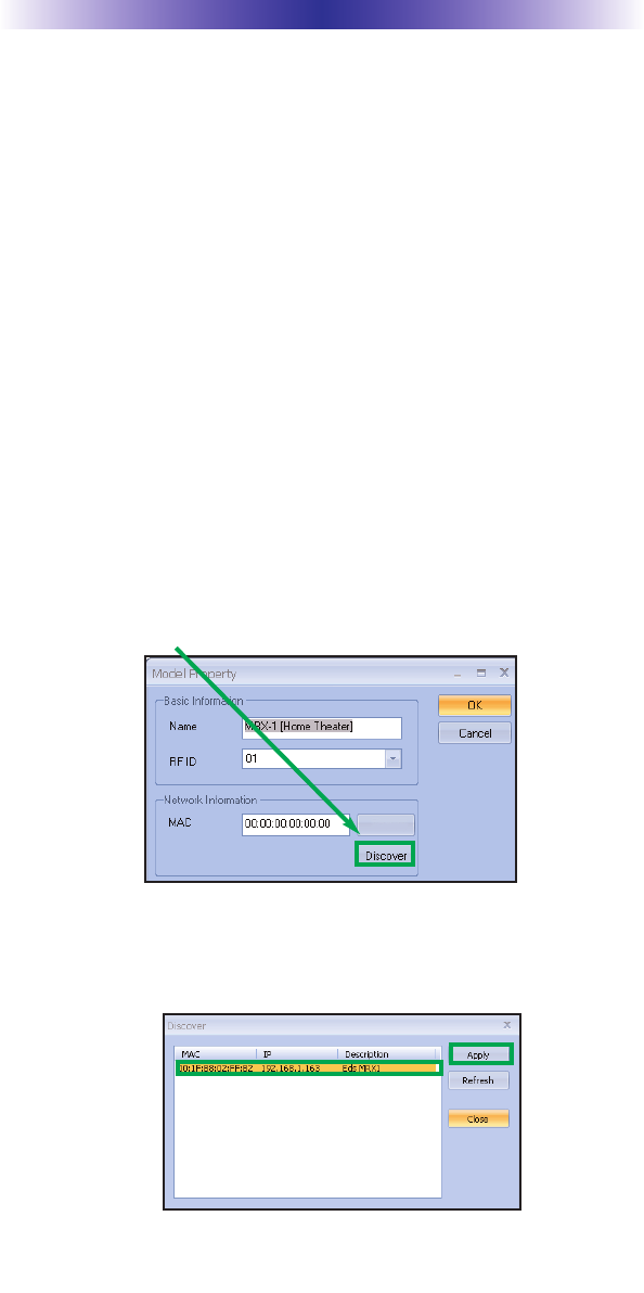
4. Add a MRX-1 base station and the properties window opens.
5. Either type in the MAC address which can be found on a sticker
located on the bottom of the unit or click on the Discover but-
ton.
6. The Discover window opens to reveal a list of connected MRX-1
units. Highlight the preferred MRX-1 MAC address and select
Apply. The Discover window closes.
MRX-1 BASE STATION
The MRX-1 is a network base station that allows full control of your
components. Once installed to the network, press a button on the
remote to send a command via WiFi over the customer’s network.
The MRX-1 receives and sends IR, RS232 and Relay commands to
the devices you specify. Note that the MRX-1 sensor can only be
utilized by URC Network Controls.
Status
Page 4
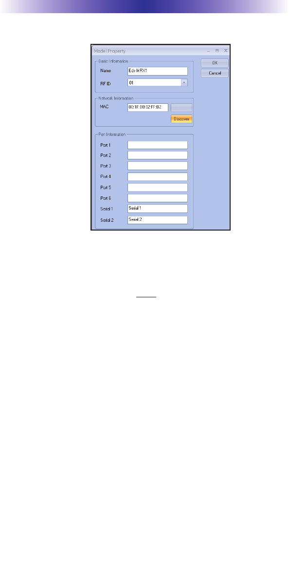
7. Now the MRX-1’s MAC address will populate the MAC address
field.
8. Press OK to close the window.
9. Plug flashers into any of the six flasher ports on the MRX-1. If
you utilize IR output #6, you must use the pink sleeved flasher.
IR Output #6 is dual purpose, it can be used as an IR flasher or it
can control the RFTX-1 for URC Lighting.
MRX-1 BASE STATION
Status
Page 5
IR Over Narrow Band via Optional RFX-250
Note: RF remotes via RFX-250 can only control IR components.
RS232, Relay and Sensor control are not available to RF remotes.
1. Power on all AV components, lower all dimmers to 50% and
power on anything that may create RF Interference (particularly
devices with high speed microprocessors or hard drives).
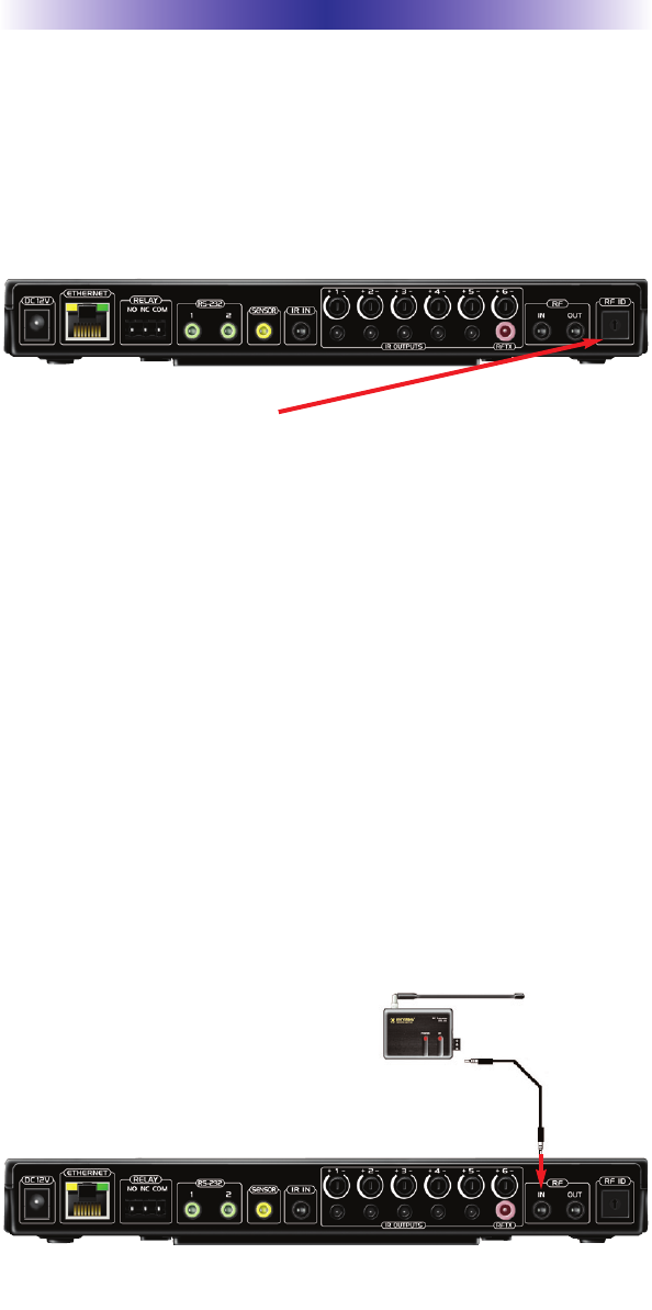
2. Check that the address wheel on the back of the MRX-1 is set to
ID#0 (the interference “sniffing” position).
Check that the arrow pointer in the center of the wheel is pointed to 0, the
default “interference sniffing” position. If it is not, use the included small
flat blade screwdriver to set the RF ID# to 0.
3. Connect the MRX-1 to its DC wall adapter and plug the wall
adapter into a live AC outlet. Place the MRX-1 in a convenient
central location in the equipment rack. Unlike an MRF-250, the
MRX-1 can be placed next to components with hard drives or
high speed microprocessors. There is no RF circuitry inside the
MRX-1 itself.
4. Connect the RFX-250 to the MRX-1’s RF INPUT jack as shown.
MRX-1 BASE STATION
When connecting a single RFX-250 to the MRX-1 utilize the cable with 3.5
mm plugs on both ends. When you need a longer wire or are connecting
up to three RFX-250s, use a cable with tinned ends or splice it. Cable can
be extended as much as 200’, then connected to the spliced end of a
3.5mm cable.

Page 6
MRX-1 BASE STATION
5. Observe the RF LED of the RFX-250. Cup your hand over the
RFX-250’s RF LED. If it is glowing or flickering you must relocate
the RFX-250 to a location where the LED does not flicker.
6. Observe the STATUS LED of the MRX-1. It is a little more sensi-
tive than the RFX-250. If you see any flickering of this LED, move
the RFX-250 to a new location. If your installation location sim-
ply doesn’t offer you any choice and you are detecting interfer-
ence everywhere you place the RFX-250, you have three last
resort options:
a. Remove the RFX-250’s antenna. This will reduce the
range enormously, but may still be enough for this client.
b. Extend a wire to another room. Try this over the floor
first, before attempting to conceal the wire.
c. Admit defeat and install a “pointing again” IR repeater
system. If no buttons are pressed on any remote control,
no valid RF transmissions are being received.
7. Once you have found a location that is absolutely clean with all
components on, test to see if the range is adequate and that
macro reliability is perfect. Start with the antenna angle set to 45
degrees and positioned so that the long side of the antenna is fac-
ing the customer’s favorite seating position. When testing, set
both the remote and the MRX-1 to the same VALID RF ID#. Keep
in mind that zero (0) is not a valid RFID#. Watch the STATUS
LED on MRX-1 - it should light every time you press a button on
the remote. This will tell you that the signal was received and
understood. You can ignore the RF LED on the RFX-250 (it only
indicates that a signal was received, not that it was understood).
8. If the range is inadequate, you may extend the wire to any area
that is not getting good results and place an additional RFX-250
in that area. Up to three RFX-250s can be connected to one
MRX-1.
9. Should you need more than six IR Outputs, connect as many as
three different MRX-1s to one RFX-250 in a daisy chain using the
supplied cable. To preserve addressability, set each MRX-1 to a
different RF ID number. Remember “0” (zero) is not a valid RF
ID.

Page 7
MRX-1 BASE STATION
Optimizing IR Flasher Levels
Test a few commands for each device before fixing the flasher in
place on the front panel of a device.
Since TiVo, Replay TV, Satellite Receivers and Cable Boxes are all
extremely sensitive to IR overload or saturation, you should test
them thoroughly. Put up the on screen guide and test the navigation
arrows. Compare operation via RF to the original remote control.
Operation should be identical. If operation is inconsistent or slug-
gish, lower the IR line output and/or reposition the flasher.
If you still have sluggish operation, check that the remote control is
set to a particular LINE OUT, rather than ALL. When IR commands
are sent to all the flashers in a cabinet, you can have difficulty
adjusting the IR Output. Reprogram the remote control to send IR
commands only via a specific (1-6) Line Output, then readjust the
IR Line Output level.
1. Connect an IR emitter to each IR output and run the emitter
wire to the front panel of each component. DO NOT STICK the
emitter in place. ADJUST the level first.
2. Adjust each of the IR Output levels for best operation. If the
component operates best at minimum level, but is still operating
sluggishly or intermittently, move the emitter farther away from
the components IR sensor.
Page 8
MRX-1 BASE STATION
Integrating Optional RFTX-1 to control URC
Lighting
Not only will you have greater control of your home theatre equip-
ment with the MRX-1, now you also have control of your URC
Lighting. What better way to watch a movie and control your uni-
verse!
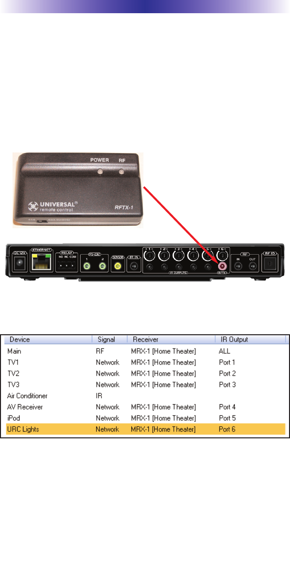
1. Simply plug the RFTX-1 with the 10’ pink connecting cable
(included with the RFTX-1) into the MRX-1 pink fixed port #6.
2. Set the URC Lighting Device in the CCP Editor to RF and set the
IR output to Port #6.
3. Download to the MX remote and begin controlling your lights.
Page 9
MRX-1 BASE STATION
Overview of IR Routing
There are several considerations to take into account when you are
installing an MRX-1 to control an array of identical components:
1. Each identical component must receive IR commands ONLY
from a dedicated Flasher affixed to its front panel or a rear panel
direct IR input. The SIGNAL of the remote should be set to
Network or RF ONLY for each identical component. IR can still
be utilized for other devices in your system!
2. When connecting a flasher from the MRX-1 to your component
make sure to notate the Flasher Output Number being used.
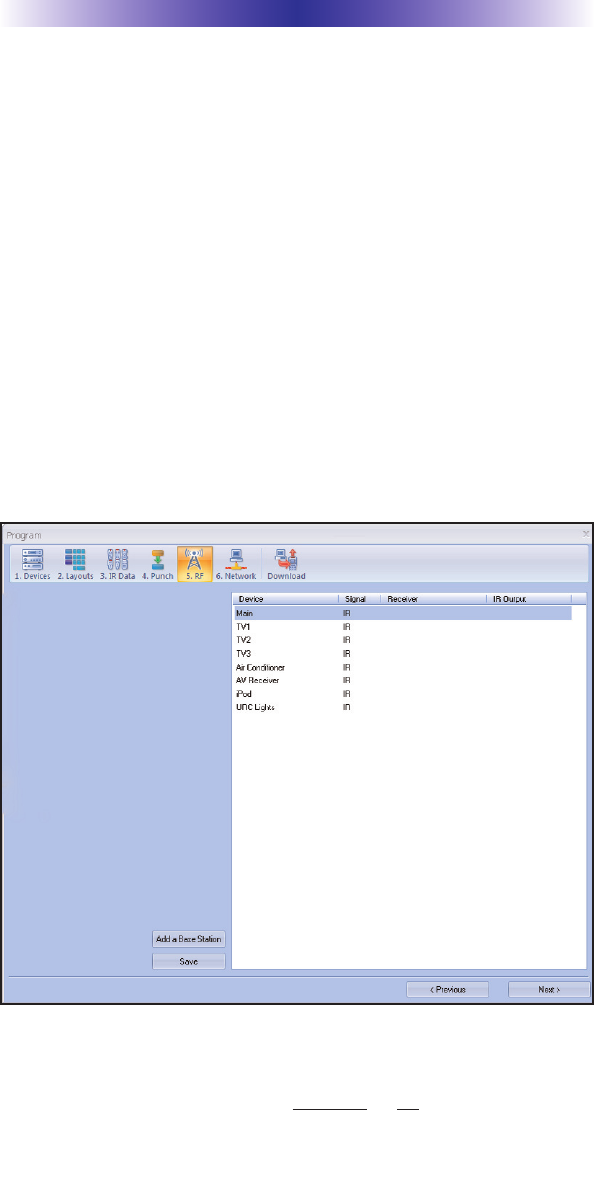
Network or RF Setup in CCP
1. Open the RF Setup Window in CCP
The RF Setup window opens after selecting RF Control from the
Program Menu. The RF Setup window is composed of a “spread
sheet” of options for EACH of your devices.
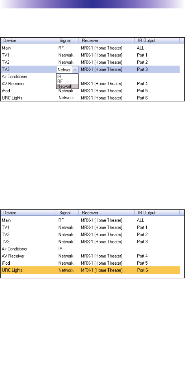
2. Adjust the Signal For Each of the Identical Devices
The RF Setup window enables you to adjust the Signal output for
each device individually, by clicking on the intersection of a row
and a column and then selecting Network or RF (for optional RFX-
250) from the three options shown in the pull down list box.
Page 10
MRX-1 BASE STATION
Select Network or RF (for optional RFX-250) from the three
options shown for EACH of the identical TVs. You may leave the
other components with no flashers set to IR.
3. Select a Receiver to Control Identical Devices
Choose a Base station to send commands over the Network or via
RF to control multiple components.
4. Adjust the IR Outputs For Each of the Identical Devices
The RF Setup window enables you to adjust which Flashers output
by the remote control for each device individually, by clicking on
the intersection of a row and a column and then selecting Ports 1-6
from the seven options shown in the pull down list box.
Select the correct IR Output (refer to your connection notes) for
EACH of the identical TVs. You may leave the other components of
the system set to ALL. In the figure below, each device is set to a
specific flasher.
5. Close the RF window and Download to the Remote.

Page 11
MRX-1 BASE STATION
Frequently Asked Questions
Can I use flasher/emitters that I have already installed in the sys-
tem to connect to the MRX-1?
Yes, the flashers are compatible if they use 3.5mm plugs with the
same polarity (Tip is data, sleeve is ground). It is important to notate
the RFTX-1 shared port utilizes a sleeved emitter for long term use.
I’m getting inconsistent operation regardless of flasher level or
position.
Some components are easily overloaded with IR from nearby flashers.
Prevent IR from affecting the problem component from other flashers by
setting the device to a specific IR Line Output instead of ALL, then adjust
the Line Output.
I am unable to control my URC Lighting Dimmer/Switch with the
MRX-1. Now what?
Make sure the RF switch on the RFTX-1 is set to the correct fre-
quency for the URC Dimmer or Switch. URC Lighting Models
MRFA is 418MHz and MRFB is 433MHz.
How do I update the firmware?
Make sure the MRX-1 is connected to the Network then open CCP
and click on the Firmware button located
How can I set my MRX-1 to factory default?
Look on the bottom of the MRX-1 and remove the cover plate to
reveal a reset button. Simply press the button with a pen or thin
object to reset the unit.
Specifications
Network: One 10/100 Ethernet port
Relay: One relay configurable to be NO, NC or Momentary
Sensor: One sensor supports Video or Voltage sensing via URC sen-
sors.
RS-232: Two RS-232 ports support TX, RX and GND two way com-
munication via URC cables.
IR: Six adjustable IR ports enable the included URC emitters to
control IR devices Note: 6th IR Output requires the included
sleeved emitter (identified by a pink connector), since it can option-
ally be used to connect an RFTX-1
Weight: 8.4 oz.
Size: 248 x 120mm x28mm
Power: 12v External Power Supply

Page 12
USA Limited Warranty Statement
Your Universal Remote Control, when delivered to you in new
condition, is warranted against defects in materials or work-
manship as follows: UNIVERSAL REMOTE CONTROL, INC.
warrants this product against defects in material or workman-
ship for a period of one (1) year and as set forth below.
Universal Remote Control will, at its sole option, repair the
product using new or comparable rebuilt parts, or exchange the
product for a comparable new or rebuilt product. In the event
of a defect, these are your exclusive remedies.
This Limited Warranty covers only the hardware components
packaged with the Product. It does not cover technical assis-
tance for hardware or software usage and it does not cover any
software products whether or not contained in the Product; any
such software is provided "AS IS" unless expressly provided for
in any enclosed software Limited Warranty.
To obtain warranty service, you must deliver the product,
freight prepaid, in its original packaging or packaging affording
adequate protection to Universal Remote Control at the address
provided in the Owner's Manual. It is your responsibility to
backup any macro programming, artwork, software or other
materials that may have been programmed into your unit. It is
likely that such data, software, or other materials will be lost
during service and Universal Remote Control will not be
responsible for any such damage or loss. A dated purchase
receipt, Bill of Sale, Installation Contract or other verifiable
Proof of Purchase is required. For product support and other
important information visit Universal Remote Control's website:
http://www.UniversalRemoteControl.com or call the Universal
Remote Control Customer Service Center (914) 835-4484.
This Limited Warranty only covers product issues caused by
defects in material or workmanship during ordinary consumer
use. It does not cover product issues caused by any other rea-
son, including but not limited to product issues due to commer-
cial use, acts of God, third-party installation, misuse, limita-
tions of technology, or modification of or to any part of the
Universal Remote Control product. This Limited Warranty does
not cover Universal Remote Control products sold as USED, AS
IS, REFURBISHED, so-called "B STOCK" or consumables (such
as batteries). This Limited Warranty is invalid if the factory-
applied serial number has been altered or removed from the
product. This Limited Warranty is valid only in the United States
of America. This Limited Warranty specifically excludes prod-
ucts sold by unauthorized resellers.
MRX-1 BASE STATION

Page 13
This equipment has been tested and found to comply with
the limits for a Class B digital device, pursuant to part 15 of
the FCC Rules. These limits are designed to provide reason-
able protection against harmful interference in a residential
installation. This equipment generates, uses and can radiate
radio frequency energy and, if not installed and used in
accordance with the instructions, may cause harmful interfer-
ence to radio communications.
However, there is no guarantee that interference will not
occur in a particular installation. If this equipment does cause
harmful interference to radio or television reception, which
can be determined by turning the equipment off and on, the
user is encouraged to try to correct the interference by one
more of the following measures:
Reorient or relocate the receiving antenna.
Increase the separation between the equipment and
receiver.
Connect the equipment into an outlet on a circuit dif-
ferent from that to which the receiver is connected.
Consult the dealer or an experienced radio/TV techni-
cian for help.
Warning
Changes or modifications not expressly approved by the manu-
facturer could void the user's authority to operate the equip-
ment.
Note : The manufacturer is not responsible for any Radio or TV
interference caused by unauthorized modifications to this
equipment. Such modifications could void the user's authority
to operate the equipment.
Information To The User
MRX-1 BASE STATION

Page 14
MEMO

Page 15
MEMO

Page 16
MEMO
500 Mamaroneck Avenue, Harrison, NY 10528
Phone: (914) 835-4484 Fax: (914) 835-4532
www.universalremote.com
OCE-0076A Rev.01