Ohsung Electronics URCMRX10 Network Base Station User Manual H Users manual
Ohsung Electronics Co., Ltd. Network Base Station H Users manual
User Manual

Order Number : GETEC-C1-10-181 FCC Part 15 subpart C
Test Report Number : GETEC-E3-10-093 Page 1 / 1
EUT Type: RF Remote Controller
FCC ID.: OZ5URCMRX10
APPENDIX H
: USER’S MANUAL
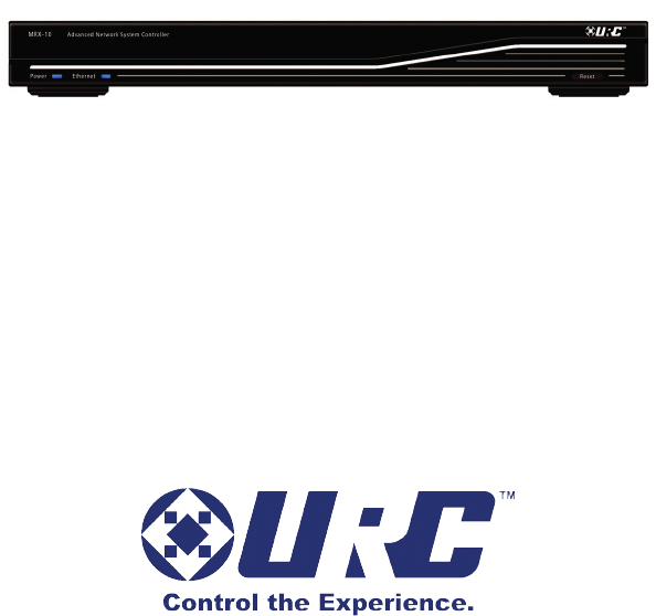
MRX-10 Owners Manual
Advanced Network ystem
Controller

MRX-10 Owners Manual ©2010 Universal Remote Control,Inc.
The information in this manual is copyright protected.No part of this man-ual
may be copied or reproduced in any form without prior written consentfrom
Universal Remote Control,Inc.
UNIVERSAL REMOTE CONTROL,INC.SHALL NOT BE LIABLE FOR OPER-
ATIONAL,TECHNICAL OR EDITORIAL ERRORS/OMISSIONS MADE IN
THIS MANUAL.
The information in this manual may be subject to change without prior
notice.
Complete Control is a registered trademark of Universal Remote Control,Inc.
All other brand or product names are trademarks or registered trademarks
of their respective companies or organizations.
Universal Remote Control,Inc.
500 Mamaroneck Avenue, Harrison, NY 10528
Phone: (914) 835-4484 Fax: (914) 835-4532

THEDIGITALMULTIZONEAMPLIFIER
Introduction 1
Features and Benefits 1
Parts Guide 1
Front and Rear Panel Descriptions 2
Specifications 4
USA Limited Warranty Statement 9
Federal Communication Commission
Interference Statement 10
Regulatory Information to the user 11
Declaration of Conformity 12

Page 1
MRX-10 ADVANCEDNETWORKSYSTEMCONTROLLER
Introduction
The MRX-10 Advanced Network System Controller controls all
MRX series connected devices throughout the entire home. Press a
button on a Total Control remote or keypad to issue a command
from the MRX-10 to turn off the lights in every room all while
watching a movie. View the artist name, song title and album art
your child is listening to in their room from a Total Control remote
or keypad. Also control whole house music from sources such as a
DMS-1200, DMS-100, SNP-1 and a PSX-2.
Features and Benefits
Stores and issues commands and macros for all IP, IR, RS-
232, Relay, Sensor and 12V controlled devices to MRX series
base stations in one system
Provides 2-Way communication with Total Control remotes
and keypads
Control URC Lighting with an optional RFTX-1 RF Transmitter
Can be programmed off premises via the internet
Easy rack-mounting via optional RMK-1 rack mounting kit.
Parts Guide
The MRX-10 Advanced Network System Controller includes:
1 - MRX-10 Network System 1 - Ethernet Cable
1 - AC Power Adapter 8 - IR Emitters with standard 3.5mm
1 - Power Cord plugs
1 - Adjustment Tool 1 - InstallationManual
Page 2
MRX-10 ADVANCEDNETWORKSYSTEMCONTROLLER
Front and Rear Panel Descriptions
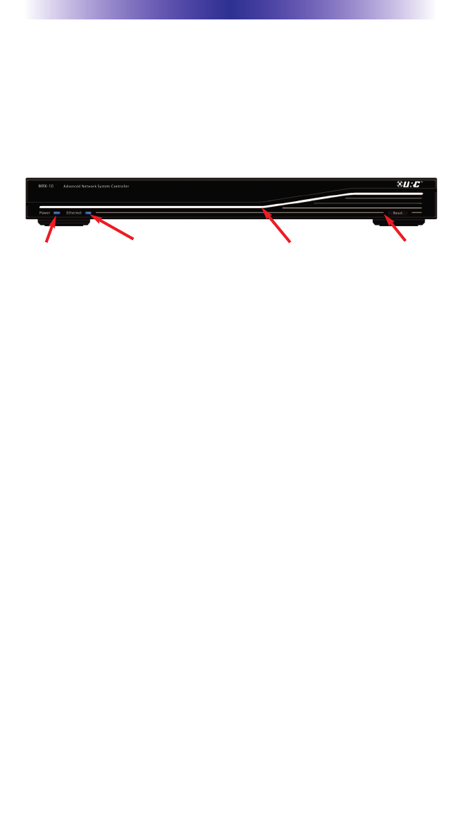
Front Panel
The front panel consists of 2 indicator lights which will illuminate
when in use.
Power LED: Indicates that the MRX-10 is powered on when lit.
Ethernet LED:Indicates the network connectivity status of the MRX-
10. On=Connected, Off=not connected.
Total Control Illumination: Attractive, adjustable accent lighting.
Reset: Press for one second and release to reboot the MRX-10.
Power LED ResetEthernet LED Total Control llumination
Page 3
MRX-10 ADVANCEDNETWORKSYSTEMCONTROLLER
Rear Panel
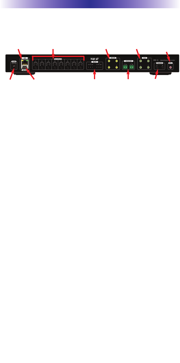
The rear panel ports are:
DC 12V Power: Attach the included 12V DC 3.5A power supply
here.
LAN Connection: RJ45 standard 10/100 Ethernet connection to the
local network.
URC USB Port: USB port for future expansion
IROutputs: Eight standard 3.5mm IR emitter ports with individual
output level adjustment screws.
Relays NO, NC, COM: Two programmable relays to be normally
opened (NO), normally closed (NC) or momentary contacts. An
application should be less than 30V/.5A.
Sensors: Four sensor ports allow programming of state dependent
and triggered macros. Compatible with URCVideo (URC part: VID)
and voltage (URC part: VS-100) sensors.
12V OUT: Two programmable 12V/0.2A outputs. Each may be pro-
grammed to turn on, off or momentarily toggle its output.
RS-232: Four RS-232 ports support Tx(Transmit), Rx(Receive) and
GND(Ground) connections for two way communication.
Compatible with URC cables RS232F and RS232M.
Trigger In: IR and RFtrigger input ports allow integration with other
control systems and remotes.
RFTX-1: Attach an optional RFTX-1 transmitter to control URC
Lighting products via 418MHz or 433.92MHz wireless RF.
DC 12V
Power
URC
USB
Relay:NO,
NC, COM
12V Out Trigger In
RFTX-1
RS-232
PortsSensorsIROutputs: #1-8LAN

Page 4
MRX-10 ADVANCEDNETWORKSYSTEMCONTROLLER
Specifications
Input & Outputs:
12V/.2A: Two (Programmable)
IR: Eight adjustable output
USB: One (for future use)
Ethernet: One 10/100 RJ45 port (Indicator 2LED)
RS-232: Four, supporting TX, RX and GND.
Sensor: Four, supporting Video or Voltage sensing (requires URC
sensors).
Relays: NO, NC or COM
RF:
Frequency: 2.4GHz (for MS-780)
Range: 50 to 100 feet, depending upon the environment
Power Supply: 12v DC 3.5A External Power Supply
Size: 1.7" x 17" x 8.7" (H X W x D
Weight: 4.5 lbs. (2.05 Kg)

Page 5
MRX-10 ADVANCEDNETWORKSYSTEMCONTROLLER
USA Limited Warranty Statement
Your Universal Remote Control, when delivered to you in new
condition, is warranted against defects in materials or work-
manship as follows: UNIVERSAL REMOTE CONTROL, INC.
warrants this product against defects in material or workman-
ship for a period of one (1) year and as set forth below.
Universal Remote Control will, at its sole option, repair the
product using new or comparable rebuilt parts, or exchange the
product for a comparable new or rebuilt product. In the event
of a defect, these are your exclusive remedies.
This Limited Warranty covers only the hardware components
packaged with the Product. It does not cover technical assis-
tance for hardware or software usage and it does not cover any
software products whether or not contained in the Product; any
such software is provided "AS IS" unless expressly provided for
in any enclosed software Limited Warranty.
To obtain warranty service, you must deliver the product,
freight prepaid, in its original packaging or packaging affording
adequate protection to Universal Remote Control at the address
provided in the Owner's Manual. It is your responsibility to
backup any macro programming, artwork, software or other
materials that may have been programmed into your unit. It is
likely that such data, software, or other materials will be lost
during service and Universal Remote Control will not be
responsible for any such damage or loss. A dated purchase
receipt, Bill of Sale, Installation Contract or other verifiable
Proof of Purchase is required. For product support and other
important information visit Universal Remote Control's website:
http://www.UniversalRemoteControl.com or call the Universal
Remote Control Customer Service Center (914) 835-4484.
This Limited Warranty only covers product issues caused by
defects in material or workmanship during ordinary consumer
use. It does not cover product issues caused by any other rea-
son, including but not limited to product issues due to commer-
cial use, acts of God, third-party installation, misuse, limita-
tions of technology, or modification of or to any part of the
Universal Remote Control product. This Limited Warranty does
not cover Universal Remote Control products sold as USED, AS
IS, REFURBISHED, so-called "B STOCK" or consumables (such
as batteries). This Limited Warranty is invalid if the factory-
applied serial number has been altered or removed from the
product. This Limited Warranty is valid only in the United States
of America. This Limited Warranty specifically excludes prod-
ucts sold by unauthorized resellers.

Page 6
MRX-10 ADVANCEDNETWORKSYSTEMCONTROLLER
Federal Communication Commission
Interference Statement
This equipment has been tested and found to comply with the limits for a Class
B digital device, pursuant to part 15 of the FCC Rules. These limits are
designed to provide reasonable protection against harmful interference in a res-
idential installation. This equipment generates, uses and can radiate radio fre-
quency energy and, if not installed and used in accordance with the instruc-
tions, may cause harmful interference to radio communications. However,
there is no guarantee that interference will not occur in a particular installation.
If this equipment does cause harmful interference to radio or television recep-
tion, which can be determined by turning the equipment off and on, the user is
encouraged to try to correct the interference by one more of the following
measures:
Reorient or relocate the receiving antenna.
Increase the separation between the equipment and receiver.
Connect the equipment into an outlet on a circuit different from
that to which the receiver is connected.
Consult the dealer or an experienced radio/TV technician for
help.
Warning!
Changes or modifications not expressly approved by the manufacturer could
void the user's authority to operate the equipment.
Note : The manufacturer is not responsible for any Radio or TV interference
caused by unauthorized modifications to this equipment. Such modifications
could void the user's authority to operate the equipment.
FCC Caution
This device complies with Part 15 of the FCC Rules. Operation is subject to the
following two conditions: (1) this device may not cause harmful interference,
and (2) this device must accept any interference received, including interference
that may cause undesired operation.
Any changes or modifications not expressly approved by the party responsible
for compliance could void the authority to operate equipment.
The antenna(s) used for this transmitter must not be co-located or operating in
conjunction with any other antenna or transmitter.
Federal Communication Commission (FCC) Radiation Exposure Statement
The device and the antenna for this device must be installed to ensure a
minimum separation distance of 20 cm or more from a person's body. Other
operating configurations should be avoided.
Page 7
MRX-10 ADVANCEDNETWORKSYSTEMCONTROLLER
Regulatory Information to the user
CE conformity Notice
Products with “CE” marking comply with the R&TTE Directive
1995/5/EC, EMC Directive 2004/108/EC and Low Voltage
Directive 2006/95/EEC issued by the commission of the European
Community.
1) R&TTE Directive
LVD : EN 60950-1
EMC : ETSI EN 301 489-1,3
RF : ETSI EN 300 220-1,2
: ETSI EN 300
2) EMC Directive
Emission : EN 55022
Immunity : EN 55024
Power : EN-61000-3-2, 3
Safety instruction for charging internal rechargeable battery of
remote control Caution
Use only with EN60950-1 approved as Limited power source and
double insulation( ) marked power adaptor & same ratings
described on the product label (12Vdc,3.5A).
Declaration of Conformity
“Hereby, Universal Remote Control Inc. declares that this MRX-10 is
in compliance with the Essential requirements and other relevant pro-
visions of Directive 1999/5/EC.”
Certification
Type No.(Model No.) MRX-10
Batch/Serial No. -
Power Rating 12V 3.5A
Frequency band 2.45GHz (ZigBee-Pro)

Page 8
MRX-10 ADVANCEDNETWORKSYSTEMCONTROLLER
Declaration of Conformity
Company Name : Universal Remote Control Inc.
Company Address : 500Mamaroneck Avenue, Harrison, NY 10528, U.S.A
Contact Info rmation : www.universalremote.com
Phone: (914)835-4484 Fax: (914)835-4532
Brand Name : UNIVERSAL remote control
Product Name : NETWORK BASE STATION
Model Name : MRX-10
This product herewith complies with the requirements of EMC Directive (2004/108/EC)
and R&TTE Directive(1995/5/EC) issued bythe Commission of the European Community
Compliance with these directives implies conformity to the following European Community
EMC Directive
EN 55022
EN 55024
EN 61000-3-2
EN 61000-3-3
R&TTE Directive
EN 60950-1
ETSI EN 301-489-1,3
ETSI EN 300 220-1,2
ETSI EN 300
List of test reports and/or certificate verified compliance with the standards above
Date of issue : November 30, 2010
Name and signature of authorized person :
EMC Directive
Report No.
Testi ng Labora tory : Gumi College EMC Center
R&TTE Directive
Certificate No.
Certificate Body : TUV Rheinland (No. 0197)
James Novak
Senior Product Manager
Universal Remote Control Inc.

OCE-0000A Rev 01