Ohsung Electronics URCTKP5600 Network Keypad User Manual EMISSION TEST REPORT
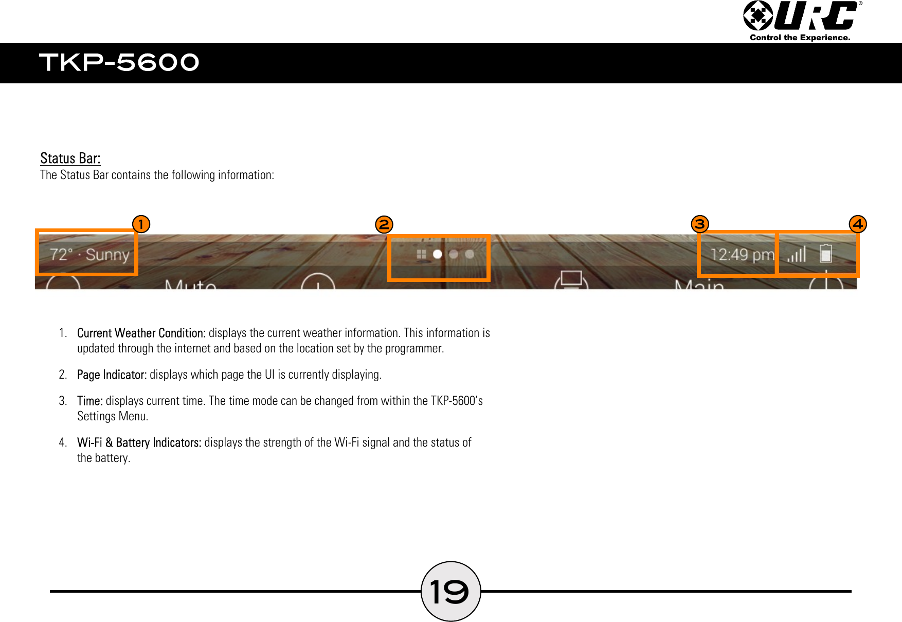
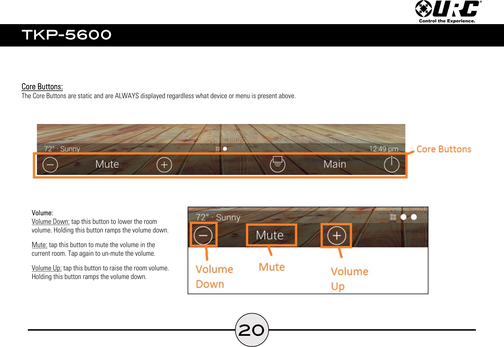
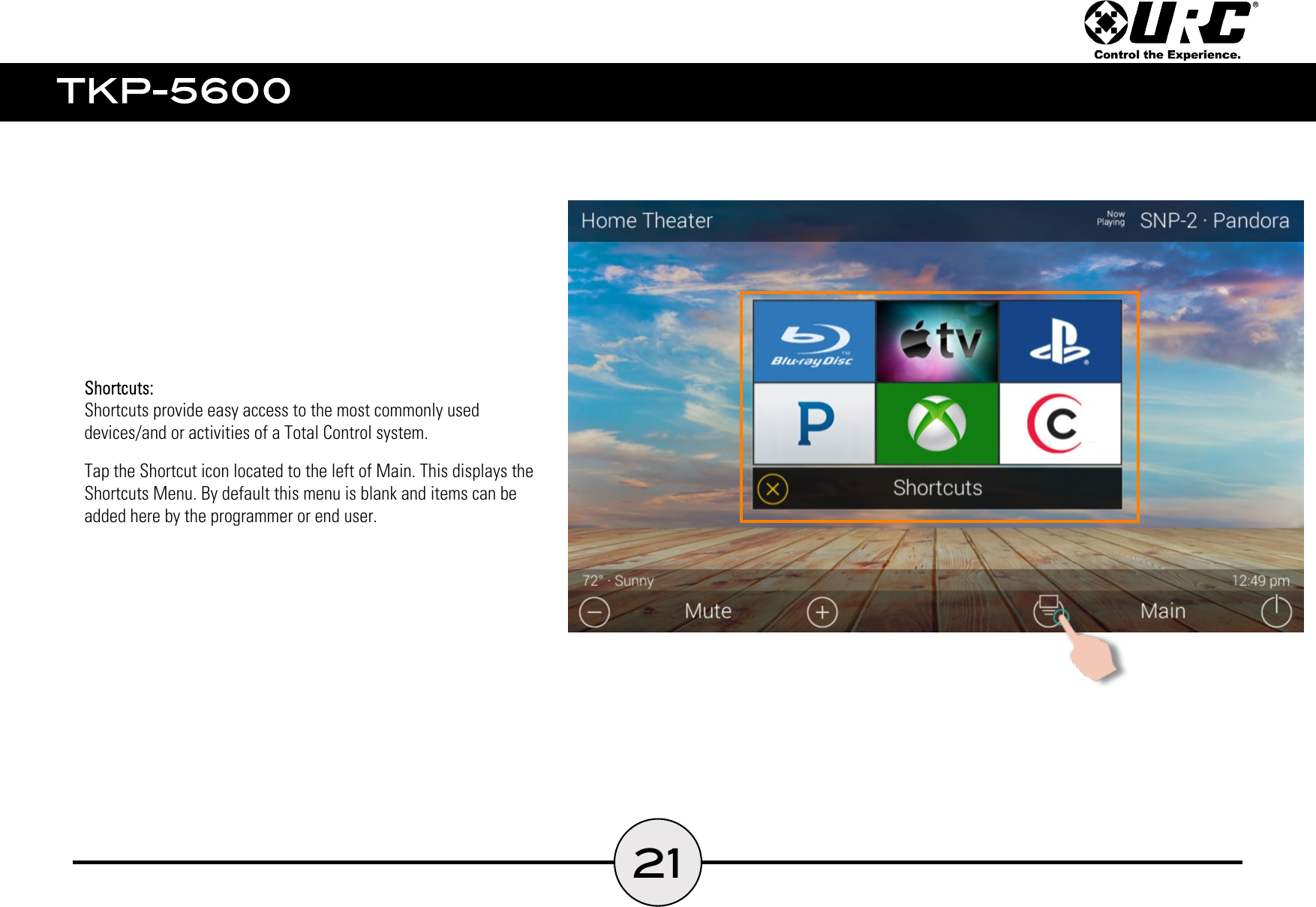
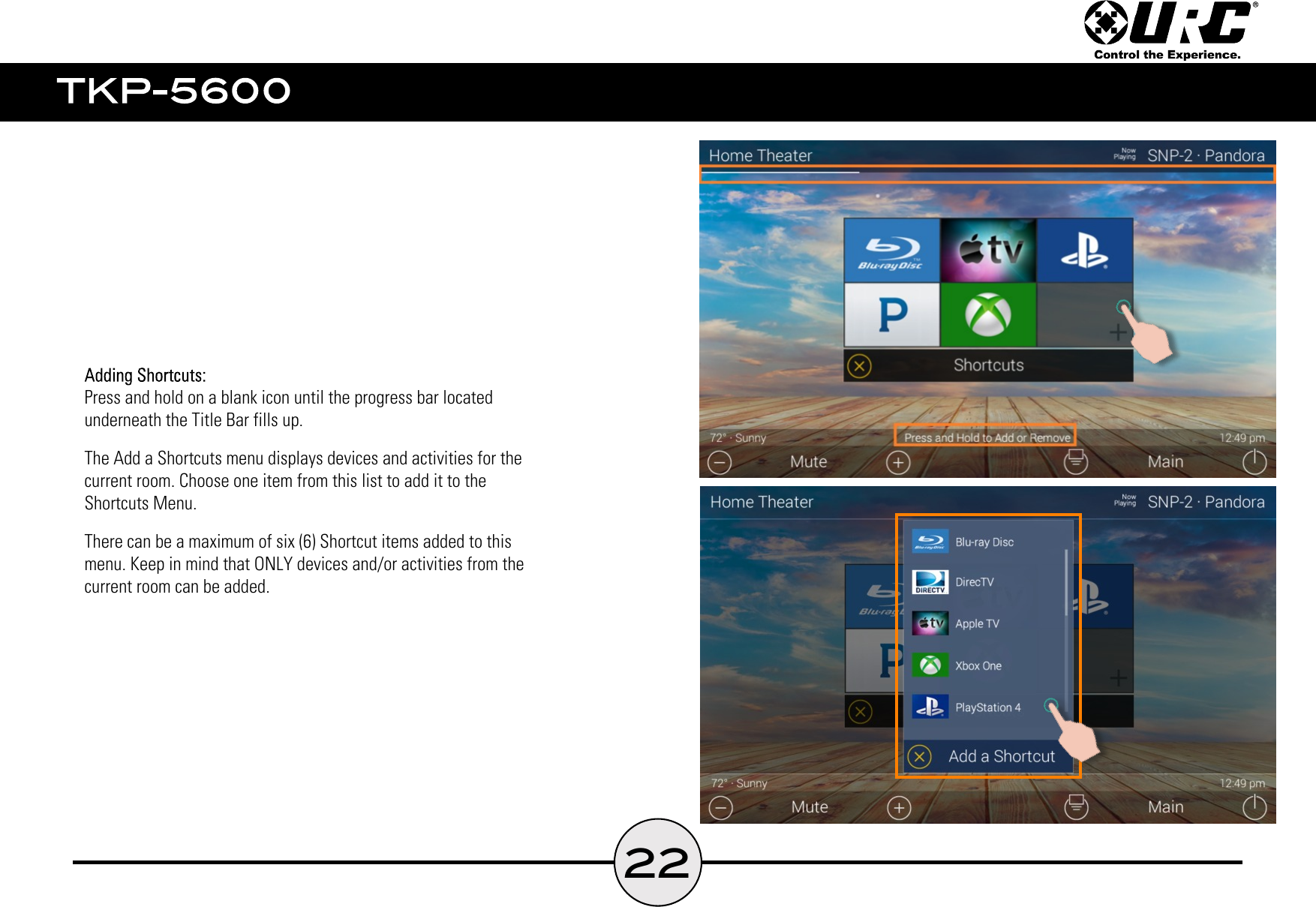
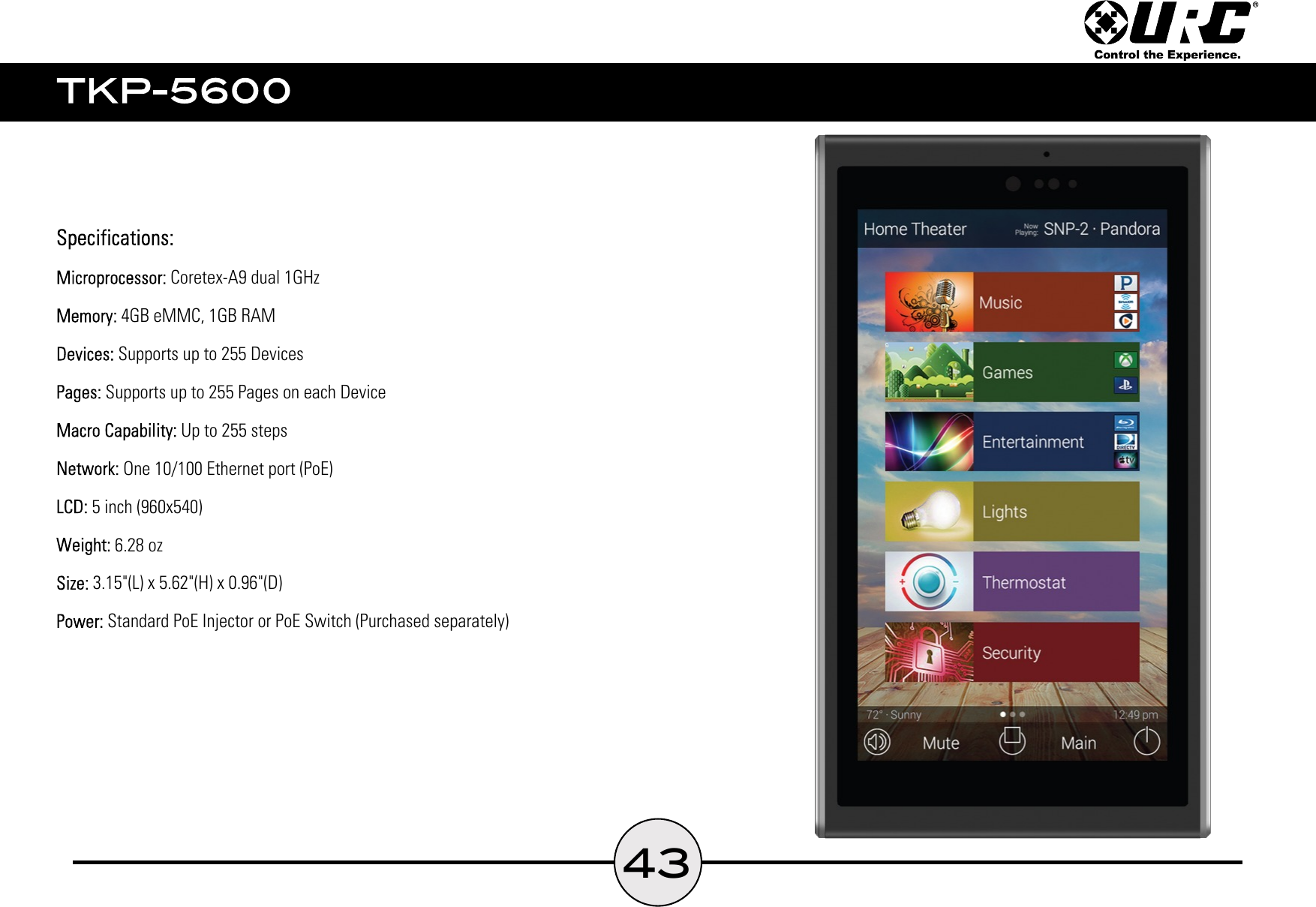
Ohsung Electronics Co., Ltd. Network Keypad EMISSION TEST REPORT
UserManual.wiki
>
Ohsung Electronics
>
URCTKP5600 User Manual
Users Manual
Navigation menu
Upload a User Manual
Namespaces
Wiki Guide
HTML
PDF
Info
Views
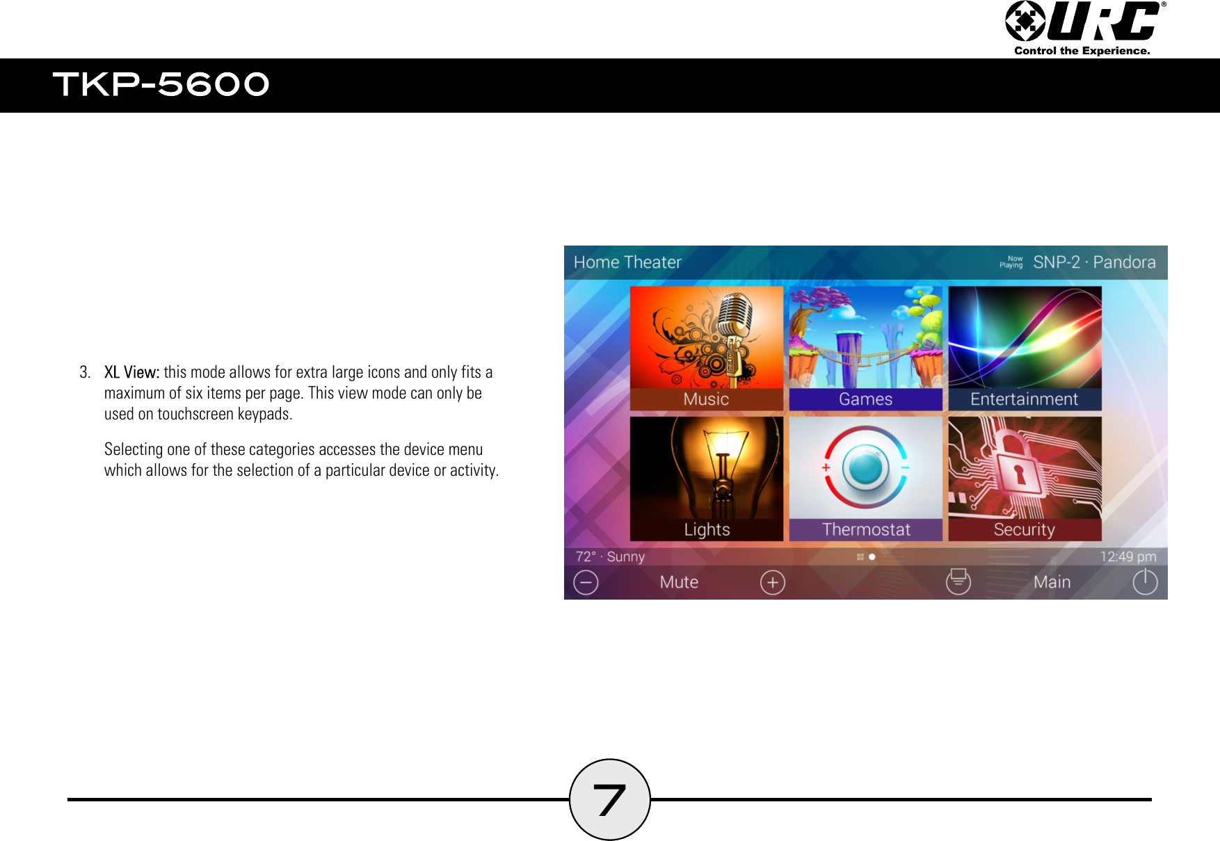
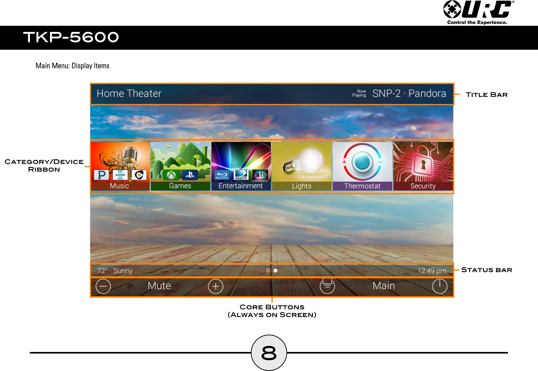
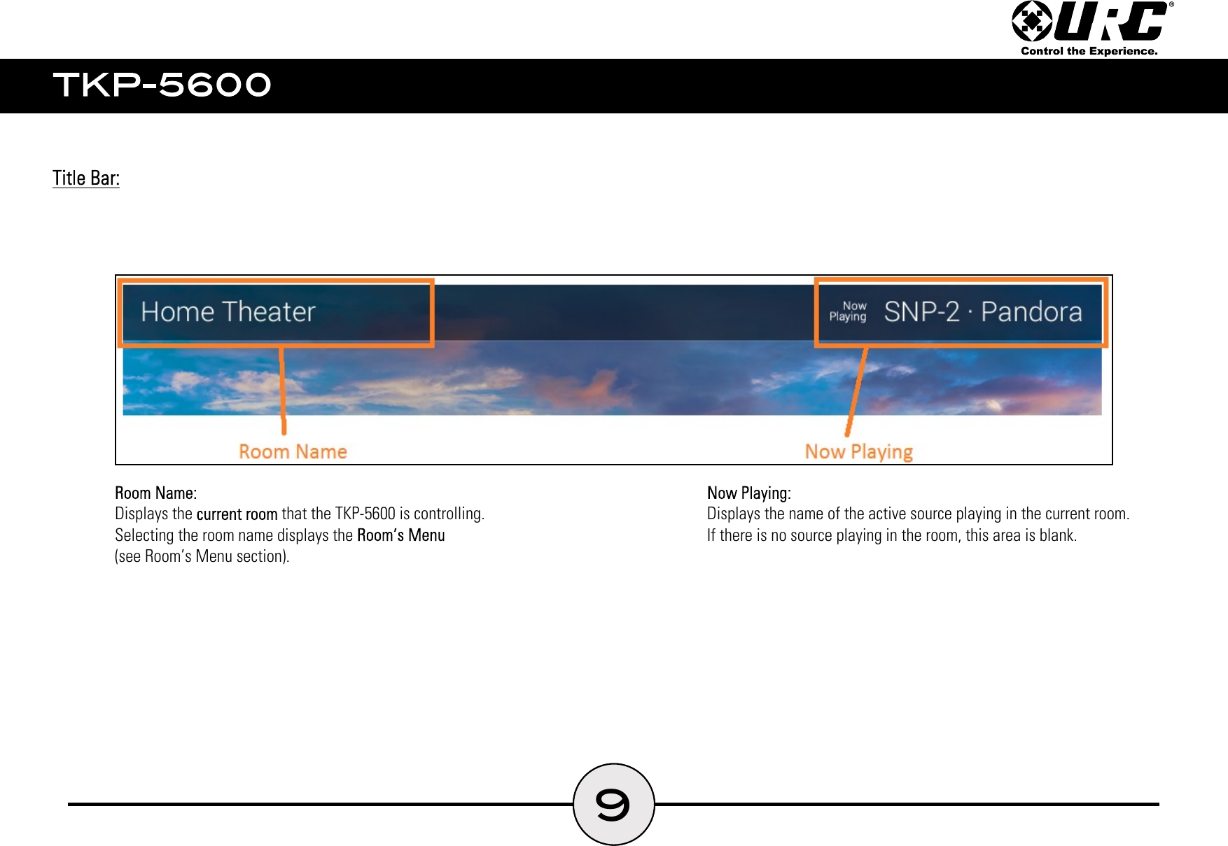
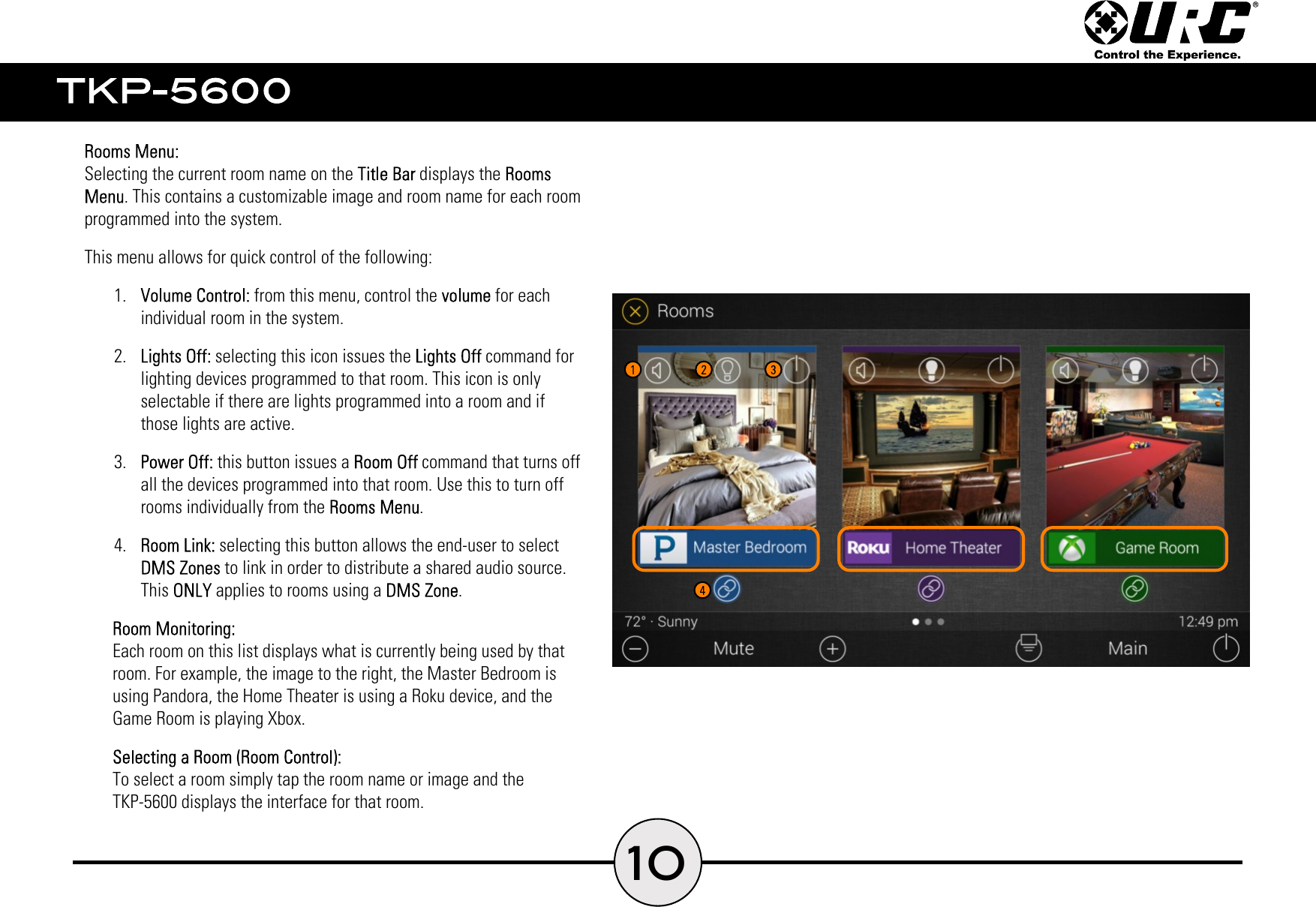
User Manual
Discussion / Help
Navigation