Ohsung Electronics URCTKP5600 Network Keypad User Manual EMISSION TEST REPORT
Ohsung Electronics Co., Ltd. Network Keypad EMISSION TEST REPORT
Users Manual

Order Number
: GETEC-C1-17-184
FCC Part 15 Certification
Test Report Number
: GETEC-E3-17-015
Page 1 / 1
EUT Type: Network Keypad
FCC ID.: OZ5URCTKP5600
APPENDIX G
: USER’S MANUAL
1
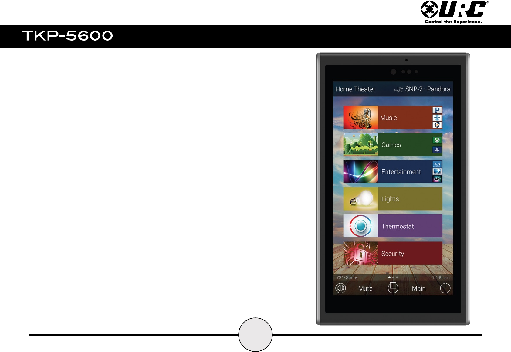
TKP-5600
Owner’s Manual
Thank you for purchasing the TKP-5600 in-wall network keypad. Its easy intuitive design
helps to simplify your life while adding control of more things than you thought possible.
Visit our home page www.UniversalRemote.com for Technical Support information, manual
downloads, and general information on URC and all of our products.
Total Control is a URC product sold direct. If you should have any questions or require any
assistance, contact your Custom Installer/Programmer prior to contacting URC support.
My Installer/Programmer:
or URC Technical Support at: techsupport@universalremote.com
(914) 835-4484
500 Mamaroneck Ave
Harrison, New York 10528
(800) 901-0800
1
1
The TKP-5600 is loaded with features to provide the perfect control and automation experience. Enjoy features such as:
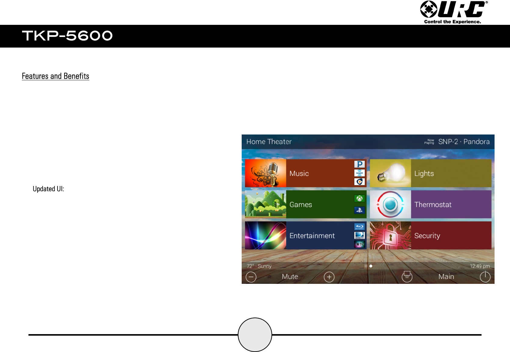
The TKP-5600 features URC’s 2.0 update that revamps the existing
user interface to a sleek modern look with customizable options.
This allows the system programmer to create beautiful interfaces with
custom backgrounds and easy to navigate menus.
●Updated UI
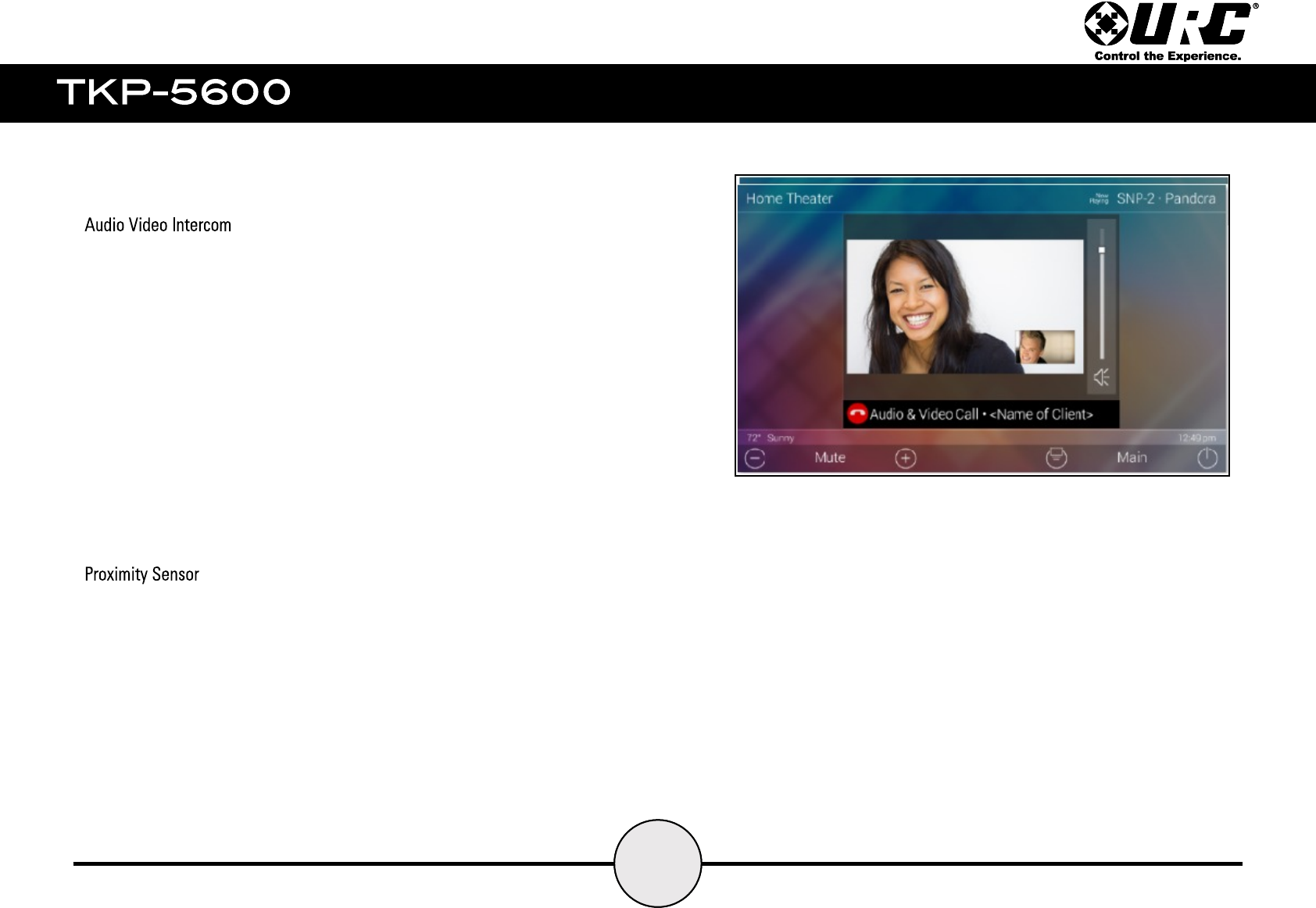
●Audio-Video Intercom
●Proximity Sensor
1
2
Easily communicate throughout the home using the Audio Video
Intercom feature. Communicate across multiple devices including other
TKP-5600’s, and/or other URC intercom enabled products. This feature
includes a baby monitor so that you can make sure the little one is
safe and sound by viewing it right on the remote.
This features allows all URC Intercom-Enabled devices to broadcast
calls throughout the home, make audio calls only, and use the built in
camera for surveillance.
The TKP-5600 comes to life and is ready for action as it automatically
senses how close you are to the keypad. Utilizing its proximity
sensor, it can detect distances from up to three (3) feet away, this
setting can be adjusted from within the Settings menu.
1
4
Included with the TKP-5600:
1x - TKP-5500
4x - Mounting Screws
1x - Mounting Plate
1x - Ethernet Cable
1
5
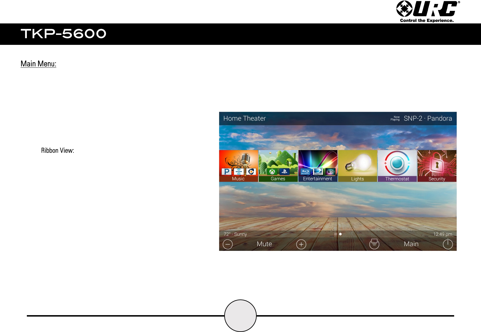
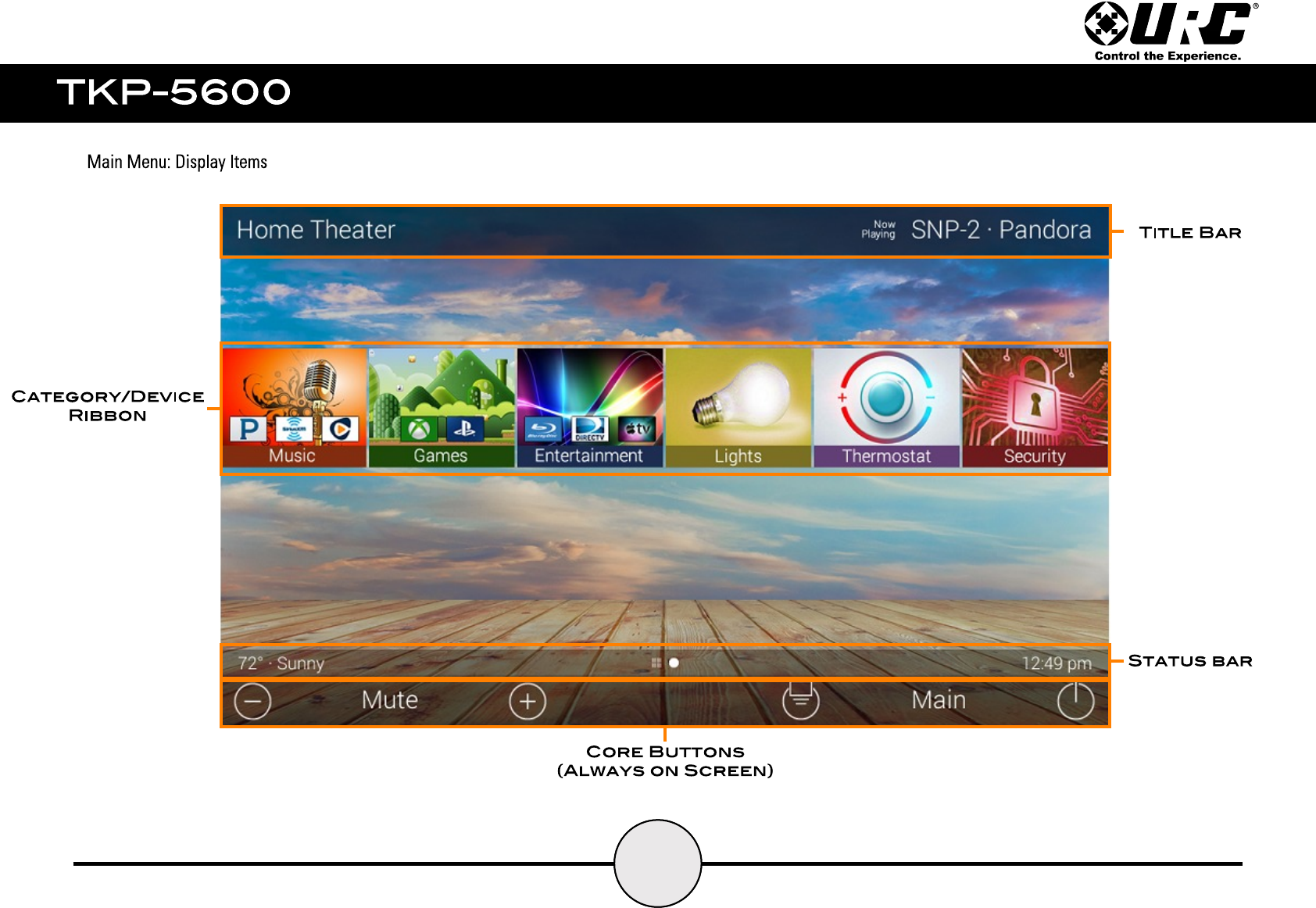
The Main Menu supports three (3) different view types. These view types can be setup only by the
system programmer from within the URC programming software. Below are the three (3) options:
1. this is the default display for all URC interfaces. It
provides up to six items per page.
All devices programmed into the system can be broken down
into categories (Music, Games, Entertainment, etc.) The can
also be left as individual devices on the Main Screen.
Selecting one of these categories displays a device menu which
allows for the selection of a particular device and/or activity.
1
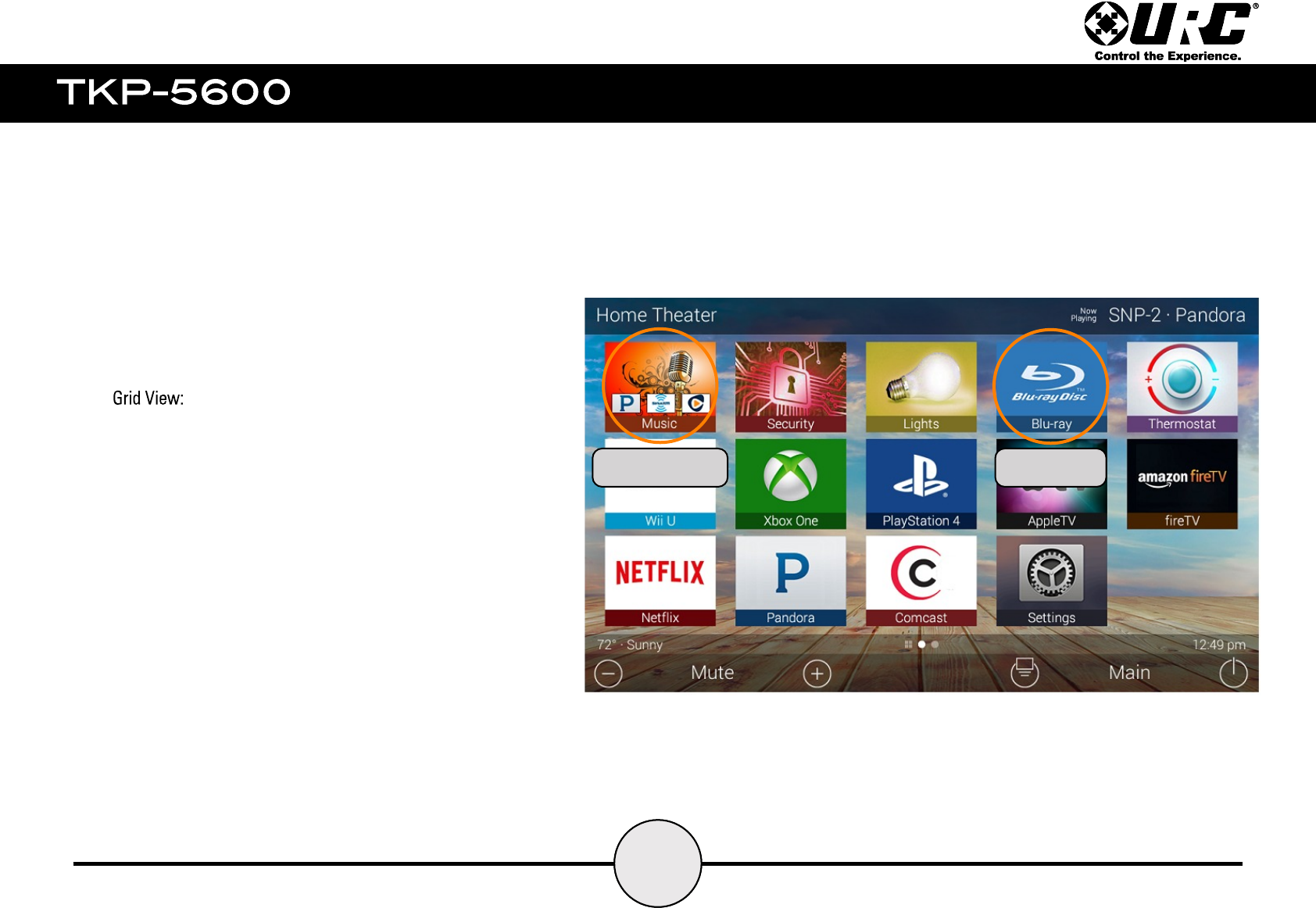
2. This view displays up to fifteen (15) items per page(this
view mode can only be selected from within the URC programming
software) .
All devices that are programmed into the system can be broken
down into categories (Music, Games, Entertainment, etc.). They
can also be left as individual devices.
Selecting one of these categories displays the device menu which
allows for the selection of a particular device and/or activity.
6
Category Device
1
7
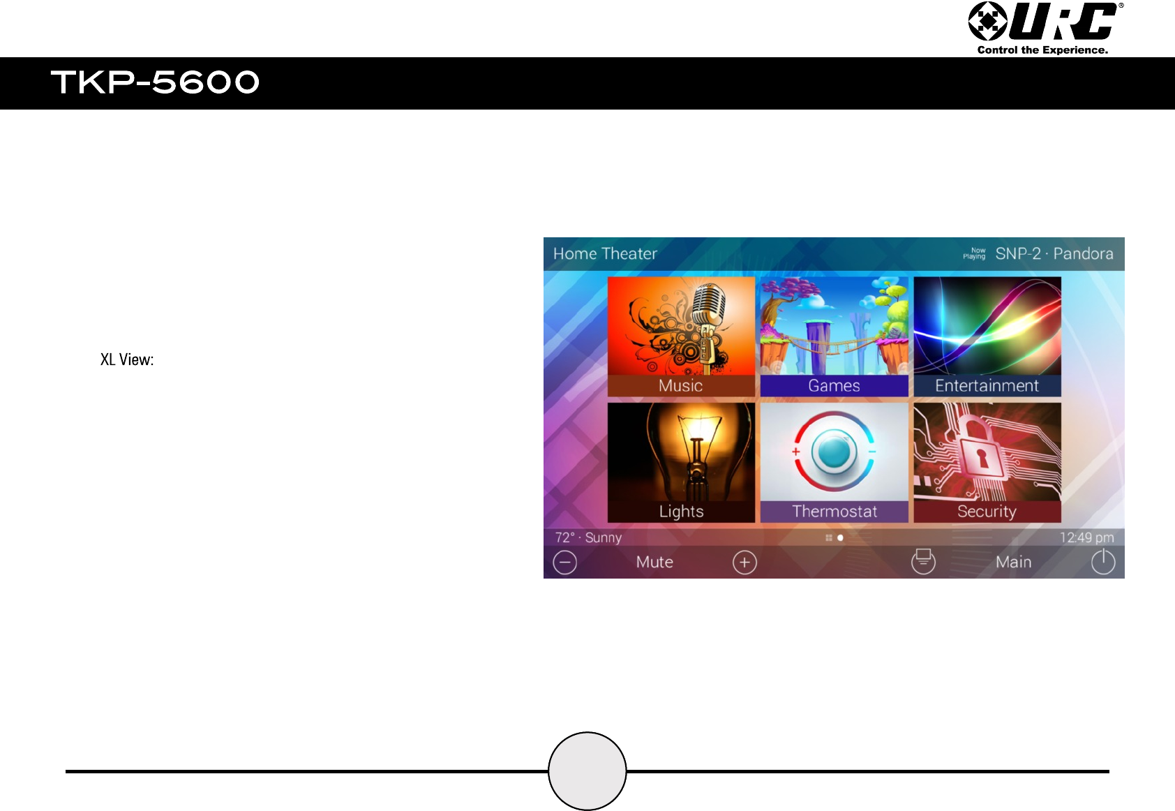
3. this mode allows for extra large icons and only fits a
maximum of six items per page. This view mode can only be
used on touchscreen keypads.
Selecting one of these categories accesses the device menu
which allows for the selection of a particular device or activity.
1
8
1
9
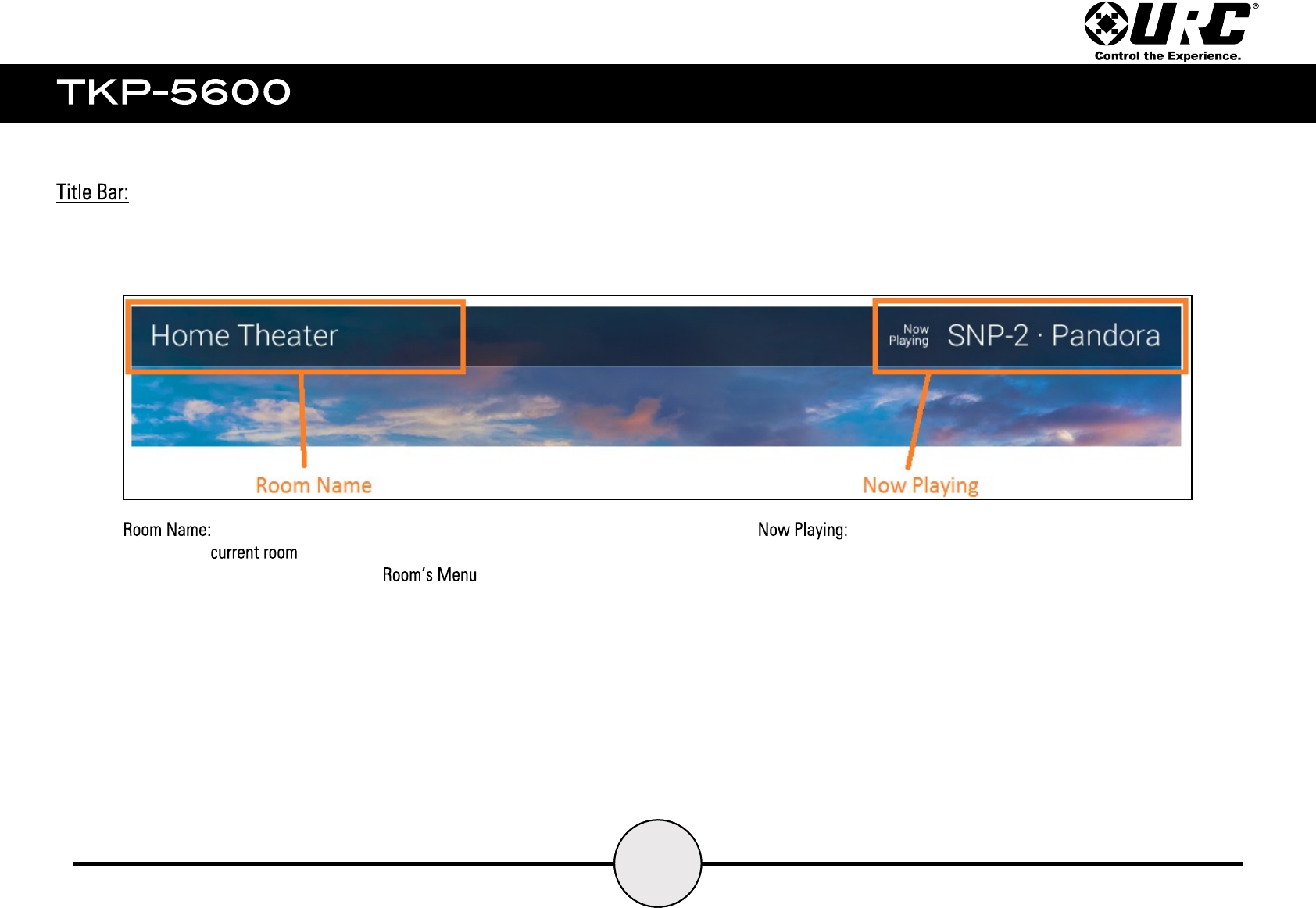
Displays the that the TKP-5600 is controlling.
Selecting the room name displays the
(see Room’s Menu section).
Displays the name of the active source playing in the current room.
If there is no source playing in the room, this area is blank.
Selecting the current room name on the displays the
. This contains a customizable image and room name for each room
programmed into the system.
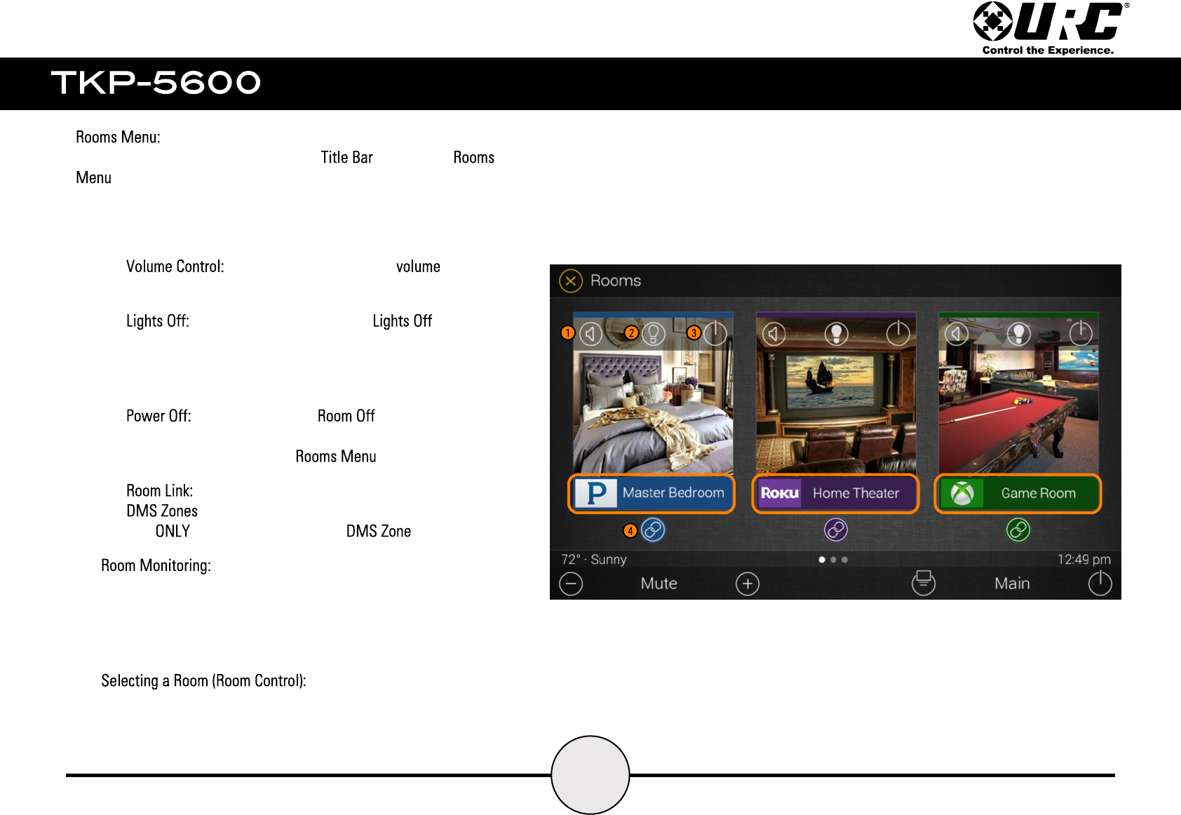
This menu allows for quick control of the following:
1. from this menu, control the for each
individual room in the system.
2. selecting this icon issues the command for
lighting devices programmed to that room. This icon is only
selectable if there are lights programmed into a room and if
those lights are active.
3. this button issues a command that turns off
all the devices programmed into that room. Use this to turn off
rooms individually from the .
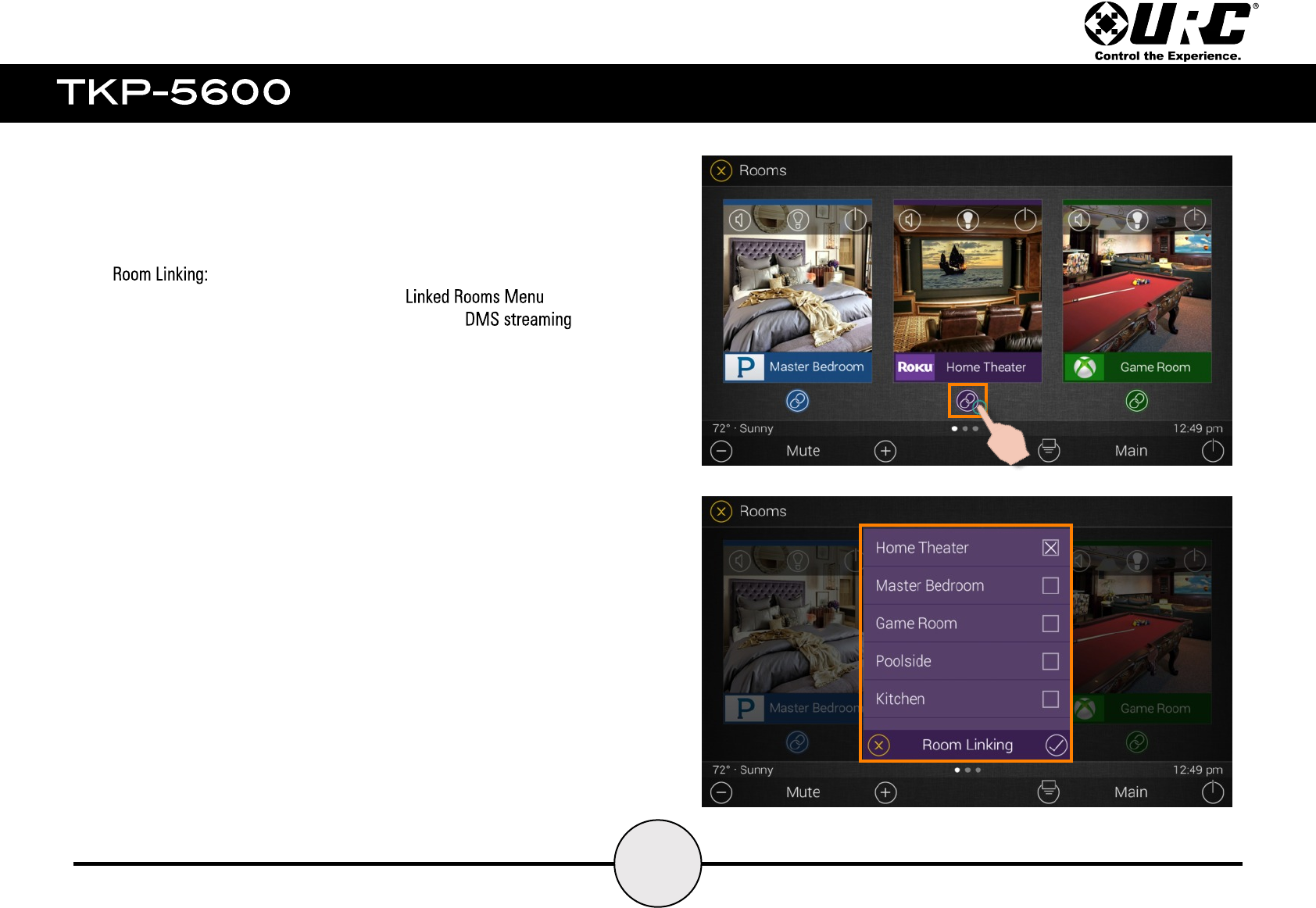
4. selecting this button allows the end-user to select
to link in order to distribute a shared audio source.
This applies to rooms using a .
Each room on this list displays what is currently being used by that
room. For example, the image to the right, the Master Bedroom is
using Pandora, the Home Theater is using a Roku device, and the
Game Room is playing Xbox.
To select a room simply tap the room name or image and the
TKP-5600 displays the interface for that room.
10
11
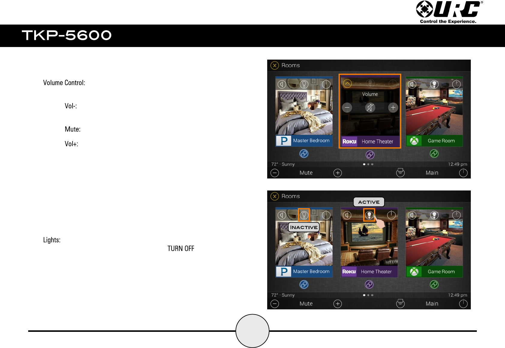
Selecting the Volume button (top left corner of a room) displays the volume menu:
● lowers the volume and pressing & holding it ramps the room
volume down.
● mutes the selected room’s audio.
● raises the volume and pressing & holding it ramps the room
volume up.
Select the Lights icon from the specific room to ALL the
lights in that room.
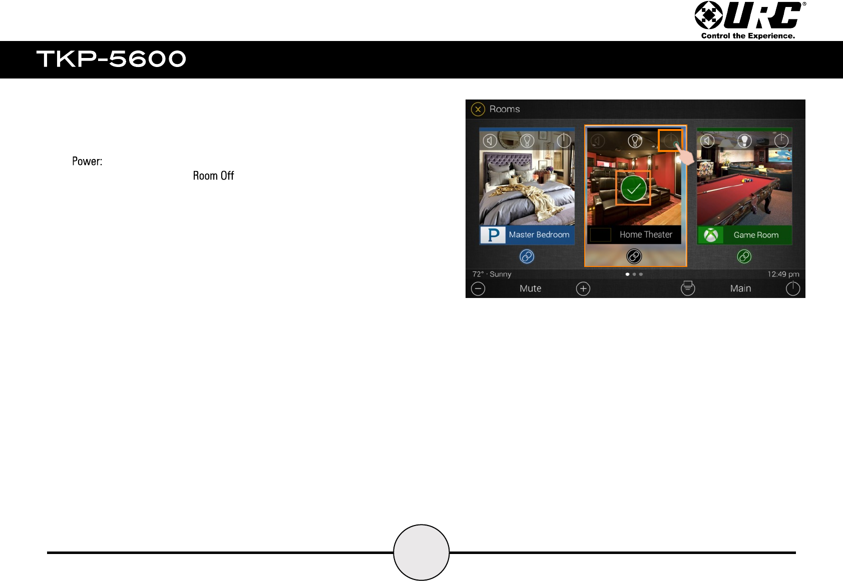
Selecting this icon issues a command turning off all
devices/activities currently running in the Room.
A check mark appears in the center of the Room signifying that the
Room Off command has been executed.
12
13
Selecting the Link Rooms icon displays the . This
settings only applies to rooms that are a part of the
products and only those device appear on this menu (see bottom image).
From this menu select which rooms/zones to link. Select the check box at
the right of the room name to link a Room.
Linking Rooms allows all the rooms selected from this menu to stream a
source over the DMS network. This means that the TKP-5600 can
control the volume of all linked rooms from one easy-to-manage menu.
14
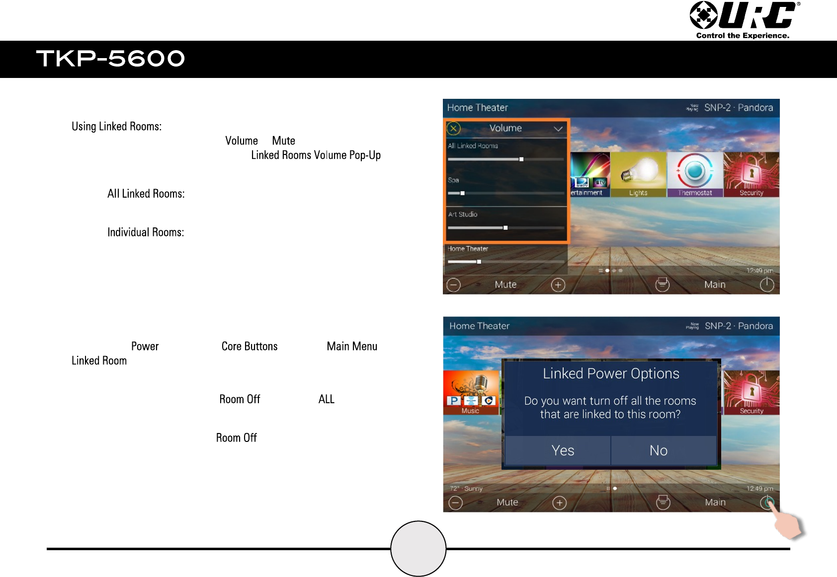
Once a room is linked, pressing the or buttons on the
Main Menu of a linked room displays the
Control functions as such:
● the slider here controls the volume for all
Linked Rooms.
● the Linked Rooms Volume Pop-Up lists all the
linked rooms individually. To control volume for rooms
individually, utilize the slider underneath the room name.
Selecting the button on the within the of
displays this message (see right). This message provides
two (2) options:
●Yes: this options issues a command to
Linked Rooms.
●No: this options issues a command only to the room
currently in use.
All other linked rooms continue to play the streaming audio source.

15
This displays what device or activity is currently being used in
the current room.
Selecting the Now Playing button jumps the TKP-5600 into the
current device or activity.
16
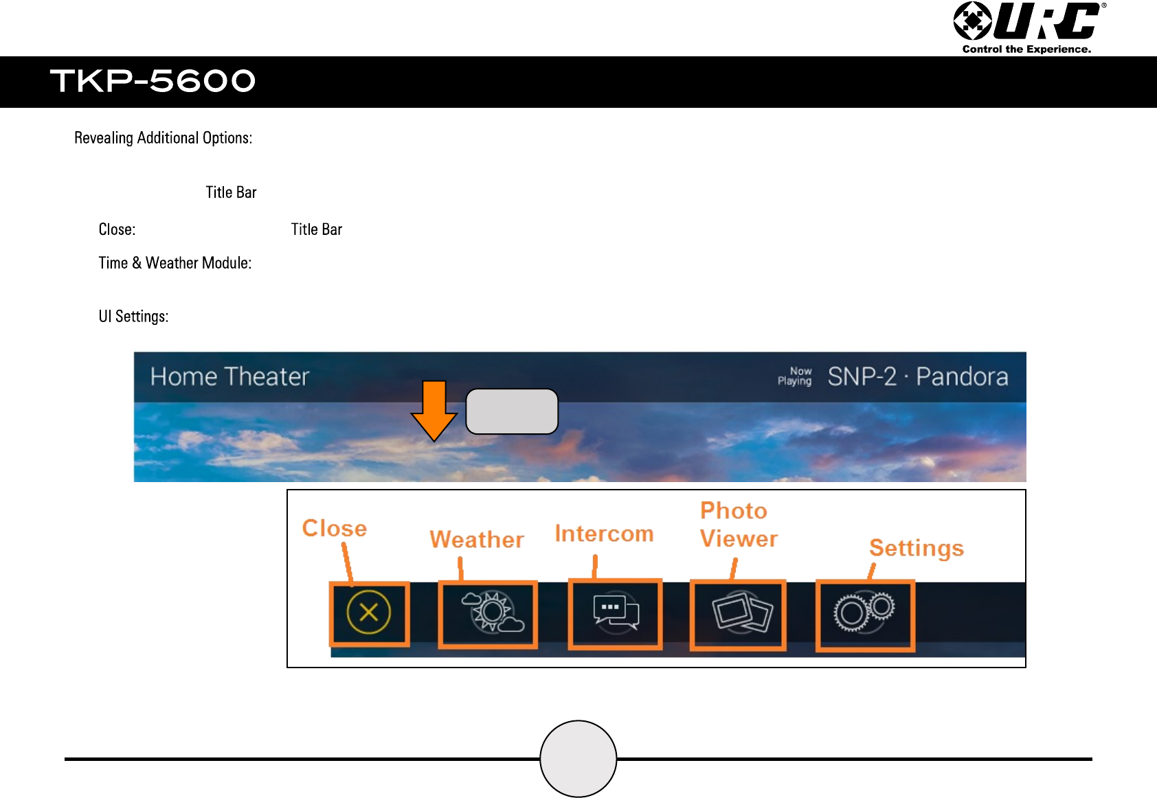
Swipe down from the to reveal the following:
Drag
Down
● selecting this returns the to its default state.
● displays the local time and weather with three (3) day
forecast (set by system programmer).
● displays the Settings Menu for adjustment of internal interface options.
17
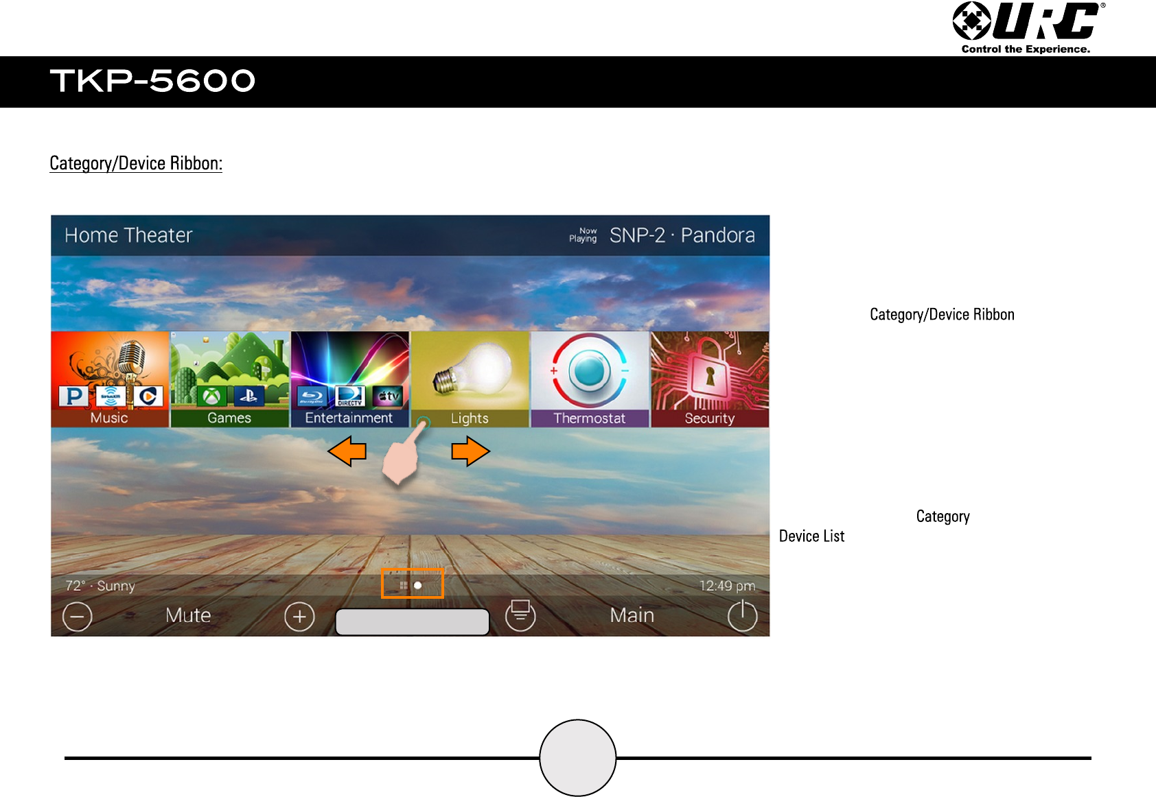
Navigating the is simple. Just
swipe left or right to reveal additional buttons.
By default, Total Control organizes devices/activities
into categories such as:
●Music
●DMS Music
●Entertainment
●Lighting
●Security
●Settings
●Info
●Comfort
Selecting one of these options reveals the
.
Page Indicator
18
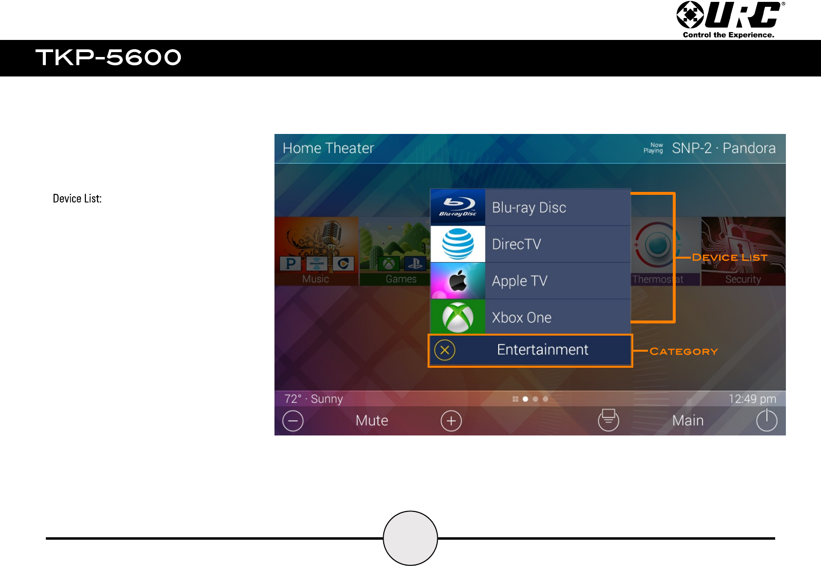
This menu displays the individual devices that
make up the specific category.
The Entertainment category has been selected on
the image to the right.
This displays the available devices (Blu-ray,
DirecTV, Apple TV, etc.) and/or activities
programmed into that category.
Selecting any of these items triggers a series of
commands (macro) that have been programmed by
the system programmer.
19
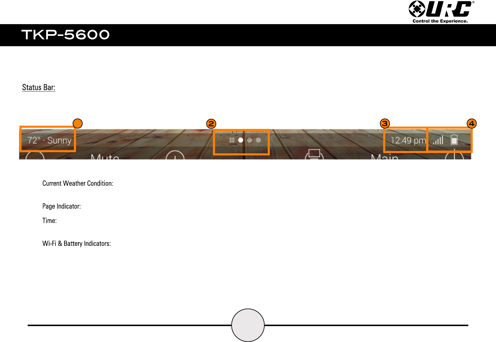
The Status Bar contains the following information:
1
1. displays the current weather information. This information is
updated through the internet and based on the location set by the programmer.
2. displays which page the UI is currently displaying.
3. displays current time. The time mode can be changed from within the TKP-5600’s
Settings Menu.
4. displays the strength of the Wi-Fi signal and the status of
the battery.
20
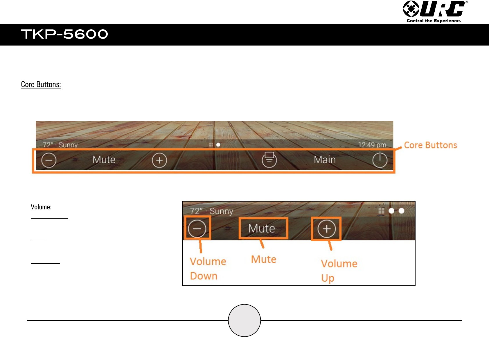
The Core Buttons are static and are ALWAYS displayed regardless what device or menu is present above.
Volume Down: tap this button to lower the room
volume. Holding this button ramps the volume down.
Mute: tap this button to mute the volume in the
current room. Tap again to un-mute the volume.
Volume Up: tap this button to raise the room volume.
Holding this button ramps the volume down.
21
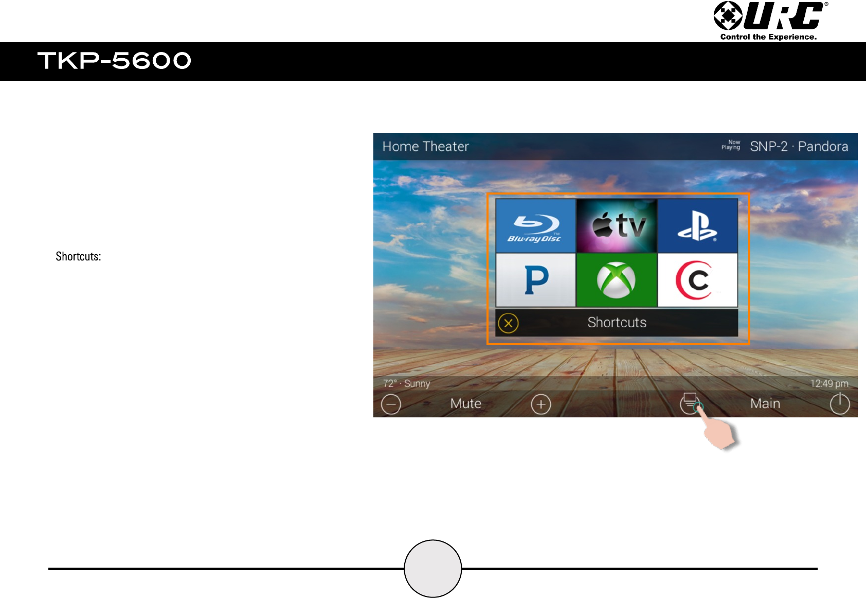
Shortcuts provide easy access to the most commonly used
devices/and or activities of a Total Control system.
Tap the Shortcut icon located to the left of Main. This displays the
Shortcuts Menu. By default this menu is blank and items can be
added here by the programmer or end user.
22
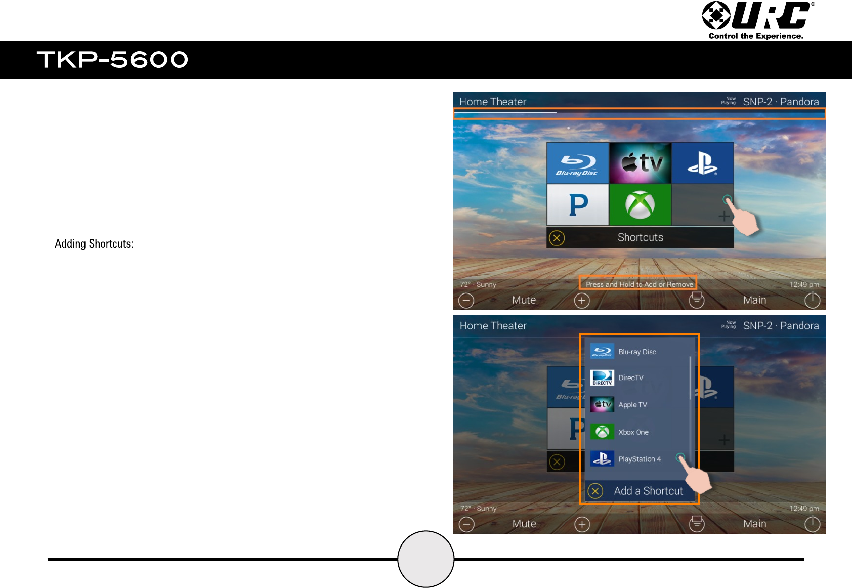
Press and hold on a blank icon until the progress bar located
underneath the Title Bar fills up.
The Add a Shortcuts menu displays devices and activities for the
current room. Choose one item from this list to add it to the
Shortcuts Menu.
There can be a maximum of six (6) Shortcut items added to this
menu. Keep in mind that ONLY devices and/or activities from the
current room can be added.
23
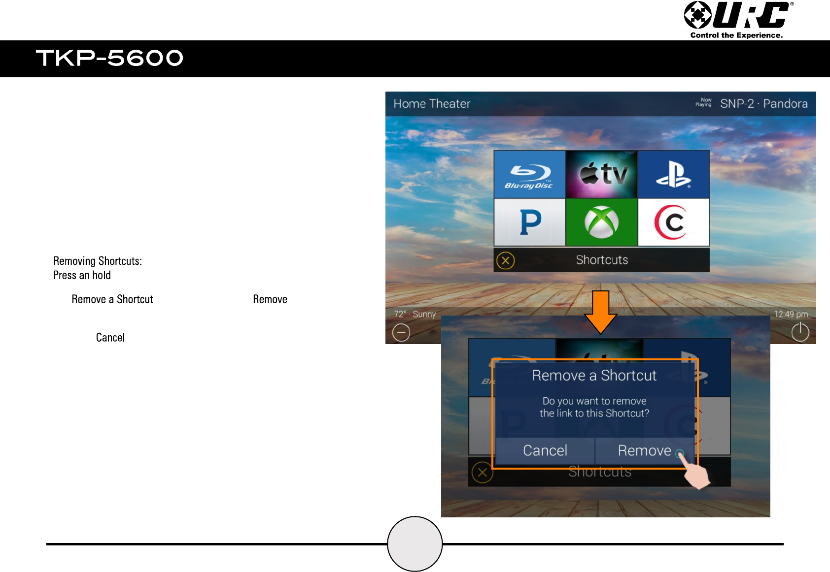
on an icon in order to begin removing it.
The popup displays, select to delete this
item from the Shortcuts Menu.
Selecting returns the UI to the Shortcuts Menu.
24
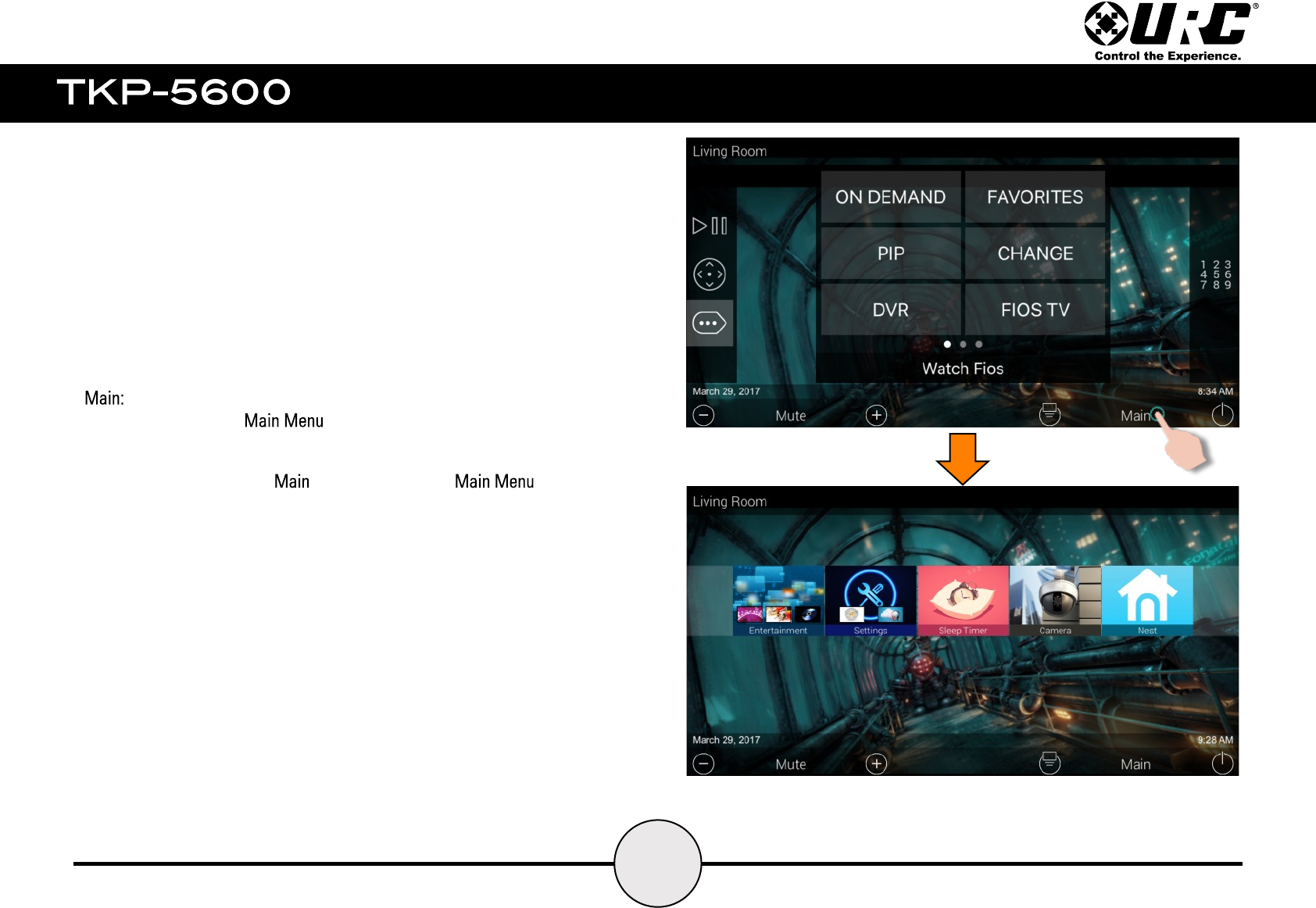
Returns the user to the .
The example at the right (top image) displays the device commands
for the cable box. Selecting returns the UI to the
(bottom image).
25
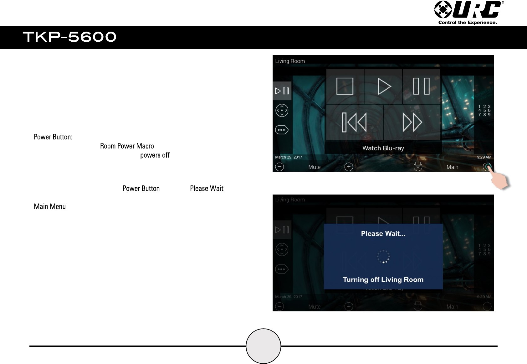
Selecting this triggers a . These macros issue a
series of device power commands that all the devices in the
current room.
The example at the right (top image) displays the transport commands for
the Blu-ray player. Selecting the displays a
screen. After all commands have been issued, the display returns to the
of the current room.
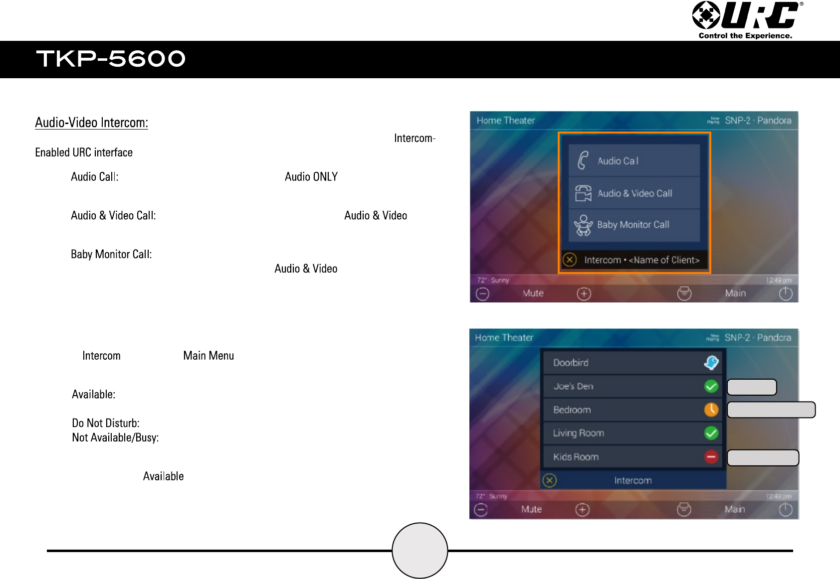
The TKP-5600 has a built-in intercom system that can communicate with any other
. Perform the following using this feature:
● allows the TKP-5600 to communicate over the local network to
any other Intercom-Enabled URC interface.
● allows the TKP-5600 to communicate both over the
local network to any other Intercom-Enabled URC Interface.
● allows the TKP-5600 to utilize the camera and microphone of any other
Intercom-Enabled URC interface. This provides one-way to the
TKP-5600 currently in use.
Select the Icon from the . This displays a list of available devices for
communication. There are three (3) possible states those devices can be in:
● the client (URC interface) is available to receive audio or audio/video
calls.
● the client is set to receive no audio or audio/video calls.
● the client is currently in use and cannot receive audio or
audio/video calls.
To make a call select an client and a menu is displayed of which type of call can
be selected.
Available
Do Not Disturb
Busy/Not Available
26
27
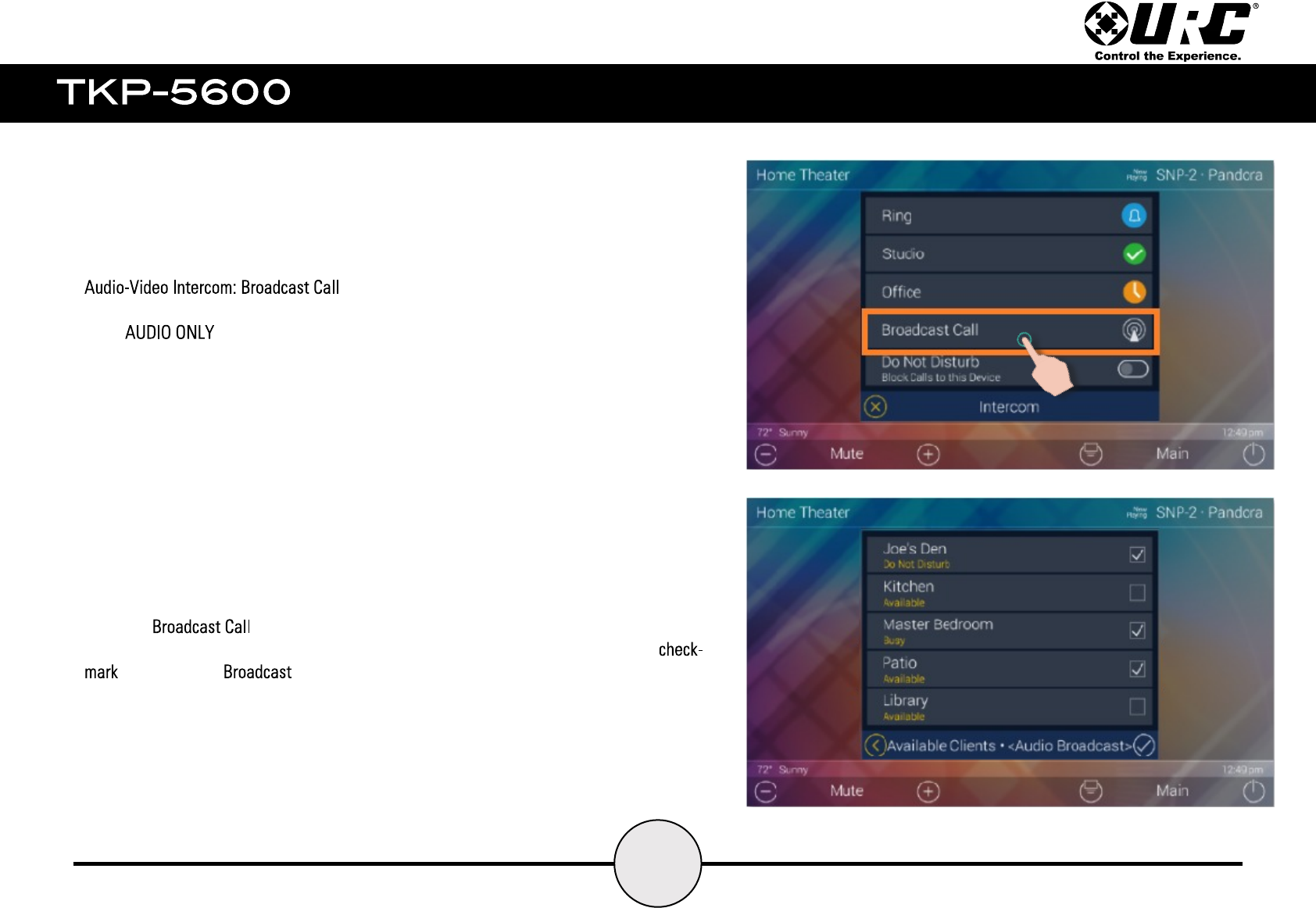
This features allows the TKP-5600 to communicate to multiple Intercom-Enabled UIs at
once. .
Selecting button opens an additional menu that lists all the Intercom-
Enabled UIs. Select which interfaces to be a part of the Broadcast Call, and click the
to execute the .
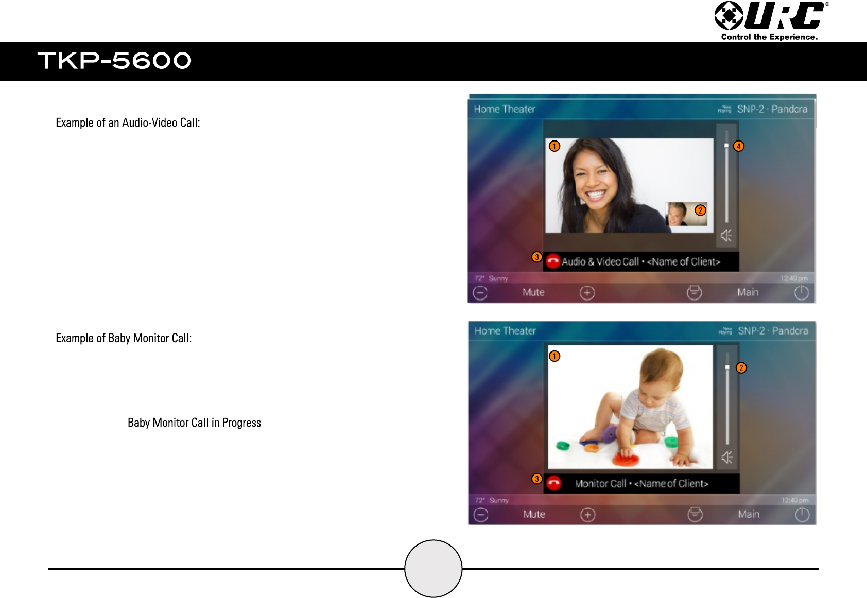
The image to the right displays how an Audio-Video call looks on the
TKP-5600’s screen.
1. Provides the video feed of the receiving client.
2. Provides a thumbnail feed of the calling client.
3. Select this button to end the Audio-Video Call and return to the
Main Menu.
4. Raise & lower volume for Audio call.
The image to the right displays how a Baby Monitor call looks on the
TKP-5600’s screen.
1. Video feed of the receiving client. The receiving client does not
display an image of the calling interface, it presents a window that
states “ ”.
2. Used to control the volume output on the calling device; the
receiving client does not receive any audio or video.
3. Select this button to end the Baby Monitor call and return to the
Main Menu.
28
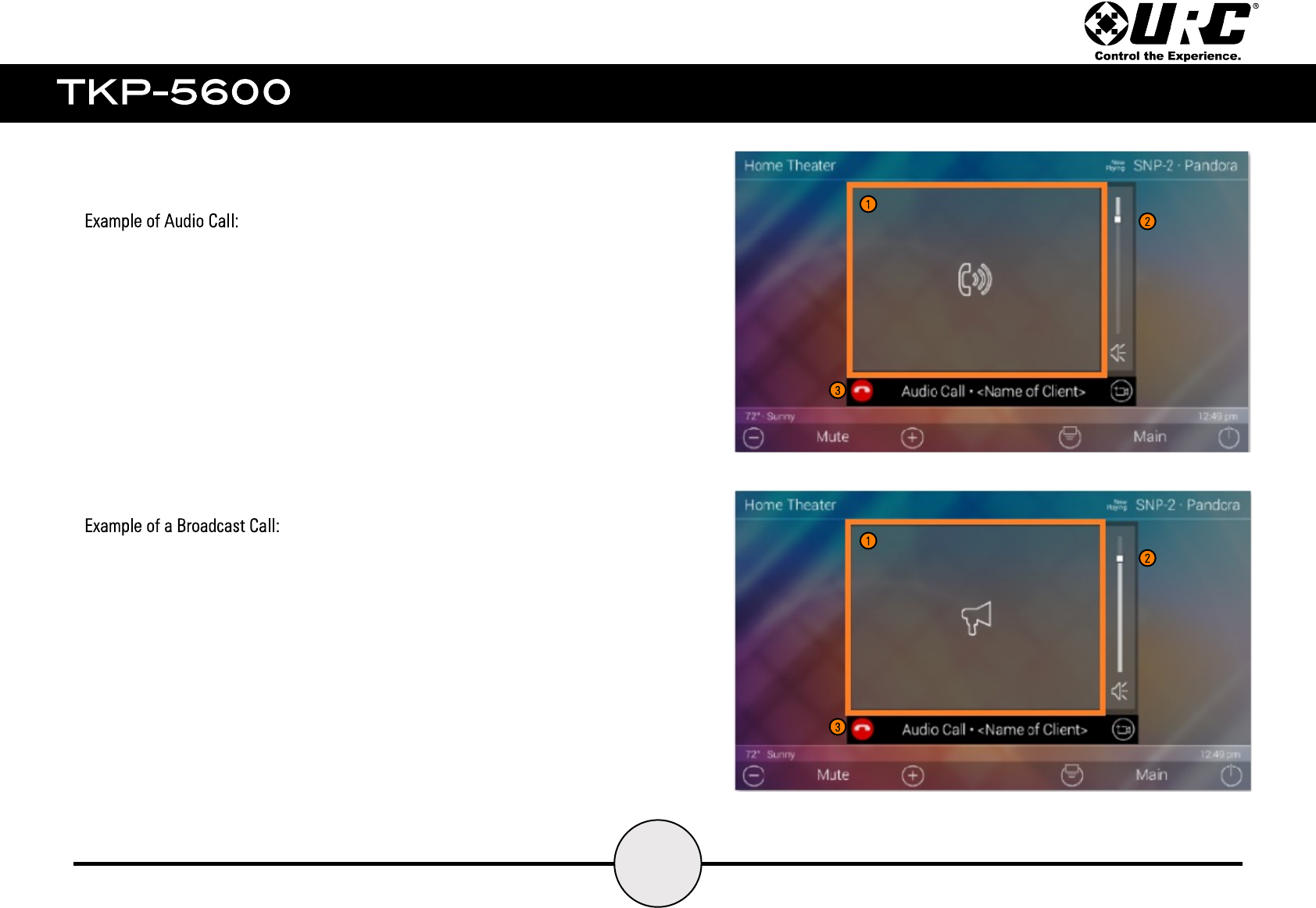
The image to the right displays how an Audio Call looks on the TKP-5600’s screen.
1. This is a static screen and only displays on the TKP-5600 when it is
performing and Audio Call.
2. Used to control the volume output on the calling device.
3. Select this button to end the Audio call and return to the Main Menu.
29
The image to the right displays how a Broadcast call looks on the TKP-5600’s
screen. Remember that a Broadcast Call is an audio only call to two (2) or more
connected clients.
1. This is a static screen and only displays on the TKP-5600 when it is
performing a Broadcast Call. This also displays on each interface involved
in the call.
2. Used to control the volume output on the calling device.
3. Select this button to end the Broadcast Call and return to the Main Menu.
32
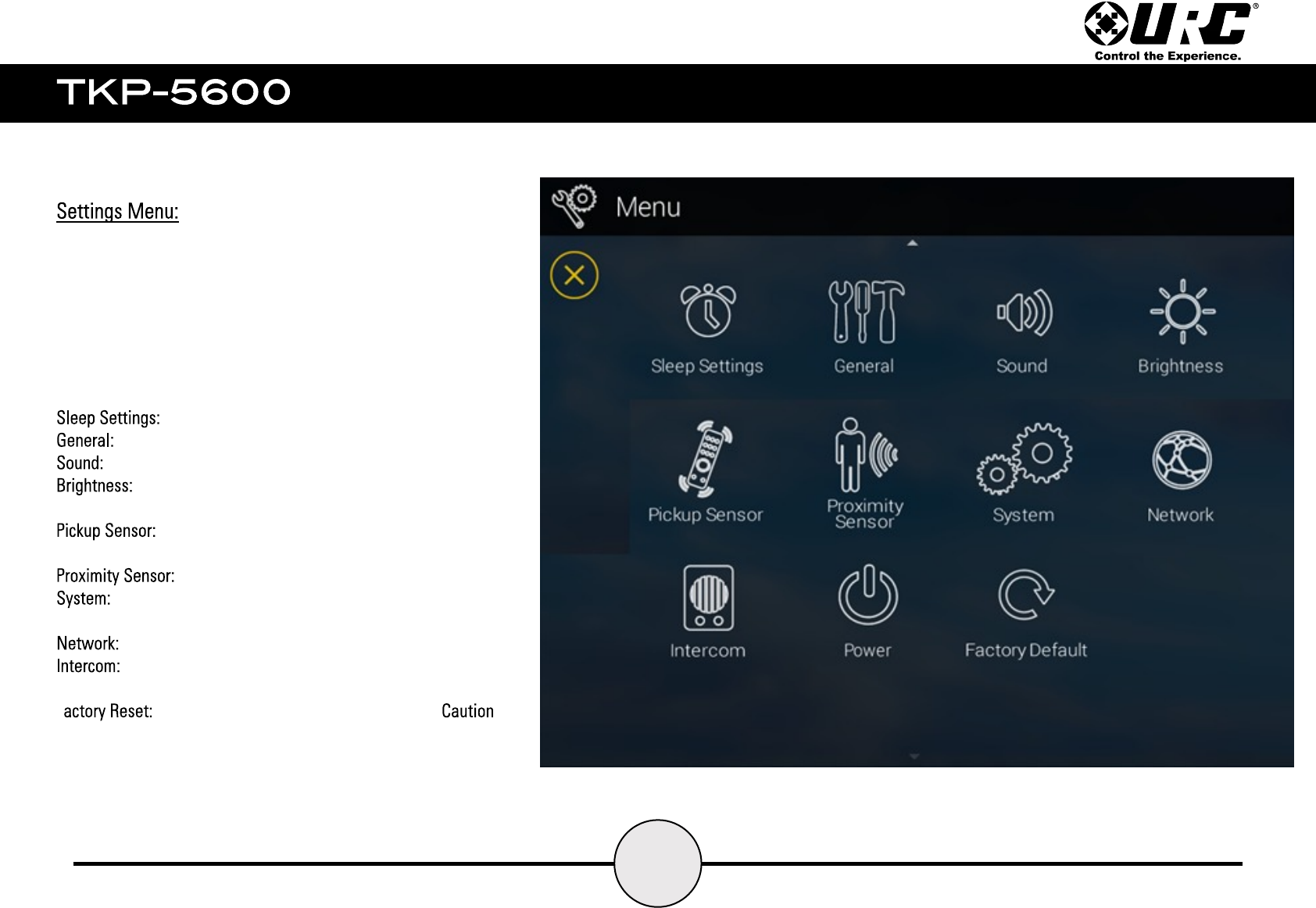
Access the Settings Menu by dragging down the Title Bar and
selecting the Gears icon (see page#).
Most settings do not require interaction with the end-user. Changing
some settings could cause issues with the Total Control system so
only do so when instructed by URC Technical Support.
The Settings Menu consist of the following categories:
manages how long the LCD remains ON after use.
settings for time, date, and temperature scale.
configure audio sounds for calls and notifications.
adjust the LCD’s brightness level and enable/disable the
light sensor.
adjust the sensitivity of the internal sensor that
allows the LCD screen to turn on when picked up.
allows for adjustment of the sensor.
quickly view the memory usage, firmware version and other
details of the device.
Wi-Fi settings and networking properties.
enable/disable audio-video intercom settings to
communicate with other Intercom-Enabled devices.
F rests the TKP-5600 to its factory settings. , do
so requires reprogramming.
33
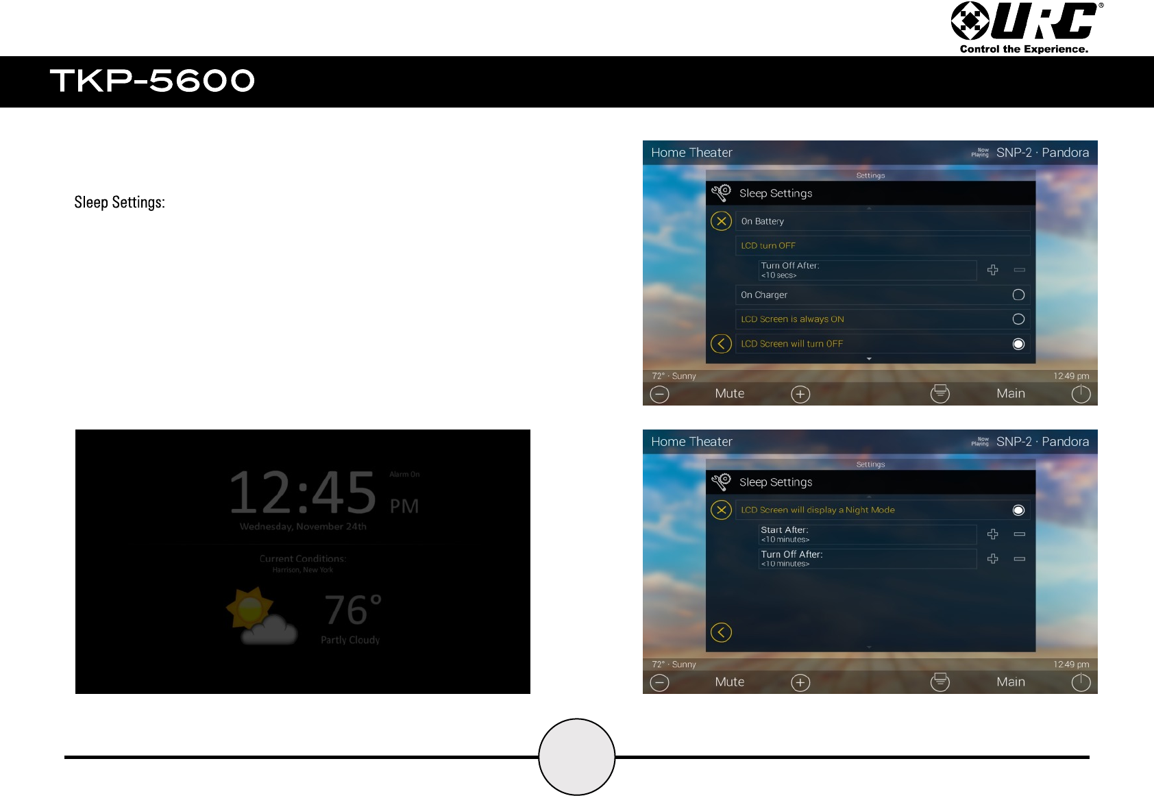
From this menu, decide how long the TKP-5600 should take to
turn off the LCD screen while On Battery.
Also adjust the settings when the TKP-5600 is sitting on its dock
and charging. Choose for the screen to always stay ON, to turn
OFF when placed on the charging dock, or have the LCD display
Night Mode (see below).
34
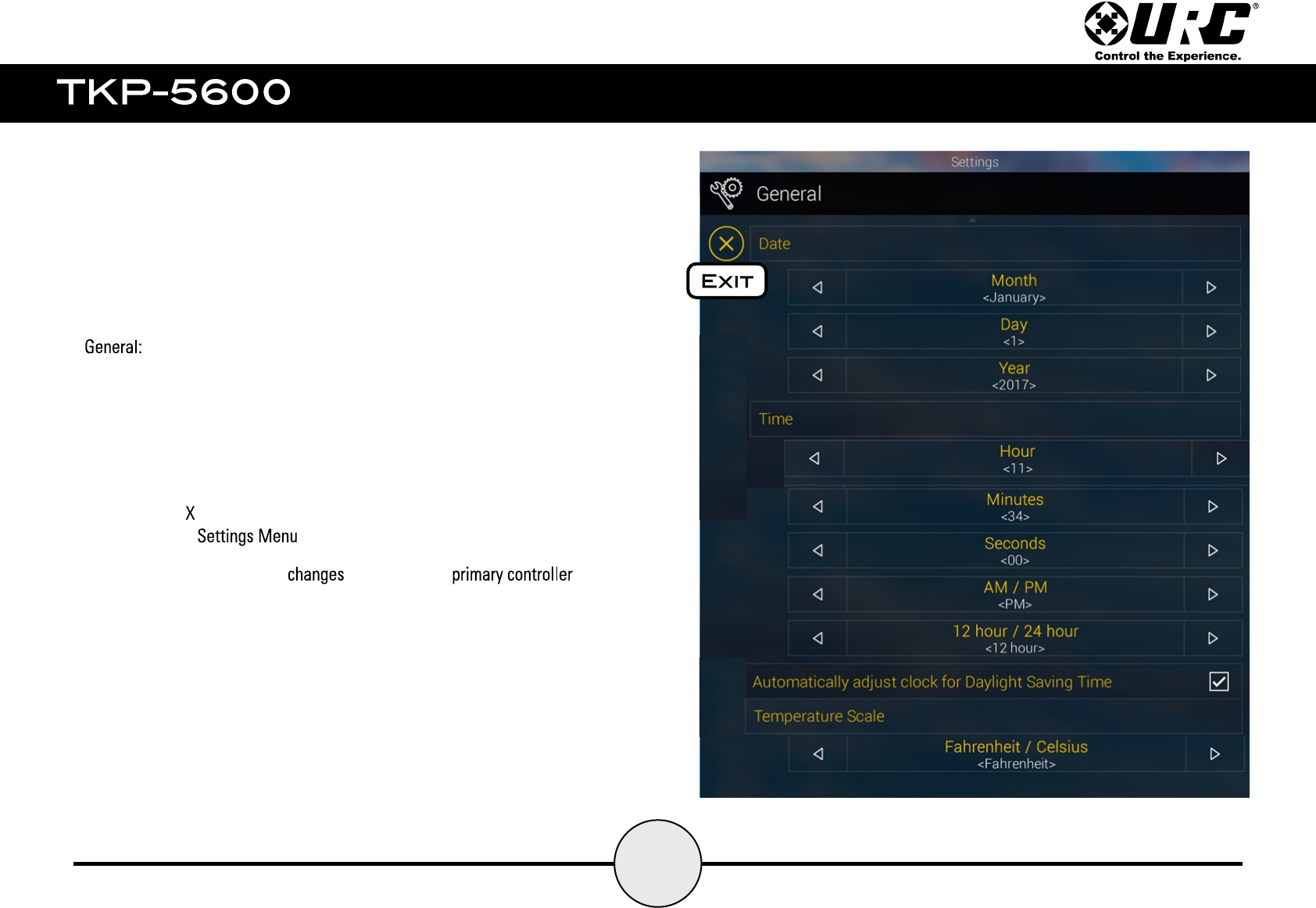
The General settings screen allows the setting of the time, date, and
scale used to display temperature (Fahrenheit/Celsius). To view the rest
of the General settings menu be sure to scroll up or down.
Using the arrows at the left and right sides of each item (hours, minutes,
month, etc.) adjust the value up or down respectively.
Selecting the “ ” located at the top right of this menu returns the
TKP-5600 to the .
Setting the Time & Date here the date in the .
This can be used if system changes time zones.
35
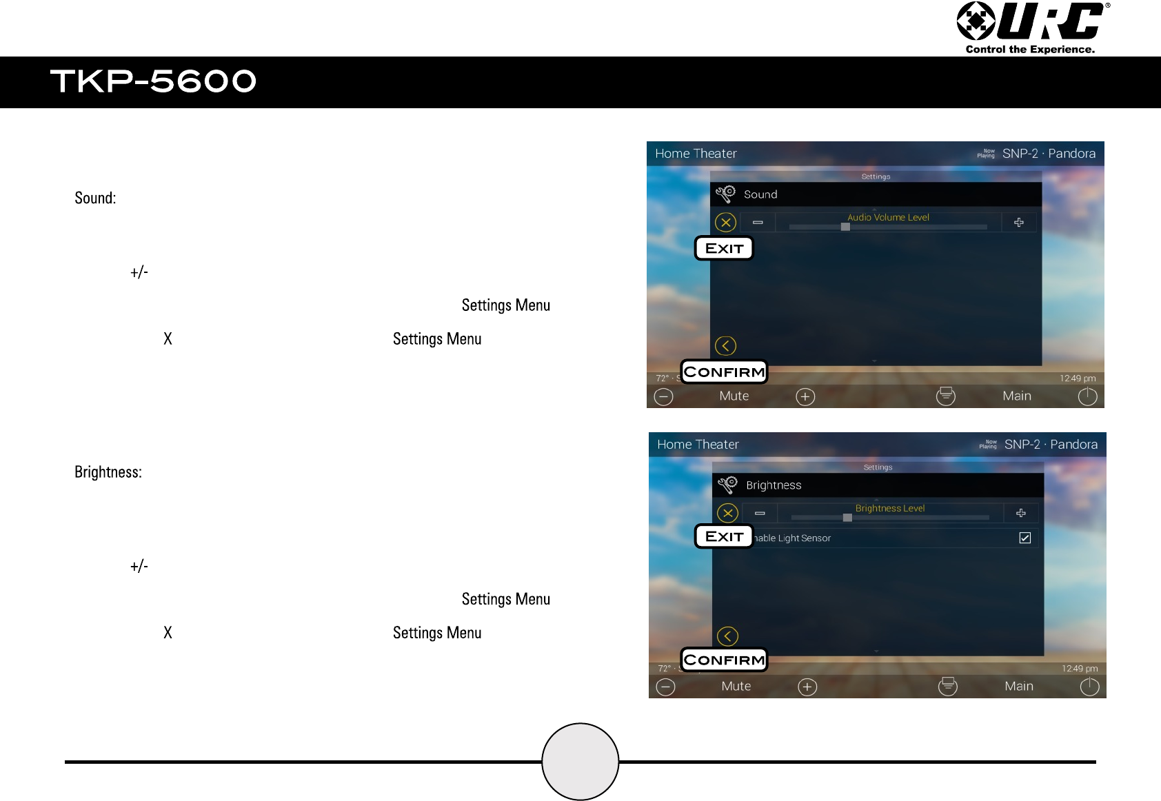
By default, the TKP-5600 emits a low volume beep as a confirmation tone for
screen presses.
Use the “ ” buttons or drag the slider to raise or lower the volume.
Select the check mark to applies the changes and returns to the .
Selecting the “ ” button returns the TKP-5600 to the without
applying any changes.
Determine the overall brightness of the TKP-5600’s display or enable the Light
Sensor. The Light Sensor automatically adjusts the brightness of the device
based upon ambient lighting.
Use the “ ” buttons or drag the slider to raise or lower the volume.
Select the check mark to applies the changes and returns to the .
Selecting the “ ” button returns the TKP-5600 to the without
applying any changes.

36
This menu allows for adjustment on the sensitivity of the pickup sensor.
Choose from low, medium, or high sensitivity settings.
Use the “ ” buttons or drag the slider to raise or lower the volume.
Select the check mark to applies the changes and returns to the .
Selecting the “ ” button returns the TKP-5600 to the without
applying any changes.
This menu allows for the adjustment on the distance on the proximity sensor.
The distances from lowest to highest are: 10cm, 25cm, 50cm, 75cm, and 100cm.
Use the “ ” buttons or drag the slider to raise or lower the volume.
Select the check mark to applies the changes and returns to the .
Selecting the “ ” button returns the TKP-5600 to the without
applying any changes.
37
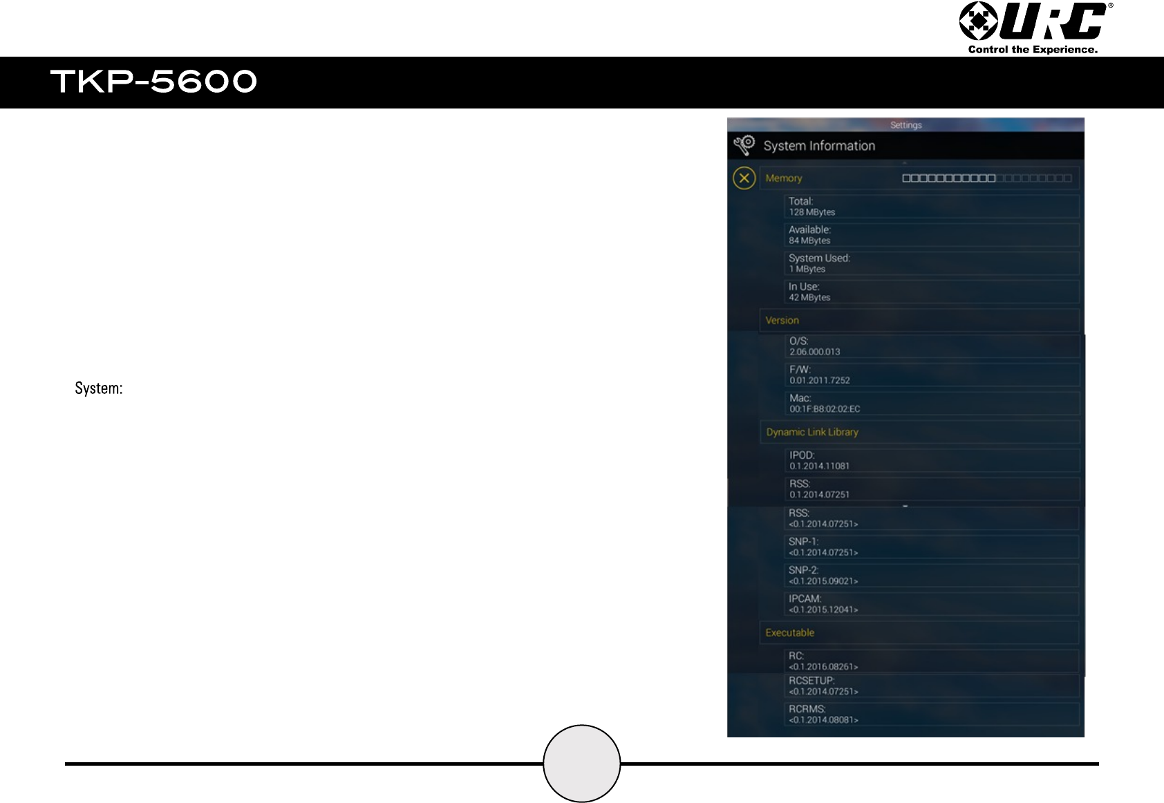
Although non of the information can be modified, these System pages show important
information about the TKP-5600. These pages should only be needed by a custom install
professional or URC technical support.
40
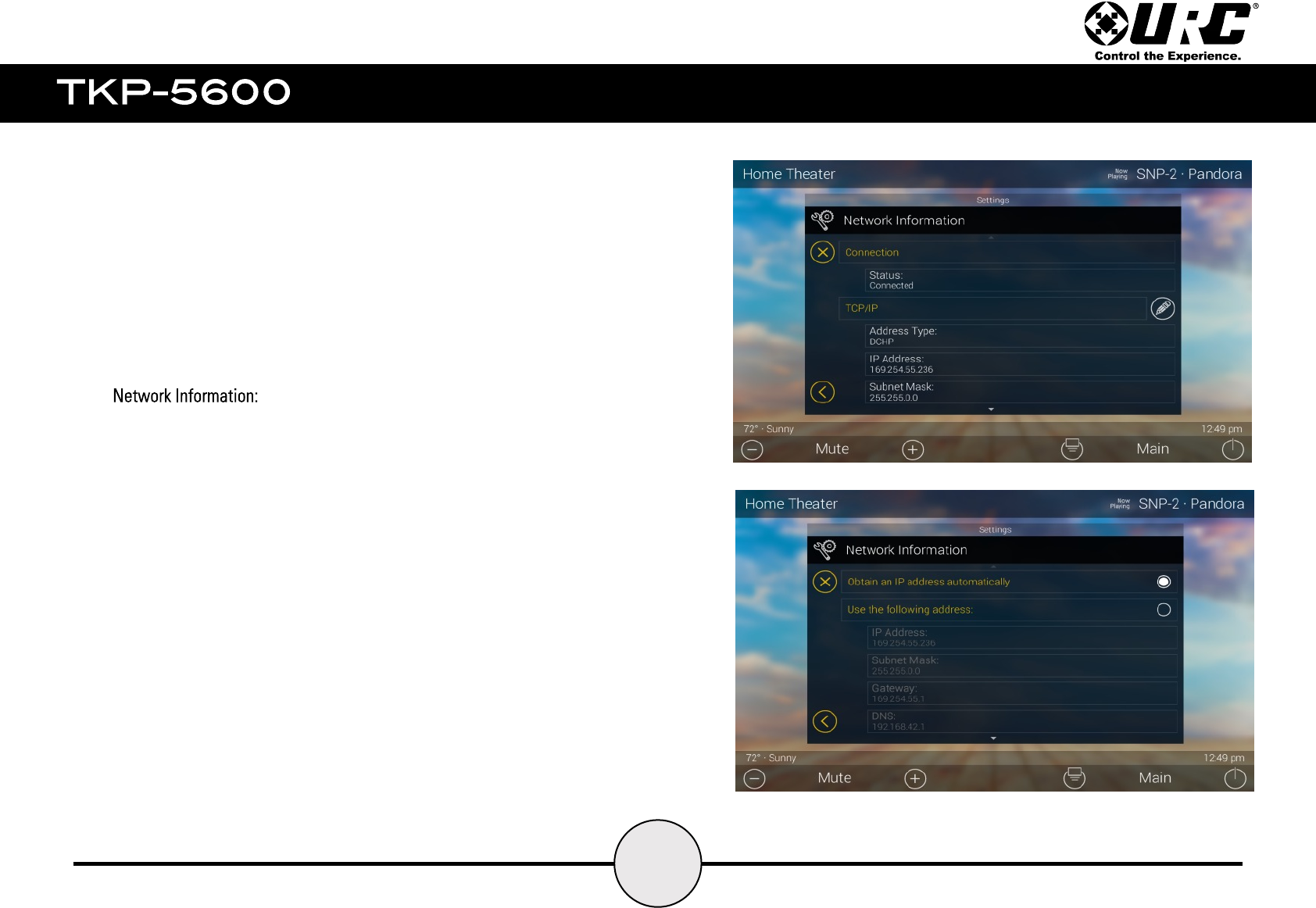
This screen provides network information about the current network
Wi- Fi connection. Information displayed here includes but is not limited
to, Connection Status, Address Type, IP Address, Subnet Mask, etc.
These settings are setup by the programmer at initial installation of the
system and do not require modifications unless directed by URC’s
Technical Support or the system programmer.
41
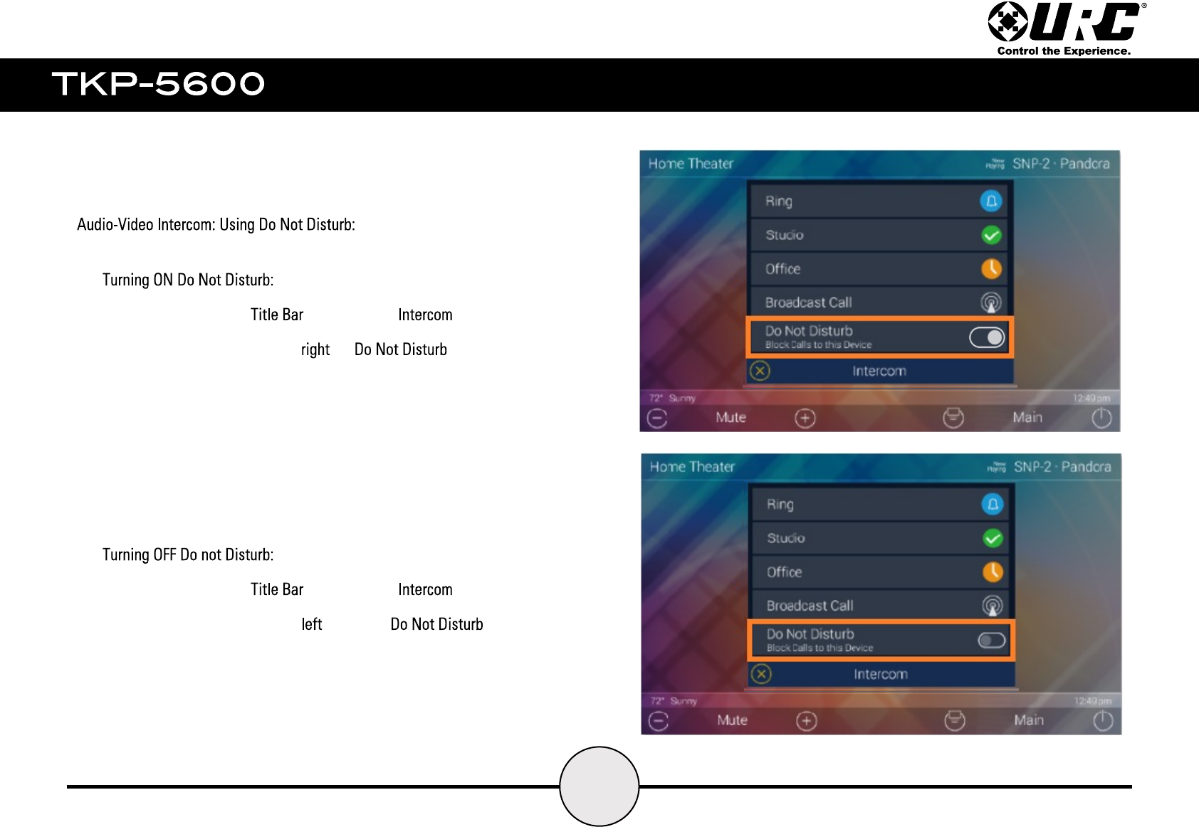
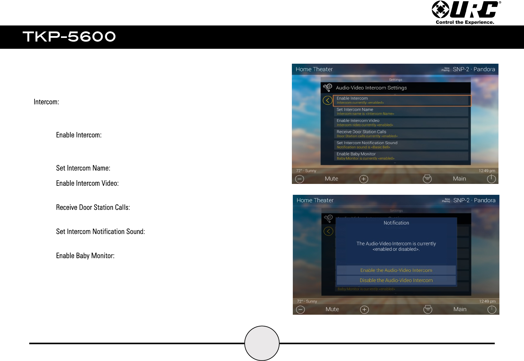
In order to use the TKP-5600’s Intercom feature, it must first be Enabled from
within the Settings Menu. Perform the following this menu:
● select this option to enable the Intercom for the
TKP-5600, if this is left disable the device CANNOT make or receive
any Intercom calls (see image at bottom right).
● enter a name for the device’s Intercom.
● this enables the TKP-5600 to make and
receive video on Audio-Video calls.
● enabling this allows the TKP-5600 to
receive calls from 3rd party Door Stations like DoorBird.
● select a notification tone for
Intercom calls.
●enabling this allows the TKP-5600 to make
Baby Monitor calls, remember this is a one-way call where the
receiving device does have audio or video on the calling unit.
42
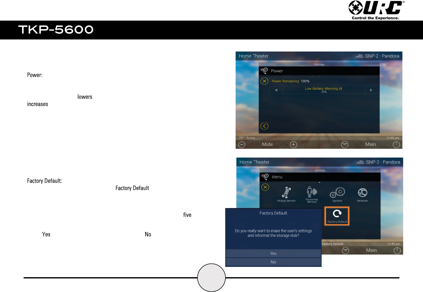
Use this setting to view the current Power level on the battery of the TKP-5600.
Also use this to adjust when the device should remind the user of charging the
device. The left button the percentage value while the right button
that numeral.
The value set here allows the TKP-5600 to send a battery warning when that
percentage of power has been reached.
Warning, this resets the TKP-5600 to its state. This means that
all custom programming is erased.
Only do this under the instruction of URC’s Technical Support or by the system
programmer. Press and hold the Factory Default button for greater than (5)
seconds. This displays confirmation window.
Select to complete the factory reset process. The button returns to the
Settings Menu.
43
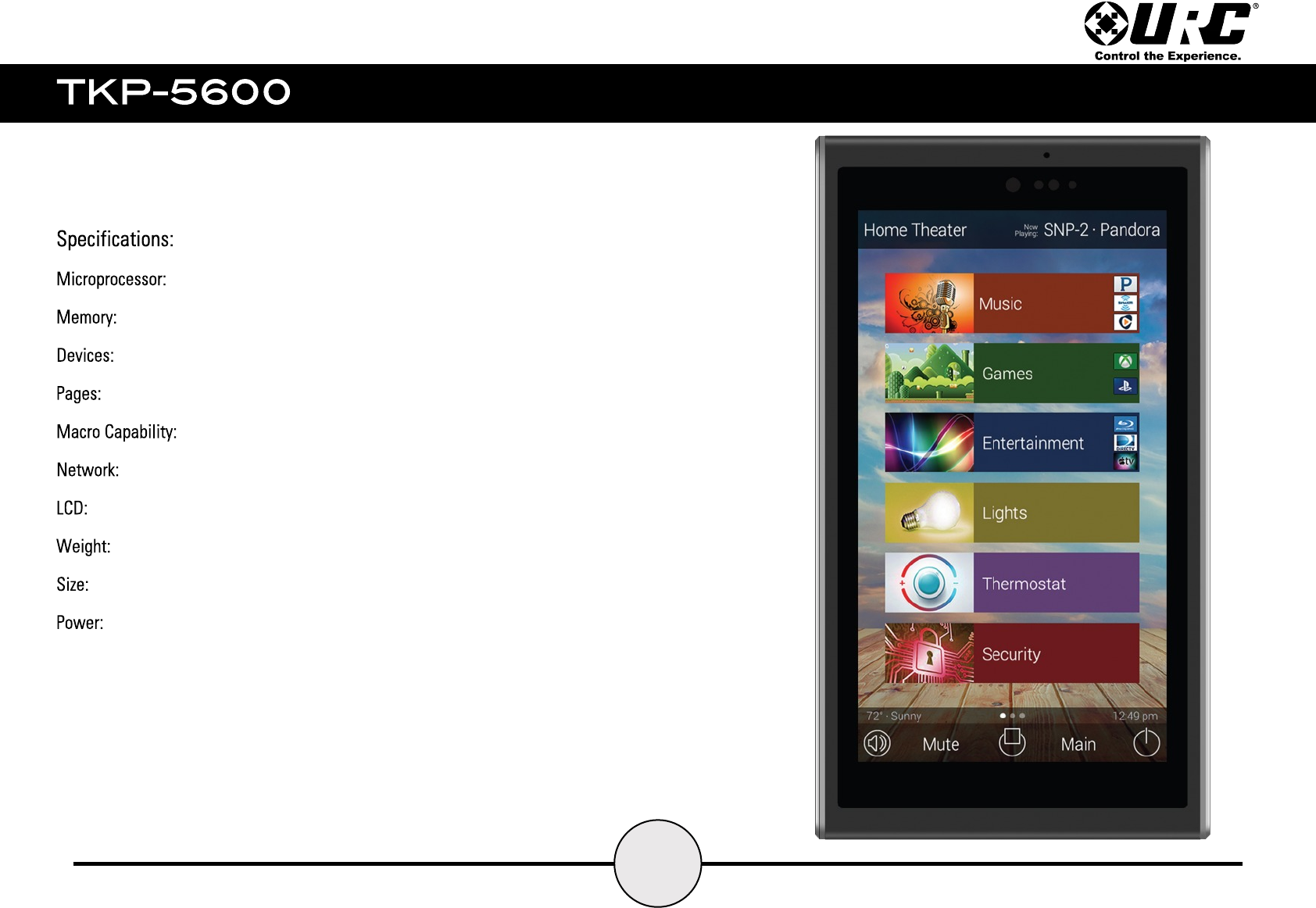
Coretex-A9 dual 1GHz
4GB eMMC, 1GB RAM
Supports up to 255 Devices
Supports up to 255 Pages on each Device
Up to 255 steps
One 10/100 Ethernet port (PoE)
5 inch (960x540)
6.28 oz
3.15"(L) x 5.62"(H) x 0.96"(D)
Standard PoE Injector or PoE Switch (Purchased separately)

44
Limited Warranty Statement
1. Limited Warranty and Disclaimers
Universal Remote Control, Inc. (“URC”) warrants that the URC equipment shall be free from defects in material and workmanship under normal
usage for one (1) year from purchase when such is purchased from URC. This limited warranty is valid only in the United States of
America. URC warrants that the software will substantially conform in any material respect to its functional specifications at the time of
delivery. URC SHALL NOT BE LIABLE FOR OPERATIONAL, TECHNICAL OR EDITORIAL ERRORS AND/OR OMISSIONS MADE IN THE URC
DOCUMENTATION. URC DOES NOT WARRANT THAT THE URC SOFTWARE IS BUG-FREE OR ERROR FREE OR THAT THERE ARE NO
ERRORS/BUGS IN THE URC SOFTWARE.
URC warrants that at the time of purchase the URC equipment and the URC software complied with all applicable regulations and policies of
the Federal Communications Commissions (“FCC”) regarding electromagnetic interference caused by electronic/computing devices and to the
extent that the URC equipment and/or the URC software fails to so comply, URC shall, at its own expense, take all reasonable measures to
promptly cause such to comply.
URC equipment purchases from other than an authorized URC dealer or distributor are without warranty.
THIS LIMITED WARRANTY DOES NOT COVER TECHNICAL ASSISTANCE FOR HARDWARE OR SOFTWARE USAGE EXCEPT AS EXPRESSLY
PROVIDED FOR HEREIN, THE EQUIPMENT, SOFTWARE AND DOCUMENTATION OF URC ARE SUPPLIED “AS IS” WITHOUT ANY WARRANTY,
EXPRESS, STATUTORY OR IMPLIED, OF ANY KIND. TO THE MAXIMUM EXTENT PERMITTED BY APPLICABLE LAW, URC EXPRESSLY DISCLAIMS
ALL WARRANTIES, EXPRESS, STATUTORY OR IMPLIED, INCLUDING BUT NOT LIMITED TO THE WARRANTIES OF MERCHANTABILITY AND
FITNESS FOR A PARTICULAR PURPOSE. URC DOES NOT WARRANT, GUARANTEE, OR MAKE ANY REPRESENTATIONS REGARDING THE USE
OF, OR THE RESULTS OF THE USE OF, THE EQUIPMENT, SOFTWARE OR DOCUMENTATION IN TERMS OF CORRECTNESS, ACCURACY,
RELIABILITY OR OTHERWISE. EXCEPT AS EXPRESSLY PROVIDED FOR HEREIN, TECHNICAL SERVICES ARE SUPPLIED “AS IS”, WITHOUT ANY
WARRANTY, EXPRESS, STATUTORY OR IMPLIED, OF ANY KIND. TO THE MAXIMUM EXTENT PERMITTED BY APPLICABLE LAW, URC EXPRESSLY
DISCLAIMS ALL.
WARRANTIES, EXPRESS, STATUTORY OR IMPLIED, INCLUDING BUT NOT LIMITED TO THE WARRANTIES OF QUALITY OR
REASONABLE SKILL AND CARE, OR OUTCOME OR RESULTS.

45
WITHOUT IN ANY WAY LIMITING THE GENERALITY OF THE OTHER PROVISIONS HEREIN, WARRANTY DOES NOT COVER: (I) DAMAGE
FROM MISUSE, NEGLECT OR ACTS OR NATURE, (II) MODIFICATIONS, (III) INTEGRATION WITH THIRD PARTY CONTENT (IV) BEYOND THE
WARRANTY PERIOD AND/ OR FAILURE TO FOLLOW URC WARRANTY CLAIM PROCEDURE.
The warranty limitations and warranty disclaimers may not apply to end user in whole or in part, where such are restricted or excluded by
applicable law and such shall apply to the maximum extent permitted by applicable law.
In the event of any warranty claim, URC will, at its sole option, repair the URC equipment using new or comparable rebuilt parts, or exchange
the URC equipment for new or rebuilt equipment. In the event of a defect, these are the end user’s exclusive remedies.
All the URC equipment returned for service, exchange or repair require an RGA number. To obtain an RGA number, you must complete a
Return Request Form which you may obtain by calling (914) 835- 4484 or contacting URC at returnrequest@universalremote.com. To
obtain warranty service, end user must deliver the URC equipment, freight prepaid, in its original packaging or packaging affording adequate
protection to URC at 420 Columbus Avenue, Valhalla, NY 10595. It is end user’s responsibility to backup any macro programming, artwork,
software or other materials that may have been programmed into the unit. It is likely that such data, software, or other materials will be lost
during service and URC will not be responsible for any such damage or loss. A dated purchase receipt, bill of sale, installation contract or
other verifiable proof of purchase is required. For the URC equipment support and other important information, please visit URC's website
available at www.universalremote.com or call the Customer Service Center at (914) 835-4484.
This limited warranty only covers the URC equipment issues caused by defects in material or workmanship during ordinary consumer use. It
does not cover product issues caused by any other reason, including but not limited to product issues due to commercial use, acts of God,
third-party installation, misuse, limitations of technology, or modification of or to any part of the URC equipment. This limited warranty does
not cover the URC equipment sold as used, as is, refurbished, so called "B stock" or consumables (such as batteries). This limited warranty is
invalid if the factory applied serial number has been altered or removed from the URC equipment. This limited warranty specifically excludes
the URC equipment sold by unauthorized resellers.
With the exception of URC’s IR-only, broad-based consumer remotes, none of Page 36 URC’s PC programmable remotes or any of our Total
Control® whole-house equipment are authorized for online Internet sales. Buying URC’s PC programmable remotes or any of our Total

46
Control® whole- house equipment online means buying equipment that does not have a URC’s limited warranty. Such equipment is not
eligible for URC tech support or software support, either.
2. URC’s Limitations of Liability
IN NO EVENT SHALL URC BE LIABLE FOR INDIRECT, SPECIAL, INCIDENTAL, EXEMPLARY, PUNITIVE OR CONSEQUENTIAL DAMAGES OF ANY
KIND OR LOSS OF PROFITS OR BUSINESS OPPORTUNITY, EVEN IF URC IS ADVISED OF THE POSSIBILITY OF SUCH DAMAGES.
IN NO EVENT SHALL URC BE LIABLE FOR LOSS OF OR DAMAGE TO DATA, COMPUTER SYSTEMS OR COMPUTER PROGRAMS. URC’S
LIABILITY, IF ANY, FOR DIRECT DAMAGES OF ANY FORM SHALL BE LIMITED TO ACTUAL DAMAGES, NOT IN EXCESS OF AMOUNTS PAID BY
END USER FOR THE URC EQUIPMENT.
IN NO EVENT SHALL URC BE LIABLE FOR ANY EVENTS BEYOND ITS CONTROL, INCLUDING ANY INSTANCE OF FORCE MAJEURE. IN NO
EVENT SHALL URC BE LIABLE FOR THE ACTS OR OMISSIONS OF END USER OR ANY THIRD PARTY.
THE LIMITATIONS OF LIABILITY MAY NOT APPLY TO END USER IN WHOLE OR IN PART, WHERE SUCH ARE RESTRICTED LIMITED OR
EXCLUDED BY APPLICABLE LAW AND SUCH SHALL APPLY TO THE MAXIMUM EXTENT PERMITTED BY APPLICABLE LAW.
URC SHALL NOT BE HELD RESPONSIBLE FOR THE STATEMENTS MADE BY OTHERS.
SOME STATES OR JURISDICTIONS DO NOT ALLOW THE EXCLUSION OR LIMITATION OF INCIDENTAL OR CONSEQUENTIAL DAMAGES, OR
ALLOW LIMITATIONS ON HOW LONG AN IMPLIED WARRANTY LASTS, SO THE ABOVE LIMITATIONS OR EXCLUSIONS MAY NOT APPLY TO
END USER. THIS LIMITED WARRANTY GIVES END USER SPECIFIC LEGAL RIGHTS AND END USER MAY HAVE OTHER RIGHTS WHICH VARY
FROM STATE TO STATE OR JURISDICTION TO JURISDICTION.
47
End User Agreement
The terms and conditions of the End User Agreement available at www.universalremote.com/eua.php
Federal Communications Commission Interference Statement
This equipment has been tested and found to comply with the limits for a Class B digital device, pursuant to part 15 of the FCC Rules. These limits
are designed to provide reasonable protection against harmful interference in a residential installation. This equipment generates, uses and can
radiate radio frequency energy and, if not installed and used in accordance with the instructions, may cause harmful interference to radio
communications. However, there is no guarantee that interference will not occur in a particular installation. If this equipment does cause harmful
interference to radio or television reception, which can be determined by turning the equipment off and on, the user is encouraged to try to
correct the interference by one more of the following measures:
●Reorient or relocate the receiving antenna.
●Increase the separation between the equipment and receiver.
●Connect the equipment into an outlet on a circuit different from that to which the receiver is connected.
●Consult the dealer or an experienced radio/TV technician for help.
Warning!
Changes or modifications not expressly approved by the manufacturer could void the user's authority to operate the equipment.
Note : The manufacturer is not responsible for any Radio or TV interference caused by unauthorized modifications to this equipment. Such
modifications could void the user's authority to operate the equipment.
FCC Caution
This device complies with Part 15 of the FCC Rules. Operation is subject to the following two conditions: (1) this device may not cause harmful
interference, and (2) this device must accept any interference received, including interference that may cause undesired operation.