Olympus Medical Systems RU2020 Endoscope Reprocessor User Manual GT9882 0100 fm10
Olympus Medical Systems Corp. Endoscope Reprocessor GT9882 0100 fm10
UserManual.wiki
>
Olympus Medical Systems
>
RU2020 User Manual
>
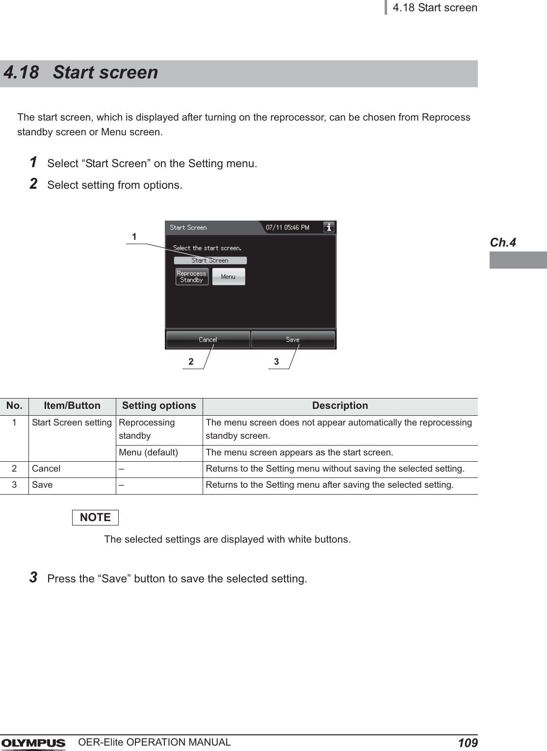
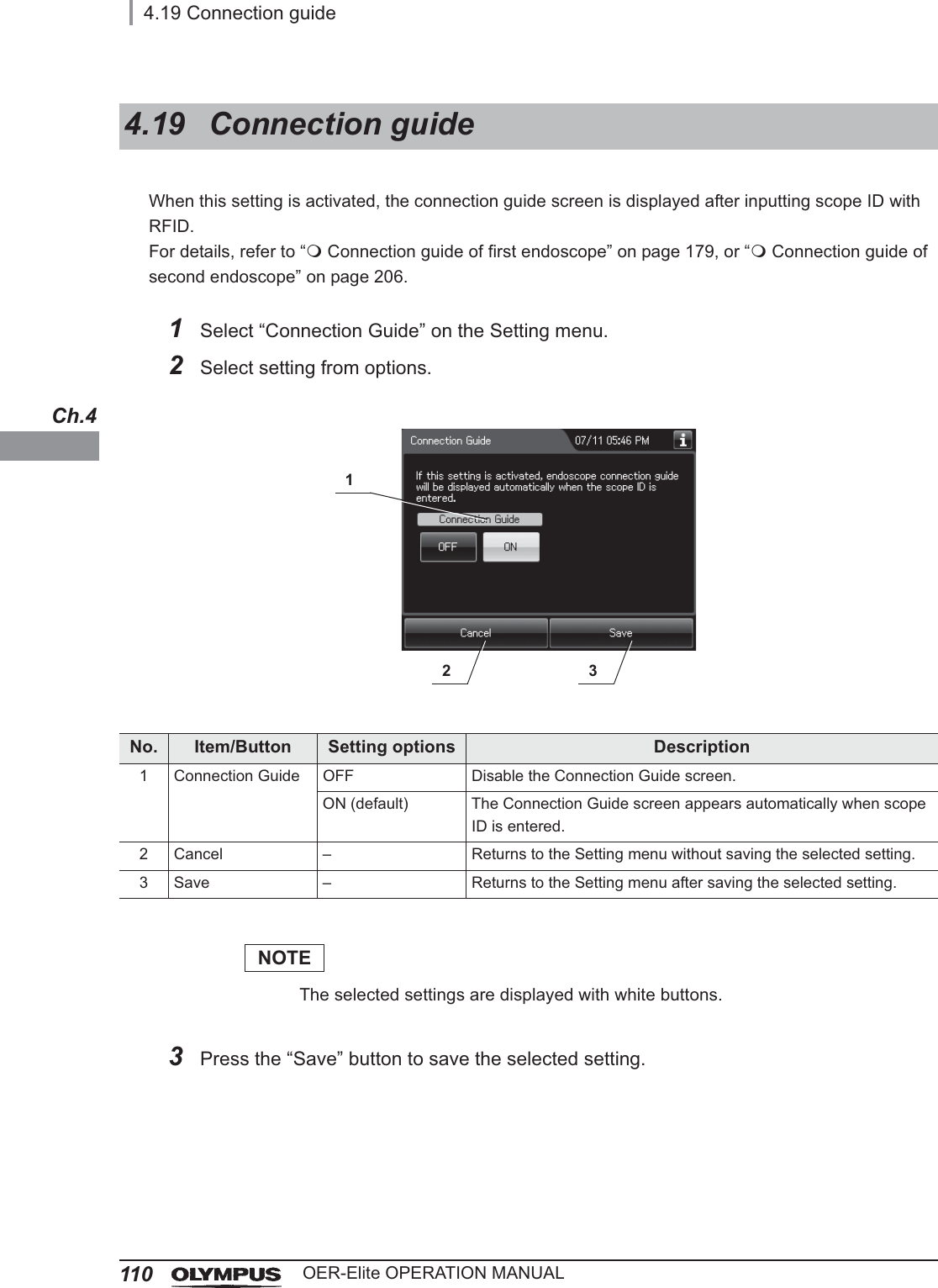
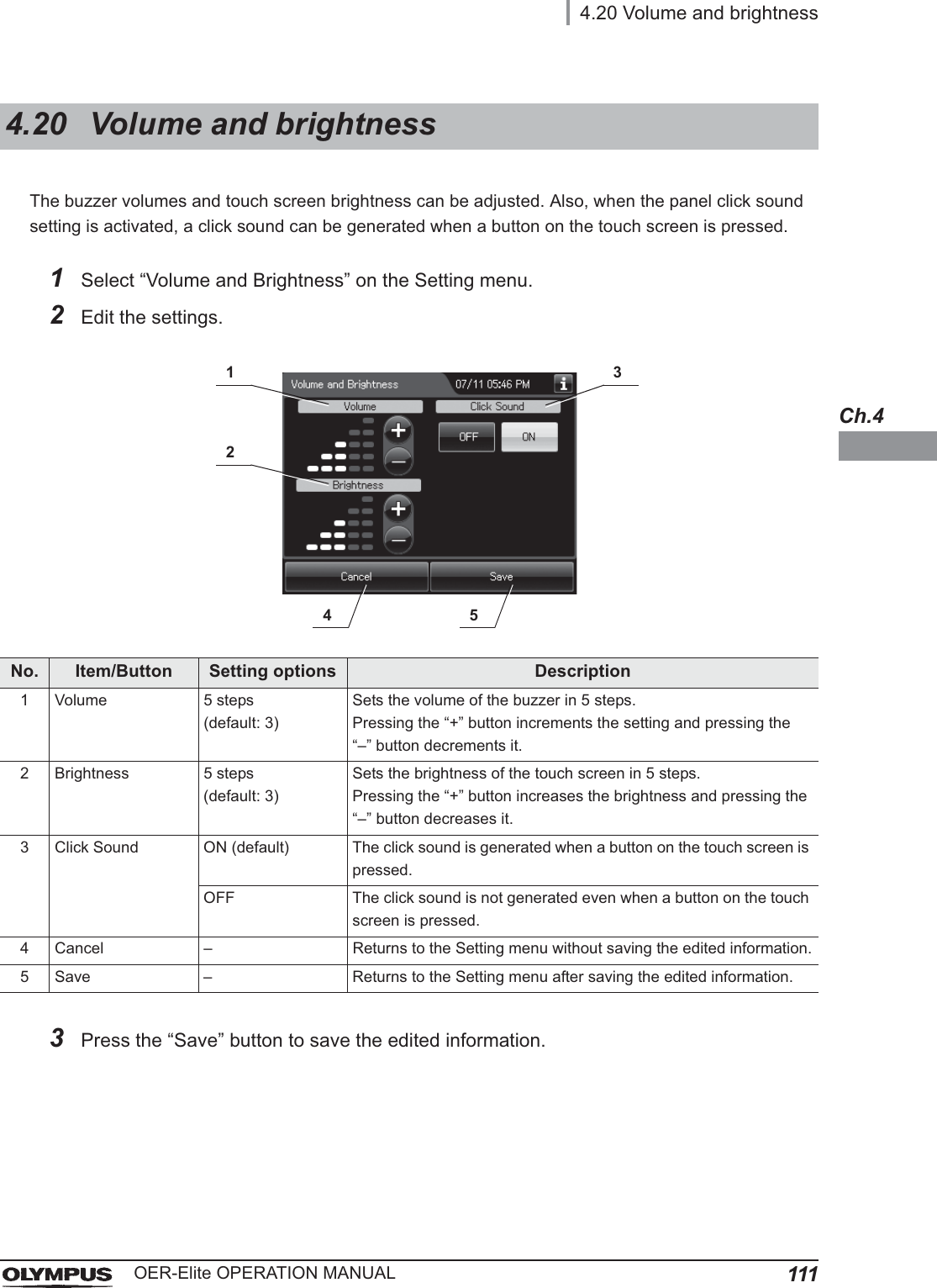
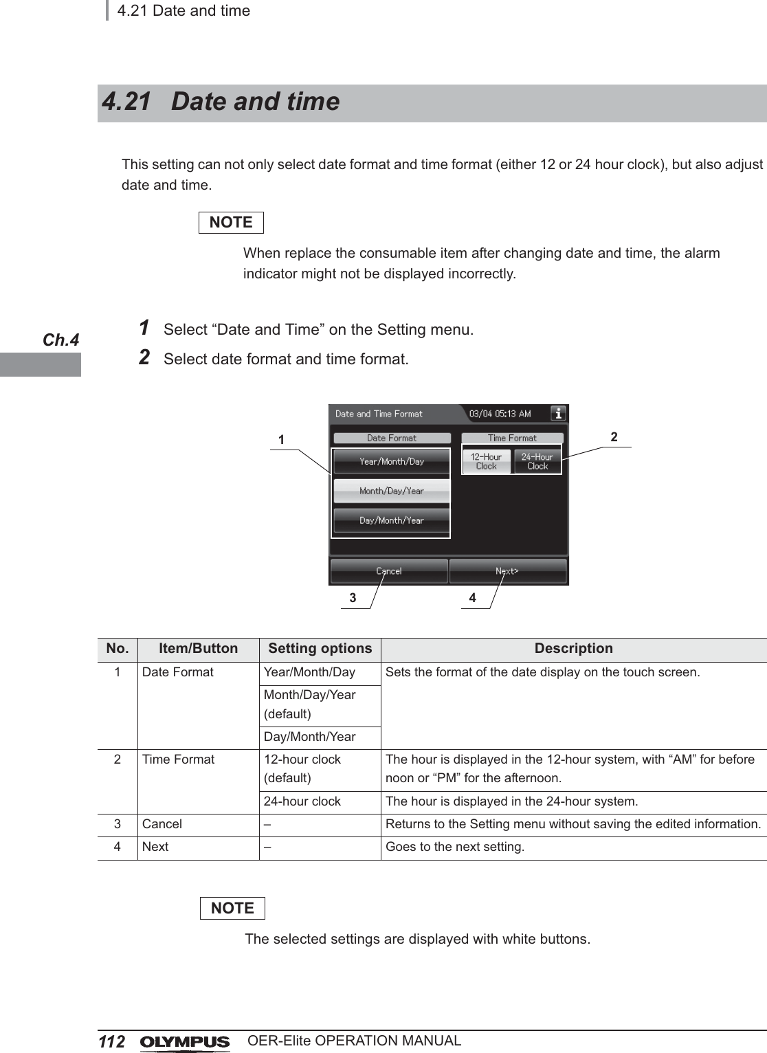
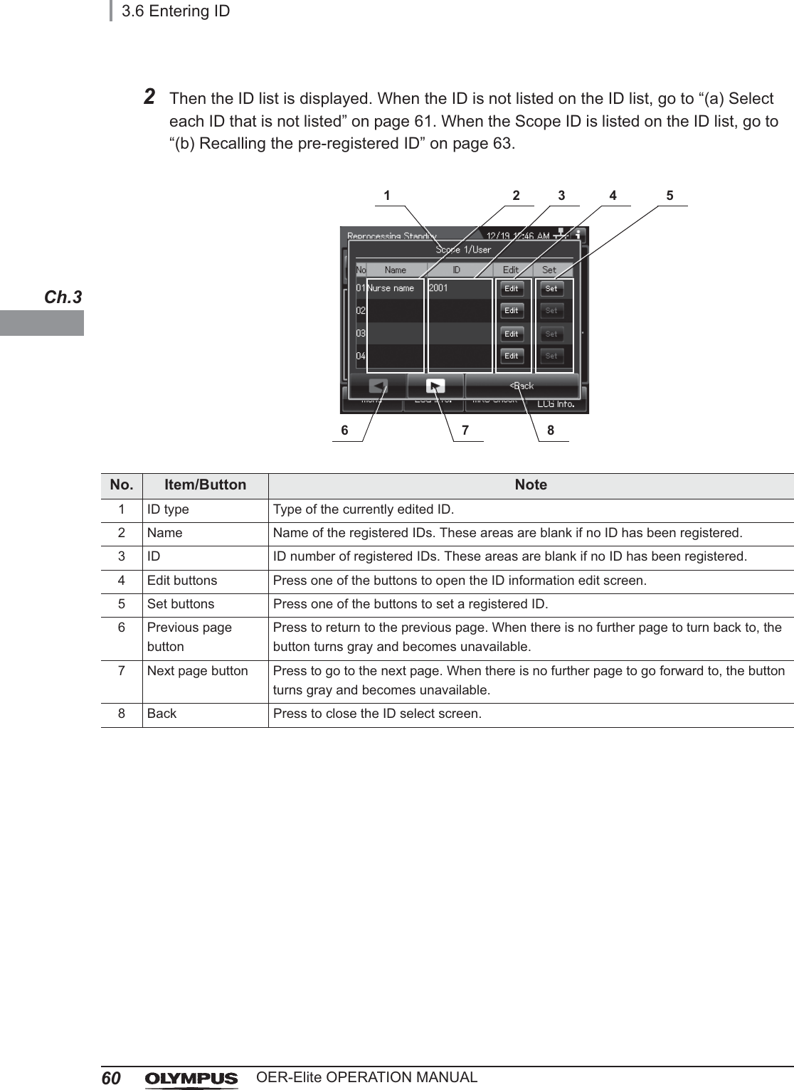
Operation Manual 1
Contents
1.
Operation Manual 1
2.
Operation Manual 2
3.
Operation Manual 3
4.
Operation Manual 4
5.
Operation Manual 5
6.
Installation Manual 1
7.
Installation Manual 2
Operation Manual 1
Navigation menu
Upload a User Manual
Namespaces
Wiki Guide
HTML
PDF
Info
Views
User Manual
Discussion / Help
Navigation
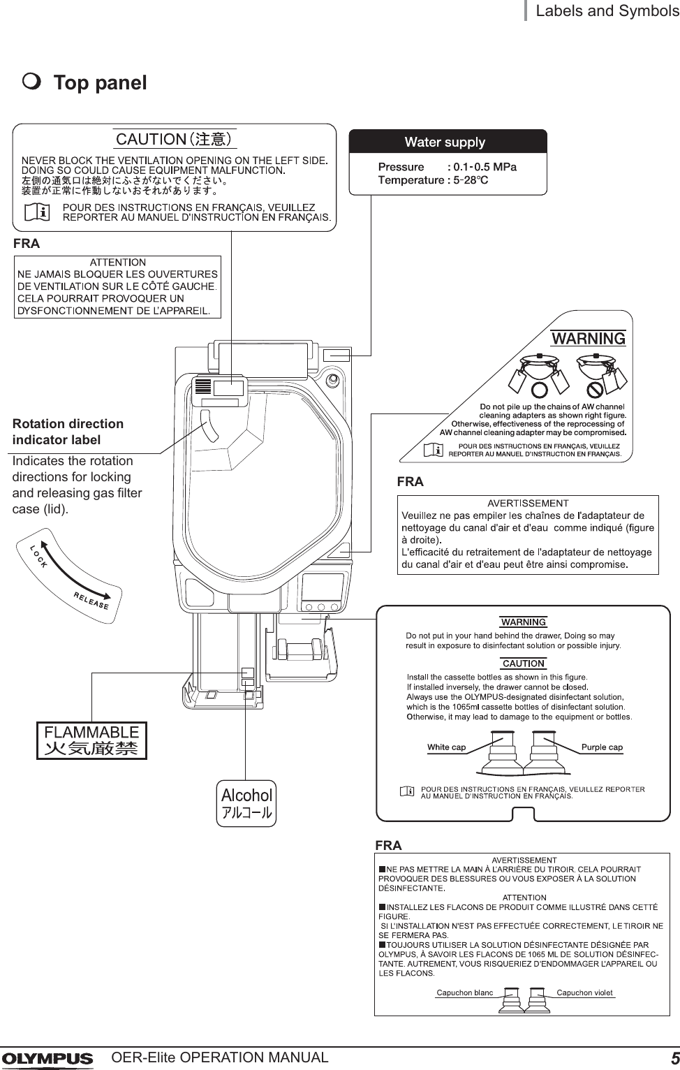
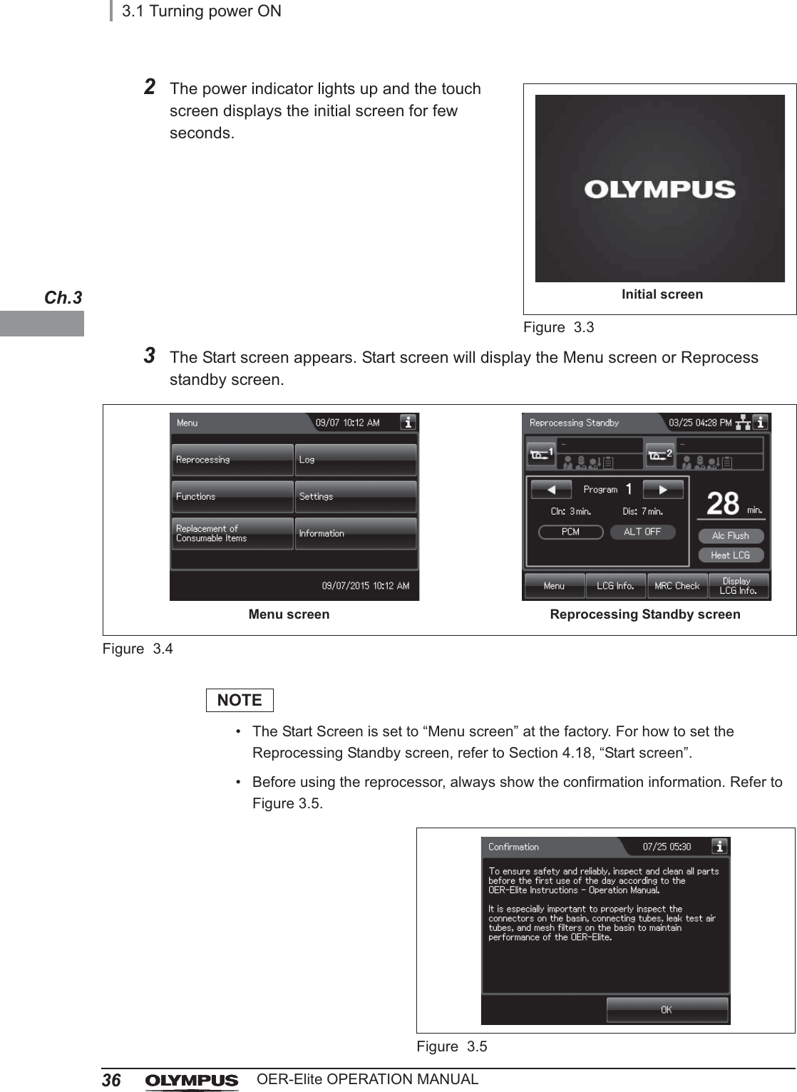
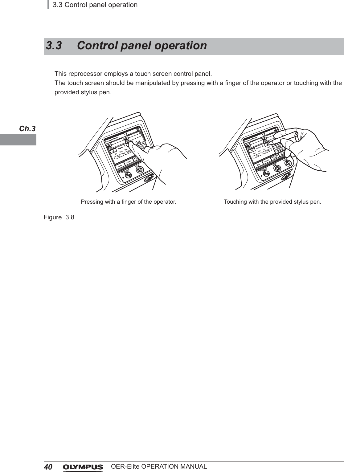
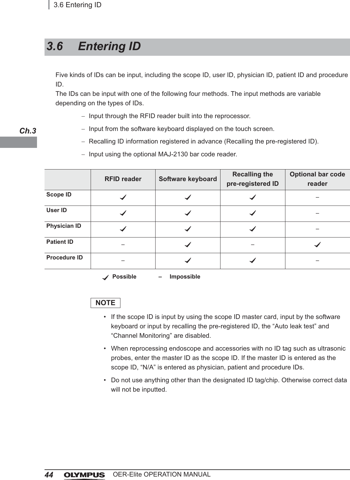
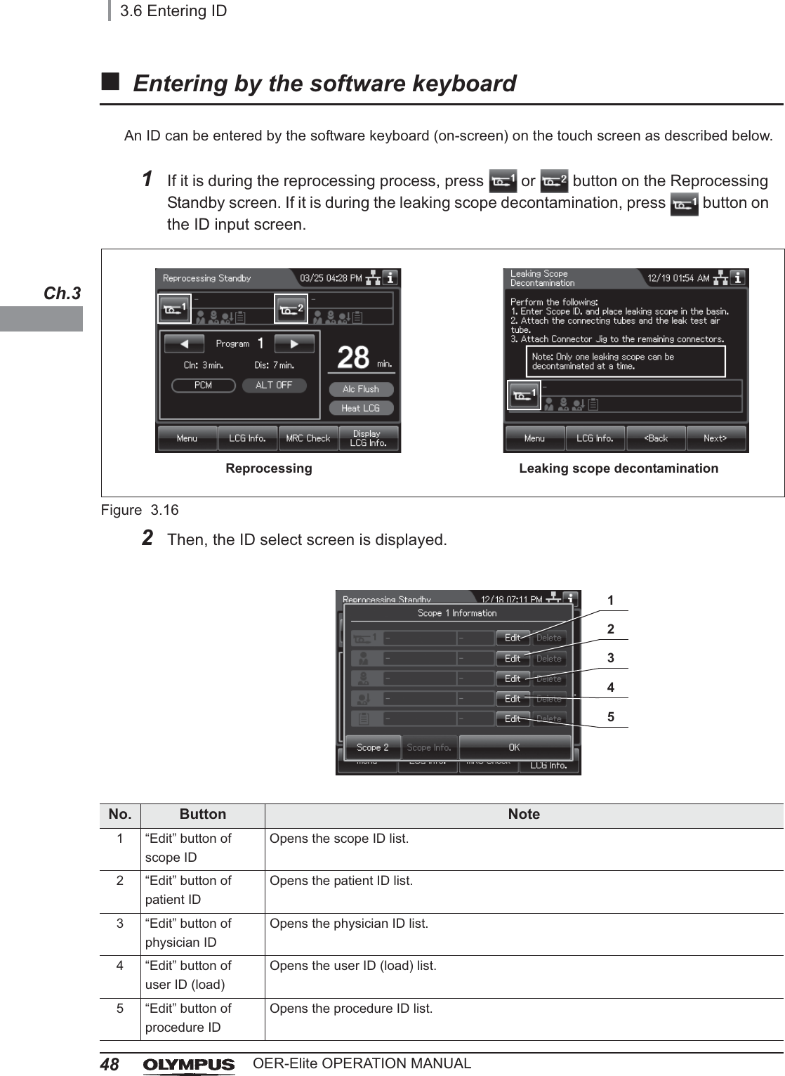
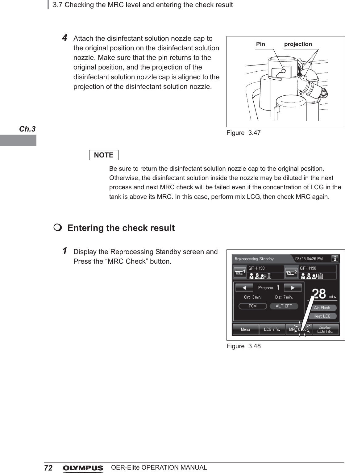
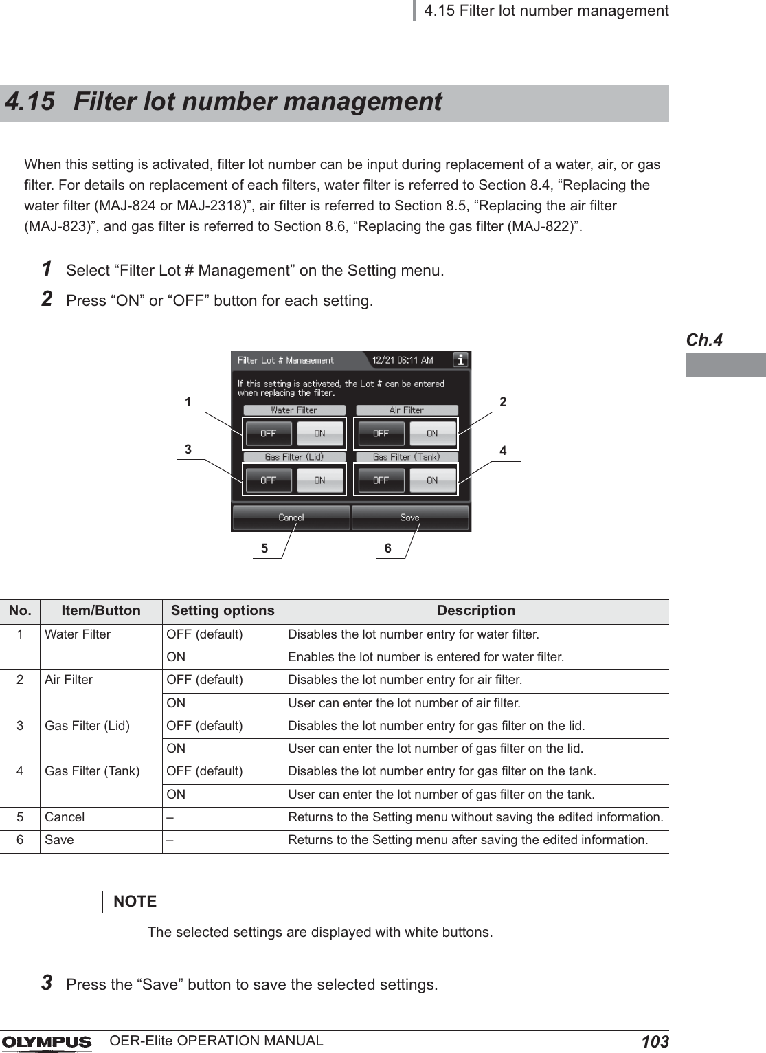
![ContentsviiOER-Elite OPERATION MANUAL10.6 Cleaning the stylus pen ....................................................................................... 460Wiping the stylus pen with alcohol ..................................................................................... 460Reprocessing together with endoscopes ........................................................................... 46010.7 Cleaning the outer surface .................................................................................. 461Chapter 11 Log Management .............................................................. 46311.1 Log menu .............................................................................................................. 46311.2 Log display and output ........................................................................................ 464Information recorded in each record .................................................................................. 47011.3 Log management with PC ................................................................................... 533Flow of electronic log management ................................................................................... 534Required item .................................................................................................................... 534Output of recorded data to the portable memory ............................................................... 535Log management on PC .................................................................................................... 54111.4 Printing records .................................................................................................... 575Printing .............................................................................................................................. 575Print format ........................................................................................................................ 579Chapter 12 Information Menu Screen ................................................. 58912.1 RFID data check .................................................................................................... 58912.2 Reprocessor information check ......................................................................... 59212.3 List management .................................................................................................. 595Chapter 13 Troubleshooting and Repair ............................................ 59913.1 Emergency stop and automatic processing after stopping ............................. 59913.2 Troubleshooting guide ......................................................................................... 600When the error code [E024] is displayed during the reprocessing process ...................... 614When any leaks are detected ............................................................................................ 617When the message screen “Message 087” is displayed ................................................... 627When the “Message 093” is displayed .............................................................................. 635Other problems and remedial actions ................................................................................ 64213.3 OER-Elite return ................................................................................................... 645Appendix ............................................................................................... 647System chart .................................................................................................................. 647Specifications ................................................................................................................ 649Shipping environment ........................................................................................................ 649Operating environment ...................................................................................................... 649Specifications ..................................................................................................................... 650EMC information ............................................................................................................ 653License information of Open Source Software ........................................................... 658License information of Open Source Software ........................................................... 670](https://usermanual.wiki/Olympus-Medical-Systems/RU2020.Operation-Manual-1/User-Guide-3575657-Page-9.png)
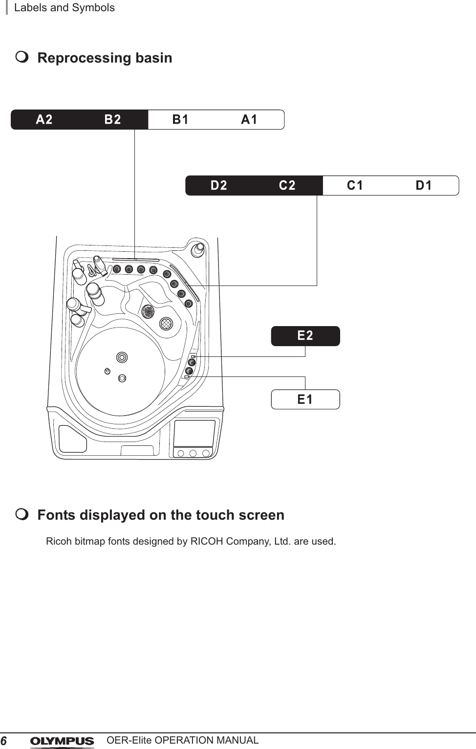
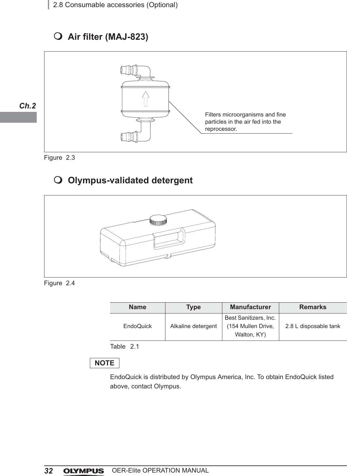
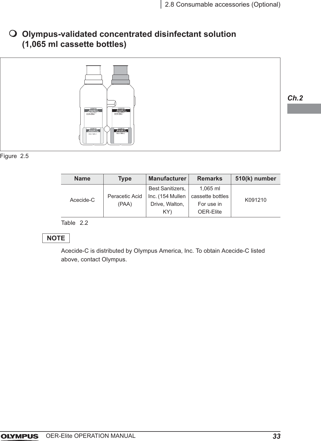
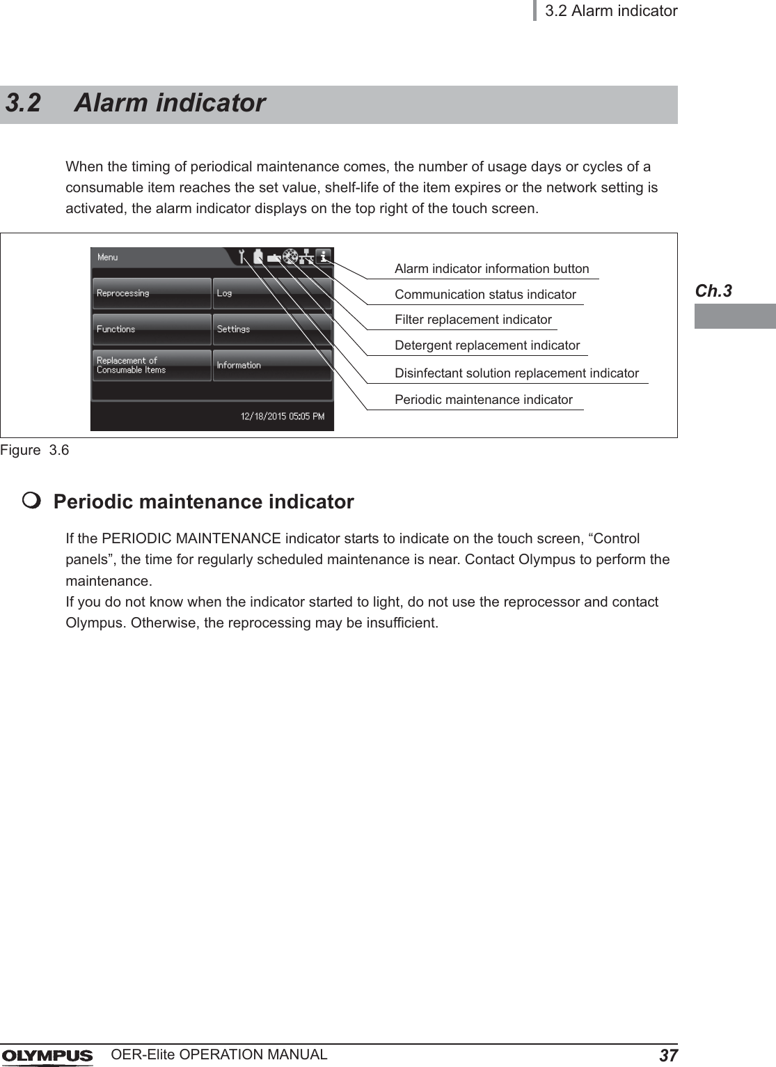
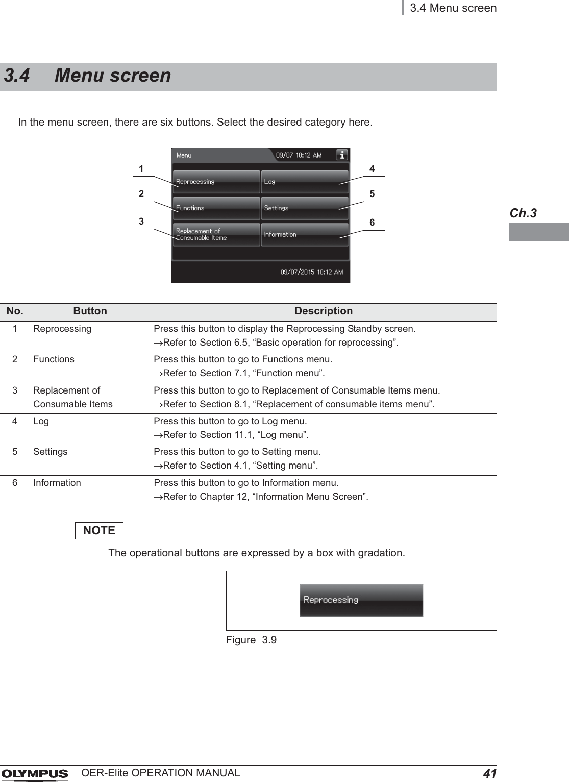
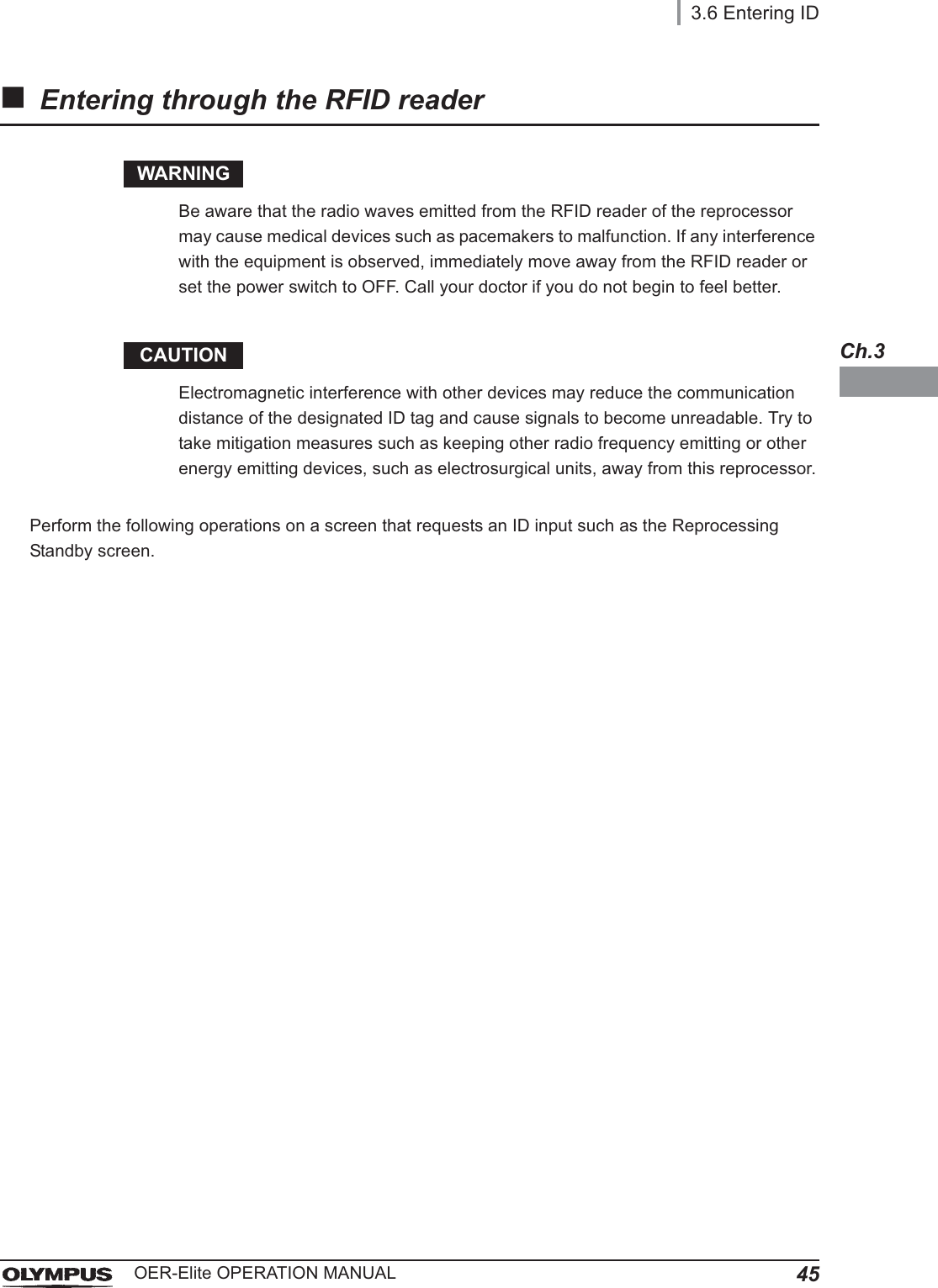
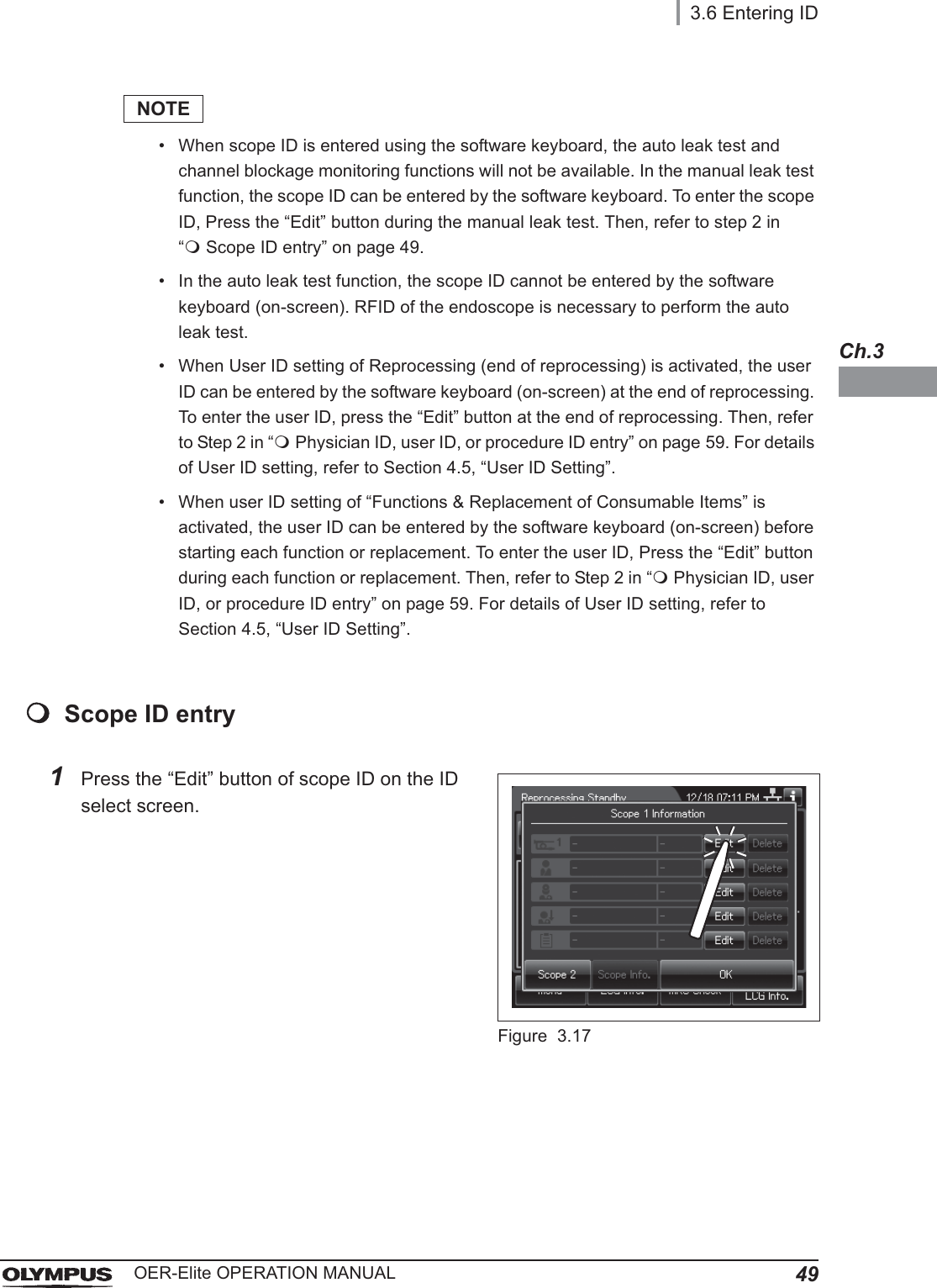
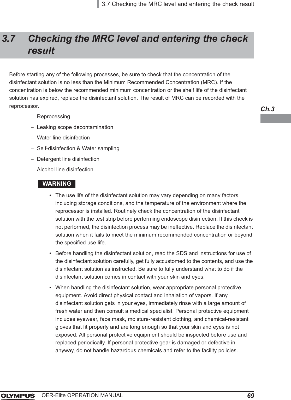
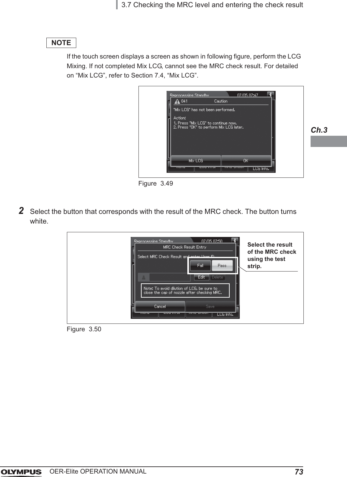
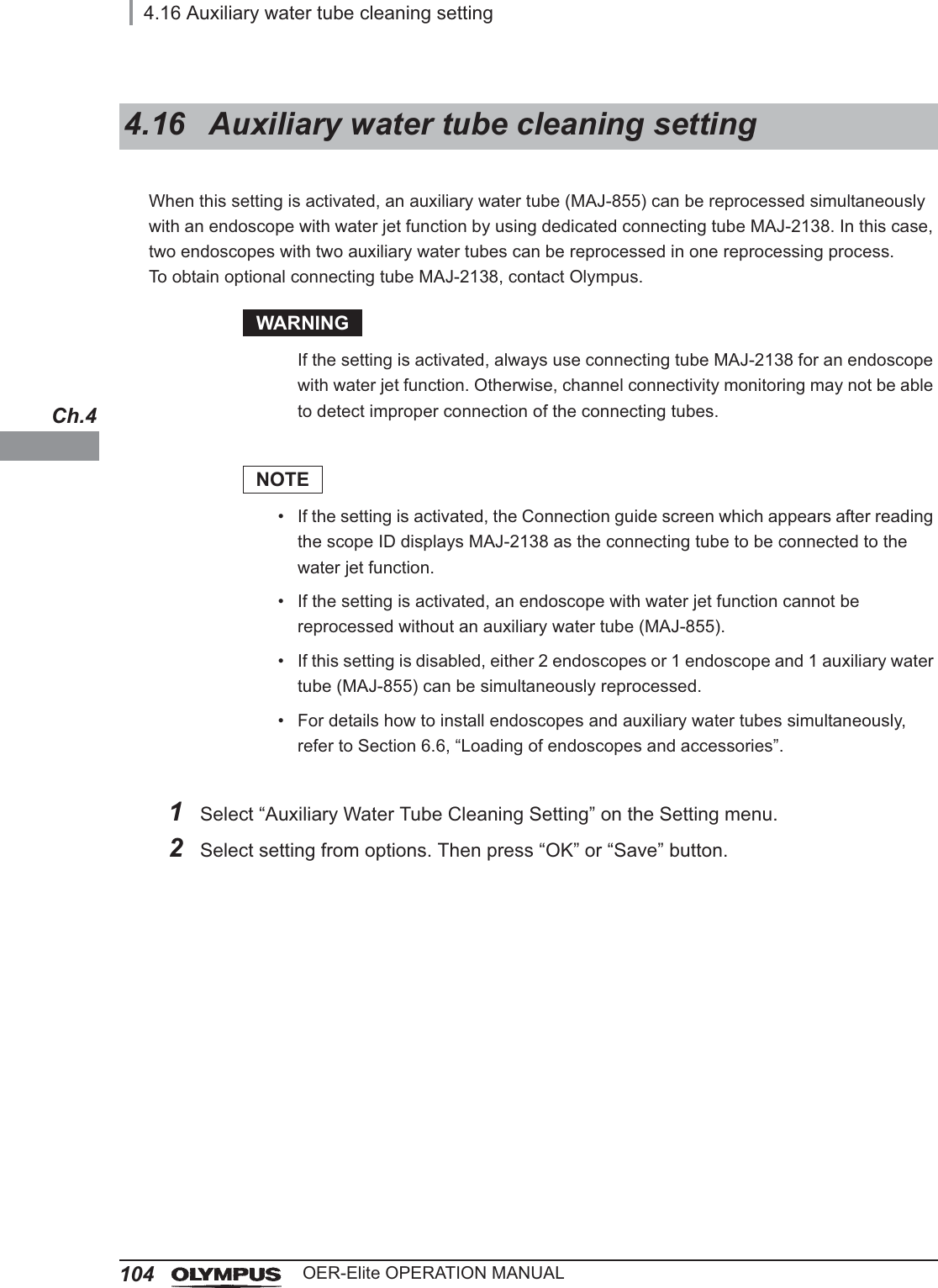
![Important Information — Please Read Before Use9OER-Elite OPERATION MANUALDetergentOlympus-validated detergent. Refer to Section 2.8, “Consumable accessories (Optional)” for details.Disinfectant solutionOlympus-validated disinfectant solution. Refer to Section 2.8, “Consumable accessories (Optional)” for details.Disinfection processA series of operations programmed into the reprocessor that enable it to perform disinfection of endoscopes.Error codeA code consisting of [E] and a three-digit number. This code is displayed on the touch screen if there is a problem with the reprocessor. When an error code is displayed, check the troubleshooting guide.LCGLiquid Chemical Germicide. It refers to disinfectant solution displayed on GUI.Leak testA test to confirm that an endoscope is free of leaks. This reprocessor is capable of both the auto leak test and the manual leak test.Manual cleaningCleaning of an endoscope by hand.Modified precleaning and manual cleaningA precleaning and manual cleaning method that is simplified due to subsequent use of the OER-Elite which automates cleaning steps in the process.MRCMinimum Recommended Concentration.Patient IDIdentity information specific to each patient. It can be recorded in the histories of reprocessing, etc. For the patient ID input method, refer to Section 3.6, “Entering ID”.Physician IDIdentity information specific to each endoscopist. It can be recorded in the histories of reprocessing, etc. For the physician ID input method, refer to Section 3.6, “Entering ID”.Portable memoryA digital medium for storage.](https://usermanual.wiki/Olympus-Medical-Systems/RU2020.Operation-Manual-1/User-Guide-3575657-Page-19.png)
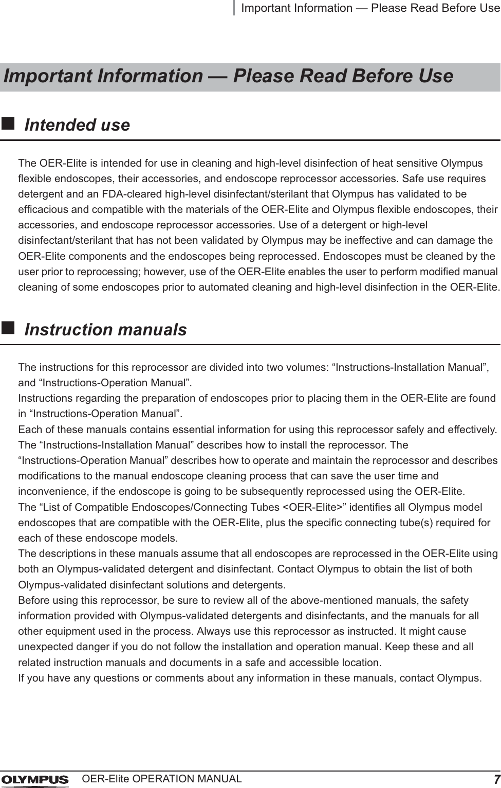
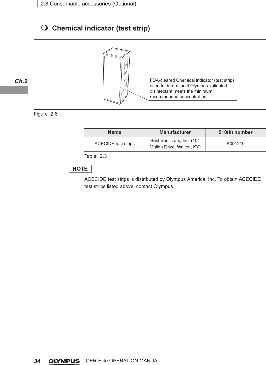
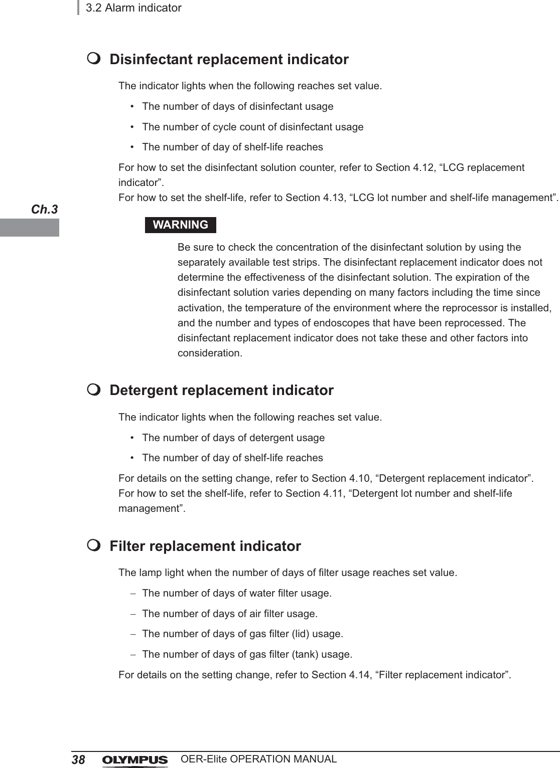
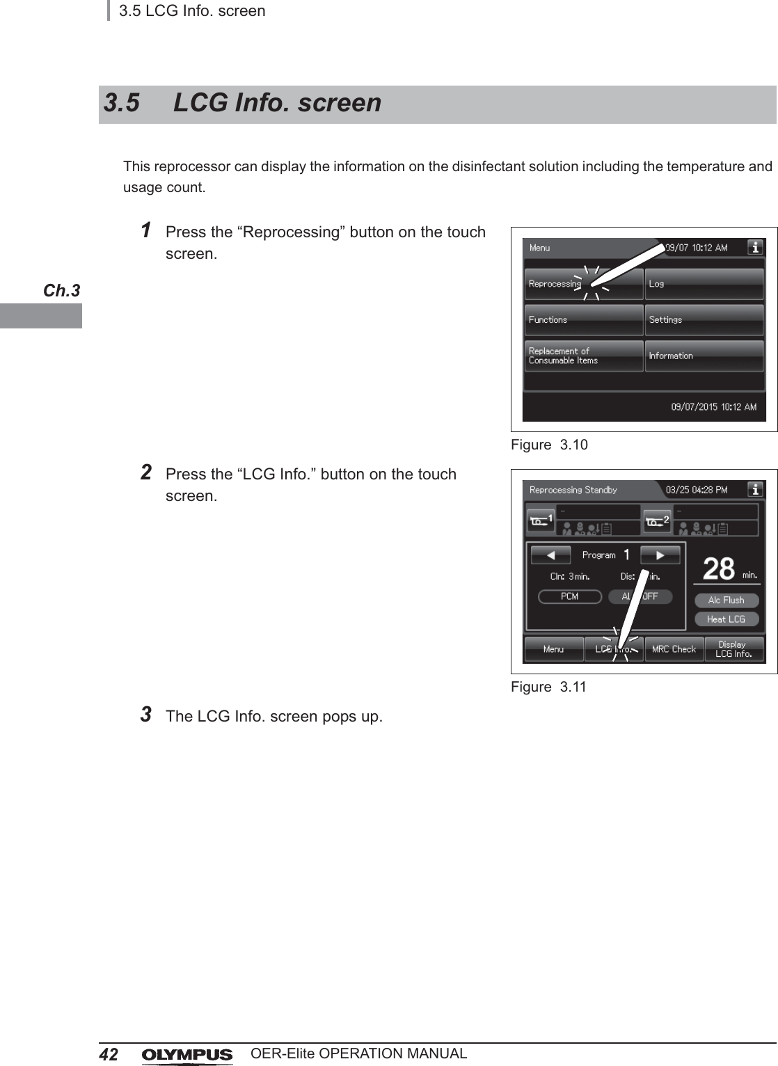
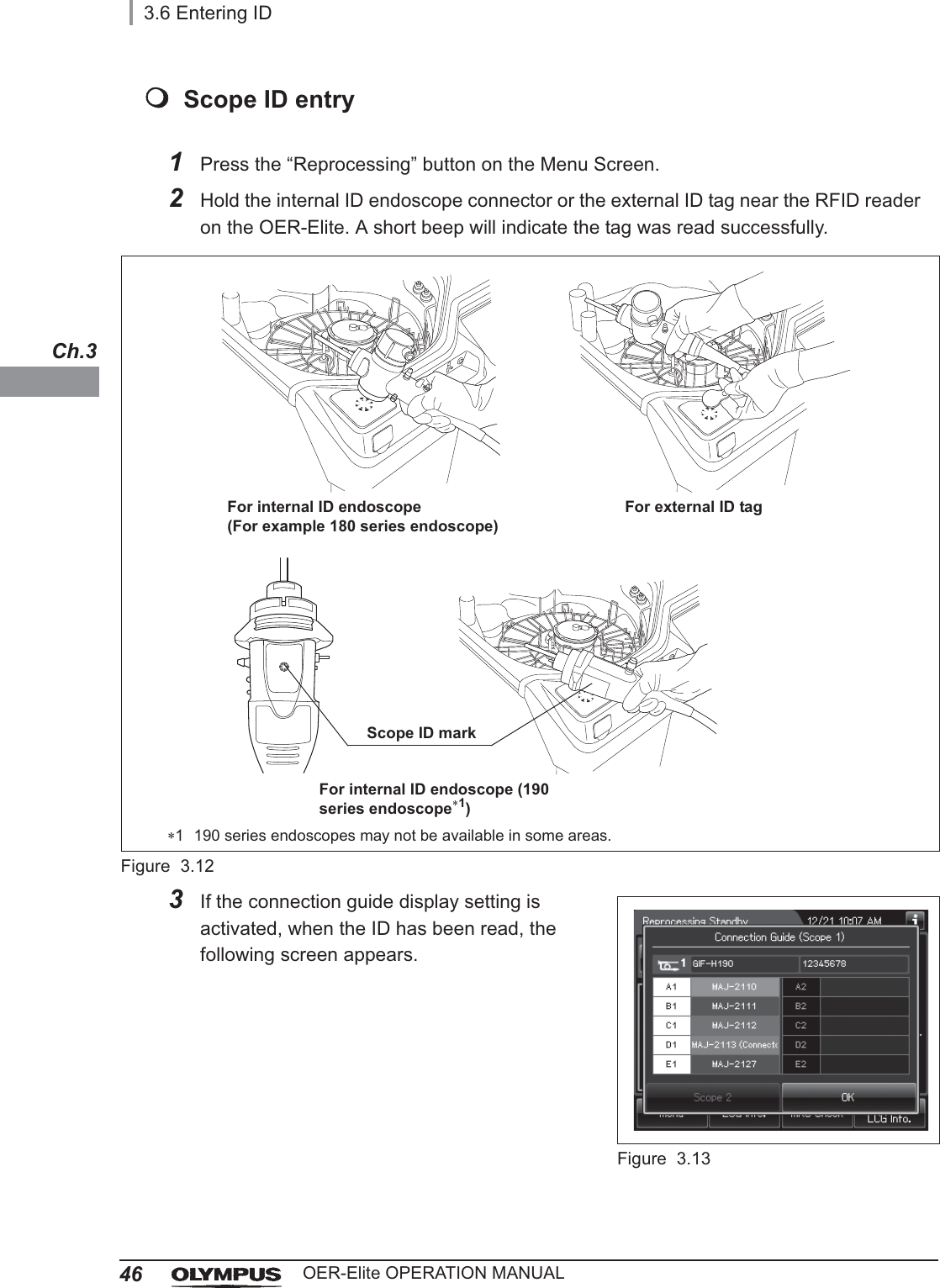
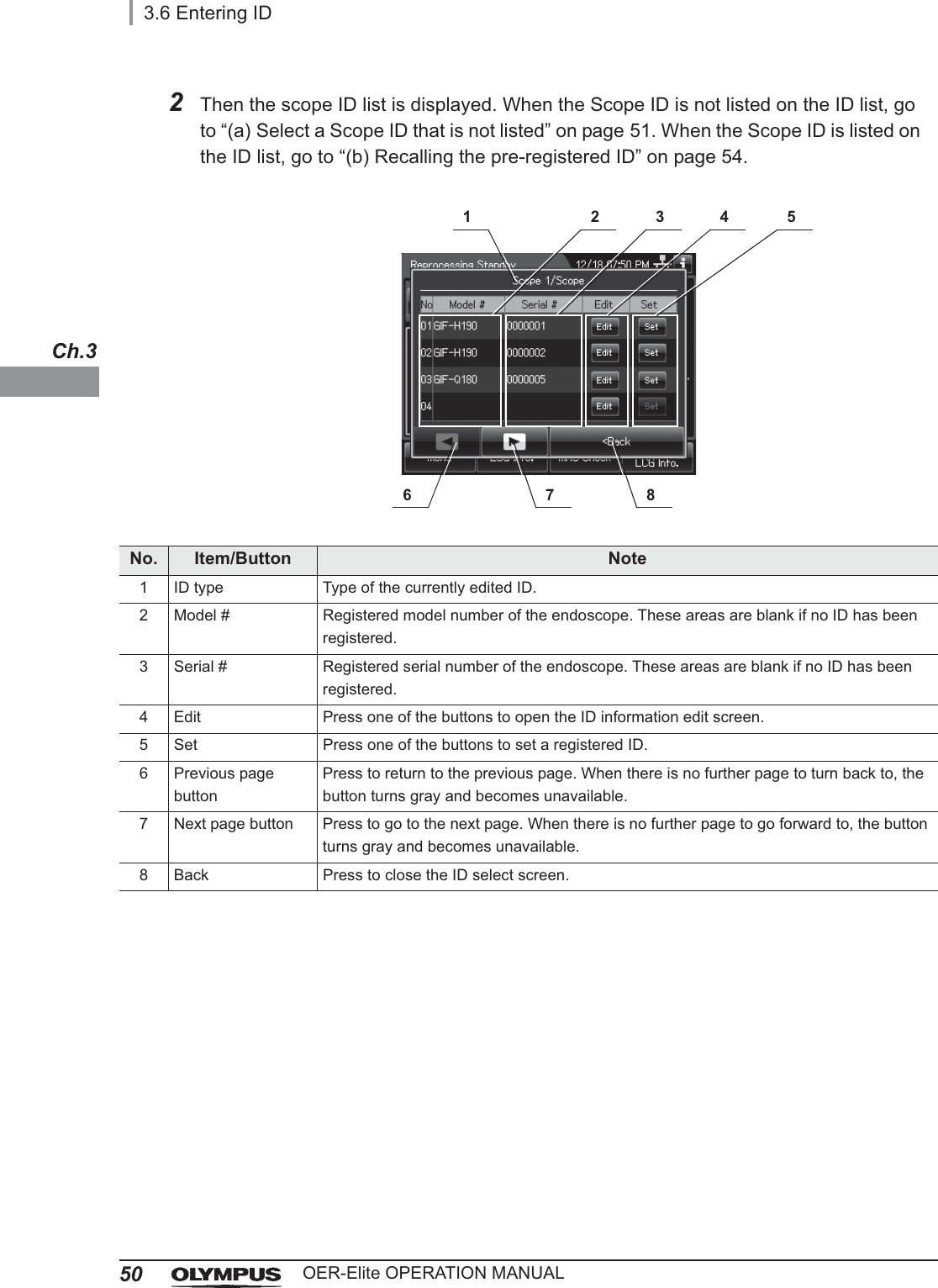
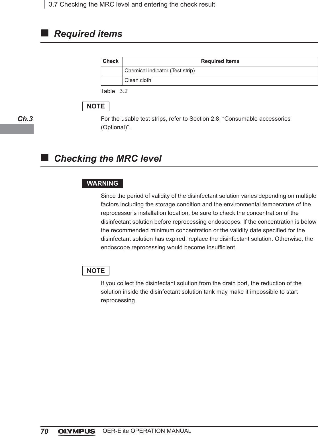
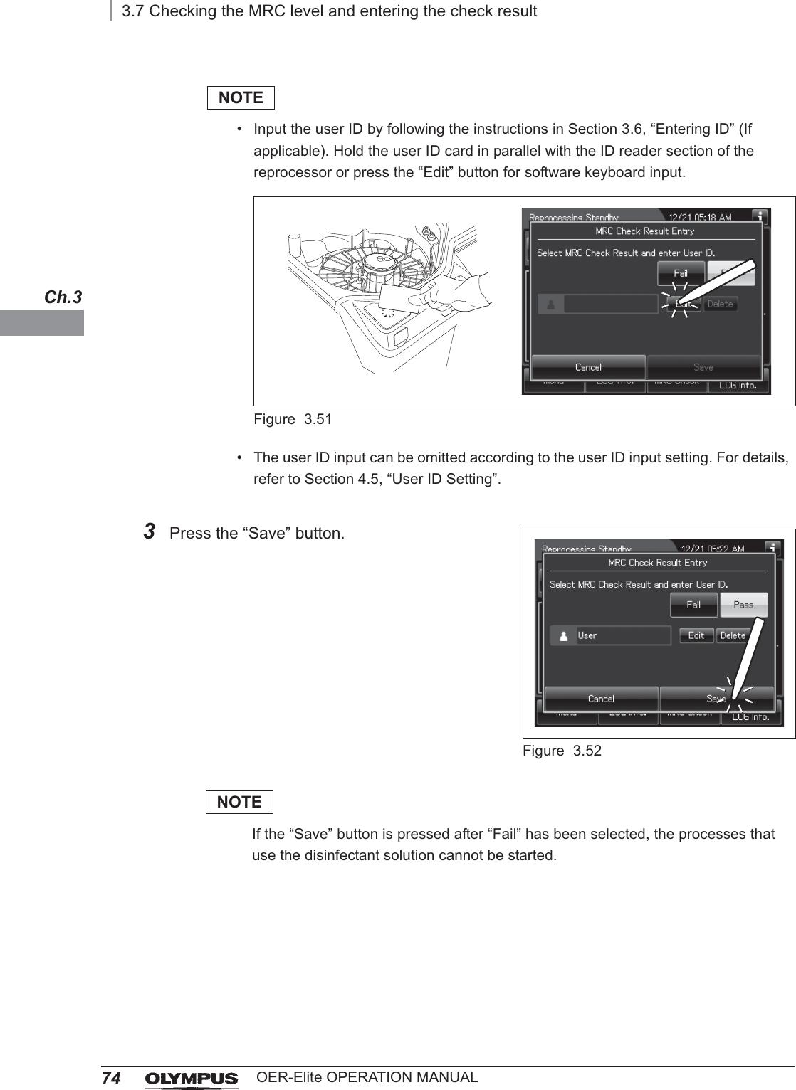
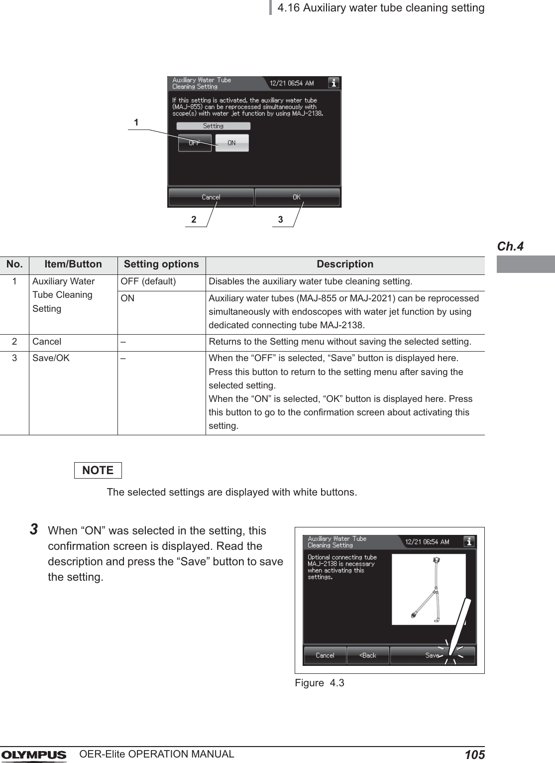
![10Important Information — Please Read Before UseOER-Elite OPERATION MANUALPrecleaningCleaning of an endoscope performed after each procedure at the bedside in the endoscopy room.Procedure IDIdentity information specific to each procedure of the patient. It can be recorded in the histories of reprocessing, etc. For the procedure ID input method, refer to Section 3.6, “Entering ID”.ProcessGeneric term for any operation, including cleaning and disinfection that is performed automatically by this reprocessor.Reprocessing processA series of operations for ultrasonic cleaning, detergent cleaning, disinfection, rinse, air purge, and alcohol flush of the outer surface or channels of endoscopes that run in a specified sequence and for a specified time. Reprocessing programs [1] to [4] can be selected by the user. Programs [1] to [4] have a fixed cleaning process time and disinfection process time. They also have different patterns of auto leak test and channel monitoring respectively.Scope IDIdentity information specific to each endoscope. It can be recorded in the historical data of reprocessing, etc. For the scope ID input method, refer to Section 3.6, “Entering ID”.Shelf lifeThe date of expiration of the effectiveness of a detergent or disinfectant before it is opened.Test stripDevice used to test if the concentration of disinfectant solution is effective for disinfection. Refer to Section 2.8, “Consumable accessories (Optional)” for details. (i.e., the minimum recommended concentration (MRC) specified by the disinfectant manufacturer)User IDIdentity information specific to each reprocessing operator. It can be recorded in the histories of reprocessing, etc. For the user ID input method, refer to Section 3.6, “Entering ID”.](https://usermanual.wiki/Olympus-Medical-Systems/RU2020.Operation-Manual-1/User-Guide-3575657-Page-20.png)
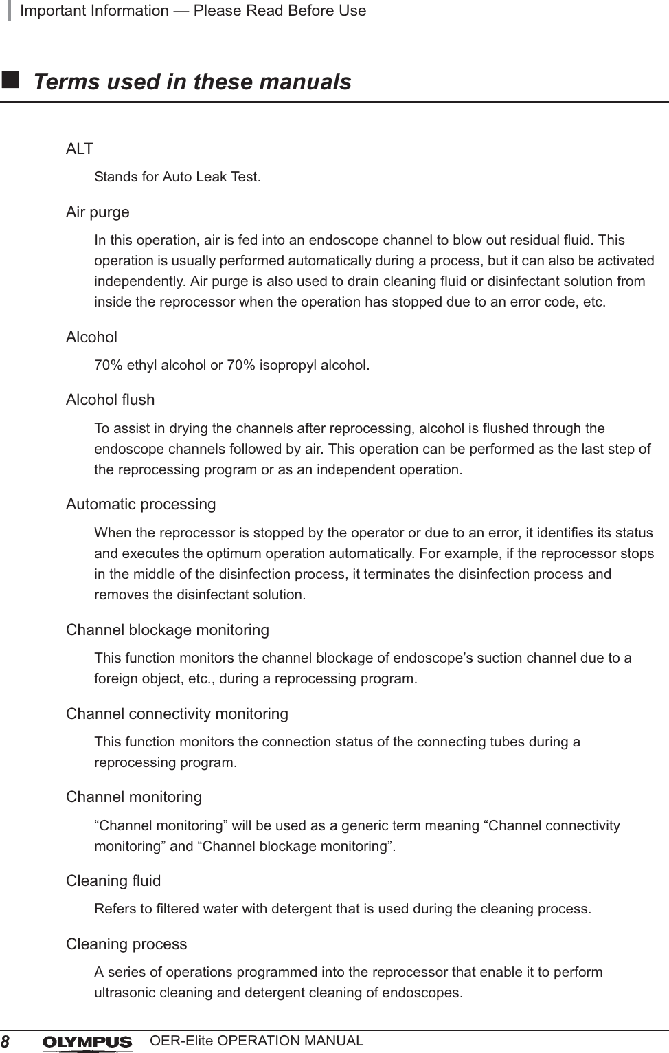
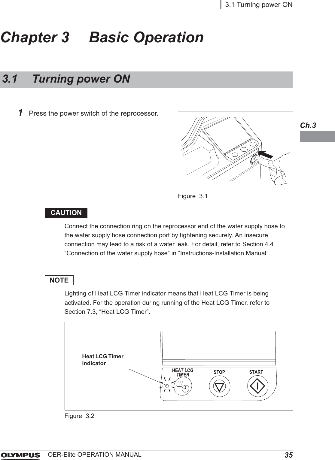
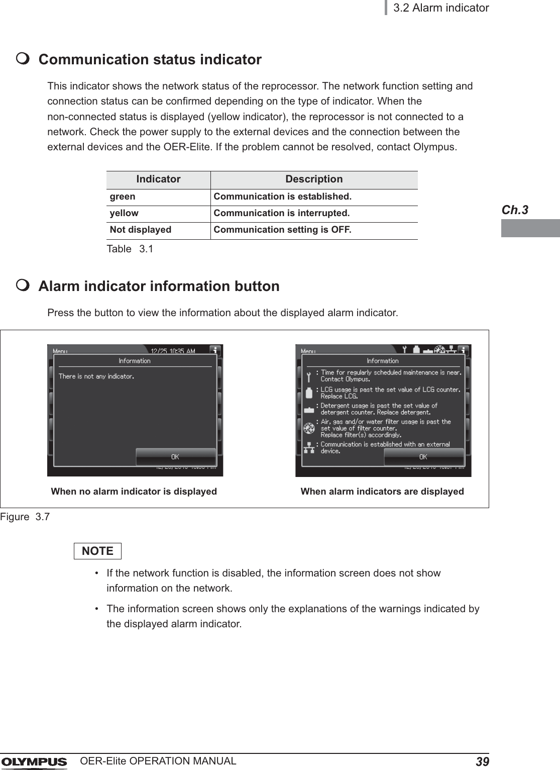
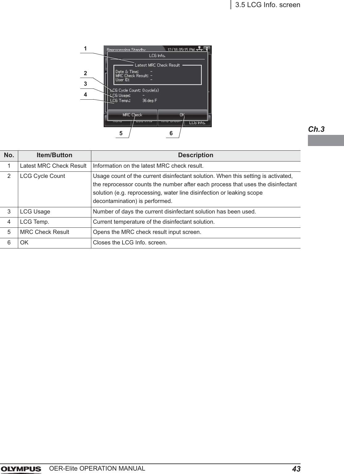
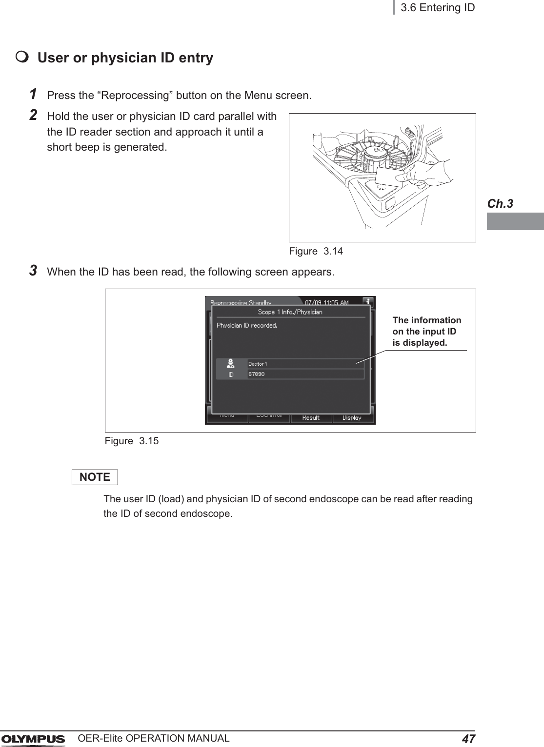
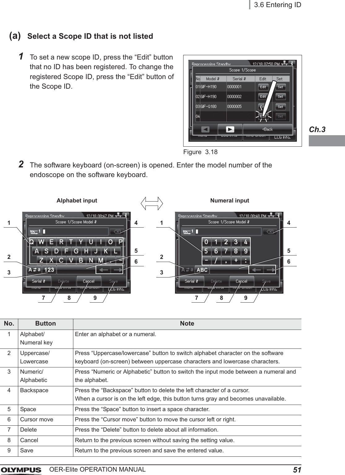
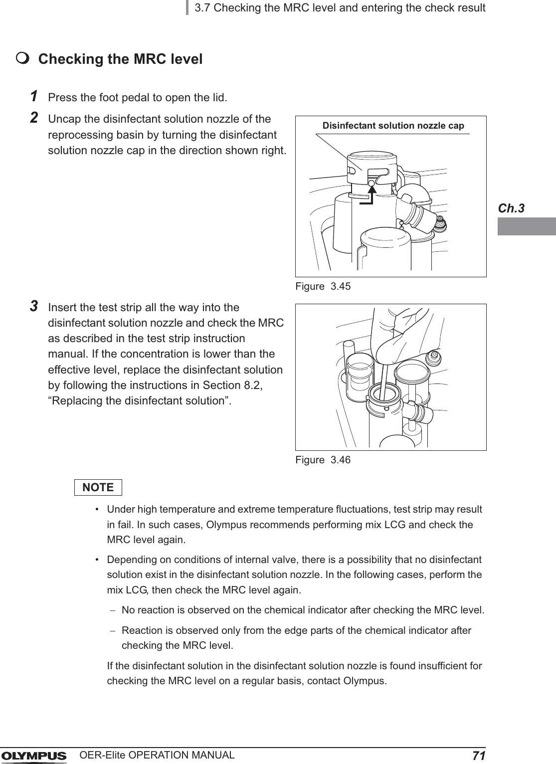
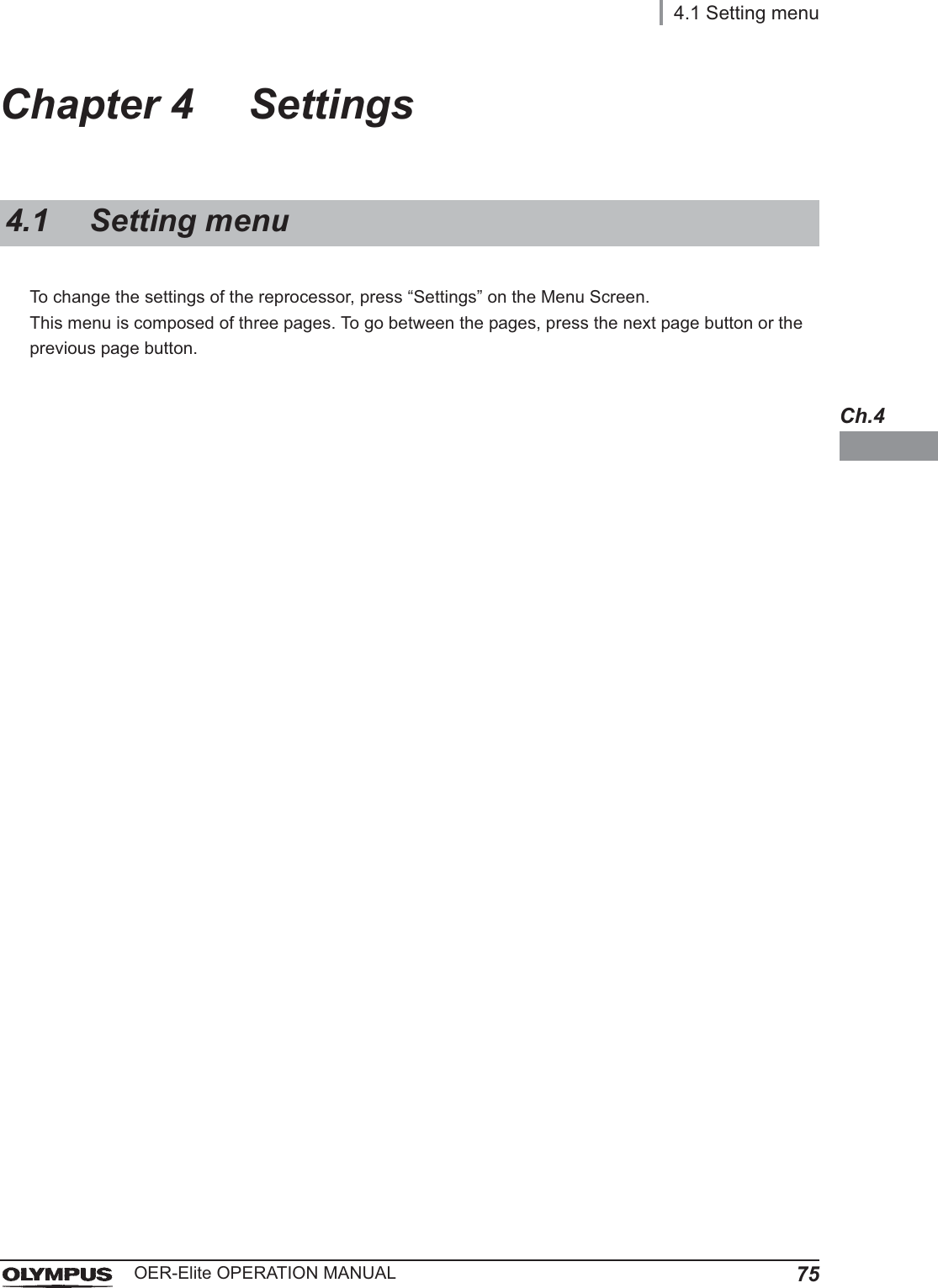
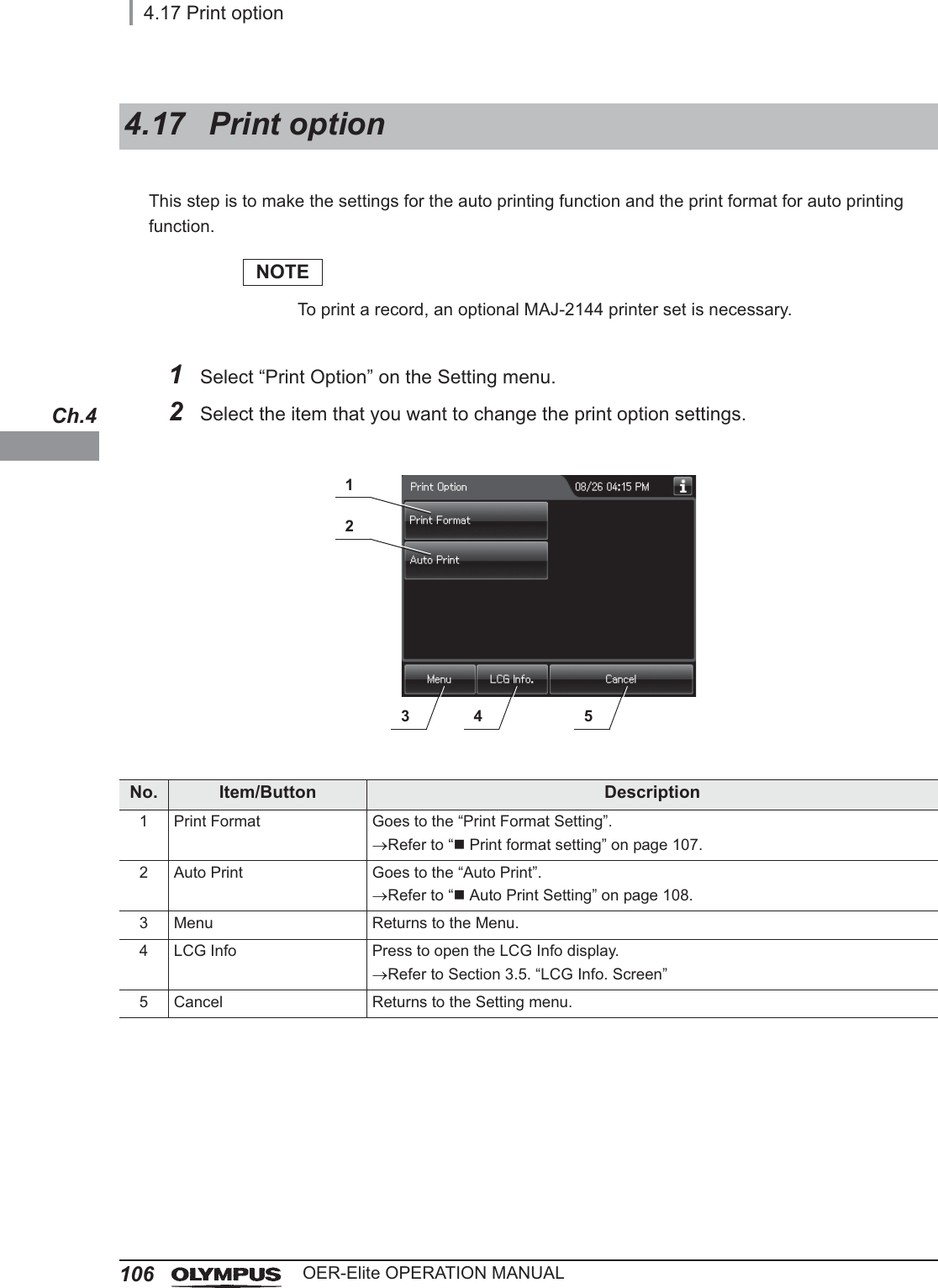
![16Outline of FunctionsOER-Elite OPERATION MANUALFollowing functions are available in this reprocessor.ReprocessingA series of operations that enable the reprocessor to perform ultrasonic cleaning, detergent cleaning, disinfection, rinse, air purge, and alcohol flush. A series of operations for ultrasonic cleaning, detergent cleaning, disinfection, rinse, air purge, and alcohol flush of the outer surface and channels of endoscopes in a specified sequence and for a specified time. Reprocessing programs [1] to [4] can be selected by the user. Programs [1] to [4] have a fixed cleaning process time and disinfection process time. They also have different patterns of auto leak test and channel monitoring respectively. For details, refer to Chapter 6, “Reprocessing Operations”.Heat LCGA process for heating disinfectant solution until it reaches the specified temperature (22q, 72qF). This process is performed automatically during the reprocessing program. It can also be performed as an independent operation. For details, refer to Section 7.2, “Heat LCG”.Heat LCG TimerThe function for heating the disinfectant solution until the specified temperature (22q, 72qF) by the specified time. For details, refer to Section 7.3, “Heat LCG Timer”.Drain LCGThis function drains the disinfectant solution from the disinfectant tank. For details, refer to Section 8.2, “Replacing the disinfectant solution”.Load LCGThis function loads the disinfectant solution after inserting a new disinfectant bottle. For details, refer to Section 8.2, “Replacing the disinfectant solution”.Mix LCGThis function mixs the disinfectant solution to the appropriate concentration and enables accurate concentration check.Outline of Functions](https://usermanual.wiki/Olympus-Medical-Systems/RU2020.Operation-Manual-1/User-Guide-3575657-Page-26.png)


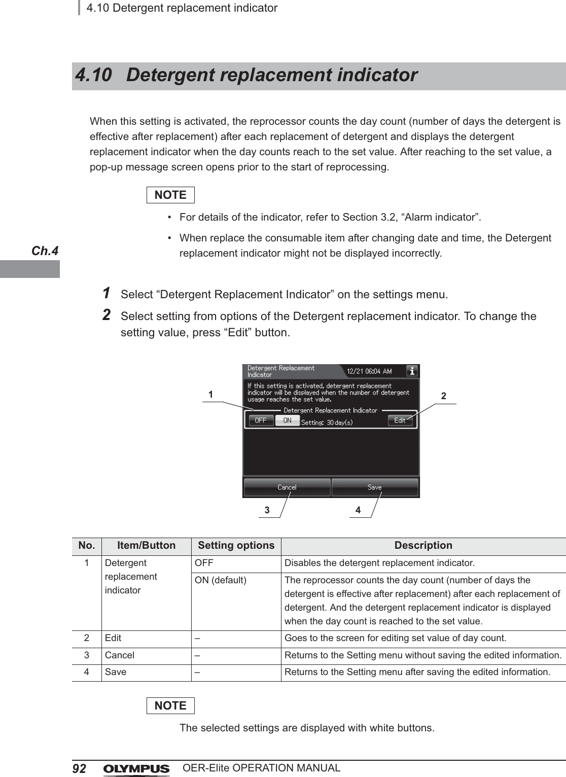
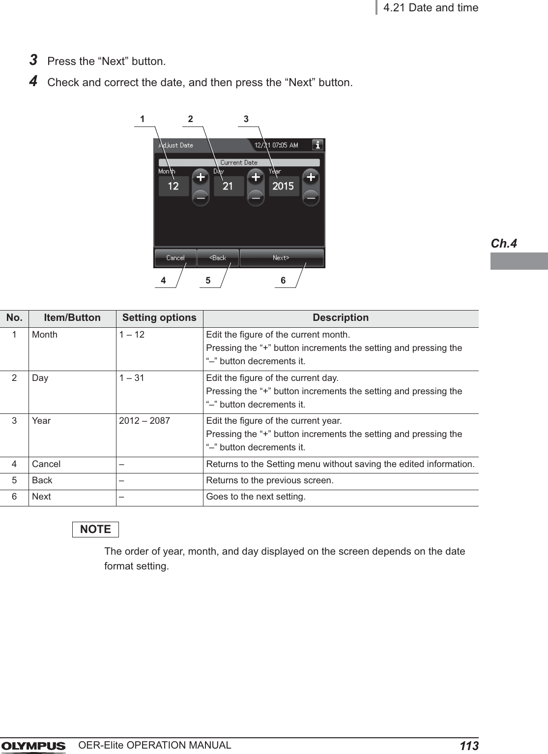
![4.10 Detergent replacement indicator93OER-Elite OPERATION MANUALCh.4NOTEFor details of the indicator, refer to Section 3.2, “Alarm indicator”.3If “Edit” button is pressed in the previous screen, following screen is displayed. Edit the number of days, and press “OK” button.No. Item/Button Setting options Description1 Days 1 – 30 [days] (default: 30)Sets the set value of days for the detergent replacement indicator.Pressing the “+” button increments the setting and pressing the “–” button decrements it.2 Cancel – Returns to the previous screen without saving the edited information.3 OK – Returns to the previous menu after saving the edited information.4Press the “Save” button to return to the Setting menu after saving the edited information.Figure 4.112 3](https://usermanual.wiki/Olympus-Medical-Systems/RU2020.Operation-Manual-1/User-Guide-3575657-Page-103.png)
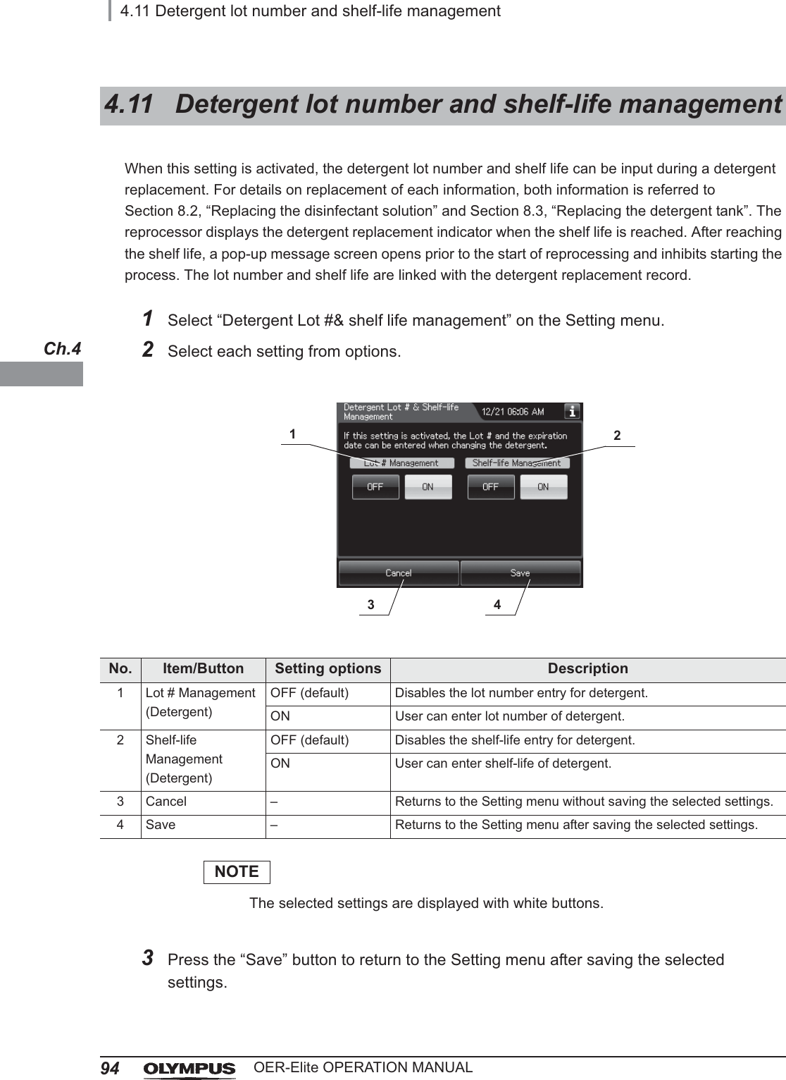
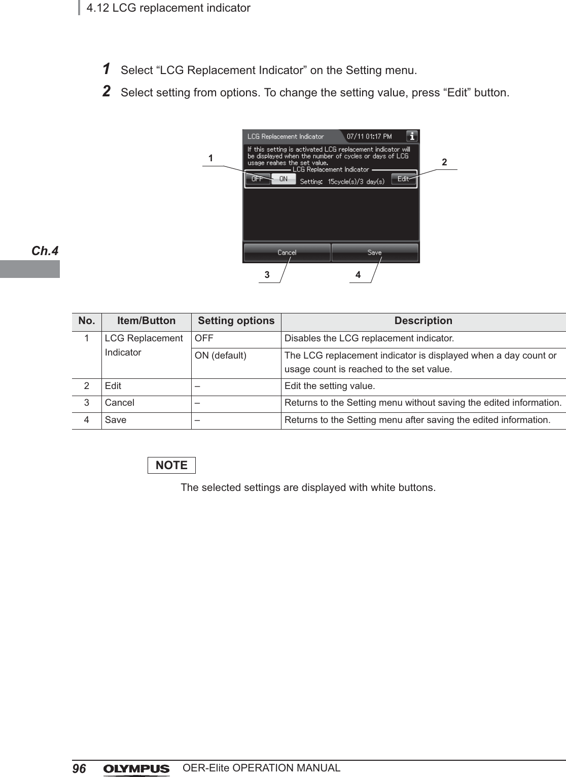
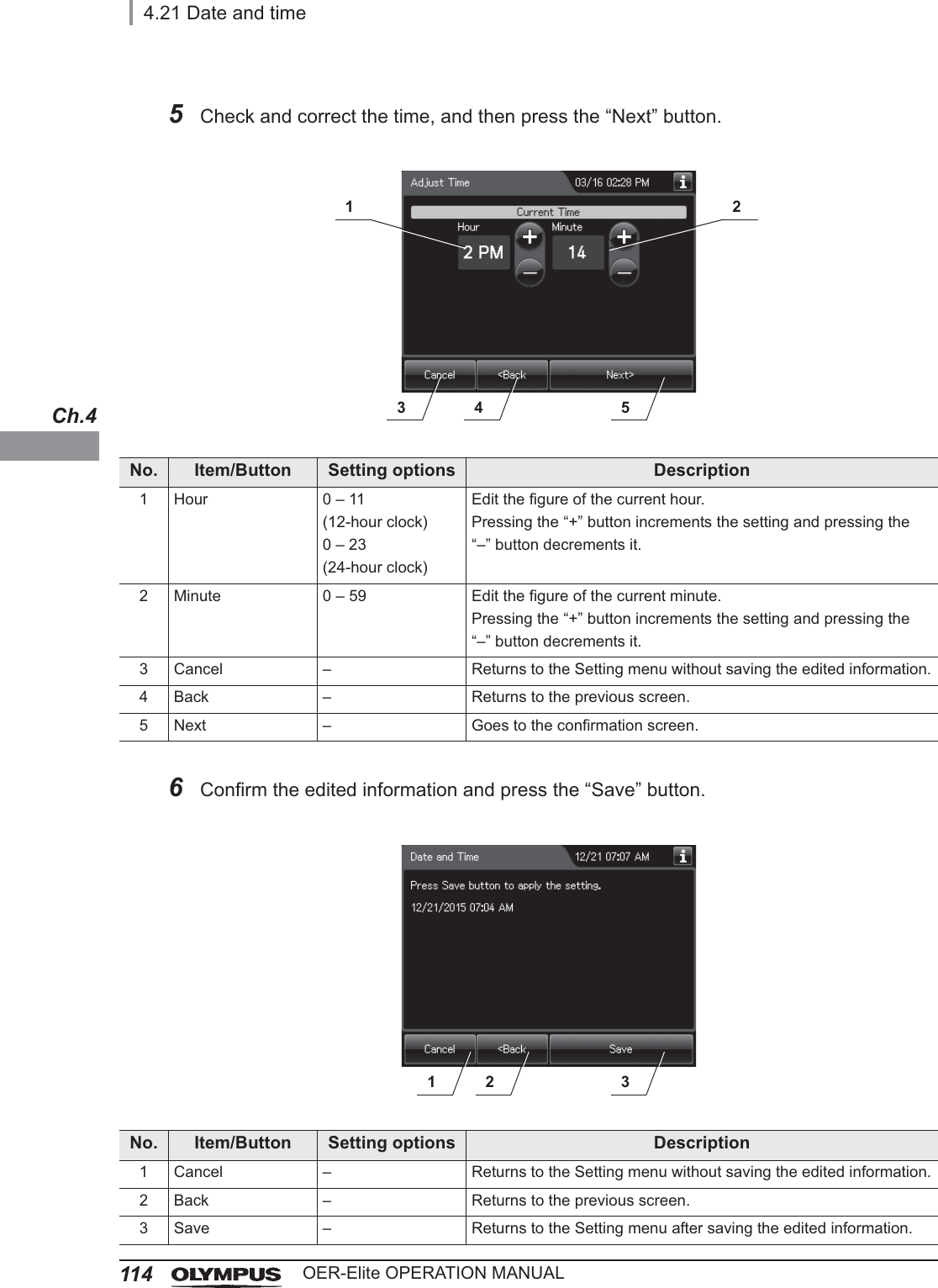
Sets the set value of days for the LCG replacement indicator.Pressing the “+” button increments the setting and pressing the “–” button decrements it.2 Cycles 1 – 35 [usages](default: 15)Sets the set value of cycles for the LCG replacement indicator.Pressing the “+” button increments the setting and pressing the “–” button decrements it.3 Cancel – Returns to the Setting menu without saving the edited information.4 OK – Returns to the Setting menu after saving the edited information.4Press the “Save” button to return to the Setting menu after saving the edited information.Figure 4.213 42](https://usermanual.wiki/Olympus-Medical-Systems/RU2020.Operation-Manual-1/User-Guide-3575657-Page-107.png)
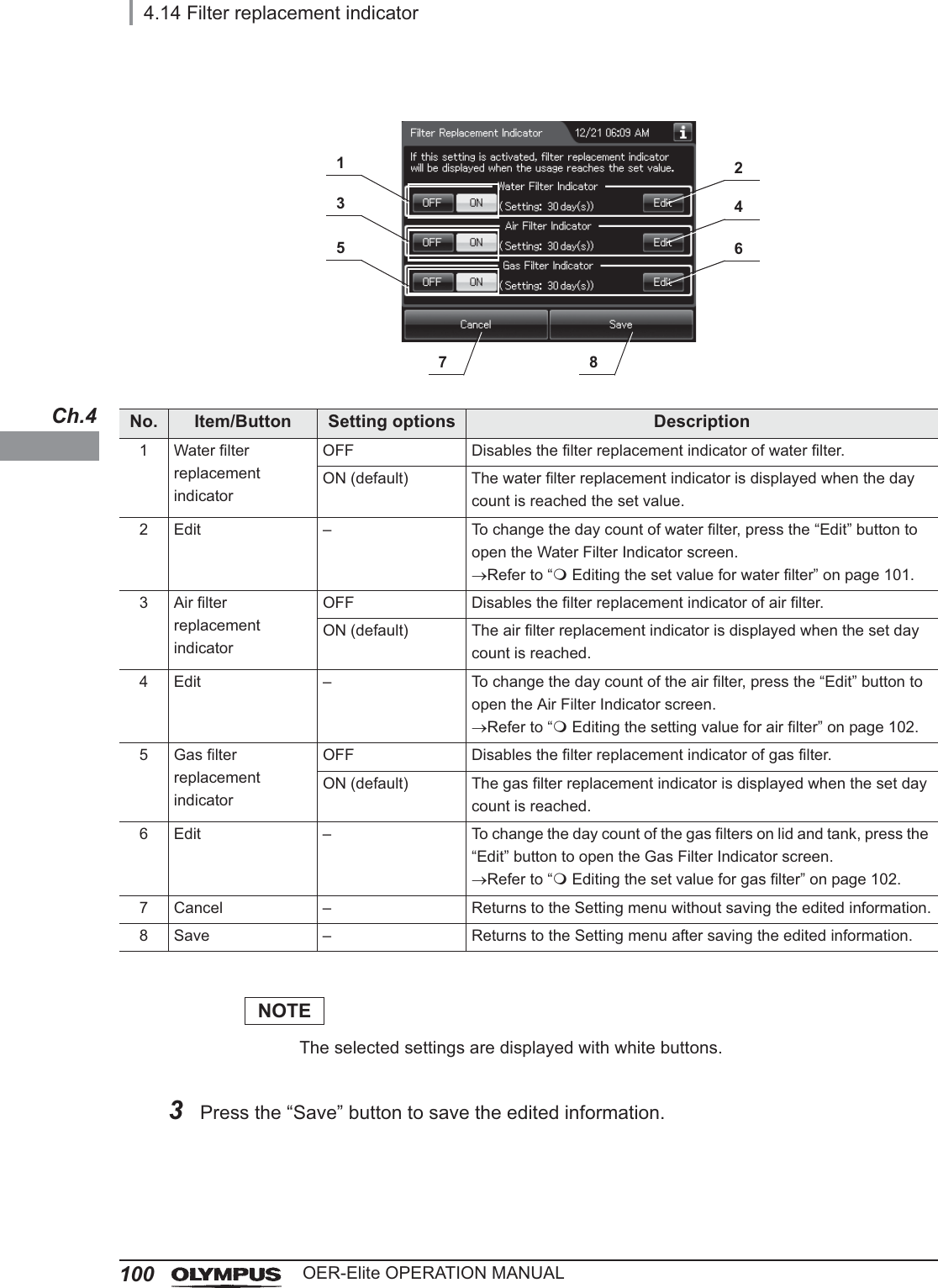
![4.14 Filter replacement indicator101OER-Elite OPERATION MANUALCh.4Editing the set value for water filterNOTEThe selected settings are displayed with white buttons.No. Item/Button Setting options Description1 Pre-filtering With the pre-filter When the pre-filter is used, select this option to expand the setting range of day count up 180 days.Without the pre-filter (default)When the pre-filter is not used, select this option to restrict the setting range of day count 30 days.2 Days 1 – 180 [days] or1 – 30 [days] (default: 30)Sets the set value of days for the filter replacement indicator of water filter.Pressing the “+” button increments the setting and pressing the “–” button decrements it.The setting range varies depending on the usage of pre-filter.3 Cancel – Returns to the previous screen without saving the edited information.4 OK – Returns to the previous screen after saving the edited information.1324](https://usermanual.wiki/Olympus-Medical-Systems/RU2020.Operation-Manual-1/User-Guide-3575657-Page-111.png)
![1024.14 Filter replacement indicatorOER-Elite OPERATION MANUALCh.4Editing the setting value for air filterEditing the set value for gas filterNo. Item/Button Setting options Description1 Days 1 – 30 [days] (default: 30)Sets the set value of days for the filter replacement indicator of air filter.Pressing the “+” button increments the setting and pressing the “–” button decrements it.2 Cancel – Returns to the previous screen without saving the edited information.3 Save – Returns to the previous screen after saving the edited information.No. Item/Button Setting options Description1 Days 1 – 30 [days] (default: 30)Sets the set value of days for the filter replacement indicator of gas filter.Pressing the “+” button increments the setting and pressing the “–” button decrements it.2 Cancel – Returns to the Setting menu without saving the edited information.3 Save – Returns to the Setting menu after saving the edited information.2 31213](https://usermanual.wiki/Olympus-Medical-Systems/RU2020.Operation-Manual-1/User-Guide-3575657-Page-112.png)
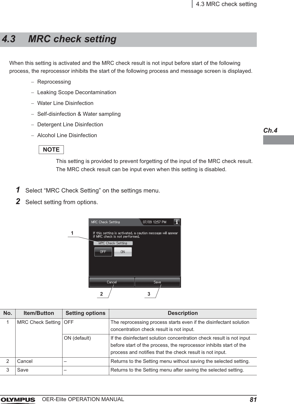
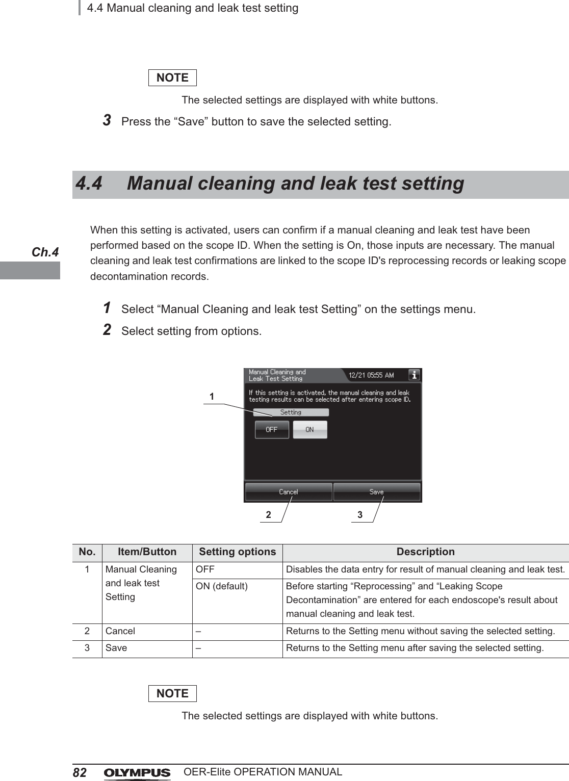
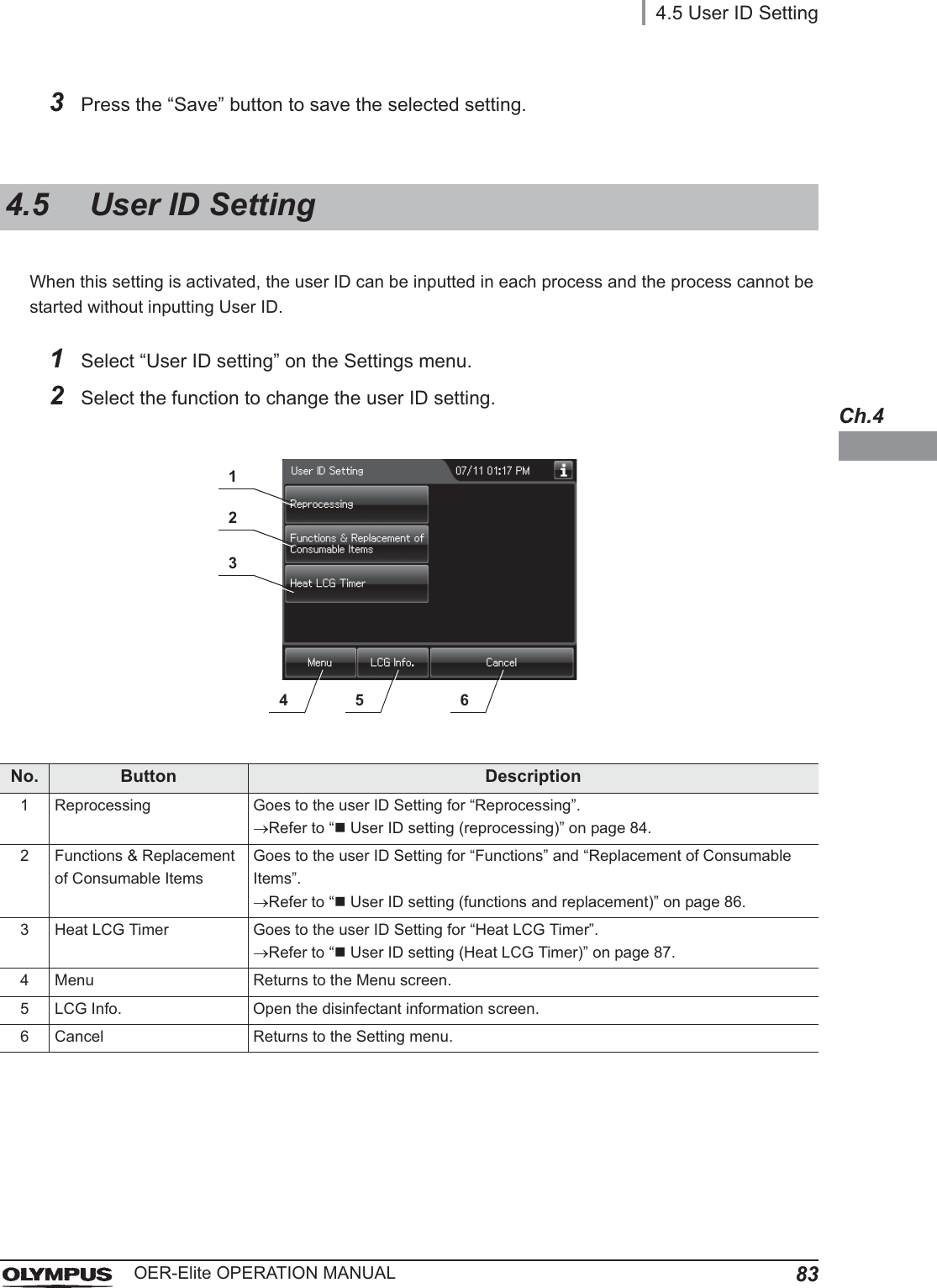
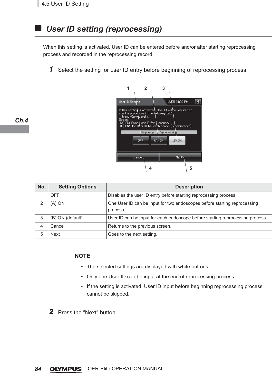
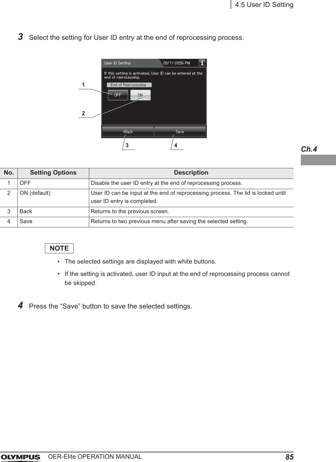
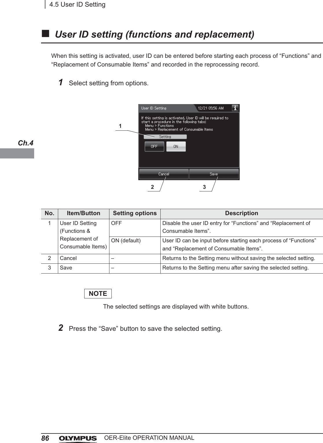
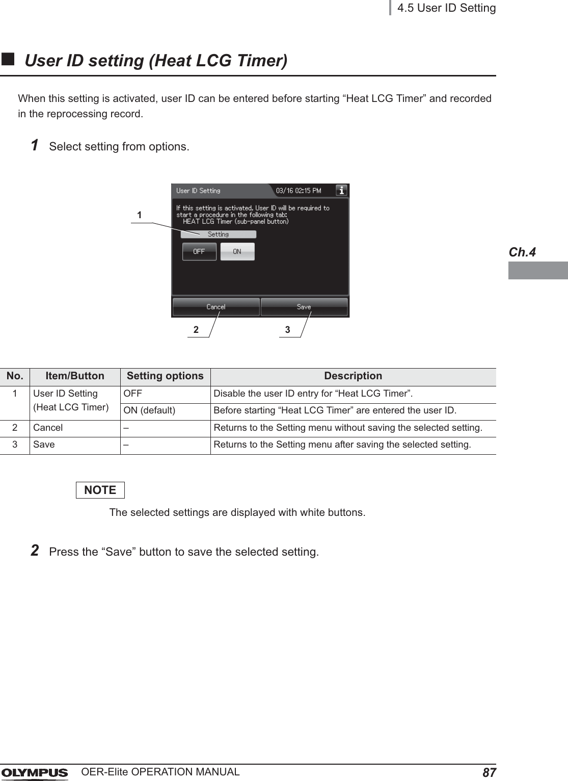
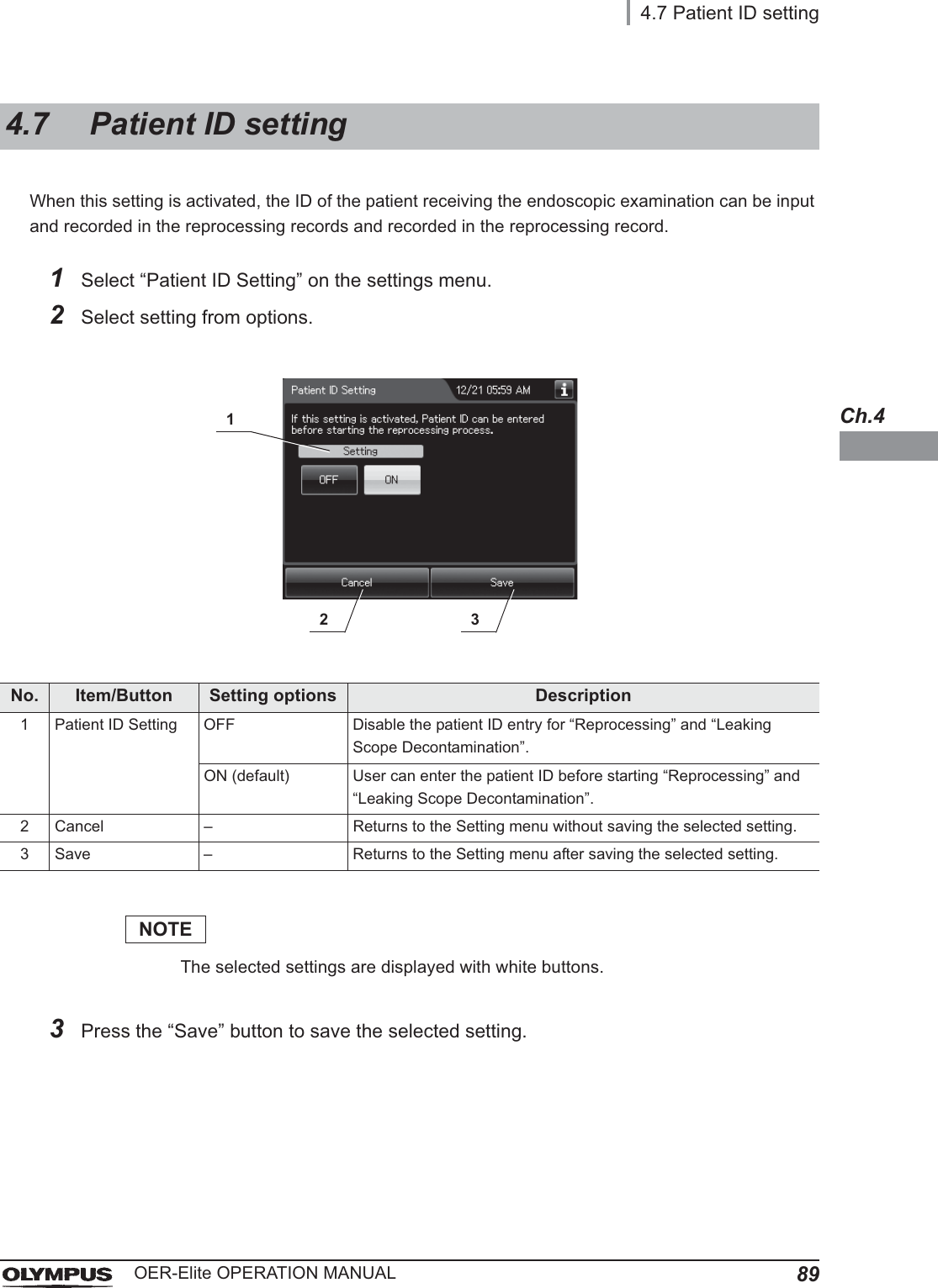
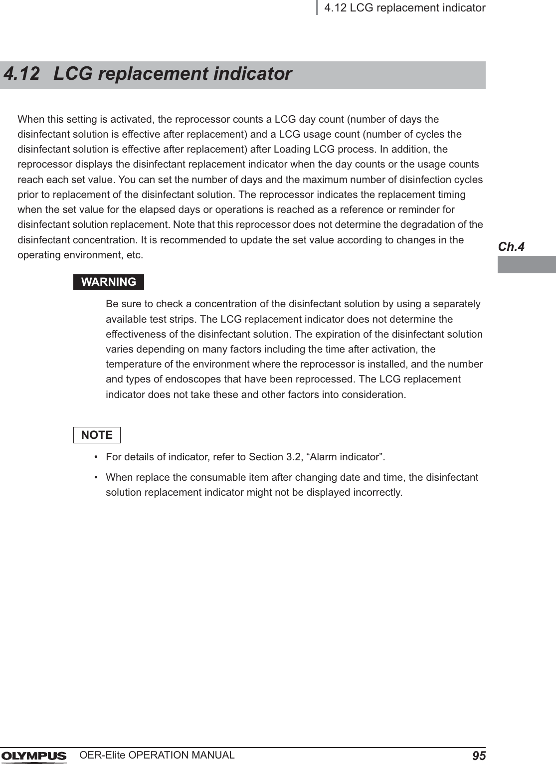
![1084.17 Print optionOER-Elite OPERATION MANUALCh.4Auto Print SettingIf this setting is activated, Reprocessing result and Leak Testing result will print automatically after the process is complete.NOTE• To print a record, an optional MAJ-2144 printer set is necessary.• If the printer is not connected to the reprocessor although “Auto Print” is selected, [E094] error occurs at the completion of reprocessing process, leak test, and leaking scope decontamination.1Select “Auto Print” on the Print option menu.2Select setting from options.No. Item/Button Setting options Description1 Auto Print Setting OFF (default) Disable the auto printing for “Reprocessing”.ON Enable the auto printing for “Reprocessing”.2 Cancel – Returns to the previous screen without saving the selected setting.3 Save – Returns to the previous screen after saving the selected setting.NOTEThe selected settings are displayed with white buttons.3Press the “Save” button to save the selected setting.12 3](https://usermanual.wiki/Olympus-Medical-Systems/RU2020.Operation-Manual-1/User-Guide-3575657-Page-118.png)