Olympus Medical Systems RU2020 Endoscope Reprocessor User Manual GT9883 0004 fm10
Olympus Medical Systems Corp. Endoscope Reprocessor GT9883 0004 fm10
UserManual.wiki
>
Olympus Medical Systems
>
RU2020 User Manual
>
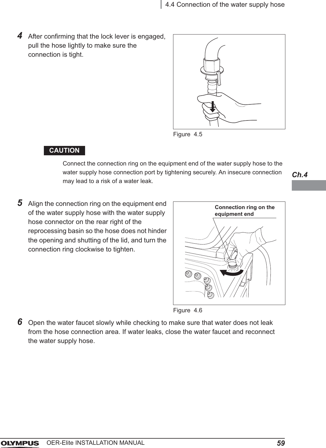
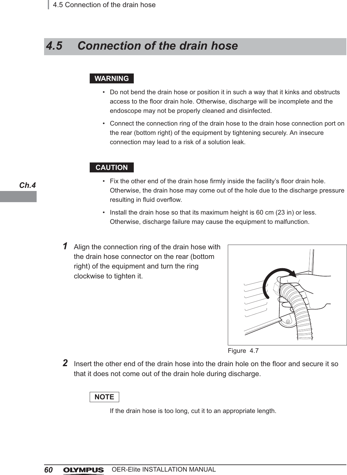
Installation Manual 1
Contents
1.
Operation Manual 1
2.
Operation Manual 2
3.
Operation Manual 3
4.
Operation Manual 4
5.
Operation Manual 5
6.
Installation Manual 1
7.
Installation Manual 2
Installation Manual 1
Navigation menu
Upload a User Manual
Namespaces
Wiki Guide
HTML
PDF
Info
Views
User Manual
Discussion / Help
Navigation
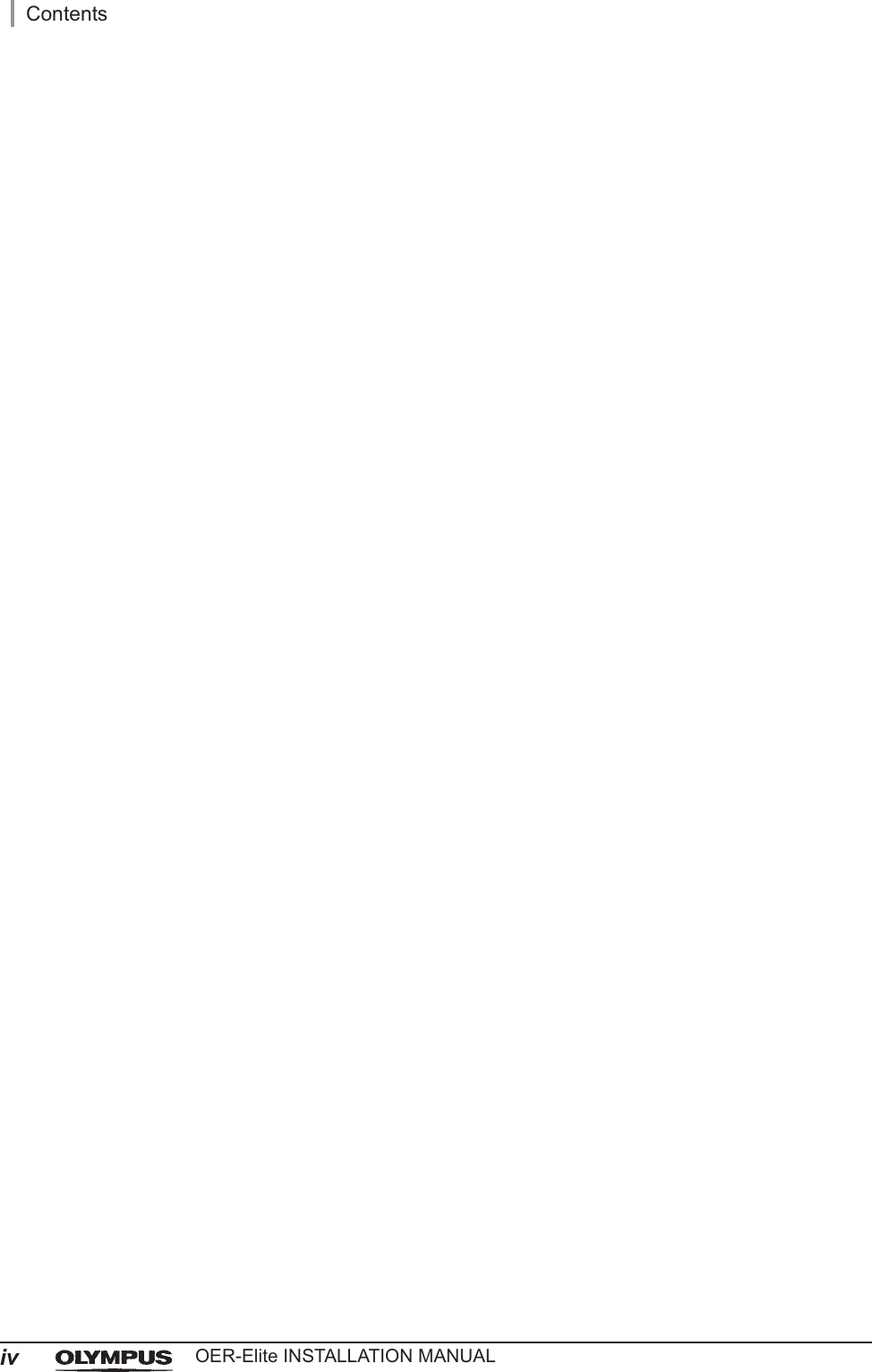
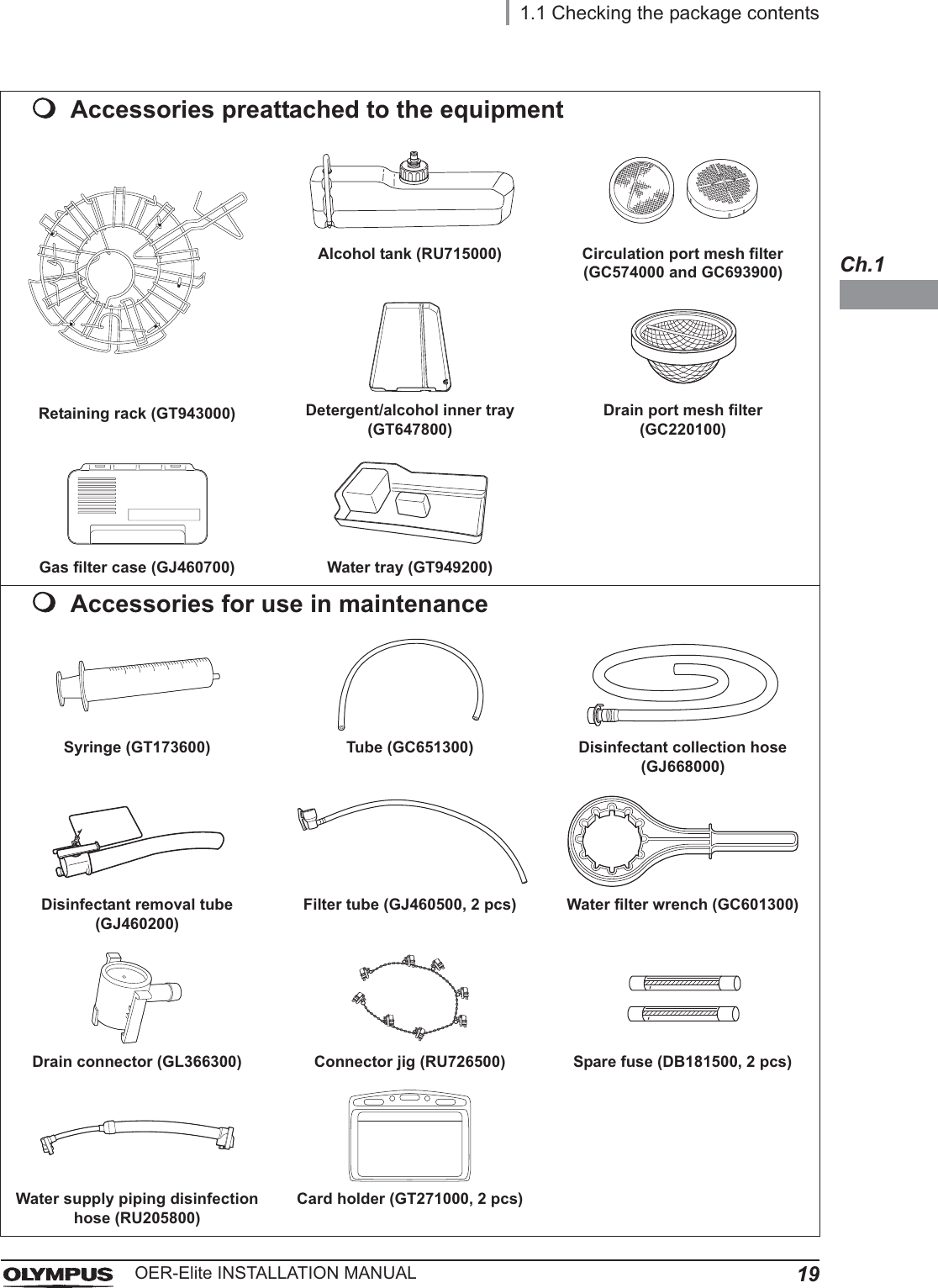
![Important Information — Please Read Before Use9OER-Elite INSTALLATION MANUALDetergentOlympus-validated detergent. Refer to Section 2.8, “Consumable accessories (Optional)” for details.Disinfectant solutionOlympus-validated disinfectant solution. Refer to Section 2.8, “Consumable accessories (Optional)” for details.Disinfection processA series of operations programmed into the equipment that enable it to perform disinfection of endoscopes.Error codeA code consisting of [E] and a three-digit number. This code is displayed on the touch screen if there is a problem with the equipment. When an error code is displayed, check the troubleshooting guide.LCGStands for Liquid Chemical Germicide. It refers to disinfectant solution displayed on GUI.Leak testA test to confirm that an endoscope is free of leaks. This equipment is capable of both the auto leak test and the manual leak test.Manual cleaningCleaning of an endoscope by hand.Modified precleaning and manual cleaningA precleaning and manual cleaning method that simplified due to subsequent use of the OER-Elite which automates cleaning steps in the process.MRCStands for Minimum Recommended Concentration.Patient IDIdentify information specific to each patient. It can be recorded in the histories of reprocessing, etc. For the patient ID input method, refer to Section 3.6, “Entering ID” in “Instructions-Operation manual”.Physician IDIdentity information specific to each endoscopist. It can be recorded in the histories of reprocessing, etc. For the physician ID input method, refer to Section 3.6, “Entering ID” in “Instructions-Operation manual”.](https://usermanual.wiki/Olympus-Medical-Systems/RU2020.Installation-Manual-1/User-Guide-3575694-Page-15.png)
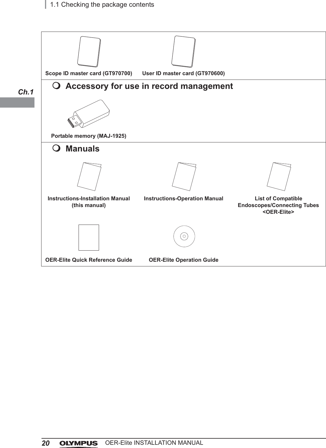
![10Important Information — Please Read Before UseOER-Elite INSTALLATION MANUALPortable memoryA digital medium for storage.PrecleaningCleaning of an endoscope performed after each procedure at the bedside of the endoscopy room.Procedure IDIdentify information specific to each procedure of the patient. It can be recorded in the histories of reprocessing, etc. For the procedure ID input method, refer to Section 3.6, “Entering ID” in “Instructions-Operation manual”.ProcessGeneric term for any operation, including cleaning and disinfection that is performed automatically by this equipment.Reprocessing processA series of operations for ultrasonic cleaning, detergent cleaning, disinfection, rinse, air purge, and alcohol flush of the outer surface or channels of endoscopes that run in a specified sequence and for a specified time. Reprocessing programs [1] to [4] can be selected by the user. Programs [1] to [4] have a fixed cleaning process time and disinfection process time. They also have different patterns of auto leak test and channel monitoring respectively.Scope IDIdentity information specific to each endoscope. It can be recorded in the histories of reprocessing, etc. For the scope ID input method, refer to Section 3.6, “Entering ID” in “Instructions-Operation manual”.Shelf lifeThe date of expiration of the effectiveness of a detergent or disinfectant before it is opened.Test stripDevice used to test if the concentration of disinfectant solution is effective for disinfection. Refer to Section 2.8, “Consumable accessories (Optional)” for details. (i.e., the minimum recommended concentration (MRC) specified by the disinfectant manufacturer)User IDIdentity information specific to each reprocessing operator. It can be recorded in the histories of reprocessing, etc. For the user ID input method, refer to Section 3.6, “Entering ID” in “Instructions-Operation manual”.](https://usermanual.wiki/Olympus-Medical-Systems/RU2020.Installation-Manual-1/User-Guide-3575694-Page-16.png)
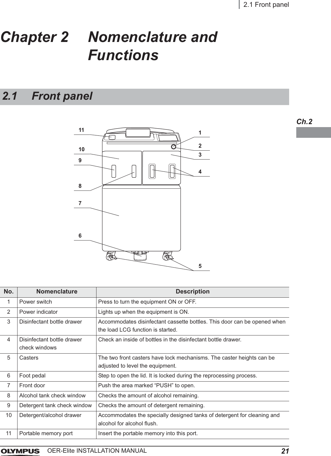
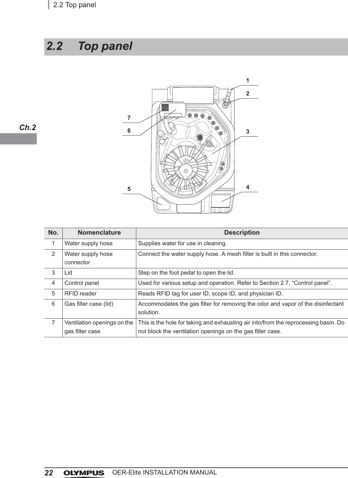
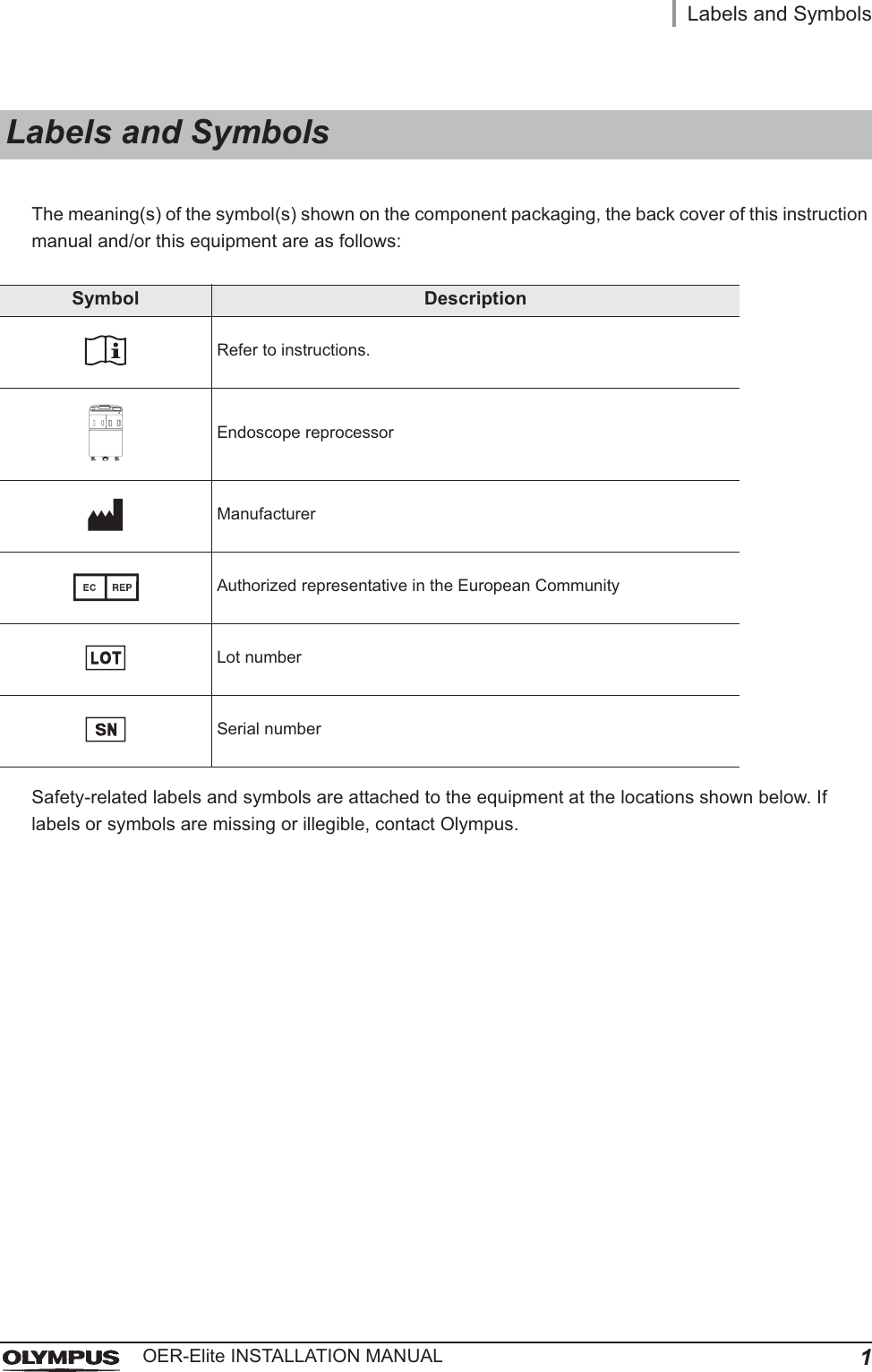
![14Outline of FunctionsOER-Elite INSTALLATION MANUALFollowing functions are available in this device.ReprocessingA series of operations that enable the equipment to perform ultrasonic cleaning, detergent cleaning, disinfection, rinse, air purge, and alcohol flush. A series of operations for ultrasonic cleaning, detergent cleaning, disinfection, rinse, air purge, and alcohol flush of the outer surface and channels of endoscopes in a specified sequence and for a specified time. Reprocessing programs [1] to [4] can be selected by the user. Programs [1] to [4] have a fixed cleaning process time and disinfection process time. They also have different patterns of auto leak test and channel monitoring respectively. For details, refer to Chapter 6, “Reprocessing Operations” in “Instructions-Operation manual”.Drain LCGThis function drains the disinfectant solution from the disinfectant tank. For details, refer to Section 8.2, “Replacing the disinfectant solution” in “Instructions-Operation manual”.Load LCGThis function loads the disinfectant solution by setting a new disinfectant bottle. For details, refer to Section 8.2, “Replacing the disinfectant solution” in “Instructions-Operation manual”.Heat LCGA process for heating disinfectant solution until it reaches the specified temperature. This process is performed automatically during the reprocessing program. It can also be performed as an independent operation. For details, refer to Section 7.2, “Heat LCG” in “Instructions-Operation manual”.Heat LCG TimerThe function for heating the disinfectant solution until the specified temperature by the specified time. For details, refer to Section 7.3, “Heat LCG Timer” in “Instructions-Operation manual”.Mix LCGThis function is mixing the disinfectant solution to the appropriate concentration concentration and enables accurate concentration check.Outline of Functions](https://usermanual.wiki/Olympus-Medical-Systems/RU2020.Installation-Manual-1/User-Guide-3575694-Page-20.png)