Olympus Medical Systems RU5808 WIRELESS RECEIVER User Manual XGT8045 0001 fm10
Olympus Medical Systems Corp. WIRELESS RECEIVER XGT8045 0001 fm10
User Manual
INSTRUCTIONS
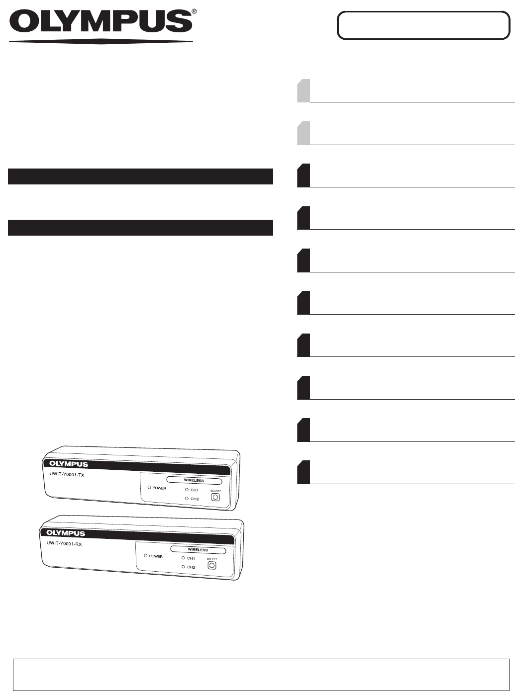
WIRELESS TRANSMITTER
UWIT-Y0001-TX
WIRELESS RECEIVER
UWIT-Y0001-RX
Labels and Symbols 1
Important Information — Please Read Before
Use 4
Chapter 1 Checking the Package Contents 11
Chapter 2 Nomenclature and Functions 15
Chapter 3 Installation and Connection 21
Chapter 4 Inspection 31
Chapter 5 Operation 35
Chapter 6 Care, Storage, and Disposal 37
Chapter 7 Troubleshooting 39
Appendix 43
USA: CAUTION: Federal law restricts this device to sale by or on the order of a physician.
OPERATION MANUAL

Contents
i
UWIT-Y0001-TX, UWIT-Y0001-RX INSTRUCTION MANUAL
Contents
Labels and Symbols .......................................................................................................... 1
Important Information — Please Read Before Use ......................................................... 4
Intended use .......................................................................................................................... 4
Instruction manual ................................................................................................................. 4
User qualifications ................................................................................................................. 5
Instrument compatibility ......................................................................................................... 5
Repair and modification ......................................................................................................... 5
Signal words .......................................................................................................................... 6
Dangers, warnings, and cautions .......................................................................................... 6
EMC (Electromagnetic Compatibility) .............................................................................. 8
Summary of Equipment Functions .................................................................................. 9
Transmitting function of HDTV video signal over radio frequency channel ........................... 9
Pair changing function ........................................................................................................... 9
Chapter 1 Checking the Package Contents ....................................... 11
1.1 Checking the package contents ............................................................................ 11
Chapter 2 Nomenclature and Functions ............................................ 15
2.1 Symbols and descriptions ..................................................................................... 15
2.2 Front panel of Wireless Transmitter ..................................................................... 16
2.3 Rear panel of Wireless Transmitter ...................................................................... 17
2.4 Front panel of Wireless Receiver .......................................................................... 18
2.5 Rear panel of Wireless Receiver ........................................................................... 18
2.6 AC adapter .............................................................................................................. 19
Chapter 3 Installation and Connection ............................................... 21
3.1 Precautions for installation and connection ........................................................ 21
3.2 Installation of the equipment ................................................................................. 22
3.3 Installation of the AC adaptor ............................................................................... 24
Installation on the Attachment for UWIT (MAJ-Y0149) ........................................................ 24
3.4 Connecting AC adaptor to Wireless Transmitter or Receiver ............................ 25
3.5 Connecting AC adaptor to an AC mains power supply ...................................... 26
When using the power cord of mobile workstation (WM-NP1, WM-WP1, WM-DP1) .......... 26
When using the supplied AC cord ....................................................................................... 26
3.6 Connecting video cables to Wireless Transmitter .............................................. 27
Selection of video input terminal .......................................................................................... 27
Connection diagram (When using HD-SDI) ......................................................................... 28
Connection diagram (When using DVI) ............................................................................... 29

ii
Contents
UWIT-Y0001-TX, UWIT-Y0001-RX INSTRUCTION MANUAL
3.7 Connecting video cables to Wireless Receiver ................................................... 30
Connection diagram ............................................................................................................ 30
Chapter 4 Inspection ............................................................................ 31
4.1 Inspection of the power supply ............................................................................. 31
4.2 Inspection of the displayed image ........................................................................ 32
Chapter 5 Operation ............................................................................. 35
5.1 Turn the Wireless Transmitter and Receiver ON ................................................. 35
When the mobile workstation (WM-NP1, WM-WP1, WM-DP1) is used .............................. 35
When the mobile workstation (WM-NP1, WM-WP1, WM-DP1) is not used ........................ 35
5.2 Connection of the Wireless Transmitter and Receiver ....................................... 36
Chapter 6 Care, Storage, and Disposal .............................................. 37
6.1 Care .......................................................................................................................... 37
6.2 Storage .................................................................................................................... 38
6.3 Disposal ................................................................................................................... 38
Chapter 7 Troubleshooting .................................................................. 39
7.1 Troubleshooting ..................................................................................................... 39
7.2 Troubleshooting guide ........................................................................................... 40
7.3 Returning the Wireless Image Transmitter Unit for repair .................................. 42
Appendix ................................................................................................. 43
Combination equipment .................................................................................................. 43
System chart ........................................................................................................................ 43
FCC (for Wireless Transmitter and Receiver) ................................................................ 45
FCC/IC (for Wireless Transmitter and Receiver) ........................................................... 45
Specifications ................................................................................................................... 46
Environment ........................................................................................................................ 46
Specifications ....................................................................................................................... 48
EMC information .............................................................................................................. 50
FCC WARNING ................................................................................................................. 54
Labels and Symbols
1
UWIT-Y0001-TX, UWIT-Y0001-RX INSTRUCTION MANUAL
Safety-related labels and symbols are attached on the locations shown below. If labels or symbols are
missing or illegible, contact Olympus.
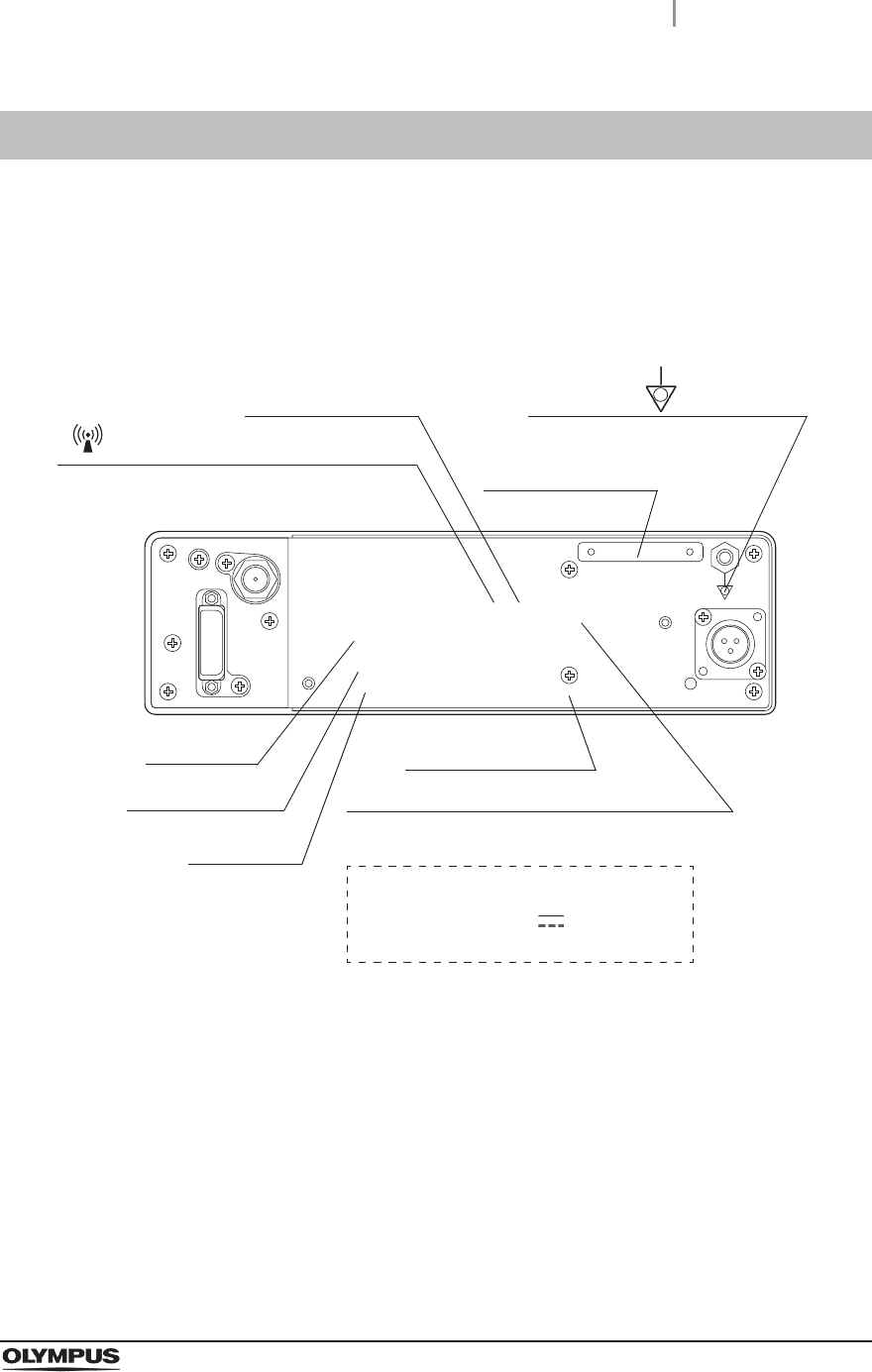
Wireless Transmitter
Labels and Symbols
Serial number plate
This instrument emits RF (Radio Frequency)
energy to perform intended functions.
Manufacturer name
Potential equalization terminal
CSA/UL marking
Electric rating
The product name, rated voltage, and
notice for AC adapter are shown
WIRELESS TRANSMITTER
MODEL :UWIT-Y0001-TX
POWER INPUT : 12 V 1 A
For use with power supply OLP-K027-M
FCC note
FCC ID number
IC number
2
Labels and Symbols
UWIT-Y0001-TX, UWIT-Y0001-RX INSTRUCTION MANUAL
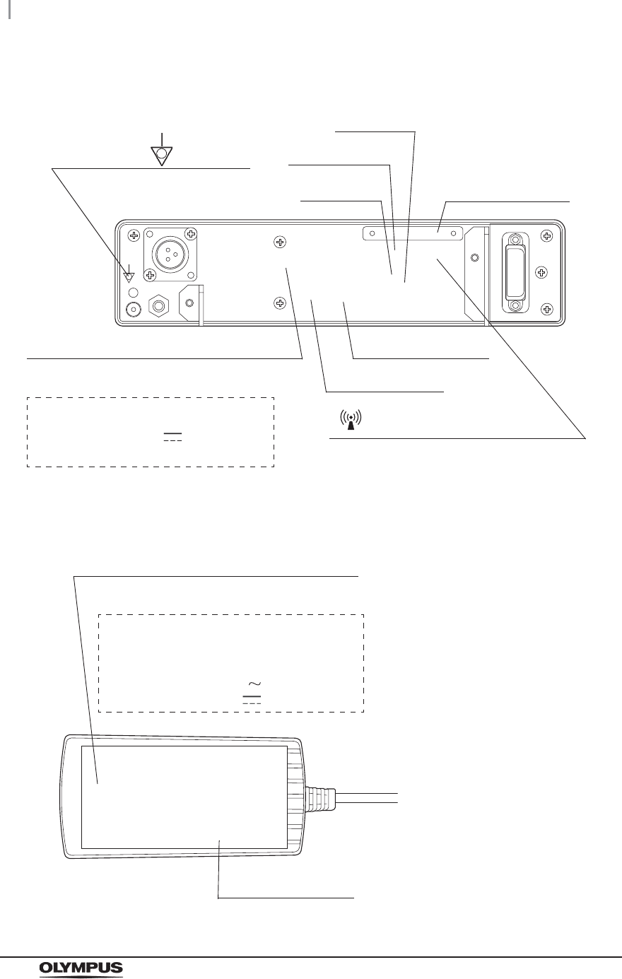
Wireless Receiver
AC Adaptor
Serial number plate
Manufacturer name
Potential equalization terminal
CSA/UL marking
Electric rating
The product name, rated voltage, and
notice for AC adapter are shown
WIRELESS RECEIVER
MODEL :UWIT-Y0001-RX
POWER INPUT : 12 V 0.8 A
For use with power supply OLP-K027-M
FCC note
FCC ID number
IC number
This instrument emits RF (Radio Frequency)
energy to perform intended functions.
OLYMPUS
AC Adapter
Model Name: OLP-K027-M
INPUT : 100–240 V 1–0.5 A, 50/60 Hz
OUTPUT : 12 V 1.3 A
Manufacturer name
Electric rating
The product name, rated voltage, and
notice for AC adapter are shown

Labels and Symbols
3
UWIT-Y0001-TX, UWIT-Y0001-RX INSTRUCTION MANUAL
Back cover of this instruction manual
Symbol Description
Manufacturer
Authorized representative in the European Community

4
Important Information — Please Read Before Use
UWIT-Y0001-TX, UWIT-Y0001-RX INSTRUCTION MANUAL
Intended use
The Olympus Wireless Image Transmitter Unit UWIT-Y0001 is a paired transmitter and receiver,
intended for delivery of video signals over a radio-frequency link to a video display during endoscopic
and general surgical procedures. The Olympus UWIT-Y0001 is a non-sterile reusable device not
intended for use in the sterile field. It is intended for use by qualified physicians having complete
knowledge of these surgical procedures.
Instruction manual
This instruction manual contains essential information on using this Wireless Image Transmitter Unit
safely and effectively. Before use, thoroughly review this manual and the manuals of all equipment
which will be used during the procedure and use the equipment as instructed.
Keep this and all related instruction manuals in a safe, accessible location. If you have any questions
or comments about any information in this manual, please contact Olympus.
Terms used in this manual
Video system center:
The video system center is a device that converts signals from a videoscope or video
converter, camera head into monitor images.
Wall mains outlet:
The wall mains outlet is a wall AC mains power outlet socket having the exclusive terminal
for grounding.
Important Information — Please Read Before Use

Important Information — Please Read Before Use
5
UWIT-Y0001-TX, UWIT-Y0001-RX INSTRUCTION MANUAL
User qualifications
If there is an official standard on user qualifications to perform endoscopy and endoscopic treatment
that is defined by the medical administration or other official institutions, such as academic societies on
endoscopy, follow that standard. If there is no official qualification standard, the operator of this
instrument must be a physician approved by the medical safety manager of the hospital or person in
charge of the department (department of internal medicine, etc.). The physician should be capable of
safely performing the planned endoscopy and endoscopic treatment following guidelines set by the
academic societies on endoscopy, etc., and considering the difficulty of endoscopy and endoscopic
treatment. This manual does not explain or discuss endoscopic procedures.
Instrument compatibility
Refer to the “System chart” on page 43 to confirm that this Wireless Image Transmitter Unit is
compatible with the ancillary equipment being used. Using incompatible equipment can result in
patient injury or equipment damage and makes it impossible to obtain the expected functionality.
This instrument complies with the EMC standard for medical electrical equipment; edition 3
(IEC 60601-1-2: 2007), edition 2 (IEC 60601-1-2: 2001). However, when connected with an instrument
that complies with the EMC standard for medical electrical equipment; edition 1 (IEC 60601-1-2: 1993),
the whole system complies with edition 1.
Repair and modification
This Wireless Image Transmitter Unit does not contain any user-serviceable parts. Do not
disassemble, modify or attempt to repair it; patient or operator injury, equipment damage and/or the
impossibility to obtain the expected functionality can result. Some problems that appear to be
malfunctions may be correctable by referring to Chapter 7, “Troubleshooting”. If the problem cannot be
resolved using the information in Chapter 7, contact Olympus. This instrument is to be repaired by
Olympus technicians only.
Change or modifications not expressly approved by the party responsible for compliance could void
the user’s authority to operate the equipment.
All interface cables used to connect peripherals must be shielded in order to comply with the limits for
a digital device pursuant to Subpart B of Part 15 of FCC Rules.

6
Important Information — Please Read Before Use
UWIT-Y0001-TX, UWIT-Y0001-RX INSTRUCTION MANUAL
Signal words
The following signal words are used throughout this manual:
Dangers, warnings, and cautions
Follow the dangers, warnings and cautions given below when handling this Wireless Image
Transmitter Unit. This information is to be supplemented by the dangers, warnings, and cautions given
in each chapter.
DANGER
• Strictly observe the following precautions. Failure to do so may place the patient
and medical personnel in danger of electric shock.
Keep fluids away from all electrical equipment. If fluids are spilled on or into the
unit, stop operation of the Wireless Image Transmitter Unit immediately and
contact Olympus.
Do not prepare, inspect or use this Wireless Image Transmitter Unit with wet
hands.
• Never install and operate the Wireless Image Transmitter Unit in locations where:
The concentration of oxygen is high;
Oxidizing agents (such as nitrous oxide (N2O)) are present in the atmosphere;
Flammable gases are present in the atmosphere;
Flammable liquids are near.
Otherwise, explosion or fire may result because this Wireless Image Transmitter
Unit is not explosion-proof.
Indicates an imminently hazardous situation which, if not avoided, will result in
death or serious injury.
Indicates a potentially hazardous situation which, if not avoided, could result in
death or serious injury.
Indicates a potentially hazardous situation which, if not avoided, may result in minor
or moderate injury. It may also be used to alert against unsafe practices or potential
equipment damage.
Indicates additional helpful information.
DANGER
WARNING
CAUTION
NOTE

Important Information — Please Read Before Use
7
UWIT-Y0001-TX, UWIT-Y0001-RX INSTRUCTION MANUAL
WARNING
• In case of Wireless Image Transmitter Unit failure or malfunction, always keep
another Wireless Image Transmitter Unit in the room ready for use.
• Only use the supplied AC adaptor. Do not use the supplied AC adaptor to power
other devices. The equipment may fail or the power cord may burn.
• Always use the power cord and connection cables that were shipped with the
monitor or mobile workstation. Using other power cords or connection cables may
result in an electric shock or malfunction.
CAUTION
• Do not use a pointed or hard object to press the buttons on the front panel. This
may damage the buttons.
• Do not touch the electrical contacts inside the Wireless Image Transmitter Unit’s
connectors.
• Do not apply excessive force to this Wireless Image Transmitter Unit and/or other
instruments connected. Otherwise, damage and/or malfunction can occur.

8
EMC (Electromagnetic Compatibility)
UWIT-Y0001-TX, UWIT-Y0001-RX INSTRUCTION MANUAL
• In order to provide the intended functionality (HDTV image transmission), the Wireless Image
Transmitter Unit (UWIT-Y0001) emits RF (Radio Frequency) energy while in operation. This
may affect electrical devices in the vicinity.
• The Wireless Image Transmitter Unit (UWIT-Y0001) utilizes RF signals shown below.
Accordingly, it is subject to electromagnetic interference from other in-band equipment in the
vicinity.
EMC (Electromagnetic Compatibility)
Central Frequency 60.48 GHz (When using CH1)
62.64 GHz (When using CH2)
Frequency range of
possible interference
59.40 – 61.56 GHz (When using CH1)
61.56 – 63.72 GHz (When using CH2)
Modulation method OFDM
High-frequency
output
Less than +40 dBm

Summary of Equipment Functions
9
UWIT-Y0001-TX, UWIT-Y0001-RX INSTRUCTION MANUAL
This Wireless Image Transmitter Unit transmit HDTV video signal over radio frequency channel with no
compression and low latency between a pair of transmitter and receiver. This instrument supports
functions below.
Transmitting function of HDTV video signal over radio
frequency channel
• When using the HD-SDI input connector for the Wireless Transmitter
A paired Wireless Transmitter and Receiver can transmit 1080i (60/50 Hz) digital HDTV
video signal over radio frequency channel
• When using the DVI input connector for the Wireless Receiver
A paired Wireless Transmitter and Receiver can transmit 1080p (60/50 Hz) digital HDTV
video signal and SXGA: 1280 × 1024 (60 Hz) digital video signal over radio frequency
channel
Pair changing function
By using the SELECT button of the Wireless Transmitter and Receiver, the Channel (CH1 or CH2) for
pairing Transmitter and Receiver can be set manually.
oSee Section 5.2, “Connection of the Wireless Transmitter and Receiver”.
Summary of Equipment Functions

10
Summary of Equipment Functions
UWIT-Y0001-TX, UWIT-Y0001-RX INSTRUCTION MANUAL
1.1 Checking the package contents
11
UWIT-Y0001-TX, UWIT-Y0001-RX INSTRUCTION MANUAL
Ch.1
Chapter 1 Checking the Package
Contents
Match all items in the package with the components shown below. Inspect each item for damage. If the
Wireless Image Transmitter Unit is damaged, a component is missing, or you have any questions, do
not use the Wireless Image Transmitter Unit; immediately contact Olympus.
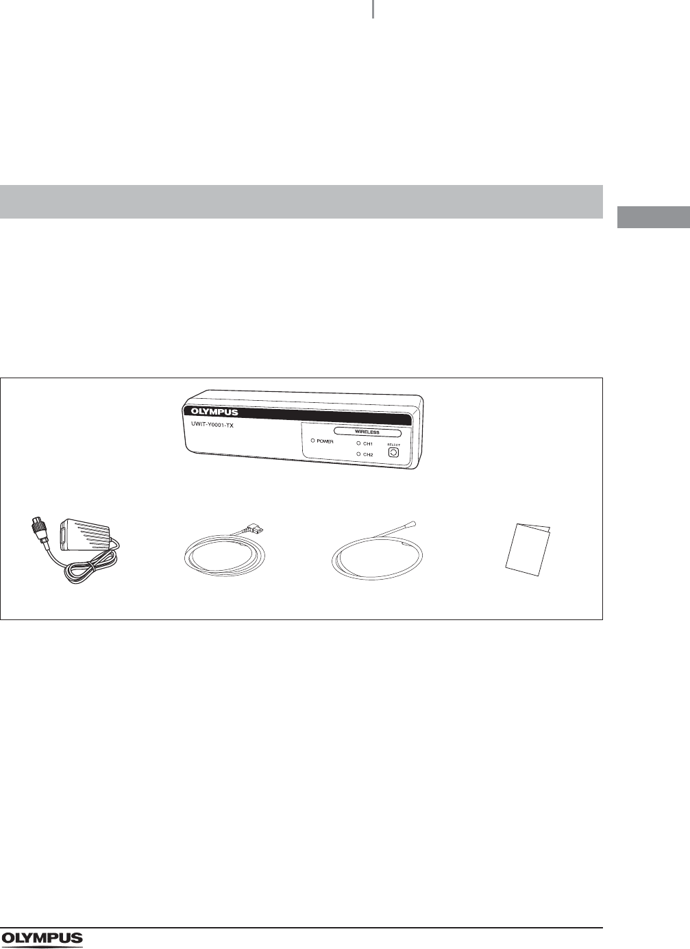
Wireless Transmitter
1.1 Checking the package contents
Wireless Transmitter (UWIT-Y0001-TX)
AC adaptor AC cord SDI cable Instruction manual
12
1.1 Checking the package contents
UWIT-Y0001-TX, UWIT-Y0001-RX INSTRUCTION MANUAL
Ch.1
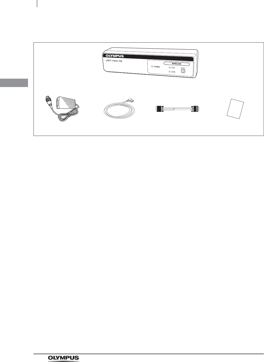
Wireless Receiver
Wireless Receiver (UWIT-Y0001-RX)
AC adaptor AC cord DVI cable (MAJ-1945) Access sheet
1.1 Checking the package contents
13
UWIT-Y0001-TX, UWIT-Y0001-RX INSTRUCTION MANUAL
Ch.1
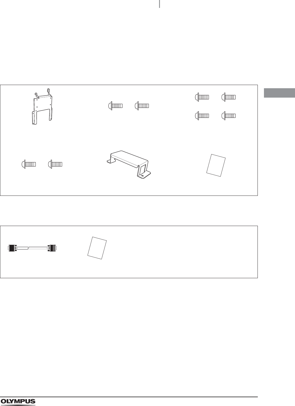
Optional equipment
The following products are optional Olympus products that may be purchased separately.
Attachment for UWIT (MAJ-Y0149)
DVI cable (MAJ-1945)
Attachment for UWIT
(MAJ-Y0149)
Screw (for installing UWIT-Y0001-TX
or UWIT-Y0001-RX) (2 pcs.)
Screw (for installing OEV261H)
(4 pcs.)
Screw (for AC adaptor) (2 pcs.) Attachment for AC adaptor Access sheet
DVI cable (MAJ-1945) Access sheet

14
1.1 Checking the package contents
UWIT-Y0001-TX, UWIT-Y0001-RX INSTRUCTION MANUAL
Ch.1
2.1 Symbols and descriptions
15
UWIT-Y0001-TX, UWIT-Y0001-RX INSTRUCTION MANUAL
Ch.2
Chapter 2 Nomenclature and
Functions
The instrument nomenclature, functions, and specifications are described in this chapter.
Front panel
Rear panel
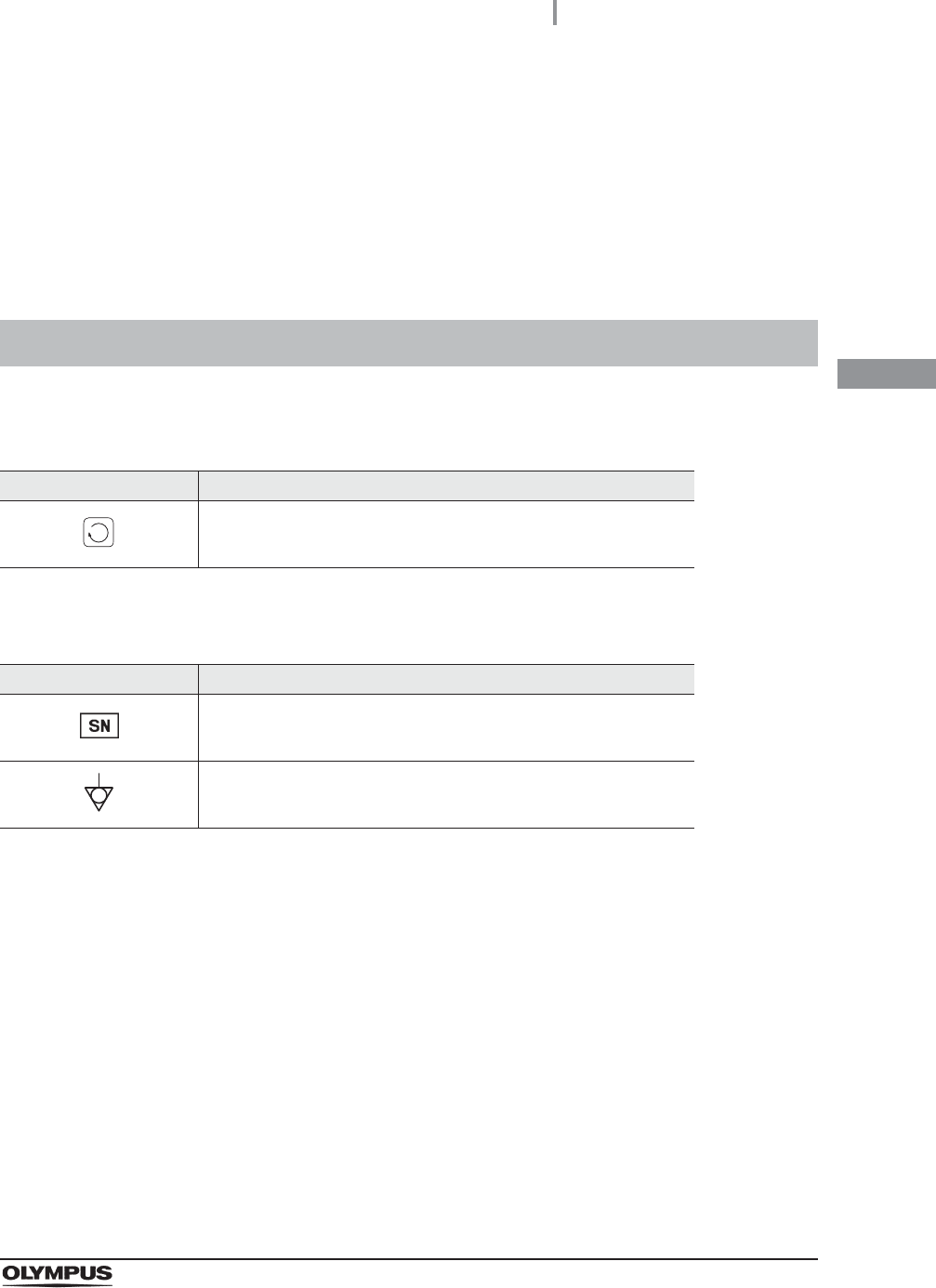
2.1 Symbols and descriptions
Symbol Description
Select
Symbol Description
Serial number
Potential equalization terminal
16
2.2 Front panel of Wireless Transmitter
UWIT-Y0001-TX, UWIT-Y0001-RX INSTRUCTION MANUAL
Ch.2
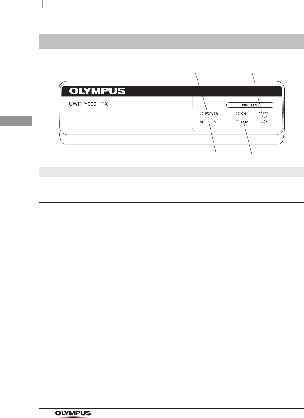
2.2 Front panel of Wireless Transmitter
No. Nomenclature Description
1 Power indicator Lights up when the Wireless Transmitter is ON.
2 SELECT button When pressed and held for 1 second, the SELECT button switches between the CH1
and CH2 Channels.
3 Channel Status
display
The selected Channel (CH1 or CH2) will have a steady light or blink. It blinks while
searching to connect to the Wireless Receiver. It will have a steady light when
connection has been established.
4 Video selection
status display
Selected video input selection (SDI or DVI) will have a steady light or blink. It will have a
steady light when the Wireless Transmitter detects supported video format, and it will
blink when the Wireless Transmitter cannot detect any video signal or unsupported
video format is detected.
2
3
4
1
2.3 Rear panel of Wireless Transmitter
17
UWIT-Y0001-TX, UWIT-Y0001-RX INSTRUCTION MANUAL
Ch.2
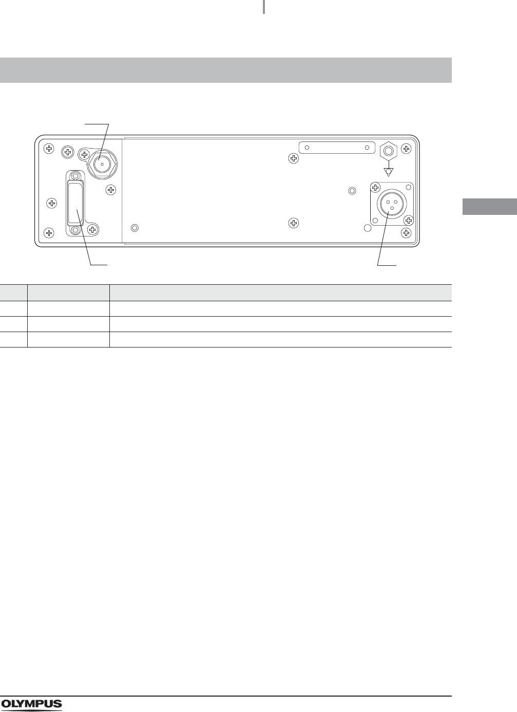
2.3 Rear panel of Wireless Transmitter
No. Nomenclature Description
1 HD-SDI IN terminal Inputs HD-SDI video signal.
2 DC IN terminal This is the 12V DC input terminal. Connect the supplied AC adaptor to this terminal.
3 DVI IN terminal Inputs digital video signal.
2
3
1
18
2.4 Front panel of Wireless Receiver
UWIT-Y0001-TX, UWIT-Y0001-RX INSTRUCTION MANUAL
Ch.2
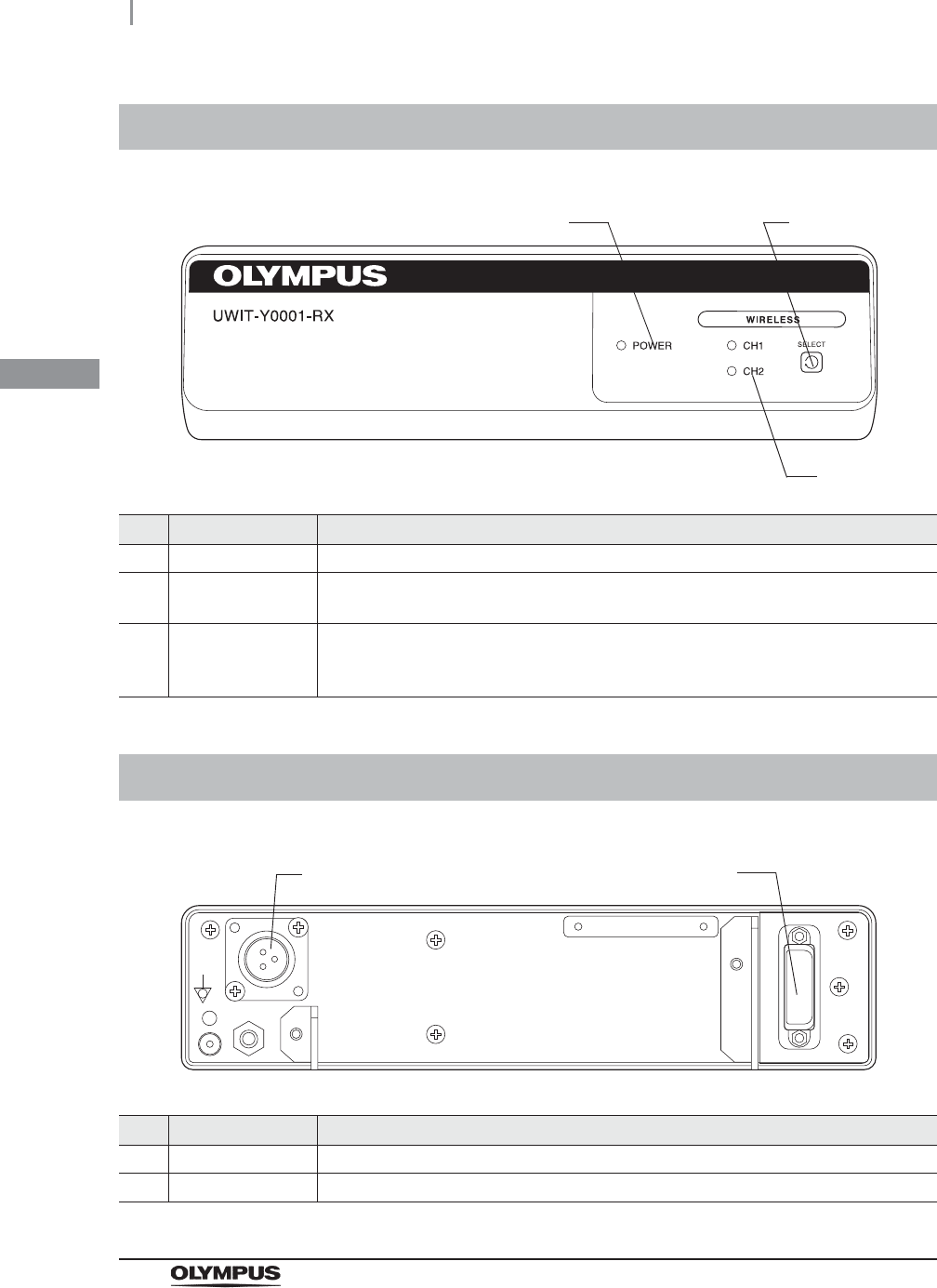
2.4 Front panel of Wireless Receiver
No. Nomenclature Description
1 Power indicator Lights up when the Wireless Receiver is ON.
2 SELECT button When pressed and held for 1 second, the SELECT button switches between the CH1
and CH2 Channels.
3 Channel Status
display
The selected Channel (CH1 or CH2) will have a steady light or blink. It blinks while
searching to connect to the Wireless Transmitter. It will have a steady light when
connection has been established.
2.5 Rear panel of Wireless Receiver
No. Nomenclature Description
1 DC IN terminal This is the 12V DC input terminal. Connect the supplied AC adaptor to this terminal.
2 DVI OUT terminal Outputs digital video signal.
2
3
1
12
2.6 AC adapter
19
UWIT-Y0001-TX, UWIT-Y0001-RX INSTRUCTION MANUAL
Ch.2
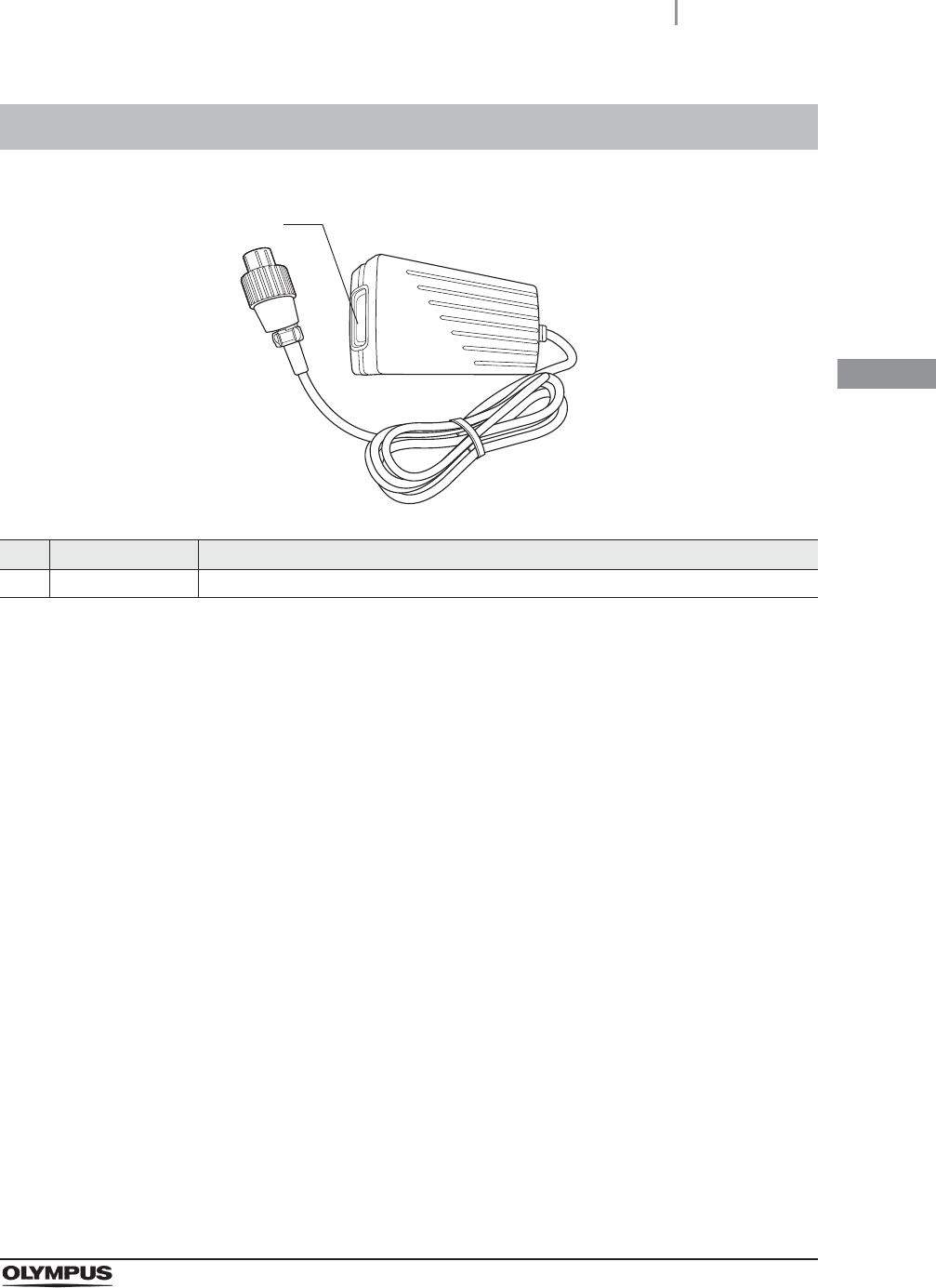
2.6 AC adapter
No. Nomenclature Description
1 AC IN terminal This is the AC input terminal.
1

20
2.6 AC adapter
UWIT-Y0001-TX, UWIT-Y0001-RX INSTRUCTION MANUAL
Ch.2

3.1 Precautions for installation and connection
21
UWIT-Y0001-TX, UWIT-Y0001-RX INSTRUCTION MANUAL
Ch.3
Chapter 3 Installation and Connection
Prepare this Wireless Image Transmitter Unit and compatible equipment (shown in the “System
chart” on page 43) before each use. Referring to the instruction manuals of each system component,
install and connect the equipment according to the procedure described in this chapter.
WARNING
Review this chapter thoroughly, and prepare the instruments properly before use. If
the equipment is not properly prepared before each use, equipment damage,
patient and operator injury and/or fire can occur.
CAUTION
• Use appropriate cables only. Otherwise, equipment damage or malfunction can
result.
• Properly and securely connect all cables. If the cable connector has a locking
mechanism, such as connection screws, lock the cable connector. Otherwise,
equipment damage or malfunction, such as no images on the monitor can result.
• The cables should not be sharply bent, pulled, twisted or crushed. Cable damage
can result.
• Use this instrument only under the conditions described in “Environment” on
page 46 and “Specifications” on page 48. Otherwise, improper performance,
compromised safety and/or equipment damage may result.
3.1 Precautions for installation and connection
22
3.2 Installation of the equipment
UWIT-Y0001-TX, UWIT-Y0001-RX INSTRUCTION MANUAL
Ch.3
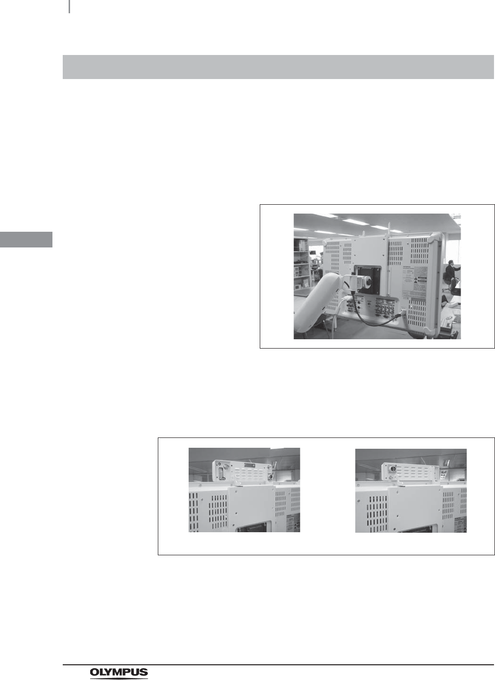
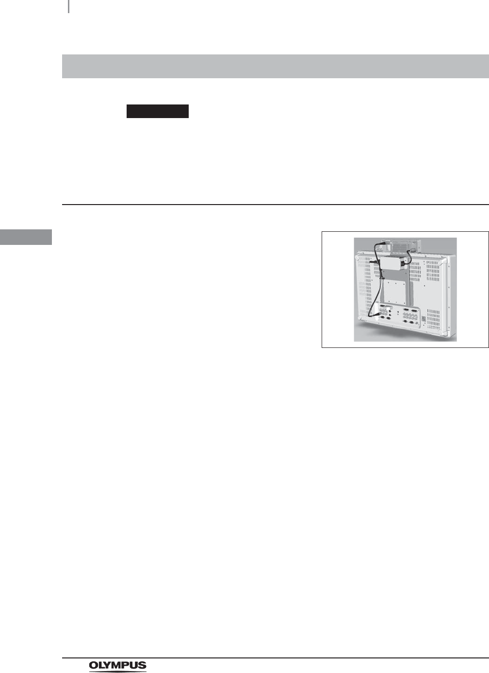
Use Attachment for UWIT (MAJ-Y0149) for installing the Wireless Transmitter or Receiver. Check the
unused mounting screw holes on the rear panel of OEV261H installed to LCD arm, and fix the Wireless
Transmitter or Receiver using supplied screws.
3.2 Installation of the equipment
1Check the rear panel of OEV261H installed to LCD arm, and align the unused
mounting screw holes of OEV261H with the mounting screw holes on the Attachment
for UWIT (MAJ-Y0149).
Figure 3.1
2Fix the Attachment for UWIT onto the top back of the high definition LCD monitor
OEV261H using the four screws provided with the Attachment for UWIT.
3Align the mounting screw holes on the rear of the Wireless Transmitter or Receiver
with the mounting screw holes on the Attachment for UWIT.
Figure 3.2
4Fix the Wireless Transmitter or Receiver onto the Attachment for UWIT using two
screws provide with the Attachment for UWIT.
UWIT-Y0001-TX UWIT-Y0001-RX

3.2 Installation of the equipment
23
UWIT-Y0001-TX, UWIT-Y0001-RX INSTRUCTION MANUAL
Ch.3
CAUTION
• Ensure that the Wireless Transmitter or Receiver is fixed firmly to the high definition
LCD monitor OEV261H. Otherwise, the Wireless Transmitter or Receiver may fall
and cause injury to the operator or damage the Wireless Transmitter or Receiver.
• Use a monitor mount with sufficient load resistance to support the combined weight
of the monitor and the Wireless Transmitter or Receiver. If the monitor with the
Wireless Transmitter or Receiver falls, patient or operator injury and/or equipment
damage may result.
• Do not use screws other than those provided with the Attachment for UWIT.
Otherwise, the Wireless Transmitter or Receiver cannot be fixed firmly to the
Attachment for UWIT and the Wireless Transmitter or Receiver may drop, causing
injury to the operator or damage the Wireless Transmitter or Receiver.
• Do not install the monitor on mobile workstations other than those listed in this
instruction manual. Otherwise, the mobile workstation may tip, injury to the operator
or damage of the monitor/equipment on the mobile workstation may result.
• When installing the Wireless Transmitter and Receiver to the high definition LCD
monitor OEV261H which is on the ceiling arm, ensure that there is no mechanical
interference with other moving part of the ceiling arm/pendant.
• Check if the unit is intended to install by referring to front or rear panel of the
Wireless Transmitter or Receiver before the installation.
24
3.3 Installation of the AC adaptor
UWIT-Y0001-TX, UWIT-Y0001-RX INSTRUCTION MANUAL
Ch.3
WARNING
Keep fluids away from the AC adaptor. Failure to do so may place the patient and
medical personnel in danger of an electric shock.
Installation on the Attachment for UWIT (MAJ-Y0149)
3.3 Installation of the AC adaptor
Fix the AC adaptor to the Attachment for UWIT
using the attachment for AC adapter provided
with the Attachment for UWIT.
Figure 3.3
3.4 Connecting AC adaptor to Wireless Transmitter or Receiver
25
UWIT-Y0001-TX, UWIT-Y0001-RX INSTRUCTION MANUAL
Ch.3
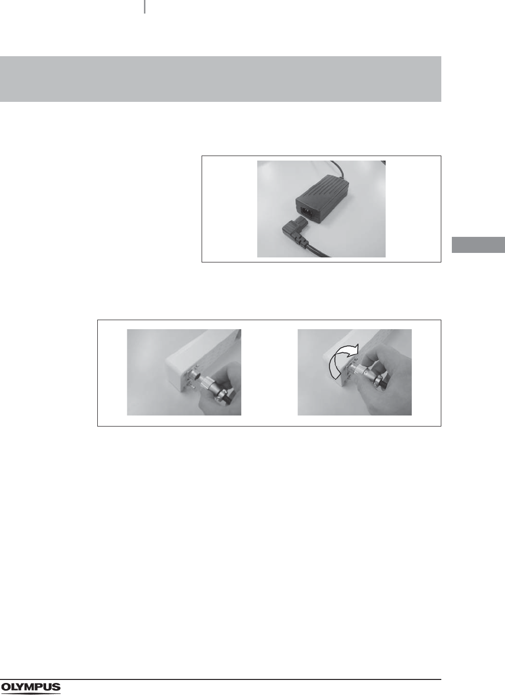
3.4 Connecting AC adaptor to Wireless Transmitter
or Receiver
1Connect the power cord to the AC IN terminal on the AC adaptor.
Figure 3.4
2Insert the DC cord into the DC IN terminal on the Wireless Transmitter or Receiver.
Fix DC cord by winding finger screw.
Figure 3.5
26
3.5 Connecting AC adaptor to an AC mains power supply
UWIT-Y0001-TX, UWIT-Y0001-RX INSTRUCTION MANUAL
Ch.3
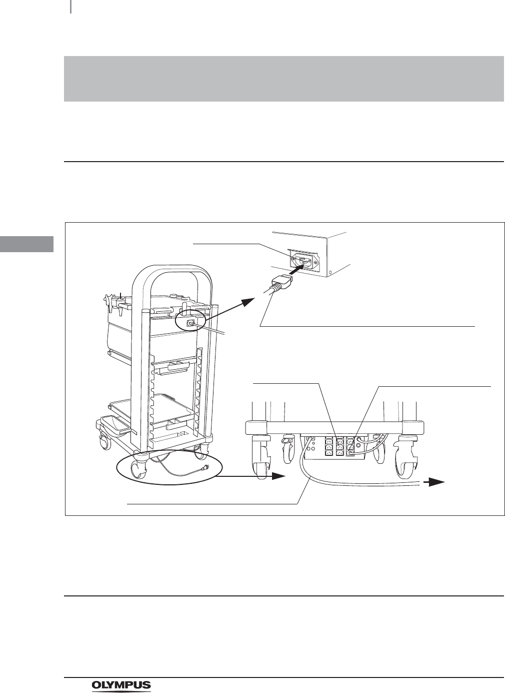
When using the power cord of mobile workstation
(WM-NP1, WM-WP1, WM-DP1)
When using the supplied AC cord
3.5 Connecting AC adaptor to an AC mains power
supply
1Connect the power cord provided with the mobile workstation to AC IN terminal of AC
adaptor and to the power socket of the mobile workstation.
Figure 3.6
2Connect the power cord of the mobile workstation to wall mains outlet.
Connect supplied AC cord to wall mains outlet.
AC power inlet
Mobile workstation
to the wall
mains outlet
Power socket
Power cord provided with the mobile workstation
Power cord provided with
the mobile workstation
Power cord of the mobile workstation
AC Adaptor

3.6 Connecting video cables to Wireless Transmitter
27
UWIT-Y0001-TX, UWIT-Y0001-RX INSTRUCTION MANUAL
Ch.3
Selection of video input terminal
Using SDI IN terminal or DVI IN terminal can be selected for the video input terminal of the Wireless
Transmitter. Appropriate video input terminal must be selected according to the video cables to
connect with devices as referring to “System chart” on page 43. In the video selection status display
to show SDI or DVI, the one lights on or blinks indicates the selected video input terminal. When
selecting the different video input terminal, follow the operation below.
3.6 Connecting video cables to Wireless
Transmitter
1Confirm that the power indicator light of Wireless Transmitter is on.
If the video input terminal to be used is already selected, skip following operation. Confirm
if the SDI or DVI has a steady light or blinks in the video selection status display on the
front panel of the Wireless Transmitter. If SDI has a steady light or blinks, it means
HD-SDI IN terminal is selected. If DVI has a steady light or blinks, it means DVI IN
terminal is selected.
2Press and hold SELECT button for about 6 seconds.
While press and hold SELECT button, Channel (CH1 or CH2) will switch in about
1 second, however, continue to hold the SELECT button.
3Release the finger after confirm that the selection of SDI or DVI is completed in the
video selection status display.
The one selected blinks or lights on and the other unselected lights off.
28
3.6 Connecting video cables to Wireless Transmitter
UWIT-Y0001-TX, UWIT-Y0001-RX INSTRUCTION MANUAL
Ch.3
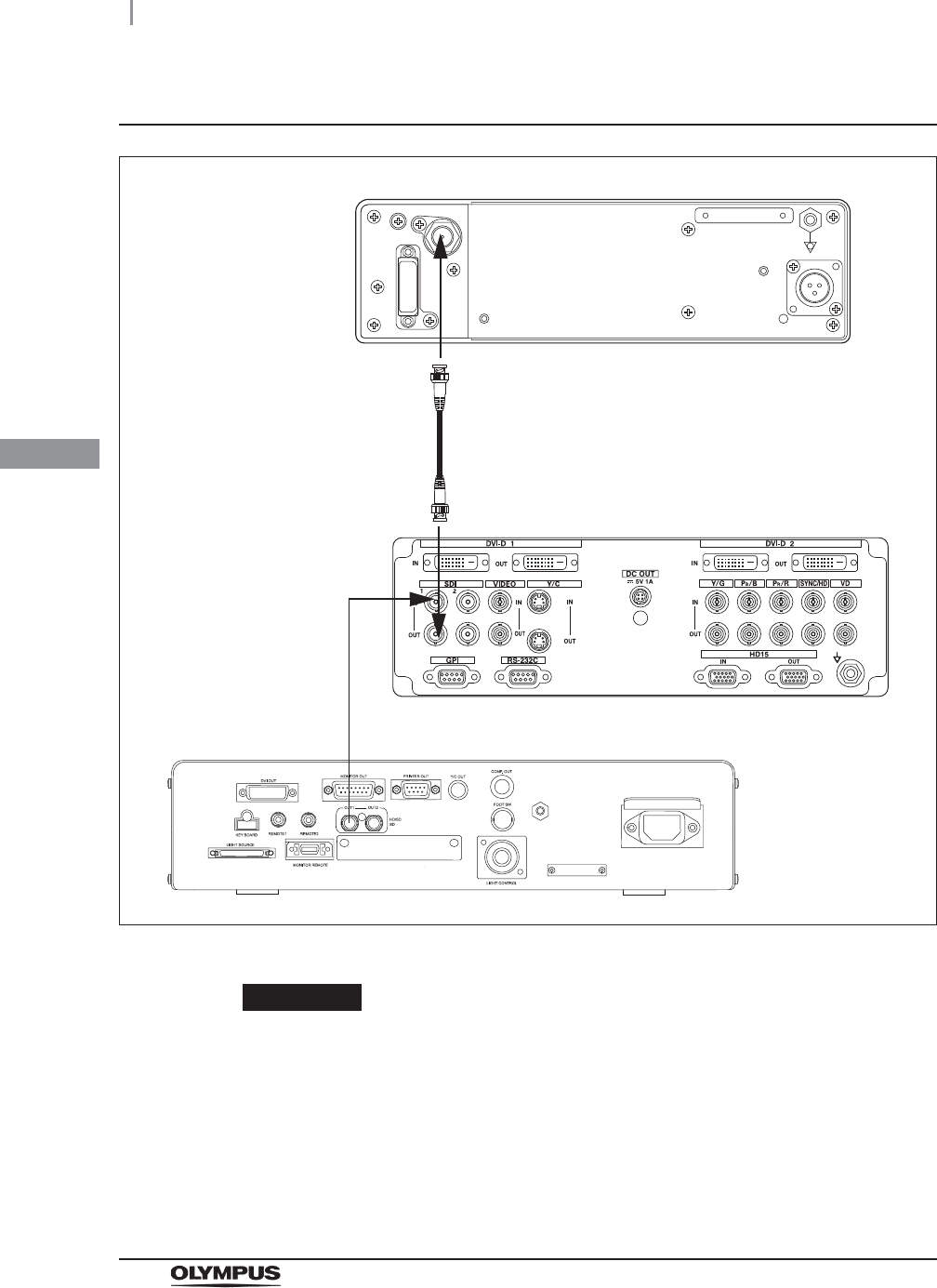
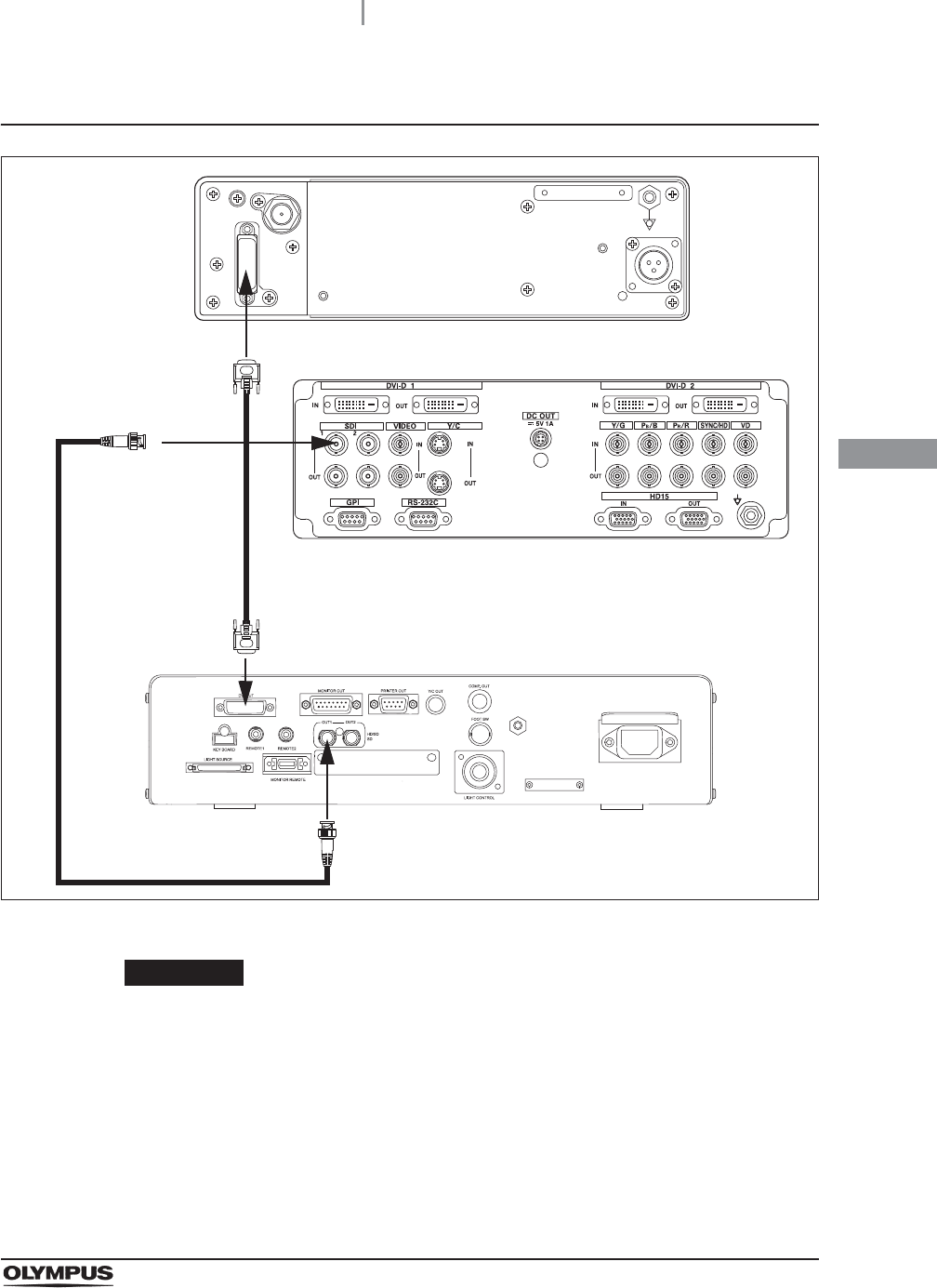
Connection diagram (When using HD-SDI)
Figure 3.7
CAUTION
• Ensure that the Wireless Transmitter is fixed firmly to the HD-SDI OUT terminal of
the high definition LCD monitor OEV261H.
• HD-SDI OUT terminal of the high definition LCD monitor OEV261H through outputs
the HD-SDI video signal of HD-SDI IN terminal from such as video system center.
Select HD-SDI output in the video output selection of the video system center. The
Wireless Transmitter doesn’t support SD-SDI. Do not select SD-SDI in the video
output selection.
SDI Cable
OEV261H
UWIT-Y0001-TX
OTV-S190
3.6 Connecting video cables to Wireless Transmitter
29
UWIT-Y0001-TX, UWIT-Y0001-RX INSTRUCTION MANUAL
Ch.3
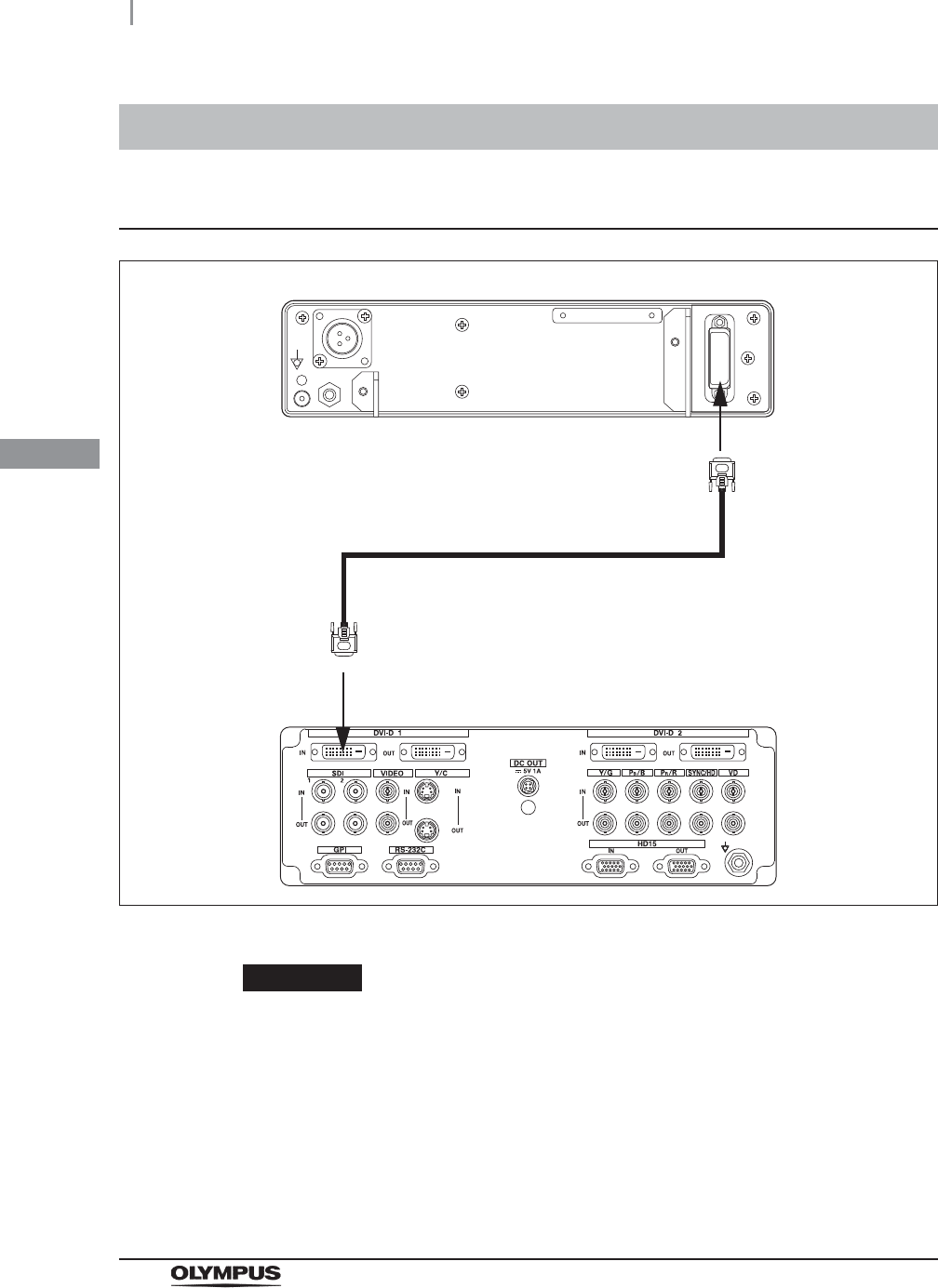
Connection diagram (When using DVI)
Figure 3.8
CAUTION
• Ensure that the Wireless Transmitter fixed firmly to the DVI-D OUT terminal of the
video system center or Image management HUB IMH-20.
• Select 1080p in the video output selection of the video system center. Do not select
the resolutions such as WUXGA in the video output selection that the Wireless
Transmitter doesn’t support.
• Connect the video system center and OEV261H directly by video cable such as
SDI cable (MAJ-1912, MAJ-1464, MAJ-1951).
UWIT-Y0001-TX
MAJ-1945
OEV261H
OTV-S190
MAJ-1912,
MAJ-1464,
MAJ-1951
30
3.7 Connecting video cables to Wireless Receiver
UWIT-Y0001-TX, UWIT-Y0001-RX INSTRUCTION MANUAL
Ch.3
Connection diagram
Figure 3.9
CAUTION
Ensure that the Wireless Receiver is fixed firmly to the DVI-D IN terminal of the
high definition LCD monitor OEV261H.
3.7 Connecting video cables to Wireless Receiver
UWIT-Y0001-RX
MAJ-1945
OEV261H

4.1 Inspection of the power supply
31
UWIT-Y0001-TX, UWIT-Y0001-RX INSTRUCTION MANUAL
Ch.4
Chapter 4 Inspection
Prepare the Wireless Image Transmitter Unit and other ancillary equipment before each particular
case. Refer to the respective instruction manuals for each piece of equipment.
WARNING
• Review Chapter 3, “Installation and Connection” thoroughly, and prepare the
instruments properly before inspection. If the equipment is not properly prepared
before each use, equipment damage, patient and operator injury and/or fire can
occur.
• Before each case, inspect the Wireless Image Transmitter Unit as instructed below.
Inspect other equipment to be used with this Wireless Image Transmitter Unit as
instructed in their respective instruction manuals. Should the slightest irregularity
be observed, do not use the Wireless image transmitter unit and see Chapter 7,
“Troubleshooting”. If the irregularity is still observed after consulting Chapter 7,
contact Olympus. Damage or irregularity may compromise patient or user safety
and may result in more severe equipment damage.
Power indicator lights on when the Wireless Transmitter or Receiver is powered. If power indicator
doesn’t light on, check the equipment as follows;
4.1 Inspection of the power supply
Confirm that the AC cord, AC adaptor, and the Wireless Transmitter or Receiver are
connected as described in Section 3.4, “Connecting AC adaptor to Wireless
Transmitter or Receiver” and in Section 3.5, “Connecting AC adaptor to an AC mains
power supply”.
32
4.2 Inspection of the displayed image
UWIT-Y0001-TX, UWIT-Y0001-RX INSTRUCTION MANUAL
Ch.4
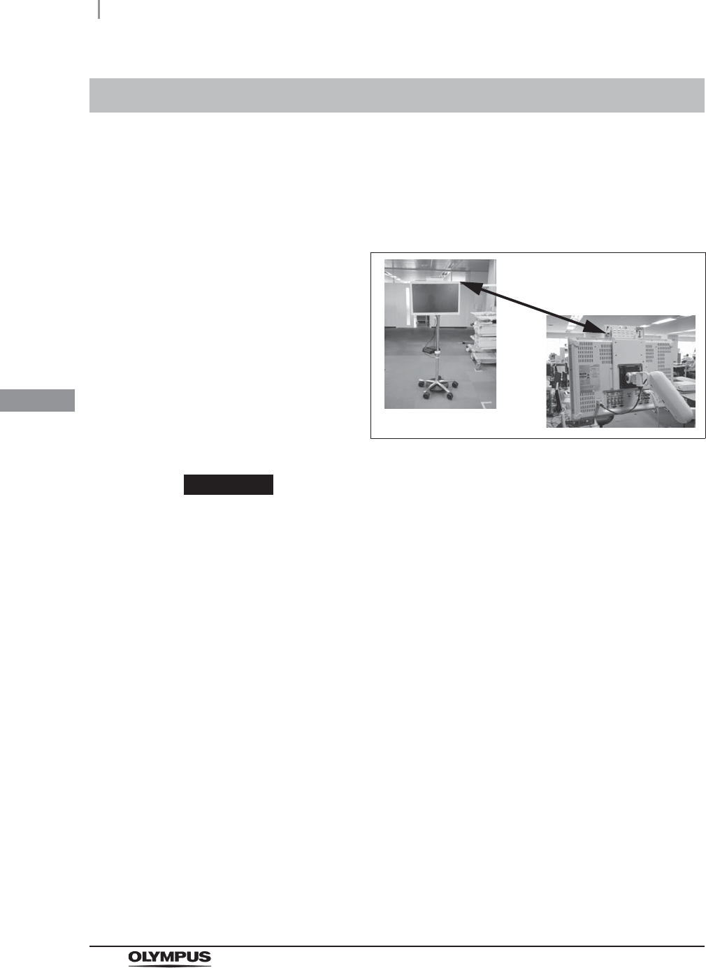
4.2 Inspection of the displayed image
Place the Wireless Transmitter and Receiver face to face without any obstruction in
between.
Typical communication distance of the Wireless Transmitter and Receiver is about 10 m.
Ensure that the distance between the Wireless Transmitter and Receiver is within 10 m.
Figure 4.1
CAUTION
• Do not stand or place obstacles in front of the Wireless Transmitter or Receiver,
which may interrupt the RF path.
• Noises or interruptions may appear on the image due to the RF interference when
the unit using same 60 GHz frequency bands is activated near the Wireless
Transmitter or Receiver. Confirm that the image is displayed normally before use.
• If the instruments located near the Wireless Transmitter or Receiver use same
60 GHz frequency bands or tend to accept influence of radio frequency, check the
instruments works normally by referring to such as the panel display of the
instruments after wireless transmission starts between the Wireless Transmitter
and Receiver.
• Do not place as described below. Noises may appear on the image because the
Wireless Transmitter or Receiver cannot perform normally.
Do not place the Wireless Transmitter or Receiver low because the RF path
may interrupted by the operator/patient or device.
Do not place the Wireless Transmitter or Receiver in different direction such as
to the ceiling or the floor because the RF path may become insufficient to
stabilize the Wireless Transmitter.
Do not set either one of the Wireless Transmitter or Receiver upright.

4.2 Inspection of the displayed image
33
UWIT-Y0001-TX, UWIT-Y0001-RX INSTRUCTION MANUAL
Ch.4
1Turn on the Wireless Transmitter, Receiver and peripheral devices and confirm the
image is displayed on the monitor which is connected to the Wireless Receiver.
2Confirm that the endoscopic image is normal by observing any object such as the
palm of your hand.

34
4.2 Inspection of the displayed image
UWIT-Y0001-TX, UWIT-Y0001-RX INSTRUCTION MANUAL
Ch.4

5.1 Turn the Wireless Transmitter and Receiver ON
35
UWIT-Y0001-TX, UWIT-Y0001-RX INSTRUCTION MANUAL
Ch.5
Chapter 5 Operation
When the mobile workstation (WM-NP1, WM-WP1,
WM-DP1) is used
CAUTION
After using the Wireless Transmitter or Receiver, turn the mobile workstation off.
When the mobile workstation (WM-NP1, WM-WP1,
WM-DP1) is not used
CAUTION
After using the Wireless Transmitter or Receiver, disconnect the AC cord from the
wall mains outlet or from the AC adaptor.
5.1 Turn the Wireless Transmitter and Receiver ON
Turn the mobile workstation ON.
Connect the AC cord of the Wireless Transmitter or Receiver to the wall mains outlet.

36
5.2 Connection of the Wireless Transmitter and Receiver
UWIT-Y0001-TX, UWIT-Y0001-RX INSTRUCTION MANUAL
Ch.5
CAUTION
• If multiple pairs of Wireless Transmitters and Receivers are to be used in adjacent
areas, the connection between the paired Wireless Transmitter and Receiver may
not complete, or the Wireless Transmitter may establish connection to the incorrect
Receiver (cross-talk). To avoid connection issues or cross-talk when multiple
Wireless Image Transmitter Units are installed, select different Channels and/or
turn off other Unit(s).
• When the Wireless Transmitter is turned off after the Wireless Transmitter and
Receiver are connected, the Wireless Receiver automatically searches a Wireless
Transmitter which is ready to connect. If the Wireless Receiver detects another
Wireless Transmitter which is ready to connect, they may connect automatically.
Operate as below to reconnect with the original Wireless Transmitter.
NOTE
• A Wireless Transmitter can connect to only one Wireless Receiver at a time.
• When the Wireless Transmitter or Receiver is turned OFF after connection has
been established, the Wireless Transmitter search same Receiver automatically
when turn ON. If the Wireless Receiver is ON and ready to connect, the Wireless
Transmitter connects to it automatically.
5.2 Connection of the Wireless Transmitter and
Receiver
1Prepare the Wireless Transmitter and Receiver to be connected, and turn them ON.
2Press and hold the SELECT button of Wireless Transmitter for about 1 second.
The Wireless Transmitter will seek connection to the Wireless Receiver when the
SELECT button is pressed and held for about 1 second. Ensure that the Wireless
Transmitter and Receiver have the same channel selected. To change the Channel, press
and hold the SELECT button again until the intended channel blinks.
3The CH light will blink during the connection process. The CH light will be steady once
the Wireless Transmitter and Receiver are connected.
If CH light continues to blink and connection cannot be established, please refer to
Chapter 7, “Troubleshooting”.

6.1 Care
37
UWIT-Y0001-TX, UWIT-Y0001-RX INSTRUCTION MANUAL
Ch.6
Chapter 6 Care, Storage, and Disposal
WARNING
• After wiping with a piece of moistened gauze, dry the Wireless Image Transmitter
Unit thoroughly before using it again. If it is used while still wet, there is the risk of
an electric shock.
• When cleaning the Wireless Image Transmitter Unit, always wear appropriate
personal protection equipment such as eye wear, face mask, moisture-resistant
clothing, and chemical-resistant gloves that fit properly and are long enough to that
your skin is not exposed. Blood, mucus, and other potentially infectious material
adhering to the Wireless Image Transmitter Unit could pose an infection control
risk.
CAUTION
• Do not clean the video connector socket and the AC mains power inlet. Cleaning
them can deform or corrode the contacts, which could damage the Wireless Image
Transmitter Unit.
• Do not wipe the external surface with hard or abrasive wiping material. The surface
will be scratched.
After using the Wireless Image Transmitter Unit, immediately perform the following cleaning
procedures. If cleaning is delayed, residual organic debris will begin to solidify, and it may be difficult to
effectively clean the Wireless Image Transmitter Unit. Always remove debris routinely.
6.1 Care
1Disconnect the power cords of Wireless Image Transmitter Unit from the wall mains
outlet or the power socket of the mobile workstation.
2When the Wireless Image Transmitter Unit is soiled with blood or other potentially
infectious materials, wipe off all debris using a piece of gauze moistened with neutral
detergent.
3Remove dust, dirt, and other stains on the surface by wiping with a piece of gauze
moistened with 70% ethyl or isopropyl alcohol.
4Make sure to dry the Wireless Image Transmitter Unit after wiping with 70% ethyl or
isopropyl alcohol.

38
6.2 Storage
UWIT-Y0001-TX, UWIT-Y0001-RX INSTRUCTION MANUAL
Ch.6
CAUTION
Do not store the Wireless Image Transmitter Unit in a location exposed to direct
sunlight, X-rays, radio activity or strong electromagnetic radiation (e.g., near
microwave medical treatment equipment, short-wave medical treatment
equipment, MRI, radio equipment, or cellular phones). Damage to the Wireless
Image Transmitter Unit may result.
When disposing of this instrument or any of its components (such as fuses), follow all applicable
national and local laws and guidelines.
6.2 Storage
1Disconnect the power cords of the Wireless Image Transmitter Unit from the wall
mains outlet or the power socket of the mobile workstation.
2Disconnect the cables connected to the Wireless Image Transmitter Unit.
3Store the equipment in the level position in a clean, dry, and stable location.
6.3 Disposal

7.1 Troubleshooting
39
UWIT-Y0001-TX, UWIT-Y0001-RX INSTRUCTION MANUAL
Ch.7
Chapter 7 Troubleshooting
If any irregularity is observed during inspection as described in Chapter 4, “Inspection” or using as
described in Chapter 5, “Operation”, do not use the Wireless Image Transmitter Unit and attempt to
solve the problem as described in Section 7.2, “Troubleshooting guide”. If the problem still cannot be
resolved, contact Olympus.
DANGER
Never use the Wireless Image Transmitter Unit if an irregularity is observed.
Damage or irregularity of the Wireless Image Transmitter Unit may compromise
patient or user safety and may result in more severe equipment damage.
7.1 Troubleshooting

40
7.2 Troubleshooting guide
UWIT-Y0001-TX, UWIT-Y0001-RX INSTRUCTION MANUAL
Ch.7
The following table shows the possible causes of and countermeasures against troubles that may
occur due to equipment setting errors or deterioration of consumable.
Troubles or failures other than those listed in the following table need repair. If repair is performed by
persons who are not qualified by Olympus, patient or user injury and/or equipment damage may result.
Be sure to contact Olympus for repair.
WARNING
If an irregularity is observed, turn the Wireless Image Transmitter Unit OFF once
and turn it ON again. If the irregularity cannot be solved, turn the Wireless Image
Transmitter Unit OFF and disconnect the power cord to stop the flow of electricity
completely.
7.2 Troubleshooting guide
Irregularity description Possible cause Solution
The power fails to come on. The AC adaptor is not connected
correctly.
Connect AC adaptor to Wireless
Transmitter or Receiver as described in
Section 3.4, “Connecting AC adaptor to
Wireless Transmitter or Receiver”.
The AC cord is not connected correctly. Connect AC cord to AC adaptor as
described in Section 3.5, “Connecting
AC adaptor to an AC mains power
supply”.
The mobile workstation is OFF. Turn the mobile workstation ON.
The endoscopic image does
not appear on the monitor
while SDI is blinking in the
video selection status
display.
The video system center is OFF. Turn the video system center ON.
The SDI cable is not connected
correctly.
Connect the SDI cable correctly.
A wire in the cable is disconnected. Replace the cable with new one.
Unsupported video signal such as
SD-SDI is input.
Input HD-SDI video signal.
The endoscopic image does
not appear on the monitor
while DVI is blinking in the
video selection status
display.
The video system center is OFF. Turn the video system center ON.
The DVI cable is not connected
correctly.
Connect the DVI cable correctly.
A wire in the cable is disconnected. Replace the cable with new one.
Unsupported video signal such as
WUXGA is selected as an input from
the video system center.
Input digital video signal of 1080p
(60Hz/50Hz) or SXGA: 1280 × 1024
(60Hz).
HDCP is input The Wireless Transmitter doesn’t
support HDCP. Connect with the device
which doesn’t output HDCP signal.

7.2 Troubleshooting guide
41
UWIT-Y0001-TX, UWIT-Y0001-RX INSTRUCTION MANUAL
Ch.7
The endoscopic image does
not appear on the monitor
while CH1 or CH2 blinks.
The CH of the transmitter and the
receiver is different.
Press the SELECT button of the
transmitter and set to same CH.
Other ID of the receiver remains in
transmitter.
Press the SELECT button to clear the
remained receiver ID. Press the
SELECT button again if the CH of the
transmitter and the receiver is different.
The Wireless Transmitter or Receiver is
used in same frequency range in the
vicinity. (RF interference).
Confirm the CH of the Wireless
Transmitter or Receiver in the vicinity
and set different CH.
The endoscopic image does
not appear on the monitor
while CH1 or CH2 lights on.
The monitor is OFF. Turn the monitor ON.
Different video input terminal is selected
in monitor.
Select appropriate video input terminal
in monitor.
The endoscopic image does
not appear on the monitor
while nothing lights on the
Wireless Transmitter or
Receiver.
The power cord is disconnected. Connect the power cord to AC adaptor
referring to Section 3.5, “Connecting
AC adaptor to an AC mains power
supply”.
The mobile workstation is OFF. Turn the mobile workstation ON.
Nothing lights on or blinks
other than power indicator.
This symptom may be caused by a
malfunction in the circuit of the Wireless
Transmitter or Receiver.
Turn the Wireless Transmitter or
Receiver off, wait 10 seconds or more
and turn on again. If the irregularity
cannot be solved, contact Olympus.
The Wireless Transmitter or
Receiver repeats reboot
automatically.
This symptom may be caused by a
malfunction in the circuit of the Wireless
Transmitter or Receiver.
Turn the Wireless Transmitter or
Receiver off, wait 10 seconds or more
and turn on again. If the irregularity
cannot be solved, contact Olympus.
Irregularity description Possible cause Solution

42
7.3 Returning the Wireless Image Transmitter Unit for repair
UWIT-Y0001-TX, UWIT-Y0001-RX INSTRUCTION MANUAL
Ch.7
CAUTION
Olympus is not liable for any injury or damage which occurs as a result of repairs
attempted by non-Olympus personnel.
When returning the Wireless Image Transmitter Unit for repair, contact Olympus. With the Wireless
Image Transmitter Unit, include a description of the malfunction or damage and the name and
telephone number of the individual at your location who is most familiar with the problem. Include a
repair purchase order.
7.3 Returning the Wireless Image Transmitter Unit
for repair

App.
Combination equipment
43
UWIT-Y0001-TX, UWIT-Y0001-RX INSTRUCTION MANUAL
Appendix
The equipment compatible with this endoscope and the EMC information are described in this
Appendix.
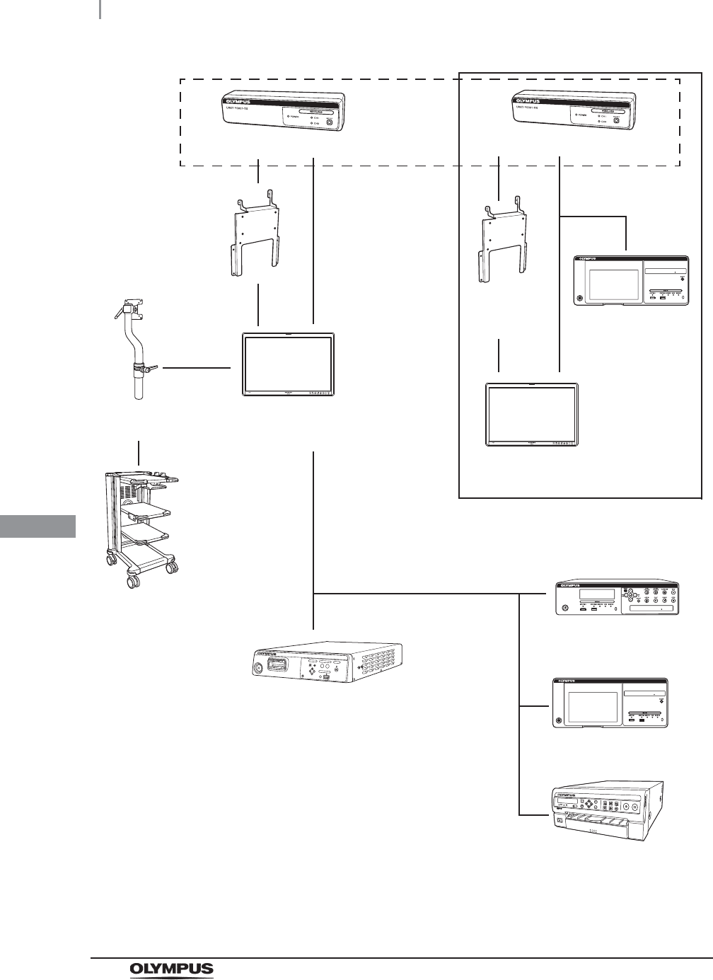
System chart
The recommended combinations of equipment that can be used with this Wireless Image Transmitter
Unit are listed below. New products released after the introduction of the Wireless Image Transmitter
Unit may also be compatible for use in combination with it. For further details, contact Olympus.
WARNING
If combinations of equipment other than those shown below are used, the full
responsibility should be assumed by the medical treatment facility. Such
combinations do not only allow the equipment to manifest their full functionality but
may also imperil the safety of the patient and medical personnel. In addition, the
endurance of the Wireless Image Transmitter Unit and ancillary equipment is not
guaranteed. Troubles caused in this case are not covered by free-of-charge repair.
Be sure to use the equipment in one of the recommended combinations.
Combination equipment
App.
44
Combination equipment
UWIT-Y0001-TX, UWIT-Y0001-RX INSTRUCTION MANUAL
High definition LCD
monitor (OEV261H)
Mobile Workstation
(WM-NP1, WM-WP1,
WM-DP1)
VISERA ELITE video system center
(OTV-S190)
EVIS EXCERA III video system center
(CV-190)
High definition LCD
monitor (OEV261H)
Attachment
for UWIT
(MAJ-Y0149)
Wireless Transmitter (UWIT-Y0001-TX)
LCD Arm
(MAJ-181)
Wireless Receiver (UWIT-Y0001-RX)
Install the high definition LCD monitor
OEV261H with Wireless Receiver in the
level position in a stable location.
* These products enclosed with the dotted line conform to EMC (Ed.3)
Attachment
for UWIT
(MAJ-Y0149) Image management
HUB (IMH-20)
Image management HUB
(IMH-10)
Image management HUB
(IMH-20)
Color video printer
(OEP-5)

App.
FCC (for Wireless Transmitter and Receiver)
45
UWIT-Y0001-TX, UWIT-Y0001-RX INSTRUCTION MANUAL
This equipment has been tested and found to comply with the limits for a Class B digital device,
pursuant to part 15 of the FCC Rules. These limits are designed to provide reasonable protection
against harmful interference in a residential installation. This equipment generates uses and can
radiate radio frequency energy and, if not installed and used in accordance with the instructions, may
cause harmful interference to radio communications. However, there is no guarantee that interference
will not occur in a particular installation. If this equipment does cause harmful interference to radio or
television, reception, which can be determined by turning the equipment off and on, the user is
encouraged to try to correct the interference by one or more of the following measures:
• Reorient or relocate the receiving antenna.
• Increase the separation between the equipment and receiver.
• Connect the equipment into an outlet on a circuit different from that to which the receiver is
connected.
• Consult the dealer or an experienced radio/TV technician for help.
This equipment complies with FCC/IC radiation exposure limits set forth for a controlled environment
and meets the FCC radio frequency (RF) Exposure Guidelines in Supplement C to OET65 and
RSS-102 of the IC radio frequency (RF) Exposure rules. This equipment has very low levels of RF
energy that it deemed to comply without maximum permissive exposure evaluation (MPE). But it
should be installed and operated keeping the radiator at least 20 cm or more away from person’s body
(excluding extremities: hands, wrists, feet and ankles).
Cet équipement est conforme aux limites d’exposition aux rayonnements énoncées pour un
environnement contrôlé et respecte les régles les radioélectriques (RF) de la FCC lignes directrices
d’exposition dans le Supplément C à OET65 et d’exposition aux fréquences radioélectriques (RF)
CNR-102 de l’IC. Cet équipement émet une énergie RF très faible qui est considérée conforme sans
évaluation de l’exposition maximale autorisée. Cependant, cet équipement doit être installé et utilisé
en gardant une distance de 20 cm ou plus entre le dispositif rayonnant et le corps (à l’exception des
extrémités: mains, poignets, pieds et chevilles).
FCC (for Wireless Transmitter and Receiver)
FCC/IC (for Wireless Transmitter and Receiver)

App.
46
Specifications
UWIT-Y0001-TX, UWIT-Y0001-RX INSTRUCTION MANUAL
Environment
Specifications
Operating
environment
Ambient temperature 10 – 40qC (50 – 104qF)
Relative humidity 30 – 85% (without condensation)
Atmospheric
pressure 700 – 1060 hPa
Usage location Indoor use only
Transportation and
storage environment
Ambient temperature –25 to +70qC (–13 to +158qF)
Relative humidity 10 – 90%
Atmospheric
pressure 700 – 1060 hPa
App.
Specifications
47
UWIT-Y0001-TX, UWIT-Y0001-RX INSTRUCTION MANUAL
Maximum 2 pairs (2 Transmitters, 2 Receivers) can be used simultaneously in a room completely
enclosed by walls and doors. Set CH1 for one pair and CH2 for the other.
CAUTION
• Inspect the unit before use as described in this manual.
• Do not use more than 2 pairs in an enclosed room simultaneously. If more than 2
pairs are used simultaneously, interference may cause noise or interruption of
images.
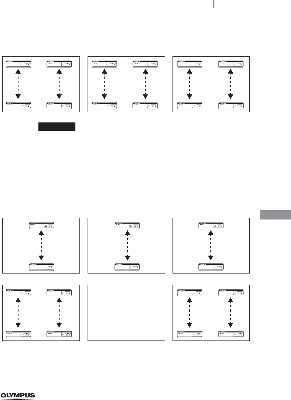
• The RF signal may go beyond the wall of room due to the material of the wall (e.g.,
part of the wall is glass). In that case, confirm before use that no interference from
neighboring rooms by using different Channels in neighboring rooms as shown
below. If interference still occurs, consider installing the Wireless Image Transmitter
Unit in alternating rooms (every other room).
CH1 CH2 CH1 CH2 CH1 CH2
CH1 CH2 CH1
CH1 CH2 CH1 CH2

App.
48
Specifications
UWIT-Y0001-TX, UWIT-Y0001-RX INSTRUCTION MANUAL
Specifications
UWIT-Y0001-TX Dimensions 234 (W) × 69 (H) × 43 (D) mm
Dimensions (maximum) 234 (W) × 69 (H) × 59 (D) mm
Weight 0.41 kg
Voltage DC 12 V, 1 A
Video signal
input
SDI input
connector BNC (×1)
DVI input
connector
DVI (×1)
No support for HDCP
UWIT-Y0001-RX Dimensions 208 (W) × 54 (H) × 45 (D) mm
Dimensions (maximum) 208 (W) × 54 (H) × 60 (D) mm
Weight 0.31 kg
Voltage DC 12 V, 0.8 A
Video signal
output
DVI output
connector DVI (×1)
AC adaptor Dimensions 120 (W) × 38 (H) × 60 (D) mm
Dimensions (include cable) 3020 (W) × 38 (H) × 60 (D) mm
Weight 0.34 kg
Voltage AC IN 100 – 240 V, 50/60 Hz, 1 – 0.5 A
DC OUT 12 V, 3 A
EMC Applied standard IEC 60601-1-2: 2001
• This instrument complies with the EMC standard for medical
electrical equipment, edition 2 (IEC 60601-1-2: 2001). However,
when connecting to an instrument that complies with the EMC
standard for medical electrical equipment, edition 1
(IEC 60601-1-2: 1993), the whole system complies with
edition 1.
• CISPR 11 of emission:
Group 1, Class B
Year of manufacture The last digit of the year of manufacture is the second digit of the
serial number. In this example, the year is 2009.
Ex. 7901234 (serial number)
FCC ID UWIT-Y0001-TX: S8Q-RU5796
UWIT-Y0001-RX: S8Q-RU5808
This device complies with part 15 of the FCC Rules (FCC Part 15
Subpart C §15.255). Operation is subject to the following two
conditions:
(1) This device may not cause harmful interference, and (2) this
device must accept any interference received, including
interference that may cause undesired operation. This transmitter
must not be co-located or operated in conjunction with any other
antenna or transmitter.

App.
Specifications
49
UWIT-Y0001-TX, UWIT-Y0001-RX INSTRUCTION MANUAL
IC UWIT-Y0001-TX: 4763B-RU5796
UWIT-Y0001-RX: 4763B-RU5808
This device complies with Industry Canada license-exempt RSS
standard(s).
Operation is subject to the following two conditions:
(1) This device may not cause interference, and (2) this device
must accept any interference, including interference that may
cause undesired operation of the device.
Le présent appareil est conforme aux CNR d’Industrie Canada
applicables aux appareils radio exempts de licence. L’exploitation
est autorisée aux deux conditions suivantes:
(1) l’appareil ne doit pas produire de brouillage, et (2) l’utilisateur
de l’appareil doit accepter tout brouillage radioélectrique subi,
méme si le brouillage est susceptible d’en compromettre le
fonctionnement.
This Class B digital apparatus complies with Canadian ICES-003.
Cet appareil numérique de la classe B est conforme à la norme
NMB-003 du Canada.

App.
50
EMC information
UWIT-Y0001-TX, UWIT-Y0001-RX INSTRUCTION MANUAL
This model is intended for use in the electromagnetic environments specified below. The user and the
medical staff should ensure that it is used only in these environments.
Magnetic emission compliance information and recommended
electromagnetic environments
EMC information
Emission standard Compliance Guidance
RF emissions
CISPR 11
Group 1 This instrument uses RF (Radio Frequency) energy only for its
internal function. Therefore, its RF emissions are very low and are not
likely to cause any interference in nearby electronic equipment.
Radiated emissions
CISPR 11
Class B This instrument’s RF emissions are very low and are not likely to
cause any interference in nearby electronic equipment.
Main terminal
conducted emissions
CISPR 11
Harmonic emissions
IEC 61000-3-2
Class A This instrument’s harmonic emissions are low and are not likely to
cause any problem in the typical commercial power supply connected
to this instrument.
Voltage
fluctuations/flicker
emissions
IEC 61000-3-3
Complies This instrument stabilizes its own radio variability and has no effect
such as flicker in lighting apparatus.

App.
EMC information
51
UWIT-Y0001-TX, UWIT-Y0001-RX INSTRUCTION MANUAL
Electromagnetic immunity compliance information and
recommended electromagnetic environments
NOTE
UT is the AC mains power supply prior to application of the test level.
Immunity test IEC 60601-1-2
test level Compliance level Guidance
Electrostatic
discharge (ESD)
IEC 61000-4-2
Contact:
r2, r4, r6kV
Air:
r2, r4, r8kV
Same as left Floors should be made of wood, concrete, or
ceramic tile that hardly produces static. If
floors are covered with synthetic material that
tends to produce static, the relative humidity
should be at least 30%.
Electrical fast
transient/burst
IEC 61000-4-4
r2kV
for power supply lines
r1kV
for input/output lines
Same as left Mains power quality should be that of a typical
commercial (original condition feeding the
facilities) or hospital environment.
Surge
IEC 61000-4-5
Differential mode:
r0.5, r1kV
Common mode:
r0.5, r1, r2kV
Same as left Mains power quality should be that of a typical
commercial or hospital environment.
Voltage dips, short
interruptions, and
voltage variations
on power supply
input lines
IEC 61000-4-11
< 5% UT
(> 95% dip in UT)
for 0.5 cycle
Same as left Mains power quality should be that of a typical
commercial or hospital environment. If the
user of this instrument requires continued
operation during power mains interruptions, it
is recommended that this instrument be
powered from an uninterruptible power supply
or a battery.
40% UT
(60% dip in UT)
for 5 cycle
70% UT
(30% dip in UT)
for 25 cycle
< 5% UT
(> 95% dip in UT)
for 5 seconds
Power frequency
(50/60 Hz)
magnetic field
IEC 61000-4-8
3 A/m Same as left It is recommended to use this instrument by
maintaining enough distance from any
equipment that operates with high current.
App.
52
EMC information
UWIT-Y0001-TX, UWIT-Y0001-RX INSTRUCTION MANUAL
Cautions and recommended electromagnetic environment
regarding portable and mobile RF communications equipment,
such as cellular phones
NOTE
• Where “P” is the maximum output power rating of the transmitter*1 in watts (W)
according to the transmitter*1 manufacturer, and “d” is the recommended
separation distance in meters (m).
• This instrument complies with the requirements of IEC 60601-1-2: 2001 and
IEC 60601-1-2: 2007. However, under an electromagnetic environment that
exceeds its noise level, electromagnetic interference may occur on this instrument.
• Electromagnetic interference may occur on this instrument near a high-frequency
electrosurgical equipment and/or other equipment marked with the following
symbol:
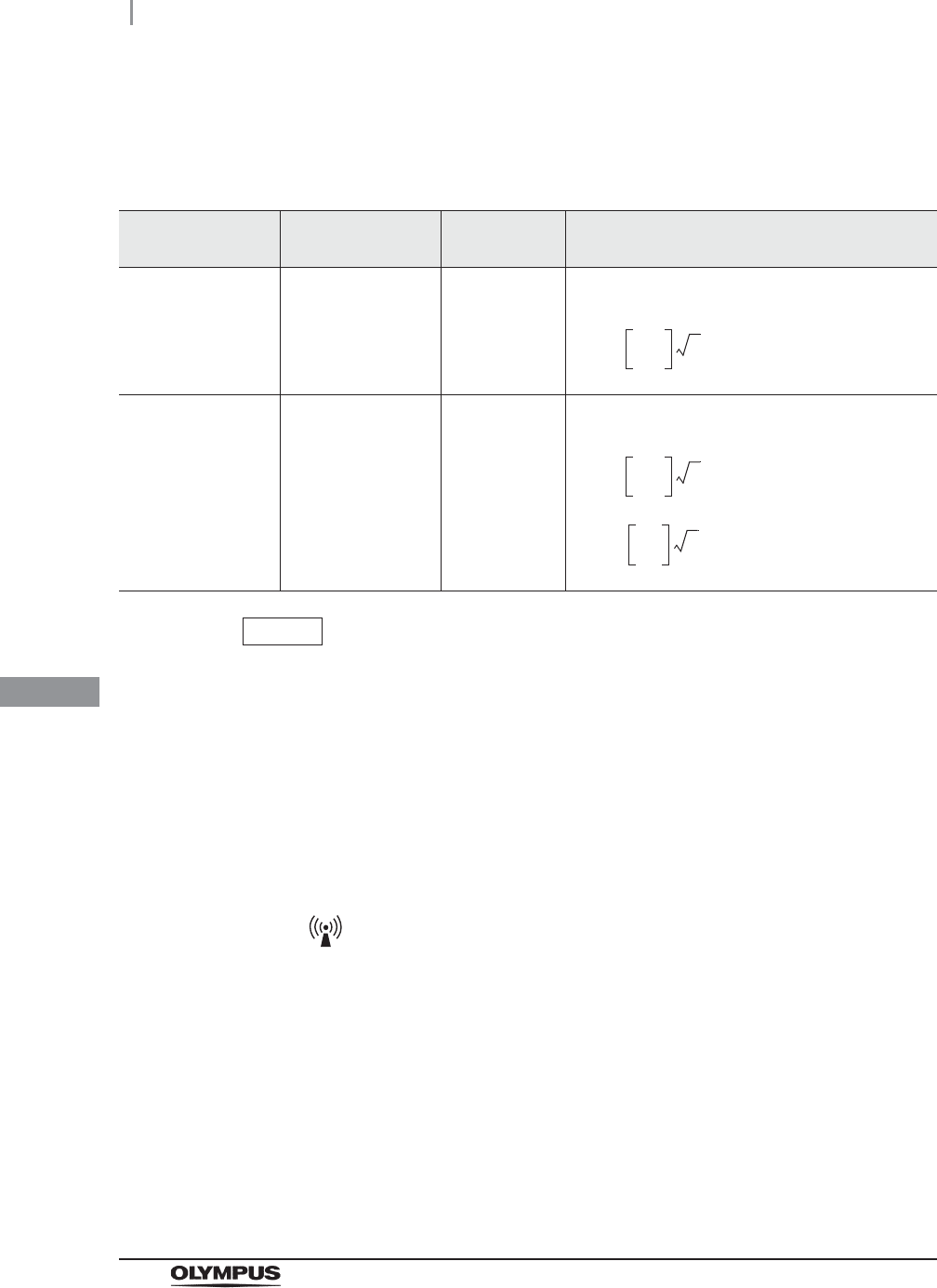
Immunity test IEC 60601-1-2
test level
Compliance
level Guidance
Conducted RF
IEC 61000-4-6
3Vrms
(150 kHz – 80 MHz)
3V (V
1) Formula for recommended separation distance
(V1=3 according to the compliance level)
Radiated RF
IEC 61000-4-3
3V/m
(80 MHz – 2.5 GHz)
3V/m (E
1) Formula for recommended separation distance
(E1=3 according to the compliance level)
80 MHz – 800 MHz
800 MHz – 2.5 GHz
*1 The word “Transmitter” is generic term used for conventional portable and
mobile RF communication equipment such as cellular phones.
d3.5
V1
------- P=
d3.5
E1
------- P=
d7
E1
------P=

App.
EMC information
53
UWIT-Y0001-TX, UWIT-Y0001-RX INSTRUCTION MANUAL
Recommended separation distance between portable and mobile
RF communications equipment and this instrument
NOTE
The guidance may not apply in some situations. Electromagnetic propagation is
affected by absorption and reflection from structures, objects, and people.
Portable and mobile RF communications equipment such as cellular phones
should be used no closer to any part of this instrument, including cables than the
recommended separation distance calculated from the equation applicable to the
frequency of the transmitter*1.
Rated maximum output
power of transmitter*1
P (W)
Separation distance according to frequency of transmitter*1 (m)
(calculated as V1=3 and E1=3)
150 kHz – 80 MHz 80 MHz – 800 MHz 800 MHz – 2.5 GHz
0.01 0.12 0.12 0.23
0.1 0.38 0.38 0.73
11.2 1.2 2.3
10 3.8 3.8 7.3
100 12 12 23
1 The word “Transmitter” is generic term used for conventional portable and
mobile RF communication equipment such as cellular phones.
d1.2 P=
d1.2 P=
d2.3 P=

App.
54
FCC WARNING
UWIT-Y0001-TX, UWIT-Y0001-RX INSTRUCTION MANUAL
Change or modifications not expressly approved by the party responsible for compliance could void
the user’s authority to operate the equipment. The shielded interface cable recommended in this
manual must be used with this equipment in order to comply with the limits for a digital device pursuant
to Subpart B of Part 15 of FCC Rules.
FCC WARNING
Declaration of Conformity
Trade Name: OLYMPUS MEDICAL SYSTEMS
Model: UWIT-Y0001-TX, UWIT-Y0001-RX
Responsible Party: OLYMPUS AMERICA INC.
Address: 3500 Corporate Parkway, P.O. Box 610 Center Valley,
PA 18034-0610, U.S.A.
Telephone Number: (484)896-5000

©2011 OLYMPUS MEDICAL SYSTEMS CORP. All rights reserved.
No part of this publication may be reproduced or distributed without the
express written permission of OLYMPUS MEDICAL SYSTEMS CORP.
OLYMPUS is a registered trademark of OLYMPUS CORPORATION.
Trademarks, product names, logos, or trade names used in this
document are generally registered trademarks or trademarks of each
company.

Printed in Japan 20110629 *0000
XGT8045 01
Manufactured by
2951 Ishikawa-cho, Hachioji-shi, Tokyo 192-8507, Japan
Fax: (042)646-2429 Telephone: (042)642-2111
(Premises/Goods delivery) Wendenstrasse 14-18, 20097 Hamburg, Germany
(Letters) Postfach 10 49 08, 20034 Hamburg, Germany
3500 Corporate Parkway, P.O. Box 610, Center Valley, PA
18034-0610, U.S.A.
Fax: (484)896-7128 Telephone: (484)896-5000
KeyMed House, Stock Road, Southend-on-Sea, Essex SS2 5QH, United Kingdom
Fax: (01702)465677 Telephone: (01702)616333
491B, River Valley Road #12-01/04, Valley Point Office Tower, Singapore 248373
Fax: 6834-2438 Telephone: 6834-0010
A8F, Ping An International Financial Center, No. 1-3, Xinyuan South Road,
Chaoyang District, Beijing, 100027 P.R.C.
Fax: (86)10-5976-1299 Telephone: (86)10-5819-9000
117071, Moscow, Malaya Kaluzhskaya 19, bld. 1, fl.2, Russia
Fax: (095)958-2277 Telephone: (095)958-2245
31 Gilby Road, Mount Waverley, VIC., 3149, Australia
Fax: (03)9543-1350 Telephone: (03)9265-5400
5301 Blue Lagoon Drive, Suite 290 Miami, FL 33126-2097, U.S.A.
Fax: (305)261-4421 Telephone: (305)266-2332
Distributed by
Olympus-Tower, 114-9 Samseong-Dong, Gangnam-Gu, Seoul 135-090 Korea
Fax: (02)6255-3494 Telephone: (02)6255-3210
Fax: (040)23773-4656 Telephone: (040)23773-0