Olympus Medical Systems RU8354 Automated Endoscope Leak Tester User Manual XGT8512 0100 fm10
Olympus Medical Systems Corp. Automated Endoscope Leak Tester XGT8512 0100 fm10
UserManual.wiki
>
Olympus Medical Systems
>
RU8354 User Manual
User Manual
Navigation menu
Upload a User Manual
Namespaces
Wiki Guide
HTML
PDF
Info
Views
User Manual
Discussion / Help
Navigation
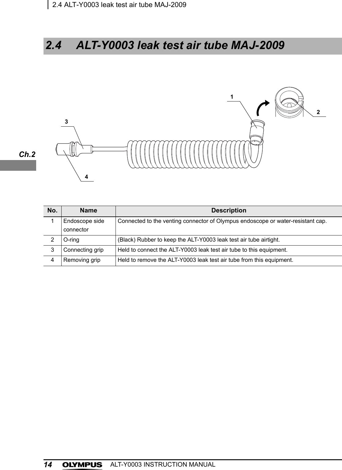
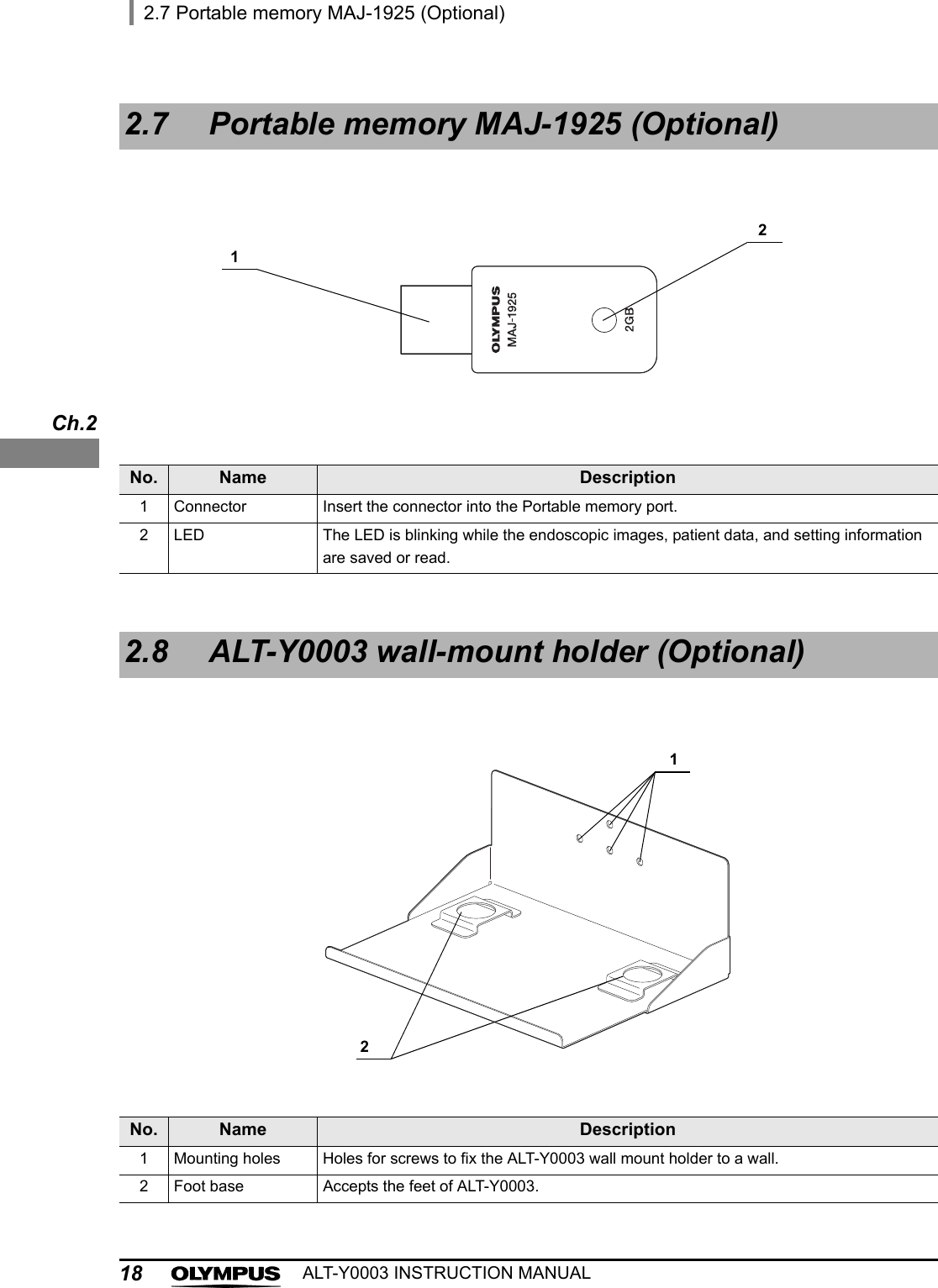
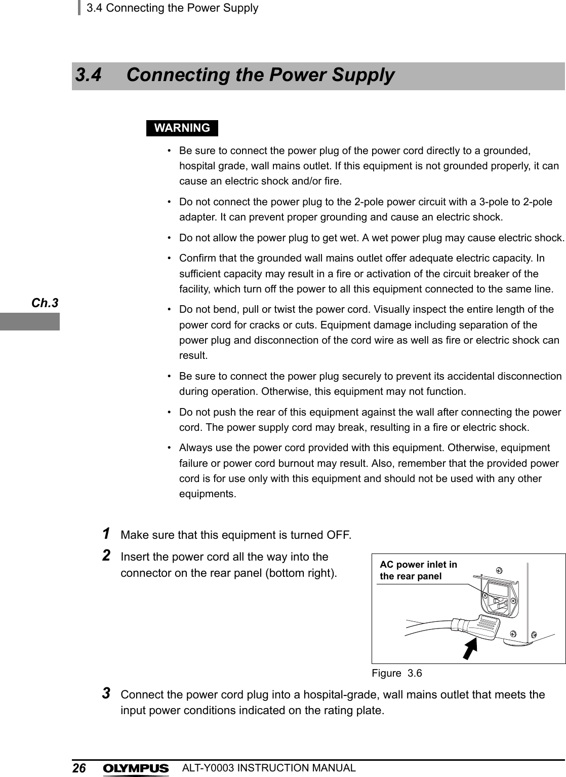
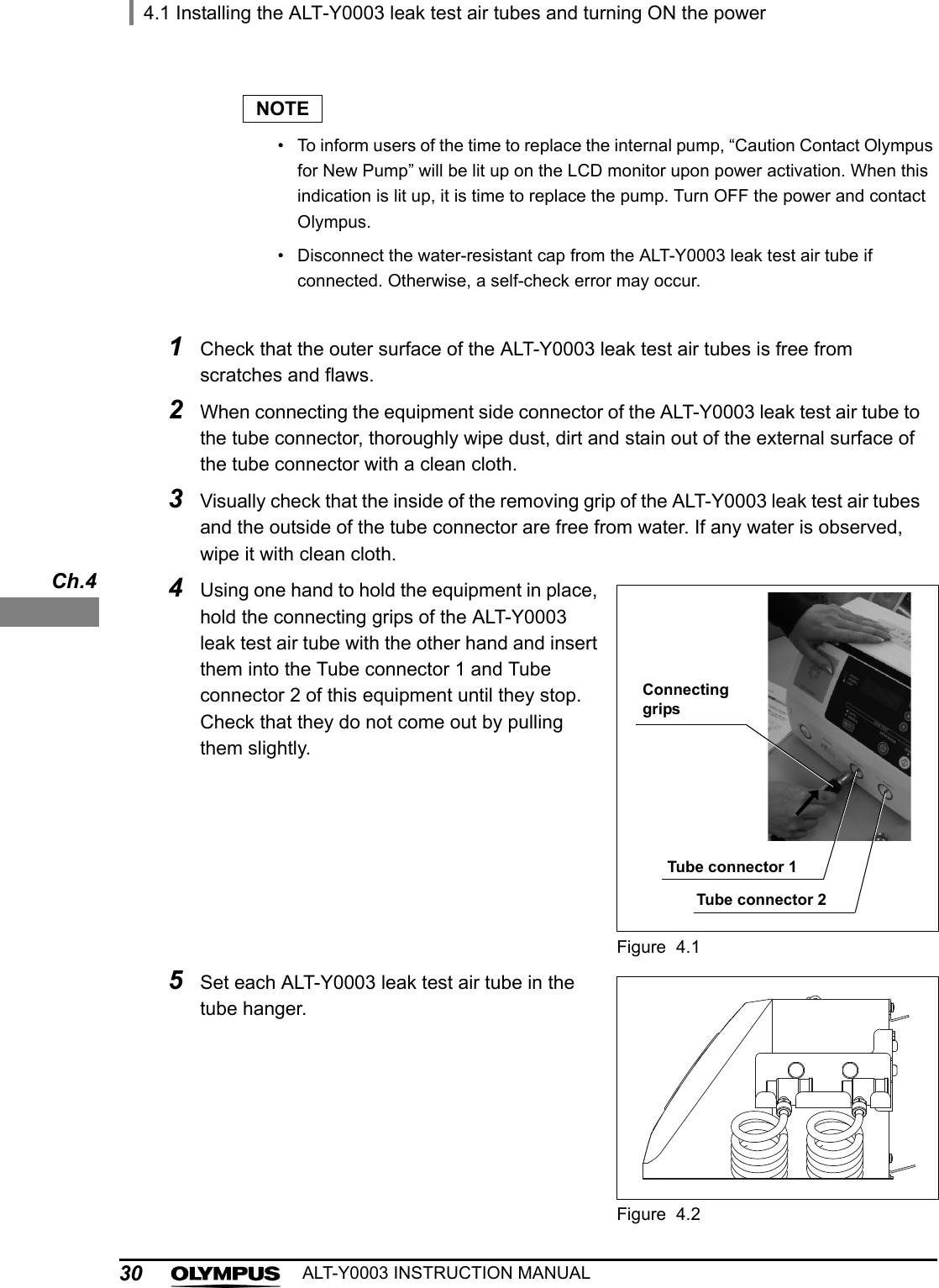
![iiContentsALT-Y0003 INSTRUCTION MANUALChapter 4 Inspection Before Use ........................................................ 294.1 Installing the ALT-Y0003 leak test air tubes and turning ON the power ............ 294.2 Self-check ................................................................................................................ 32If the error code [E112] is displayed during self-check ........................................................ 334.3 Checking the printer paper roll ............................................................................. 34Chapter 5 Operation ............................................................................. 355.1 Precautions for operation ...................................................................................... 355.2 Operation workflow ................................................................................................ 375.3 Preparation before use ........................................................................................... 385.4 Power activation ..................................................................................................... 395.5 Recognition of scope ID ........................................................................................ 405.6 Connecting ALT-Y0003 leak test air tubes and endoscope ................................ 445.7 Recognition of user ID ........................................................................................... 465.8 Automated leakage testing .................................................................................... 47The results in the automated leakage testing are all PASS: ................................................ 50If the result of leakage testing for at least one endoscope is FAIL ...................................... 515.9 Manual leakage testing .......................................................................................... 52Chapter 6 Routine Maintenance .......................................................... 576.1 Summary ................................................................................................................. 576.2 Care of ALT-Y0003 leak test air tubes ................................................................... 58When any debris remains on the surface ............................................................................ 59When no debris remains on the surface .............................................................................. 606.3 Turning power OFF and cleaning outer surface .................................................. 616.4 Installing the printer paper roll .............................................................................. 626.5 Replacing the fuse .................................................................................................. 656.6 Storage .................................................................................................................... 67](https://usermanual.wiki/Olympus-Medical-Systems/RU8354/User-Guide-1821797-Page-4.png)
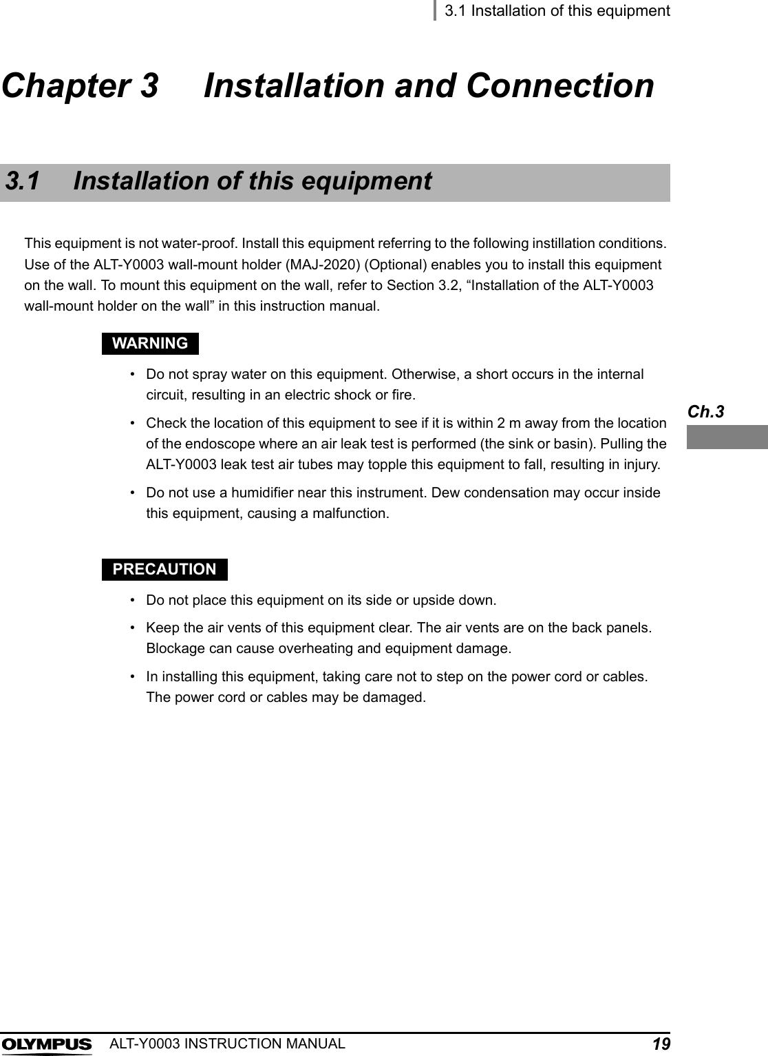
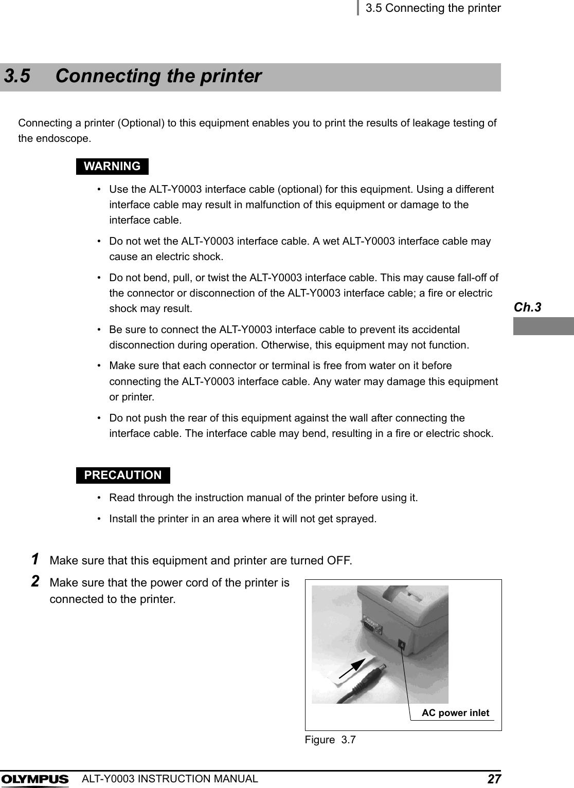
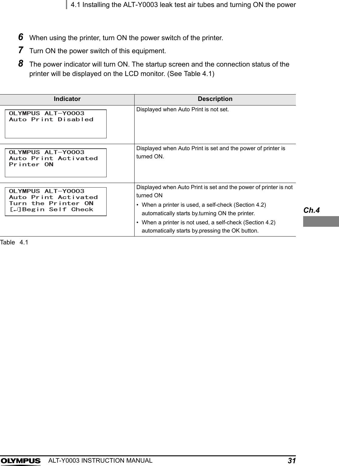
![ContentsiiiALT-Y0003 INSTRUCTION MANUALChapter 7 Other Functions .................................................................. 697.1 Setting date ............................................................................................................. 697.2 Setting time ............................................................................................................. 707.3 Performing only self-check ................................................................................... 717.4 Setting automated leakage test mode .................................................................. 727.5 Setting print mode .................................................................................................. 74Manual printing .................................................................................................................... 75Auto Print ............................................................................................................................. 80When the error code [E094] is displayed during printing ..................................................... 817.6 Data display ............................................................................................................ 82Leak Test Log Display ......................................................................................................... 82Error Log Display ................................................................................................................. 847.7 Download to a portable memory ........................................................................... 85Downloading data ................................................................................................................ 87Formatting the portable memory .......................................................................................... 897.8 Management of portable memory data in personal computer ........................... 90Folder structure ................................................................................................................... 91Chapter 8 Troubleshooting .................................................................. 938.1 Troubleshooting guide ........................................................................................... 938.2 Return of this equipment for repair ...................................................................... 98Appendix ................................................................................................. 99Compatible equipments .................................................................................................. 99System chart ........................................................................................................................ 99Specification .................................................................................................................. 101Environment ...................................................................................................................... 101Specifications ..................................................................................................................... 101EMC information ............................................................................................................ 103](https://usermanual.wiki/Olympus-Medical-Systems/RU8354/User-Guide-1821797-Page-5.png)
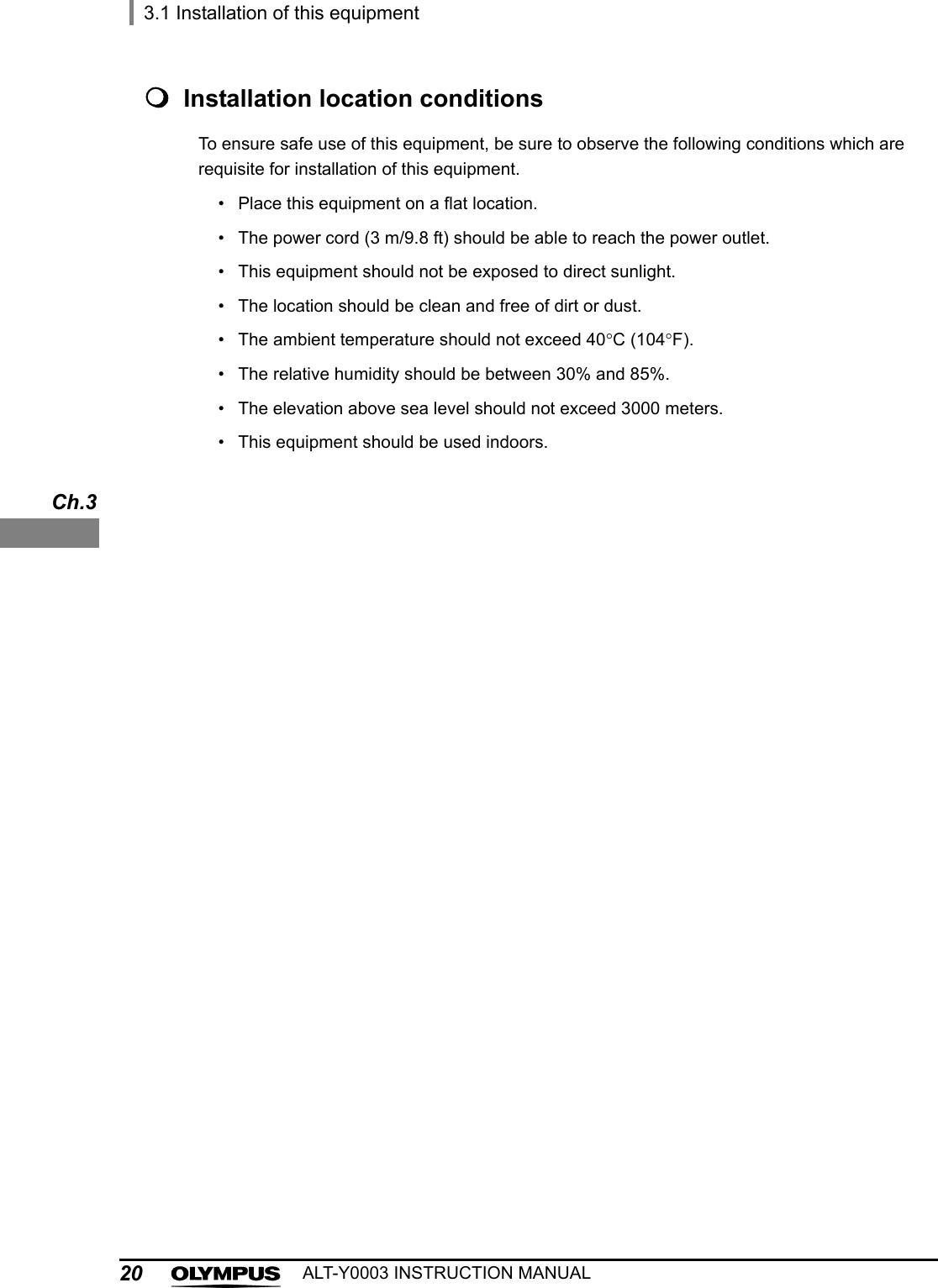
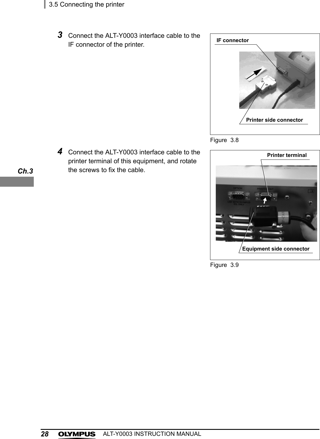
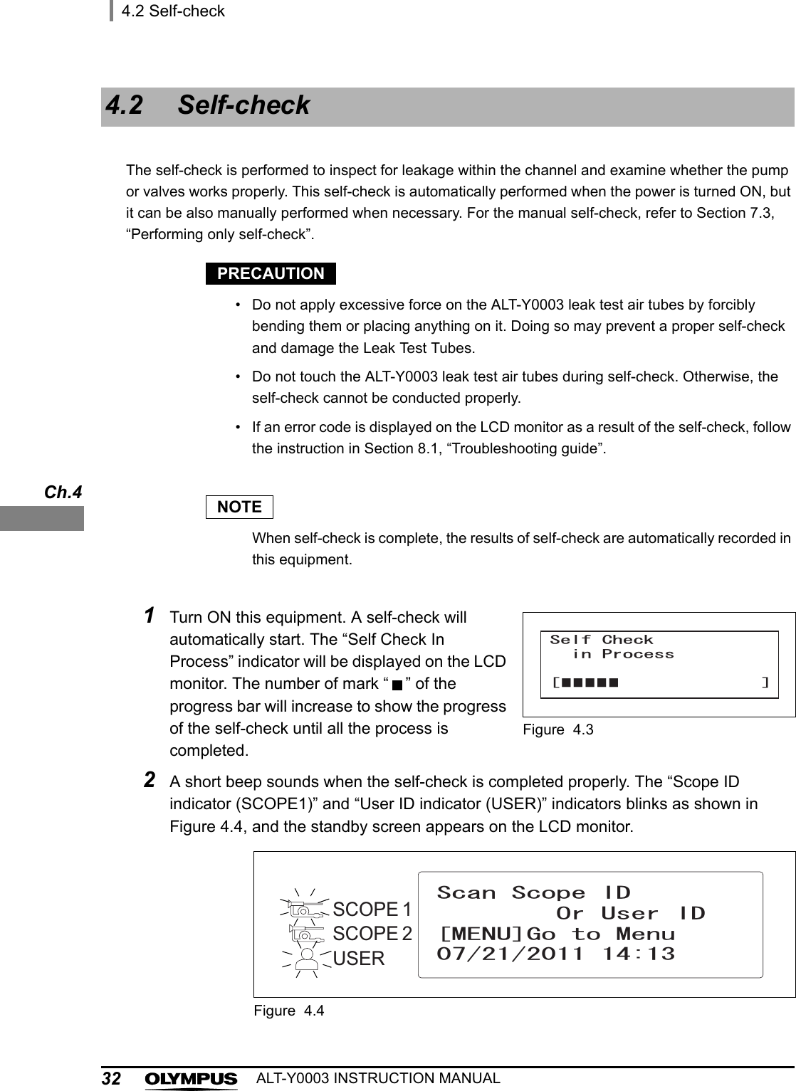
![4Important Information — Please Read Before UseALT-Y0003 INSTRUCTION MANUALCSV file formatThis is one data format most frequently used by statistical processing software. Each item of data (record) is accommodated in a single line, in which each item is delimited by “,” (a comma). This data is useful when executing statistical processing using commercially available statistical processing software.Wall mains outlet:A three-pin outlet having an exclusive terminal for grounding.Error CodeA code consisting of [E] and a three-digit number is displayed on the LCD monitor, if there is a problem with this equipment. When an error code is displayed, check the error code list to find out what corrective measures to take.User qualificationsThe operator of this equipment must be sufficiently trained in reprocessing of endoscopes. The medical literature reports cases of infections due to inappropriate cleaning, disinfection, and /or sterilization. Thoroughly review and understand the following items before use:Cleaning, disinfection, and sterilization procedures described in the instruction manuals for the endoscope and ancillary equipmentProfessional health and safety standardsApplicable guidelines on cleaning, disinfection, and sterilization of endoscopy equipment.Structure and handling of endoscopic equipmentPersonal protective equipment requirements to minimize exposure to chemicals and infectious materials.This manual does not explain or discuss details of cleaning, disinfection, and sterilization.Equipment compatibilityUse this equipment in combination with ancillary equipment listed in System Chart in Appendix. Using incompatible equipment can result in patient or operator injury and equipment damage and/or malfunction. Refer to the “List of Compatible Endoscopes <ALT-Y0003>” for compatible types of endoscope.Do not use this equipment in combination with non-Olympus endoscopes; Olympus has not tested the efficacy of detecting leakage with this equipment other than those combinations designated.](https://usermanual.wiki/Olympus-Medical-Systems/RU8354/User-Guide-1821797-Page-10.png)
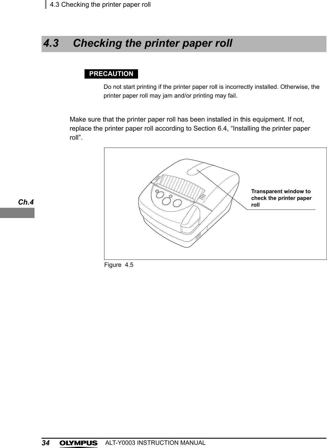
![4.2 Self-check33ALT-Y0003 INSTRUCTION MANUALCh.4If the error code [E112] is displayed during self-checkIf the error code [E112] is displayed in the self-check, make sure the connection between this equipment and this equipment side connector of the ALT-Y0003 leak test air tube is proper. Press the Enter button to display the Standby screen and restart a self-check referring to Section 7.3. If the error code [E112] is still displayed, an irregularity may have occurred in this equipment. Turn OFF the power switch and contact Olympus.3When using this equipment for the first time, set the date and time according to Section 7.1, “Setting date” and Section 7.2, “Setting time”.4Turn OFF this equipment.](https://usermanual.wiki/Olympus-Medical-Systems/RU8354/User-Guide-1821797-Page-39.png)
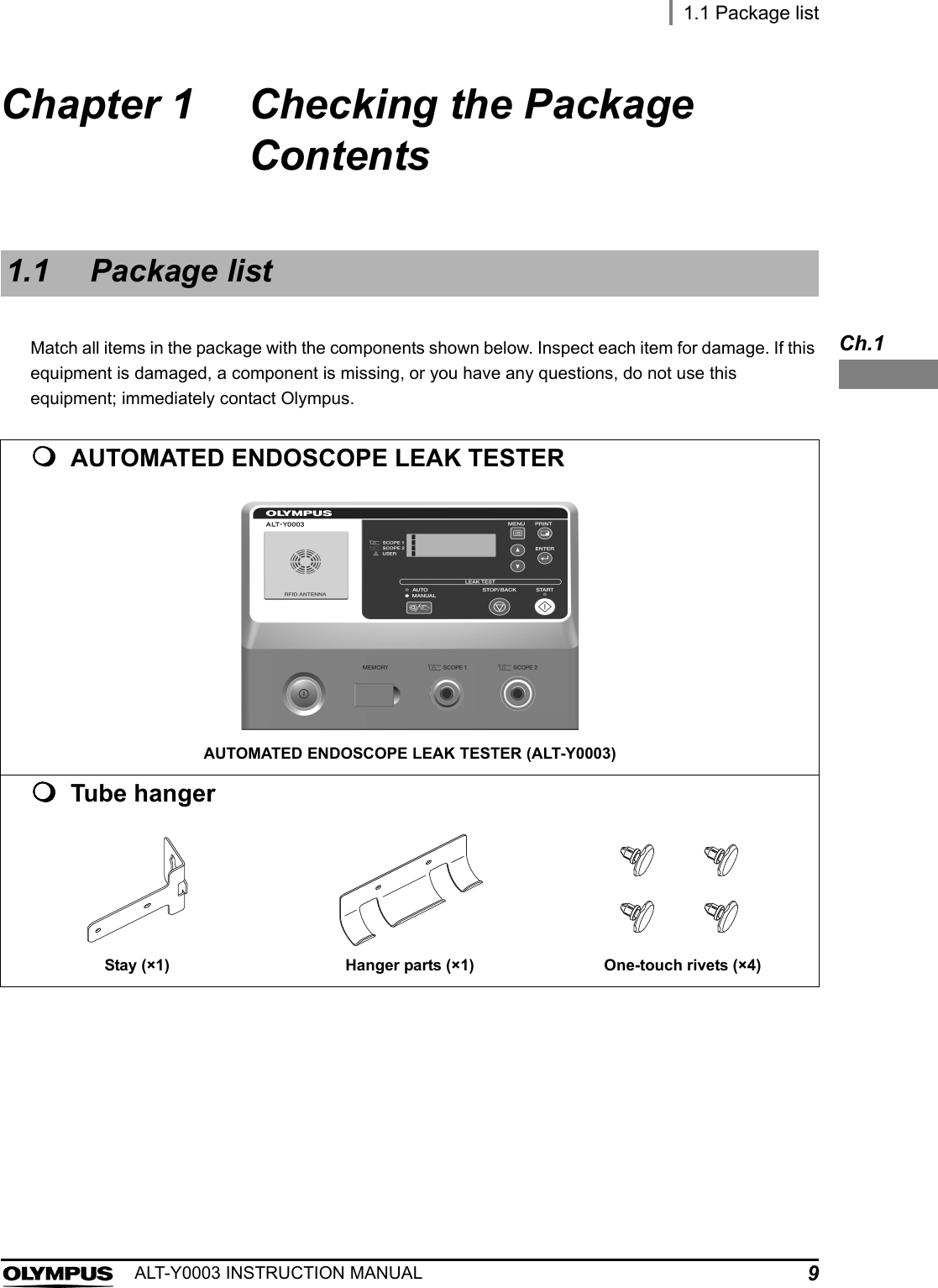
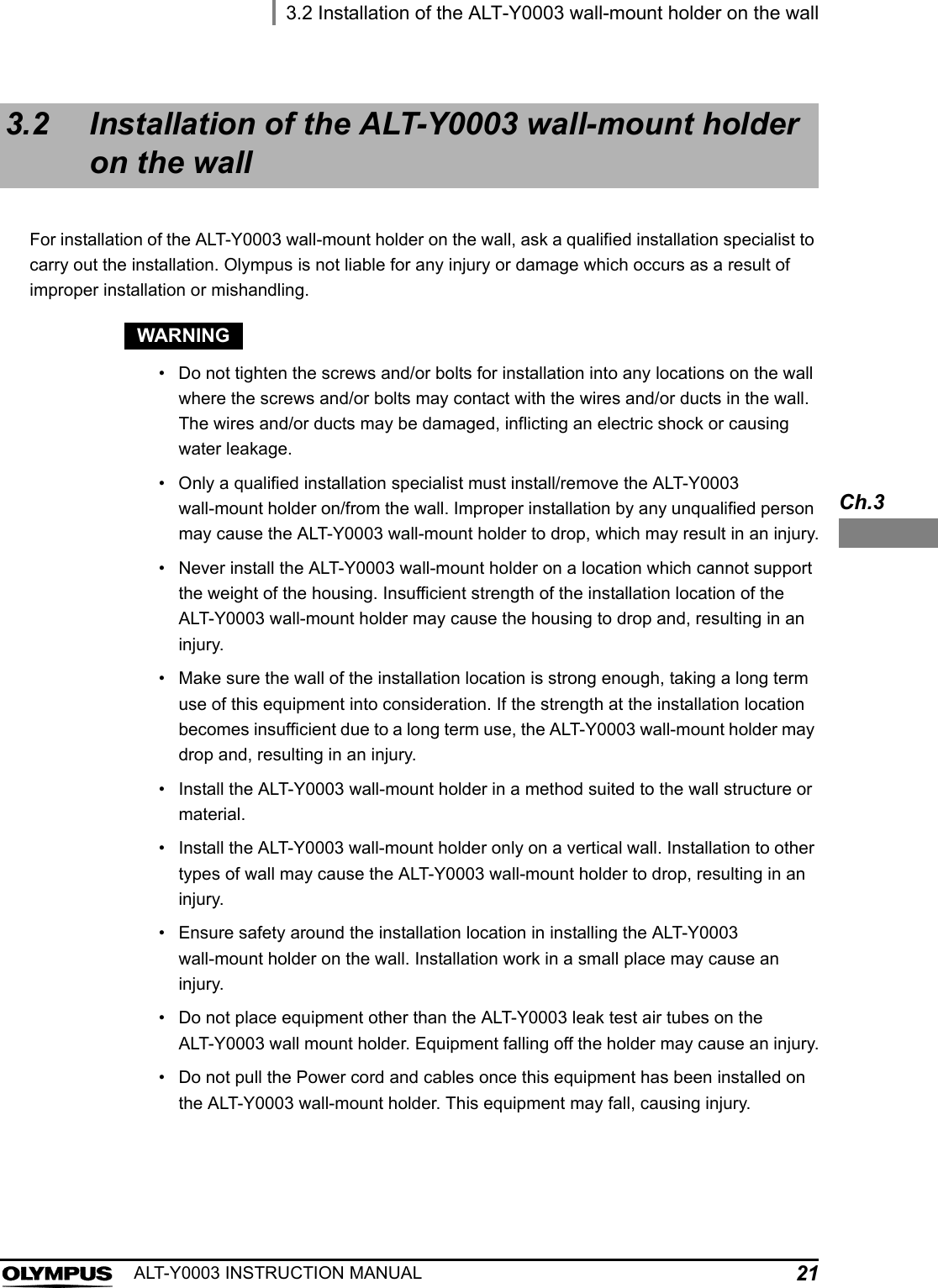
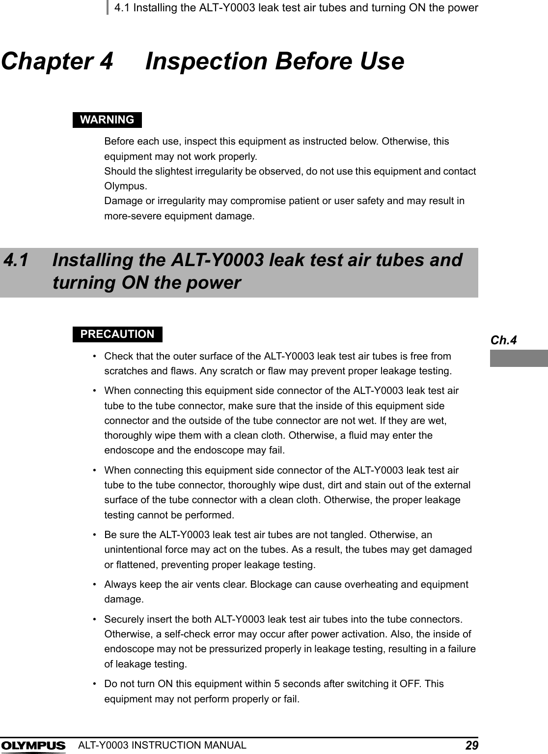
![5.4 Power activation39ALT-Y0003 INSTRUCTION MANUALCh.5NOTE• When the printer is used, turn ON the printer before turning ON this equipment.• For indicators on the printer after power activation, refer to Table 4.1 in Section 4.1, “Installing the ALT-Y0003 leak test air tubes and turning ON the power”.5.4 Power activation1Confirm that ALT-Y0003 leak test air tubes are surely connected to Tube connector 1 and 2 of this equipment. Also confirm that an endoscope or no water resistance caps are connected to the endoscope connectors of ALT-Y0003 leak test air tubes.NOTEAn error code [E112] is displayed on turning power ON if the ALT-Y0003 leak test air tubes are not securely connected to this equipment, or if an endoscope or water resistance cap is connected to the ALT-Y0003 leak test air tubes.2Turn the power switch ON.3A self-check start automatically.4A short beep sounds when the self-check is completed properly. As seen in Figure 5.1, the Scope ID indicator (SCOPE1) and User ID indicator (USER) indicators blink. The Standby screen is displayed on the LCD monitor.Figure 5.15ECP5EQRG+&ޓޓޓޓ1T7UGT+&=/'07?)QVQ/GPWSCOPE 1SCOPE 2USER](https://usermanual.wiki/Olympus-Medical-Systems/RU8354/User-Guide-1821797-Page-45.png)
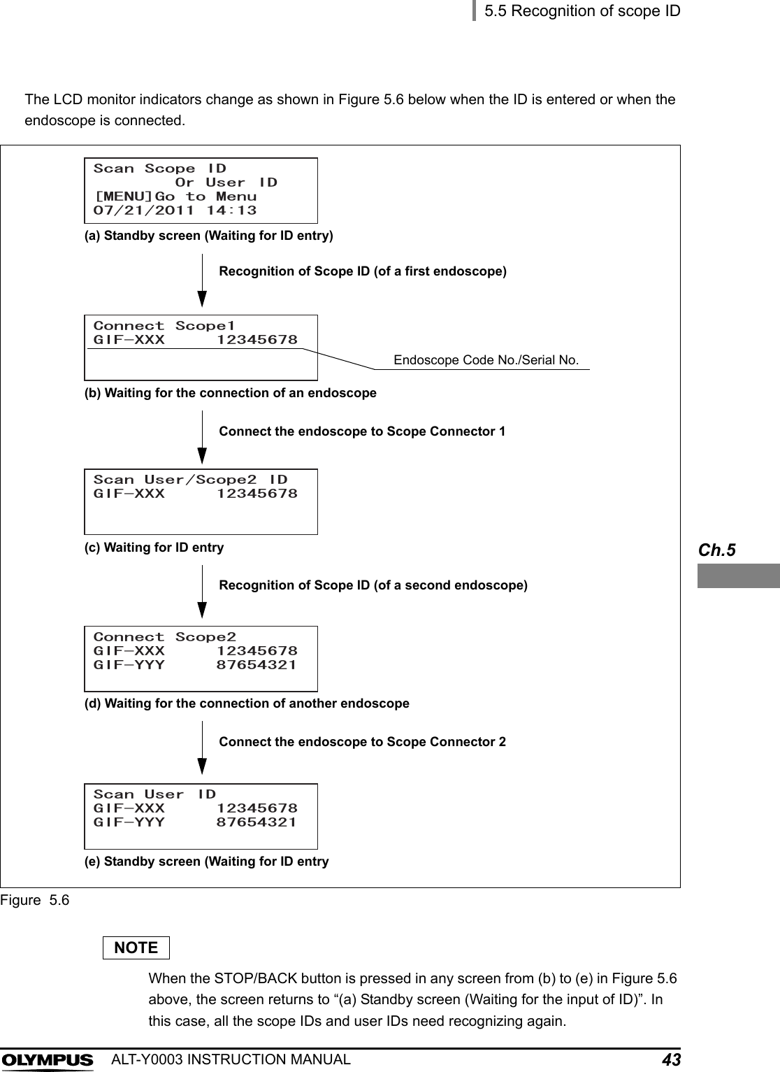
![5.5 Recognition of scope ID41ALT-Y0003 INSTRUCTION MANUALCh.51Confirm that ALT-Y0003 leak test air tubes are surely connected to Tube connector 1 and 2 of this equipment. Also confirm that an endoscope or no water resistance caps are connected to the endoscope connectors of ALT-Y0003 leak test air tubes.NOTEThe error code [E123] is displayed on the monitor when you try to read the scope with the following conditions:The ALT-Y0003 leak test air tubes is disconnected, orAn endoscope or water-resistant cap is connected to the ALT-Y0003 leak test air tubes2Bring the ID tag attached to the endoscope closer to the RFID reader of this equipment, and scan the tag with the reader until a short beep sounds.Figure 5.33Make sure that the Endoscope ID indicator “SCOPE 1” lights up on the control panel.Figure 5.4For internal ID-type endoscope For external ID tagSCOPE 1SCOPE 2USER](https://usermanual.wiki/Olympus-Medical-Systems/RU8354/User-Guide-1821797-Page-47.png)
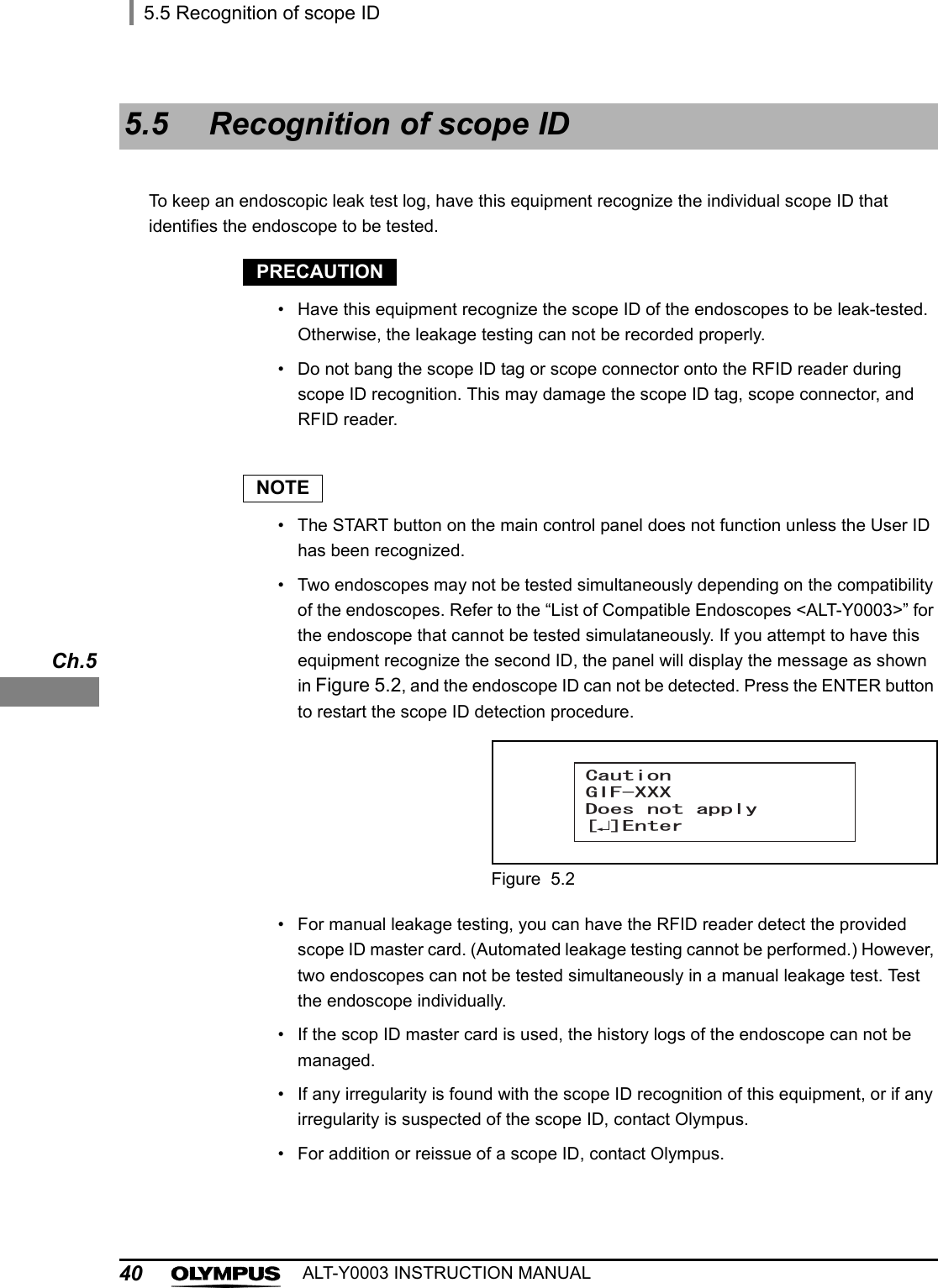
![425.5 Recognition of scope IDALT-Y0003 INSTRUCTION MANUALCh.5NOTE• When the first endoscope is detected, the Endoscope ID indicator “SCOPE 1” lights up.• When the second endoscope is detected, the Endoscope ID indicator “SCOPE 2” lights up.• To replace the endoscope to be tested, press the STOP/BACK button and disconnect the endoscope from the ALT-Y0003 leak test air tube. Go back to the beginning of Section 5.5 and repeat the steps.4Check that the Tube connector 1 indicator is blinking. Connect an endoscope to the ALT-Y0003 leak test air tube connected to Tube connector 1 according to the instruction described in Section 5.6, “Connecting ALT-Y0003 leak test air tubes and endoscope”.NOTEThe error code [E122] is displayed when, in the step 4 above, an endoscope is connected to the ALT-Y0003 leak test air tube that has been connected to Tube connector 2. Press the Enter button and detach the endoscope from the ALT-Y0003 leak test air tube. Go back to beginning of Section 5.5 and repeat the steps.Figure 5.55To leak test a second scope, repeat steps 1 – 4 above, and connect the second endoscope to the ALT-Y0003 leak test air tube connected to “Tube connector 2".](https://usermanual.wiki/Olympus-Medical-Systems/RU8354/User-Guide-1821797-Page-48.png)