Olympus Medical Systems RU8354 Automated Endoscope Leak Tester User Manual XGT8512 0100 fm10
Olympus Medical Systems Corp. Automated Endoscope Leak Tester XGT8512 0100 fm10
User Manual
INSTRUCTIONS
AUTOMATED ENDOSCOPE LEAK TESTER
ALT-Y0003
Labels and Symbols 1
Important Information — Please Read Before
Use 3
Summary of Functions of this Equipment 8
Chapter 1 Checking the Package Contents 9
Chapter 2 Nomenclature and Functions 11
Chapter 3 Installation and Connection 19
Chapter 4 Inspection Before Use 29
Chapter 5 Operation 35
Chapter 6 Routine Maintenance 57
Chapter 7 Other Functions 69
Chapter 8 Troubleshooting 93
Appendix 99

Contents
i
ALT-Y0003 INSTRUCTION MANUAL
Contents
Labels and Symbols .......................................................................................................... 1
Important Information — Please Read Before Use ......................................................... 3
Intended use .......................................................................................................................... 3
Instruction manual ................................................................................................................. 3
User qualifications ................................................................................................................. 4
Equipment compatibility ......................................................................................................... 4
Care and storage ................................................................................................................... 5
Maintenance and inspection .................................................................................................. 5
Repair and modification ......................................................................................................... 5
Disposal of this equipment .................................................................................................... 5
Signal words .......................................................................................................................... 5
Warnings and precautions ..................................................................................................... 6
Summary of Functions of this Equipment ...................................................................... 8
Chapter 1 Checking the Package Contents ......................................... 9
1.1 Package list ............................................................................................................... 9
Chapter 2 Nomenclature and Functions ............................................ 11
2.1 Front panel .............................................................................................................. 11
2.2 Control panel .......................................................................................................... 12
2.3 Rear panel ............................................................................................................... 13
2.4 ALT-Y0003 leak test air tube MAJ-2009 ................................................................ 14
2.5 Printer MAJ-1937 (optional) ................................................................................... 15
2.6 ALT-Y0003 interface cable MAJ-2052 (Optional) ................................................. 17
2.7 Portable memory MAJ-1925 (Optional) ................................................................ 18
2.8 ALT-Y0003 wall-mount holder (Optional) ............................................................. 18
Chapter 3 Installation and Connection ............................................... 19
3.1 Installation of this equipment ................................................................................ 19
3.2 Installation of the ALT-Y0003 wall-mount holder on the wall ............................. 21
3.3 Installation of the tube hanger .............................................................................. 24
3.4 Connecting the Power Supply .............................................................................. 26
3.5 Connecting the printer ........................................................................................... 27

ii
Contents
ALT-Y0003 INSTRUCTION MANUAL
Chapter 4 Inspection Before Use ........................................................ 29
4.1 Installing the ALT-Y0003 leak test air tubes and turning ON the power ............ 29
4.2 Self-check ................................................................................................................ 32
If the error code [E112] is displayed during self-check ........................................................ 33
4.3 Checking the printer paper roll ............................................................................. 34
Chapter 5 Operation ............................................................................. 35
5.1 Precautions for operation ...................................................................................... 35
5.2 Operation workflow ................................................................................................ 37
5.3 Preparation before use ........................................................................................... 38
5.4 Power activation ..................................................................................................... 39
5.5 Recognition of scope ID ........................................................................................ 40
5.6 Connecting ALT-Y0003 leak test air tubes and endoscope ................................ 44
5.7 Recognition of user ID ........................................................................................... 46
5.8 Automated leakage testing .................................................................................... 47
The results in the automated leakage testing are all PASS: ................................................ 50
If the result of leakage testing for at least one endoscope is FAIL ...................................... 51
5.9 Manual leakage testing .......................................................................................... 52
Chapter 6 Routine Maintenance .......................................................... 57
6.1 Summary ................................................................................................................. 57
6.2 Care of ALT-Y0003 leak test air tubes ................................................................... 58
When any debris remains on the surface ............................................................................ 59
When no debris remains on the surface .............................................................................. 60
6.3 Turning power OFF and cleaning outer surface .................................................. 61
6.4 Installing the printer paper roll .............................................................................. 62
6.5 Replacing the fuse .................................................................................................. 65
6.6 Storage .................................................................................................................... 67

Contents
iii
ALT-Y0003 INSTRUCTION MANUAL
Chapter 7 Other Functions .................................................................. 69
7.1 Setting date ............................................................................................................. 69
7.2 Setting time ............................................................................................................. 70
7.3 Performing only self-check ................................................................................... 71
7.4 Setting automated leakage test mode .................................................................. 72
7.5 Setting print mode .................................................................................................. 74
Manual printing .................................................................................................................... 75
Auto Print ............................................................................................................................. 80
When the error code [E094] is displayed during printing ..................................................... 81
7.6 Data display ............................................................................................................ 82
Leak Test Log Display ......................................................................................................... 82
Error Log Display ................................................................................................................. 84
7.7 Download to a portable memory ........................................................................... 85
Downloading data ................................................................................................................ 87
Formatting the portable memory .......................................................................................... 89
7.8 Management of portable memory data in personal computer ........................... 90
Folder structure ................................................................................................................... 91
Chapter 8 Troubleshooting .................................................................. 93
8.1 Troubleshooting guide ........................................................................................... 93
8.2 Return of this equipment for repair ...................................................................... 98
Appendix ................................................................................................. 99
Compatible equipments .................................................................................................. 99
System chart ........................................................................................................................ 99
Specification .................................................................................................................. 101
Environment ...................................................................................................................... 101
Specifications ..................................................................................................................... 101
EMC information ............................................................................................................ 103

iv
Contents
ALT-Y0003 INSTRUCTION MANUAL
Labels and Symbols
1
ALT-Y0003 INSTRUCTION MANUAL
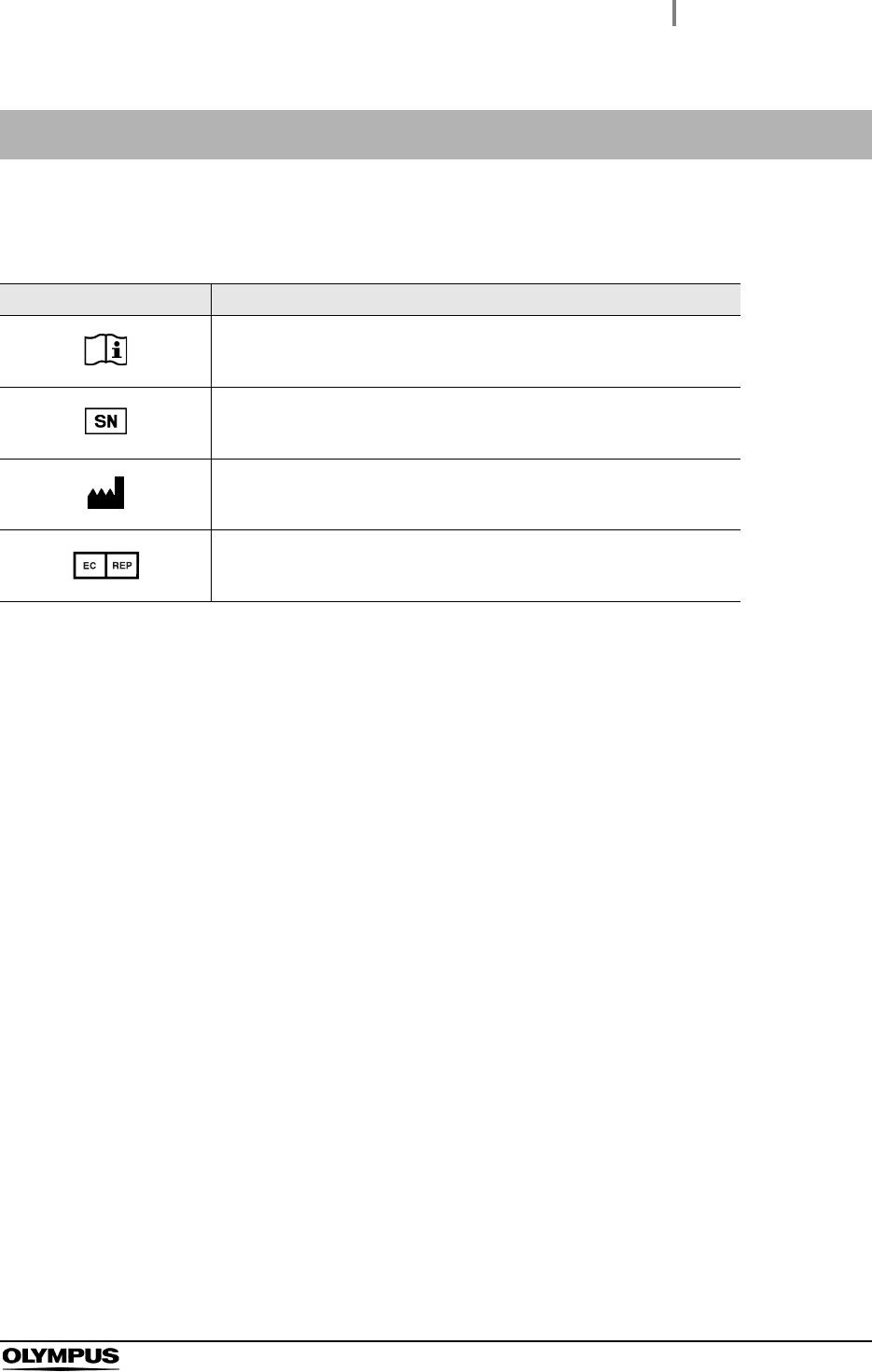
The meaning(s) of the symbol(s) shown on the component packaging, the back cover of this instruction
manual and/or this equipment are as follows:
Labels and Symbols
Symbol Description
Refer to instructions.
Serial number
Manufacturer
Authorized representative in the European Community
2
Labels and Symbols
ALT-Y0003 INSTRUCTION MANUAL
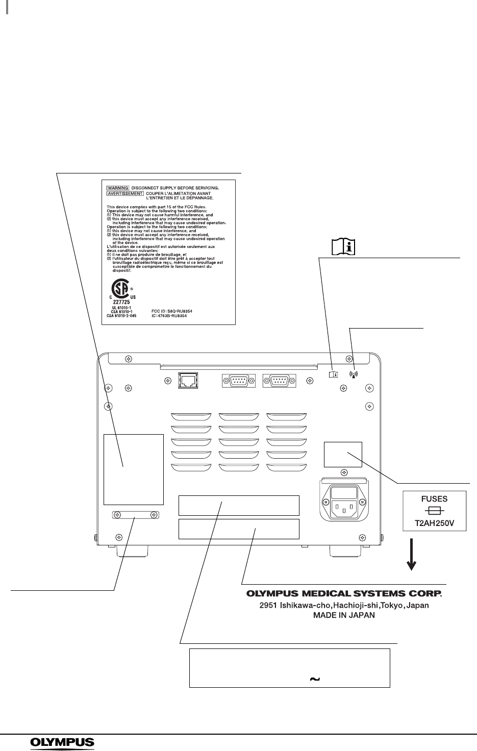
Safety-related labels and symbols are attached to this equipment at the locations shown below. If
labels or symbols are missing or illegible, contact Olympus.
Rear panel
Manufacturer name
RFID marking
Fuse rating
Serial number plate
Indicates to see the instruction
manual for the cable to be
connected.
AUTOMATED ENDOSCOPE LEAK TESTER
MODEL ALT-Y0003
POWER INPUT 100–120 V 50/60 Hz 45 VA
Electric rating
CSA/UL marking

Important Information — Please Read Before Use
3
ALT-Y0003 INSTRUCTION MANUAL
Intended use
This equipment is intended to be used to perform and record leakage testing on Olympus flexible
endoscopes. Do not use this AUTOMATED ENDOSCOPE LEAK TESTER for any purpose other than
its intended use.
Instruction manual
This instruction manual contains essential information on using this AUTOMATED ENDOSCOPE
LEAK TESTER (hereinafter referred to as “this equipment”) safely and effectively. Before use,
thoroughly review this manual and the manuals of all equipment which will be used during the
procedure, and use all equipment as instructed.
Keep this and all related instruction manuals in a safe, accessible location.
If you have any questions or comments about any information in this manual, please contact Olympus.
Terms used in this manual
Leakage Test
A leakage test can detect a pin hole in the external surface of the endoscope and/or
internal working channel wall, and any other leak-related damage.
When the endoscope is immersed in a liquid for cleaning and disinfection, the liquid may
go into the endoscope through a pin hole or other damaged area, resulting in malfunction
of electrical components inside the endoscope. Detecting such a pin hole and damaged
area before liquid immersion of the endoscope can prevent potential damage of the
endoscope caused by the entry of the liquid into the endoscope.
Process
A general term for the leakage testing, self-check, and other operations this Equipment
performs.
Portable Memory
Olympus-designated USB memory: This recording medium is used in combination with
this equipment to save leakage test data stored in the internal memory of this equipment.
Master data
These are unedited leak test log data and error log data copied to personal computers.
Important Information — Please Read Before Use

4
Important Information — Please Read Before Use
ALT-Y0003 INSTRUCTION MANUAL
CSV file format
This is one data format most frequently used by statistical processing software. Each
item of data (record) is accommodated in a single line, in which each item is delimited
by “,” (a comma). This data is useful when executing statistical processing using
commercially available statistical processing software.
Wall mains outlet:
A three-pin outlet having an exclusive terminal for grounding.
Error Code
A code consisting of [E] and a three-digit number is displayed on the LCD monitor, if there
is a problem with this equipment. When an error code is displayed, check the error code
list to find out what corrective measures to take.
User qualifications
The operator of this equipment must be sufficiently trained in reprocessing of endoscopes. The
medical literature reports cases of infections due to inappropriate cleaning, disinfection, and /or
sterilization. Thoroughly review and understand the following items before use:
Cleaning, disinfection, and sterilization procedures described in the instruction manuals for
the endoscope and ancillary equipment
Professional health and safety standards
Applicable guidelines on cleaning, disinfection, and sterilization of endoscopy equipment.
Structure and handling of endoscopic equipment
Personal protective equipment requirements to minimize exposure to chemicals and
infectious materials.
This manual does not explain or discuss details of cleaning, disinfection, and sterilization.
Equipment compatibility
Use this equipment in combination with ancillary equipment listed in System Chart in Appendix. Using
incompatible equipment can result in patient or operator injury and equipment damage and/or
malfunction. Refer to the “List of Compatible Endoscopes <ALT-Y0003>” for compatible types of
endoscope.
Do not use this equipment in combination with non-Olympus endoscopes; Olympus has not tested the
efficacy of detecting leakage with this equipment other than those combinations designated.
Important Information — Please Read Before Use
5
ALT-Y0003 INSTRUCTION MANUAL
Care and storage
After use, reprocess and store this equipment referring to the instructions in Chapter 6, “Routine
Maintenance” in this manual. Inappropriate care and storage could present an infection control risk
and/or cause equipment damage or malfunction.
Maintenance and inspection
The ALT-Y0003 requires routine maintenance and inspection. In addition to checks before use, the
person in charge of maintenance and administration of the medical equipment at the hospital should
periodically check all of the items described in this manual. If any irregularity is observed, do not use
this equipment and follow the procedure as described in Section 8.1, “Troubleshooting guide”. If the
irregularity still presents, this equipment needs repairing. Contact Olympus.
Repair and modification
Do not disassemble, modify or attempt to repair this equipment and its accessories. Doing so could
result in operator or patient injury and/or equipment damage or malfunction. Some problems that
appear to be malfunctions may be corrected by referring to Section 8.1, “Troubleshooting guide”. If the
problem persists, do not use this equipment and contact Olympus.
Disposal of this equipment
Follow all applicable national and local guidelines in disposing of this equipment.
Signal words
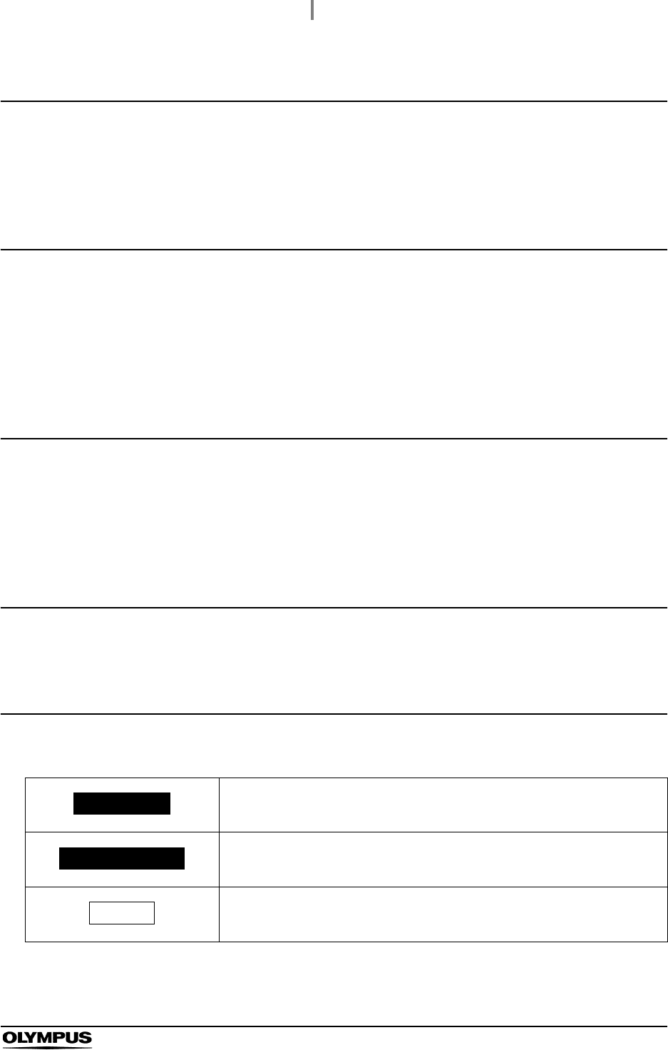
The following signal words are used throughout this manual:
Describes serious adverse reactions and potential safety hazards, limitations
in use imposed by them, and steps that should be taken if they occur.
Includes information regarding any special care to be exercised by the
practitioner and/or patient for the safe and effective use of the device.
Indicates additional helpful information.
WARNING
PRECAUTION
NOTE

6
Important Information — Please Read Before Use
ALT-Y0003 INSTRUCTION MANUAL
Warnings and precautions
Follow the warnings and precautions given below when handling this equipment. This information is
supplemented by the warnings given in each chapter.
WARNING
• Strictly observe the following precautions. Failure to do so may place the patient
and medical personnel in danger of an electric shock.
Keep fluids away from all electrical equipments. If fluids are spilled on or into
this equipment, stop operation immediately and contact Olympus.
Do not prepare, inspect, or use this equipment with wet hand
• Do not install this equipment in any place where any of the following are present.
High oxygen concentration.
Oxidizing substance such as Nitrous Oxide (N2O).
Flammable anesthetic gas
Flammable liquid
This equipment is not explosion-proof and may explode or cause fire under these
conditions.
• Do not insert an EndoTherapy accessory or other object through an opening
including the air vents of this equipment. Also, do not allow any liquid including
water or disinfectant solution to flow into the opening. Contact with an electrical part
inside this equipment could cause an electric shock and/or malfunction of this
equipment.
• This equipment may interfere with other medical electronic equipment used in
combination with it. Before use, refer to the Appendix to confirm the compatibility of
this equipment with all equipment to be used.
• Always use the Power cord provided with this equipment. Otherwise, equipment
failure or Power cord burnout could result. Also, remember that the provided Power
cord is for exclusive use with this equipment and should not be used with other
equipment.
• Do not bend, pull or twist the power cord. Electric shock, equipment damage, or fire
can result.
• This equipment can be set up to use the RFID (Radio Frequency Identification)
function. Please be aware that the radio waves emitted from the RFID antenna of
this equipment may cause medical equipments such as pacemakers to
malfunction. If any interference with this equipment is observed, immediately move
away from the RFID antenna or set the power switch to OFF. Call your doctor if you
do not begin to feel better.

Important Information — Please Read Before Use
7
ALT-Y0003 INSTRUCTION MANUAL
PRECAUTION
• Certain endoscopes cannot be leak-tested automatically in this equipment. Refer to
the “List of Compatible Endoscopes <ALT-Y0003>” provided with this equipment.
• Do not use this equipment in any place where it may be subject to strong
electromagnetic radiation (for example, in the vicinity of a microwave therapeutic
equipment, short wave medical treatment equipment, MRI, and cellular/portable
phone, etc). Doing so may result in malfunction of this equipment.
• Do not press the buttons on the front panel of this equipment with a sharp or hard
object. Doing so may damage the buttons.
• Avoid applying excessive force to the connectors, as this may damage this
equipment.
• Do not use this equipment in a dusty environment. Otherwise, damage and/or
malfunction can occur.
• Be sure that this equipment is not used adjacent to other equipments (other than
the components of this equipment or system) to avoid electromagnetic
interference.
• Be sure that this equipment is not used adjacent to or stacked with other
equipment. An external force applied to this equipment may result in damage and
deformation.
• This equipment emits RF (Radio Frequency) energy to perform intended functions.
Therefore, it may cause electromagnetic interference in nearby electronic
equipment, and is labeled with the following symbol. If electromagnetic interference
occurs, mitigation measures may be necessary, such as moving the electronic
equipment away, reorienting or relocating this instrument, or shielding the location.

8
Summary of Functions of this Equipment
ALT-Y0003 INSTRUCTION MANUAL
Automated Leakage Testing (ALT)
This equipment feeds air into the endoscope and computes changed air pressure to check
automatically for a pin hole of the endoscope. The Automated Leakage Testing is performed in
air, not in water.
See Section 5.8, “Automated leakage testing”.
Manual Leakage Testing (MLT)
This equipment feeds air into the endoscope to visually check for any bubble emerging from the
endoscope in water.
See Section 5.9, “Manual leakage testing”.
Self-check
This equipment has a self-check function to verify that it is working properly.
See Section 4.2, “Self-check”.
Printing
The results of leakage tests and self-checks and the records of errors can be printed from a
connected printer.
See Section 7.5, “Setting print mode”.
Data download
The results of leakage tests and self-checks and the records of errors can be downloaded to a
portable memory.
See Section 7.7, “Download to a portable memory”.
Summary of Functions of this Equipment
1.1 Package list
9
ALT-Y0003 INSTRUCTION MANUAL
Ch.1
Chapter 1 Checking the Package
Contents
Match all items in the package with the components shown below. Inspect each item for damage. If this
equipment is damaged, a component is missing, or you have any questions, do not use this
equipment; immediately contact Olympus.
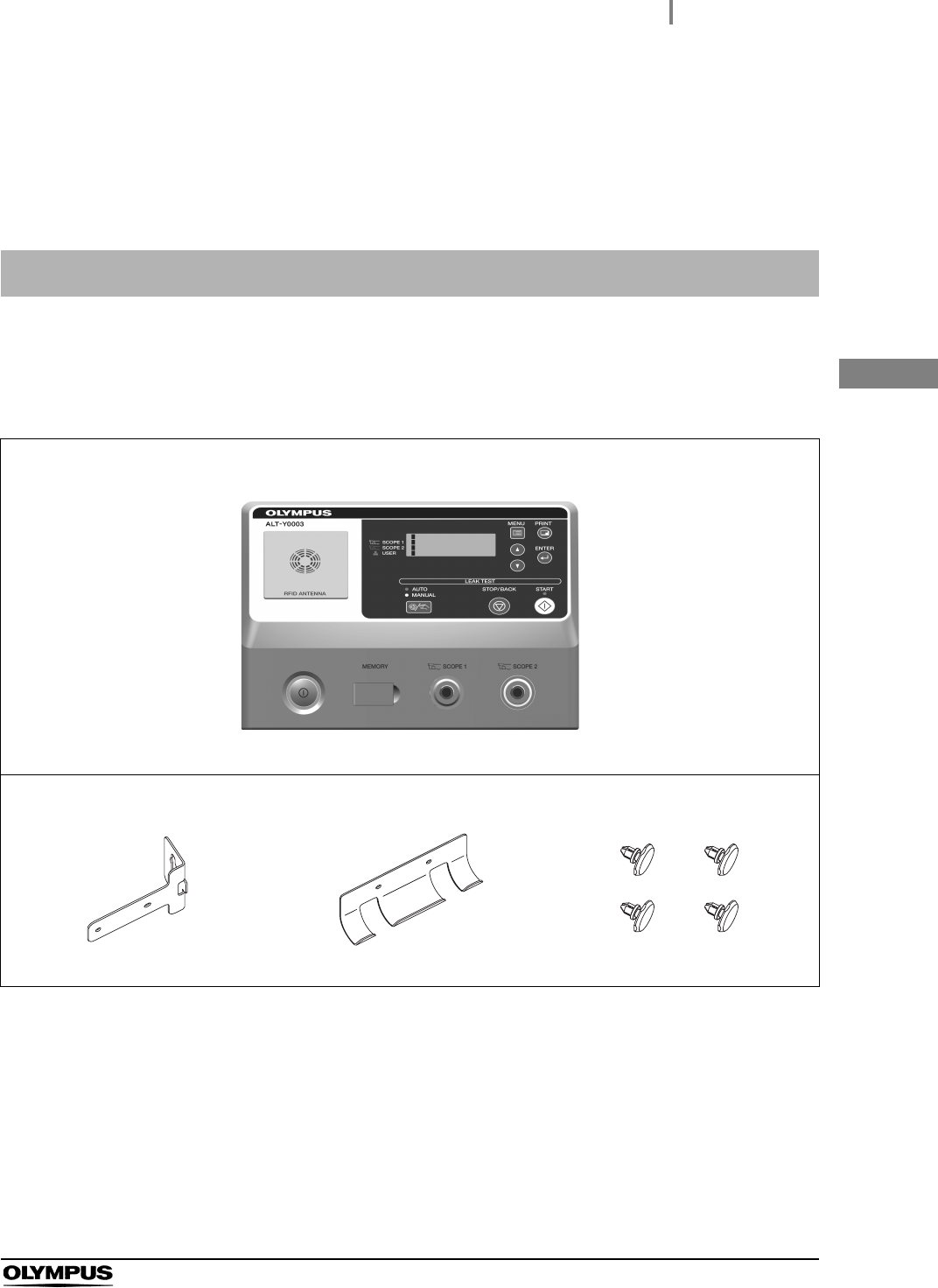
1.1 Package list
AUTOMATED ENDOSCOPE LEAK TESTER
AUTOMATED ENDOSCOPE LEAK TESTER (ALT-Y0003)
Tube hanger
Stay (×1) Hanger parts (×1) One-touch rivets (×4)
10
1.1 Package list
ALT-Y0003 INSTRUCTION MANUAL
Ch.1
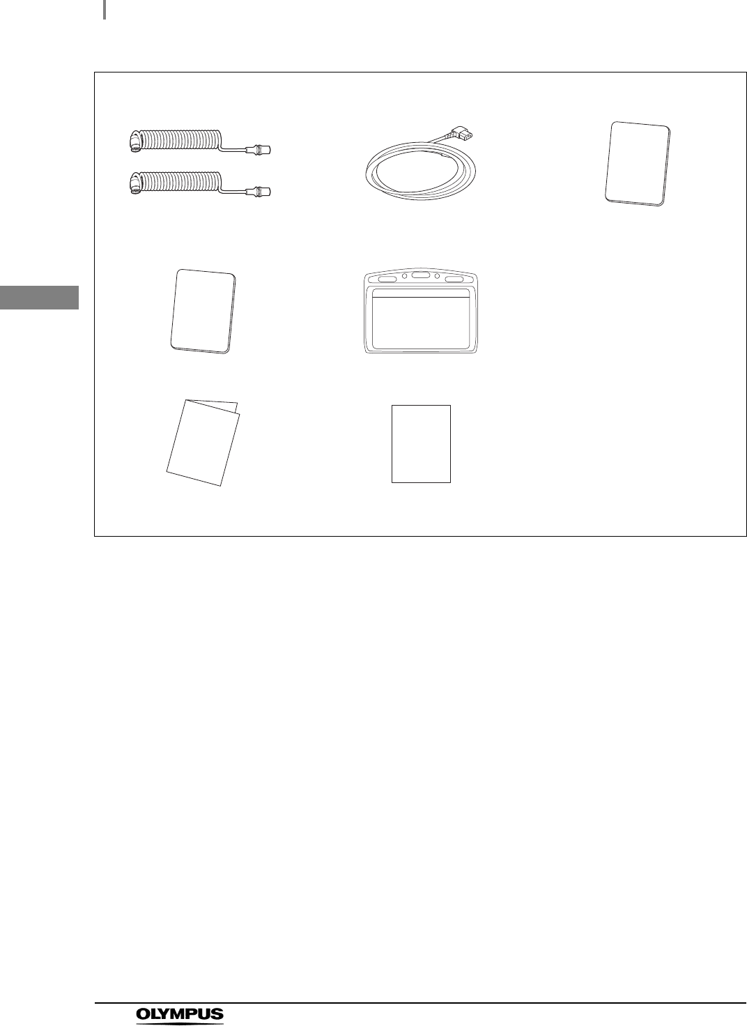
Accessories
ALT-Y0003 leak test air tubes (×2)
(MAJ-2009)
Power cord User ID master card
Scope ID master card Card holders (×2)
Instruction manual List of Compatible Endoscopes
<for ALT-Y0003>
2.1 Front panel
11
ALT-Y0003 INSTRUCTION MANUAL
Ch.2
Chapter 2 Nomenclature and
Functions
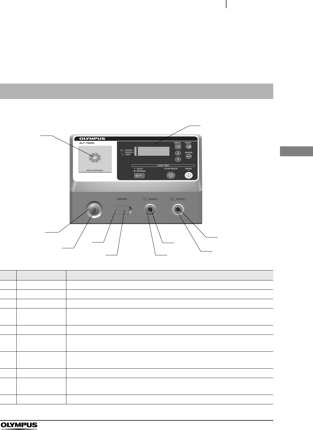
2.1 Front panel
No. Name Description
1 RFID reader Reads user IDs and scope IDs into this equipment
2 CONTROL PANEL Used to control and set up this equipment.
3 Tube connector 2 Accepts the ALT-Y0003 leak test air tube
4 Tube connector 2
indicator
Blinks when the scope ID has been recognized and then lights when the scope has
been connected to the ALT-Y0003 leak test air tube.
5 Tube connector 1 Accepts the ALT-Y0003 leak test air tube
6 Tube connector 1
indicator
Blinks when the scope ID has been recognized and then lights when the scope has
been connected to the ALT-Y0003 leak test air tube.
7 Portable memory
port
Accepts an (optional) portable memory.
8 Memory port cap The cap to protect the portable memory port.
9 Power switch Press to switch the power ON/OFF. The green light is lit when this equipment is turned
ON.
10 Power indicator Lights up when electric power is supplied.
1
2
3
4
5
6
7
8
9
10
12
2.2 Control panel
ALT-Y0003 INSTRUCTION MANUAL
Ch.2
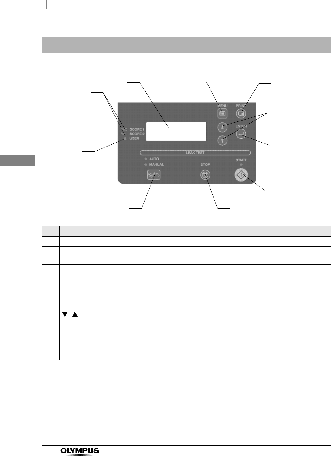
2.2 Control panel
No. Name Description
1 User ID indicator Lights up when the user ID is recognized.
2 Endoscope ID
indicator
Lights up when the scope ID is recognized.
3 LCD monitor Displays the test process and results.
4 MENU button In the standby state, the function menus can be displayed on the LCD monitor by
pressing the button.
5 PRINT button In the standby state, the printing menus can be displayed on the LCD monitor by
pressing the button.
6,
button Press these buttons to set the program, time and date.
7 ENTER button Pressed to confirm the end of the process and settings.
8 START button Pressed this button to start the selected program.
9 STOP/BACK button Pressed this button to interrupt the test procedure or cancel settings.
10 SELECT button Pressed this button to select ALT or MLT.
2
5
6
7
34
1
10
8
9
2.3 Rear panel
13
ALT-Y0003 INSTRUCTION MANUAL
Ch.2
PRECAUTION
Never touch the pin inside the printer terminal and option terminal. Static electricity
may cause a malfunction or damage of this equipment.
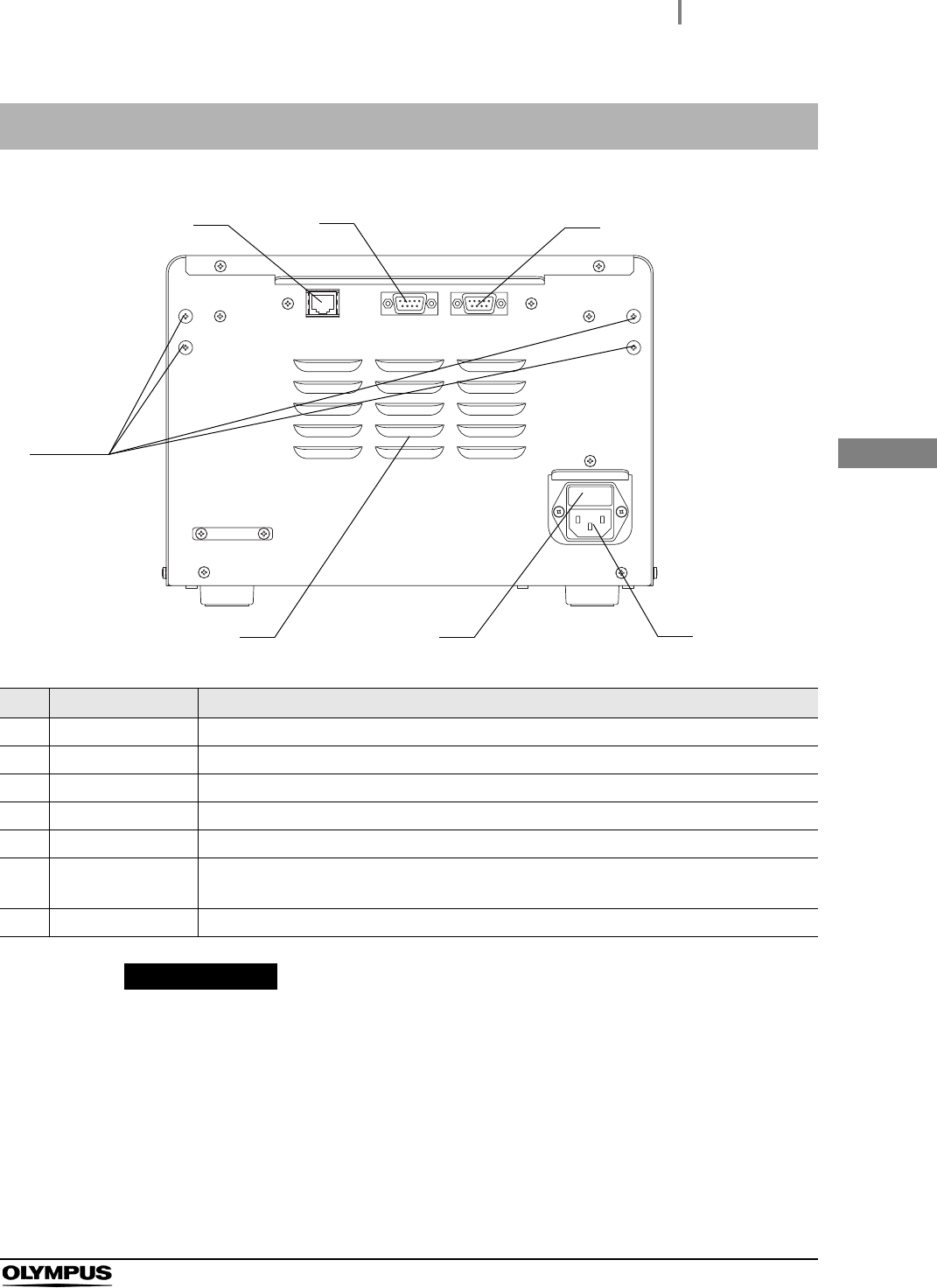
2.3 Rear panel
No. Name Description
1 LAN Connector This terminal is provided for future function extension and cannot be used currently.
2 Option terminal Not used. (A terminal only for service persons.)
3 Printer terminal Use the ALT-Y0003 interface cable to connect the printer to this equipment.
4 AC Inlet Accepts AC power supply
5 Fuse box Contains a fuse for this equipment.
6 Air vent Draws in fresh air from the room, not into the room, and prevents the temperature from
rising in this equipment.
7 Projections Fixture for mounting the tubing hanger.
3
12
4
56
7
14
2.4 ALT-Y0003 leak test air tube MAJ-2009
ALT-Y0003 INSTRUCTION MANUAL
Ch.2
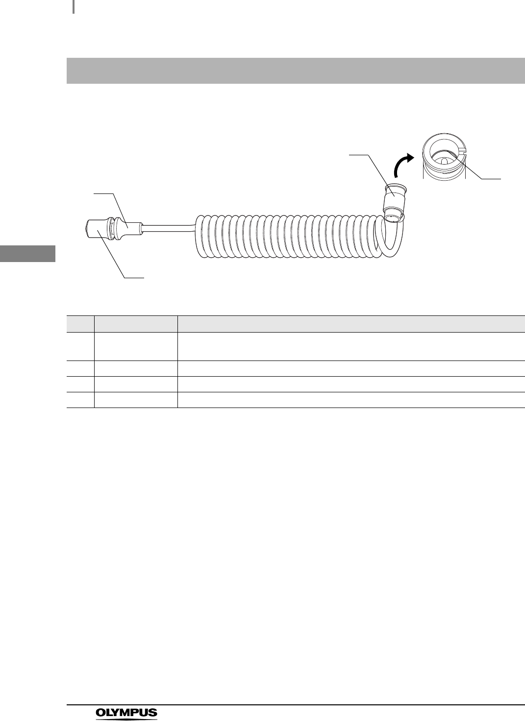
2.4 ALT-Y0003 leak test air tube MAJ-2009
No. Name Description
1 Endoscope side
connector
Connected to the venting connector of Olympus endoscope or water-resistant cap.
2 O-ring (Black) Rubber to keep the ALT-Y0003 leak test air tube airtight.
3 Connecting grip Held to connect the ALT-Y0003 leak test air tube to this equipment.
4 Removing grip Held to remove the ALT-Y0003 leak test air tube from this equipment.
4
2
1
3
2.5 Printer MAJ-1937 (optional)
15
ALT-Y0003 INSTRUCTION MANUAL
Ch.2
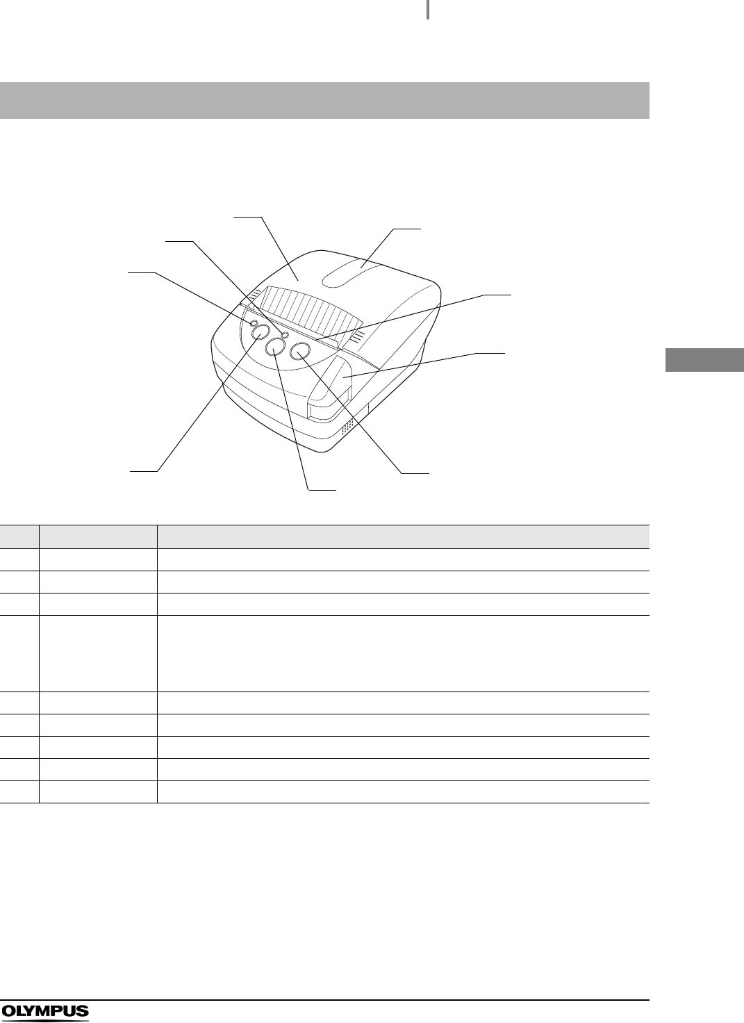
Front Panel
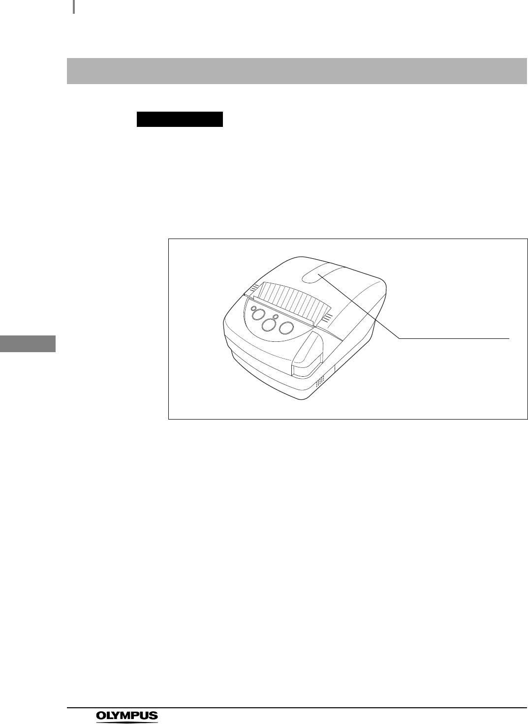
2.5 Printer MAJ-1937 (optional)
No. Name Description
1 ERROR LED Indicates printer errors
2 POWER LED Indicates Power On and Off
3 Paper cover Stores paper under this cover
4 Transparent
window to check
the printer paper
roll
Check through this transparent window whether the paper is set or how much it remains
5 Paper cutter Pull the paper toward you to cut paper.
6 Cover open button Pressed to open the paper cover when the paper roll is set.
7 FEED button Pressed to feed the printer paper roll
8 POWER button Pressed to turn this equipment ON and OFF
9 SELECT button No used
1
4
5
6
2
3
7
8
9
16
2.5 Printer MAJ-1937 (optional)
ALT-Y0003 INSTRUCTION MANUAL
Ch.2
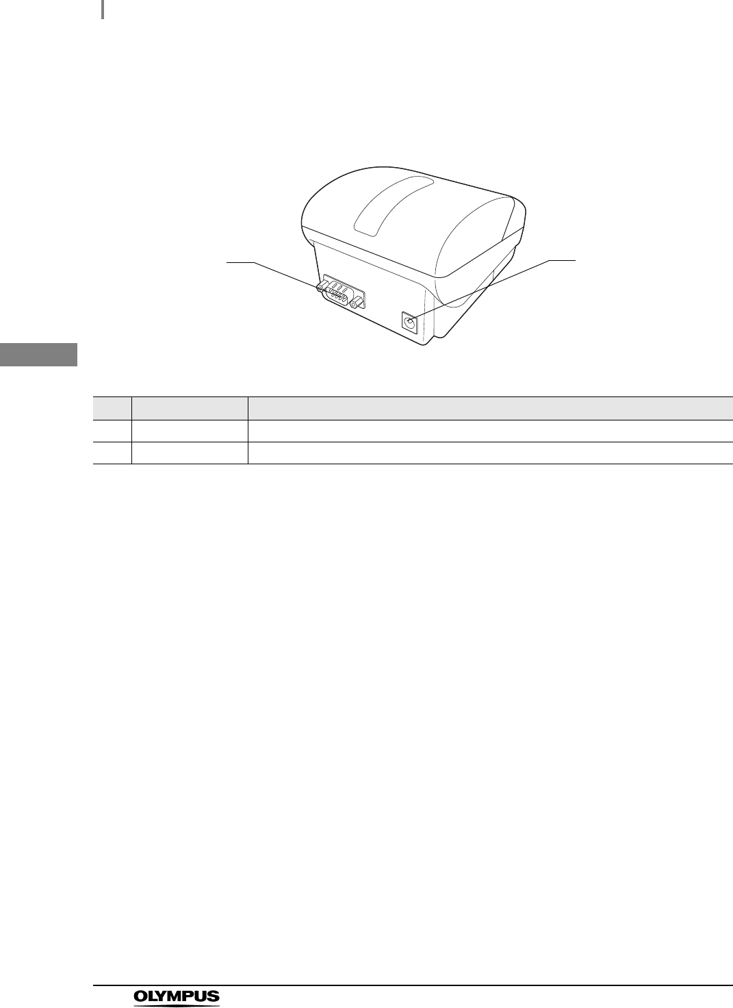
Rear panel
No. Name Description
1 IF Connector Accepts the ALT-Y0003 interface cable
2 AC Power Inlet Accepts the exclusive power cord.
2
1
2.6 ALT-Y0003 interface cable MAJ-2052 (Optional)
17
ALT-Y0003 INSTRUCTION MANUAL
Ch.2
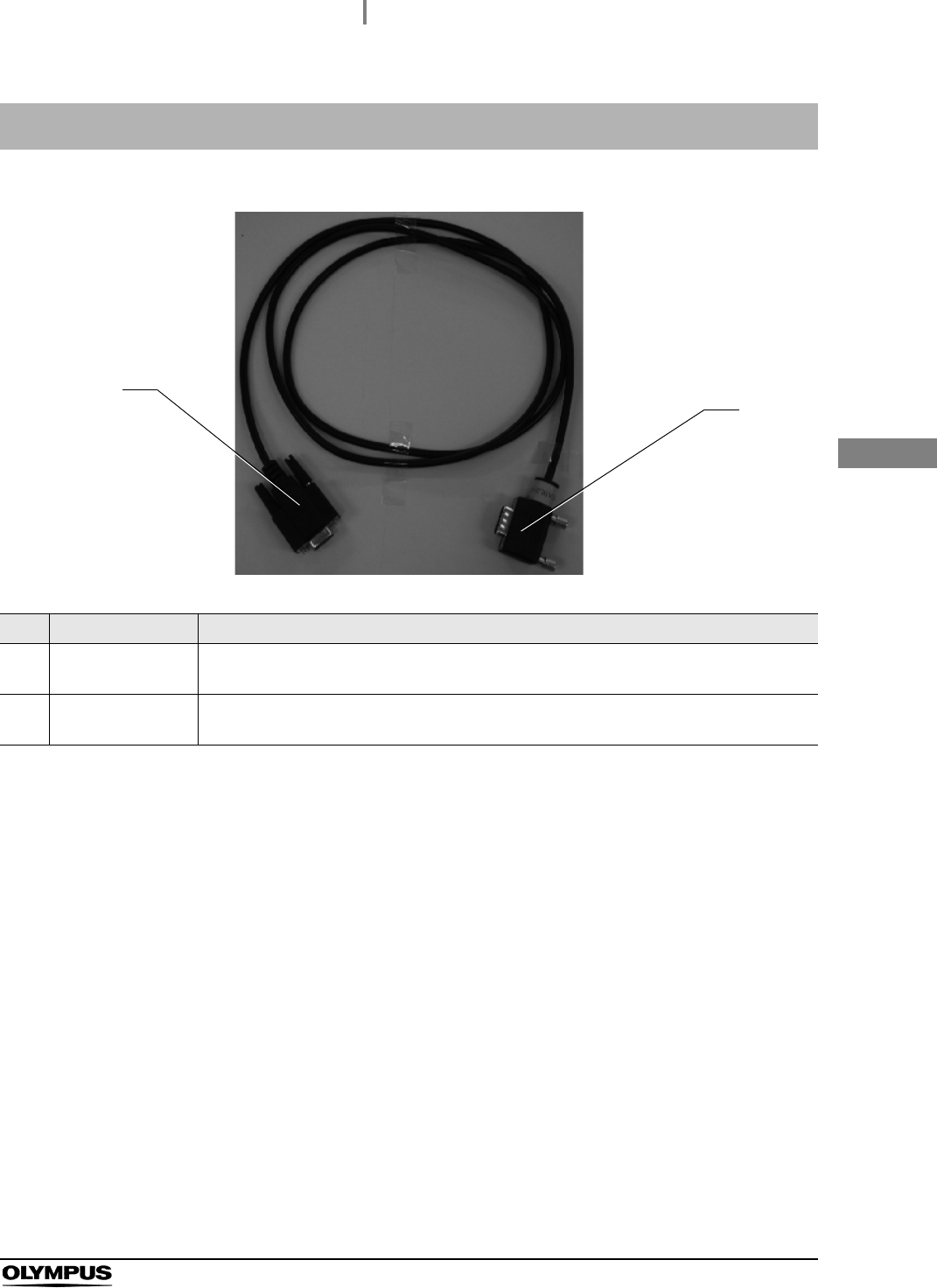
* The ALT-Y0003 interface cable is 1.5 m long.
2.6 ALT-Y0003 interface cable MAJ-2052 (Optional)
No. Name Description
1 Printer side
connector
Accepts the IF connector of the printer.
2 Equipment side
connector
Accepts the printer terminal of this equipment.
2
1
18
2.7 Portable memory MAJ-1925 (Optional)
ALT-Y0003 INSTRUCTION MANUAL
Ch.2
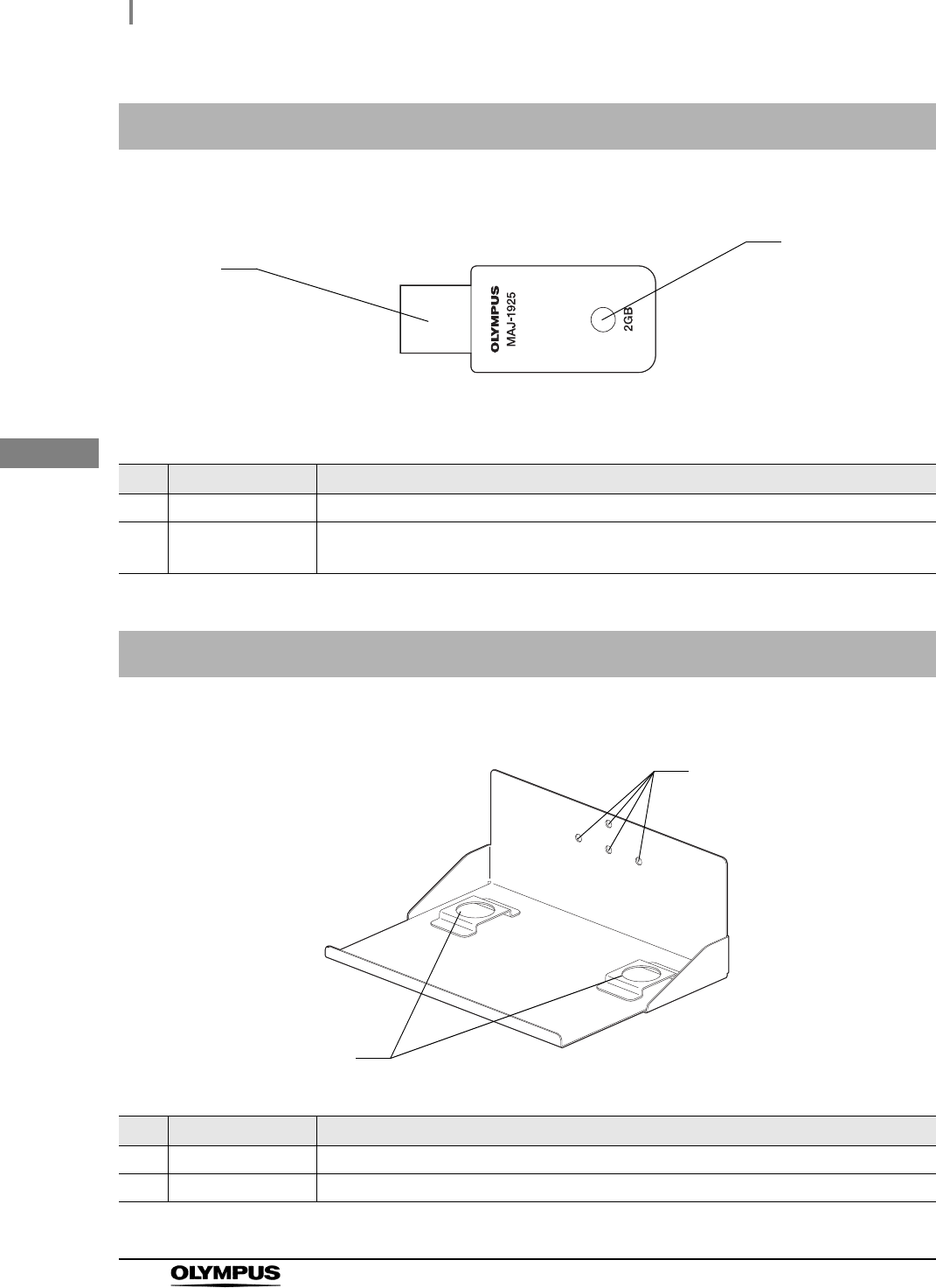
2.7 Portable memory MAJ-1925 (Optional)
No. Name Description
1 Connector Insert the connector into the Portable memory port.
2 LED The LED is blinking while the endoscopic images, patient data, and setting information
are saved or read.
2.8 ALT-Y0003 wall-mount holder (Optional)
No. Name Description
1 Mounting holes Holes for screws to fix the ALT-Y0003 wall mount holder to a wall.
2 Foot base Accepts the feet of ALT-Y0003.
2
1
2
1

3.1 Installation of this equipment
19
ALT-Y0003 INSTRUCTION MANUAL
Ch.3
Chapter 3 Installation and Connection
This equipment is not water-proof. Install this equipment referring to the following instillation conditions.
Use of the ALT-Y0003 wall-mount holder (MAJ-2020) (Optional) enables you to install this equipment
on the wall. To mount this equipment on the wall, refer to Section 3.2, “Installation of the ALT-Y0003
wall-mount holder on the wall” in this instruction manual.
WARNING
• Do not spray water on this equipment. Otherwise, a short occurs in the internal
circuit, resulting in an electric shock or fire.
• Check the location of this equipment to see if it is within 2 m away from the location
of the endoscope where an air leak test is performed (the sink or basin). Pulling the
ALT-Y0003 leak test air tubes may topple this equipment to fall, resulting in injury.
• Do not use a humidifier near this instrument. Dew condensation may occur inside
this equipment, causing a malfunction.
PRECAUTION
• Do not place this equipment on its side or upside down.
• Keep the air vents of this equipment clear. The air vents are on the back panels.
Blockage can cause overheating and equipment damage.
• In installing this equipment, taking care not to step on the power cord or cables.
The power cord or cables may be damaged.
3.1 Installation of this equipment

20
3.1 Installation of this equipment
ALT-Y0003 INSTRUCTION MANUAL
Ch.3
Installation location conditions
To ensure safe use of this equipment, be sure to observe the following conditions which are
requisite for installation of this equipment.
• Place this equipment on a flat location.
• The power cord (3 m/9.8 ft) should be able to reach the power outlet.
• This equipment should not be exposed to direct sunlight.
• The location should be clean and free of dirt or dust.
• The ambient temperature should not exceed 40C (104F).
• The relative humidity should be between 30% and 85%.
• The elevation above sea level should not exceed 3000 meters.
• This equipment should be used indoors.

3.2 Installation of the ALT-Y0003 wall-mount holder on the wall
21
ALT-Y0003 INSTRUCTION MANUAL
Ch.3
For installation of the ALT-Y0003 wall-mount holder on the wall, ask a qualified installation specialist to
carry out the installation. Olympus is not liable for any injury or damage which occurs as a result of
improper installation or mishandling.
WARNING
• Do not tighten the screws and/or bolts for installation into any locations on the wall
where the screws and/or bolts may contact with the wires and/or ducts in the wall.
The wires and/or ducts may be damaged, inflicting an electric shock or causing
water leakage.
• Only a qualified installation specialist must install/remove the ALT-Y0003
wall-mount holder on/from the wall. Improper installation by any unqualified person
may cause the ALT-Y0003 wall-mount holder to drop, which may result in an injury.
• Never install the ALT-Y0003 wall-mount holder on a location which cannot support
the weight of the housing. Insufficient strength of the installation location of the
ALT-Y0003 wall-mount holder may cause the housing to drop and, resulting in an
injury.
• Make sure the wall of the installation location is strong enough, taking a long term
use of this equipment into consideration. If the strength at the installation location
becomes insufficient due to a long term use, the ALT-Y0003 wall-mount holder may
drop and, resulting in an injury.
• Install the ALT-Y0003 wall-mount holder in a method suited to the wall structure or
material.
• Install the ALT-Y0003 wall-mount holder only on a vertical wall. Installation to other
types of wall may cause the ALT-Y0003 wall-mount holder to drop, resulting in an
injury.
• Ensure safety around the installation location in installing the ALT-Y0003
wall-mount holder on the wall. Installation work in a small place may cause an
injury.
• Do not place equipment other than the ALT-Y0003 leak test air tubes on the
ALT-Y0003 wall mount holder. Equipment falling off the holder may cause an injury.
• Do not pull the Power cord and cables once this equipment has been installed on
the ALT-Y0003 wall-mount holder. This equipment may fall, causing injury.
3.2 Installation of the ALT-Y0003 wall-mount holder
on the wall
22
3.2 Installation of the ALT-Y0003 wall-mount holder on the wall
ALT-Y0003 INSTRUCTION MANUAL
Ch.3
PRECAUTION
• Do not install the ALT-Y0003 wall-mount holder upside down. This equipment may
fall off.
• After installing the ALT-Y0003 wall-mount holder on the wall, install this equipment,
taking care not to step on the power cord or cables. The power cord or cables may
be damaged.
Installation location conditions
To ensure safe use of the ALT-Y0003 wall-mount holder, be sure to observe the following
conditions which are requisite for installation of the ALT-Y0003 wall-mount holder. and the
conditions described in Section 3.1, “Installation of this equipment”.
• The wall for installation should be vertical.
• The wall should be strong enough to hold the weights of the ALT-Y0003 wall-mount holder
and this equipment. (See Figure 3.1, the dimensional drawing)
Installing the ALT-Y0003 wall-mount holder
Table 3.1
Check Required items
ALT-Y0003 wall-mount holder
1Locate the best position on the wall to install the ALT-Y0003 wall-mount holder. Make
sure that the position meets the conditions of the installation location as described
below.
Make sure that this equipment is placed in a location where its power cord can
reach the Wall Mains Outlet with a margin and within two meters from the
installation location of the endoscope where leak air testing is performed.
WARNING
Referring to the drawings of Figure 3.1 showing the dimensions of the installation
location of the ALT-Y0003 wall-mount holder, make sure the strength of the wall
surface of the four installation positions. If the strength of the installation is
insufficient, add some reinforcement. Otherwise, the ALT-Y0003 wall-mount holder
may drop, breaking the wall or injuring the operator.
3.2 Installation of the ALT-Y0003 wall-mount holder on the wall
23
ALT-Y0003 INSTRUCTION MANUAL
Ch.3
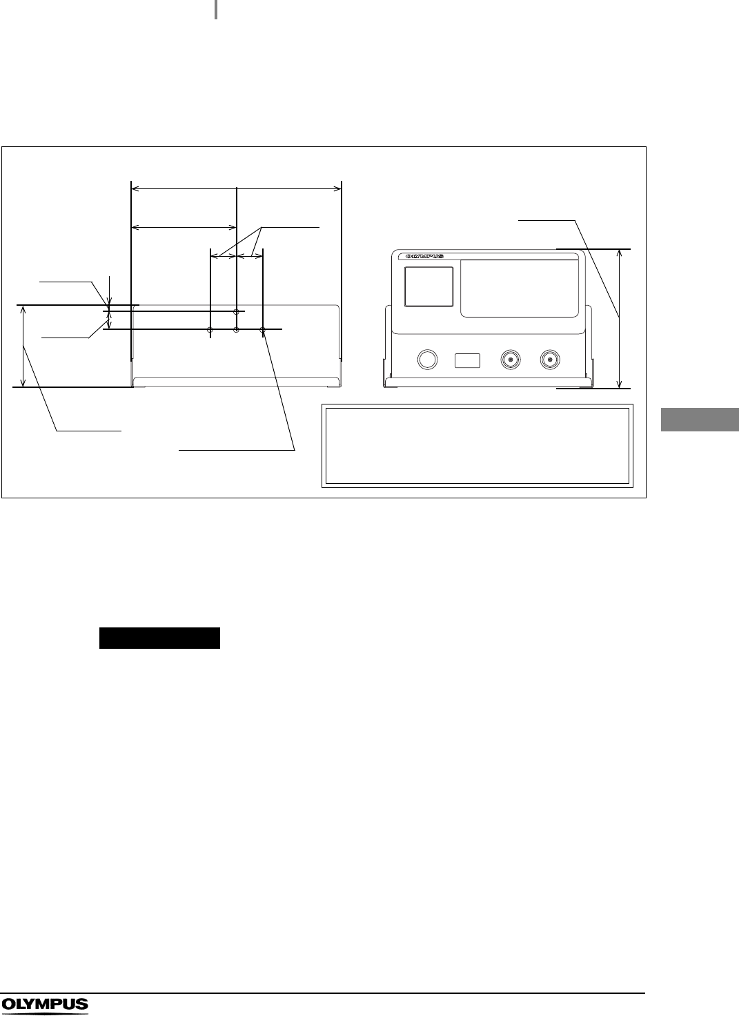
2Referring to the drawings of Figure 3.1 showing the dimensions and weight of the
ALT-Y0003 wall-mount holder, make sure the strength of the wall surface of the four
installation positions. If the strength is insufficient, add reinforcement.
Figure 3.1
3If screws or nuts need screwing into a concrete wall, determine the hole positions
based on the dimension drawing above and embed anchor bolts or nuts equivalent to
“6 mm nominal diameter of bolt”. When embedding the bolts into the wall, protrusion
of the bolt from the wall surface should be 10 mm to 15 mm.
PRECAUTION
Securely hold the ALT-Y0003 wall-mount holder and install it so that it will not fall
off. If the ALT-Y0003 wall-mount holder falls off, it may be damaged.
4Hold the ALT-Y0003 wall-mount holder in the direction as shown in Figure 3.1, align
the holder with the mounting holes, and secure it with screws or nuts. The screw or
nuts to be used for installation should be commercially available and equivalent to
“6 mm nominal diameter of nut or bolt,” which is suited to the material of the wall.
5Make sure that all nuts or bolts are securely tightened. If any of the nuts or bolts
loosen, tighten them again.
304 mm (12.0 in)
152 mm
(6.0 in)
38 mm
(1.5 in)
26 mm
(1.0 in)
10 mm
(0.4 in)
119 mm
(4.7 in)
204 mm
(8.0 in)
Weight of the ALT-Y0003:
Approx.6.5 kg (When accessories are connected)
Weight of the ALT-Y0003 wall-mount holder:
Approx.1.3 kg
Screw/bolt holes
Diameter: ø 8.0
(4 positions)
24
3.3 Installation of the tube hanger
ALT-Y0003 INSTRUCTION MANUAL
Ch.3
Installing the tube hanger on this equipment enables you to hook the endoscope side connector of the
ALT-Y0003 leak test air tube when they are not in use.
PRECAUTION
Avoid placing anything other than the endoscope side connector of the ALT-Y0003
leak test air tubes on the tube hanger. Otherwise the tube hunger may get
damaged.
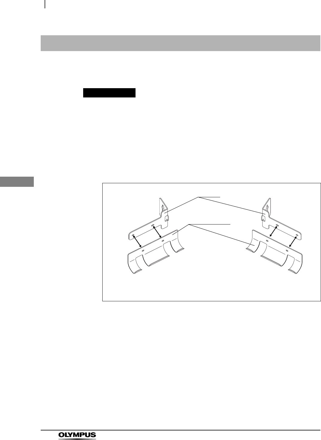
3.3 Installation of the tube hanger
1To install the tube hanger on the right side viewed from the front, align the holes of the
stay and the hanger part as shown in Figure 3.2 (A).
(To install the tube hanger on the left side viewed from the front, align the holes of the
stay and the hanger part as shown in Figure 3.2 (B).)
Figure 3.2
Stay
Hanger parts
(A) When the tube hanger is
installed on the right side viewed
from the front
(B) When the tube hanger is
installed on the left side viewed
from the front
3.3 Installation of the tube hanger
25
ALT-Y0003 INSTRUCTION MANUAL
Ch.3
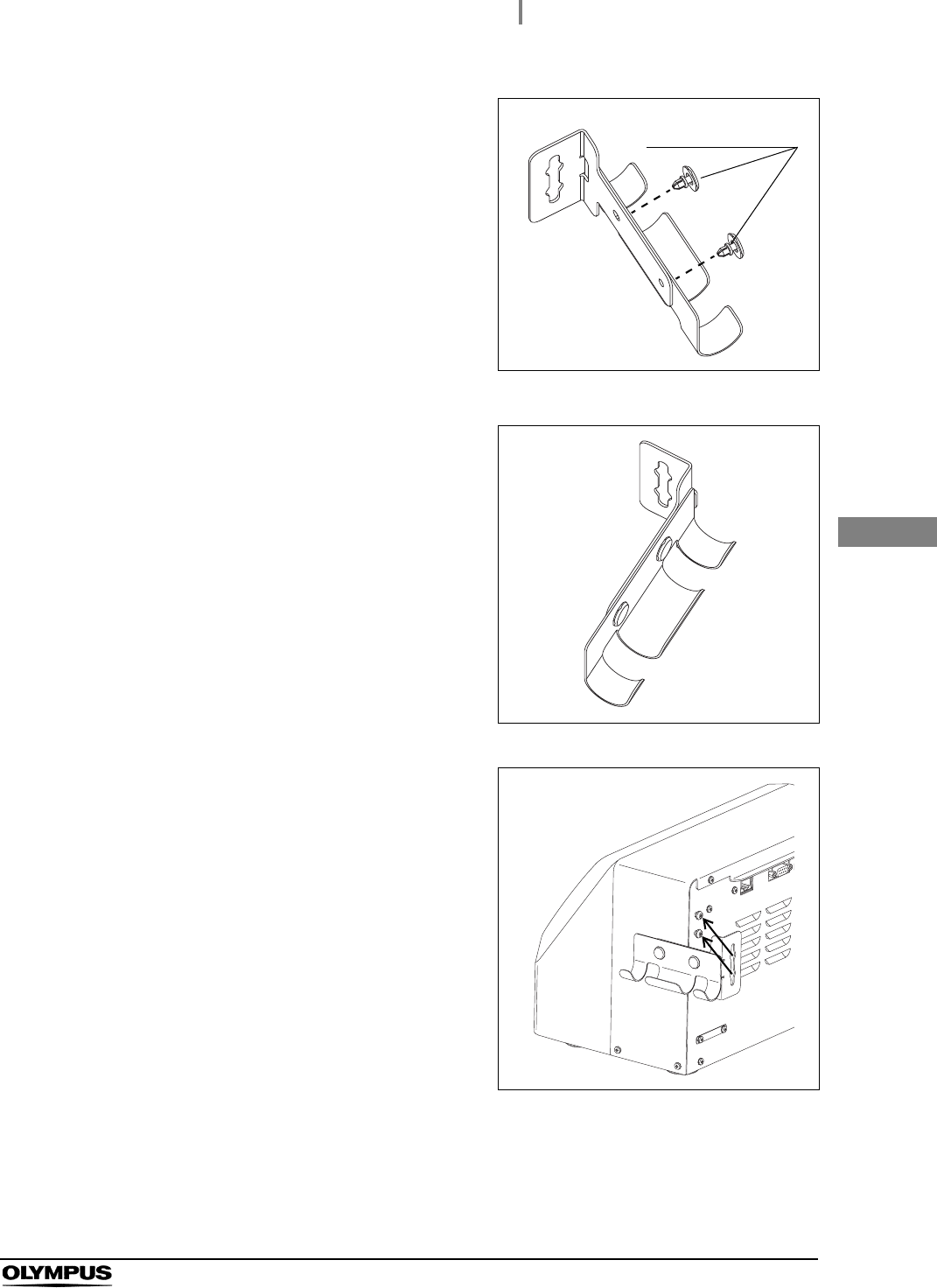
2Align the holes of the stay and the hanger part
and insert the one-touch rivets into the holes
from the hanger part side (see Figure 3.3).
Insert the new one-touch rivets until they hit the
surface of hanger part, and secure the stay to
the hanger part. (See Figure 3.4)
Figure 3.3
Figure 3.4
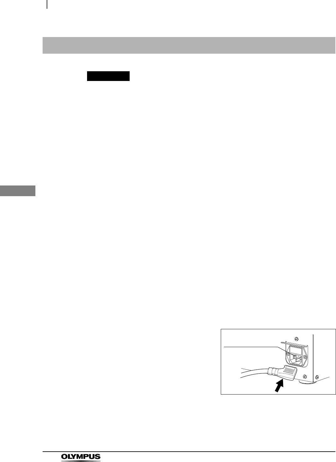
3Align the pins on the rear panel of this
equipment with the grooves of the stay. Push
the stay onto this equipment and slide the stay
downward into position. (To install the tube
hanger in the left side viewed from the front,
match the groove of the stay with the pins on
the right.)
Figure 3.5
One-touch rivets
26
3.4 Connecting the Power Supply
ALT-Y0003 INSTRUCTION MANUAL
Ch.3
WARNING
• Be sure to connect the power plug of the power cord directly to a grounded,
hospital grade, wall mains outlet. If this equipment is not grounded properly, it can
cause an electric shock and/or fire.
• Do not connect the power plug to the 2-pole power circuit with a 3-pole to 2-pole
adapter. It can prevent proper grounding and cause an electric shock.
• Do not allow the power plug to get wet. A wet power plug may cause electric shock.
• Confirm that the grounded wall mains outlet offer adequate electric capacity. In
sufficient capacity may result in a fire or activation of the circuit breaker of the
facility, which turn off the power to all this equipment connected to the same line.
• Do not bend, pull or twist the power cord. Visually inspect the entire length of the
power cord for cracks or cuts. Equipment damage including separation of the
power plug and disconnection of the cord wire as well as fire or electric shock can
result.
• Be sure to connect the power plug securely to prevent its accidental disconnection
during operation. Otherwise, this equipment may not function.
• Do not push the rear of this equipment against the wall after connecting the power
cord. The power supply cord may break, resulting in a fire or electric shock.
• Always use the power cord provided with this equipment. Otherwise, equipment
failure or power cord burnout may result. Also, remember that the provided power
cord is for use only with this equipment and should not be used with any other
equipments.
3.4 Connecting the Power Supply
1Make sure that this equipment is turned OFF.
2Insert the power cord all the way into the
connector on the rear panel (bottom right).
Figure 3.6
3Connect the power cord plug into a hospital-grade, wall mains outlet that meets the
input power conditions indicated on the rating plate.
AC power inlet in
the rear panel
3.5 Connecting the printer
27
ALT-Y0003 INSTRUCTION MANUAL
Ch.3
Connecting a printer (Optional) to this equipment enables you to print the results of leakage testing of
the endoscope.
WARNING
• Use the ALT-Y0003 interface cable (optional) for this equipment. Using a different
interface cable may result in malfunction of this equipment or damage to the
interface cable.
• Do not wet the ALT-Y0003 interface cable. A wet ALT-Y0003 interface cable may
cause an electric shock.
• Do not bend, pull, or twist the ALT-Y0003 interface cable. This may cause fall-off of
the connector or disconnection of the ALT-Y0003 interface cable; a fire or electric
shock may result.
• Be sure to connect the ALT-Y0003 interface cable to prevent its accidental
disconnection during operation. Otherwise, this equipment may not function.
• Make sure that each connector or terminal is free from water on it before
connecting the ALT-Y0003 interface cable. Any water may damage this equipment
or printer.
• Do not push the rear of this equipment against the wall after connecting the
interface cable. The interface cable may bend, resulting in a fire or electric shock.
PRECAUTION
• Read through the instruction manual of the printer before using it.
• Install the printer in an area where it will not get sprayed.
3.5 Connecting the printer
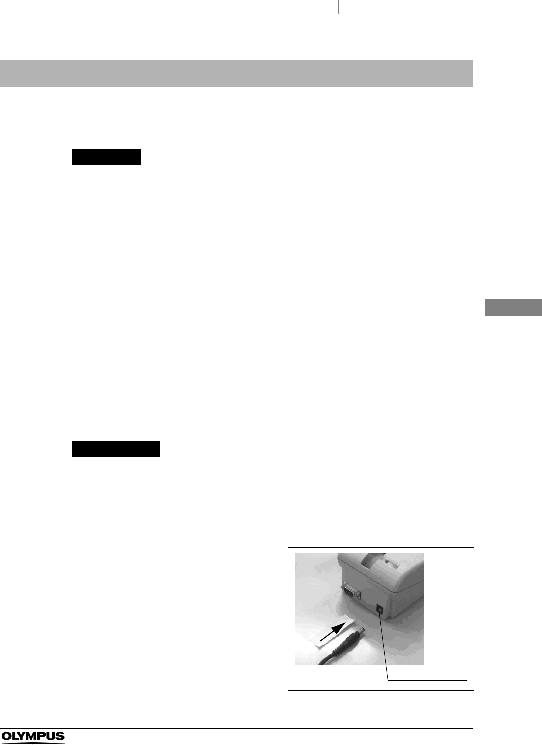
1Make sure that this equipment and printer are turned OFF.
2Make sure that the power cord of the printer is
connected to the printer.
Figure 3.7
AC power inlet
28
3.5 Connecting the printer
ALT-Y0003 INSTRUCTION MANUAL
Ch.3
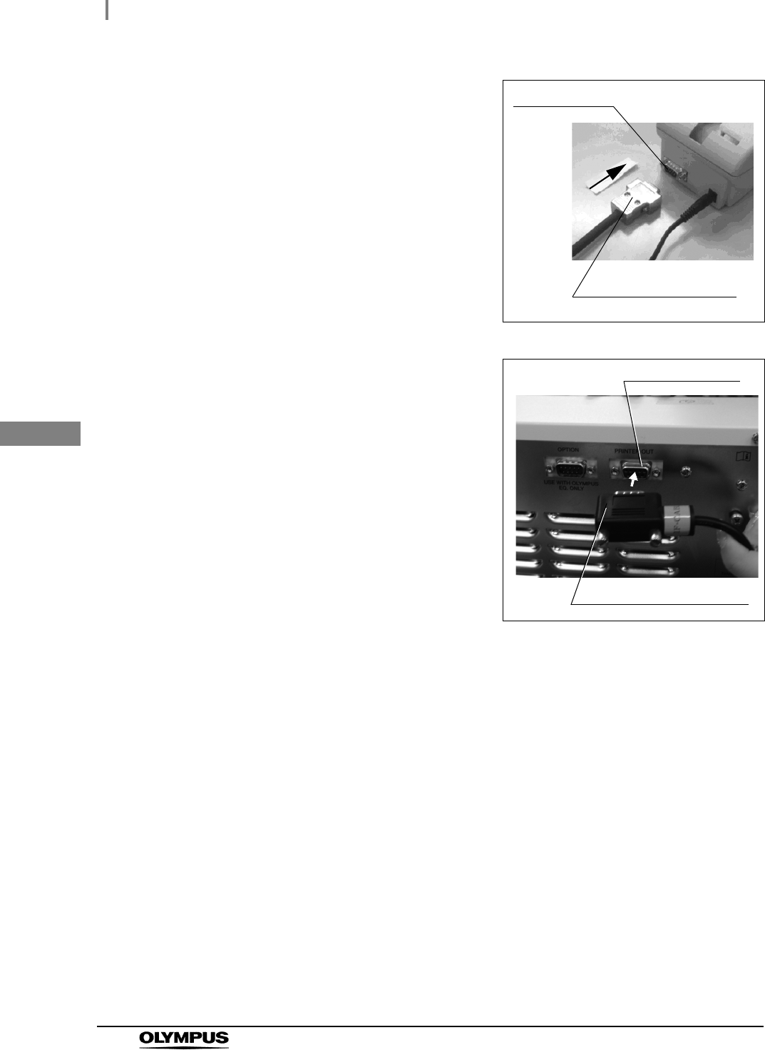
3Connect the ALT-Y0003 interface cable to the
IF connector of the printer.
Figure 3.8
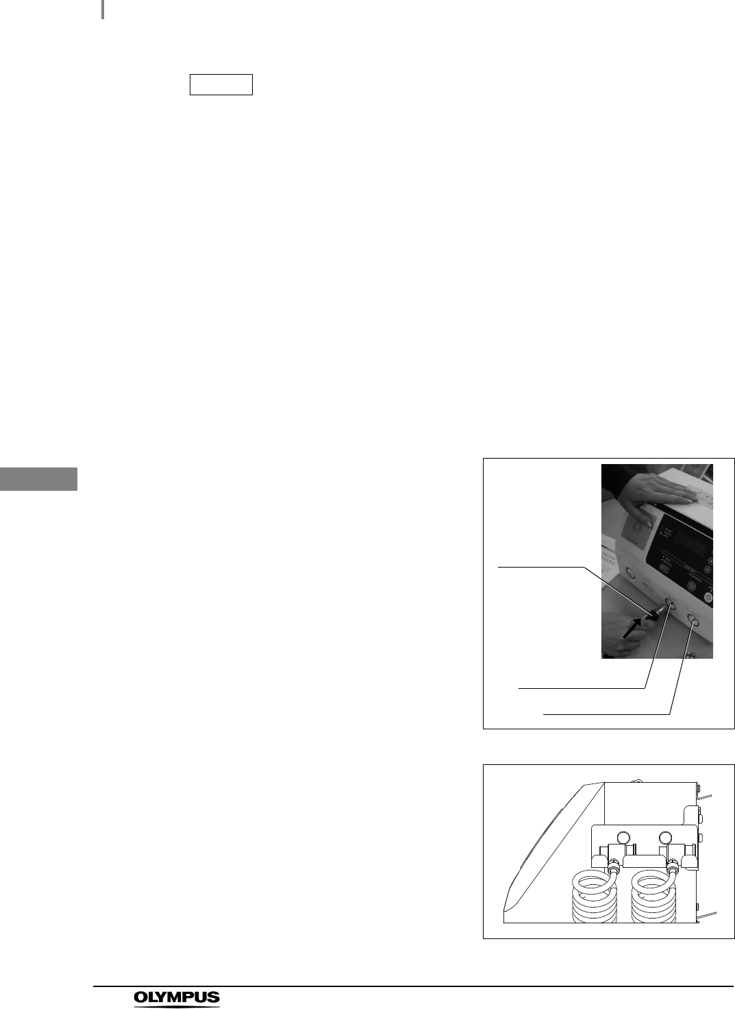
4Connect the ALT-Y0003 interface cable to the
printer terminal of this equipment, and rotate
the screws to fix the cable.
Figure 3.9
IF connector
Printer side connector
Printer terminal
Equipment side connector

4.1 Installing the ALT-Y0003 leak test air tubes and turning ON the power
29
ALT-Y0003 INSTRUCTION MANUAL
Ch.4
Chapter 4 Inspection Before Use
WARNING
Before each use, inspect this equipment as instructed below. Otherwise, this
equipment may not work properly.
Should the slightest irregularity be observed, do not use this equipment and contact
Olympus.
Damage or irregularity may compromise patient or user safety and may result in
more-severe equipment damage.
PRECAUTION
• Check that the outer surface of the ALT-Y0003 leak test air tubes is free from
scratches and flaws. Any scratch or flaw may prevent proper leakage testing.
• When connecting this equipment side connector of the ALT-Y0003 leak test air
tube to the tube connector, make sure that the inside of this equipment side
connector and the outside of the tube connector are not wet. If they are wet,
thoroughly wipe them with a clean cloth. Otherwise, a fluid may enter the
endoscope and the endoscope may fail.
• When connecting this equipment side connector of the ALT-Y0003 leak test air
tube to the tube connector, thoroughly wipe dust, dirt and stain out of the external
surface of the tube connector with a clean cloth. Otherwise, the proper leakage
testing cannot be performed.
• Be sure the ALT-Y0003 leak test air tubes are not tangled. Otherwise, an
unintentional force may act on the tubes. As a result, the tubes may get damaged
or flattened, preventing proper leakage testing.
• Always keep the air vents clear. Blockage can cause overheating and equipment
damage.
• Securely insert the both ALT-Y0003 leak test air tubes into the tube connectors.
Otherwise, a self-check error may occur after power activation. Also, the inside of
endoscope may not be pressurized properly in leakage testing, resulting in a failure
of leakage testing.
• Do not turn ON this equipment within 5 seconds after switching it OFF. This
equipment may not perform properly or fail.
4.1 Installing the ALT-Y0003 leak test air tubes and
turning ON the power
30
4.1 Installing the ALT-Y0003 leak test air tubes and turning ON the power
ALT-Y0003 INSTRUCTION MANUAL
Ch.4
NOTE
• To inform users of the time to replace the internal pump, “Caution Contact Olympus
for New Pump” will be lit up on the LCD monitor upon power activation. When this
indication is lit up, it is time to replace the pump. Turn OFF the power and contact
Olympus.
• Disconnect the water-resistant cap from the ALT-Y0003 leak test air tube if
connected. Otherwise, a self-check error may occur.
1Check that the outer surface of the ALT-Y0003 leak test air tubes is free from
scratches and flaws.
2When connecting the equipment side connector of the ALT-Y0003 leak test air tube to
the tube connector, thoroughly wipe dust, dirt and stain out of the external surface of
the tube connector with a clean cloth.
3Visually check that the inside of the removing grip of the ALT-Y0003 leak test air tubes
and the outside of the tube connector are free from water. If any water is observed,
wipe it with clean cloth.
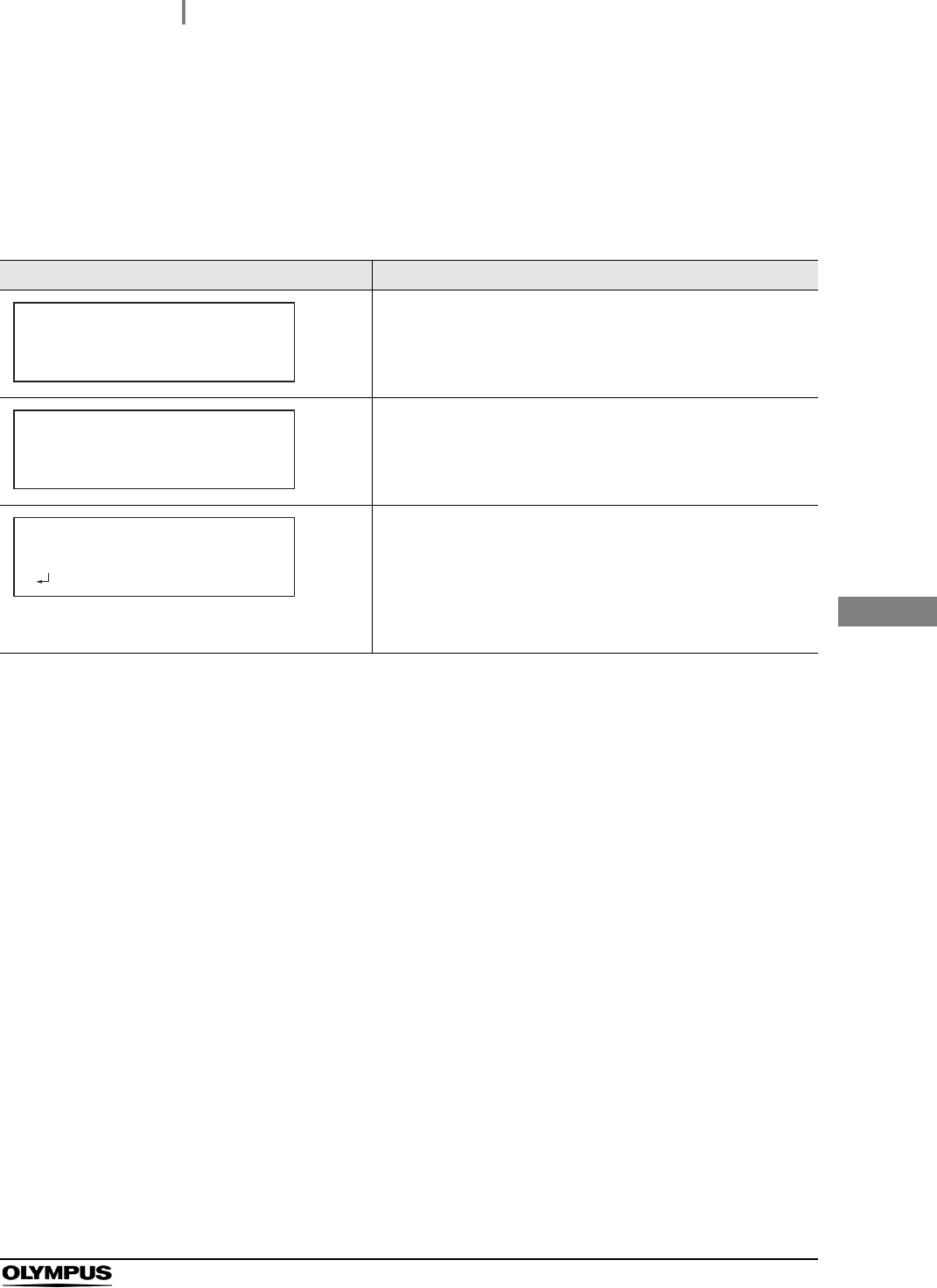
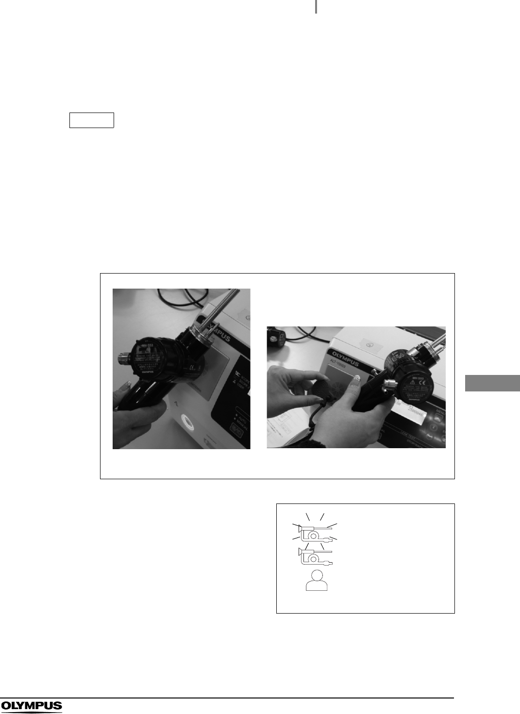
4Using one hand to hold the equipment in place,
hold the connecting grips of the ALT-Y0003
leak test air tube with the other hand and insert
them into the Tube connector 1 and Tube
connector 2 of this equipment until they stop.
Check that they do not come out by pulling
them slightly.
Figure 4.1
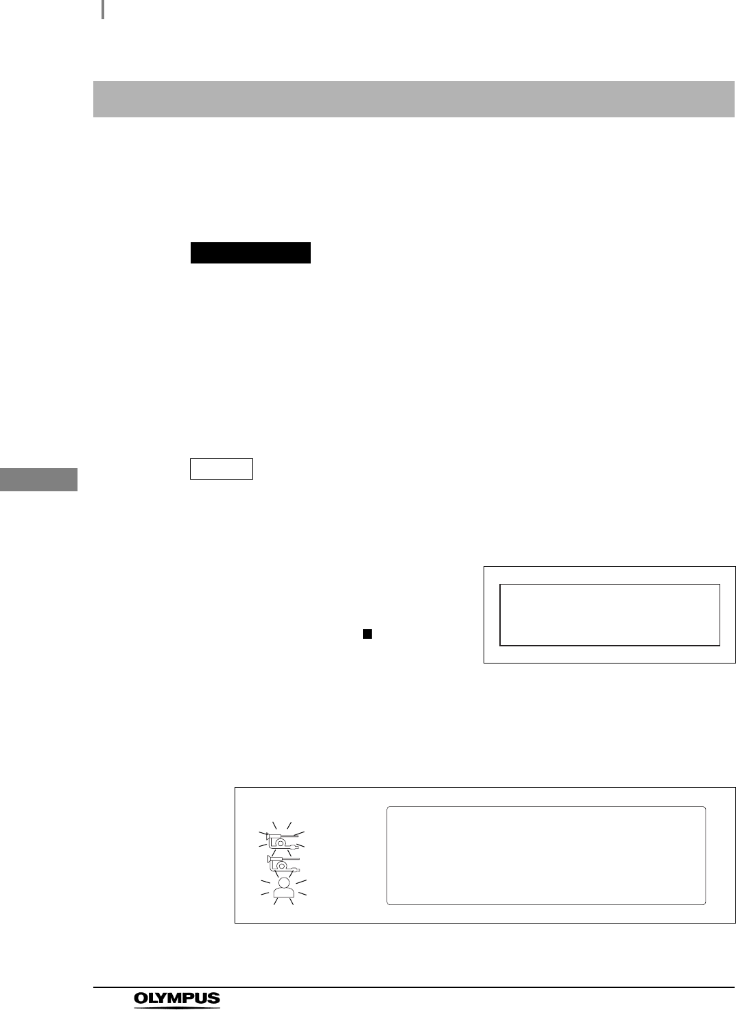
5Set each ALT-Y0003 leak test air tube in the
tube hanger.
Figure 4.2
Tube connector 2
Tube connector 1
Connecting
grips
4.1 Installing the ALT-Y0003 leak test air tubes and turning ON the power
31
ALT-Y0003 INSTRUCTION MANUAL
Ch.4
Tabl e 4 .1
6When using the printer, turn ON the power switch of the printer.
7Turn ON the power switch of this equipment.
8The power indicator will turn ON. The startup screen and the connection status of the
printer will be displayed on the LCD monitor. (See Table 4.1)
Indicator Description
Displayed when Auto Print is not set.
Displayed when Auto Print is set and the power of printer is
turned ON.
Displayed when Auto Print is set and the power of printer is not
turned ON
• When a printer is used, a self-check (Section 4.2)
automatically starts by.turning ON the printer.
• When a printer is not used, a self-check (Section 4.2)
automatically starts by.pressing the OK button.
1.;/275#.6;
#WVQ2TKPV&KUCDNGF
1.;/275#.6;
#WVQ2TKPV#EVKXCVGF
2TKPVGT10
1.;/275#.6;
#WVQ2TKPV#EVKXCVGF
6WTPVJG2TKPVGT10
=?$GIKP5GNH%JGEM
32
4.2 Self-check
ALT-Y0003 INSTRUCTION MANUAL
Ch.4
The self-check is performed to inspect for leakage within the channel and examine whether the pump
or valves works properly. This self-check is automatically performed when the power is turned ON, but
it can be also manually performed when necessary. For the manual self-check, refer to Section 7.3,
“Performing only self-check”.
PRECAUTION
• Do not apply excessive force on the ALT-Y0003 leak test air tubes by forcibly
bending them or placing anything on it. Doing so may prevent a proper self-check
and damage the Leak Test Tubes.
• Do not touch the ALT-Y0003 leak test air tubes during self-check. Otherwise, the
self-check cannot be conducted properly.
• If an error code is displayed on the LCD monitor as a result of the self-check, follow
the instruction in Section 8.1, “Troubleshooting guide”.
NOTE
When self-check is complete, the results of self-check are automatically recorded in
this equipment.
4.2 Self-check
1Turn ON this equipment. A self-check will
automatically start. The “Self Check In
Process” indicator will be displayed on the LCD
monitor. The number of mark “ ” of the
progress bar will increase to show the progress
of the self-check until all the process is
completed.
Figure 4.3
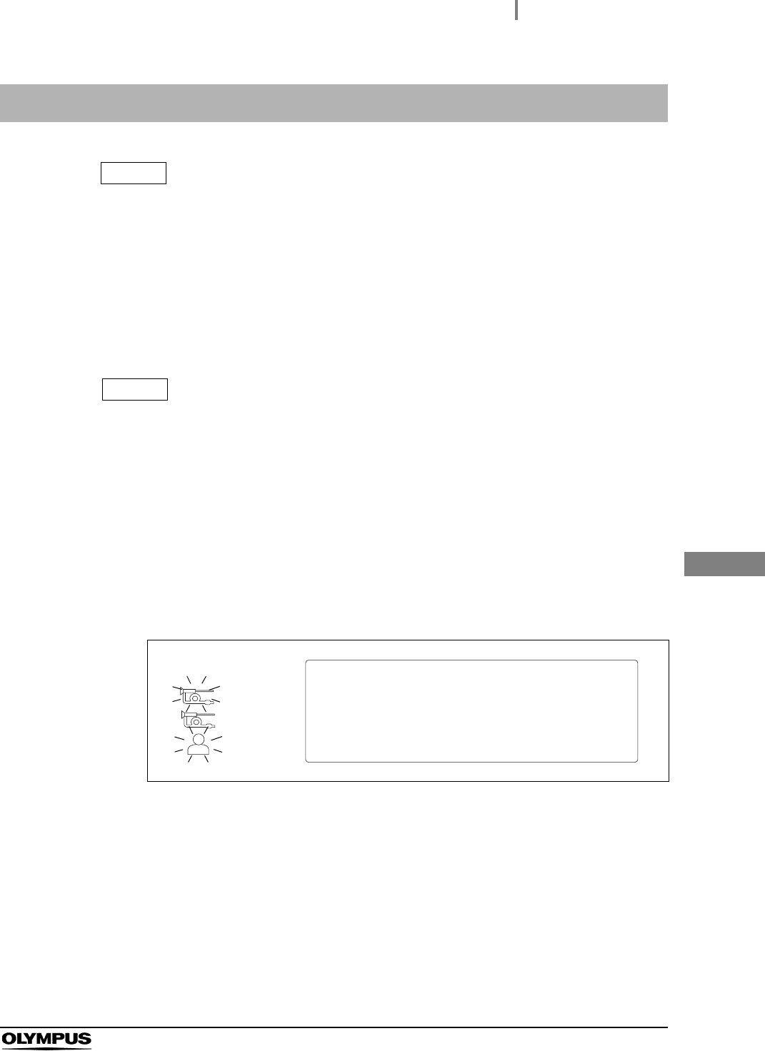
2A short beep sounds when the self-check is completed properly. The “Scope ID
indicator (SCOPE1)” and “User ID indicator (USER)” indicators blinks as shown in
Figure 4.4, and the standby screen appears on the LCD monitor.
Figure 4.4
5GNH%JGEM
KP2TQEGUU
=
عععععޓޓޓޓޓޓޓޓޓޓޓޓ
?
5ECP5EQRG+&
ޓޓޓޓ1T7UGT+&
=/'07?)QVQ/GPW
SCOPE
1
SCOPE
2
USER

4.2 Self-check
33
ALT-Y0003 INSTRUCTION MANUAL
Ch.4
If the error code [E112] is displayed during self-check
If the error code [E112] is displayed in the self-check, make sure the connection between this
equipment and this equipment side connector of the ALT-Y0003 leak test air tube is proper. Press the
Enter button to display the Standby screen and restart a self-check referring to Section 7.3. If the error
code [E112] is still displayed, an irregularity may have occurred in this equipment. Turn OFF the power
switch and contact Olympus.
3When using this equipment for the first time, set the date and time according to
Section 7.1, “Setting date” and Section 7.2, “Setting time”.
4Turn OFF this equipment.
34
4.3 Checking the printer paper roll
ALT-Y0003 INSTRUCTION MANUAL
Ch.4
PRECAUTION
Do not start printing if the printer paper roll is incorrectly installed. Otherwise, the
printer paper roll may jam and/or printing may fail.
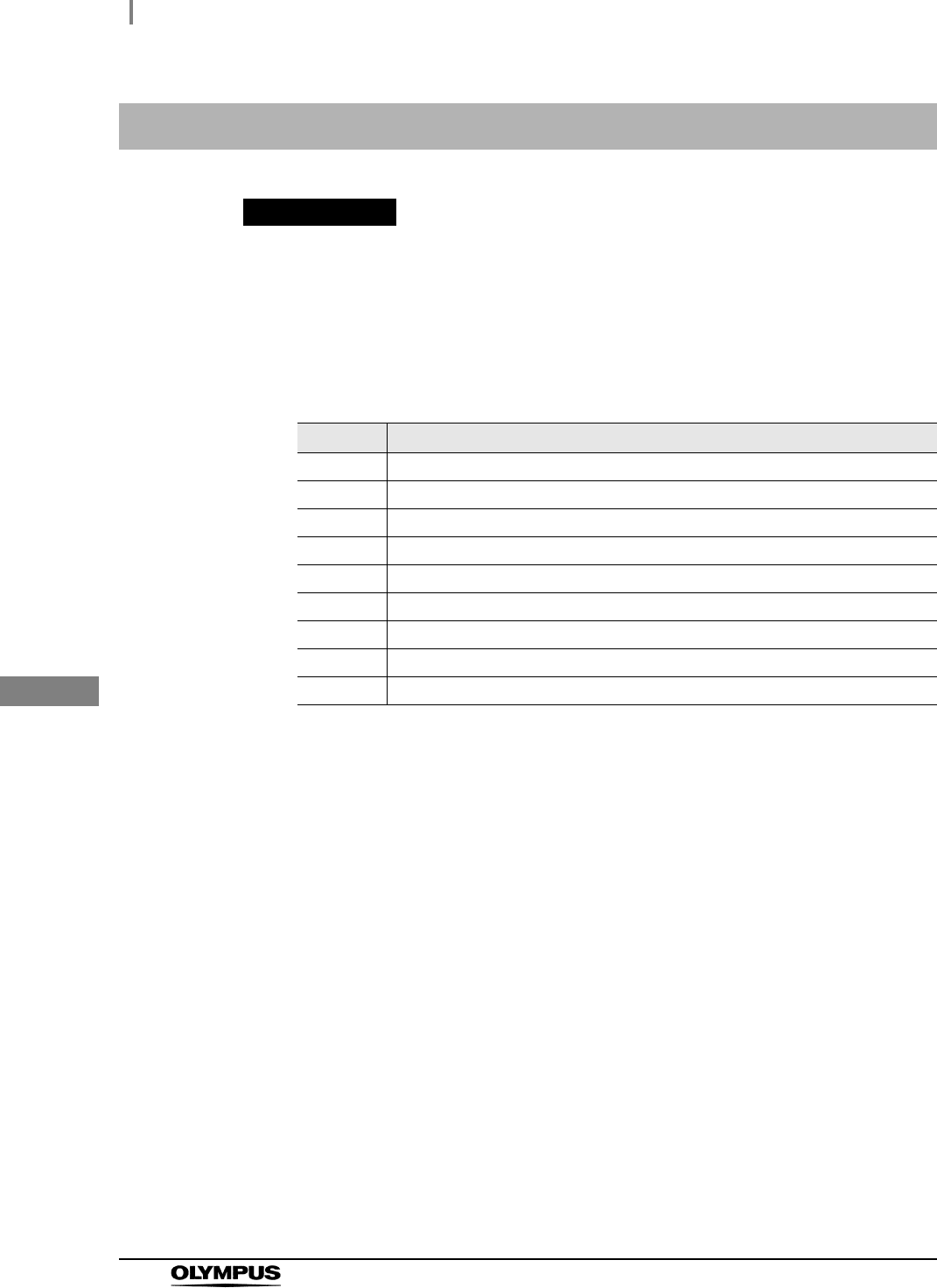
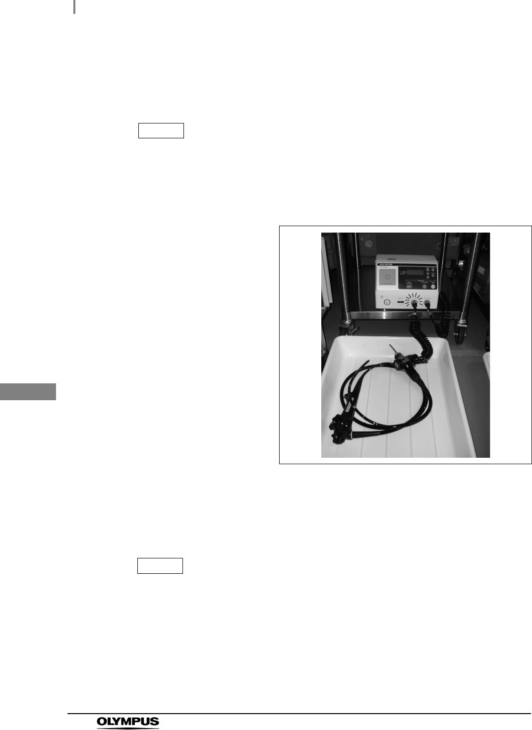
4.3 Checking the printer paper roll
Make sure that the printer paper roll has been installed in this equipment. If not,
replace the printer paper roll according to Section 6.4, “Installing the printer paper
roll”.
Figure 4.5
Transparent window to
check the printer paper
roll

5.1 Precautions for operation
35
ALT-Y0003 INSTRUCTION MANUAL
Ch.5
Chapter 5 Operation
This chapter explains how to perform a leakage test of the endoscope with this equipment.
WARNING
• Be sure to wear protective equipment such as protective eye wear, face mask,
moisture-resistant gloves that fit properly and are long enough so that your skin is
not exposed. Otherwise, dangerous chemicals and/or potentially infectious material
such as blood and/or mucus of the patient may cause an infection.
• Wear gloves long enough to protect your skin and exchange them regularly so that
they do not get torn.
• Should any irregularity be observed, do not use this equipment. Damage or
irregularity may cause an electric shock, burns and/or fire.
• Do not allow the Power cord to become wet. A wet Power cord may cause an
electric shock.
• After leakage testing with this equipment, reprocess the endoscope following all
applicable national and local guideline. Endoscopy or endoscopic therapy with an
endoscope not reprocessed may result in infections of a patient or operator.
PRECAUTION
• More than three minutes after withdrawing the endoscope from the body, perform
an automatic leakage test. The endoscope upon removal from the body may be
exposed to a sudden temperature change, resulting in an inaccurate test.
• Select the Standard Mode in the automatic leakage test mode (ALT mode) if more
than seven minutes have passed after removal of the endoscope from the body. If
seven minutes have not passed after removal of the endoscope from the body,
select the Quick Mode. The endoscope upon removal from the body may have a
temperature greatly different from ambient temperature and undergo a sudden
temperature change, resulting in an inaccurate test. (See Section 7.4, “Setting
automated leakage test mode”.)
• Install endoscopes to be automatically leak-tested in a location not exposed to
direct sunlight and air conditioning. A rapid temperature change in the endoscopes
may cause improper automated leak testing.
5.1 Precautions for operation

36
5.1 Precautions for operation
ALT-Y0003 INSTRUCTION MANUAL
Ch.5
NOTE
• To perform a leakage test in this equipment, an endoscope must be of a type with a
built-in Scope ID or have a Scope ID tag. In addition, a USER ID card is required.
• This equipment can be stopped at any time during operation by pressing the
STOP/BACK button. When a process is interrupted, be sure to execute it again
from the beginning.
5.2 Operation workflow
37
ALT-Y0003 INSTRUCTION MANUAL
Ch.5
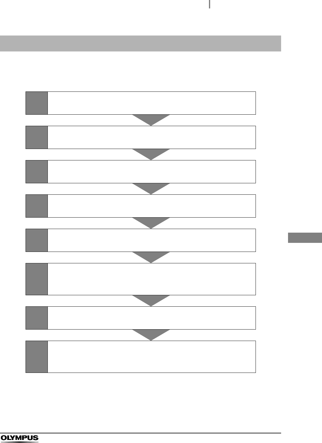
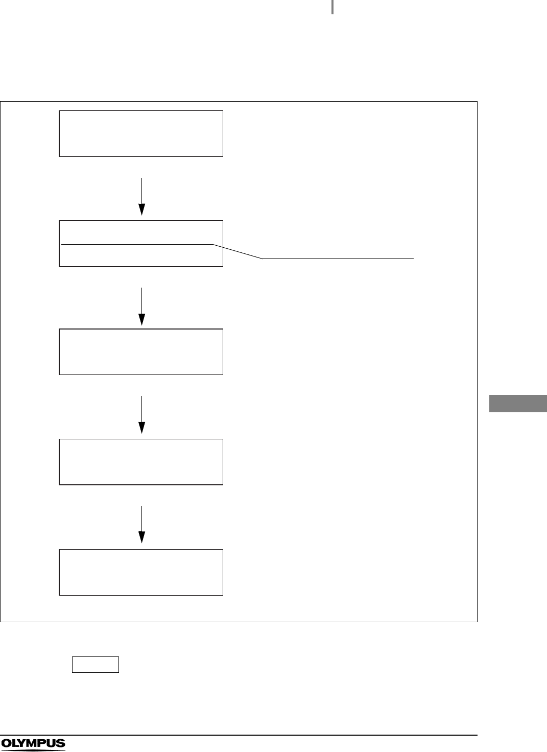
The chart below shows the leakage test work flow. Review and understand each step before use to
obtain an accurate leakage test result.
5.2 Operation workflow
1Prepare equipment before use
Section 5.3 on page 38
2Turn the power ON
Section 5.4 on page 39
3Have the scope ID recognized
Section 5.5 on page 40
4Connect the ALT-Y0003 leak test air tube with the endoscope
Section 5.6 on page 44
5Have the user ID recognized
Section 5.7 on page 46
6
Perform leakage testing
• Automated leakage testingSection 5.8 on page 47
• Manual leakage testingSection 5.9 on page 52
7Care for the ALT-Y0003 leak test air tubes
Section 6.2 on page 58
8
Proceed to the next step
• To continue leakage testingSection 5.5 on page 40
• To finish leakage testingSection 6.3 on page 61
38
5.3 Preparation before use
ALT-Y0003 INSTRUCTION MANUAL
Ch.5
PRECAUTION
Use a basin deep enough to allow complete immersion of the endoscope and large
enough for the insertion section of the endoscope and the universal cord to be
coiled into a diameter of 17 cm or over. If the insertion section or universal cord is
coiled into a smaller diameter, the leakage testing may not be conducted properly.
Prepare equipment as shown below.
5.3 Preparation before use
Check Required items
This Automated Endoscope Leak Tester
ALT-Y0003 leak test air tubes (MAJ-2009) (× 2)
Personal protective equipment
A clean and large basin (Prepare two basins if two endoscopes are tested.)
Endoscope with a built-in Scope ID memory chip or a Scope ID tag
Water-resistant cap (only for EVIS series endoscope)
ID chip (MAJ-1546) (optional)
Printer (MAJ-1937) (optional)
ALT-Y0003 interface cable (MAJ-2052) (optional)
5.4 Power activation
39
ALT-Y0003 INSTRUCTION MANUAL
Ch.5
NOTE
• When the printer is used, turn ON the printer before turning ON this equipment.
• For indicators on the printer after power activation, refer to Table 4.1 in Section 4.1,
“Installing the ALT-Y0003 leak test air tubes and turning ON the power”.
5.4 Power activation
1Confirm that ALT-Y0003 leak test air tubes are surely connected to Tube connector 1
and 2 of this equipment. Also confirm that an endoscope or no water resistance caps
are connected to the endoscope connectors of ALT-Y0003 leak test air tubes.
NOTE
An error code [E112] is displayed on turning power ON if the ALT-Y0003 leak test
air tubes are not securely connected to this equipment, or if an endoscope or water
resistance cap is connected to the ALT-Y0003 leak test air tubes.
2Turn the power switch ON.
3A self-check start automatically.
4A short beep sounds when the self-check is completed properly. As seen in Figure
5.1, the Scope ID indicator (SCOPE1) and User ID indicator (USER) indicators blink.
The Standby screen is displayed on the LCD monitor.
Figure 5.1
5ECP5EQRG+&
ޓޓޓޓ1T7UGT+&
=/'07?)QVQ/GPW
SCOPE
1
SCOPE
2
USER
40
5.5 Recognition of scope ID
ALT-Y0003 INSTRUCTION MANUAL
Ch.5
To keep an endoscopic leak test log, have this equipment recognize the individual scope ID that
identifies the endoscope to be tested.
PRECAUTION
• Have this equipment recognize the scope ID of the endoscopes to be leak-tested.
Otherwise, the leakage testing can not be recorded properly.
• Do not bang the scope ID tag or scope connector onto the RFID reader during
scope ID recognition. This may damage the scope ID tag, scope connector, and
RFID reader.
NOTE
• The START button on the main control panel does not function unless the User ID
has been recognized.
• Two endoscopes may not be tested simultaneously depending on the compatibility
of the endoscopes. Refer to the “List of Compatible Endoscopes <ALT-Y0003>” for
the endoscope that cannot be tested simulataneously. If you attempt to have this
equipment recognize the second ID, the panel will display the message as shown
in Figure 5.2, and the endoscope ID can not be detected. Press the ENTER button
to restart the scope ID detection procedure.
Figure 5.2
• For manual leakage testing, you can have the RFID reader detect the provided
scope ID master card. (Automated leakage testing cannot be performed.) However,
two endoscopes can not be tested simultaneously in a manual leakage test. Test
the endoscope individually.
• If the scop ID master card is used, the history logs of the endoscope can not be
managed.
• If any irregularity is found with the scope ID recognition of this equipment, or if any
irregularity is suspected of the scope ID, contact Olympus.
• For addition or reissue of a scope ID, contact Olympus.
5.5 Recognition of scope ID
%CWVKQP
)+(:::
&QGUPQVCRRN[
=?'PVGT
5.5 Recognition of scope ID
41
ALT-Y0003 INSTRUCTION MANUAL
Ch.5
1Confirm that ALT-Y0003 leak test air tubes are surely connected to Tube connector 1
and 2 of this equipment. Also confirm that an endoscope or no water resistance caps
are connected to the endoscope connectors of ALT-Y0003 leak test air tubes.
NOTE
The error code [E123] is displayed on the monitor when you try to read the scope
with the following conditions:
The ALT-Y0003 leak test air tubes is disconnected, or
An endoscope or water-resistant cap is connected to the ALT-Y0003 leak test
air tubes
2Bring the ID tag attached to the endoscope closer to the RFID reader of this
equipment, and scan the tag with the reader until a short beep sounds.
Figure 5.3
3Make sure that the Endoscope ID indicator
“SCOPE 1” lights up on the control panel.
Figure 5.4
For internal ID-type endoscope For external ID tag
SCOPE
1
SCOPE 2
USER
42
5.5 Recognition of scope ID
ALT-Y0003 INSTRUCTION MANUAL
Ch.5
NOTE
• When the first endoscope is detected, the Endoscope ID indicator “SCOPE 1” lights
up.
• When the second endoscope is detected, the Endoscope ID indicator “SCOPE 2”
lights up.
• To replace the endoscope to be tested, press the STOP/BACK button and
disconnect the endoscope from the ALT-Y0003 leak test air tube. Go back to the
beginning of Section 5.5 and repeat the steps.
4Check that the Tube connector 1 indicator is blinking. Connect an endoscope to the
ALT-Y0003 leak test air tube connected to Tube connector 1 according to the
instruction described in Section 5.6, “Connecting ALT-Y0003 leak test air tubes and
endoscope”.
NOTE
The error code [E122] is displayed when, in the step 4 above, an endoscope is
connected to the ALT-Y0003 leak test air tube that has been connected to Tube
connector 2. Press the Enter button and detach the endoscope from the
ALT-Y0003 leak test air tube. Go back to beginning of Section 5.5 and repeat the
steps.
Figure 5.5
5To leak test a second scope, repeat steps 1 – 4 above, and connect the second
endoscope to the ALT-Y0003 leak test air tube connected to “Tube connector 2".
5.5 Recognition of scope ID
43
ALT-Y0003 INSTRUCTION MANUAL
Ch.5
The LCD monitor indicators change as shown in Figure 5.6 below when the ID is entered or when the
endoscope is connected.
Figure 5.6
NOTE
When the STOP/BACK button is pressed in any screen from (b) to (e) in Figure 5.6
above, the screen returns to “(a) Standby screen (Waiting for the input of ID)”. In
this case, all the scope IDs and user IDs need recognizing again.
5ECP5EQRG+&
ޓޓޓޓ1T7UGT+&
=/'07?)QVQ/GPW
%QPPGEV5EQRG
)+(:::
5ECP7UGT5EQRG+&
)+(:::
%QPPGEV5EQRG
)+(:::
)+(;;;
5ECP7UGT+&
)+(:::
)+(;;;
(a) Standby screen (Waiting for ID entry)
Recognition of Scope ID (of a first endoscope)
(b) Waiting for the connection of an endoscope
Connect the endoscope to Scope Connector 1
(c) Waiting for ID entry
Recognition of Scope ID (of a second endoscope)
(d) Waiting for the connection of another endoscope
Connect the endoscope to Scope Connector 2
(e) Standby screen (Waiting for ID entry
Endoscope Code No./Serial No.

44
5.6 Connecting ALT-Y0003 leak test air tubes and endoscope
ALT-Y0003 INSTRUCTION MANUAL
Ch.5
Set the endoscope for automated leak testing and connect it to the ALT-Y0003 leak test air tube.
PRECAUTION
• Be sure to confirm that the basin does not contain any water or a disinfectant
solution before filling the basin with water. If there is any pin hole in the endoscope,
the fluid may enter the endoscope, resulting in malfunction of the endoscope.
• For an endoscope that requires a water-resistant cap, be sure to inspect and attach
the cap as described in the “Instruction Manual” of the endoscope. Otherwise, the
inside of endoscope may not be pressurized, resulting in inaccurate leakage
testing. Attaching the water-resistant cap that is wet inside may cause malfunction
of the endoscope.
• When attaching the endoscope connector of the ALT-Y0003 leak test air tube to the
venting connector of the endoscope or water-resistant cap, check if the O ring
inside the endoscope connector is present and free from scratches or flaws.
Otherwise, accurate leakage testing cannot be conducted.
• When attaching the endoscope connector of the ALT-Y0003 leak test air tube to the
venting connector of the endoscope or water-resistant cap, wipe out any water drop
inside the endoscope connector and outside the venting connector. Such a water
drop may enter the endoscope, resulting in malfunction of the endoscope.
• When attaching the endoscope connector of the ALT-Y0003 leak test air tube to the
venting connector of the endoscope or water-resistant cap, wipe out any dust, dirt,
or stain inside the endoscope connector and outside the venting connector.
Otherwise, accurate leakage testing cannot be conducted.
• Be sure to attach the endoscope side connector of ALT-Y0003 leak test air tube to
the venting connector of the endoscope or water-resistant cap. Otherwise, the
inside of endoscope is not pressurized; resulting in inaccurate leakage testing.
• Do not place two endoscopes in the basin with any part of them stacked with each
other. Accurate leakage testing cannot be conducted.
• Place the endoscope in the basin with the bending section of the endoscope
straight and the insertion section and universal cord coiled into a diameter of 17 cm
or over in performing automated leak testing. Otherwise, accurate leakage testing
cannot be conducted.
5.6 Connecting ALT-Y0003 leak test air tubes and
endoscope
5.6 Connecting ALT-Y0003 leak test air tubes and endoscope
45
ALT-Y0003 INSTRUCTION MANUAL
Ch.5
1Confirm that the basin does not contain any water or disinfectant solution.
2Place the endoscope in the basin. (When two endoscopes are tested simultaneously,
place each endoscope into a different basin.)
Make the bending section of the endoscope straight and the insertion section and
universal cord coiled into a diameter of 17 cm or over.
3Visually check that there is no water drop, dust, dirt, nor stain inside the endoscope
connector of the ALT-Y0003 leak test air tube and outside the venting connector of
either endoscope or water-resistant cap.
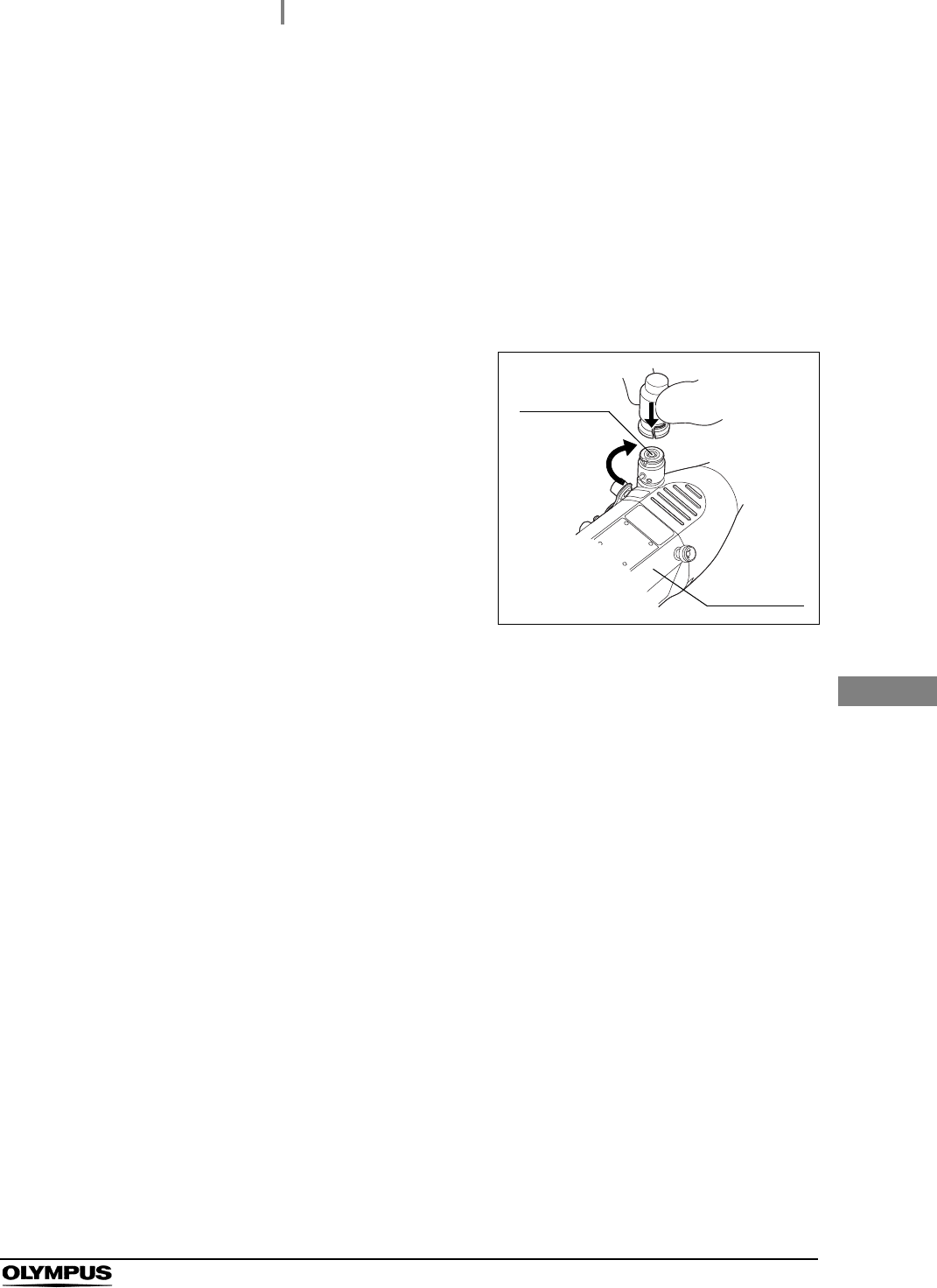
4Turn the endoscope connector of the
ALT-Y0003 leak test air tube clockwise until it
stops, pushing it to the venting connector as
shown in Figure 5.7.
Figure 5.7
5When the ALT-Y0003 leak test air tubes is connected to the scope, the Tube
Connector Indicator stops blinking and starts to light.
Venting
connector
Endoscope
connector
46
5.7 Recognition of user ID
ALT-Y0003 INSTRUCTION MANUAL
Ch.5
To keep an endoscope leak test log, have this equipment recognize the individual User ID that
identifies the reprocessing operator.
NOTE
• The START button on the main control panel does not function unless the User ID
has been recognized.
• For addition or re-issue of the user ID card, contact Olympus.
• If this equipment fails to detect the user ID, apply the provided user ID master card
to the RFID reader so that this equipment recognizes the user ID as the master ID.
If a problem with the user ID is observed, contact Olympus.
NOTE
• When the User ID detection indicator does not illuminate on the control panel, the
user ID card has not been recognized. Bring the user ID card again close to the
RFID reader of equipment.
• To replace the endoscope to be tested, press the STOP/BACK button and
disconnect the endoscope from the ALT-Y0003 leak test air tube. Go back to the
beginning of Section 5.5 and repeat the steps.
5.7 Recognition of user ID
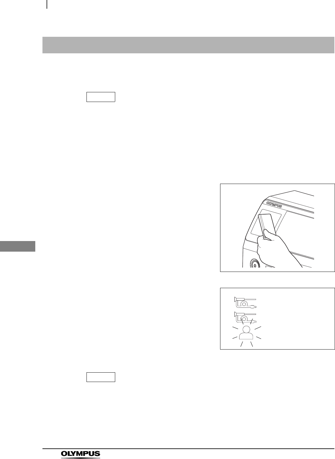
1Bring the user ID card of the leakage testing
worker close to the RFID reader of this
equipment until a short beep sounds.
Figure 5.8
2Confirm that the User ID detection indicator on
the control panel is turned ON.
Figure 5.9
SCOPE
1
SCOPE 2
USER

5.8 Automated leakage testing
47
ALT-Y0003 INSTRUCTION MANUAL
Ch.5
This equipment features the following functions for the automated leakage testing:
• This equipment can perform a leakage test in air in an ALT; you do not need to store water in
the basin.
• This equipment performs automatic leakage testing of the endoscope.
• This equipment can store the records of leakage testing.
WARNING
Be sure to wear protective gear such as moisture-resistant clothes, goggles, a face
mask, chemical-resistant gloves that fit properly and are long enough so that your
skin is not exposed. Otherwise, potentially infectious materials attached to the
endoscope, such as blood and/or mucus of the patient, may cause an infection.
PRECAUTION
Do not immerse the endoscope in water nor touch it during Automated Leakage
Testing. Accurate leakage testing cannot be conducted.
NOTE
• Automated leak testing can not start without recognition of both Scope ID and User
ID. Read the both Scope ID and User ID, referring to Section 5.5, “Recognition of
scope ID” and Section 5.7, “Recognition of user ID”.
• For the setting of history printing, see Section 7.5, “Setting print mode”.
• The air fed into the endoscope may slightly expand the rubber cover of the bending
section. This is not an abnormality.
• When a leakage test ends, the result is automatically recorded in this equipment.
• Up to 13,000 records of leakage testing can be stored in this equipment. If more
than 13,000 records are stored, the oldest record is overwritten.
• To stop the leakage test during operation, press the STOP/BACK button.
• A quite small pin hole may not be detected in automated leakage testing.
• Endoscopes not listed in the “List of Compatible Endoscopes <ALT-Y0003>” can
not be automatically leak-tested. If an incompatible endoscope is connected, only
the MANUAL light lights up when the SELECT button is pressed.
5.8 Automated leakage testing