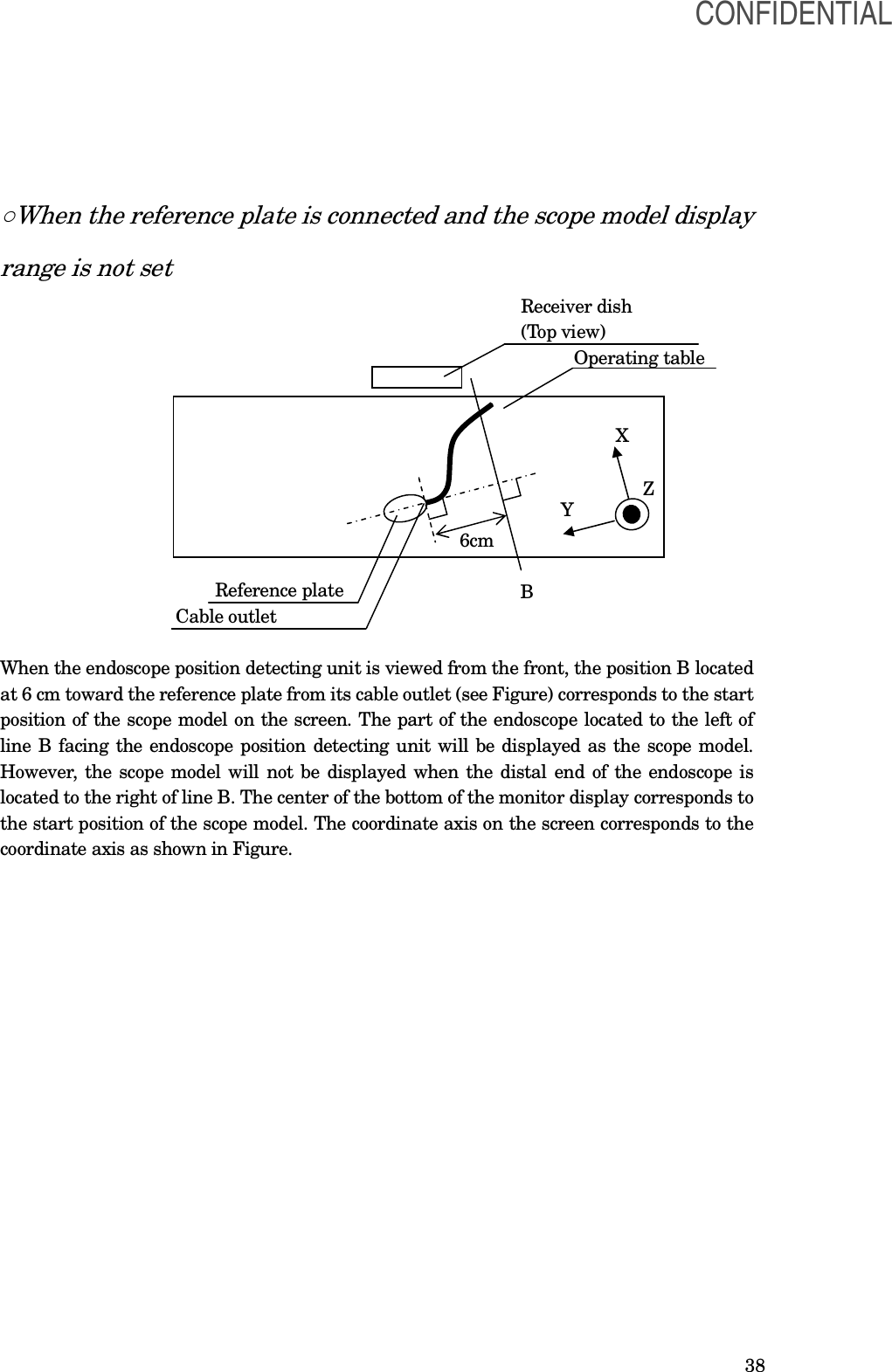
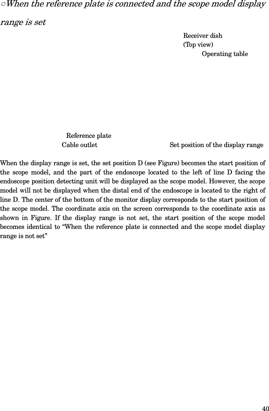
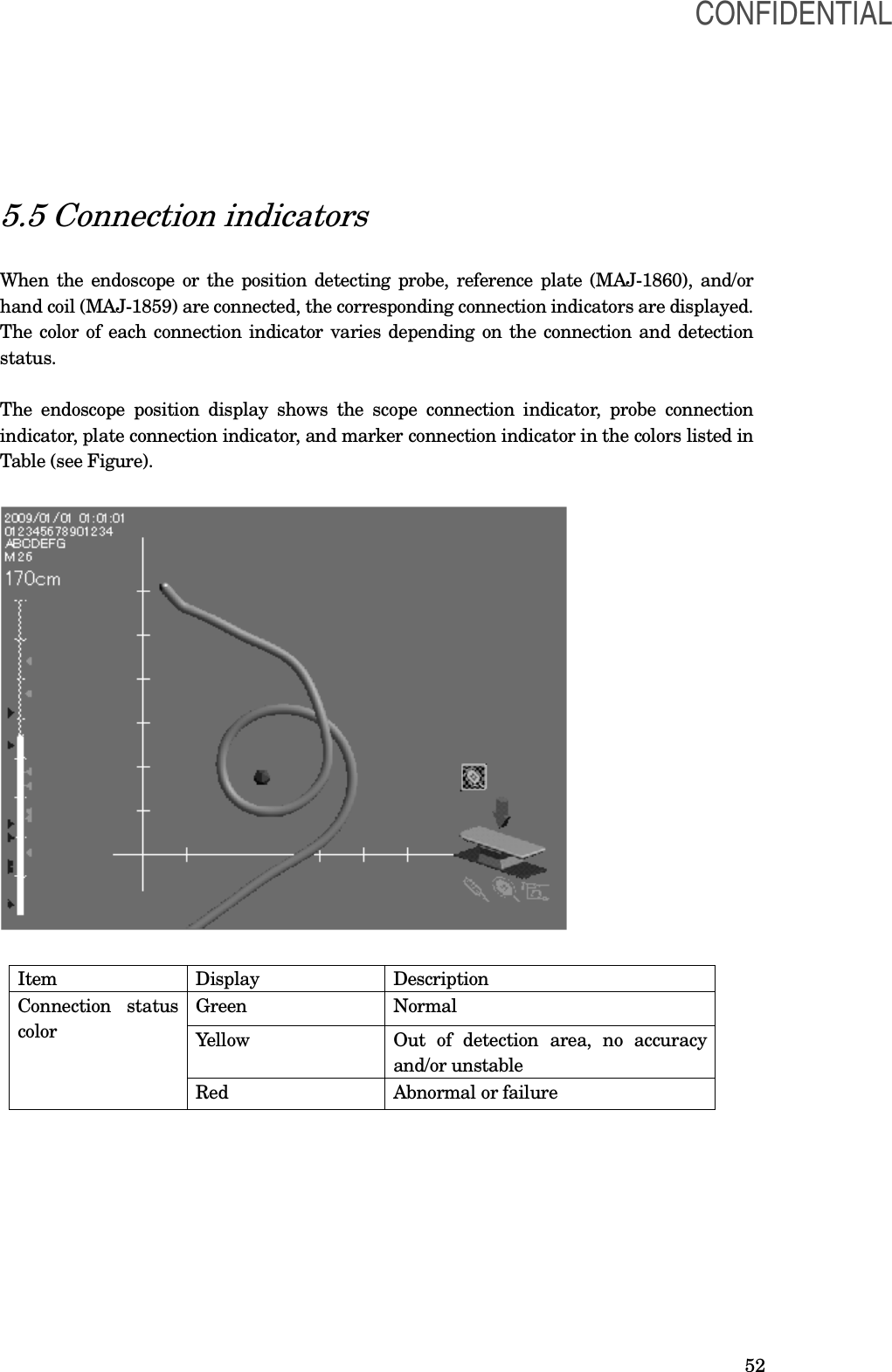
Olympus Medical Systems UPD-3 Endoscope Position Detecting Unit User Manual Instruction Manual
Olympus Medical Systems Corp. Endoscope Position Detecting Unit Instruction Manual
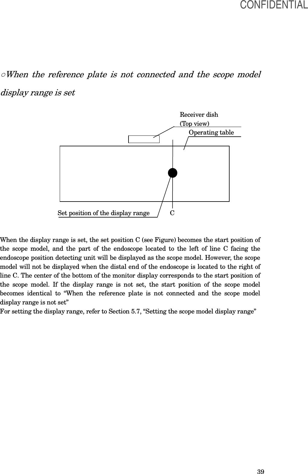
Contents
- 1. Instruction Manual
- 2. Excerpt of the user manual
Instruction Manual
![7 Signal words The following signal words are used throughout this manual: [DANGER] Indicates an imminently hazardous situation which, if not avoided, will result in death or serious injury. [WARNING] Indicates a potentially hazardous situation which, if not avoided, could result in death or serious injury. [CAUTION] Indicates a potentially hazardous situation which, if not avoided, may result in minor or moderate injury. It may also be used to alert against unsafe practices or potential equipment damage. [NOTE] Indicates additional helpful information. Dangers, warnings and cautions Follow the dangers and cautions given below when handling this endoscope position detecting unit. This information is to be supplemented by the dangers and cautions given in each chapter. [DANGER] •As a TYPE BF applied part, the endoscope connected to this instrument must never be applied directly to the heart. Leakage current from the TYPE BF applied part may be dangerous and cause ventricular fibrillation or otherwise seriously affect the cardiac function of the patient. Accordingly, always adhere to the following: − Never apply the endoscope connected to this instrument to the heart or any area near the heart. − Never allow an EndoTherapy accessory or another endoscope applied to or near the heart to come in contact with the endoscope connected to this instrument. •Strictly observe the following precautions. Failure to do so may place the patient and medical personnel in danger of electric shock. − When this endoscope position detecting unit is used to examine a patient, do not allow metal parts of the endoscope or its accessories to touch metal parts of other system components. Such contact may cause unintended current flow to the patient. − Keep fluids away from all electrical equipment. If fluids are spilled on or into the unit, stop operation of the endoscope position detecting unit immediately and contact Olympus. CONFIDENTIAL](https://usermanual.wiki/Olympus-Medical-Systems/UPD-3.Instruction-Manual/User-Guide-1366365-Page-7.png)
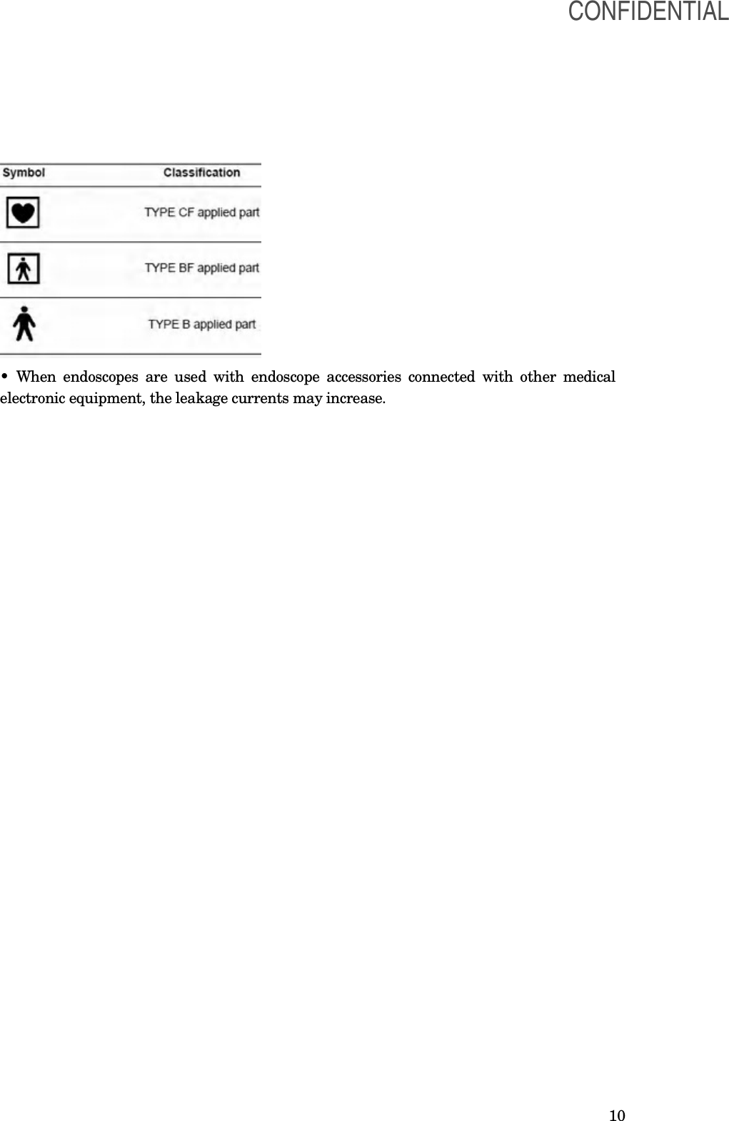
![9 [WARNING] • Never insert anything into the ventilation grills of the endoscope position detecting unit. It can cause an electric shock and/or fire. • This product may interfere with other medical electronic equipment used in combination with it. Before use, refer to the Appendix to confirm the compatibility of this instrument with all equipment to be used. • Do not use this product in any place where it may be subject to strong electromagnetic radiation (for example, in the vicinity of a microwave therapeutic device, MRI, wireless set, short-wave therapeutic device, cellular/portable phone, etc.). This may impair the performance of the product. [CAUTION] • Do not touch the electrical contacts inside the instrument’s connectors. Otherwise, equipment damage and/or malfunction can occur. • Do not use a pointed or hard object to press the buttons on the front panel and/or keyboard. This may damage the buttons. • Do not apply excessive force to the connectors. Otherwise, a failure of an electrical contact may result in a malfunction. • This instrument emits RF (Radio Frequency) energy to supply data by radio communication. Therefore, it may cause electromagnetic interference in nearby electronic equipment, and is labeled with the following symbol. If electromagnetic interference occurs, mitigation measures may be necessary, such as moving the electronic equipment away, reorienting or relocating this instrument, or shielding the location. [NOTE] • As defined by the international safety standard (IEC 60601-1), medical electrical equipment is classified into the following types: TYPE CF applied part (the instrument can safely be applied to any part of the body, including the heart), and TYPE B/BF applied part (the instrument can safely be applied to any organ except the heart). The part of the body that an endoscope or electrosurgical accessory can safely be applied to depends on the classification of the equipment to which the instruments are connected. Before beginning the procedure, check the current leakage classification type of each instrument to be used for the procedure. Classification types are clearly specified in the instruments' instruction manuals. CONFIDENTIAL](https://usermanual.wiki/Olympus-Medical-Systems/UPD-3.Instruction-Manual/User-Guide-1366365-Page-9.png)
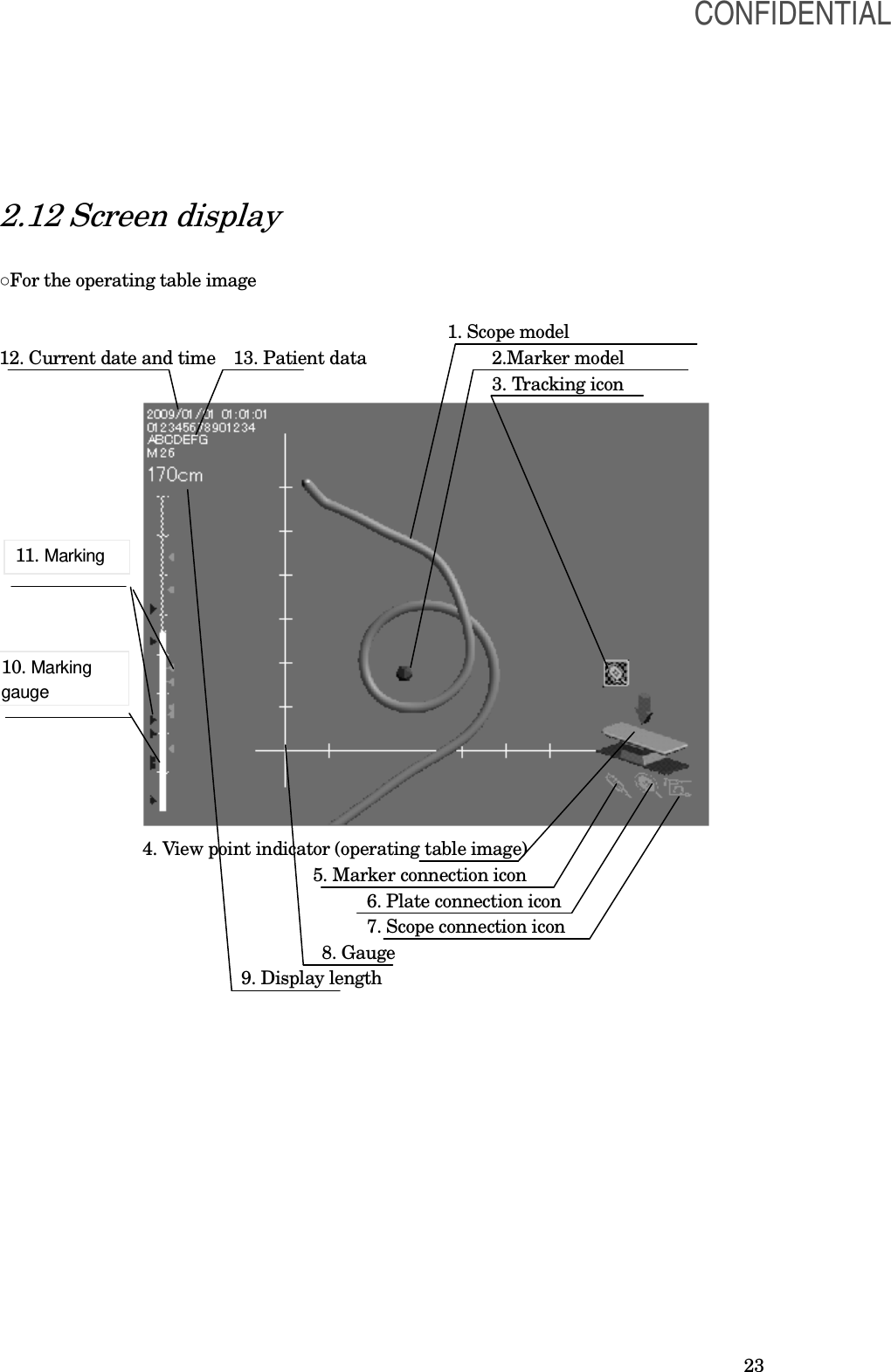
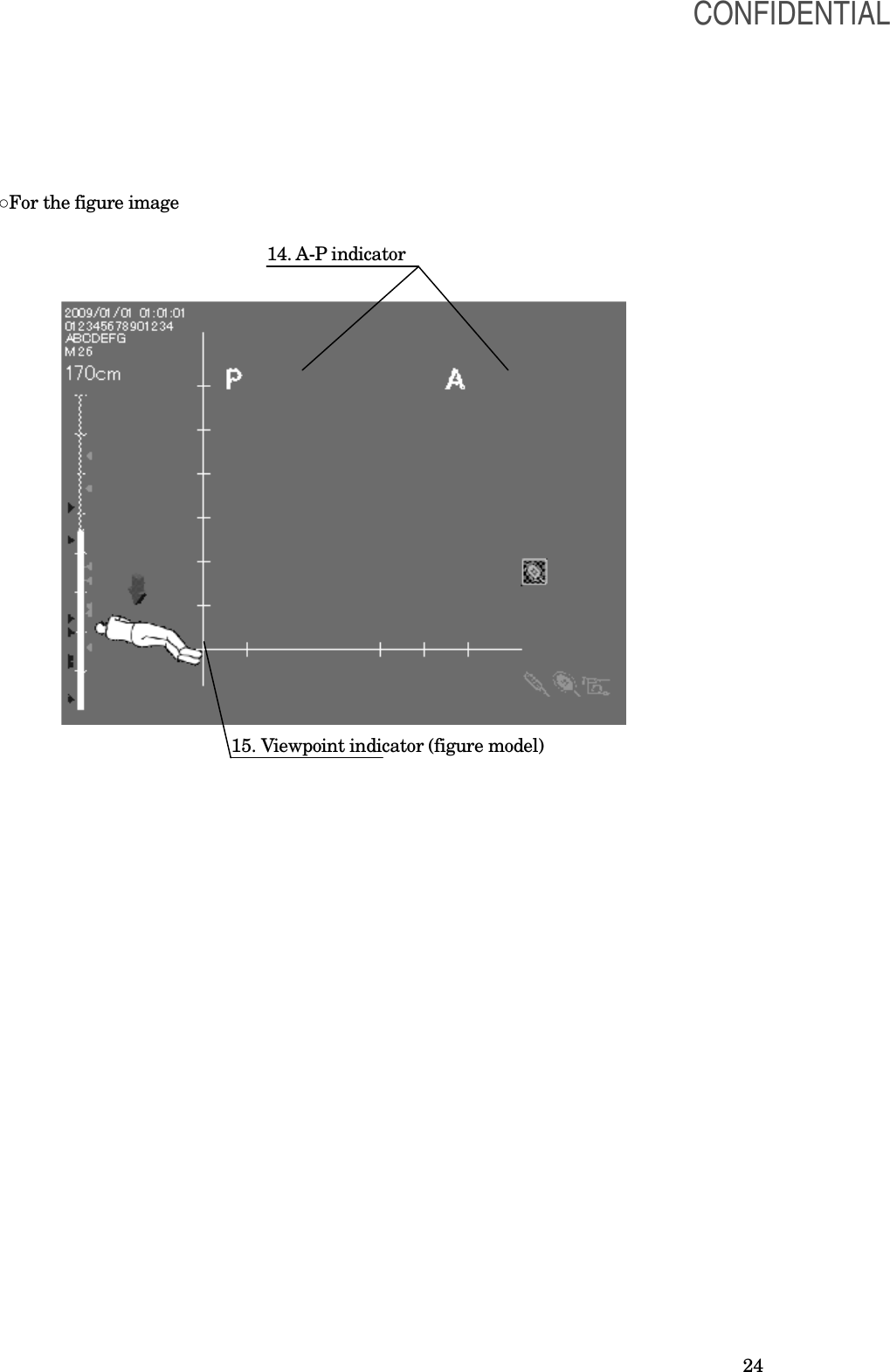
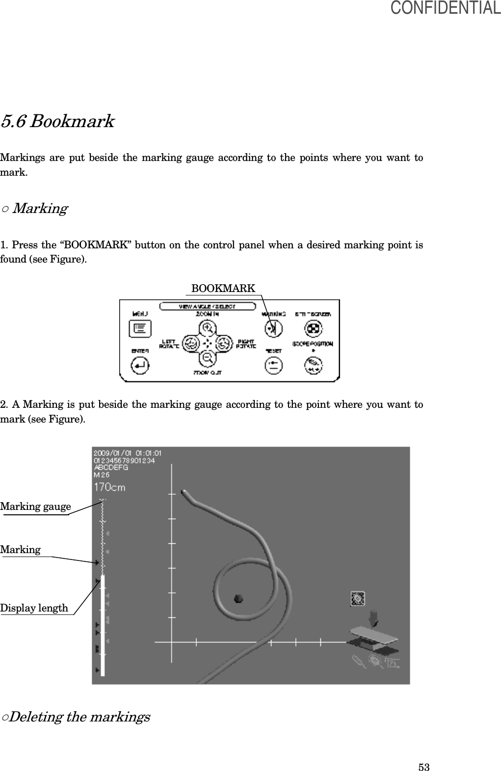
![26 11. Marking Markings can be put beside the marking gauge according to the points where you want to mark while inserting the endoscope into the patient. It will be displayed when “Enable information display” is set (see Section 5.6, “Bookmark”). 12. Current date and time Current date and time of the day will be displayed when “Enable information display” is set (see Section 8.3, “User preset”). 13. Patient data The data will be displayed when the video system center is connected and when “Enable information display” is set (see Section 8.3, “User preset”). 14. A-P indicator The indicator is displayed when “Figure image” is selected from “Setting the viewing image” in the setup menu. The indicator shows the anterior and posterior sides of the figure image. 15. Viewpoint indicator (Figure image) The arrow indicator and figure image show the angle in which the scope model on the screen is viewed. This indicator appears when “Figure image” is selected from “Setting the viewing image” in the setup menu (see Section 8.3, “User preset”). ○ Figure image The figure image is displayed when “Figure image” is selected from “Setting the viewing image” in the setup menu. The viewpoint indicator is displayed with a relative angle against the figure image on the screen. The posture of the figure image can be changed as the patient’s posture changes. [NOTE] The viewpoint indicator arrow shows the angle in which the scope model on the screen is viewed regardless of the posture of the figure image. The view angle is indicated against the receiver dish. CONFIDENTIAL](https://usermanual.wiki/Olympus-Medical-Systems/UPD-3.Instruction-Manual/User-Guide-1366365-Page-26.png)
![27 Chapter 3 Inspection [WARNING] Before each case, inspect this endoscope position detecting unit as instructed below. Inspect other equipment to be used with this endoscope position detecting unit as instructed in their respective instruction manuals. Should any irregularity be observed, do not use the endoscope position detecting unit and see Chapter 9, “Troubleshooting”. If the irregularity is still observed after consulting Chapter 9, contact Olympus. Damage or irregularities may compromise patient or user safety and may result in more severe equipment damage. Prepare the endoscope position detecting unit and other ancillary equipment before each particular case. Refer to the respective instruction manual for each piece of equipment. 3.1 Inspection work flow Please see the inspection work flow in Figure 3.1 below. Follow each step of the work flow for inspection of the light source before use. 1. Check if the endoscope position detecting unit is installed in an appropriate location.→ Section 3.2, “Inspection of the installation location” ↓ 2. Confirm that the endoscope position detecting unit is turned ON normally. → Section 3.3 “Turning power ON” ↓ 3. Confirm the contents in the screen display. → Section 3.4, “Inspection of the screen display” ↓ 4. Inspect all necessary functions. ↓ 5. Turn OFF the endoscope position detecting unit. → Section 3.7, “Power OFF” CONFIDENTIAL](https://usermanual.wiki/Olympus-Medical-Systems/UPD-3.Instruction-Manual/User-Guide-1366365-Page-27.png)
![28 3.2 Inspection of the installation location Check if the endoscope position detecting unit (UPD-3) is installed in an appropriate location. 1. Confirm that no video monitor or PC monitor is near the endoscope position detecting unit. Keep a distance of at least 30 cm between the video monitor or the PC monitor and the endoscope position detecting unit. [CAUTION] If a video monitor or PC monitor is located near the endoscope position detecting unit, the scope model display may be distorted or deformed due to the strong magnetic fields produced by the monitor. Keep the endoscope or the position detecting probe, the reference plate, and/or the hand coil connected with the main unit away from another main unit at least 2 m when two or more endoscope position detecting units are used. Otherwise, the scope model display may be extremely distorted or deformed due to the strong magnetic fields produced by one another. If the distance between the two endoscope position detecting units is less than 2 m, changing the frequencies used for position detection may allow the use of two or more endoscope position detecting units. When two or more endoscope position detecting units are used with a distance of less than 2 m, contact Olympus. 2. Confirm that no large metallic object is near the coil unit of the endoscope position detecting unit. Keep a distance of at least 30 cm between the large metallic object and the endoscope position detecting unit. [CAUTION] If a metallic object is located near the endoscope position detecting unit, the scope model display may also be distorted or deformed. 3.3 Turning power ON [WARNING] • Keep the endoscope or the position detecting probe, the reference plate, and/or the hand coil connected with the main unit away from another main unit at least 2 m when two or more endoscope position detecting units are used. Otherwise, the scope model display may be extremely distorted or deformed. • When two or more endoscope position detecting units are used, do not turn the main units ON at the same time. Otherwise, the scope model display may be extremely distorted or deformed. CONFIDENTIAL](https://usermanual.wiki/Olympus-Medical-Systems/UPD-3.Instruction-Manual/User-Guide-1366365-Page-28.png)
![29 1. Confirm that the ventilation grills on the right side and left side panels of the endoscope or the endoscope position detecting unit are not covered with dust or other materials. 2. Confirm that the endoscope or the position detecting probe is connected to the main unit. [NOTE] For connecting the endoscope or the position detecting probe to the main unit, refer to Section 4.4, “Connection of the endoscope or the position detecting probe”. 3. Press the power switch of the instrument. The power indicator lights up (see Figure). Power switch Power indicator ○ If the power fails to come ON If the power fails to come ON, turn the endoscope position detecting unit OFF. Then, confirm that the power cord is connected firmly. Then, turn the endoscope position detecting unit ON again. If the power still fails to come ON, contact Olympus. CONFIDENTIAL](https://usermanual.wiki/Olympus-Medical-Systems/UPD-3.Instruction-Manual/User-Guide-1366365-Page-29.png)
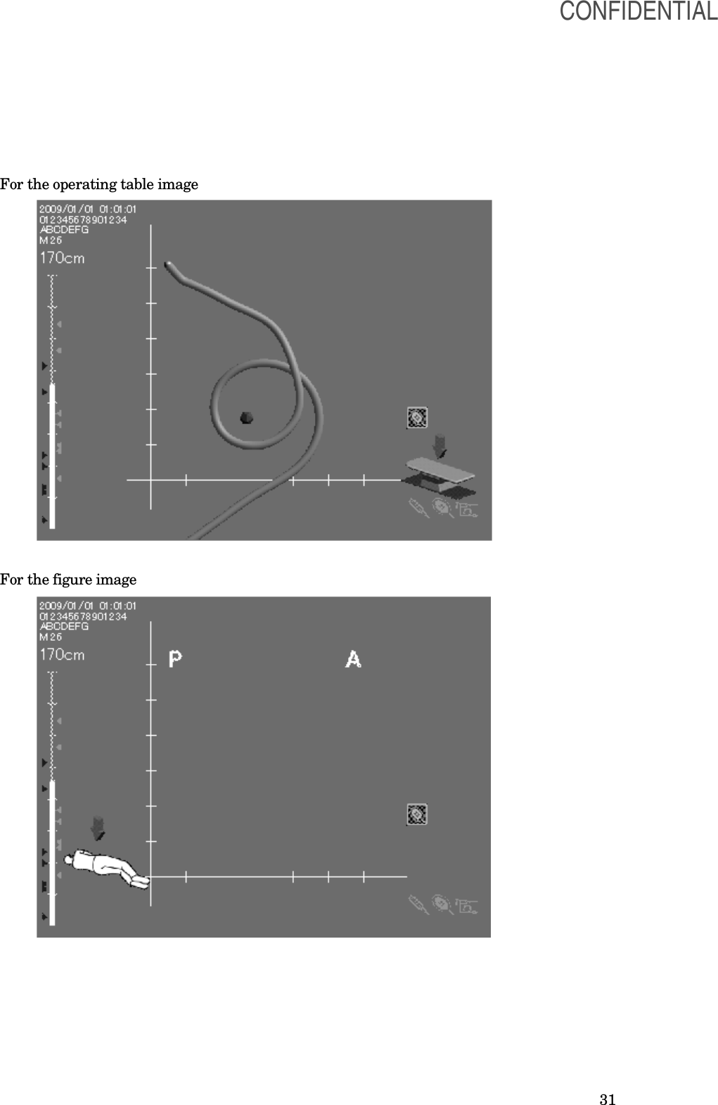
![30 3.4 Inspection of the screen display 1. Confirm that the LCD monitor shows the endoscope position display as shown in Figure. The screen display varies depending on the setup of the main unit or connection status of equipment. For details, see Section 2.12, “Screen display”. 2. Change the shape of the endoscope’s insertion tube or the position detecting probe’s insertion tube into a circular or straight shape in front of the coil unit of the endoscope position detecting unit. Then confirm that the shape of the scope model is the same as the shape of the endoscope’s insertion tube. Also, confirm that the angle of the viewpoint indicator is the same as the angle in which the scope model on the screen is viewed. Confirm that the shape of the scope model is the same as the shape of the endoscope’s insertion tube even when the receiver dish is facing down or up. 3. Confirm that the displayed date and time are correct. If correction is required, follow the procedure in “Setting the date and time” [CAUTION] The posture of the figure image on the screen must always be set to be equal to the actual posture of the patient. If the posture of the figure image on the screen is not equal to the posture of the patient, the scope model display may be incorrectly orientated. Facing down Facing up CONFIDENTIAL](https://usermanual.wiki/Olympus-Medical-Systems/UPD-3.Instruction-Manual/User-Guide-1366365-Page-30.png)
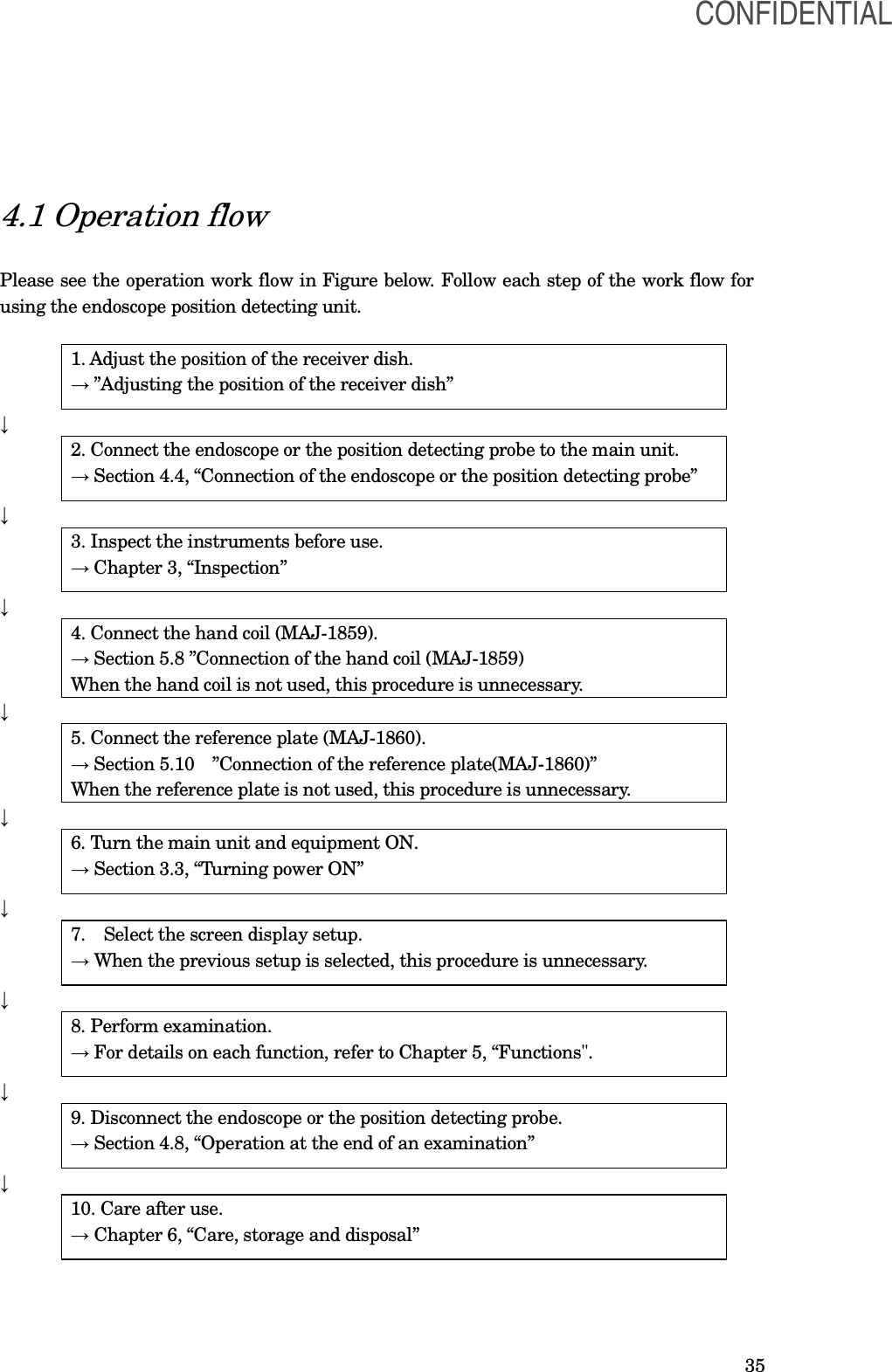
![33 Chapter 4 Operation This chapter explains the work flow of endoscopic observation using the endoscope position detecting unit. For information on how to use the functions that are not explained in this chapter, refer to chapter 5, “Functions”. The operator of the endoscope position detecting unit must be a physician or medical personnel under the supervision of a physician and must have received sufficient training in clinical endoscopic techniques. This manual, therefore, does not explain or discuss clinical endoscopic procedures. It only describes basic operation and precautions related to the operation of the endoscope position detecting unit. [DANGER] The endoscope position detecting unit is designed only to assist the insertion of an endoscope. Never insert the endoscope into the patient’s body by observing only the endoscope position display of the endoscope position detecting unit. Be sure to observe the endoscopic image and insert the endoscope while confirming safety. If the endoscope is inserted without observing the endoscopic image, patient injury could result. [WARNING] • Be sure to wear protective equipment such as eye wear, face mask, moisture-resistant clothing and chemical-resistant gloves that fit properly and are long enough so that your skin is not exposed. Otherwise, dangerous chemicals and/or potentially infectious material such as blood and/or mucus of the patient may cause an infection. • Anytime you observe an irregularity in this endoscope position detecting unit, stop using it immediately, turn it OFF, and solve the problem according to Chapter 9, “Troubleshooting”. If the problems cannot be resolved by the described remedial action, do not use this endoscope position detecting unit again and immediately contact Olympus. Using a defective endoscope position detecting unit may cause patient injury. • When the monitor display freezes, such as when the displayed time will not change or if the scope model will not move when the endoscope’s insertion tube is moved, or when the switches on the control panel are not accepted, turn the endoscope position detecting unit OFF and ON again. If the problem still occurs, contact Olympus. • When using spray-type medical agents such as lubricant, anesthetic, or alcohol, use them away from the endoscope position detecting unit so that the medical agents do not contact the endoscope position detecting unit. Medical agents might enter the endoscope position detecting unit through the ventilation grills and cause the failure. • Do not use a humidifier near the endoscope position detecting unit as dew condensation possibly might occur and it may cause the failure. • Use only Olympus high-frequency electrosurgical equipment with this unit. Non-Olympus equipment can cause interference on the monitor display or a loss of the scope model. CONFIDENTIAL](https://usermanual.wiki/Olympus-Medical-Systems/UPD-3.Instruction-Manual/User-Guide-1366365-Page-33.png)
![34 [CAUTION] • Do not use this endoscope position detecting unit in locations exposed to strong electromagnetic radiation (e.g., in the vicinity of microwave therapeutic equipment, MRI, short-wave therapeutic equipment, radio equipment, or cellular/portable phone). Damage to the endoscope position detecting unit may result. Electromagnetic radiation can interfere with the monitor display. • When the endoscope position detecting unit is used on a patient with an artificial material implant, the displayed scope model shape may differ from its actual shape. • Do not approach the following equipment with a magnetic storage medium (magnetic card, floppy disk, etc.): the endoscope, the position detecting probe, the reference plate (MAJ-1859), or the hand coil (MAJ-1860) connected to the endoscope position detecting unit. Otherwise, the data stored on the magnetic storage medium may be destroyed or lost due to the AC magnetic fields generated by these devices. CONFIDENTIAL](https://usermanual.wiki/Olympus-Medical-Systems/UPD-3.Instruction-Manual/User-Guide-1366365-Page-34.png)
![41 4.3 Adjusting the position of the receiver dish [WARNING] •When adjusting the height of the receiver dish, or when adjusting the height of the operating table if it is adjustable, be careful not to have your hand, foot, or the patient’s body caught between the receiver dish and the operating table. Otherwise, operator and/or patient injury may result. Be careful not to have your fingers caught between the arms when they are closed. Operator and patient injury may result. Do not allow the patient to hold the receiver dish or receiver dish stand. Otherwise, the stand may be toppled, and patient injury may result. [CAUTION] Keep the receiver dish at the same height as the patient’s body. If the distance between the patient’s body and the receiver dish is too large, the scope model may be displayed incorrectly. 1. Adjust the position of the receiver dish. CONFIDENTIAL](https://usermanual.wiki/Olympus-Medical-Systems/UPD-3.Instruction-Manual/User-Guide-1366365-Page-41.png)
![42 4.4 Connection of the endoscope or the position detecting probe Connect the endoscope to the endoscope position detecting unit (UPD-3) by using the UPD cable (MAJ-1881). [WARNING] Do not place the UPD cable on the operating table. This could result in an infection when the patient contacts the UPD cable. Also, the scope model display may become distorted or deformed. [CAUTION] • Always turn the endoscope position detecting unit OFF before connecting or disconnecting the UPD cable. Otherwise, equipment damage or malfunction may result. • Do not apply excessive force to the UPD cable; it may cause equipment damage. • Do not immerse the UPD cable in liquids or allow it to become wet; it may cause equipment damage or malfunction. • Do not touch the electrical contacts inside the endoscope position detecting unit’s connectors; ○Connecting the UPD cable to the endoscope Align the notch on the endoscope plug of the UPD cable with mark 3 on the UPD scope connector of the endoscope and push the endoscope plug into the UPD scope connector until it stops (see Figure). [NOTE] If force is used on the UPD cable, the endoscope is designed to detach at the endoscope plug, not at the endoscope connector. CONFIDENTIAL](https://usermanual.wiki/Olympus-Medical-Systems/UPD-3.Instruction-Manual/User-Guide-1366365-Page-42.png)
![43 ○Connecting the UPD cable to the position detecting probe 1. Holding the electrical connector of the position detecting probe and the connector of the UPD cable connected to the endoscope position detecting unit, align the index on the position detecting probe’s electrical connector with the notch on the UPD cable’s position detecting connector, and connect them (see Figure).. 4.5 Turning power ON [WARNING] When two or more endoscope position detecting units are used, do not turn the main units ON at the same time. Otherwise, the scope model. Press the power switch to turn ON the endoscope position detecting unit, confirm that the power indicator on the main unit is lit (see Figure). Power switch Power indicator 4.6 Starting the endoscopic examination 1. Confirm the direction in which the endoscope is pointing by checking the viewpoint indicator arrow. When the viewpoint indicator arrow is selected not to be displayed, press the “Enter” button to display it. [NOTE] CONFIDENTIAL](https://usermanual.wiki/Olympus-Medical-Systems/UPD-3.Instruction-Manual/User-Guide-1366365-Page-43.png)
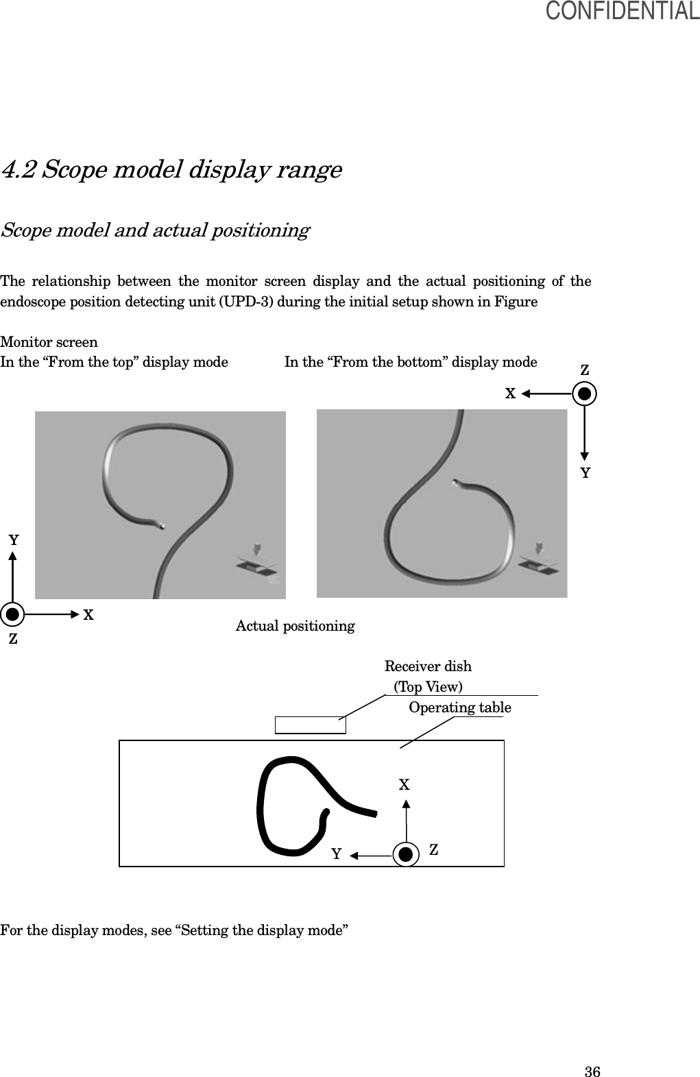
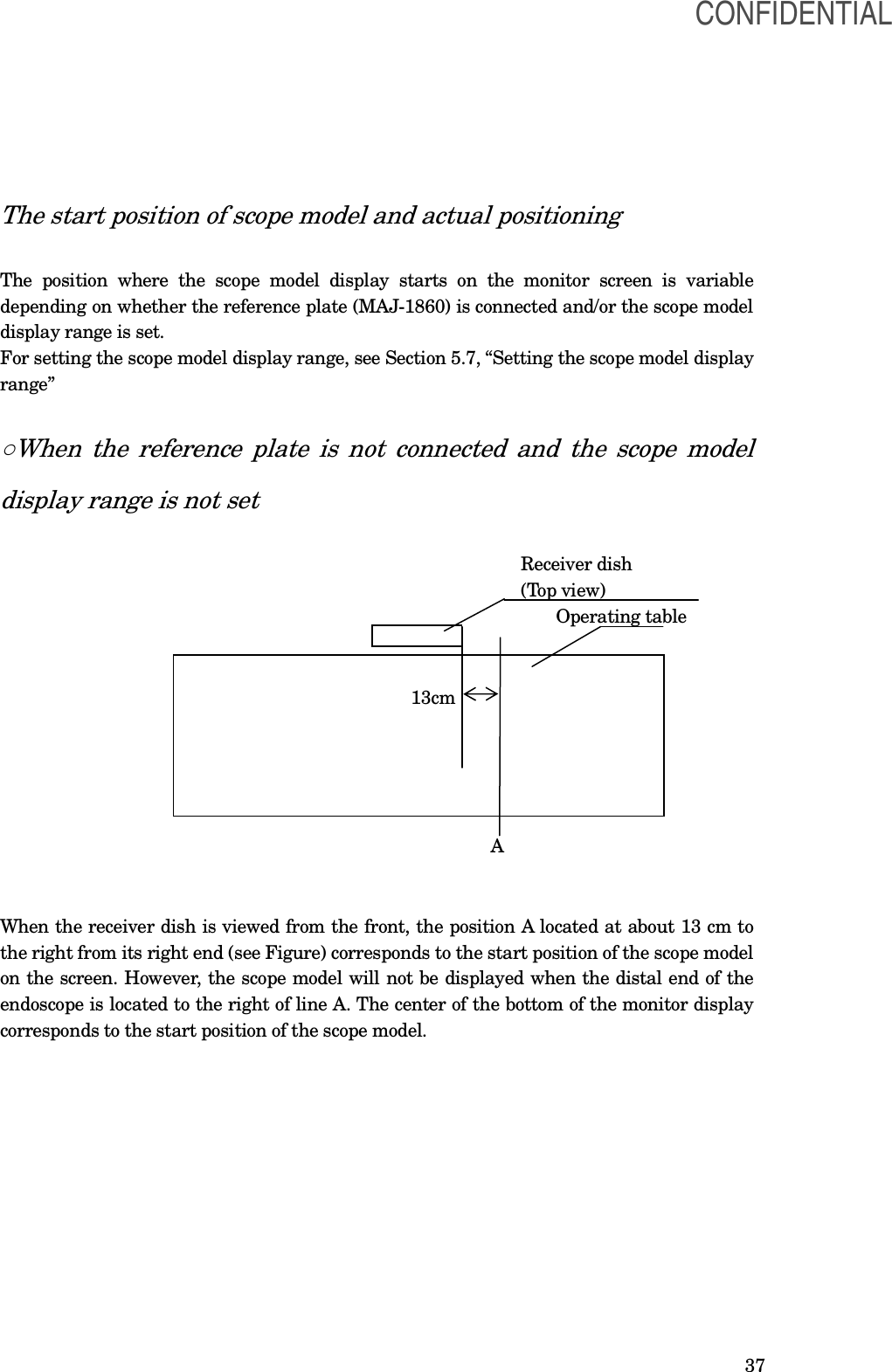
![44 For setting the viewpoint indicator arrow, refer to ○Viewpoint indicator arrow” 2. Start the endoscopic examination as indicated in the instruction manual for the endoscope in use. [NOTE] For the start position of the scope model, refer to Section 4.2, “Scope model display range” 4.7 Displaying the scope model The scope model is displayed as described below. • Gray scale: The shape of the endoscope is represented as a gray cylinder. The areas near the viewpoint are displayed in bright gray and those apart from the viewpoint are displayed in dark gray. • Distal end display: The section corresponding to the distal end of the endoscope is represented by a yellow sphere. • Colors Color Function Gray Stable section Yellow • Parts of the endoscope that are located outside of the detection area. • Section where the shape of the scope model is not accurate. • Section where a stable shape of the scope model cannot be displayed. Red Parts of the endoscope, parts of the position detecting probe, or the UPD cable (MAJ-1881) broke down. Translucent The area from the proximal end of the insertion tube to the start position of the scope model where the whole insertion tube of the endoscope is within the left side from the start position of the scope model. Not displayed • Because the insertion tube of the endoscope is too close or too far from the coil unit, the coil unit is unable to detect the endoscope. • The distal end of the endoscope is outside the detection range. [NOTE] • The areas displayed in yellow, red, and/or translucent should be regarded as incorrect because their accuracy is low. • If the endoscope, the position detecting probe, or UPD cable (MAJ-1881) fails in the middle of the examination, the scope display area corresponding to the failed section is displayed in red. When the endoscope position detecting unit is turned OFF and then ON again, the error message will appear. • Wavering: The scope model display may waver sometimes. This is not a malfunction. CONFIDENTIAL](https://usermanual.wiki/Olympus-Medical-Systems/UPD-3.Instruction-Manual/User-Guide-1366365-Page-44.png)
![45 • Fusion: When different sections of the insertion tube of the endoscope come close to each other, the overlapped areas in the scope model display may be shown as if they are fused (see Figure). • Overlapping of intersected sections: When different sections of the insertion tube of the endoscope become close to each other, the intersected areas in the scope model display may be shown upside down or in an inaccurate shape. [WARNING] If the insertion tube of the endoscope forms a loop during an examination, and the overlapped areas in the scope model display may be shown as if they are fused, the intersected areas may be shown upside down or in an inaccurate shape. In such a case, dissolve the fusion in the display by moving the endoscope slightly while observing the scope model display to undo the loop of the insertion tube. It is also possible to correct the way the overlapped areas of the insertion tube are displayed and then undo the loop if the current status requires it. If you attempt to undo the loop of the insertion tube by observing the scope model display while the overlapped areas in it are shown as fused or in an inaccurate shape, patient injury could result. Influence of electromagnetic radiation This instrument which utilizes weak AC magnetic fields is subject to electromagnetic radiation (noise). To reduce the influence of electromagnetic radiation, this instrument performs the following: ○Selection of frequencies for use This instrument automatically selects frequencies of AC magnetic fields for use. After measuring the noise levels at predetermined three frequencies, this instrument selects a frequency generating the lowest noise level at powering ON this instrument. CONFIDENTIAL](https://usermanual.wiki/Olympus-Medical-Systems/UPD-3.Instruction-Manual/User-Guide-1366365-Page-45.png)
![46 [NOTE] Fixing the frequency to use is also possible. See Section 8.2 “System setup”. ○Selection of display speed Under the environment with high level noise, the scope model will be displayed at lower speed so that this instrument can get enough signals. After measuring the noise levels, this instrument selects speed to display the scope model at powering ON. [NOTE] - If the scope model display wavers significantly or becomes unstable when operating the endoscope position detecting unit, the cause may be increased external noise. In that case, bring the receiver dish to the patient as close as possible. If no improvement is observed, turn the endoscope position detecting unit OFF and turn it ON again. - Fixing the display speed is also possible. See Section 8.2 “System setup”. 4.8 Operation at the end of an examination 1. Turn the endoscope position detecting unit and ancillary equipment OFF. 2. Disconnect the UPD cable (MAJ-1881) from the endoscope. 3. Disconnect the hand coil (MAJ-1859) and reference plate (MAJ-1860) from the endoscope position detecting unit. [CAUTION] Be sure to turn the endoscope position detecting unit OFF before connecting or disconnecting the UPD cable, reference plate, and hand coil to or from the endoscope position detecting unit. Otherwise, the endoscope, endoscope position detecting unit, reference plate, and/or hand coil may be damaged. 4. Remove the reference plate cover (MAJ-1880) from the reference plate. CONFIDENTIAL](https://usermanual.wiki/Olympus-Medical-Systems/UPD-3.Instruction-Manual/User-Guide-1366365-Page-46.png)
![47 Chapter 5 Functions This chapter describes functions of the buttons of main unit and usage of the hand coil and the reference plate. Before use, refer to the “Function setup” for functions that need to be set in “System setup” and “User preset”. 5.1 Rotating the scope model The scope model can be rotated as required. [WARNING] Make sure to match the posture of the figure image with that of the patient. Improper operation due to a mismatch between the posture of the patient, the actual endoscope position in the patient cavity, and the position displayed on the UPD screen may result in patient injury and/or perforation. Press the “Rotate left” or “Rotate right” button on the control panel (see Figure). The scope model will be rotated as shown in Figure. Rotate left Rotate right [NOTE] • After the settings are completed, the setup is held in memory even after the endoscope position detecting unit is turned OFF. The previous setup will be recalled the next time the unit is turned ON. • The rotation angle of the scope model can be saved and recalled as described in “User preset” • The viewpoint indicator arrow on the screen shows the direction in which the scope model is viewed. For showing the arrow, refer to ○Viewpoint indicator arrow” • Pressing the reset switch recalls the rotation angle that has been saved in the previous “Saving and recalling the display setup” operation. • By rotating the scope model, there may be space between the start position of the scope model and the bottom of the screen. CONFIDENTIAL](https://usermanual.wiki/Olympus-Medical-Systems/UPD-3.Instruction-Manual/User-Guide-1366365-Page-47.png)
![48 • By rotating the scope model, the scope model may be out of the screen. For redisplaying the scope model, press the reset switch. 5.2 Varying the size of the scope model The size of the scope model as well as the sizes of the marker and gauge can be varied as described below. [NOTE] • With the initial setup, the zooming ratio is set to the middle ratio. • After this setup is completed, the settings are held in memory even after the endoscope position detecting unit is turned OFF. The previous setup will be recalled the next time the unit is turned ON. • The zooming ratio of the scope model can be saved and recalled as described in Section 8.3 “User preset.” • By zooming in the scope model, the scope model may be hidden from view. For redisplaying the scope model, press the reset switch. • Pressing the reset switch recalls the zooming ratio that has been saved in the previous “ ” operation. Press the “ZOOM IN” or “ZOOM OUT” button on the control panel (see Figure). The scope model will be zoomed in or out (i.e., magnified or reduced) as shown in Figure. ZOOM IN ZOOM OUT CONFIDENTIAL](https://usermanual.wiki/Olympus-Medical-Systems/UPD-3.Instruction-Manual/User-Guide-1366365-Page-48.png)
![49 5.3 Splitting the screen The scope model can be displayed on two screens by splitting the screen. [NOTE] After this setup is completed, the settings are held in memory even after the endoscope position detecting unit is turned OFF. The previous setup will be recalled the next time the unit is turned ON. Each press of the split screen button on the control panel changes the split-screen display and single-screen display alternately (see Figure). SPLIT SCREEN Splitting the screen for the operating table image Single-screen display Split-screen display [NOTE] • One screen shows the single screen display and the other shows the single screen view as well as the 90° rotated view in the split screen. • The view angles in the right and left sides of the split screen are indicated by the viewpoint indicator of the operating table image in each screen. • By pressing the split screen switch, the scope model is redisplayed so that the center of the top or bottom of the split screen corresponds with the start position of the scope model. CONFIDENTIAL](https://usermanual.wiki/Olympus-Medical-Systems/UPD-3.Instruction-Manual/User-Guide-1366365-Page-49.png)
![50 Splitting the screen for the figure image Single-screen display Split-screen display [NOTE] • The screen with the view angle selected from the menu is displayed. • The view angles on the right and left sides of the split screen are indicated by the A-P indicator and the figure image respectively. • By pressing the split screen switch, the scope model is redisplayed so that the center of the top or bottom of the split screen corresponds CONFIDENTIAL](https://usermanual.wiki/Olympus-Medical-Systems/UPD-3.Instruction-Manual/User-Guide-1366365-Page-50.png)
![51 5.4 Resetting the setup Pressing the reset switch resets the settings made in the previous “User preset” operation. When no operations are made in the Section 8.3 “User preset”, the factory default settings are recalled. 1. Press the reset button (see Figure). RESET 2. The following settings are reset to the settings made in the previous “User preset” operation. • Viewing image selection • Figure image and view angle (for the figure image selection) • View indicator arrow (for the figure image selection) • A-P indicator selection (for the figure image selection) • Display mode selection • Scope model thickness setup • Information display selection • Rotation angle of scope model (for the operating table image selection) or posture of the figure image (for the figure image selection) • Zooming ratio of scope model [NOTE] • By pressing the reset switch, the scope model is redisplayed so that the center of the bottom of the screen corresponds with the start position of the scope model. CONFIDENTIAL](https://usermanual.wiki/Olympus-Medical-Systems/UPD-3.Instruction-Manual/User-Guide-1366365-Page-51.png)
![54 1. Press the “BOOKMARK” button on the control panel awhile (see Figure). 2. All markings are deleted. [NOTE] •The markings are shown based on the display length. They may not correspond to the position in the actual intestinal tract. •Markings can be put every 1 cm. •Close markings may be shown as one. •The same position cannot be marked. •Up to 50 markings can be put beside the marking gauge. The error message will be displayed when more than 50 markings are marked. •All markings are deleted automatically under the following cases. - When the main unit is turned OFF. - When the UPD cable (MAJ-1881) is disconnected from the endoscope or the position detecting probe. 5.7 Setting the scope model display range When the scope model display range is set, the scope model display outside the range will be erased. [NOTE] • After this setup is completed, the settings are held in memory even after the endoscope position detecting unit is turned OFF. The previous setup will be recalled if the hand coil is connected the next time the unit is turned ON. • Even when the unit is turned OFF while the display range is set, the display range setup is canceled if the hand coil is not connected the next time the unit is turned ON. • The scope model is redisplayed so that the center of the bottom of the screen corresponds with the start position of the scope model. • When the tracking indicator disappears even if the reference plate is connected, the scope model display range cannot be set. • The setup of the scope model display range is canceled by disconnecting the hand coil when the scope model display range is set. ○When using the hand coil (MAJ-1859) [NOTE] • When the marker connection indicator is yellow, the scope position switch does not work. For connecting the hand coil, refer to “Connection of the hand coil (MAJ-1859) . CONFIDENTIAL](https://usermanual.wiki/Olympus-Medical-Systems/UPD-3.Instruction-Manual/User-Guide-1366365-Page-54.png)
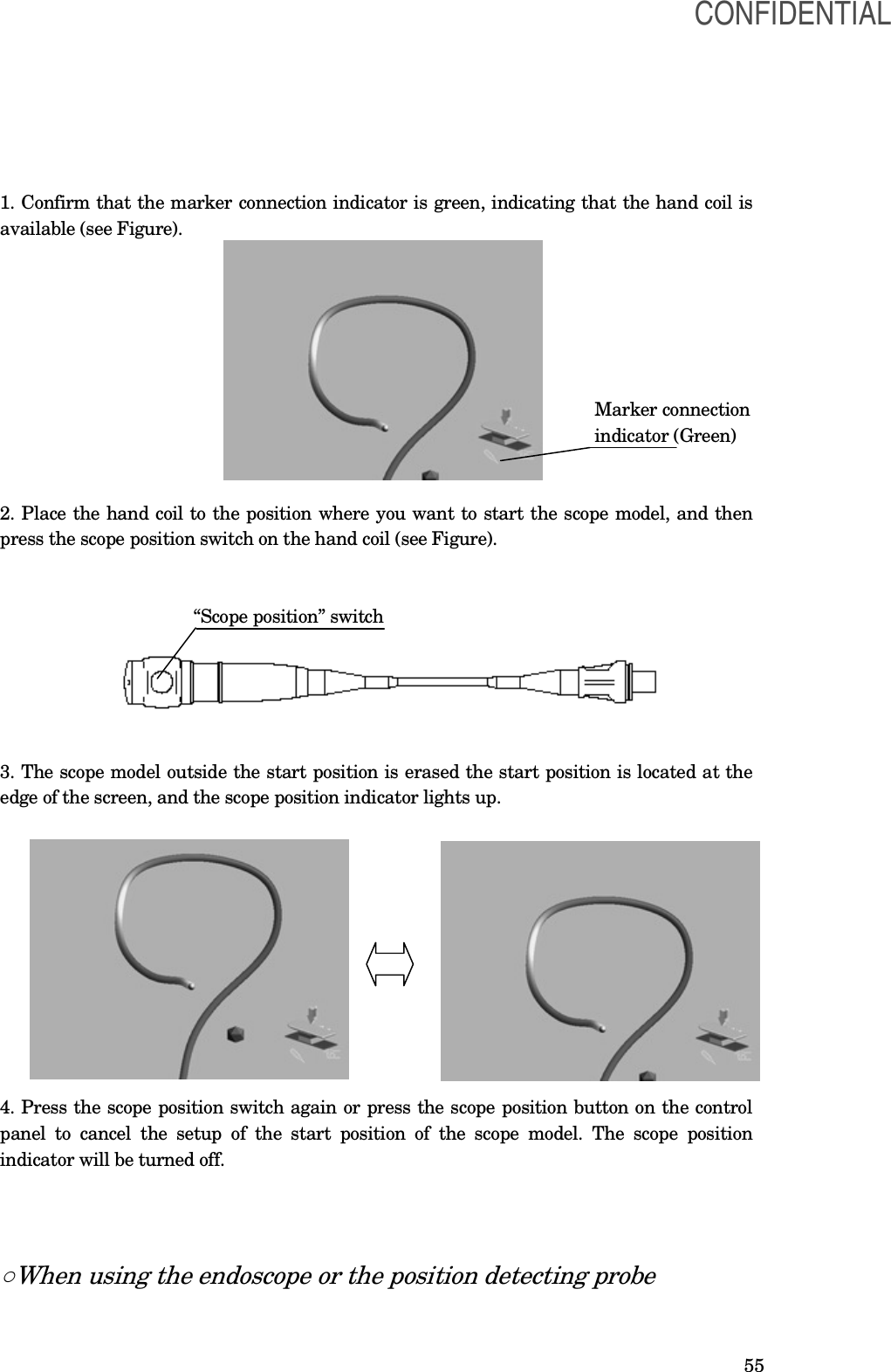
![56 1. Place the distal end of the endoscope or the position detecting probe to the position where you want to start displaying the scope model, and then press the "SCOPE POSITION" button on the control panel (see Figure). Scope position indicator Scope position 2. The scope model outside the start position is erased, the start position is located at the edge of the screen, and the scope position indicator lights up. 3. Press the scope position button again to cancel the setup of the start position of the scope model. The scope position indicator will be turned off. [NOTE] For the start position of the scope model, refer to Section 4.2, “Scope model display range”. 5.8 Connection of the hand coil (MAJ-1859) Connect the hand coil when it will be used. [WARNING] •Avoid bringing the hand coil or hand coil cover in contact with the skin of the operator and/or patient. Otherwise, infection of the patient and/or operator may result. [CAUTION] •Connect the hand coil to either the main unit or the connection unit (MAJ-Y0093). Otherwise, it does not operate. 1. Contact the hand coil with its arrow mark on the plug facing upwards with the hand coil terminal on the main unit (see Figure). CONFIDENTIAL](https://usermanual.wiki/Olympus-Medical-Systems/UPD-3.Instruction-Manual/User-Guide-1366365-Page-56.png)
![57 2. Hold the plug and insert it straight to the hand coil terminal until it clicks 3. Fit the hand coil cover around the hand coil (see Figure). 4. When the hand coil becomes necessary during examination, the operator should hold it in his or her hand (see Figure). [NOTE] For details on the hand coil function, refer to Section 4.2 “Scope model display range” and CONFIDENTIAL](https://usermanual.wiki/Olympus-Medical-Systems/UPD-3.Instruction-Manual/User-Guide-1366365-Page-57.png)
![58 “Setting the scope model display range”. 5. To disconnect the hand coil, hold the connecting section of the connector and pull it straight out (see Figure). 5.9 View tracking When the reference plate (MAJ-1860) is used, the rotation of the scope model is controlled by the reference plate. When the reference plate is attached to the patient’s body, any rotation of the patient will accordingly cause a rotation of the scope model (view tracking). Confirm that the reference plate connection indicator is green. In this condition, the scope model display changes to the tracking display and the tracking. Tracking indicator Plate connection indicator [NOTE] •When the tracking indicator disappears while attaching the reference plate to the patient, the scope model cannot be tracked. In this case, move the patient near the coil unit to display the tracking indicator. •For usage of the reference plate, refer to “Connection of the reference plate (MAJ-1860) CONFIDENTIAL](https://usermanual.wiki/Olympus-Medical-Systems/UPD-3.Instruction-Manual/User-Guide-1366365-Page-58.png)
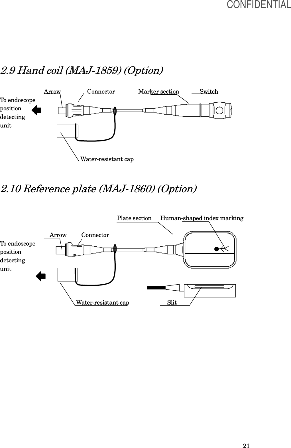
![59 and “Attaching the reference plate (MAJ-1860) to the patient’s body”. 5.10 Connection of the reference plate (MAJ-1860) Connect the reference plate when the tracking function is required (see Section 5.9, “View tracking”). Disconnect the reference plate when the tracking function is not required. [CAUTION] •Connect the reference plate to either the main unit or the connection unit (MAJ-1928). Otherwise, it does not operate. 1. Insert the reference plate with its arrow on the connector facing upwards to the reference plate connector on the main unit (see Figure). 2. Hold the connector and insert it straight to the reference plate connector until it clicks. 3. To disconnect the reference plate, hold the connecting section of the connector and pull it straight out (see Figure). CONFIDENTIAL](https://usermanual.wiki/Olympus-Medical-Systems/UPD-3.Instruction-Manual/User-Guide-1366365-Page-59.png)
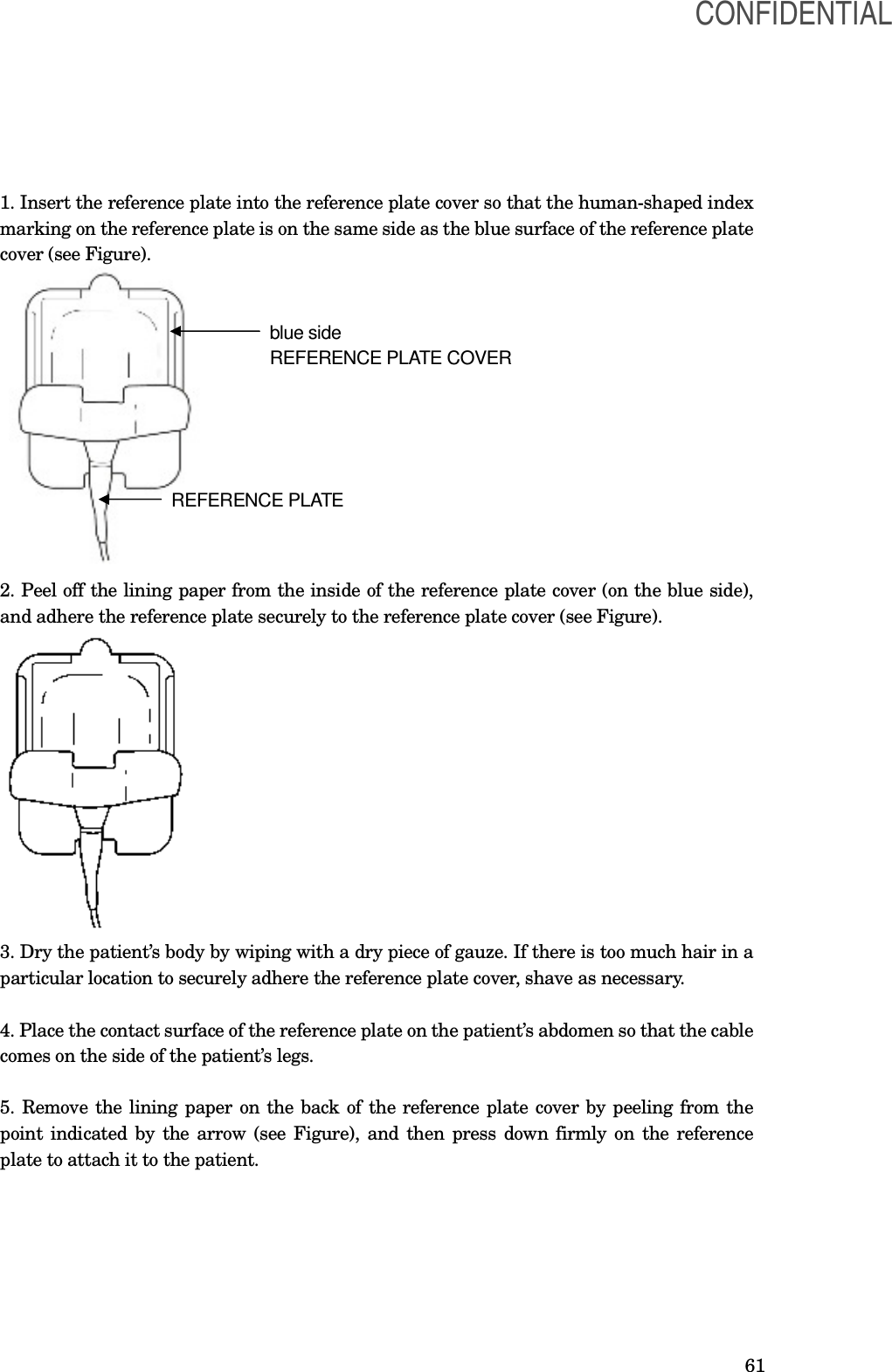
![60 5.11 Attaching the reference plate (MAJ-1860) to the patient’s body [WARNING] • Avoid bringing the reference plate, reference plate cover, and reference plate belt (MAJ-1029) in contact with the skin of the operator and/or patient. Otherwise, an infection may result. [CAUTION] • Attach the reference plate parallel to the back of the patient and fit the central axis of the reference plate to the patient’s central axis. Otherwise, the scope model may disappear during the examination, may not be displayed, or may be incorrectly displayed. • Attach the reference plate properly to the patient’s body. Otherwise, the scope model will not be displayed correctly. − If the reference plate is attached in a manner that the slit contacts the patient’s abdomen, the scope model display will reverse the left and right. − If the reference plate is attached so that the cable comes on the side of the patient’s feet, the scope model display may be shown upside down, or may not be shown at all. [NOTE] For details on the reference plate function, refer to the “View tracking”. ○When the reference plate cover (MAJ-1880) is used [CAUTION] • Patients with allergies may experience reddening or irritation of the skin caused by the adhesive on the antenna lead covers. • Use a reference plate cover before expiration date. Otherwise, the reference plate may not be securely adhered to the patient’s body. The expiration date of the reference plate cover is shown on the package. CONFIDENTIAL](https://usermanual.wiki/Olympus-Medical-Systems/UPD-3.Instruction-Manual/User-Guide-1366365-Page-60.png)
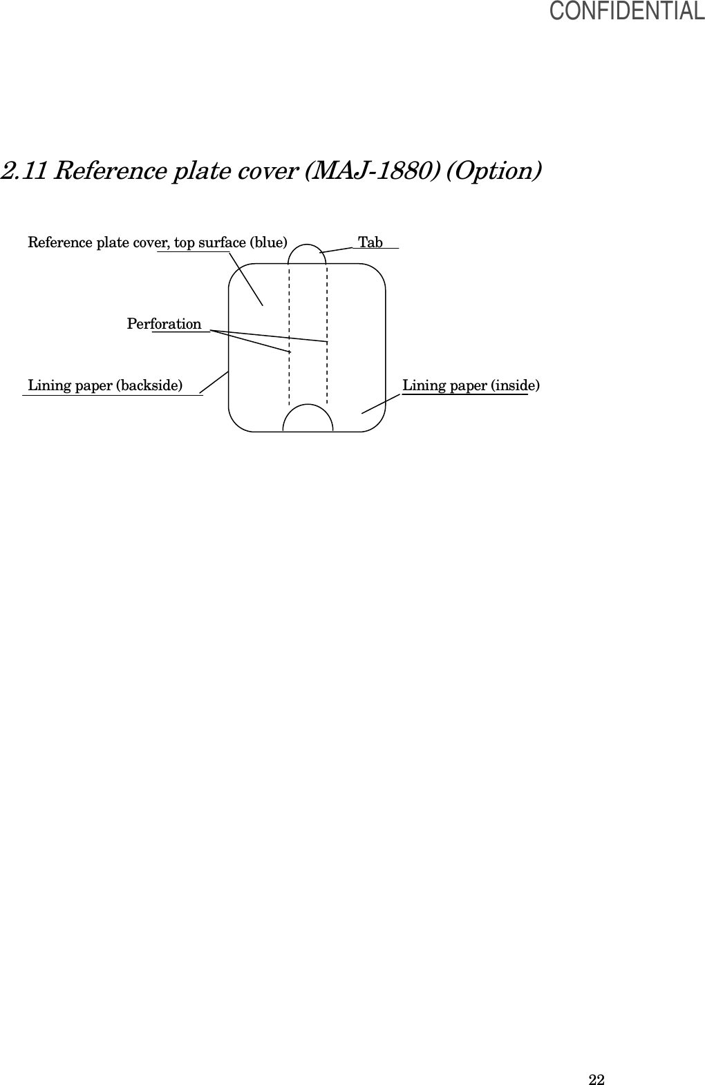
![62 [CAUTION] The reference plate cover used before has lost its adhesiveness. When reattaching the reference plate, replace the cover with a new one. ○Removing the reference plate cover from the reference plate 1. Remove the reference plate from the reference plate covers. The reference plate cover can be easily removed by holding the tab and tearing the center section 2. Carefully remove the reference plate cover from the patient. [CAUTION] Do not fold or crease the reference plate when removing it from the reference plate cover. Otherwise, the reference plate may be damaged. [NOTE] CONFIDENTIAL](https://usermanual.wiki/Olympus-Medical-Systems/UPD-3.Instruction-Manual/User-Guide-1366365-Page-62.png)
![63 The reference plate covers are single-use only. ○When the reference plate cover (MAJ-1880) is not used 1. Pass the reference plate belt through the slit (see Figure). 2. Place the contact surface of the reference plate on the patient’s abdomen and align the orientation of the patient’s body with that of the human-shaped index marking of the reference plate so that the cable comes on the side of the patient’s foot. 3. Wrap the reference plate belt around the patient’s body and fasten the reference plate using the surface fastener on the reference plate belt. [CAUTION] • Do not tighten the reference plate belt too much. Excessive tightening can cause patient pain. • Attach the reference plate belt firmly around the patient’s body so that the reference plate will not move. Otherwise, the scope model display will be unstable. CONFIDENTIAL](https://usermanual.wiki/Olympus-Medical-Systems/UPD-3.Instruction-Manual/User-Guide-1366365-Page-63.png)
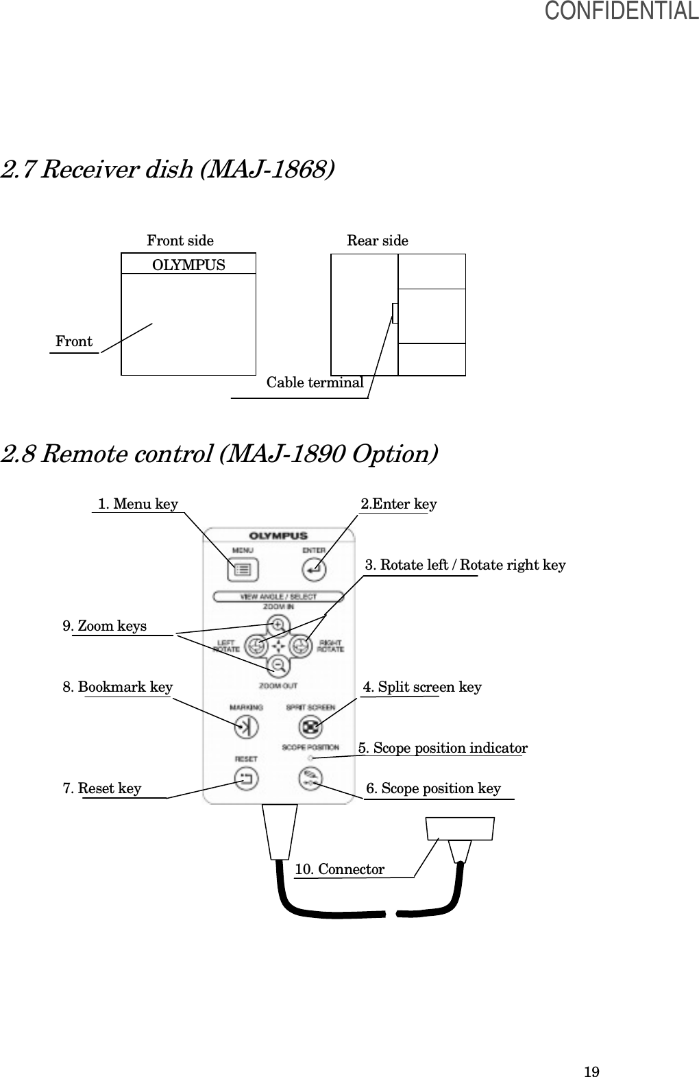
![64 5.12 Operation using the remote control The remote control (MAJ-1890) can operate the same function as the control panel does. [CAUTION] • Do not use a pointed or hard object to press the keys on the remote control. This may damage the keys. •Properly install the remote control. If it is not properly installed, the remote control may be damaged. Install the remote control on a stable, level surface so that the cable between the endoscope position detecting unit and remote control is not stretched. •When operating the remote control, hold the control not the cable. Otherwise, the cable may break. •Do not fix the cable using surgical clamps, such as Pean, because the cable may break. For displaying the scope model, refer to the “Setting the scope model display range”. [NOTE] For connecting the remote control, refer to Section 7.7, “Remote control.”. CONFIDENTIAL](https://usermanual.wiki/Olympus-Medical-Systems/UPD-3.Instruction-Manual/User-Guide-1366365-Page-64.png)
![65 Chapter 6 Care, Storage, and Disposal 6.1 Care If the endoscope position detecting unit and accessories are soiled, perform the following cleaning procedure immediately after use. If cleaning is delayed, residual organic debris will begin to solidify, and it may be difficult to effectively clean the endoscope position detecting unit. The endoscope position detecting unit should also be cleaned routinely. [WARNING] After cleaning the main unit and accessories, dry them thoroughly before use. If they are used while still wet, there is the risk of electric shock. [CAUTION] • Do not clean the output connector, the terminals, or the AC power mains inlet. Cleaning them can deform or corrode the contacts, which could damage the endoscope position detecting unit. • Do not autoclave or gas sterilize the endoscope position detecting unit. These methods will damage it. • The UPD cable is not waterproof and should not be cleaned together with the endoscope. Otherwise, the equipment will malfunction. • Do not wipe the external surface with hard or abrasive material. The surface will be scratched. • Alcohol is flammable. Handle with care. CONFIDENTIAL](https://usermanual.wiki/Olympus-Medical-Systems/UPD-3.Instruction-Manual/User-Guide-1366365-Page-65.png)
![66 ○Compatible reprocessing methods and chemical agents Compatibility summary The instruments shown below are compatible with several methods of reprocessing. For appropriate reprocessing methods, refer to Table below, the recommendations of your infection control committee, and all national and local hospital guidelines and policies. 70% ethyl or isopropyl alcohol Detergent solution Hand coil (MAJ-1859) Hand coil cover (MAJ-1879) Reference plate (MAJ-1860) compatible not compatible [WARNING] Alcohol is not a sterilant or high-level disinfectant. ○Detergent solution Use a medical-grade, low-foaming, neutral pH detergent, or enzymatic detergent and follow the manufacturer’s dilution and temperature recommendations. Contact Olympus for the names of specific brands that have been tested for compatibility with these instruments. Do not reuse detergent solutions. [WARNING] Excessive detergent foaming can prevent fluid from adequately contacting components. ○Care of the hand coil (MAJ-1859), hand coil cover (MAJ-1879), and reference plate (MAJ-1860) 1. Turn the endoscope position detecting unit OFF and disconnect the power cord. 2. To remove dust and dirt on the respective accessories, wipe them using a lint-free cloth moistened with neutral detergent. 3. If the accessories are soiled with patient blood or debris, wipe off all gross debris using neutral detergent and then decontaminate their surfaces using a lint-free cloth moistened CONFIDENTIAL](https://usermanual.wiki/Olympus-Medical-Systems/UPD-3.Instruction-Manual/User-Guide-1366365-Page-66.png)
![67 with 70% ethyl or isopropyl alcohol or follow the instructions described in Section 6.2 “Cleaning procedures for accessories. 4. Make sure that the accessories are completely dry after wiping. ○Care of the main unit and accessories other than the hand coil (MAJ-1859), hand coil cover (MAJ-1879), and reference plate (MAJ-1860) 1. Turn the endoscope position detecting unit OFF and disconnect the power cord. 2. To remove dust and dirt on the main unit and accessories, wipe them using a lint-free cloth moistened with neutral detergent. 3. If the accessories are soiled with patient blood or debris, wipe off all gross debris using neutral detergent and then decontaminate their surfaces using a lint-free cloth moistened with 70% ethyl or isopropyl alcohol. 4. Make sure that the accessories are completely dry after wiping. 6.2 Cleaning procedures for accessories This section includes the cleaning procedures for the accessories and reprocessing equipment listed below. •Hand coil (MAJ-1859) •Hand coil cover (MAJ-1879) •Reference plate (MAJ-1860) ○Attaching the water-resistant cap (MAJ-1899) [CAUTION] • The electrical connector of the hand coil or reference plate is not waterproof. Before immersing the endoscope, always attach the water-resistant cap. Otherwise, equipment damage may result. • Always use a dry water-resistant cap. Any water remaining on the water-resistant cap may cause damage to the equipment. 1. Confirm that the inside of the water-resistant cap is dry and free from debris. If the inside of the water-resistant cap is wet or there is debris present, wipe with a dry, lint-free clean cloth. CONFIDENTIAL](https://usermanual.wiki/Olympus-Medical-Systems/UPD-3.Instruction-Manual/User-Guide-1366365-Page-67.png)
![68 Connector Water-resistant cap 2. Put the water-resistant cap on the connector and turn it clockwise to close. ○Manual cleaning [CAUTION] Make sure that the items immersed in detergent solution do not contact one another. 1. Fill a basin with detergent solution at the temperature and concentration recommended by the detergent manufacturer. Use a basin that is deep enough to allow all equipment to be completely immersed. 2. Immerse all equipment in the detergent solution. Using a clean, soft brush or lint-free cloth, meticulously clean all external surfaces in detergent solution. 3. Soak all equipment for the amount of time and at the temperature recommended by the detergent manufacturer. 4. Remove all equipment from the detergent solution and place it in clean water. 5. Remove all equipment from the clean water. 6. Using a clean, lint-free cloth, thoroughly wipe and dry the external surfaces of all equipment. 7. Thoroughly wipe all external surfaces using a lint-free cloth moistened with 70% ethyl or isopropyl alcohol. 8. Make sure that the accessories are completely dry after wiping. CONFIDENTIAL](https://usermanual.wiki/Olympus-Medical-Systems/UPD-3.Instruction-Manual/User-Guide-1366365-Page-68.png)
![69 6.3 Storage [CAUTION] Do not store the endoscope position detecting unit in locations exposed to direct sunlight, X-rays, radioactivity, or strong electromagnetic radiation (e.g., in the vicinity of microwave therapeutic equipment, MRI, short-wave therapeutic equipment, radio equipment, or cellular/portable phone). Damage to the endoscope position detecting unit may result. 1. Turn the endoscope position detecting unit OFF and disconnect the power cord. 2. Disconnect all ancillary equipment connected to the endoscope position detecting unit. 3. Store the equipment at room temperature in the horizontal position in a clean, dry, and stable location. CONFIDENTIAL](https://usermanual.wiki/Olympus-Medical-Systems/UPD-3.Instruction-Manual/User-Guide-1366365-Page-69.png)
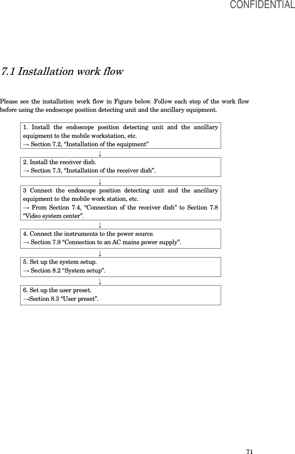
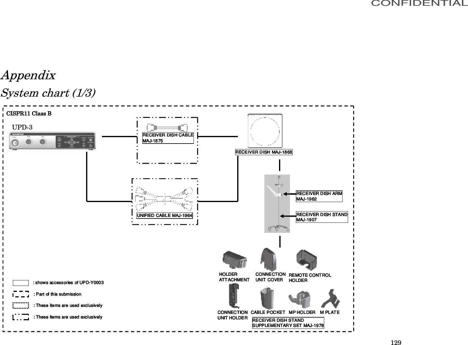
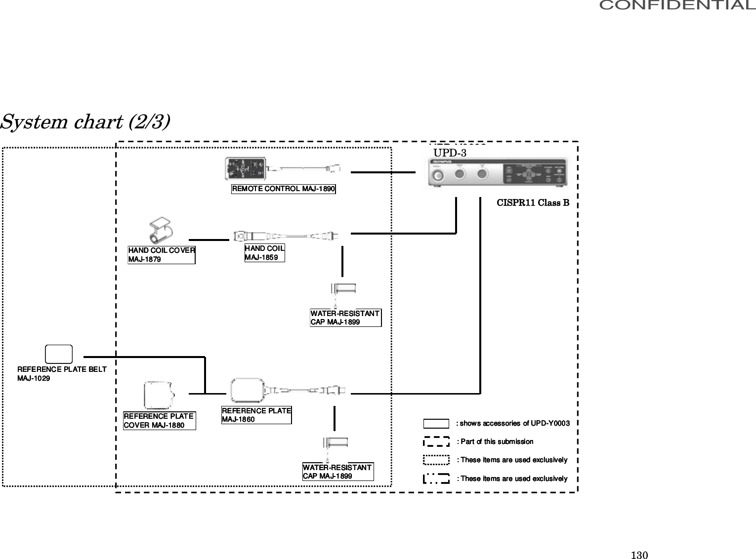
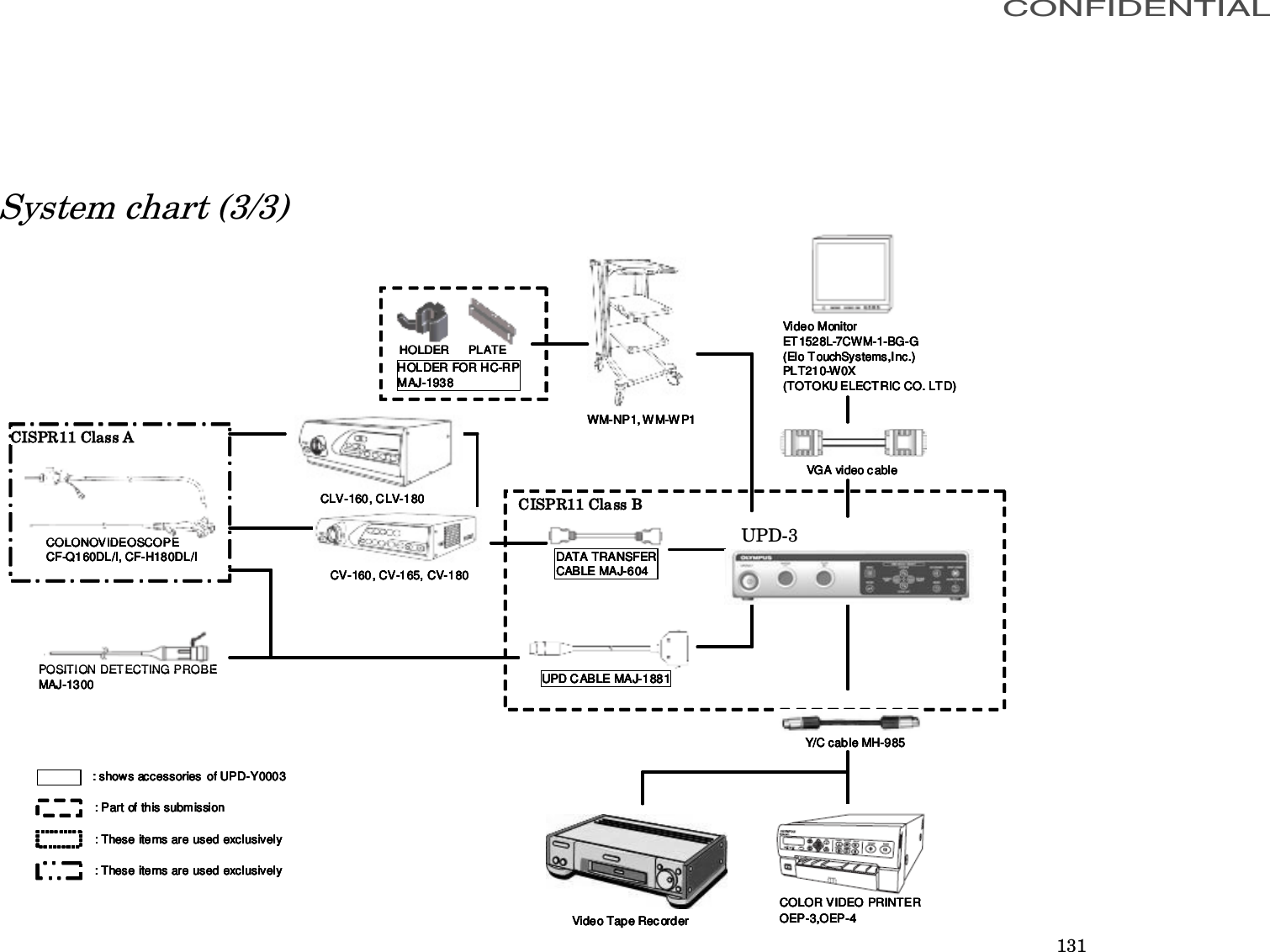
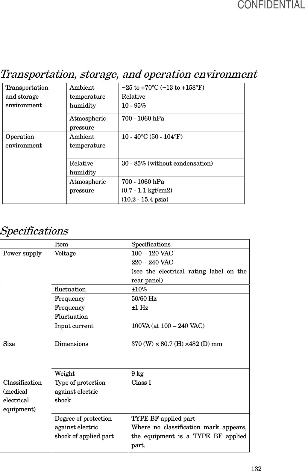
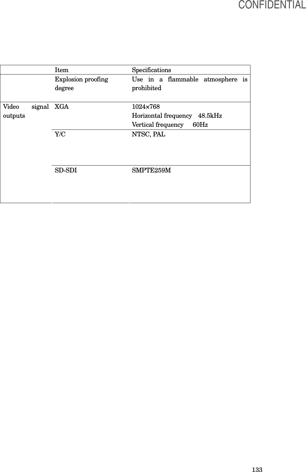
![70 Chapter 7 Installation and Connection [WARNING] • Review this chapter thoroughly, and prepare the instruments properly before use. If the equipment is not properly prepared before each use, equipment damage, patient and operator injury and/or fire can occur. • When non-medical electrical ancillary equipment is used, connect its power cord via an isolation transformer prior to connecting it to this endoscope position detecting unit. [CAUTION] •Turn OFF all instruments before connecting them. Otherwise, equipment damage or malfunction may result. • Use appropriate cables only. Otherwise, equipment damage or malfunction can result. • Properly and securely connect all cables. Otherwise, equipment damage or malfunction can result. • The cables should not be sharply bent, pulled, twisted or crushed. Cable damage can result. • Never apply excessive force to connectors. This could damage the connectors. • Use this instrument only under the conditions described in “Transportation, storage, and operation environment” and “Specifications” in the Appendix. Otherwise, improper performance, compromised safety and/or equipment damage may result. • When moving the receiver dish stand from one location to another, firmly hold the handle with one hand and the pole with the other. Otherwise, the stand may topple, which may result in operator injury or damage of the endoscope position detecting unit. Prepare this endoscope position detecting unit and compatible equipment (shown in the “System chart” in the Appendix) before each use. Referring to the instruction manuals of each system component, install and connect the equipment according to the procedure described in this chapter. CONFIDENTIAL](https://usermanual.wiki/Olympus-Medical-Systems/UPD-3.Instruction-Manual/User-Guide-1366365-Page-70.png)
![72 7.2 Installation of the equipment [WARNING] • Keep the ventilation grills of the endoscope position detecting unit clear. The ventilation grills are located on the side panels. Blockage can cause overheating and equipment damage. • Clean and vacuum dust the ventilation grills using a vacuum cleaner. Otherwise, the endoscope position detecting unit may break down from over heating. • Place the endoscope position detecting unit on a stable, level surface. Otherwise, the endoscope position detecting unit may topple down or drop, and user or patient injury may occur, or equipment damage can result. • If a trolley other than the mobile workstation (WM-NP1 or WM-WP1) is used, confirm that the trolley can withstand the weight of the equipment installed on it. • Do not install the endoscope position detecting unit near a source of strong magnetic wave (microwave treatment device, short wave treatment device, MRI, radio equipment, etc.). Otherwise, the endoscope position detecting unit may malfunction. •Do not fix the cable using surgical clamps, such as Pean, because the cable may break. •Do not allow the cables to catch operator’s legs. Otherwise, the operator and equipment may be toppled. •Connect the cables securely and lock the connectors if they have locks. Otherwise, the equipment may not operate correctly. ○ Installation on the mobile workstation (WM-NP1, WM-WP1) 1. Place the mobile workstation on a level and flat floor. Lock the caster brakes by pushing them down (see Figure). 2. Install the mobile shelf of the mobile workstation according to the configuration of the equipment installed on it as described in the mobile workstation's instruction manual. 3. Place the endoscope position detecting unit on the mobile shelf of the mobile workstation. CONFIDENTIAL](https://usermanual.wiki/Olympus-Medical-Systems/UPD-3.Instruction-Manual/User-Guide-1366365-Page-72.png)
![73 ○ Installation in another location When the equipment is installed in the location other than in the mobile workstation, put it in the level position. 7.3 Installation of the receiver dish ○How to assemble the receiver dish stand [CAUTION] •The weight is very heavy. Be careful not to drop it while assembling the stand. Otherwise, user injury may result. •Assemble the receiver dish stand on a level and flat floor. Otherwise, the receiver dish stand may topple, which may result in user injury or damage of the stand. 1. Insert the end of the pole with a screw hole into the hole of the base (see Figure). The pole is inserted. CONFIDENTIAL](https://usermanual.wiki/Olympus-Medical-Systems/UPD-3.Instruction-Manual/User-Guide-1366365-Page-73.png)
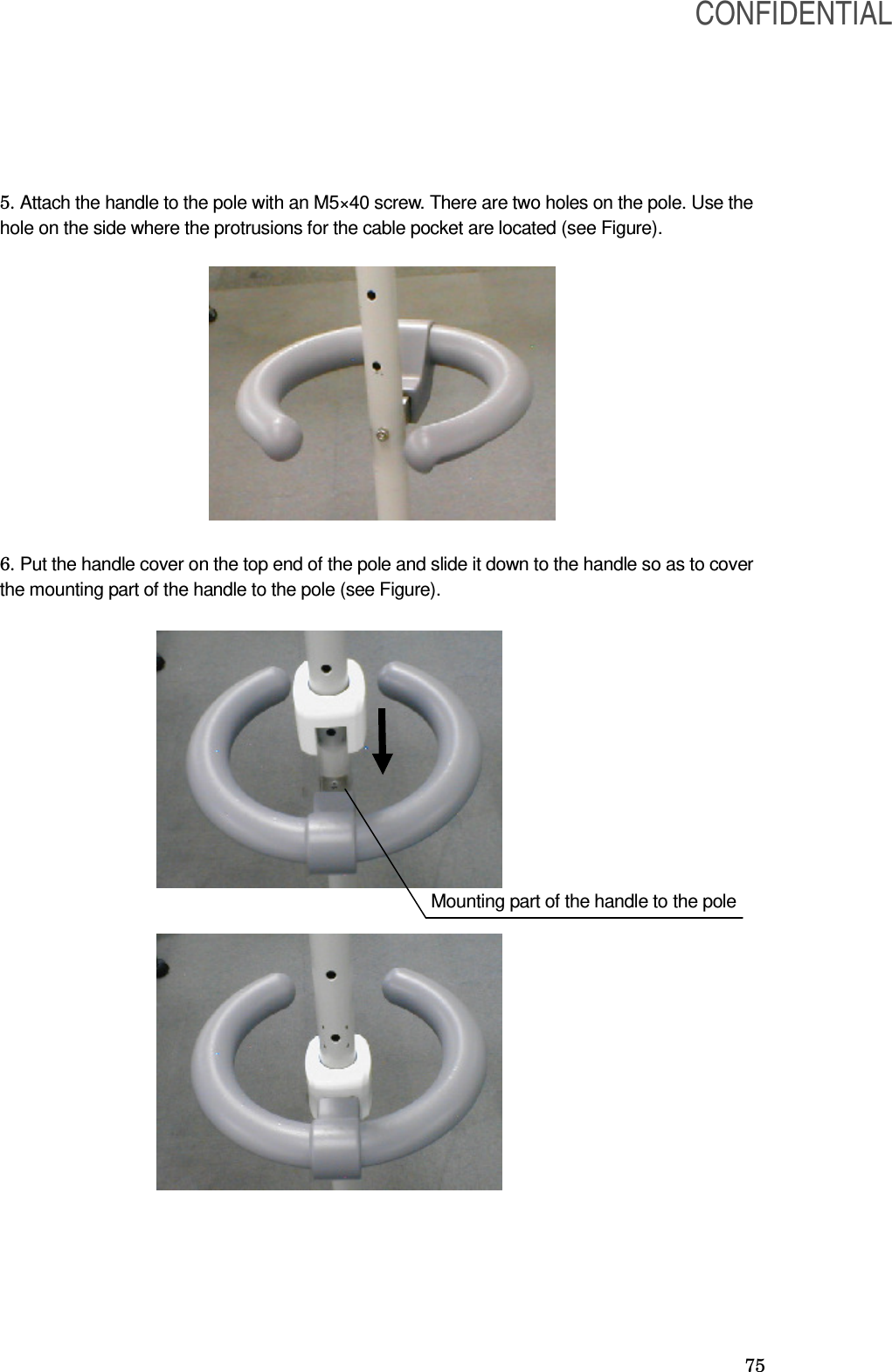
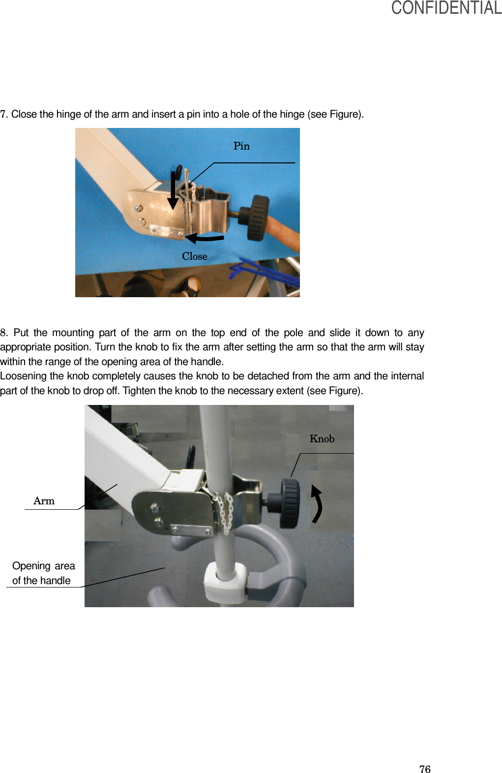
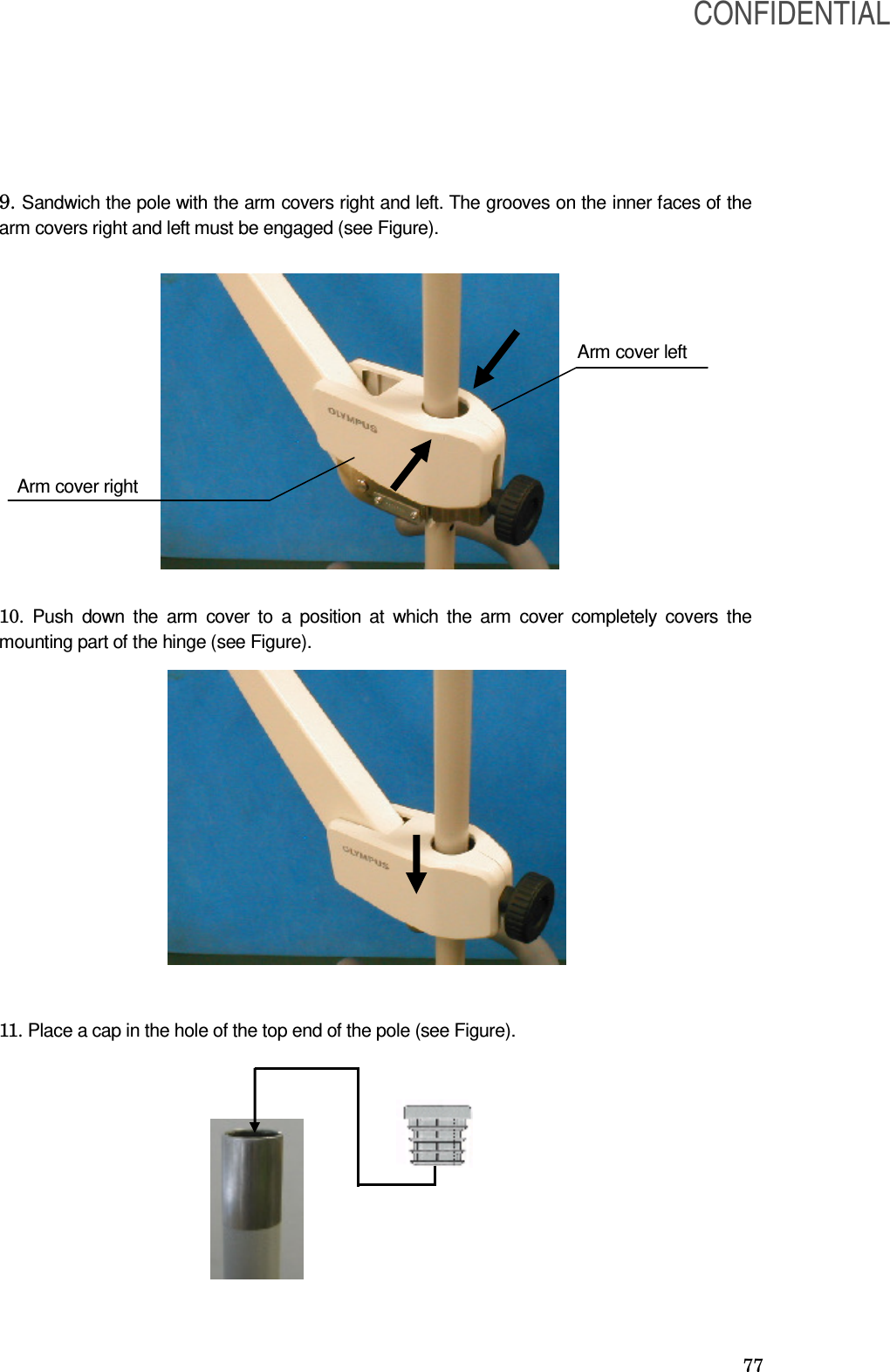
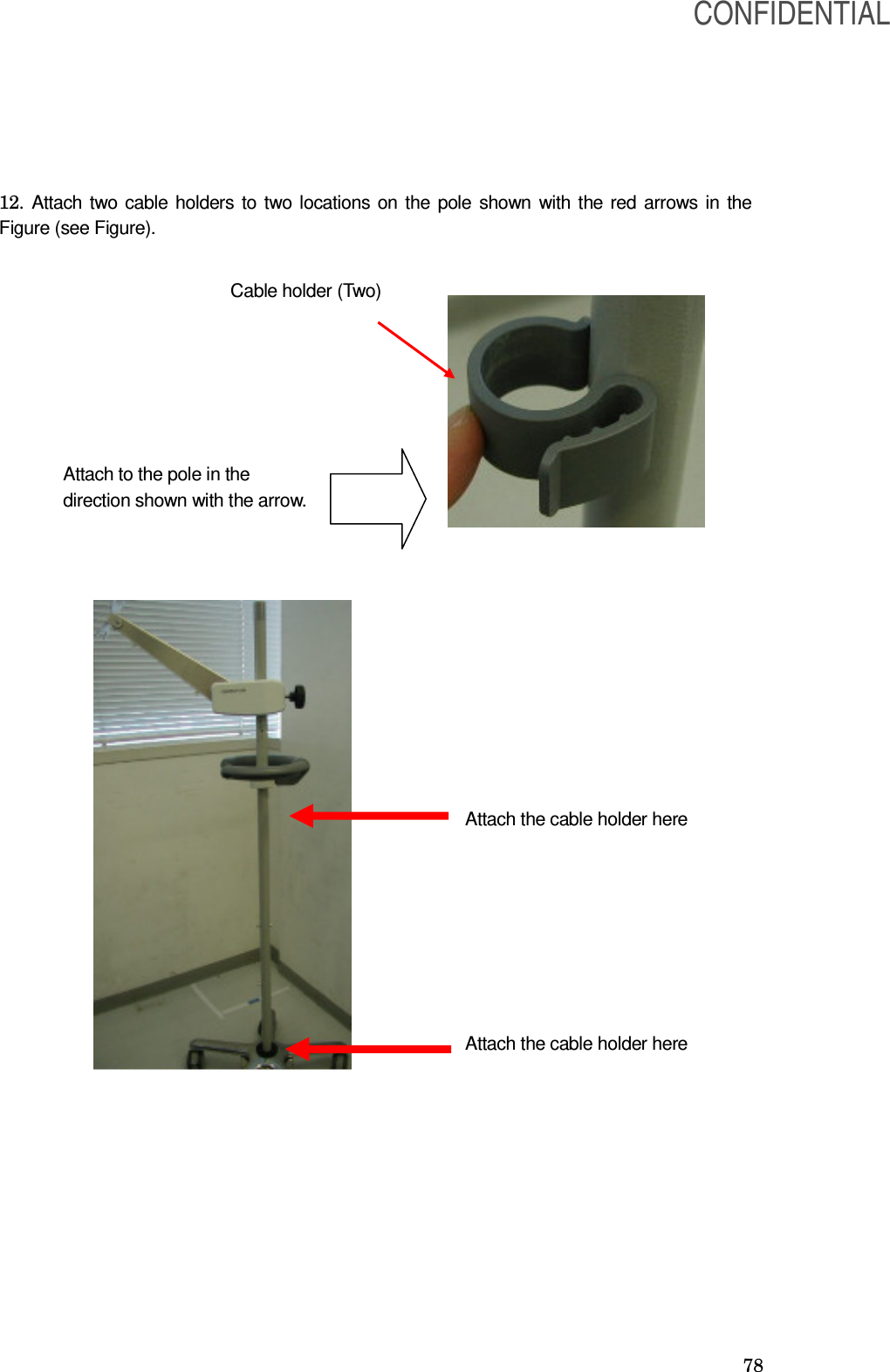
![74 2. Lay down the assembled pole and the base gently on the floor. Attach the weight to the base so that the grooves of the weight fit the base (see Figure) [CAUTION] •Be sure to attach the weight to the base. Otherwise, the stand may topple. 3. Tighten the weight, the base, and the pole together with an M8 x 50screw. The screw must be tightened firmly so that the pole and the base do not wobble (see Figure). 4. Lift up the pole and the base and lock the casters. Two casters have locking mechanism (see Figure). Groove CONFIDENTIAL](https://usermanual.wiki/Olympus-Medical-Systems/UPD-3.Instruction-Manual/User-Guide-1366365-Page-74.png)
![79 ○Installation of the holder for hc-rp and the remote control holder onto the receiver dish stand The holder for hc-rp can hold the hand coil (MAJ-1859) and the reference plate (MAJ-1860).The remote control holder can hold the remote control (NAJ-1890). The holder hc-rp and the remote control holder are included in the receiver dish stand supplementary set (MAJ-1978). [NOTE] The holder for hc-rp and the remote control holder are optional. 1. Install the holder attachment onto the top of the pole (see Figure). If the cap is attached to the top of the pole, remove it before installing the holder for hc-rp. Holder attachment Fix with the screw included in the supplementary set The Holder attachment is installed. CONFIDENTIAL](https://usermanual.wiki/Olympus-Medical-Systems/UPD-3.Instruction-Manual/User-Guide-1366365-Page-79.png)
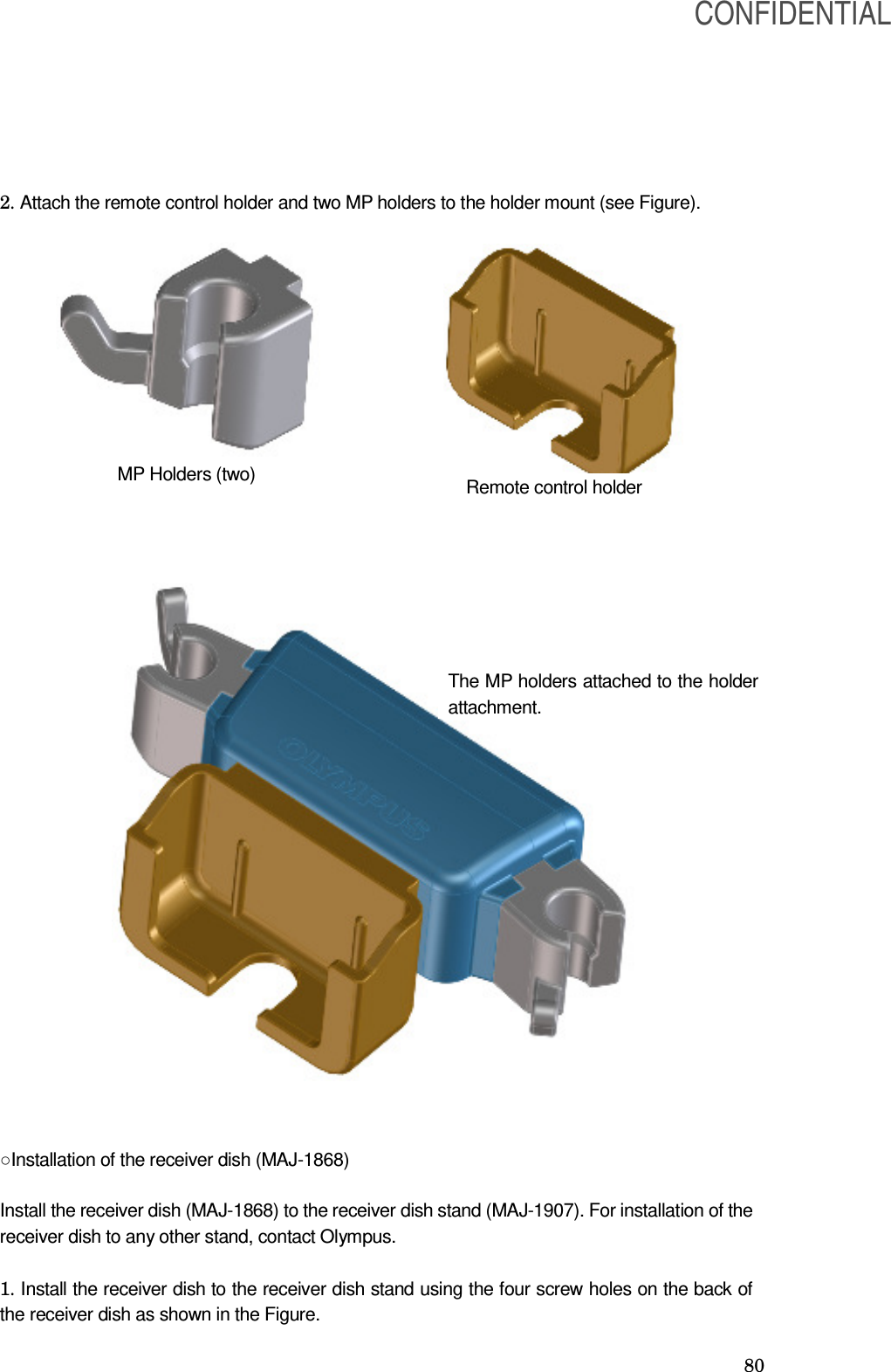
![82 ○ Installation of the holder to the receiver dish The holder can hold the hand coil (MAJ-1859). The holder and the M plate are included in the receiver dish stand supplementary set (MAJ-1978). [NOTE] The holder and the M plate are optional. 1. Remove the two screws out of the four which are fixing the receiver dish (MAJ-1868) as shown in Figure (see Figure). Remove two screws Top Bottom CONFIDENTIAL](https://usermanual.wiki/Olympus-Medical-Systems/UPD-3.Instruction-Manual/User-Guide-1366365-Page-82.png)
![83 2. Install the M plate as shown in the figure. Then attach the holder to the M plate (see Figure). ○Installation of the cable pocket The cable pocket is included in the receiver dish stand supplementary set (MAJ-1978). [NOTE] The cable pocket is optional. The M plate is installed. Tighten the screws again The MP holder is attached MP holder CONFIDENTIAL](https://usermanual.wiki/Olympus-Medical-Systems/UPD-3.Instruction-Manual/User-Guide-1366365-Page-83.png)
![84 1. Attach the cable pocket to the pole of the receiver dish stand so that the two projections on the pole stay in the two holes of the cable pocket. ○Installation of the holder for hc-rp (MAJ-1938) to the mobile workstation The holder for hc-rp can hold the hand coil (MAJ-1859) or the reference plate (MAJ-1860). The holder for hc-rp can be installed to the following mobile workstations WM-P1 and WM-260* series [NOTE] The holder for hc-rp (MAJ-1938) is optional. * This product may not be available in some areas. CONFIDENTIAL](https://usermanual.wiki/Olympus-Medical-Systems/UPD-3.Instruction-Manual/User-Guide-1366365-Page-84.png)
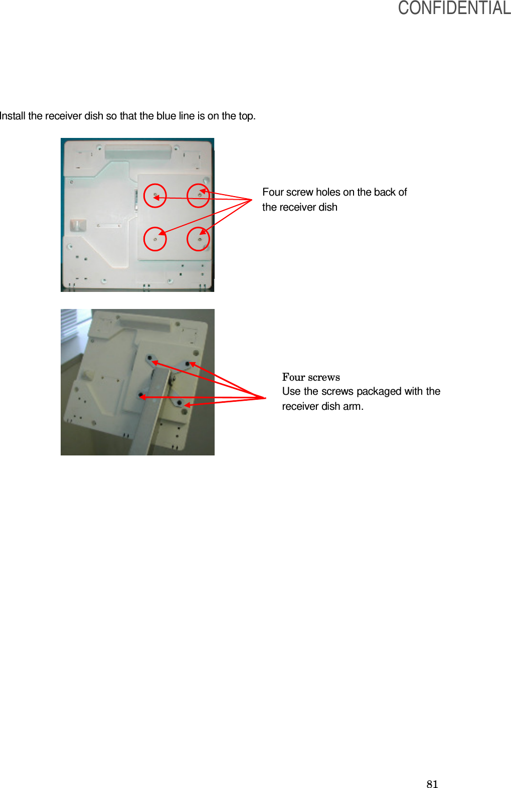
![85 1. Install the plate to the top tray of the mobile workstation. Install the screw, washers and nut in the order shown in Figure. 1. Install two holders onto the plate (see Figure). 7.4 Connection of the receiver dish 1. Check that no video monitor, PC monitor, or a large metallic object is near the receiver dish. Keep a distance of at least 30 cm between the video monitor, PC monitor, or metallic object and the receiver dish. [CAUTION] Screw Wave washer Flat washer Plate Mobile workstation Nut Use these screw holes Plate Top tray Holder Two holders are installed. CONFIDENTIAL](https://usermanual.wiki/Olympus-Medical-Systems/UPD-3.Instruction-Manual/User-Guide-1366365-Page-85.png)
![86 • If a video monitor or PC monitor is located near the coil unit of the endoscope position detecting unit, the scope model display may be distorted or deformed due to strong magnetic fields produced by the monitor. • If a metallic object is located near the coil unit of the endoscope position detecting unit, the scope model display may also be distorted or deformed. • In some cases, the material and/or structure of the operating table may cause distortion or deformation of the scope model display. [NOTE] If you have any questions or problems with the installation location of the endoscope positioning detecting unit or the material and/or structure of the operating table in use, contact Olympus. 2. For connecting the receiver dish to the endoscope position detecting unit, use the cable listed below. Model Product name Note MAJ-1875 Receiver dish cable 7m RECEIVER DISH UPD-3 MAJ-1868 Connector MAJ-1875 7.5 Video equipment [NOTE] See the instruction manual for the video equipment to be used. CONFIDENTIAL](https://usermanual.wiki/Olympus-Medical-Systems/UPD-3.Instruction-Manual/User-Guide-1366365-Page-86.png)
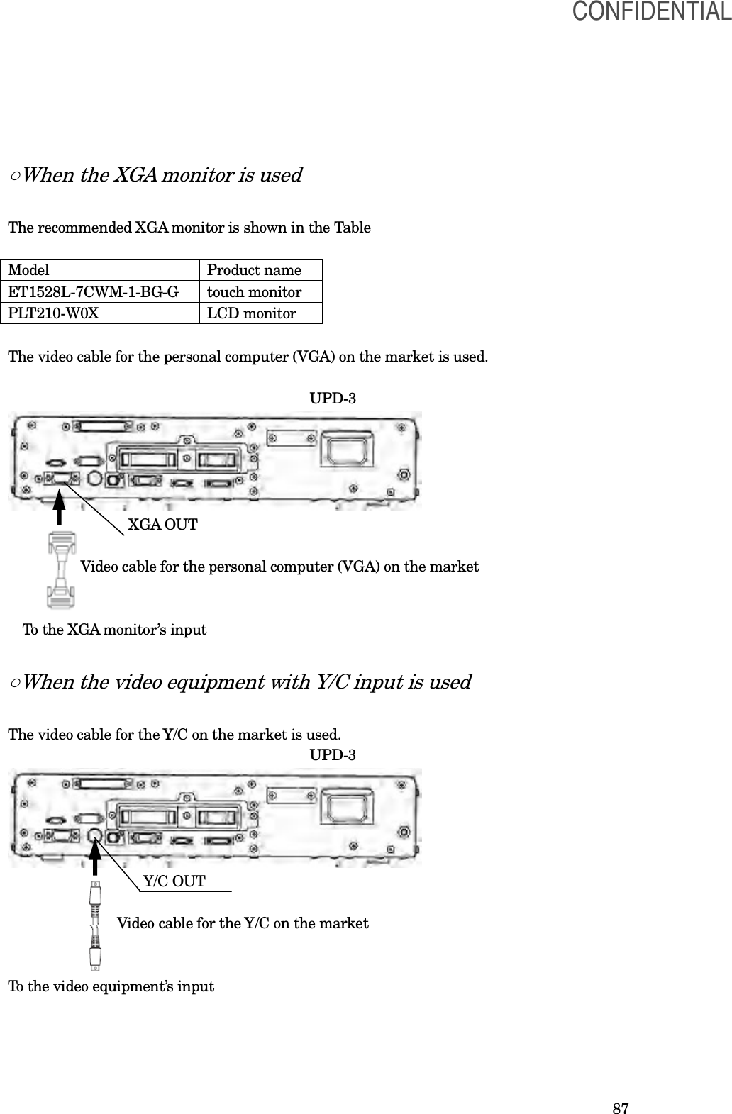
![88 ○When the video equipment with SDI input is used For connecting the SDI video equipment to the endoscope position detecting unit, use the cable listed below. Table Model Product name Note MAJ-1464 SDI cable 22m UPD-3 MAJ-1464 SDI OUT To the video equipment’s input 7.6 UPD cable [WARNING] Do not place the UPD cable on the operating table. This could result in an infection when the patient contacts the UPD cable. Also, the scope model display may become distorted or deformed. [CAUTION] • Always turn the endoscope position detecting unit OFF before connecting or disconnecting the UPD cable. Otherwise, equipment damage or malfunction may result. • Do not apply excessive force to the UPD cable; it may cause equipment damage. • Do not immerse the UPD cable in liquids or allow it to become wet; it may cause equipment damage or malfunction. • Do not touch the electrical contacts inside the endoscope position detecting unit’s connectors; it may cause equipment damage or malfunction. Use the cable shown in Table Table Model Product name Note MAJ-1881 UPD cable CONFIDENTIAL](https://usermanual.wiki/Olympus-Medical-Systems/UPD-3.Instruction-Manual/User-Guide-1366365-Page-88.png)
![89 7.7 Remote control [WARNING] •Install the remote control on a stable, level surface so that the cable between the endoscope position detecting unit and remote control is not stretched. Otherwise, the remote control may slip or fall and result in patient/operator injury or damage to the equipment. The following remote control shown in Table is available. Table Model Product name Note MAJ-1890 Remote control REMOTE CONTROL UPD-3 MAJ-1890 7.8 Video system center [NOTE] See the instruction manual for the video system center. When connecting the video system center to the position detecting unit, the following patient data displayed on the video system center can be output to the position detecting unit. • ID number • Patient’s name • Sex and Age • Date of birth CONFIDENTIAL](https://usermanual.wiki/Olympus-Medical-Systems/UPD-3.Instruction-Manual/User-Guide-1366365-Page-89.png)
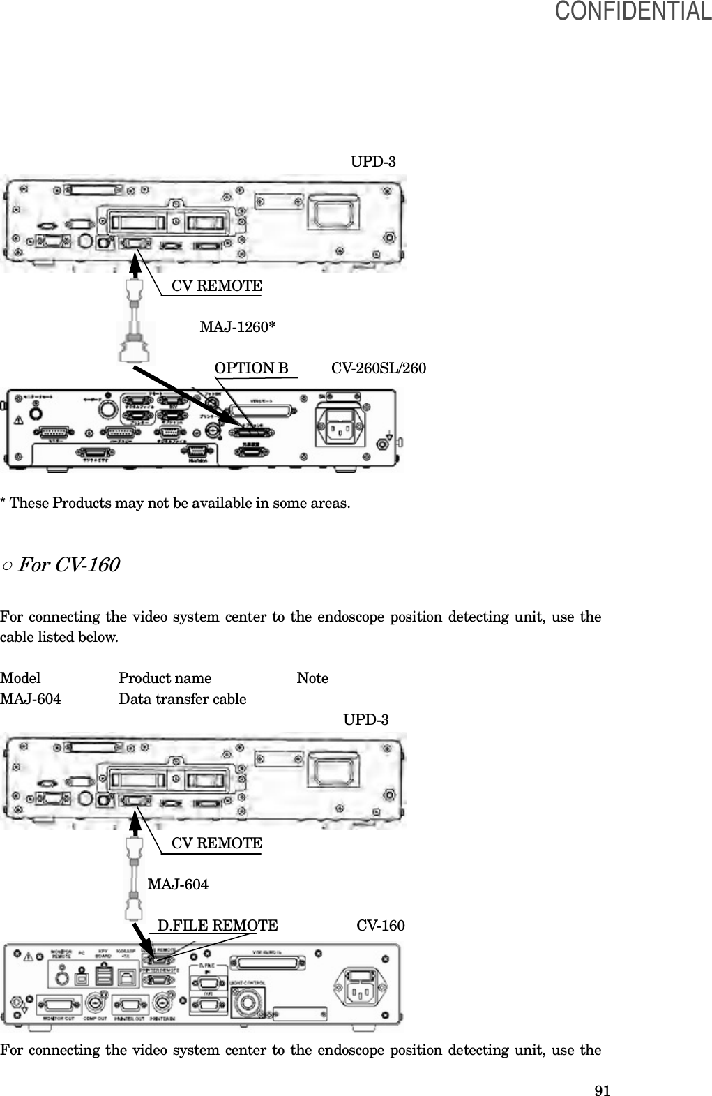
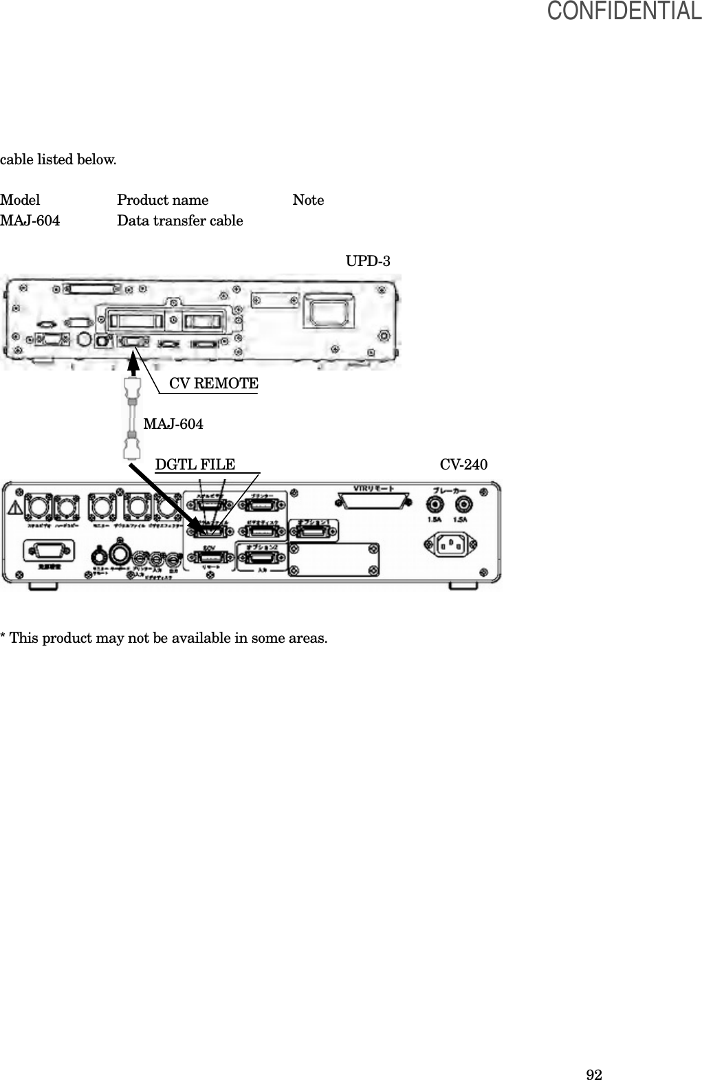
![90 ○ For CV-180 [CAUTION] When displaying the image of the position detecting unit (UPD-3) using the PinP function of the CV-180, use the high definition LCD monitor. Otherwise, the scope model may not be displayed clearly For connecting the video system center to the endoscope position detecting unit, use the cable listed below. Table Model Product name Note MAJ-604 Data transfer cable UPD-3 CV REMOTE MAJ-604 PC REMOTE CV-180 ○ For CV-260SL/260 * For connecting the video system center to the endoscope position detecting unit, use the cable listed below. Model Product name Note MAJ-1260* Data transfer cable CONFIDENTIAL](https://usermanual.wiki/Olympus-Medical-Systems/UPD-3.Instruction-Manual/User-Guide-1366365-Page-90.png)
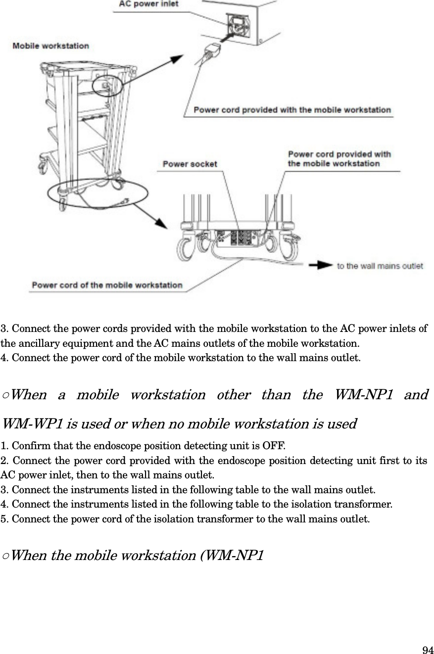
![93 7.9 Connection to an AC mains power supply [DANGER] • Be sure to connect the power plug of the power cord directly to a grounded wall mains outlet. If the endoscope position detecting unit is not grounded properly, it can cause an electric shock and/or fire. • Do not connect the power plug to the 2-pole power circuit with a 3-pole to 2-pole adapter. It can prevent proper grounding and cause an electric shock. [WARNING] • Always keep the power plug dry. A wet power plug may cause electric shocks. • Confirm that the hospital-grade wall mains outlet to which this instrument is connected has adequate electrical capacity that is larger than the total power consumption of all connected equipment. If the capacity is insufficient, fire can result or circuit breaker may trip and turn OFF this instrument and all other equipment connected to the same power circuit. • When using the mobile workstation (WM-NP1, WM-WP1), confirm that the mobile workstation has adequate electrical capacity that is larger than the total power consumption of all connected equipment. If the capacity is insufficient, drop in the supply voltage can result or the electric protective device may trip and turn OFF all the equipment connected to the mobile workstation. • When non-medical ancillary electrical equipment is used, always connect the equipment to a wall mains outlet via an isolation transformer. Otherwise, electric shock can result. • The total power consumption of all connected equipment to the isolation transformer should not exceed the rating of the isolation transformer. If it exceeds, add another isolation transformer. Otherwise, the equipment may not work correctly. • Do not bend, pull or twist the power cord. Equipment damage including separation of the power plug and disconnection of the cord wire as well as fire or electric shock can result. • Be sure to connect the power plug securely to prevent erroneous unplugging during use. Otherwise, the equipment will not function. • Do not extend a single wall mains outlet into multiple outlets for connecting the power cords of both the electrosurgical unit and light source. Otherwise, malfunction of the equipment may result. ○When the mobile workstation (WM-NP1, WM-WP1) is used 1. Confirm that the endoscope position detecting unit is OFF. 2. Connect the power cord provided with the mobile workstation to the AC power inlet of the endoscope position detecting unit and the AC mains outlet of the mobile workstation (see Figure) CONFIDENTIAL](https://usermanual.wiki/Olympus-Medical-Systems/UPD-3.Instruction-Manual/User-Guide-1366365-Page-93.png)
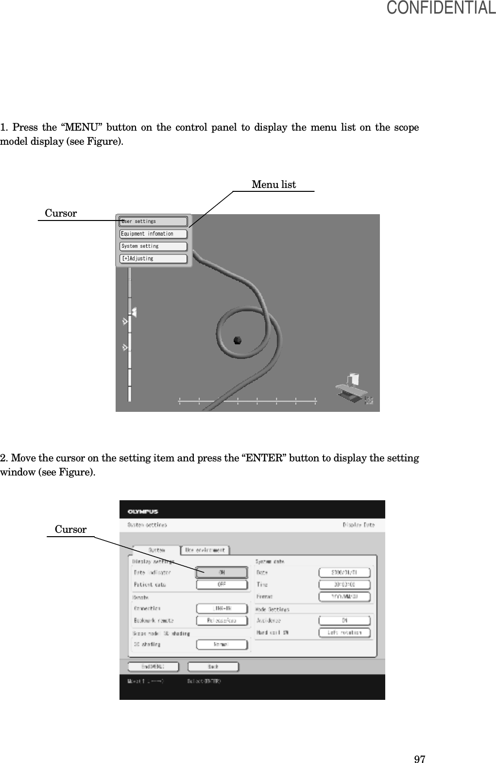
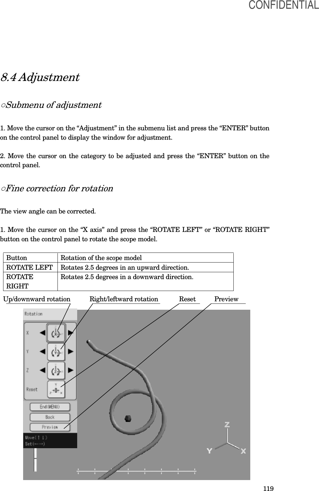
![96 Chapter 8 Function setup The following settings are set to use the position detecting unit and equipment connected to the position detecting unit properly. Setting menu Description System setup Sets the basic functions of the position detecting unit. For details on the functions, refer to “system setup”. User preset Sets the functions used during the examination. For details on the functions, refer to “User preset”. Adjustment Adjusts the scope display. For details, refer to “ ” . [NOTE] The functions can be set even if the endoscope or the position detecting probe is not connected to the position detecting unit. 8.1 Basic operation of the menu Buttons in the menu For the buttons and their functions, see Table below. Button Function ROTATE LEFT Moves the cursor to the left. ROTATE RIGHT Moves the cursor to the right. ZOOM IN Moves the cursor up. ZOOM OUT Moves the cursor down. ENTER Determines the category selected by the cursor. MENU Displays or closes the window. ROTATE MENU ZOOM IN RIGHT ENTER ROTATE ZOOM OUT LEFT CONFIDENTIAL](https://usermanual.wiki/Olympus-Medical-Systems/UPD-3.Instruction-Manual/User-Guide-1366365-Page-96.png)
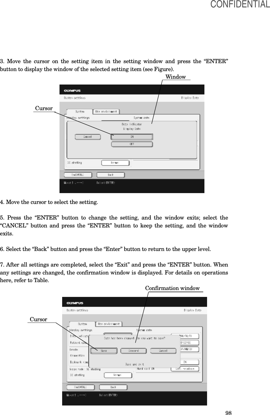
![99 Selection Description Yes Changes settings and exits from the menu. No Not change settings and exits from the menu. Cancel Returns the menu window to continue to change the settings. 8.2 System setup Set various settings, such as the display setting and system date. Settings of the display ○Date and time display 1. Set the display of date and time in the scope model display. Setting value Description ON Displays the current date and time in the scope model display. OFF Not display the current date and time in the scope model display. ○Patient data display 1. Set the display of patient data in the scope model display. Setting value Description ON Displays the patient data in the scope model display. OFF Not display the patient data in the scope model display. [NOTE] The patient data is displayed when the video system center is connected to the position detecting unit. Settings of the miscellanea ○Frequency of transmitting CONFIDENTIAL](https://usermanual.wiki/Olympus-Medical-Systems/UPD-3.Instruction-Manual/User-Guide-1366365-Page-99.png)
![100 1. Set the frequency for detecting the scope model. Setting value Description Automatic Automatically selects the frequency for detecting the scope model from “f1” to “f4”. f1 Use the frequency set in the "f1”. f2 Use the frequency set in the "f2”. f3 Use the frequency set in the "f3”. f4 Use the frequency set in the "f4”. [CAUTION] Do not change this setting in ordinary cases. Otherwise, the scope model display may be distorted or deformed. ○Fusion avoidance function 1. Set the fusion avoidance function. Setting value Description ON Activate the fusion avoidance function. OFF Inactivate the fusion avoidance function. [CAUTION] Do not change this setting in ordinary cases. Otherwise, the scope model display may be distorted or deformed. ○Marking remote This function is the future extension; it is not used currently. ○Model shading 1. Enhance the contrast of the shading of the scope model Setting value Description Standard No enhancement is made to the shading contrast of the scope model Enhancement Enhances the shading contrast of the scope model CONFIDENTIAL](https://usermanual.wiki/Olympus-Medical-Systems/UPD-3.Instruction-Manual/User-Guide-1366365-Page-100.png)
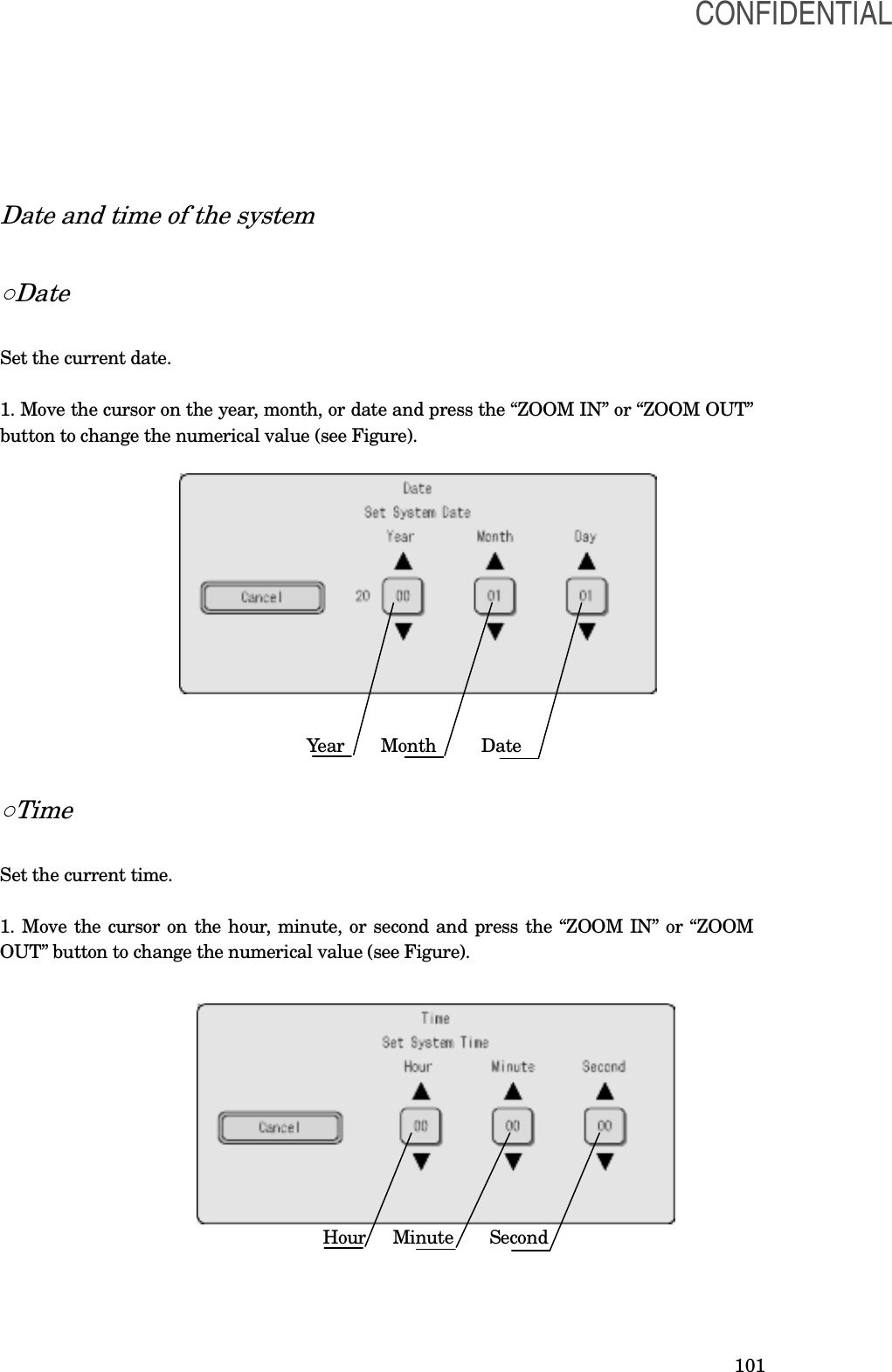
![102 ○Display format 1. Set the date display format. Date display format Description • MM/DD/YYYY • MM-DD-YYYY • MM.DD.YYYY • MM DD YYYY • DD/MM/YYYY • DD-MM-YYYY • DD.MM.YYYY • DD MM YYYY • YYYY/MM/DD • YYYY-MM-DD • YYYY.MM.DD • YYYY MM DD YYYY:Year MM:Month DD:Date ○Hand coil switch 1. Set the functions to be assigned to the remote switch of the hand coil. Setting value Description Scope position Sets the scope position ROTATE LEFT Rotates the scope model in the left direction Split screen Changes the screen between the split-screen and the single-screen ○Display speed 1. Set the display speed of the scope model. Setting value Description Automatic Displays the scope model at high or medium speed depending on the external noise of this instrument Low Displays the scope model at low speed Medium Displays the scope model at medium speed High Displays the scope model at high speed [CAUTION] Do not change this setting in ordinary cases. Otherwise, the scope model display may be unstable. [NOTE] - When the Automatic is selected, the Medium speed mode to display the scope model is CONFIDENTIAL](https://usermanual.wiki/Olympus-Medical-Systems/UPD-3.Instruction-Manual/User-Guide-1366365-Page-102.png)
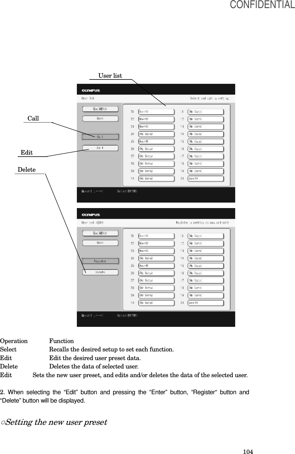
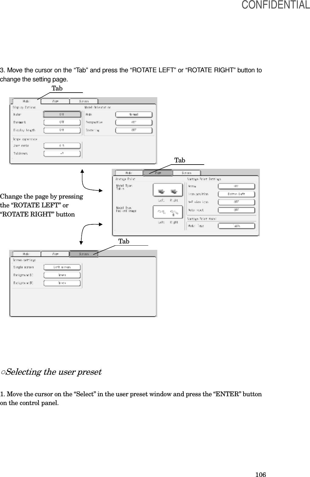
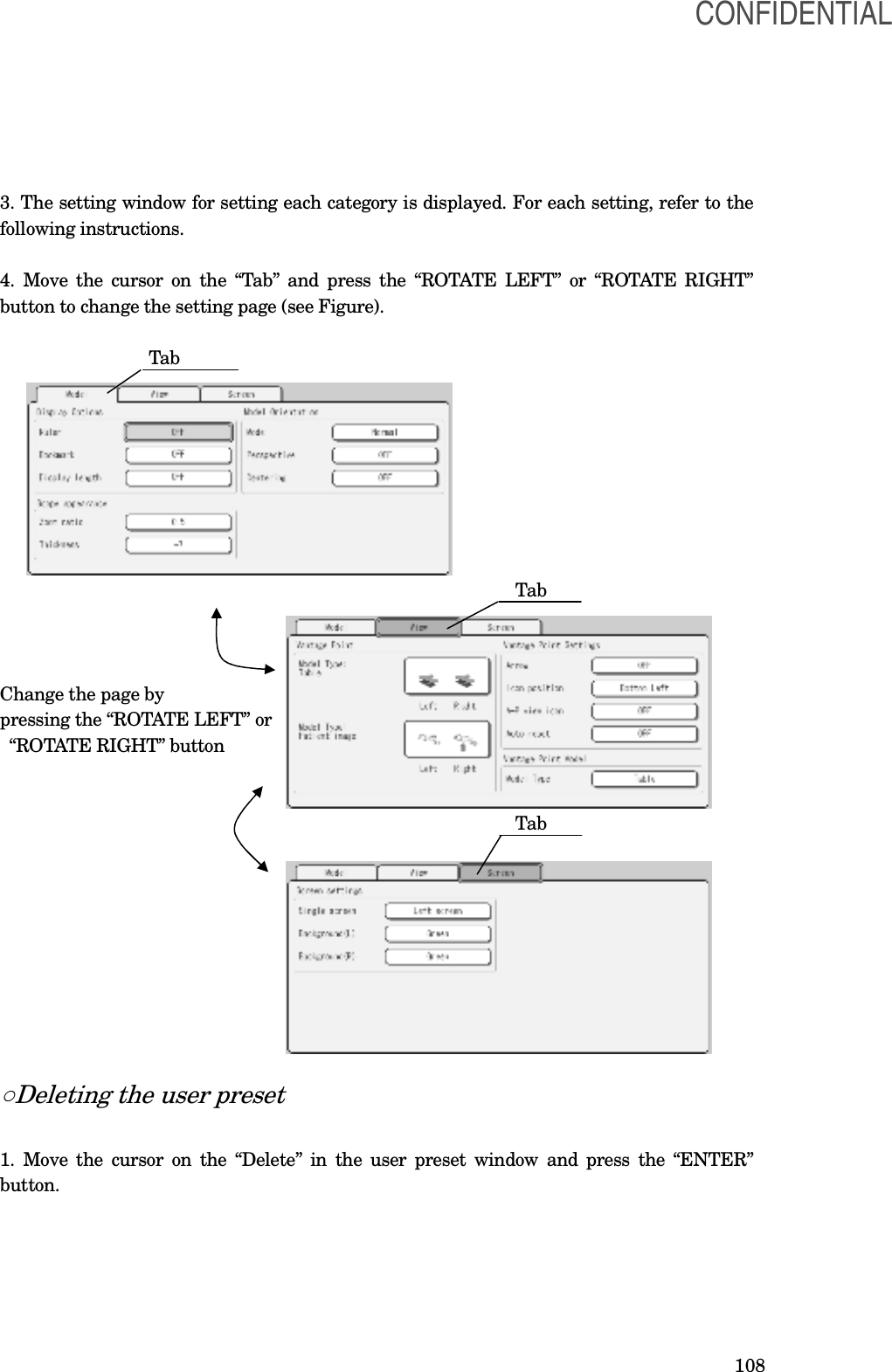
![105 1. Move the cursor on the “New” in the User preset window and press the “ENTER” button on the control panel. 2. The setting window for setting each category is displayed (see Figure). For each setting, refer to the following instructions. Cursor [NOTE] •Each preset data is saved in the user list in order (from No.1 to No.20). The number is suffixed on each user’s name. •When the user list is full, a new preset data cannot be saved. Delete the unnecessary data to save the new data. CONFIDENTIAL](https://usermanual.wiki/Olympus-Medical-Systems/UPD-3.Instruction-Manual/User-Guide-1366365-Page-105.png)
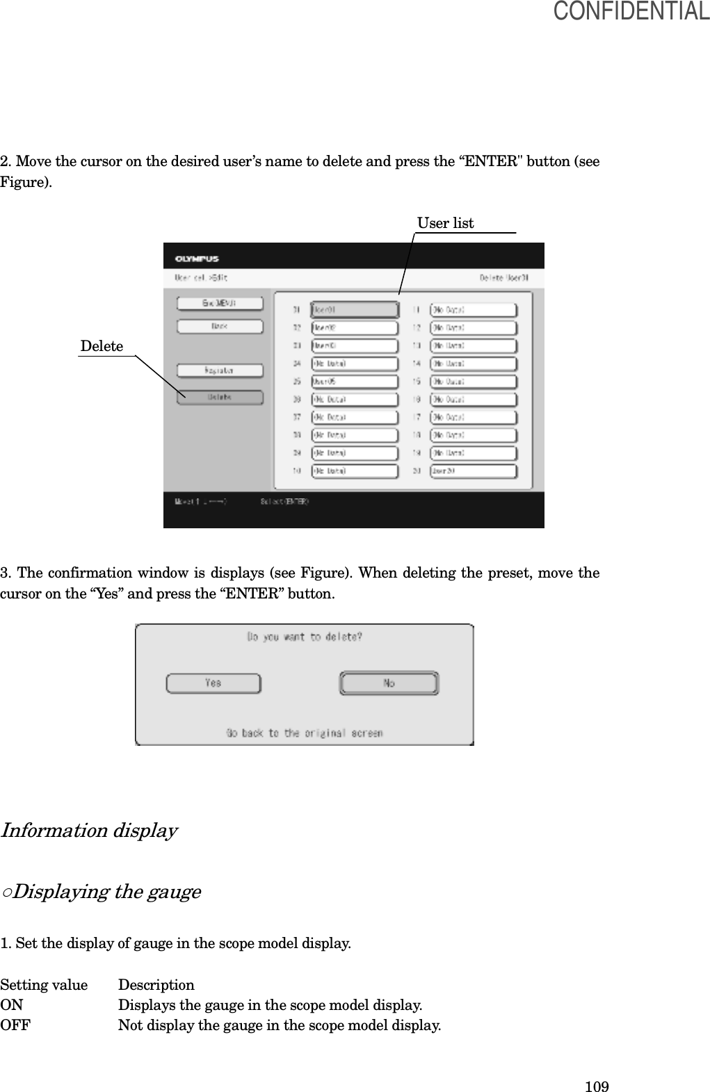
![107 2. Move the cursor on a desired user’s name to recall and press the “ENTER” button on the control panel (see Figure). User list Cursor Select 3. The selected preset is called, and the scope model display is returned. [NOTE] The list of the user preset currently called is displayed in violet. ○Editing the user preset 1. Move the cursor on the “Edit” in the user preset window and press the “ENTER” button. 2. Move the cursor on the desired user’s name to edit and press the “ENTER" button (see Figure). User list Cursor Edit CONFIDENTIAL](https://usermanual.wiki/Olympus-Medical-Systems/UPD-3.Instruction-Manual/User-Guide-1366365-Page-107.png)
![110 ○Displaying the marking 1. Set the display of marking in the scope model display. Setting value Description ON Displays the marking in the scope model display. OFF Not display the marking in the scope model display. ○Displaying the display length 1. Set the display of the display length in the scope model display Setting Value Description ON Displays the display length in the scope model display. OFF Not display the display length in the scope model display. Scope model ○Zooming ratio 1. Set the zooming ratio of the scope model. The ratio can be changed from 0.5 to 3.0 times in steps of 0.1 times. [NOTE] • For zooming in or out the scope model, refer to Section 5.2, “Varying the size of the scope model”. • Pressing the “Reset” button or selecting the desired user preset recalls the zooming ratio that has been saved in the user preset operation. ○Scope model thickness 1. Adjust the scope model thickness from -7 to +7. Display mode CONFIDENTIAL](https://usermanual.wiki/Olympus-Medical-Systems/UPD-3.Instruction-Manual/User-Guide-1366365-Page-110.png)
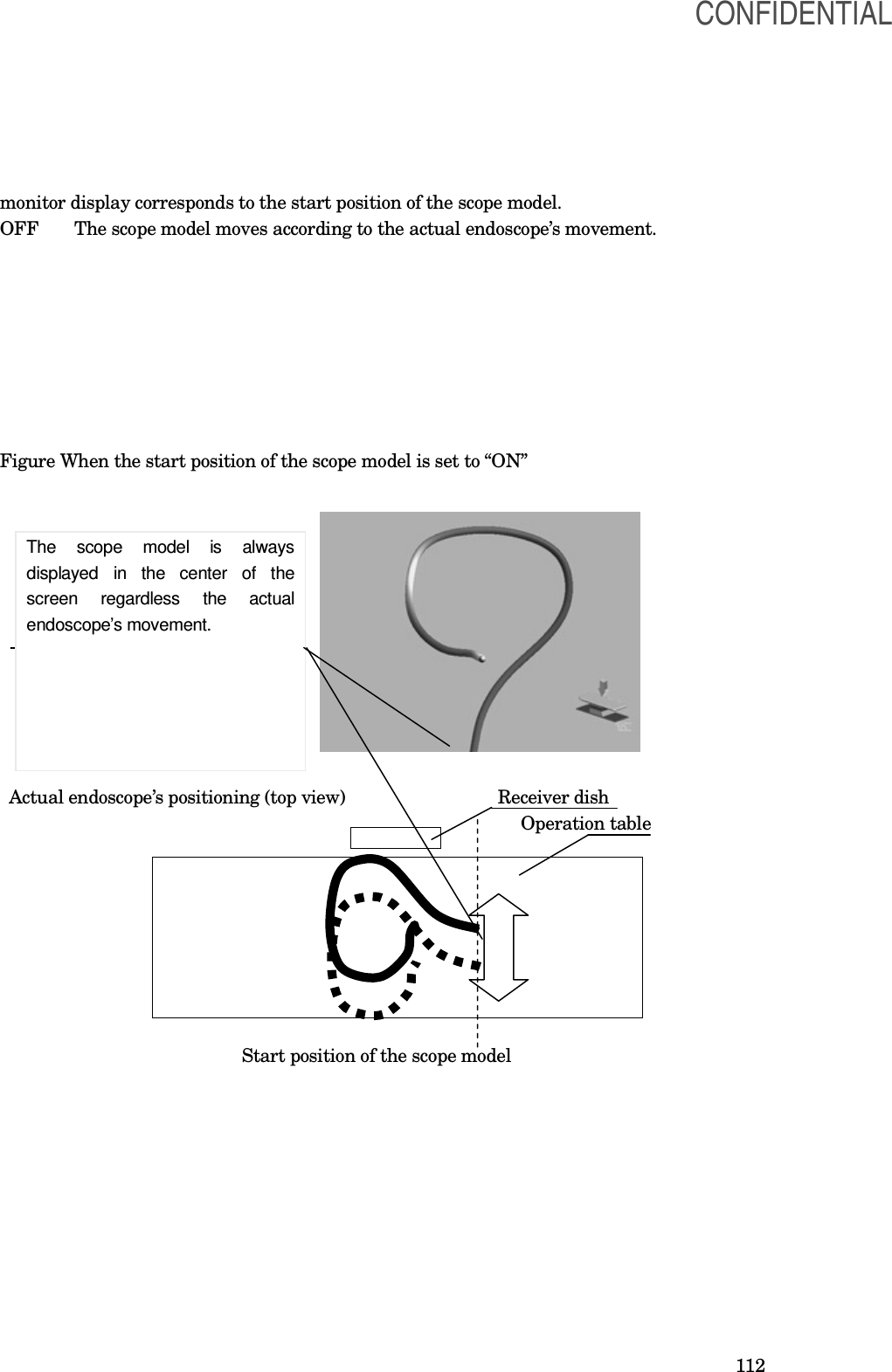
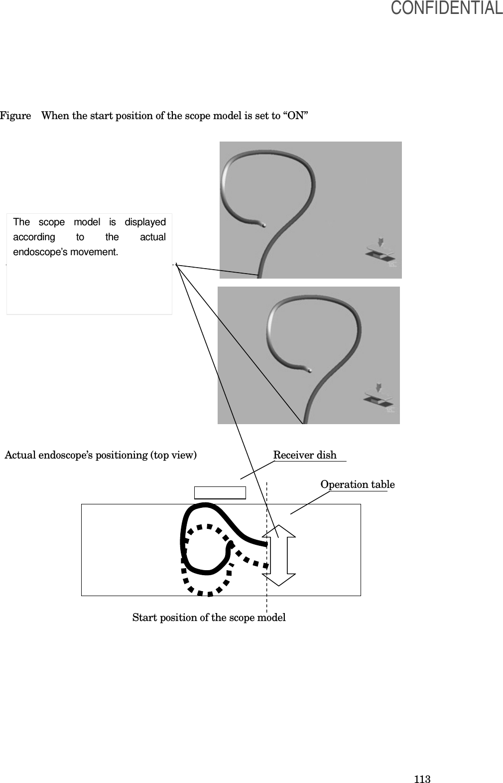
![111 ○Changing the display mode 1. Set the viewing direction of the scope model. Setting value Description From the top Displays the scope model from the top to the bottom in the screen. From the bottom Displays the scope model from the bottom to the top in the screen. [NOTE] For displaying the scope model and its actual position, refer to the Section 4.2, “Scope model display range”. ○Changing the perspective 1. Set the perspective of the scope model. Setting value Description ON The perspective of the scope model is enabled. OFF The perspective of the scope model is disabled. Perspective OFF Perspective ON ○Start position of the scope model 1. Set the start position of the scope model. Setting value Description ON The center of the bottom of the monitor display corresponds to the start position of the scope model. When the display mode is set to “From the top”, the center of the top of the CONFIDENTIAL](https://usermanual.wiki/Olympus-Medical-Systems/UPD-3.Instruction-Manual/User-Guide-1366365-Page-111.png)
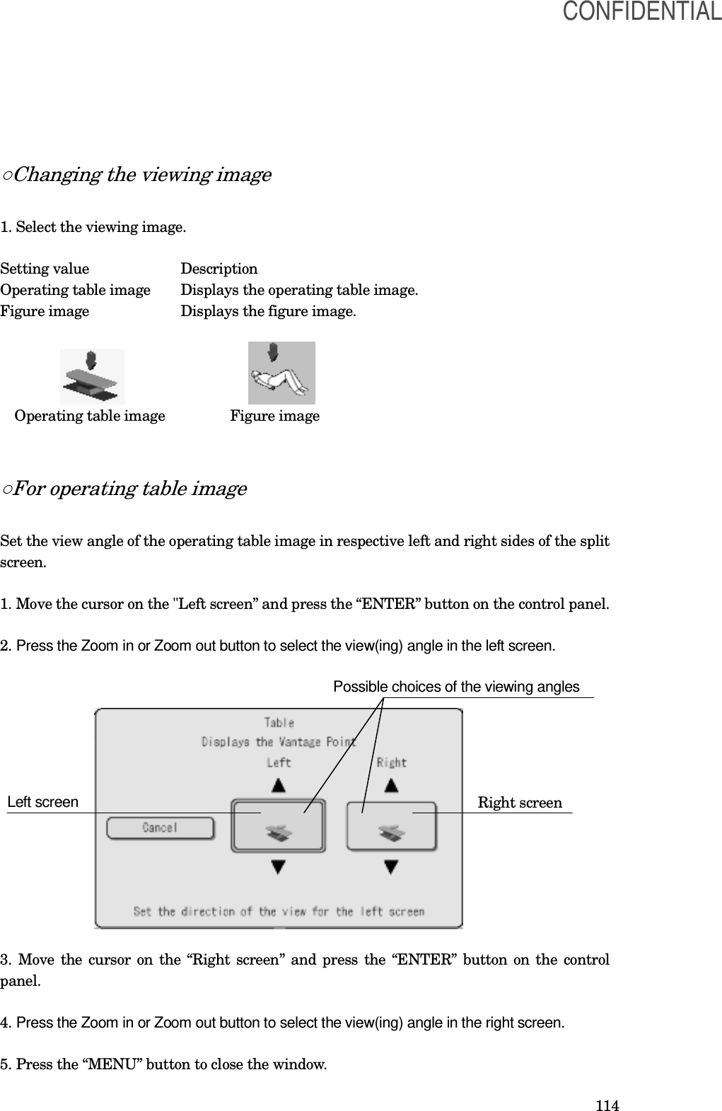
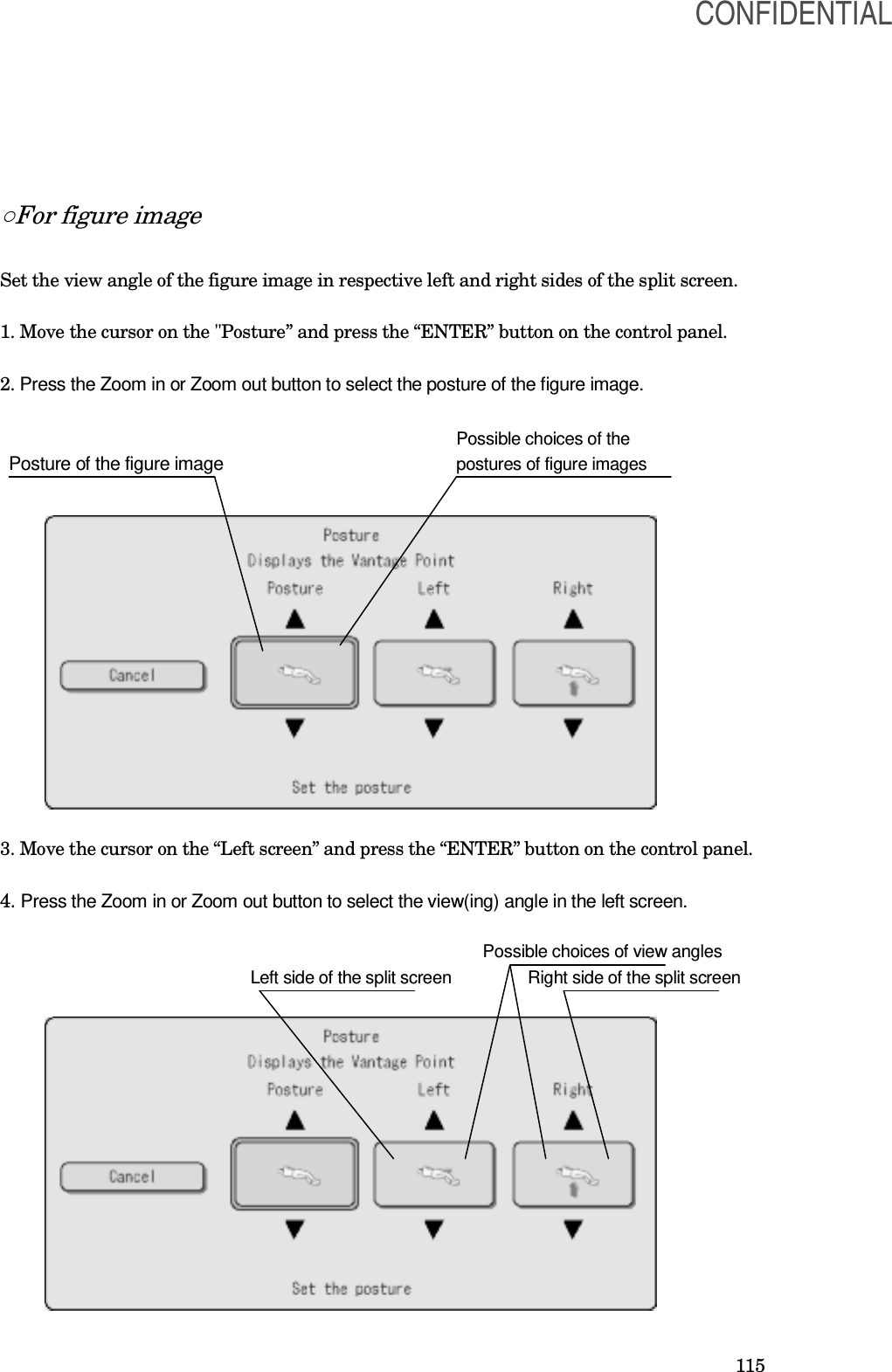
![116 5. Move the cursor on the “Right screen” and press the “ENTER” button on the control panel. 6. Press the Zoom in or Zoom out button to select the view(ing) angle in the right screen. [NOTE] • The view angle against the figure image can be selected from four angles: anterior, posterior, right lateral, or left lateral. Other angles cannot be selected. • The view angle in the left side of the split screen can be selected as either anterior or posterior. The view angle in the right side of the split screen can be selected as either right lateral or left lateral. • The view angle in the single screen is the same as selected for the front/back view or lateral view. Other angles cannot be selected. ○Displaying the viewpoint indicator arrow 1. Set the display of the viewpoint indicator arrow for the figure image. Setting value Description ON Displays the viewpoint indicator arrow for the figure image. OFF Not display the viewpoint indicator arrow for the figure image. ○Displaying position of the figure image 1. Set the displaying position of the figure image Setting value Description Lower left Displays the figure image at the lower left part of the screen. Upper right Displays the figure image at the upper right part of the screen. ○Displaying the AP symbol 1. Set the display of the AP icon in the left screen in the split-screen display mode. Setting value Description ON Displays the AP symbol in the left screen. OFF Not display the AP symbol in the left screen. CONFIDENTIAL](https://usermanual.wiki/Olympus-Medical-Systems/UPD-3.Instruction-Manual/User-Guide-1366365-Page-116.png)
![117 ○Automatic resetting of the posture of the figure image 1. Set automatic resetting of the viewing angle and the posture of the figure image at completion of the examination. Setting value Description ON Resets the viewing angle automatically at completion of the examination. OFF Not reset the viewing angle automatically at completion of the examination. [NOTE] For the method to change the viewing angle, see Section 5.1 “Rotating the scope model”. ○Single screen 1. Set the view angle in the single screen. Setting value View angle in the single screen Left side The view angle in the left side of the split screen. Right side The view angle in the right side of the split screen. ○Setting the background color in right and left sides of the split screen 1. The background color of the respective right and left sides of the split screens can be selected. Setting value Black Green Blue CONFIDENTIAL](https://usermanual.wiki/Olympus-Medical-Systems/UPD-3.Instruction-Manual/User-Guide-1366365-Page-117.png)
![118 Bluish violet gradation ○Resetting 1. Select whether the view angle is reset automatically at the end of the examination. Setting value Description ON Resets the view angle automatically at the end of the examination. OFF Not reset the view angle automatically at the end of the examination. [NOTE] For changing the view angle, refer to Section 5.1, “Rotating the scope model”. ○Displaying the viewpoint indicator arrow 1. Select whether the viewpoint indicator arrow for the figure image is displayed. Setting value Description ON Displays the viewpoint indicator arrow for the figure image. OFF Not display the viewpoint indicator arrow for the figure image. CONFIDENTIAL](https://usermanual.wiki/Olympus-Medical-Systems/UPD-3.Instruction-Manual/User-Guide-1366365-Page-118.png)
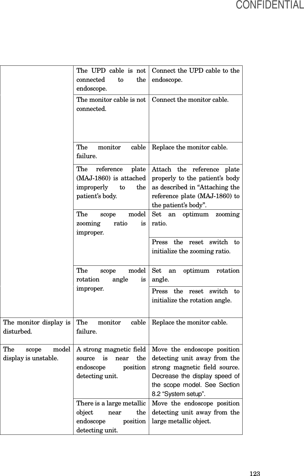
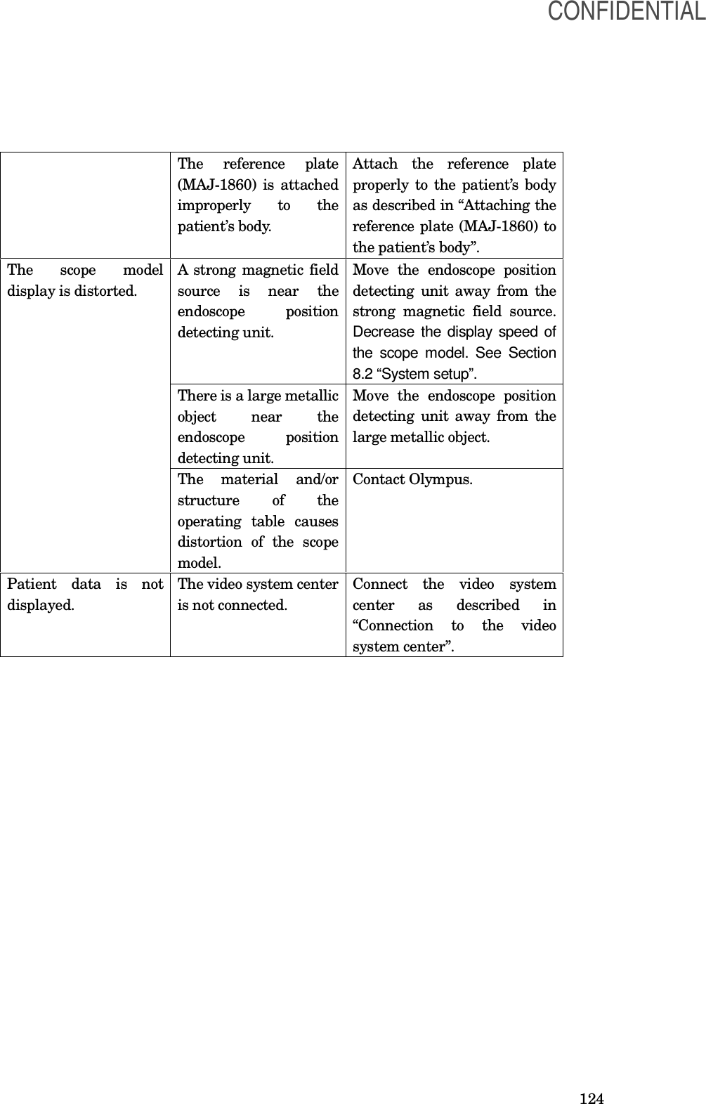
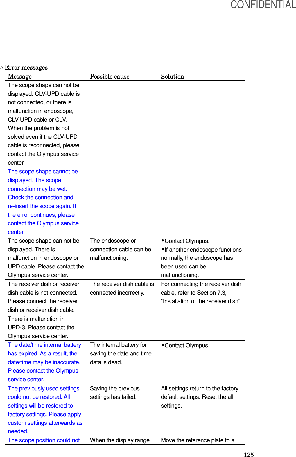
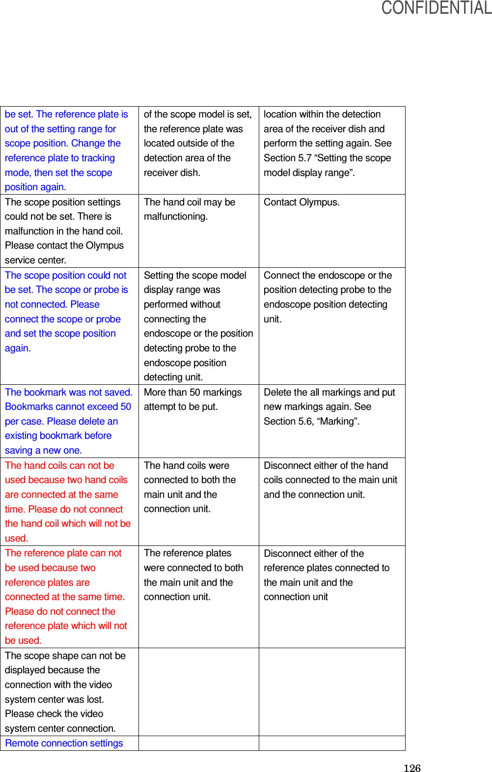
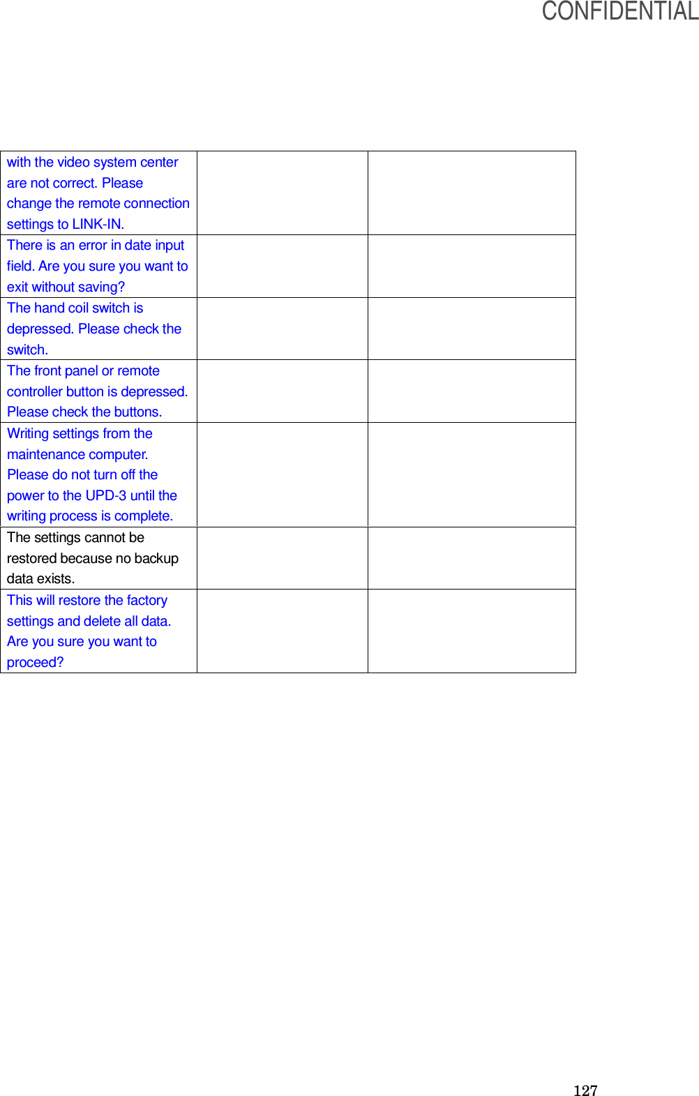
![122 Chapter 9 Troubleshooting If the endoscope position detecting unit is visibly damaged, does not function as expected, or is found to have irregularities during the inspection described in Chapter 3, “Inspection” and Chapter 7, “Installation and Connection”, or the use described in Chapter 4, “Operation”, do not use the endoscope position detecting unit and contact Olympus. Some problems that appear to be malfunctions may be correctable by referring to Section 9.1, “Troubleshooting guide”. If the problem cannot be resolved by the described remedial action, stop using the endoscope position detecting unit and contact Olympus. [DANGER] Never use the endoscope position detecting unit if an abnormality is suspected. Damage or irregularity in the instrument may compromise patient or user safety and may result in more severe equipment damage. 9.1 Troubleshooting guide The following table shows the possible causes of and countermeasures against troubles that may occur due to equipment setting errors or deterioration of consumable. Troubles or failures other than those listed in the following table need repair. As repair performed by persons who are not qualified by Olympus could cause patient or user injury and/or equipment damage, be sure to contact Olympus for repair. Irregularity description Possible cause Solution The endoscope position detecting unit is not connected to a hospital-grade power outlet. Connect the endoscope position detecting unit to the power outlet using the power cord. The endoscope position detecting unit cannot be turned on. Power is not supplied to the hospital-grade power outlet. Supply power properly to the power outlet. The setup menu is being displayed. Display the scope model as described in “Saving and recalling the display setup”. The scope model is not displayed on the monitor. The UPD cable is not connected. Connect the UPD cable. CONFIDENTIAL](https://usermanual.wiki/Olympus-Medical-Systems/UPD-3.Instruction-Manual/User-Guide-1366365-Page-122.png)
![128 9.2 Returning the endoscope position detecting unit for repair [CAUTION] Olympus is not liable for any injury or damage which occurs as a result of repairs attempted by non-Olympus personnel. When returning the video system center for repair, contact Olympus. With the video system center, include a description of the malfunction or damage and the name and telephone number of the individual at your location who is most familiar with the problem. Include a repair purchase order. [NOTE] When the accessories of the position detecting unit, contact Olympus to purchase a replacement. CONFIDENTIAL](https://usermanual.wiki/Olympus-Medical-Systems/UPD-3.Instruction-Manual/User-Guide-1366365-Page-128.png)
![137 ○ Electromagnetic immunity compliance information and recommended electromagnetic environments [NOTE] UT is the a.c. mains power supply prior to application of the test level. CONFIDENTIAL](https://usermanual.wiki/Olympus-Medical-Systems/UPD-3.Instruction-Manual/User-Guide-1366365-Page-137.png)
![138 ○ Cautions and recommended electromagnetic environment regarding portable and mobile RF communications equipment such as a cellular phones. [NOTE] • Where “P” is the maximum output power rating of the transmitter in watts (W) according to the transmitter manufacturer and “d” is the recommended separation distance in meters (m). • This instrument complies with the requirements of IEC 60601-1-2: 2001. However, under electromagnetic environment that exceeds its noise level, electromagnetic interference may occur on this instrument. • Electromagnetic interference may occur on this instrument near a high-frequency electrosurgical equipment and/or other equipment marked with the following symbol: CONFIDENTIAL](https://usermanual.wiki/Olympus-Medical-Systems/UPD-3.Instruction-Manual/User-Guide-1366365-Page-138.png)
![139 ○ Recommended separation distance between portable and mobile RF communications equipment and this instrument [NOTE] The guidance may not apply in some situations. Electromagnetic propagation is affected by absorption and reflection from structures, objects and people. Portable and mobile RF communications equipment such as cellular phones should be used no closer to any part of this instrument, including cables than the recommended separation distance calculated from the equation applicable to the frequency of the transmitter. FCC information This device complies with part 15 of the FCC Rules. Operation is subject to the following two conditions: (1) This device may not cause harmful interference, and (2) this device must accept any interference received, including interference that may cause undesired operation. FCC ID:S8QUPD-3 IC information This equipment complies with the IC RSS210. IC: 4763B-UPD3 FCC warnings Change or modifications not expressly approved by the party responsible for compliance could void the user's authority to operate the equipment. All interface cables used to connect peripherals must be shielded in order to comply with the limits for a digital device pursuant to Subpart B of Part 15 of FCC Rules. IC note Operation is subject to the following two conditions: (1) this device may not cause interference, and (2) this device must accept any interference, including interference that may cause undesired operation of the device. CONFIDENTIAL](https://usermanual.wiki/Olympus-Medical-Systems/UPD-3.Instruction-Manual/User-Guide-1366365-Page-139.png)