Olympus Medical Systems UPD-3 Endoscope Position Detecting Unit User Manual Instruction Manual
Olympus Medical Systems Corp. Endoscope Position Detecting Unit Instruction Manual
Contents
- 1. Instruction Manual
- 2. Excerpt of the user manual
Instruction Manual

1
DRAFT
INSTRUCTIONS
ENDOSCOPE POSITION DETECTING UNIT
UPD-3
USA: CAUTION: Federal law restricts this
device to sale by or on the order of a physician.
(For 220 – 240V type equipment)
CONFIDENTIAL
2
Contents
Labels and Symbols
Important Information — Please Read Before Use
Summary of Equipment Functions
Chapter 1 Checking the Package Contents
Chapter 2 Nomenclature and Functions
Chapter 3 Inspection
Chapter 4 Operation
Chapter 5 Functions
Chapter 6 Care, Storage, and Disposal
Chapter 7 Installation and Connection
Chapter 8 Function setup
Chapter 9 Troubleshooting
Appendix
CONFIDENTIAL
3
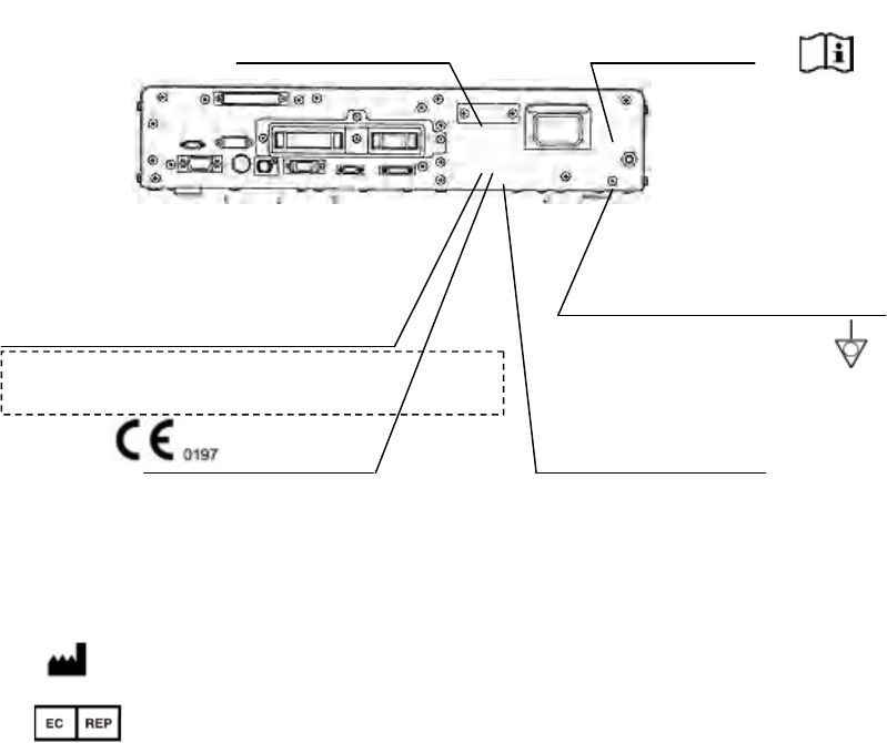
Labels and Symbols
Safety-related labels and symbols are attached on the locations shown below. If labels or
symbols are missing or illegible, contact OLYMPUS.
Serial number plate
Potential equalization terminal
The product name and electric rating
Endoscope Position Detecting Unit UPD-3
Input: 100-240V 50/60Hz 100VA
CE marking Manufacturer name
○Back cover of this instruction manual
Manufacturer
Authorized representative in the European Community
Caution that only the exclusive
cable can be connected.
CONFIDENTIAL
4
Important Information — Please Read Before
Use
Intended use
This instrument has been designed to be used with Olympus endoscopes system for detection
and displaying the shape of inserted endoscope.
Instruction manual
This instruction manual contains essential information on using this endoscope position
detecting unit safely and effectively. Before use, thoroughly review this manual and the
manuals of all equipment which will be used during the procedure and use the equipment
as instructed.
Keep this and all related instruction manuals in a safe, accessible location. If you have any
questions or comments about any information in this manual, please contact Olympus.
CONFIDENTIAL
5
○Terms used in this manual
Wall mains outlet:
The wall mains outlet is a wall AC mains power outlet socket having the exclusive terminal
for grounding
Isolation transformer:
The isolation transformer is a safety device that is used to isolate noninsulated equipment
with potentially high leakage currents to decrease the possibility of electric shock.
Scope model:
The scope model is a computer graphic image that models the shape of the endoscope
insertion tube.
CONFIDENTIAL
6
User qualifications
If there is an official standard on user qualifications to perform endoscopy and endoscopic
treatment that is defined by the medical administration or other official institutions, such
as academic societies on endoscopy, follow that standard. If there is no official qualification
standard, the operator of this instrument must be a physician approved by the medical
safety manager of the hospital or person in charge of the department (department of
internal medicine, etc.).
The physician should be capable of safely performing the planned endoscopy and
endoscopic treatment following guidelines set by the academic societies on endoscopy, etc.,
and considering the difficulty of endoscopy and endoscopic treatment. This manual does not
explain or discuss endoscopic procedures.
Instrument compatibility
Refer to the “System chart” in the Appendix to confirm that this balloon control unit is
compatible with the ancillary equipment being used. Using incompatible equipment can
result in patient injury and/or equipment damage. Also review the manuals of all
equipment that will be used during the procedure and use the equipment as instructed.
This instrument complies with EMC standard for medical electrical equipment; edition 2
(IEC 60601-1-2: 2001) and edition 3 (IEC 60601-1-2: 2007). However, when connected with
an instrument that complies with EMC standard for medical electrical equipment; edition
1 (IEC 60601-1-2: 1993), the whole system complies with edition 1.
Repair and modification
This endoscope position detecting unit does not contain any user-serviceable parts. Do not
disassemble, modify or attempt to repair it; patient or operator injury, equipment damage
and/or the impossibility to obtain the expected functionality can result. Some problems that
appear to be malfunctions may be correctable by referring to Chapter 9, “Troubleshooting”.
If the problem cannot be resolved using the information in Chapter 9, contact Olympus.
This instrument is to be repaired by Olympus technicians only.
CONFIDENTIAL
7
Signal words
The following signal words are used throughout this manual:
[DANGER]
Indicates an imminently hazardous situation which, if not avoided, will result in death or
serious injury.
[WARNING]
Indicates a potentially hazardous situation which, if not avoided, could result in death or
serious injury.
[CAUTION]
Indicates a potentially hazardous situation which, if not avoided, may result in minor or
moderate injury. It may also be used to alert against unsafe practices or potential
equipment damage.
[NOTE]
Indicates additional helpful information.
Dangers, warnings and cautions
Follow the dangers and cautions given below when handling this endoscope position
detecting unit. This information is to be supplemented by the dangers and cautions given
in each chapter.
[DANGER]
•As a TYPE BF applied part, the endoscope connected to this instrument must never be
applied directly to the heart. Leakage current from the TYPE BF applied part may be
dangerous and cause ventricular fibrillation or otherwise seriously affect the cardiac
function of the patient. Accordingly, always adhere to the following:
− Never apply the endoscope connected to this instrument to the heart or any area near the
heart.
− Never allow an EndoTherapy accessory or another endoscope applied to or near the heart
to come in contact with the endoscope connected to this instrument.
•Strictly observe the following precautions. Failure to do so may place the patient and
medical personnel in danger of electric shock.
− When this endoscope position detecting unit is used to examine a patient, do not allow
metal parts of the endoscope or its accessories to touch metal parts of other system
components. Such contact may cause unintended current flow to the patient.
− Keep fluids away from all electrical equipment. If fluids are spilled on or into the unit,
stop operation of the endoscope position detecting unit immediately and contact Olympus.
CONFIDENTIAL
8
− Do not prepare, inspect or use this endoscope position detecting unit with wet hands.
• Never install and operate the endoscope position detecting unit in locations where:
− the concentration of oxygen is high;
− oxidizing agents (such as nitrous oxide (N2O)) are present in the atmosphere;
− flammable gases are present in the atmosphere;
− flammable liquids are near.
Otherwise, explosion or fire may result because this endoscope position detecting unit is
not explosion-proof.
• This instrument generates AC magnetic fields. To prevent critical effects on patients, be
sure to adhere to the following:
− Never use the instrument on a patient with a pacemaker. The AC magnetic fields
generated by the instrument may cause malfunction or damage to the pacemaker, exerting
critical effects to the cardiac function of the patient.
− Never use the instrument on pregnant women and women suspected of being pregnant.
The effects of the AC magnetic field generated by the instrument on the unborn baby have
not yet been determined.
CONFIDENTIAL

9
[WARNING]
• Never insert anything into the ventilation grills of the endoscope position detecting unit.
It can cause an electric shock and/or fire.
• This product may interfere with other medical electronic equipment used in combination
with it. Before use, refer to the Appendix to confirm the compatibility of this instrument
with all equipment to be used.
• Do not use this product in any place where it may be subject to strong electromagnetic
radiation (for example, in the vicinity of a microwave therapeutic device, MRI, wireless set,
short-wave therapeutic device, cellular/portable phone, etc.). This may impair the
performance of the product.
[CAUTION]
• Do not touch the electrical contacts inside the instrument’s connectors. Otherwise,
equipment damage and/or malfunction can occur.
• Do not use a pointed or hard object to press the buttons on the front panel and/or
keyboard. This may damage the buttons.
• Do not apply excessive force to the connectors. Otherwise, a failure of an electrical contact
may result in a malfunction.
• This instrument emits RF (Radio Frequency) energy to supply data by radio
communication. Therefore, it may cause electromagnetic interference in nearby electronic
equipment, and is labeled with the following symbol. If electromagnetic interference occurs,
mitigation measures may be necessary, such as moving the electronic equipment away,
reorienting or relocating this instrument, or shielding the location.
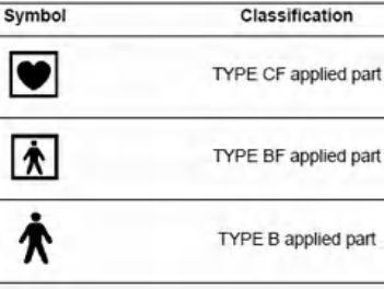
[NOTE]
• As defined by the international safety standard (IEC 60601-1), medical electrical
equipment is classified into the following types: TYPE CF applied part (the instrument can
safely be applied to any part of the body, including the heart), and TYPE B/BF applied part
(the instrument can safely be applied to any organ except the heart). The part of the body
that an endoscope or electrosurgical accessory can safely be applied to depends on the
classification of the equipment to which the instruments are connected. Before beginning
the procedure, check the current leakage classification type of each instrument to be used
for the procedure. Classification types are clearly specified in the instruments' instruction
manuals.
CONFIDENTIAL
10
• When endoscopes are used with endoscope accessories connected with other medical
electronic equipment, the leakage currents may increase.
CONFIDENTIAL
11
Summary of Equipment Functions
This instrument is equipment that detects and displays the spatial image of an endoscope.
Some of the functions of this instrument described below are enabled only when the
required equipment are connected to this instrument. For more details, refer to the
instruction manuals for this instrument and the other instruments connected.
Displaying the spatial image of the endoscope
The spatial image of the endoscope is displayed on the monitor in real time.
Zooming in or out and rotating the scope model
The scope model displayed on the monitor can be zoomed in or out and rotated.
Splitting the screen
The scope model can be displayed on two screens by splitting the screen.
Saving and selecting the screen display
Up to 20 presets of the display can be saved, and one of them can be selected to use.
Hand coil
The relative position between the hand coil (MAJ-1859, optional) and endoscope can be
detected.
View tracking
The orientation of the patient’s body can be detected by attaching the reference plate
(MAJ-1860, optional) to the patient’s body, and the scope model can be displayed in fixed
direction.
CONFIDENTIAL
12
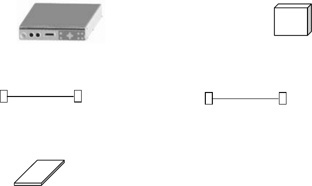
Chapter 1 Checking the Package Contents
Match all items in the package with the components shown below. Inspect each item for
damage. If the instrument is damaged, a component is missing or you have any questions,
do not use the instrument; immediately contact Olympus.
ENDOSCOPE POSITION DETECTING UNIT RECEIVER DISH
(UPD-3) (MAJ-1868)
RECEIVER DISH CABLE (MAJ-1875) UPD CABLE(MAJ-1881)
Instruction manual
CONFIDENTIAL
13
Chapter 2 Nomenclature and Functions
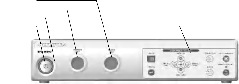
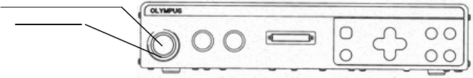
2.1 Front panel
4. Reference plate terminal
3. Hand coil terminal
2. Power indicator
1. Power switch Control panel
1. Power switch
Press to turn the endoscope position detecting unit ON or OFF.
2. Power indicator
This indicator lights up when the main unit is ON.
3. Hand coil terminal
The hand coil (MAJ-1859) is connected to this terminal.
4. Reference plate terminal
The reference plate (MAJ-1860) is connected to this terminal.
CONFIDENTIAL
14
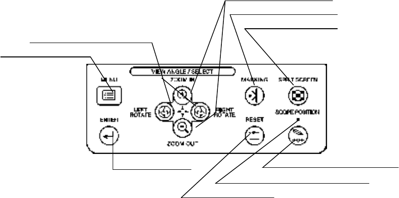
2.2 Control panel
3. Zoom buttons
4.Boolmark button
5. Split screen button
2. Rotate left / Rotate right button
1. Menu button
9.Enter button 6.Scope position button
7. Scope position indicator
8. Reset button
1. Menu button
This button is pressed to display or exit from the menu list.
2. Rotate left / Rotate right button
When the scope model display is active, these buttons are pressed to rotate the scope model
or to change the posture of the figure image. When the menu list is active, these buttons
are pressed to select a menu.
3. Zoom buttons
These buttons are pressed to zoom the scope model display in or out (i.e., magnify or reduce
it). When the menu list is active, these buttons are pressed to select a menu.
4. Bookmark button
This button is pressed to mark on the display length.
5. Split screen button
This button is pressed to change between split-screen and single-screen display alternately.
6. Scope position button
This button is pressed to set or release the start position of the scope model.
7. Scope position indicator
This indicator lights up when the start position of the scope model has been set.
8. Reset button
CONFIDENTIAL
15
This button is pressed to initialize the scope model display, and the posture of the figure
image.
9. Enter button
This button is pressed to determine the category in the menu list.
CONFIDENTIAL
16
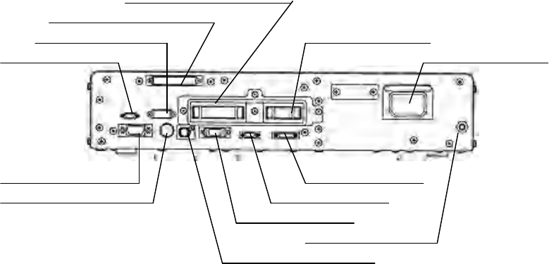
2.3 Rear panel
4. Scope/probe terminal
3. Receiver dish terminal
2. Connection unit terminal 5. CLV terminal
1. Remote control terminal 6. AC power inlet
13. XGA OUT terminal 8. LINK IN terminal
12. Y/C OUT terminal 9. LINK OUT terminal
10. CV remote terminal
7. Potential equalization terminal
11. SDI OUT terminal
1. Remote control terminal
This terminal is the receptacle for the remote control cable to connect the endoscope
position detecting unit to the remote control.
2. Connection unit terminal
The MP extension cable (MAJ-Y0062) is connected to this terminal.
3. Receiver dish terminal
The receiver dish cable (MAJ-1875) is connected to this terminal.
4. Scope/probe terminal
The UPD cable (MAJ-1881) is connected to this terminal.
5. CLV terminal
This terminal is provided for the connection to the future Olympus light source and cannot
be used for the present.
6. AC power inlet
Connect the provided power cord to supply AC power via this inlet.
7. Potential equalization terminal
For safety purposes, this terminal is connected to a potential equalization busbar of the
electrical installation.
8. LINK IN terminal
This terminal is provided for the connection to the future Olympus equipment and cannot
CONFIDENTIAL
17
be used for the present.
9. LINK OUT terminal
This terminal is provided for the connection to the future Olympus equipment and cannot
be used for the present.
10. CV remote terminal
The patient data signal from the video system center is input via this terminal. The UPD
data transfer cable (MAJ-604) or the data transfer cable (MAJ-1260)* is connected to this
terminal.
11. SDI OUT terminal
The video signal (serial digital interface / SDI signal) is output via this terminal.
12. Y/C OUT terminal
The video signal (Y/C signal) is output via this terminal.
13. XGA OUT terminal
The video signal (XGA signal) is output via this terminal.
* This product may not be available in some areas.
CONFIDENTIAL
18
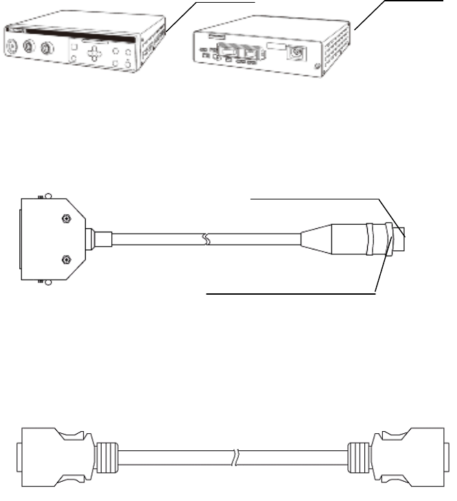
2.4 Side panels
Ventilation grills Ventilation grills
Front side Rear side
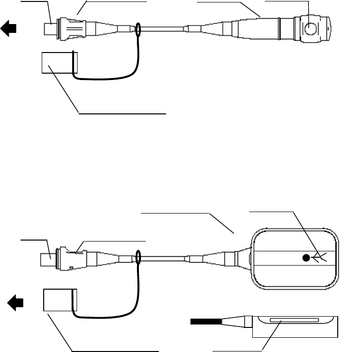
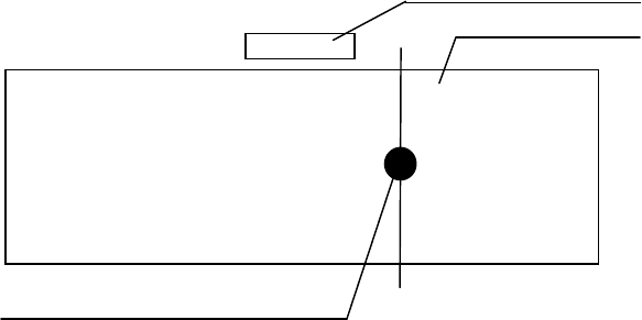
2.5 UPD cable (MAJ-1881)
Notch
Position detecting connector
2.6 Receiver dish cable (MAJ-1875)
CONFIDENTIAL
19
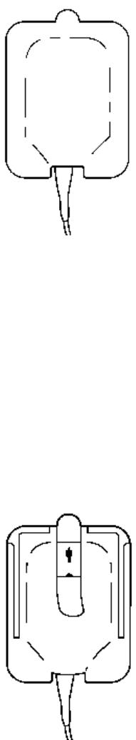
2.7 Receiver dish (MAJ-1868)
Front side Rear side
Front
Cable terminal
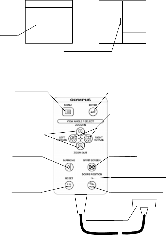
2.8 Remote control (MAJ-1890 Option)
1. Menu key 2.Enter key
3. Rotate left / Rotate right key
9. Zoom keys
8. Bookmark key 4. Split screen key
5. Scope position indicator
7. Reset key 6. Scope position key
10. Connector
OLYMPUS
CONFIDENTIAL
20
1. Menu key
This key is pressed to display or exit from the menu list.
2. Enter key
This button is pressed to determine the category in the menu list.
3. Rotate left / Rotate right key
When the scope model display is active, these keys are pressed to rotate the scope model or
to change the posture of the figure image. When the menu list is active, these keys are
pressed to select a menu.
4. Split screen key
This key is pressed to change between split-screen and single-screen display alternately.
5. Scope position indicator
This indicator lights up when the start position of the scope model has been set.
6. Scope position key
This key is pressed to set or release the start position of the scope model.
7. Reset key
This key is pressed to initialize the scope model display, and the posture of the figure
image.
8. Bookmark key
This button is pressed to mark on the display length.
9. Zoom keys
These keys are pressed to zoom the scope model display in or out (i.e., magnify or reduce it).
When the menu list is active, these keys are pressed to select a menu.
10. Connector
This connector connects the endoscope position detecting unit.
CONFIDENTIAL
21
2.9 Hand coil (MAJ-1859) (Option)
Arrow Connector Marker section Switch
To endoscope
position
detecting
unit
Water-resistant cap
2.10 Reference plate (MAJ-1860) (Option)
Plate section Human-shaped index marking
Arrow Connector
To endoscope
position
detecting
unit
Water-resistant cap Slit
CONFIDENTIAL

22
2.11 Reference plate cover (MAJ-1880) (Option)
Reference plate cover, top surface (blue) Tab
Perforation
Lining paper (backside) Lining paper (inside)
CONFIDENTIAL
23
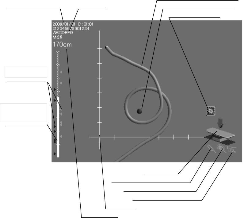
2.12 Screen display
○For the operating table image
1. Scope model
12. Current date and time 13. Patient data 2.Marker model
3. Tracking icon
4. View point indicator (operating table image)
5. Marker connection icon
6. Plate connection icon
7. Scope connection icon
8. Gauge
9. Display length
10. Marking
gauge
11. Marking
CONFIDENTIAL
24
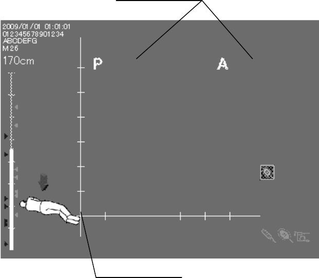
○For the figure image
14. A-P indicator
15. Viewpoint indicator (figure model)
CONFIDENTIAL
25
1. Scope model
The shape of the endoscope’s insertion tube will be displayed when the endoscope’s
insertion tube is moved in front of the coil unit.
2. Marker model
The position of the hand coil (MAJ-1859) will be displayed when the hand coil is connected
and moved in front of the coil unit.
3. Tracking icon
The indicator will be displayed in the tracking display mode (see Section 5.9, “View
tracking”).
4. Viewpoint indicator (Operating table image)
The arrow indicator and operating table image show the angle in which the scope model on
the screen is viewed. This indicator appears when “Operating table image” is selected from
“Setting the viewing image” in the setup menu (see “User preset”).
5. Marker connection icon
The indicator will be displayed when the hand coil is connected. The color represents the
connection and detection status (see Section 5.5, “Connection indicators”).
6. Plate connection icon
The indicator will be displayed when the reference plate is connected. The color represents
the connection and detection status (see Section 5.5, “Connection indicators”).
7. Scope connection icon
The indicator will be displayed when an applicable endoscope or position detecting probe is
connected to the endoscope position detecting unit. The color represents the connection and
detection status (see Section 5.5, “Connection indicators”).
8. Gauge
The gauge is used as a reference for identifying the size of the displayed scope model. It will
be displayed when “Enable information display” is set (see Section 8.3, “User preset”).
9. Display length
The display length shows an actual length of the scope model displayed on the screen. (For
the display range, see Section 4.2, “Scope model display range”.) It will be displayed when
“Enable information display” is set (see Section 8.3, “User preset”). The display length does
not show the actual length of the endoscope inserted in the patient’s body.
10. Marking gauge
The display length is shown with the vertical axis. It will be displayed when “Enable
information display” is set (see Section 5.6, “Bookmark”).
CONFIDENTIAL
26
11. Marking
Markings can be put beside the marking gauge according to the points where you want to
mark while inserting the endoscope into the patient. It will be displayed when “Enable
information display” is set (see Section 5.6, “Bookmark”).
12. Current date and time
Current date and time of the day will be displayed when “Enable information display” is set
(see Section 8.3, “User preset”).
13. Patient data
The data will be displayed when the video system center is connected and when “Enable
information display” is set (see Section 8.3, “User preset”).
14. A-P indicator
The indicator is displayed when “Figure image” is selected from “Setting the viewing
image” in the setup menu. The indicator shows the anterior and posterior sides of the
figure image.
15. Viewpoint indicator (Figure image)
The arrow indicator and figure image show the angle in which the scope model on the
screen is viewed. This indicator appears when “Figure image” is selected from “Setting the
viewing image” in the setup menu (see Section 8.3, “User preset”).
○ Figure image
The figure image is displayed when “Figure image” is selected from “Setting the viewing
image” in the setup menu. The viewpoint indicator is displayed with a relative angle
against the figure image on the screen. The posture of the figure image can be changed as
the patient’s posture changes.
[NOTE]
The viewpoint indicator arrow shows the angle in which the scope model on the screen is
viewed regardless of the posture of the figure image. The view angle is indicated against
the receiver dish.
CONFIDENTIAL

27
Chapter 3 Inspection
[WARNING]
Before each case, inspect this endoscope position detecting unit as instructed below. Inspect
other equipment to be used with this endoscope position detecting unit as instructed in
their respective instruction manuals. Should any irregularity be observed, do not use the
endoscope position detecting unit and see Chapter 9, “Troubleshooting”. If the irregularity
is still observed after consulting Chapter 9, contact Olympus. Damage or irregularities may
compromise patient or user safety and may result in more severe equipment damage.
Prepare the endoscope position detecting unit and other ancillary equipment before each
particular case. Refer to the respective instruction manual for each piece of equipment.
3.1 Inspection work flow
Please see the inspection work flow in Figure 3.1 below. Follow each step of the work flow
for inspection of the light source before use.
1. Check if the endoscope position detecting unit is installed in an appropriate
location.→ Section 3.2, “Inspection of the installation location”
↓ 2. Confirm that the endoscope position detecting unit is turned ON normally.
→ Section 3.3 “Turning power ON”
↓ 3. Confirm the contents in the screen display.
→ Section 3.4, “Inspection of the screen display”
↓ 4. Inspect all necessary functions.
↓ 5. Turn OFF the endoscope position detecting unit.
→ Section 3.7, “Power OFF”
CONFIDENTIAL
28
3.2 Inspection of the installation location
Check if the endoscope position detecting unit (UPD-3) is installed in an appropriate
location.
1. Confirm that no video monitor or PC monitor is near the endoscope position detecting
unit. Keep a distance of at least 30 cm between the video monitor or the PC monitor and
the endoscope position detecting unit.
[CAUTION]
If a video monitor or PC monitor is located near the endoscope position detecting unit, the
scope model display may be distorted or deformed due to the strong magnetic fields
produced by the monitor.
Keep the endoscope or the position detecting probe, the reference plate, and/or the hand coil
connected with the main unit away from another main unit at least 2 m when two or more
endoscope position detecting units are used. Otherwise, the scope model display may be
extremely distorted or deformed due to the strong magnetic fields produced by one another.
If the distance between the two endoscope position detecting units is less than 2 m,
changing the frequencies used for position detection may allow the use of two or more
endoscope position detecting units. When two or more endoscope position detecting units
are used with a distance of less than 2 m, contact Olympus.
2. Confirm that no large metallic object is near the coil unit of the endoscope position
detecting unit. Keep a distance of at least 30 cm between the large metallic object and the
endoscope position detecting unit.
[CAUTION]
If a metallic object is located near the endoscope position detecting unit, the scope model
display may also be distorted or deformed.
3.3 Turning power ON
[WARNING]
• Keep the endoscope or the position detecting probe, the reference plate, and/or the hand
coil connected with the main unit away from another main unit at least 2 m when two or
more endoscope position detecting units are used. Otherwise, the scope model display may
be extremely distorted or deformed.
• When two or more endoscope position detecting units are used, do not turn the main
units ON at the same time. Otherwise, the scope model display may be extremely distorted
or deformed.
CONFIDENTIAL
29
1. Confirm that the ventilation grills on the right side and left side panels of the endoscope
or the endoscope position detecting unit are not covered with dust or other materials.
2. Confirm that the endoscope or the position detecting probe is connected to the main unit.
[NOTE]
For connecting the endoscope or the position detecting probe to the main unit, refer to
Section 4.4, “Connection of the endoscope or the position detecting probe”.
3. Press the power switch of the instrument. The power indicator lights up (see Figure).
Power switch
Power indicator
○ If the power fails to come ON
If the power fails to come ON, turn the endoscope position detecting unit OFF. Then,
confirm that the power cord is connected firmly. Then, turn the endoscope position
detecting unit ON again. If the power still fails to come ON, contact Olympus.
CONFIDENTIAL

30
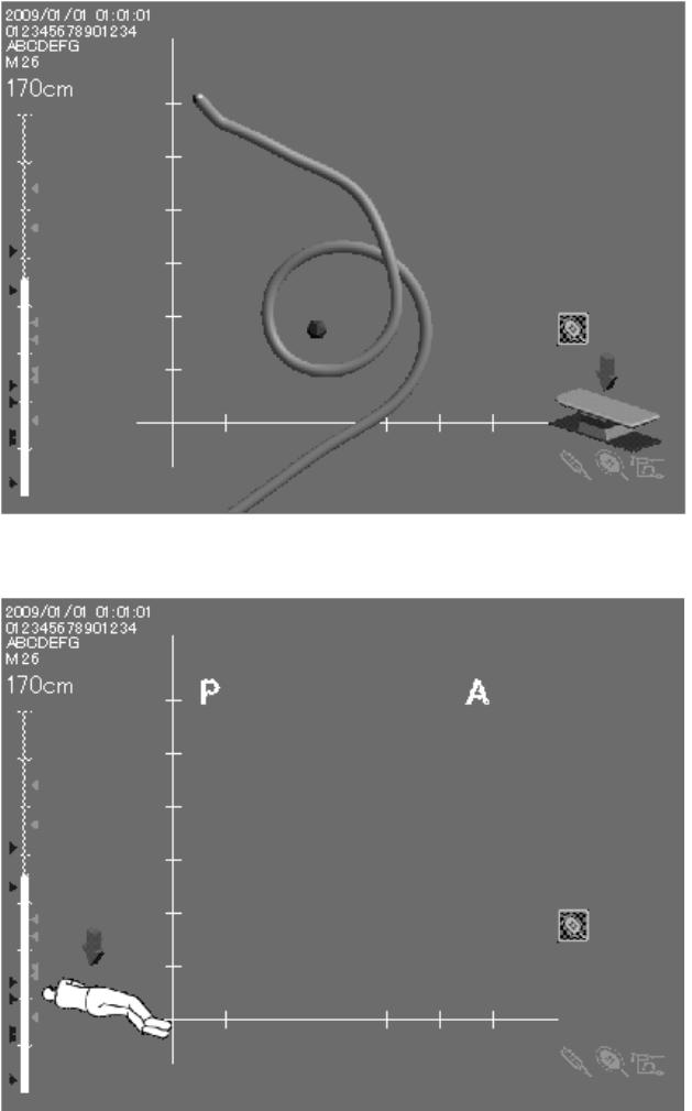
3.4 Inspection of the screen display
1. Confirm that the LCD monitor shows the endoscope position display as shown in Figure.
The screen display varies depending on the setup of the main unit or connection status of
equipment. For details, see Section 2.12, “Screen display”.
2. Change the shape of the endoscope’s insertion tube or the position detecting probe’s
insertion tube into a circular or straight shape in front of the coil unit of the endoscope
position detecting unit. Then confirm that the shape of the scope model is the same as the
shape of the endoscope’s insertion tube. Also, confirm that the angle of the viewpoint
indicator is the same as the angle in which the scope model on the screen is viewed.
Confirm that the shape of the scope model is the same as the shape of the endoscope’s
insertion tube even when the receiver dish is facing down or up.
3. Confirm that the displayed date and time are correct. If correction is required, follow the
procedure in “Setting the date and time”
[CAUTION]
The posture of the figure image on the screen must always be set to be equal to the actual
posture of the patient. If the posture of the figure image on the screen is not equal to the
posture of the patient, the scope model display may be incorrectly orientated.
Facing down
Facing up
CONFIDENTIAL
31
For the operating table image
For the figure image
CONFIDENTIAL
32
3.5 Inspection of the hand coil (MAJ-1859)
1. Confirm that there is no noticeable deformation, scratch, or crack on the marker section.
2. Confirm that there is no noticeable deformation, scratch, or crack on the hand coil cover
(MAJ-1879).
3.6 Inspection of the reference plate (MAJ-1860)
1. Confirm that there is no noticeable deformation, scratch, or crack on the plate section.
2. Confirm that there is no scratch, break, or fissure on the reference plate belt
3.7 Power OFF
Press the power switch of the instrument (see Figure) to turn the instrument OFF. The
indicator above the switch goes off.
CONFIDENTIAL
33
Chapter 4 Operation
This chapter explains the work flow of endoscopic observation using the endoscope position
detecting unit. For information on how to use the functions that are not explained in this
chapter, refer to chapter 5, “Functions”.
The operator of the endoscope position detecting unit must be a physician or medical
personnel under the supervision of a physician and must have received sufficient training
in clinical endoscopic techniques. This manual, therefore, does not explain or discuss
clinical endoscopic procedures. It only describes basic operation and precautions related to
the operation of the endoscope position detecting unit.
[DANGER]
The endoscope position detecting unit is designed only to assist the insertion of an
endoscope. Never insert the endoscope into the patient’s body by observing only the
endoscope position display of the endoscope position detecting unit. Be sure to observe the
endoscopic image and insert the endoscope while confirming safety. If the endoscope is
inserted without observing the endoscopic image, patient injury could result.
[WARNING]
• Be sure to wear protective equipment such as eye wear, face mask, moisture-resistant
clothing and chemical-resistant gloves that fit properly and are long enough so that your
skin is not exposed. Otherwise, dangerous chemicals and/or potentially infectious material
such as blood and/or mucus of the patient may cause an infection.
• Anytime you observe an irregularity in this endoscope position detecting unit, stop using
it immediately, turn it OFF, and solve the problem according to Chapter 9,
“Troubleshooting”. If the problems cannot be resolved by the described remedial action, do
not use this endoscope position detecting unit again and immediately contact Olympus.
Using a defective endoscope position detecting unit may cause patient injury.
• When the monitor display freezes, such as when the displayed time will not change or if
the scope model will not move when the endoscope’s insertion tube is moved, or when the
switches on the control panel are not accepted, turn the endoscope position detecting unit
OFF and ON again. If the problem still occurs, contact Olympus.
• When using spray-type medical agents such as lubricant, anesthetic, or alcohol, use them
away from the endoscope position detecting unit so that the medical agents do not contact
the endoscope position detecting unit. Medical agents might enter the endoscope position
detecting unit through the ventilation grills and cause the failure.
• Do not use a humidifier near the endoscope position detecting unit as dew condensation
possibly might occur and it may cause the failure.
• Use only Olympus high-frequency electrosurgical equipment with this unit.
Non-Olympus equipment can cause interference on the monitor display or a loss of the
scope model.
CONFIDENTIAL
34
[CAUTION]
• Do not use this endoscope position detecting unit in locations exposed to strong
electromagnetic radiation (e.g., in the vicinity of microwave therapeutic equipment, MRI,
short-wave therapeutic equipment, radio equipment, or cellular/portable phone). Damage
to the endoscope position detecting unit may result. Electromagnetic radiation can
interfere with the monitor display.
• When the endoscope position detecting unit is used on a patient with an artificial
material implant, the displayed scope model shape may differ from its actual shape.
• Do not approach the following equipment with a magnetic storage medium (magnetic
card, floppy disk, etc.): the endoscope, the position detecting probe, the reference plate
(MAJ-1859), or the hand coil (MAJ-1860) connected to the endoscope position detecting
unit. Otherwise, the data stored on the magnetic storage medium may be destroyed or lost
due to the AC magnetic fields generated by these devices.
CONFIDENTIAL

35
4.1 Operation flow
Please see the operation work flow in Figure below. Follow each step of the work flow for
using the endoscope position detecting unit.
1. Adjust the position of the receiver dish.
→ ”Adjusting the position of the receiver dish”
↓ 2. Connect the endoscope or the position detecting probe to the main unit.
→ Section 4.4, “Connection of the endoscope or the position detecting probe”
↓ 3. Inspect the instruments before use.
→ Chapter 3, “Inspection”
↓ 4. Connect the hand coil (MAJ-1859).
→ Section 5.8 ”Connection of the hand coil (MAJ-1859)
When the hand coil is not used, this procedure is unnecessary.
↓ 5. Connect the reference plate (MAJ-1860).
→ Section 5.10 ”Connection of the reference plate(MAJ-1860)”
When the reference plate is not used, this procedure is unnecessary.
↓ 6. Turn the main unit and equipment ON.
→ Section 3.3, “Turning power ON”
↓ 7. Select the screen display setup.
→ When the previous setup is selected, this procedure is unnecessary.
↓ 8. Perform examination.
→ For details on each function, refer to Chapter 5, “Functions".
↓ 9. Disconnect the endoscope or the position detecting probe.
→ Section 4.8, “Operation at the end of an examination”
↓ 10. Care after use.
→ Chapter 6, “Care, storage and disposal”
CONFIDENTIAL
36
4.2 Scope model display range
Scope model and actual positioning
The relationship between the monitor screen display and the actual positioning of the
endoscope position detecting unit (UPD-3) during the initial setup shown in Figure
Monitor screen
In the “From the top” display mode In the “From the bottom” display mode
Actual positioning
Receiver dish
(Top View)
Operating table
For the display modes, see “Setting the display mode”
Y
X
Z
Y
Y
X
X
Z
Z
Y
Y
X
X
Z
Z
CONFIDENTIAL
37
The start position of scope model and actual positioning
The position where the scope model display starts on the monitor screen is variable
depending on whether the reference plate (MAJ-1860) is connected and/or the scope model
display range is set.
For setting the scope model display range, see Section 5.7, “Setting the scope model display
range”
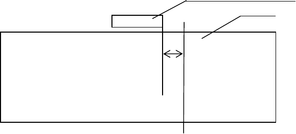
○When the reference plate is not connected and the scope model
display range is not set
Receiver dish
(Top view)
Operating table
When the receiver dish is viewed from the front, the position A located at about 13 cm to
the right from its right end (see Figure) corresponds to the start position of the scope model
on the screen. However, the scope model will not be displayed when the distal end of the
endoscope is located to the right of line A. The center of the bottom of the monitor display
corresponds to the start position of the scope model.
13cm
A
CONFIDENTIAL
38
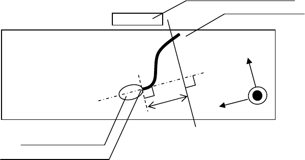
○When the reference plate is connected and the scope model display
range is not set
Receiver dish
(Top view)
Operating table
Reference plate
Cable outlet
When the endoscope position detecting unit is viewed from the front, the position B located
at 6 cm toward the reference plate from its cable outlet (see Figure) corresponds to the start
position of the scope model on the screen. The part of the endoscope located to the left of
line B facing the endoscope position detecting unit will be displayed as the scope model.
However, the scope model will not be displayed when the distal end of the endoscope is
located to the right of line B. The center of the bottom of the monitor display corresponds to
the start position of the scope model. The coordinate axis on the screen corresponds to the
coordinate axis as shown in Figure.
6cm
B
Z
X
Y
CONFIDENTIAL
39
○When the reference plate is not connected and the scope model
display range is set
Receiver dish
(Top view)
Operating table
Set position of the display range
When the display range is set, the set position C (see Figure) becomes the start position of
the scope model, and the part of the endoscope located to the left of line C facing the
endoscope position detecting unit will be displayed as the scope model. However, the scope
model will not be displayed when the distal end of the endoscope is located to the right of
line C. The center of the bottom of the monitor display corresponds to the start position of
the scope model. If the display range is not set, the start position of the scope model
becomes identical to “When the reference plate is not connected and the scope model
display range is not set”
For setting the display range, refer to Section 5.7, “Setting the scope model display range”
C
CONFIDENTIAL

40
○When the reference plate is connected and the scope model display
range is set
Receiver dish
(Top view)
Operating table
Reference plate
Cable outlet Set position of the display range
When the display range is set, the set position D (see Figure) becomes the start position of
the scope model, and the part of the endoscope located to the left of line D facing the
endoscope position detecting unit will be displayed as the scope model. However, the scope
model will not be displayed when the distal end of the endoscope is located to the right of
line D. The center of the bottom of the monitor display corresponds to the start position of
the scope model. The coordinate axis on the screen corresponds to the coordinate axis as
shown in Figure. If the display range is not set, the start position of the scope model
becomes identical to “When the reference plate is connected and the scope model display
range is not set”
D
Z
X
Y
CONFIDENTIAL
41
4.3 Adjusting the position of the receiver dish
[WARNING]
•When adjusting the height of the receiver dish, or when adjusting the height of the
operating table if it is adjustable, be careful not to have your hand, foot, or the patient’s
body caught between the receiver dish and the operating table. Otherwise, operator and/or
patient injury may result.
Be careful not to have your fingers caught between the arms when they are closed.
Operator and patient injury may result.
Do not allow the patient to hold the receiver dish or receiver dish stand. Otherwise, the
stand may be toppled, and patient injury may result.
[CAUTION]
Keep the receiver dish at the same height as the patient’s body. If the distance between the
patient’s body and the receiver dish is too large, the scope model may be displayed
incorrectly.
1. Adjust the position of the receiver dish.
CONFIDENTIAL
42
4.4 Connection of the endoscope or the position
detecting probe
Connect the endoscope to the endoscope position detecting unit (UPD-3) by using the UPD
cable (MAJ-1881).
[WARNING]
Do not place the UPD cable on the operating table. This could result in an infection when
the patient contacts the UPD cable. Also, the scope model display may become distorted or
deformed.
[CAUTION]
• Always turn the endoscope position detecting unit OFF before connecting or
disconnecting the UPD cable. Otherwise, equipment damage or malfunction may result.
• Do not apply excessive force to the UPD cable; it may cause equipment damage.
• Do not immerse the UPD cable in liquids or allow it to become wet; it may cause
equipment damage or malfunction.
• Do not touch the electrical contacts inside the endoscope position detecting unit’s
connectors;
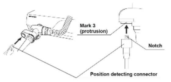
○Connecting the UPD cable to the endoscope
Align the notch on the endoscope plug of the UPD cable with mark 3 on the UPD scope
connector of the endoscope and push the endoscope plug into the UPD scope connector until
it stops (see Figure).
[NOTE]
If force is used on the UPD cable, the endoscope is designed to detach at the endoscope plug,
not at the endoscope connector.
CONFIDENTIAL
43
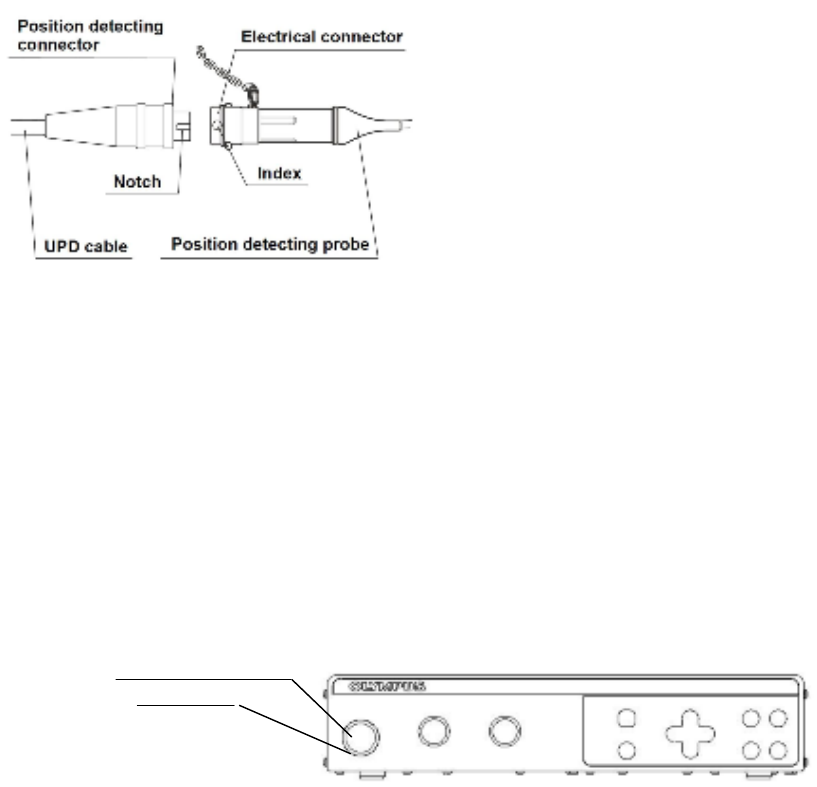
○Connecting the UPD cable to the position detecting probe
1. Holding the electrical connector of the position detecting probe and the connector of the
UPD cable connected to the endoscope position detecting unit, align the index on the
position detecting probe’s electrical connector with the notch on the UPD cable’s position
detecting connector, and connect them (see Figure)..
4.5 Turning power ON
[WARNING]
When two or more endoscope position detecting units are used, do not turn the main units
ON at the same time. Otherwise, the scope model.
Press the power switch to turn ON the endoscope position detecting unit, confirm that the
power indicator on the main unit is lit (see Figure).
Power switch
Power indicator
4.6 Starting the endoscopic examination
1. Confirm the direction in which the endoscope is pointing by checking the viewpoint
indicator arrow. When the viewpoint indicator arrow is selected not to be displayed, press
the “Enter” button to display it.
[NOTE]
CONFIDENTIAL
44
For setting the viewpoint indicator arrow, refer to ○Viewpoint indicator arrow”
2. Start the endoscopic examination as indicated in the instruction manual for the
endoscope in use.
[NOTE]
For the start position of the scope model, refer to Section 4.2, “Scope model display range”
4.7 Displaying the scope model
The scope model is displayed as described below.
• Gray scale: The shape of the endoscope is represented as a gray cylinder. The areas
near the viewpoint are displayed in bright gray and those apart from the viewpoint are
displayed in dark gray.
• Distal end display: The section corresponding to the distal end of the endoscope is
represented by a yellow sphere.
• Colors
Color Function
Gray Stable section
Yellow • Parts of the endoscope that are located outside of the detection area.
• Section where the shape of the scope model is not accurate.
• Section where a stable shape of the scope model cannot be displayed.
Red Parts of the endoscope, parts of the position detecting probe, or the UPD
cable (MAJ-1881) broke down.
Translucent The area from the proximal end of the insertion tube to the start position of
the scope model where the whole insertion tube of the endoscope is within
the left side from the start position of the scope model.
Not displayed • Because the insertion tube of the endoscope is too close or too far from
the coil unit, the coil unit is unable to detect the endoscope.
• The distal end of the endoscope is outside the detection range.
[NOTE]
• The areas displayed in yellow, red, and/or translucent should be regarded as incorrect
because their accuracy is low.
• If the endoscope, the position detecting probe, or UPD cable (MAJ-1881) fails in the
middle of the examination, the scope display area corresponding to the failed section is
displayed in red. When the endoscope position detecting unit is turned OFF and then ON
again, the error message will appear.
• Wavering: The scope model display may waver sometimes. This is not a malfunction.
CONFIDENTIAL
45
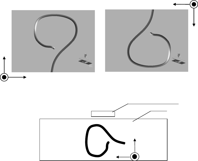
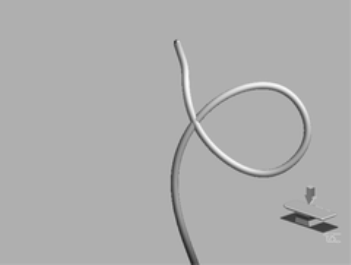
• Fusion: When different sections of the insertion tube of the endoscope come close to each
other, the overlapped areas in the scope model display may be shown as if they are fused
(see Figure).
• Overlapping of intersected sections:
When different sections of the insertion tube of the endoscope become close to each other,
the intersected areas in the scope model display may be shown upside down or in an
inaccurate shape.
[WARNING]
If the insertion tube of the endoscope forms a loop during an examination, and the
overlapped areas in the scope model display may be shown as if they are fused, the
intersected areas may be shown upside down or in an inaccurate shape. In such a case,
dissolve the fusion in the display by moving the endoscope slightly while observing the
scope model display to undo the loop of the insertion tube. It is also possible to correct the
way the overlapped areas of the insertion tube are displayed and then undo the loop if the
current status requires it. If you attempt to undo the loop of the insertion tube by observing
the scope model display while the overlapped areas in it are shown as fused or in an
inaccurate shape, patient injury could result.
Influence of electromagnetic radiation
This instrument which utilizes weak AC magnetic fields is subject to electromagnetic
radiation (noise). To reduce the influence of electromagnetic radiation, this instrument
performs the following:
○Selection of frequencies for use
This instrument automatically selects frequencies of AC magnetic fields for use. After
measuring the noise levels at predetermined three frequencies, this instrument selects a
frequency generating the lowest noise level at powering ON this instrument.
CONFIDENTIAL
46
[NOTE]
Fixing the frequency to use is also possible. See Section 8.2 “System setup”.
○Selection of display speed
Under the environment with high level noise, the scope model will be displayed at lower
speed so that this instrument can get enough signals. After measuring the noise levels, this
instrument selects speed to display the scope model at powering ON.
[NOTE]
- If the scope model display wavers significantly or becomes unstable when operating the
endoscope position detecting unit, the cause may be increased external noise. In that case,
bring the receiver dish to the patient as close as possible. If no improvement is observed,
turn the endoscope position detecting unit OFF and turn it ON again.
- Fixing the display speed is also possible. See Section 8.2 “System setup”.
4.8 Operation at the end of an examination
1. Turn the endoscope position detecting unit and ancillary equipment OFF.
2. Disconnect the UPD cable (MAJ-1881) from the endoscope.
3. Disconnect the hand coil (MAJ-1859) and reference plate (MAJ-1860) from the endoscope
position detecting unit.
[CAUTION]
Be sure to turn the endoscope position detecting unit OFF before connecting or
disconnecting the UPD cable, reference plate, and hand coil to or from the endoscope
position detecting unit. Otherwise, the endoscope, endoscope position detecting unit,
reference plate, and/or hand coil may be damaged.
4. Remove the reference plate cover (MAJ-1880) from the reference plate.
CONFIDENTIAL
47
Chapter 5 Functions
This chapter describes functions of the buttons of main unit and usage of the hand coil and
the reference plate. Before use, refer to the “Function setup” for functions that need to be
set in “System setup” and “User preset”.
5.1 Rotating the scope model
The scope model can be rotated as required.
[WARNING]
Make sure to match the posture of the figure image with that of the patient. Improper
operation due to a mismatch between the posture of the patient, the actual endoscope
position in the patient cavity, and the position displayed on the UPD screen may result in
patient injury and/or perforation.
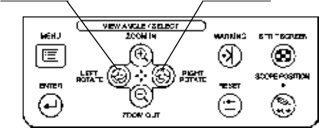
Press the “Rotate left” or “Rotate right” button on the control panel (see Figure). The scope
model will be rotated as shown in Figure.
Rotate left Rotate right
[NOTE]
• After the settings are completed, the setup is held in memory even after the endoscope
position detecting unit is turned OFF. The previous setup will be recalled the next time the
unit is turned ON.
• The rotation angle of the scope model can be saved and recalled as described in “User
preset”
• The viewpoint indicator arrow on the screen shows the direction in which the scope model
is viewed. For showing the arrow, refer to ○Viewpoint indicator arrow”
• Pressing the reset switch recalls the rotation angle that has been saved in the previous
“Saving and recalling the display setup” operation.
• By rotating the scope model, there may be space between the start position of the scope
model and the bottom of the screen.
CONFIDENTIAL
48
• By rotating the scope model, the scope model may be out of the screen. For redisplaying
the scope model, press the reset switch.
5.2 Varying the size of the scope model
The size of the scope model as well as the sizes of the marker and gauge can be varied as
described below.
[NOTE]
• With the initial setup, the zooming ratio is set to the middle ratio.
• After this setup is completed, the settings are held in memory even after the endoscope
position detecting unit is turned OFF. The previous setup will be recalled the next time the
unit is turned ON.
• The zooming ratio of the scope model can be saved and recalled as described in Section
8.3 “User preset.”
• By zooming in the scope model, the scope model may be hidden from view. For
redisplaying the scope model, press the reset switch.
• Pressing the reset switch recalls the zooming ratio that has been saved in the previous “ ”
operation.
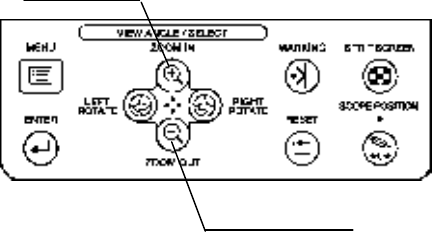
Press the “ZOOM IN” or “ZOOM OUT” button on the control panel (see Figure). The scope
model will be zoomed in or out (i.e., magnified or reduced) as shown in Figure.
ZOOM IN
ZOOM OUT
CONFIDENTIAL
49
5.3 Splitting the screen
The scope model can be displayed on two screens by splitting the screen.
[NOTE]
After this setup is completed, the settings are held in memory even after the endoscope
position detecting unit is turned OFF. The previous setup will be recalled the next time the
unit is turned ON.
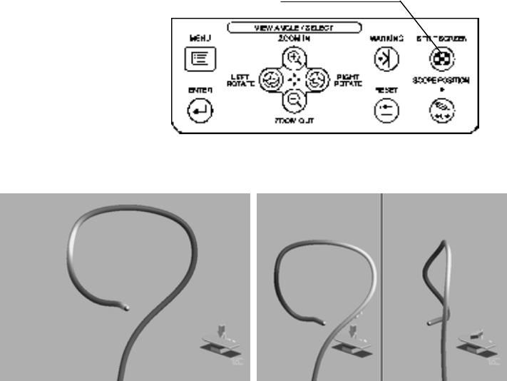
Each press of the split screen button on the control panel changes the split-screen display
and single-screen display alternately (see Figure).
SPLIT SCREEN
Splitting the screen for the operating table image
Single-screen display Split-screen display
[NOTE]
• One screen shows the single screen display and the other shows the single screen view as
well as the 90° rotated view in the split screen.
• The view angles in the right and left sides of the split screen are indicated by the
viewpoint indicator of the operating table image in each screen.
• By pressing the split screen switch, the scope model is redisplayed so that the center of
the top or bottom of the split screen corresponds with the start position of the scope model.
CONFIDENTIAL
50
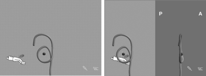
Splitting the screen for the figure image
Single-screen display Split-screen display
[NOTE]
• The screen with the view angle selected from the menu is displayed.
• The view angles on the right and left sides of the split screen are indicated by the A-P
indicator and the figure image respectively.
• By pressing the split screen switch, the scope model is redisplayed so that the center of
the top or bottom of the split screen corresponds
CONFIDENTIAL
51
5.4 Resetting the setup
Pressing the reset switch resets the settings made in the previous “User preset” operation.
When no operations are made in the Section 8.3 “User preset”, the factory default settings
are recalled.
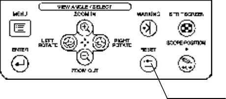
1. Press the reset button (see Figure).
RESET
2. The following settings are reset to the settings made in the previous “User preset”
operation.
• Viewing image selection
• Figure image and view angle (for the figure image selection)
• View indicator arrow (for the figure image selection)
• A-P indicator selection (for the figure image selection)
• Display mode selection
• Scope model thickness setup
• Information display selection
• Rotation angle of scope model (for the operating table image selection) or posture of the
figure image (for the figure image selection)
• Zooming ratio of scope model
[NOTE]
• By pressing the reset switch, the scope model is redisplayed so that the center of the
bottom of the screen corresponds with the start position of the scope model.
CONFIDENTIAL

52
5.5 Connection indicators
When the endoscope or the position detecting probe, reference plate (MAJ-1860), and/or
hand coil (MAJ-1859) are connected, the corresponding connection indicators are displayed.
The color of each connection indicator varies depending on the connection and detection
status.
The endoscope position display shows the scope connection indicator, probe connection
indicator, plate connection indicator, and marker connection indicator in the colors listed in
Table (see Figure).
Item Display Description
Green Normal
Yellow Out of detection area, no accuracy
and/or unstable
Connection status
color
Red Abnormal or failure
CONFIDENTIAL
53
5.6 Bookmark
Markings are put beside the marking gauge according to the points where you want to
mark.
○ Marking
1. Press the “BOOKMARK” button on the control panel when a desired marking point is
found (see Figure).
BOOKMARK
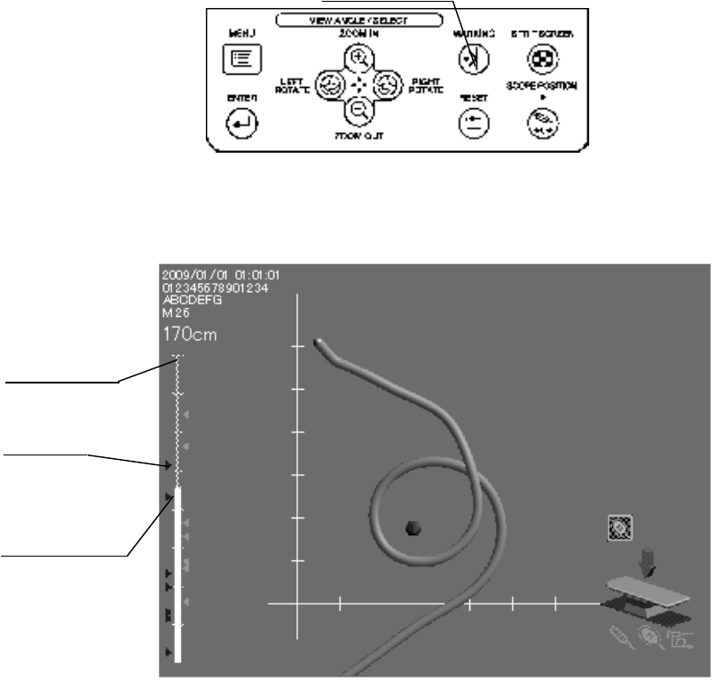
2. A Marking is put beside the marking gauge according to the point where you want to
mark (see Figure).
Marking gauge
Marking
Display length
○Deleting the markings
CONFIDENTIAL
54
1. Press the “BOOKMARK” button on the control panel awhile (see Figure).
2. All markings are deleted.
[NOTE]
•The markings are shown based on the display length. They may not correspond to the
position in the actual intestinal tract.
•Markings can be put every 1 cm.
•Close markings may be shown as one.
•The same position cannot be marked.
•Up to 50 markings can be put beside the marking gauge. The error message will be
displayed when more than 50 markings are marked.
•All markings are deleted automatically under the following cases.
- When the main unit is turned OFF.
- When the UPD cable (MAJ-1881) is disconnected from the endoscope or the position
detecting probe.
5.7 Setting the scope model display range
When the scope model display range is set, the scope model display outside the range will
be erased.
[NOTE]
• After this setup is completed, the settings are held in memory even after the endoscope
position detecting unit is turned OFF. The previous setup will be recalled if the hand coil is
connected the next time the unit is turned ON.
• Even when the unit is turned OFF while the display range is set, the display range setup
is canceled if the hand coil is not connected the next time the unit is turned ON.
• The scope model is redisplayed so that the center of the bottom of the screen corresponds
with the start position of the scope model.
• When the tracking indicator disappears even if the reference plate is connected, the scope
model display range cannot be set.
• The setup of the scope model display range is canceled by disconnecting the hand coil
when the scope model display range is set.
○When using the hand coil (MAJ-1859)
[NOTE]
• When the marker connection indicator is yellow, the scope position switch does not work.
For connecting the hand coil, refer to “Connection of the hand coil (MAJ-1859) .
CONFIDENTIAL
55
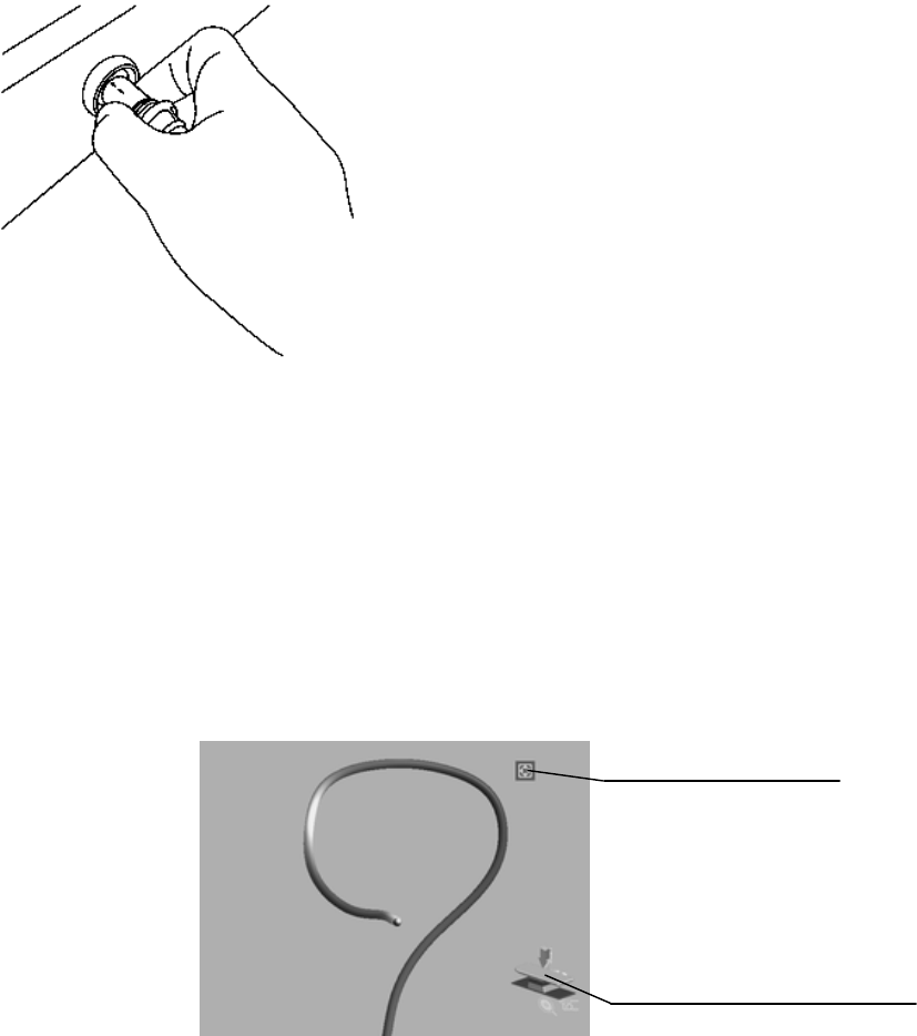
1. Confirm that the marker connection indicator is green, indicating that the hand coil is
available (see Figure).
Marker connection
indicator (Green)
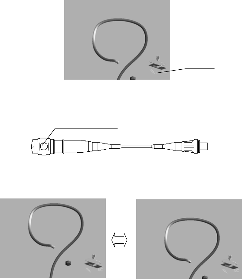
2. Place the hand coil to the position where you want to start the scope model, and then
press the scope position switch on the hand coil (see Figure).
“Scope position” switch
3. The scope model outside the start position is erased the start position is located at the
edge of the screen, and the scope position indicator lights up.
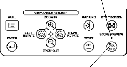
4. Press the scope position switch again or press the scope position button on the control
panel to cancel the setup of the start position of the scope model. The scope position
indicator will be turned off.
○When using the endoscope or the position detecting probe
CONFIDENTIAL
56
1. Place the distal end of the endoscope or the position detecting probe to the position where
you want to start displaying the scope model, and then press the "SCOPE POSITION"
button on the control panel (see Figure).
Scope position indicator
Scope position
2. The scope model outside the start position is erased, the start position is located at the
edge of the screen, and the scope position indicator lights up.
3. Press the scope position button again to cancel the setup of the start position of the scope
model. The scope position indicator will be turned off.
[NOTE]
For the start position of the scope model, refer to Section 4.2, “Scope model display range”.
5.8 Connection of the hand coil (MAJ-1859)
Connect the hand coil when it will be used.
[WARNING]
•Avoid bringing the hand coil or hand coil cover in contact with the skin of the operator
and/or patient. Otherwise, infection of the patient and/or operator may result.
[CAUTION]
•Connect the hand coil to either the main unit or the connection unit (MAJ-Y0093).
Otherwise, it does not operate.
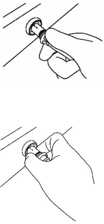
1. Contact the hand coil with its arrow mark on the plug facing upwards with the hand coil
terminal on the main unit (see Figure).
CONFIDENTIAL
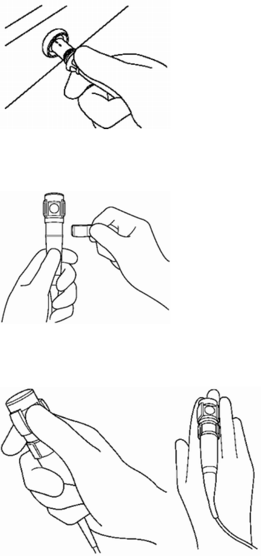
57
2. Hold the plug and insert it straight to the hand coil terminal until it clicks
3. Fit the hand coil cover around the hand coil (see Figure).
4. When the hand coil becomes necessary during examination, the operator should hold it
in his or her hand (see Figure).
[NOTE]
For details on the hand coil function, refer to Section 4.2 “Scope model display range” and
CONFIDENTIAL
58
“Setting the scope model display range”.
5. To disconnect the hand coil, hold the connecting section of the connector and pull it
straight out (see Figure).
5.9 View tracking
When the reference plate (MAJ-1860) is used, the rotation of the scope model is controlled
by the reference plate. When the reference plate is attached to the patient’s body, any
rotation of the patient will accordingly cause a rotation of the scope model (view tracking).
Confirm that the reference plate connection indicator is green. In this condition, the scope
model display changes to the tracking display and the tracking.
Tracking indicator
Plate connection indicator
[NOTE]
•When the tracking indicator disappears while attaching the reference plate to the patient,
the scope model cannot be tracked. In this case, move the patient near the coil unit to
display the tracking indicator.
•For usage of the reference plate, refer to “Connection of the reference plate (MAJ-1860)
CONFIDENTIAL
59
and “Attaching the reference plate (MAJ-1860) to the patient’s body”.
5.10 Connection of the reference plate (MAJ-1860)
Connect the reference plate when the tracking function is required (see Section 5.9, “View
tracking”). Disconnect the reference plate when the tracking function is not required.
[CAUTION]
•Connect the reference plate to either the main unit or the connection unit (MAJ-1928).
Otherwise, it does not operate.
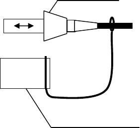
1. Insert the reference plate with its arrow on the connector facing upwards to the reference
plate connector on the main unit (see Figure).
2. Hold the connector and insert it straight to the reference plate connector until it clicks.
3. To disconnect the reference plate, hold the connecting section of the connector and pull it
straight out (see Figure).
CONFIDENTIAL
60
5.11 Attaching the reference plate (MAJ-1860) to the
patient’s body
[WARNING]
• Avoid bringing the reference plate, reference plate cover, and reference plate belt
(MAJ-1029) in contact with the skin of the operator and/or patient. Otherwise, an infection
may result.
[CAUTION]
• Attach the reference plate parallel to the back of the patient and fit the central axis of the
reference plate to the patient’s central axis. Otherwise, the scope model may disappear
during the examination, may not be displayed, or may be incorrectly displayed.
• Attach the reference plate properly to the patient’s body. Otherwise, the scope model will
not be displayed correctly.
− If the reference plate is attached in a manner that the slit contacts the patient’s abdomen,
the scope model display will reverse the left and right.
− If the reference plate is attached so that the cable comes on the side of the patient’s feet,
the scope model display may be shown upside down, or may not be shown at all.
[NOTE]
For details on the reference plate function, refer to the “View tracking”.
○When the reference plate cover (MAJ-1880) is used
[CAUTION]
• Patients with allergies may experience reddening or irritation of the skin caused by the
adhesive on the antenna lead covers.
• Use a reference plate cover before expiration date. Otherwise, the reference plate may not
be securely adhered to the patient’s body. The expiration date of the reference plate cover is
shown on the package.
CONFIDENTIAL
61
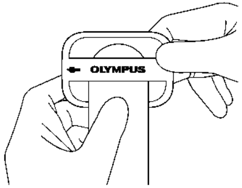
1. Insert the reference plate into the reference plate cover so that the human-shaped index
marking on the reference plate is on the same side as the blue surface of the reference plate
cover (see Figure).
2. Peel off the lining paper from the inside of the reference plate cover (on the blue side),
and adhere the reference plate securely to the reference plate cover (see Figure).
3. Dry the patient’s body by wiping with a dry piece of gauze. If there is too much hair in a
particular location to securely adhere the reference plate cover, shave as necessary.
4. Place the contact surface of the reference plate on the patient’s abdomen so that the cable
comes on the side of the patient’s legs.
5. Remove the lining paper on the back of the reference plate cover by peeling from the
point indicated by the arrow (see Figure), and then press down firmly on the reference
plate to attach it to the patient.
REFERENCE PLATE
blue side
REFERENCE PLAT
E COVER
CONFIDENTIAL
62
[CAUTION]
The reference plate cover used before has lost its adhesiveness. When reattaching the
reference plate, replace the cover with a new one.
○Removing the reference plate cover from the reference plate
1. Remove the reference plate from the reference plate covers. The reference plate cover can
be easily removed by holding the tab and tearing the center section
2. Carefully remove the reference plate cover from the patient.
[CAUTION]
Do not fold or crease the reference plate when removing it from the reference plate cover.
Otherwise, the reference plate may be damaged.
[NOTE]
CONFIDENTIAL
63
The reference plate covers are single-use only.
○When the reference plate cover (MAJ-1880) is not used
1. Pass the reference plate belt through the slit (see Figure).
2. Place the contact surface of the reference plate on the patient’s abdomen and align the
orientation of the patient’s body with that of the human-shaped index marking of the
reference plate so that the cable comes on the side of the patient’s foot.
3. Wrap the reference plate belt around the patient’s body and fasten the reference plate
using the surface fastener on the reference plate belt.
[CAUTION]
• Do not tighten the reference plate belt too much. Excessive tightening can cause patient
pain.
• Attach the reference plate belt firmly around the patient’s body so that the reference
plate will not move. Otherwise, the scope model display will be unstable.
CONFIDENTIAL
64
5.12 Operation using the remote control
The remote control (MAJ-1890) can operate the same function as the control panel does.
[CAUTION]
• Do not use a pointed or hard object to press the keys on the remote control. This may
damage the keys.
•Properly install the remote control. If it is not properly installed, the remote control may
be damaged. Install the remote control on a stable, level surface so that the cable between
the endoscope position detecting unit and remote control is not stretched.
•When operating the remote control, hold the control not the cable. Otherwise, the cable
may break.
•Do not fix the cable using surgical clamps, such as Pean, because the cable may break.
For displaying the scope model, refer to the “Setting the scope model display range”.
[NOTE]
For connecting the remote control, refer to Section 7.7, “Remote control.”.
CONFIDENTIAL
65
Chapter 6 Care, Storage, and Disposal
6.1 Care
If the endoscope position detecting unit and accessories are soiled, perform the following
cleaning procedure immediately after use. If cleaning is delayed, residual organic debris
will begin to solidify, and it may be difficult to effectively clean the endoscope position
detecting unit. The endoscope position detecting unit should also be cleaned routinely.
[WARNING]
After cleaning the main unit and accessories, dry them thoroughly before use. If they are
used while still wet, there is the risk of electric shock.
[CAUTION]
• Do not clean the output connector, the terminals, or the AC power mains inlet. Cleaning
them can deform or corrode the contacts, which could damage the endoscope position
detecting unit.
• Do not autoclave or gas sterilize the endoscope position detecting unit. These methods
will damage it.
• The UPD cable is not waterproof and should not be cleaned together with the endoscope.
Otherwise, the equipment will malfunction.
• Do not wipe the external surface with hard or abrasive material. The surface will be
scratched.
• Alcohol is flammable. Handle with care.
CONFIDENTIAL

66
○Compatible reprocessing methods and chemical agents
Compatibility summary
The instruments shown below are compatible with several methods of reprocessing. For
appropriate reprocessing methods, refer to Table below, the recommendations of your
infection control committee, and all national and local hospital guidelines and policies.
70% ethyl or isopropyl
alcohol
Detergent
solution
Hand coil (MAJ-1859)
Hand coil cover (MAJ-1879)
Reference plate (MAJ-1860)
compatible
not
compatible
[WARNING]
Alcohol is not a sterilant or high-level disinfectant.
○Detergent solution
Use a medical-grade, low-foaming, neutral pH detergent, or enzymatic detergent and follow
the manufacturer’s dilution and temperature recommendations. Contact Olympus for the
names of specific brands that have been tested for compatibility with these instruments. Do
not reuse detergent solutions.
[WARNING]
Excessive detergent foaming can prevent fluid from adequately contacting components.
○Care of the hand coil (MAJ-1859), hand coil cover (MAJ-1879), and
reference plate (MAJ-1860)
1. Turn the endoscope position detecting unit OFF and disconnect the power cord.
2. To remove dust and dirt on the respective accessories, wipe them using a lint-free cloth
moistened with neutral detergent.
3. If the accessories are soiled with patient blood or debris, wipe off all gross debris using
neutral detergent and then decontaminate their surfaces using a lint-free cloth moistened
CONFIDENTIAL
67
with 70% ethyl or isopropyl alcohol or follow the instructions described in Section 6.2
“Cleaning procedures for accessories.
4. Make sure that the accessories are completely dry after wiping.
○Care of the main unit and accessories other than the hand coil
(MAJ-1859), hand coil cover (MAJ-1879), and reference plate
(MAJ-1860)
1. Turn the endoscope position detecting unit OFF and disconnect the power cord.
2. To remove dust and dirt on the main unit and accessories, wipe them using a lint-free
cloth moistened with neutral detergent.
3. If the accessories are soiled with patient blood or debris, wipe off all gross debris using
neutral detergent and then decontaminate their surfaces using a lint-free cloth moistened
with 70% ethyl or isopropyl alcohol.
4. Make sure that the accessories are completely dry after wiping.
6.2 Cleaning procedures for accessories
This section includes the cleaning procedures for the accessories and reprocessing
equipment listed below.
•Hand coil (MAJ-1859)
•Hand coil cover (MAJ-1879)
•Reference plate (MAJ-1860)
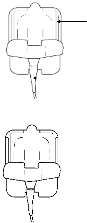
○Attaching the water-resistant cap (MAJ-1899)
[CAUTION]
• The electrical connector of the hand coil or reference plate is not waterproof. Before
immersing the endoscope, always attach the water-resistant cap. Otherwise, equipment
damage may result.
• Always use a dry water-resistant cap. Any water remaining on the water-resistant cap
may cause damage to the equipment.
1. Confirm that the inside of the water-resistant cap is dry and free from debris. If the
inside of the water-resistant cap is wet or there is debris present, wipe with a dry, lint-free
clean cloth.
CONFIDENTIAL
68
Connector
Water-resistant cap
2. Put the water-resistant cap on the connector and turn it clockwise to close.
○Manual cleaning
[CAUTION]
Make sure that the items immersed in detergent solution do not contact one another.
1. Fill a basin with detergent solution at the temperature and concentration recommended
by the detergent manufacturer. Use a basin that is deep enough to allow all equipment to
be completely immersed.
2. Immerse all equipment in the detergent solution. Using a clean, soft brush or lint-free
cloth, meticulously clean all external surfaces in detergent solution.
3. Soak all equipment for the amount of time and at the temperature recommended by the
detergent manufacturer.
4. Remove all equipment from the detergent solution and place it in clean water.
5. Remove all equipment from the clean water.
6. Using a clean, lint-free cloth, thoroughly wipe and dry the external surfaces of all
equipment.
7. Thoroughly wipe all external surfaces using a lint-free cloth moistened with 70% ethyl or
isopropyl alcohol.
8. Make sure that the accessories are completely dry after wiping.
CONFIDENTIAL
69
6.3 Storage
[CAUTION]
Do not store the endoscope position detecting unit in locations exposed to direct sunlight,
X-rays, radioactivity, or strong electromagnetic radiation (e.g., in the vicinity of microwave
therapeutic equipment, MRI, short-wave therapeutic equipment, radio equipment, or
cellular/portable phone).
Damage to the endoscope position detecting unit may result.
1. Turn the endoscope position detecting unit OFF and disconnect the power cord.
2. Disconnect all ancillary equipment connected to the endoscope position detecting unit.
3. Store the equipment at room temperature in the horizontal position in a clean, dry, and
stable location.
CONFIDENTIAL
70
Chapter 7 Installation and Connection
[WARNING]
• Review this chapter thoroughly, and prepare the instruments properly before use. If the
equipment is not properly prepared before each use, equipment damage, patient and
operator injury and/or fire can occur.
• When non-medical electrical ancillary equipment is used, connect its power cord via an
isolation transformer prior to connecting it to this endoscope position detecting unit.
[CAUTION]
•Turn OFF all instruments before connecting them. Otherwise, equipment damage or
malfunction may result.
• Use appropriate cables only. Otherwise, equipment damage or malfunction can result.
• Properly and securely connect all cables. Otherwise, equipment damage or malfunction
can result.
• The cables should not be sharply bent, pulled, twisted or crushed. Cable damage can
result.
• Never apply excessive force to connectors. This could damage the connectors.
• Use this instrument only under the conditions described in “Transportation, storage, and
operation environment” and “Specifications” in the Appendix. Otherwise, improper
performance, compromised safety and/or equipment damage may result.
• When moving the receiver dish stand from one location to another, firmly hold the handle
with one hand and the pole with the other. Otherwise, the stand may topple, which may
result in operator injury or damage of the endoscope position detecting unit.
Prepare this endoscope position detecting unit and compatible equipment (shown in the
“System chart” in the Appendix) before each use. Referring to the instruction manuals of
each system component, install and connect the equipment according to the procedure
described in this chapter.
CONFIDENTIAL

71
7.1 Installation work flow
Please see the installation work flow in Figure below. Follow each step of the work flow
before using the endoscope position detecting unit and the ancillary equipment.
1. Install the endoscope position detecting unit and the ancillary
equipment to the mobile workstation, etc.
→ Section 7.2, “Installation of the equipment”
↓
2. Install the receiver dish.
→ Section 7.3, “Installation of the receiver dish”.
↓
3 Connect the endoscope position detecting unit and the ancillary
equipment to the mobile work station, etc.
→ From Section 7.4, “Connection of the receiver dish” to Section 7.8
“Video system center”.
↓
4. Connect the instruments to the power source.
→ Section 7.9 “Connection to an AC mains power supply”.
↓
5. Set up the system setup.
→ Section 8.2 “System setup”.
↓
6. Set up the user preset.
→Section 8.3 “User preset”.
CONFIDENTIAL
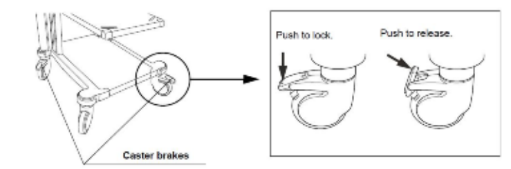
7
2
7.2 Installation of the equipment
[WARNING]
• Keep the ventilation grills of the endoscope position detecting unit clear. The ventilation
grills are located on the side panels. Blockage can cause overheating and equipment
damage.
• Clean and vacuum dust the ventilation grills using a vacuum cleaner. Otherwise, the
endoscope position detecting unit may break down from over heating.
• Place the endoscope position detecting unit on a stable, level surface. Otherwise, the
endoscope position detecting unit may topple down or drop, and user or patient injury may
occur, or equipment damage can result.
• If a trolley other than the mobile workstation (WM-NP1 or WM-WP1) is used, confirm
that the trolley can withstand the weight of the equipment installed on it.
• Do not install the endoscope position detecting unit near a source of strong magnetic
wave (microwave treatment device, short wave treatment device, MRI, radio equipment,
etc.). Otherwise, the endoscope position detecting unit may malfunction.
•Do not fix the cable using surgical clamps, such as Pean, because the cable may break.
•Do not allow the cables to catch operator’s legs. Otherwise, the operator and equipment
may be toppled.
•Connect the cables securely and lock the connectors if they have locks. Otherwise, the
equipment may not operate correctly.
○ Installation on the mobile workstation (WM-NP1, WM-WP1)
1. Place the mobile workstation on a level and flat floor. Lock the caster brakes by pushing
them down (see Figure).
2. Install the mobile shelf of the mobile workstation according to the configuration of the
equipment installed on it as described in the mobile workstation's instruction manual.
3. Place the endoscope position detecting unit on the mobile shelf of the mobile workstation.
CONFIDENTIAL

73
○ Installation in another location
When the equipment is installed in the location other than in the mobile workstation, put it
in the level position.
7.3 Installation of the receiver dish
○How to assemble the receiver dish stand
[CAUTION]
•The weight is very heavy. Be careful not to drop it while assembling the stand. Otherwise, user
injury may result.
•Assemble the receiver dish stand on a level and flat floor. Otherwise, the receiver dish stand
may topple, which may result in user injury or damage of the stand.
1. Insert the end of the pole with a screw hole into the hole of the base (see Figure).
The pole is inserted.
CONFIDENTIAL
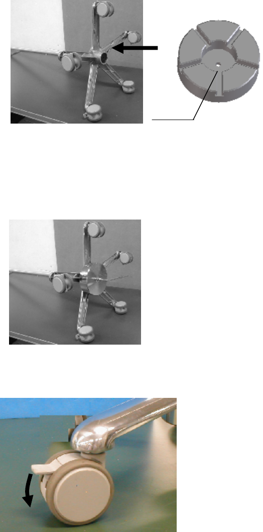
74
2. Lay down the assembled pole and the base gently on the floor. Attach the weight to the base
so that the grooves of the weight fit the base (see Figure)
[CAUTION]
•Be sure to attach the weight to the base. Otherwise, the stand may topple.
3. Tighten the weight, the base, and the pole together with an M8 x 50screw. The screw must be
tightened firmly so that the pole and the base do not wobble (see Figure).
4. Lift up the pole and the base and lock the casters. Two casters have locking mechanism (see
Figure).
Groove
CONFIDENTIAL

75
5. Attach the handle to the pole with an M5×40 screw. There are two holes on the pole. Use the
hole on the side where the protrusions for the cable pocket are located (see Figure).
6. Put the handle cover on the top end of the pole and slide it down to the handle so as to cover
the mounting part of the handle to the pole (see Figure).
Mounting part of the handle to the pole
CONFIDENTIAL
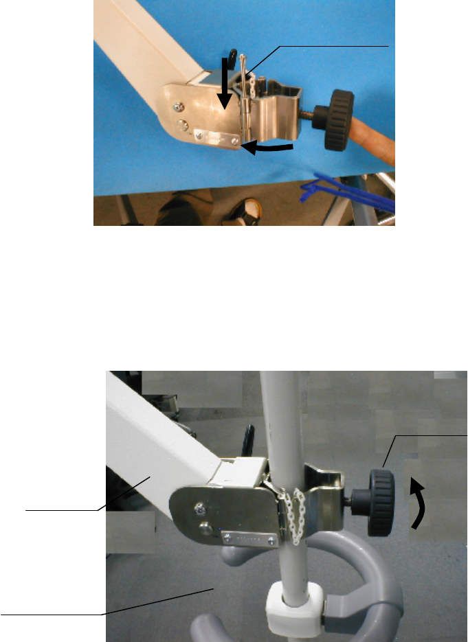
76
7. Close the hinge of the arm and insert a pin into a hole of the hinge (see Figure).
8. Put the mounting part of the arm on the top end of the pole and slide it down to any
appropriate position. Turn the knob to fix the arm after setting the arm so that the arm will stay
within the range of the opening area of the handle.
Loosening the knob completely causes the knob to be detached from the arm and the internal
part of the knob to drop off. Tighten the knob to the necessary extent (see Figure).
Pin
Close
Opening area
of the handle
Arm
Knob
CONFIDENTIAL
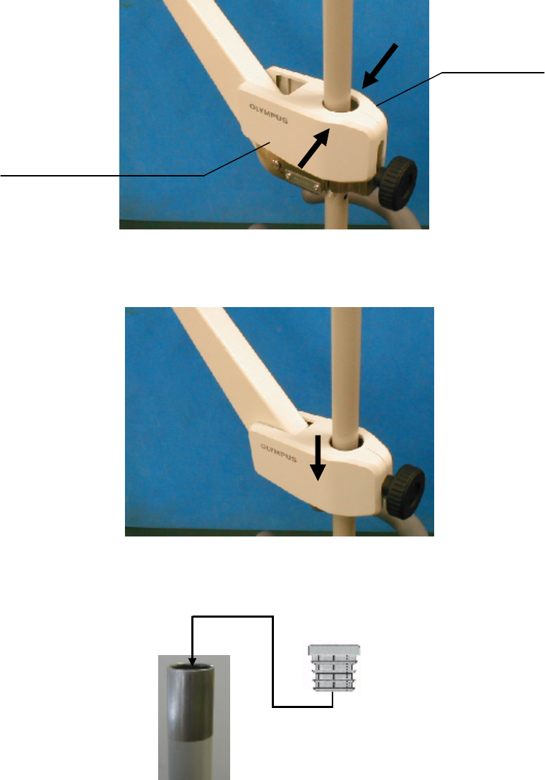
77
9. Sandwich the pole with the arm covers right and left. The grooves on the inner faces of the
arm covers right and left must be engaged (see Figure).
10. Push down the arm cover to a position at which the arm cover completely covers the
mounting part of the hinge (see Figure).
11. Place a cap in the hole of the top end of the pole (see Figure).
Arm cover left
Arm cover right
CONFIDENTIAL
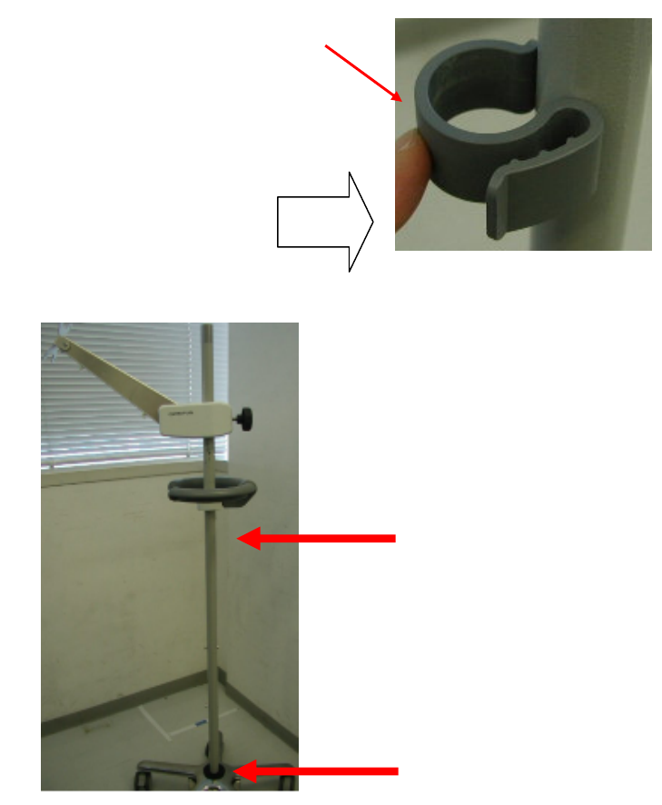
78
12. Attach two cable holders to two locations on the pole shown with the red arrows in the
Figure (see Figure).
Cable holder (Two)
Attach to the pole in the
direction shown with the arrow.
Attach the cable holder here
Attach the cable holder here
CONFIDENTIAL
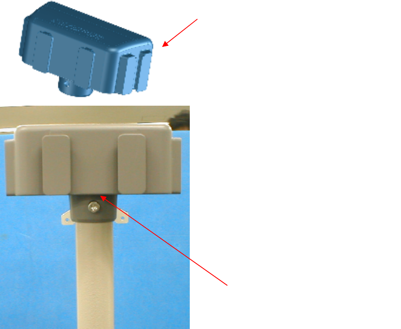
79
○Installation of the holder for hc-rp and the remote control holder onto the receiver dish stand
The holder for hc-rp can hold the hand coil (MAJ-1859) and the reference plate (MAJ-1860).The
remote control holder can hold the remote control (NAJ-1890). The holder hc-rp and the remote
control holder are included in the receiver dish stand supplementary set (MAJ-1978).
[NOTE]
The holder for hc-rp and the remote control holder are optional.
1. Install the holder attachment onto the top of the pole (see Figure). If the cap is attached to the
top of the pole, remove it before installing the holder for hc-rp.
Holder attachment
Fix with the screw included in the
supplementary set
The
Holder attachment is installed.
CONFIDENTIAL
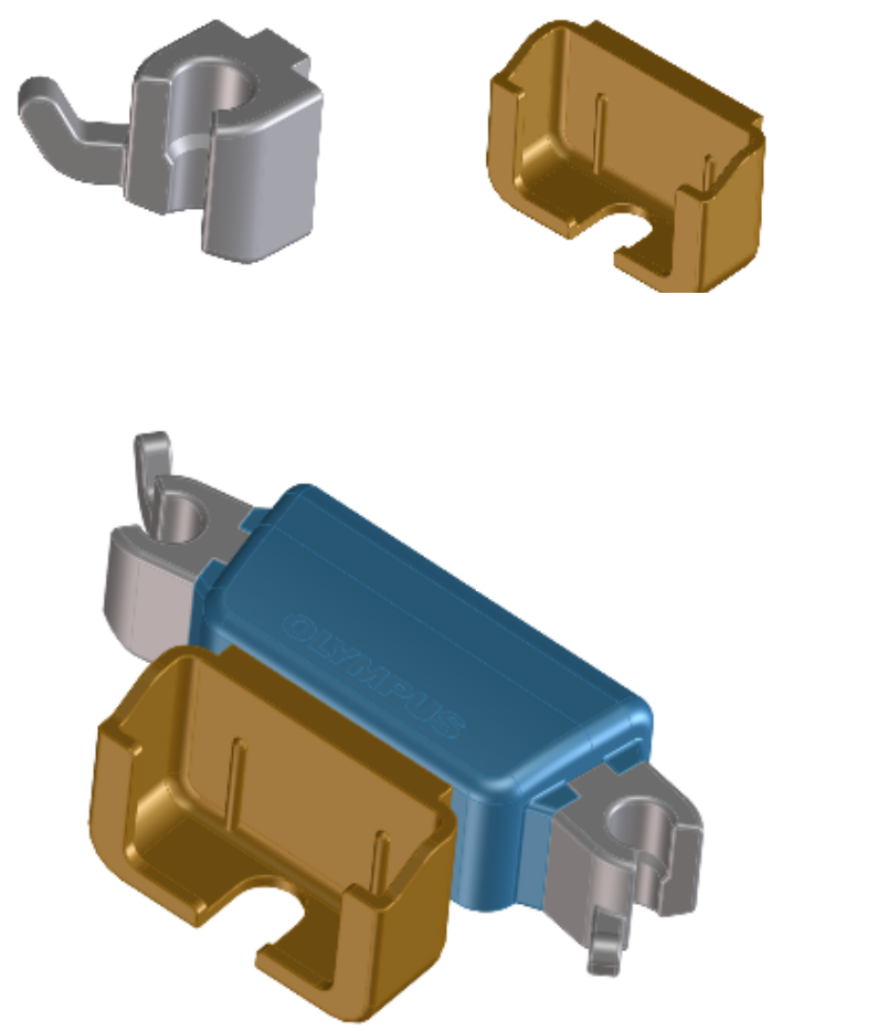
80
2. Attach the remote control holder and two MP holders to the holder mount (see Figure).
○Installation of the receiver dish (MAJ-1868)
Install the receiver dish (MAJ-1868) to the receiver dish stand (MAJ-1907). For installation of the
receiver dish to any other stand, contact Olympus.
1. Install the receiver dish to the receiver dish stand using the four screw holes on the back of
the receiver dish as shown in the Figure.
MP Holders (two)
Remote control holder
The MP holders attached to the holder
atta
chment
.
CONFIDENTIAL

81
Install the receiver dish so that the blue line is on the top.
Four screws
Use the screws packaged with the
receiver dish arm.
Four screw holes on the back of
the receiver dish
CONFIDENTIAL
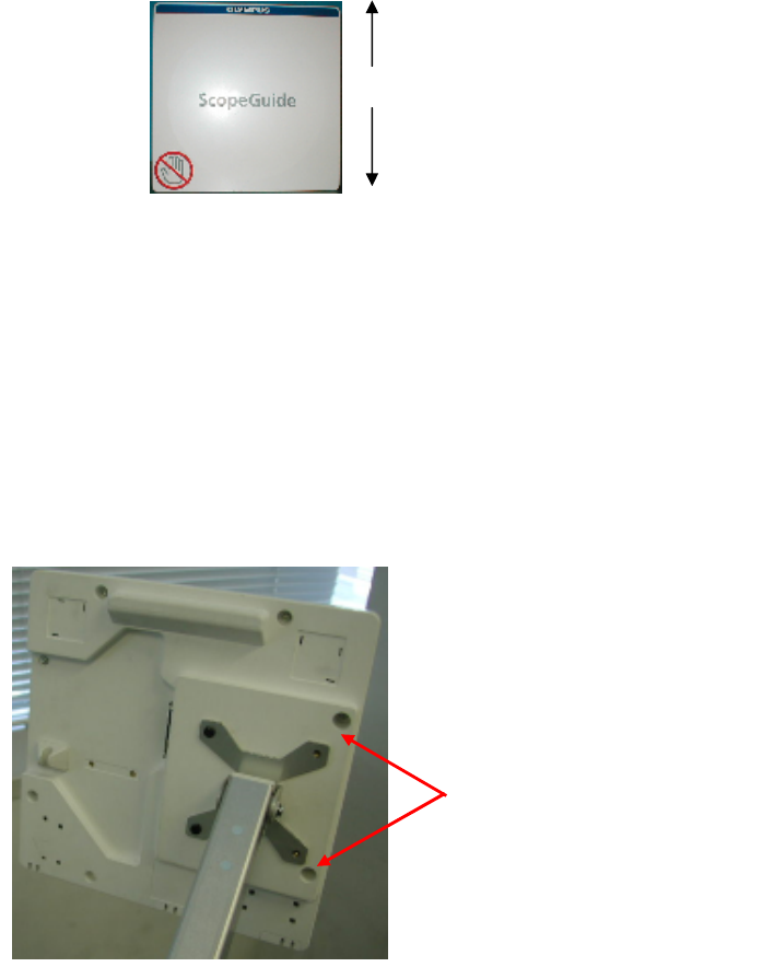
82
○ Installation of the holder to the receiver dish
The holder can hold the hand coil (MAJ-1859). The holder and the M plate are included in the
receiver dish stand supplementary set (MAJ-1978).
[NOTE]
The holder and the M plate are optional.
1. Remove the two screws out of the four which are fixing the receiver dish (MAJ-1868) as
shown in Figure (see Figure).
Remove two screws
Top
Bottom
CONFIDENTIAL

83
2. Install the M plate as shown in the figure. Then attach the holder to the M plate (see Figure).
○Installation of the cable pocket
The cable pocket is included in the receiver dish stand supplementary set (MAJ-1978).
[NOTE]
The cable pocket is optional.
The M plate is installed.
Tighten the
screws again
The MP holder is attached
MP holder
CONFIDENTIAL
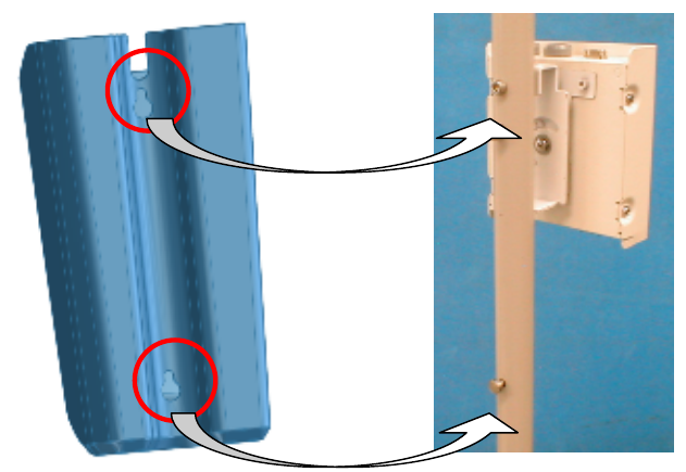
84
1. Attach the cable pocket to the pole of the receiver dish stand so that the two projections on
the pole stay in the two holes of the cable pocket.
○Installation of the holder for hc-rp (MAJ-1938) to the mobile workstation
The holder for hc-rp can hold the hand coil (MAJ-1859) or the reference plate (MAJ-1860).
The holder for hc-rp can be installed to the following mobile workstations
WM-P1 and WM-260* series
[NOTE]
The holder for hc-rp (MAJ-1938) is optional.
* This product may not be available in some areas.
CONFIDENTIAL
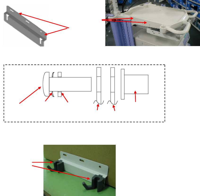
85
1. Install the plate to the top tray of the mobile workstation. Install the screw, washers and nut in
the order shown in Figure.
1. Install two holders onto the plate (see Figure).
7.4 Connection of the receiver dish
1. Check that no video monitor, PC monitor, or a large metallic object is near the receiver
dish. Keep a distance of at least 30 cm between the video monitor, PC monitor, or metallic
object and the receiver dish.
[CAUTION]
Screw
Wave washer Flat washer
Plate Mobile workstation
Nut
Use these
screw holes
Plate Top tray
Holder
Two holders are installed.
CONFIDENTIAL

86
• If a video monitor or PC monitor is located near the coil unit of the endoscope position
detecting unit, the scope model display may be distorted or deformed due to strong
magnetic fields produced by the monitor.
• If a metallic object is located near the coil unit of the endoscope position detecting unit,
the scope model display may also be distorted or deformed.
• In some cases, the material and/or structure of the operating table may cause distortion
or deformation of the scope model display.
[NOTE]
If you have any questions or problems with the installation location of the endoscope
positioning detecting unit or the material and/or structure of the operating table in use,
contact Olympus.
2. For connecting the receiver dish to the endoscope position detecting unit, use the cable
listed below.
Model Product name Note
MAJ-1875 Receiver dish cable 7m
RECEIVER DISH UPD-3
MAJ-1868
Connector
MAJ-1875
7.5 Video equipment
[NOTE]
See the instruction manual for the video equipment to be used.
CONFIDENTIAL
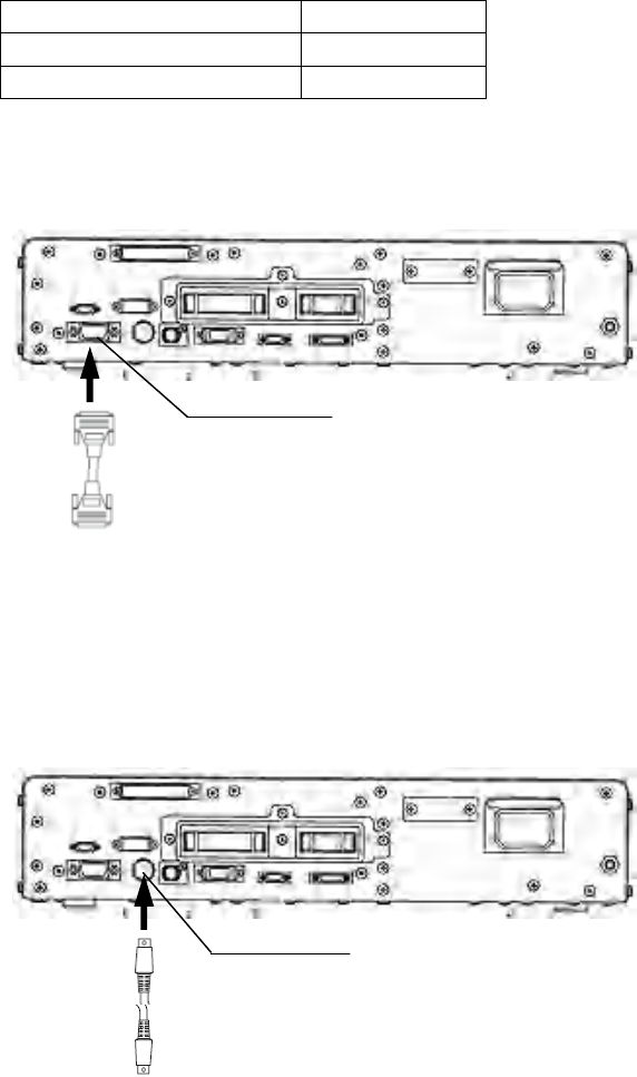
87
○When the XGA monitor is used
The recommended XGA monitor is shown in the Table
Model Product name
ET1528L-7CWM-1-BG-G touch monitor
PLT210-W0X LCD monitor
The video cable for the personal computer (VGA) on the market is used.
UPD-3
XGA OUT
Video cable for the personal computer (VGA) on the market
To the XGA monitor’s input
○When the video equipment with Y/C input is used
The video cable for the Y/C on the market is used.
UPD-3
Y/C OUT
Video cable for the Y/C on the market
To the video equipment’s input
CONFIDENTIAL
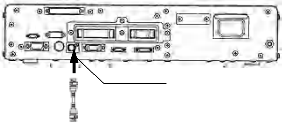
88
○When the video equipment with SDI input is used
For connecting the SDI video equipment to the endoscope position detecting unit, use the
cable listed below.
Table
Model Product name Note
MAJ-1464 SDI cable 22m
UPD-3
MAJ-1464
SDI OUT
To the video equipment’s input
7.6 UPD cable
[WARNING]
Do not place the UPD cable on the operating table. This could result in an infection when
the patient contacts the UPD cable. Also, the scope model display may become distorted or
deformed.
[CAUTION]
• Always turn the endoscope position detecting unit OFF before connecting or
disconnecting the UPD cable. Otherwise, equipment damage or malfunction may result.
• Do not apply excessive force to the UPD cable; it may cause equipment damage.
• Do not immerse the UPD cable in liquids or allow it to become wet; it may cause
equipment damage or malfunction.
• Do not touch the electrical contacts inside the endoscope position detecting unit’s
connectors; it may cause equipment damage or malfunction.
Use the cable shown in Table
Table
Model Product name Note
MAJ-1881 UPD cable
CONFIDENTIAL

89
7.7 Remote control
[WARNING]
•Install the remote control on a stable, level surface so that the cable between the
endoscope position detecting unit and remote control is not stretched. Otherwise, the
remote control may slip or fall and result in patient/operator injury or damage to the
equipment.
The following remote control shown in Table is available.
Table
Model Product name Note
MAJ-1890 Remote control
REMOTE CONTROL UPD-3
MAJ-1890
7.8 Video system center
[NOTE]
See the instruction manual for the video system center.
When connecting the video system center to the position detecting unit, the following
patient data displayed on the video system center can be output to the position detecting
unit.
• ID number
• Patient’s name
• Sex and Age
• Date of birth
CONFIDENTIAL
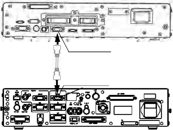
90
○ For CV-180
[CAUTION]
When displaying the image of the position detecting unit (UPD-3) using the PinP function
of the CV-180, use the high definition LCD monitor. Otherwise, the scope model may not be
displayed clearly
For connecting the video system center to the endoscope position detecting unit, use the
cable listed below.
Table
Model Product name Note
MAJ-604 Data transfer cable
UPD-3
CV REMOTE
MAJ-604
PC REMOTE CV-180
○ For CV-260SL/260 *
For connecting the video system center to the endoscope position detecting unit, use the
cable listed below.
Model Product name Note
MAJ-1260* Data transfer cable
CONFIDENTIAL
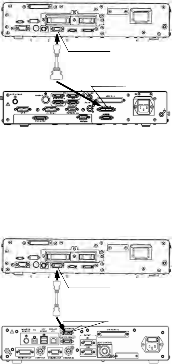
91
UPD-3
CV REMOTE
MAJ-1260*
OPTION B CV-260SL/260
* These Products may not be available in some areas.
○ For CV-160
For connecting the video system center to the endoscope position detecting unit, use the
cable listed below.
Model Product name Note
MAJ-604 Data transfer cable
UPD-3
CV REMOTE
MAJ-604
D.FILE REMOTE CV-160
○ For CV-240 *
For connecting the video system center to the endoscope position detecting unit, use the
CONFIDENTIAL
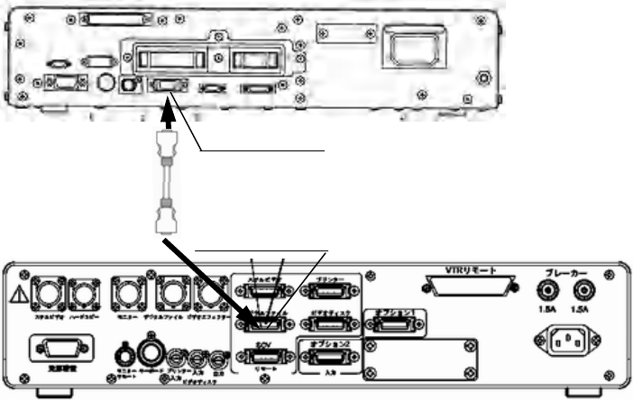
92
cable listed below.
Model Product name Note
MAJ-604 Data transfer cable
UPD-3
CV REMOTE
MAJ-604
DGTL FILE CV-240
* This product may not be available in some areas.
CONFIDENTIAL
93
7.9 Connection to an AC mains power supply
[DANGER]
• Be sure to connect the power plug of the power cord directly to a grounded wall mains
outlet. If the endoscope position detecting unit is not grounded properly, it can cause an
electric shock and/or fire.
• Do not connect the power plug to the 2-pole power circuit with a 3-pole to 2-pole adapter.
It can prevent proper grounding and cause an electric shock.
[WARNING]
• Always keep the power plug dry. A wet power plug may cause electric shocks.
• Confirm that the hospital-grade wall mains outlet to which this instrument is connected
has adequate electrical capacity that is larger than the total power consumption of all
connected equipment. If the capacity is insufficient, fire can result or circuit breaker may
trip and turn OFF this instrument and all other equipment connected to the same power
circuit.
• When using the mobile workstation (WM-NP1, WM-WP1), confirm that the mobile
workstation has adequate electrical capacity that is larger than the total power
consumption of all connected equipment. If the capacity is insufficient, drop in the supply
voltage can result or the electric protective device may trip and turn OFF all the equipment
connected to the mobile workstation.
• When non-medical ancillary electrical equipment is used, always connect the equipment
to a wall mains outlet via an isolation transformer. Otherwise, electric shock can result.
• The total power consumption of all connected equipment to the isolation transformer
should not exceed the rating of the isolation transformer. If it exceeds, add another
isolation transformer. Otherwise, the equipment may not work correctly.
• Do not bend, pull or twist the power cord. Equipment damage including separation of the
power plug and disconnection of the cord wire as well as fire or electric shock can result.
• Be sure to connect the power plug securely to prevent erroneous unplugging during use.
Otherwise, the equipment will not function.
• Do not extend a single wall mains outlet into multiple outlets for connecting the power
cords of both the electrosurgical unit and light source. Otherwise, malfunction of the
equipment may result.
○When the mobile workstation (WM-NP1, WM-WP1) is used
1. Confirm that the endoscope position detecting unit is OFF.
2. Connect the power cord provided with the mobile workstation to the AC power inlet of
the endoscope position detecting unit and the AC mains outlet of the mobile workstation
(see Figure)
CONFIDENTIAL

94
3. Connect the power cords provided with the mobile workstation to the AC power inlets of
the ancillary equipment and the AC mains outlets of the mobile workstation.
4. Connect the power cord of the mobile workstation to the wall mains outlet.
○When a mobile workstation other than the WM-NP1 and
WM-WP1 is used or when no mobile workstation is used
1. Confirm that the endoscope position detecting unit is OFF.
2. Connect the power cord provided with the endoscope position detecting unit first to its
AC power inlet, then to the wall mains outlet.
3. Connect the instruments listed in the following table to the wall mains outlet.
4. Connect the instruments listed in the following table to the isolation transformer.
5. Connect the power cord of the isolation transformer to the wall mains outlet.
○When the mobile workstation (WM-NP1、WM-WP1) is not used
The devices to be connected directly to the wall mains outlet
Model Product name
OEV monitors Monitor
CONFIDENTIAL

95
(OEV143, OEV203, OEV181H, OEV191, OEV191H, OEV261H)
OEP printers Video printer
The devices to be connected to the isolation transformer
Model Product name
VTR VTR
Other than OEV video
monitors Video monitor
Other than OEP video
printers Video printer
CONFIDENTIAL
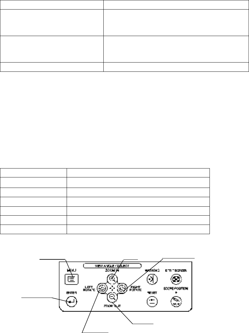
96
Chapter 8 Function setup
The following settings are set to use the position detecting unit and equipment connected to
the position detecting unit properly.
Setting menu Description
System setup Sets the basic functions of the position detecting
unit. For details on the functions, refer to “system
setup”.
User preset Sets the functions used during the examination.
For details on the functions, refer to “User
preset”.
Adjustment Adjusts the scope display. For details, refer to “ ” .
[NOTE]
The functions can be set even if the endoscope or the position detecting probe is not
connected to the position detecting unit.
8.1 Basic operation of the menu
Buttons in the menu
For the buttons and their functions, see Table below.
Button Function
ROTATE LEFT Moves the cursor to the left.
ROTATE RIGHT Moves the cursor to the right.
ZOOM IN Moves the cursor up.
ZOOM OUT Moves the cursor down.
ENTER Determines the category selected by the cursor.
MENU Displays or closes the window.
ROTATE
MENU ZOOM IN RIGHT
ENTER
ROTATE ZOOM OUT
LEFT
CONFIDENTIAL
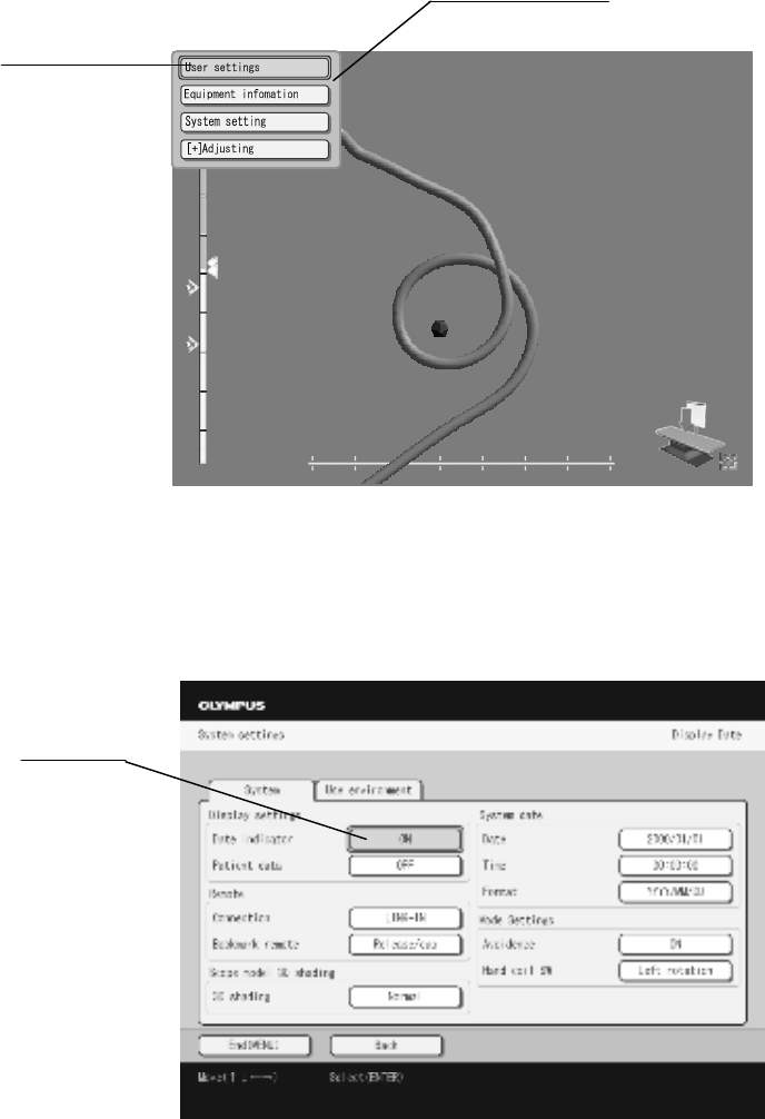
97
1. Press the “MENU” button on the control panel to display the menu list on the scope
model display (see Figure).
Menu list
Cursor
2. Move the cursor on the setting item and press the “ENTER” button to display the setting
window (see Figure).
Cursor
CONFIDENTIAL
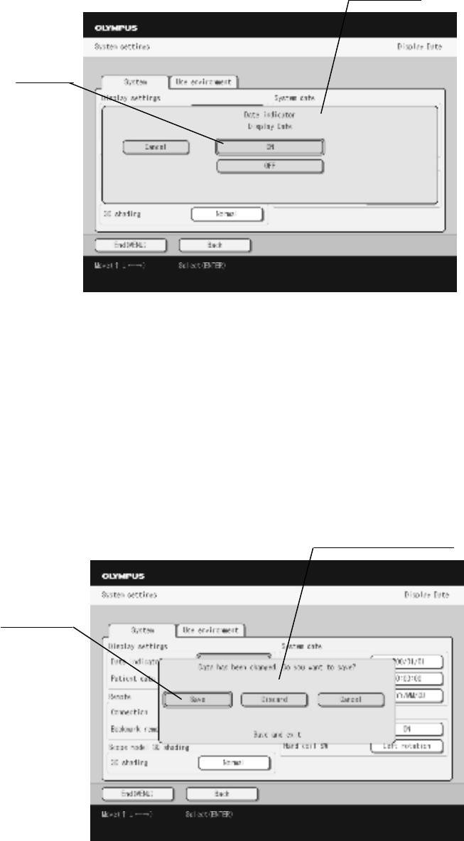
98
3. Move the cursor on the setting item in the setting window and press the “ENTER”
button to display the window of the selected setting item (see Figure).
Window
Cursor
4. Move the cursor to select the setting.
5. Press the “ENTER” button to change the setting, and the window exits; select the
“CANCEL” button and press the “ENTER” button to keep the setting, and the window
exits.
6. Select the “Back” button and press the “Enter” button to return to the upper level.
7. After all settings are completed, select the “Exit” and press the “ENTER” button. When
any settings are changed, the confirmation window is displayed. For details on operations
here, refer to Table.
Confirmation window
Cursor
CONFIDENTIAL

99
Selection
Description
Yes Changes settings and exits from the menu.
No Not change settings and exits from the menu.
Cancel Returns the menu window to continue to change the settings.
8.2 System setup
Set various settings, such as the display setting and system date.
Settings of the display
○Date and time display
1. Set the display of date and time in the scope model display.
Setting value Description
ON Displays the current date and time in the scope model display.
OFF Not display the current date and time in the scope model display.
○Patient data display
1. Set the display of patient data in the scope model display.
Setting value Description
ON Displays the patient data in the scope model display.
OFF Not display the patient data in the scope model display.
[NOTE]
The patient data is displayed when the video system center is connected to the position
detecting unit.
Settings of the miscellanea
○Frequency of transmitting
CONFIDENTIAL
100
1. Set the frequency for detecting the scope model.
Setting value Description
Automatic Automatically selects the frequency for detecting the scope model from
“f1” to “f4”.
f1 Use the frequency set in the "f1”.
f2 Use the frequency set in the "f2”.
f3 Use the frequency set in the "f3”.
f4 Use the frequency set in the "f4”.
[CAUTION]
Do not change this setting in ordinary cases. Otherwise, the scope model display may be
distorted or deformed.
○Fusion avoidance function
1. Set the fusion avoidance function.
Setting value Description
ON Activate the fusion avoidance function.
OFF Inactivate the fusion avoidance function.
[CAUTION]
Do not change this setting in ordinary cases. Otherwise, the scope model display may be
distorted or deformed.
○Marking remote
This function is the future extension; it is not used currently.
○
Model shading
1. Enhance the contrast of the shading of the scope model
Setting value Description
Standard No enhancement is made to the shading contrast of the scope model
Enhancement Enhances the shading contrast of the scope model
CONFIDENTIAL

101
Date and time of the system
○Date
Set the current date.
1. Move the cursor on the year, month, or date and press the “ZOOM IN” or “ZOOM OUT”
button to change the numerical value (see Figure).
Year Month Date
○Time
Set the current time.
1. Move the cursor on the hour, minute, or second and press the “ZOOM IN” or “ZOOM
OUT” button to change the numerical value (see Figure).
Hour Minute Second
CONFIDENTIAL

102
○Display format
1. Set the date display format.
Date display format Description
• MM/DD/YYYY • MM-DD-YYYY • MM.DD.YYYY
• MM DD YYYY • DD/MM/YYYY • DD-MM-YYYY
• DD.MM.YYYY • DD MM YYYY • YYYY/MM/DD
• YYYY-MM-DD • YYYY.MM.DD • YYYY MM DD
YYYY:Year
MM:Month
DD:Date
○
Hand coil switch
1. Set the functions to be assigned to the remote switch of the hand coil.
Setting value Description
Scope position Sets the scope position
ROTATE LEFT Rotates the scope model in the left direction
Split screen Changes the screen between the split-screen and the single-screen
○
Display speed
1. Set the display speed of the scope model.
Setting value Description
Automatic Displays the scope model at high or medium speed depending on
the external noise of this instrument
Low Displays the scope model at low speed
Medium Displays the scope model at medium speed
High Displays the scope model at high speed
[CAUTION]
Do not change this setting in ordinary cases. Otherwise, the scope model display may be
unstable.
[NOTE]
- When the Automatic is selected, the Medium speed mode to display the scope model is
CONFIDENTIAL

103
disabled.
- For details of the automatic change of the display speed, see Section 4.7 “Displaying the
scope model”.
Connection of the video system center
○Connecting terminal
1. Set the communication mode with the video system center.
Setting value Description
Communication A A communication mode using the “LINK IN" connector.
This is a future extension.
Communication B A communication mode using the “CV REMOTE”
connector.
8.3 User preset
Each function can be set by user or endoscope. Up to 20 presets of the display can be saved.
○Basic operation of the user preset
1. Display the “User preset” window, move the cursor on the “Call” or “Edit” in the window,
and press the “ENTER” button on the control panel.
CONFIDENTIAL
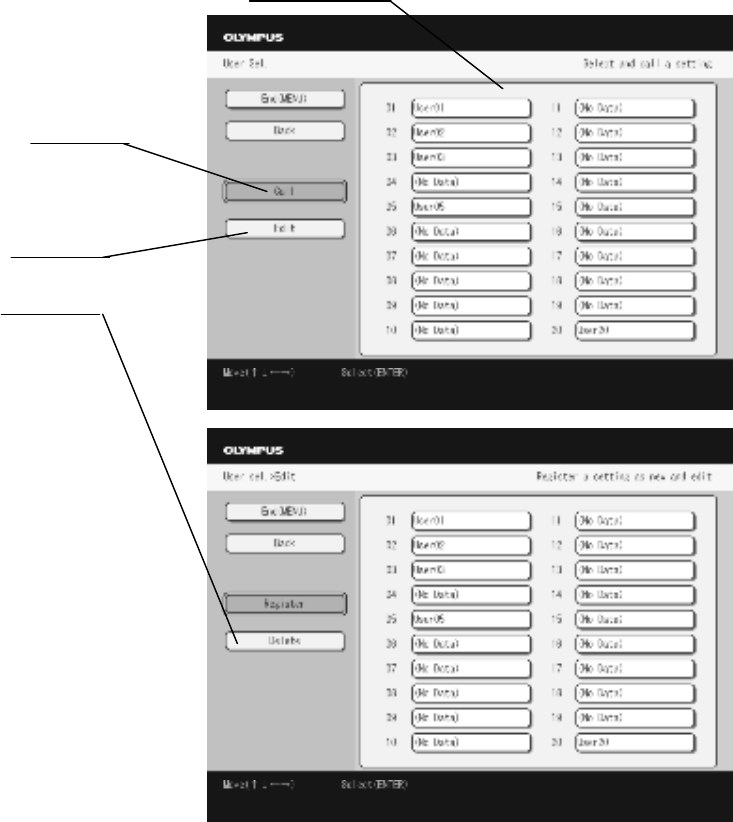
104
User list
Call
Edit
Delete
Operation Function
Select Recalls the desired setup to set each function.
Edit Edit the desired user preset data.
Delete Deletes the data of selected user.
Edit Sets the new user preset, and edits and/or deletes the data of the selected user.
2. When selecting the “Edit” button and pressing the “Enter” button, “Register“ button and
“Delete” button will be displayed.
○Setting the new user preset
CONFIDENTIAL
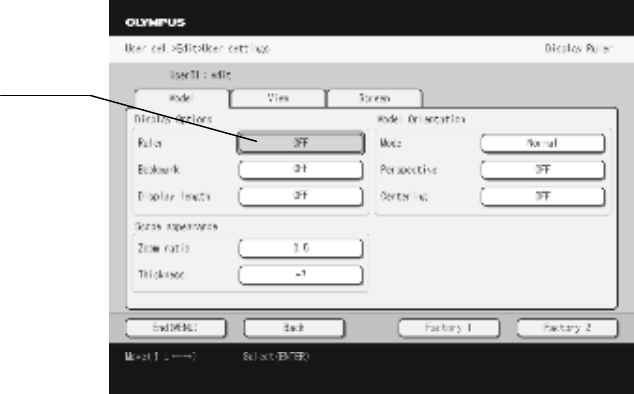
105
1. Move the cursor on the “New” in the User preset window and press the “ENTER” button
on the control panel.
2. The setting window for setting each category is displayed (see Figure). For each setting,
refer to the following instructions.
Cursor
[NOTE]
•Each preset data is saved in the user list in order (from No.1 to No.20). The number is
suffixed on each user’s name.
•When the user list is full, a new preset data cannot be saved. Delete the unnecessary data
to save the new data.
CONFIDENTIAL
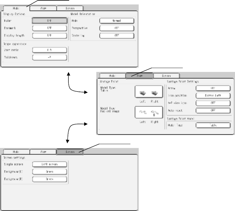
106
3. Move the cursor on the “Tab” and press the “ROTATE LEFT” or “ROTATE RIGHT” button to
change the setting page.
Tab
Tab
Change the page by pressing
the “ROTATE LEFT” or
“ROTATE RIGHT” button
Tab
○Selecting the user preset
1. Move the cursor on the “Select” in the user preset window and press the “ENTER” button
on the control panel.
CONFIDENTIAL

107
2. Move the cursor on a desired user’s name to recall and press the “ENTER” button on the
control panel (see Figure).
User list
Cursor
Select
3. The selected preset is called, and the scope model display is returned.
[NOTE]
The list of the user preset currently called is displayed in violet.
○Editing the user preset
1. Move the cursor on the “Edit” in the user preset window and press the “ENTER” button.
2. Move the cursor on the desired user’s name to edit and press the “ENTER" button (see
Figure).
User list
Cursor
Edit
CONFIDENTIAL
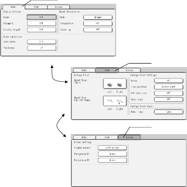
108
3. The setting window for setting each category is displayed. For each setting, refer to the
following instructions.
4. Move the cursor on the “Tab” and press the “ROTATE LEFT” or “ROTATE RIGHT”
button to change the setting page (see Figure).
Tab
Tab
Change the page by
pressing the “ROTATE LEFT” or
“ROTATE RIGHT” button
Tab
○Deleting the user preset
1. Move the cursor on the “Delete” in the user preset window and press the “ENTER”
button.
CONFIDENTIAL
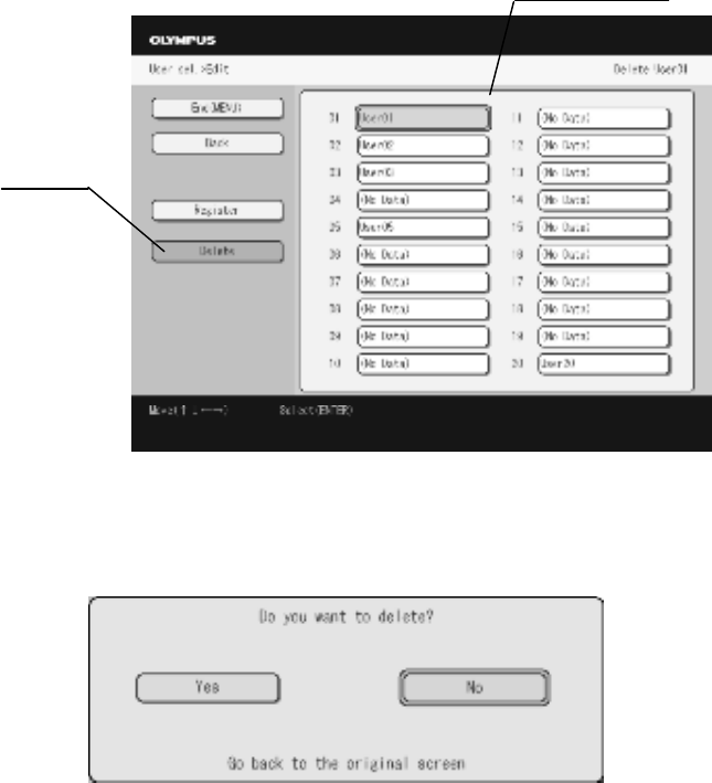
109
2. Move the cursor on the desired user’s name to delete and press the “ENTER" button (see
Figure).
User list
Delete
3. The confirmation window is displays (see Figure). When deleting the preset, move the
cursor on the “Yes” and press the “ENTER” button.
Information display
○Displaying the gauge
1. Set the display of gauge in the scope model display.
Setting value Description
ON Displays the gauge in the scope model display.
OFF Not display the gauge in the scope model display.
CONFIDENTIAL
110
○Displaying the marking
1. Set the display of marking in the scope model display.
Setting value Description
ON Displays the marking in the scope model display.
OFF Not display the marking in the scope model display.
○
Displaying the display length
1. Set the display of the display length in the scope model display
Setting Value Description
ON Displays the display length in the scope model display.
OFF Not display the display length in the scope model display.
Scope model
○Zooming ratio
1. Set the zooming ratio of the scope model. The ratio can be changed from 0.5 to 3.0 times
in steps of 0.1 times.
[NOTE]
• For zooming in or out the scope model, refer to Section 5.2, “Varying the size of the scope
model”.
• Pressing the “Reset” button or selecting the desired user preset recalls the zooming ratio
that has been saved in the user preset operation.
○Scope model thickness
1. Adjust the scope model thickness from -7 to +7.
Display mode
CONFIDENTIAL
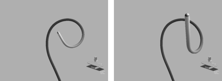
111
○Changing the display mode
1. Set the viewing direction of the scope model.
Setting value Description
From the top Displays the scope model from the top to the bottom in the screen.
From the bottom Displays the scope model from the bottom to the top in the screen.
[NOTE]
For displaying the scope model and its actual position, refer to the Section 4.2, “Scope
model display range”.
○Changing the perspective
1. Set the perspective of the scope model.
Setting value Description
ON The perspective of the scope model is enabled.
OFF The perspective of the scope model is disabled.
Perspective OFF Perspective ON
○Start position of the scope model
1. Set the start position of the scope model.
Setting value Description
ON The center of the bottom of the monitor display corresponds to the start position of
the scope model. When the display mode is set to “From the top”, the center of the top of the
CONFIDENTIAL
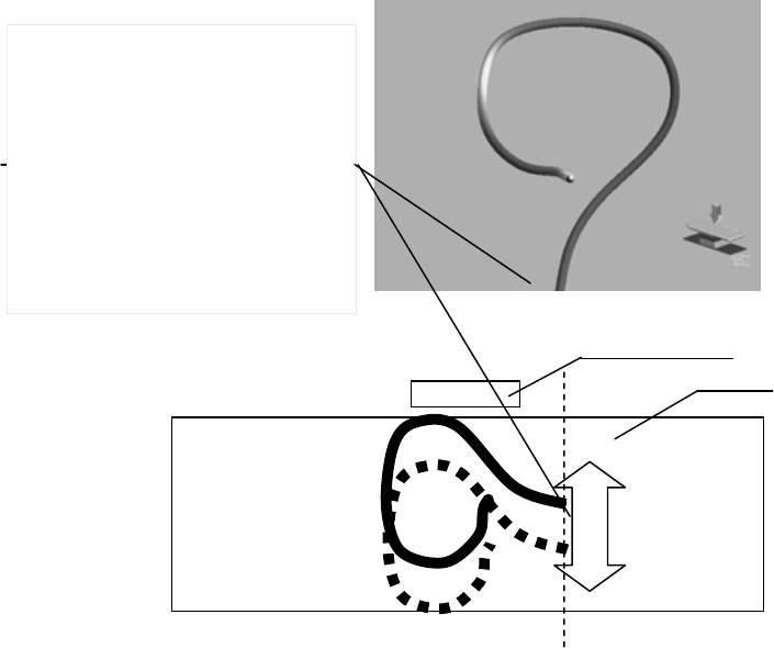
112
monitor display corresponds to the start position of the scope model.
OFF The scope model moves according to the actual endoscope’s movement.
Figure When the start position of the scope model is set to “ON”
Actual endoscope’s positioning (top view) Receiver dish
Operation table
Start position of the scope model
The scope model is always
displayed in the center of the
screen regardless the actual
endoscope’s movement.
CONFIDENTIAL
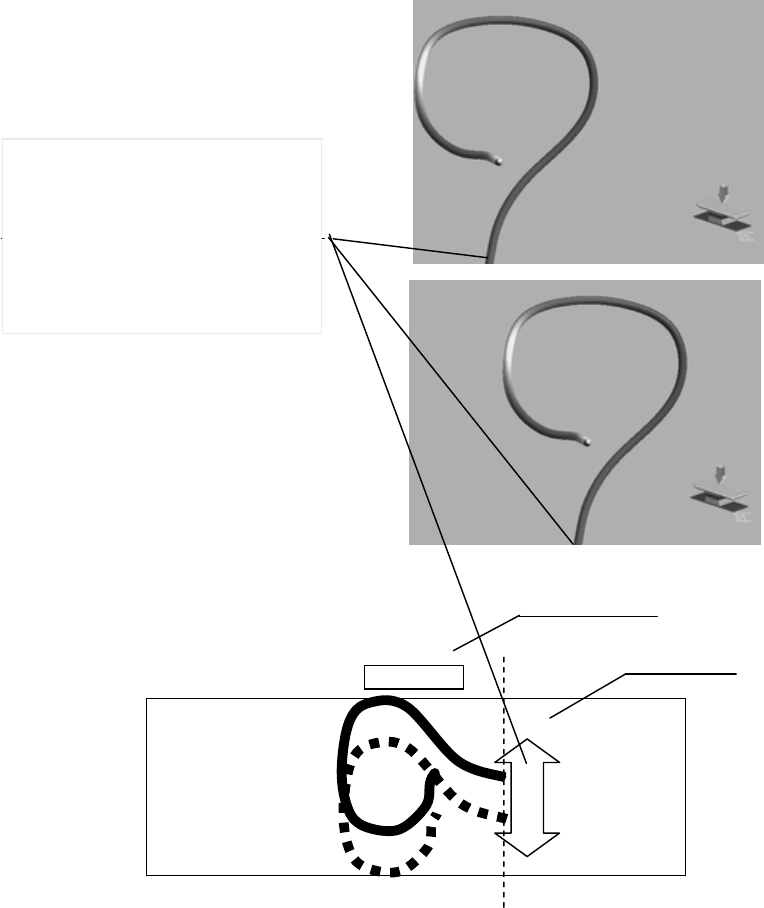
113
Figure When the start position of the scope model is set to “ON”
Actual endoscope’s positioning (top view) Receiver dish
Operation table
Start position of the scope model
The scope model is displayed
according to the actual
endoscope’s movement.
CONFIDENTIAL
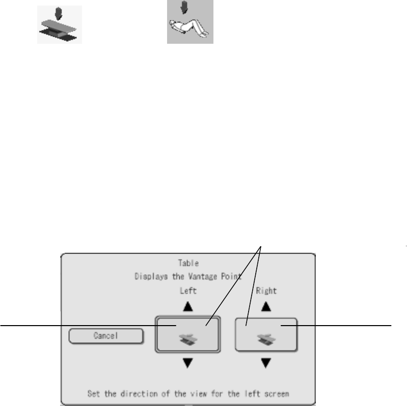
114
○Changing the viewing image
1. Select the viewing image.
Setting value Description
Operating table image Displays the operating table image.
Figure image Displays the figure image.
Operating table image Figure image
○For operating table image
Set the view angle of the operating table image in respective left and right sides of the split
screen.
1. Move the cursor on the "Left screen” and press the “ENTER” button on the control panel.
2. Press the Zoom in or Zoom out button to select the view(ing) angle in the left screen.
3. Move the cursor on the “Right screen” and press the “ENTER” button on the control
panel.
4. Press the Zoom in or Zoom out button to select the view(ing) angle in the right screen.
5. Press the “MENU” button to close the window.
Left screen Right screen
Possible choices of the viewing angles
CONFIDENTIAL
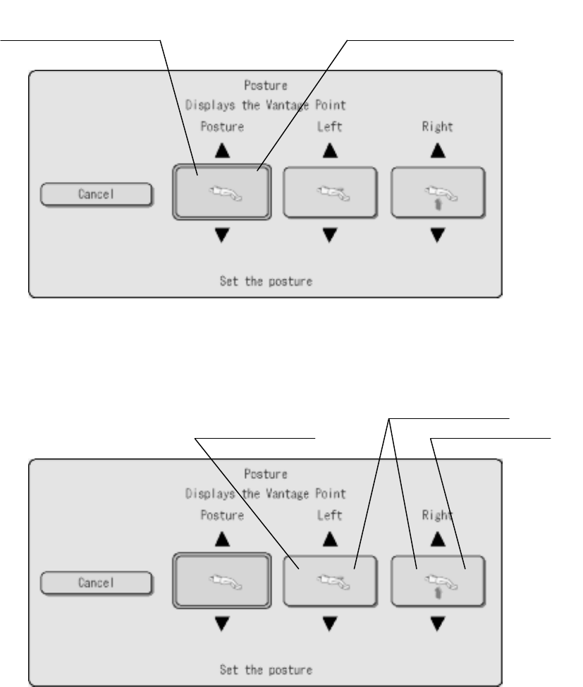
115
○For figure image
Set the view angle of the figure image in respective left and right sides of the split screen.
1. Move the cursor on the "Posture” and press the “ENTER” button on the control panel.
2. Press the Zoom in or Zoom out button to select the posture of the figure image.
3. Move the cursor on the “Left screen” and press the “ENTER” button on the control panel.
4. Press the Zoom in or Zoom out button to select the view(ing) angle in the left screen.
Possible choices of the
postures of figure images
Posture of the figure image
Possible choices of view angles
Left side of the split screen
Right side of the split screen
CONFIDENTIAL
116
5. Move the cursor on the “Right screen” and press the “ENTER” button on the control
panel.
6. Press the Zoom in or Zoom out button to select the view(ing) angle in the right screen.
[NOTE]
• The view angle against the figure image can be selected from four angles: anterior,
posterior, right lateral, or left lateral. Other angles cannot be selected.
• The view angle in the left side of the split screen can be selected as either anterior or
posterior. The view angle in the right side of the split screen can be selected as either right
lateral or left lateral.
• The view angle in the single screen is the same as selected for the front/back view or
lateral view. Other angles cannot be selected.
○
Displaying the viewpoint indicator arrow
1. Set the display of the viewpoint indicator arrow for the figure image.
Setting value Description
ON Displays the viewpoint indicator arrow for the figure image.
OFF Not display the viewpoint indicator arrow for the figure image.
○
Displaying position of the figure image
1. Set the displaying position of the figure image
Setting value Description
Lower left Displays the figure image at the lower left part of the screen.
Upper right Displays the figure image at the upper right part of the screen.
○
Displaying the AP symbol
1. Set the display of the AP icon in the left screen in the split-screen display mode.
Setting value Description
ON Displays the AP symbol in the left screen.
OFF Not display the AP symbol in the left screen.
CONFIDENTIAL
117
○
Automatic resetting of the posture of the figure image
1. Set automatic resetting of the viewing angle and the posture of the figure image at
completion of the examination.
Setting value Description
ON Resets the viewing angle automatically at completion of the examination.
OFF Not reset the viewing angle automatically at completion of the
examination.
[NOTE]
For the method to change the viewing angle, see Section 5.1 “Rotating the scope model”.
○Single screen
1. Set the view angle in the single screen.
Setting value View angle in the single screen
Left side The view angle in the left side of the split screen.
Right side The view angle in the right side of the split screen.
○Setting the background color in right and left sides of the split screen
1. The background color of the respective right and left sides of the split screens can be
selected.
Setting value
Black
Green
Blue
CONFIDENTIAL
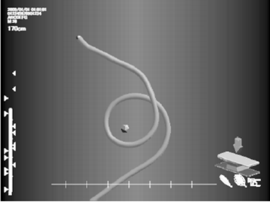
118
Bluish violet gradation
○Resetting
1. Select whether the view angle is reset automatically at the end of the examination.
Setting value Description
ON Resets the view angle automatically at the end of the examination.
OFF Not reset the view angle automatically at the end of the examination.
[NOTE]
For changing the view angle, refer to Section 5.1, “Rotating the scope model”.
○Displaying the viewpoint indicator arrow
1. Select whether the viewpoint indicator arrow for the figure image is displayed.
Setting value Description
ON Displays the viewpoint indicator arrow for the figure image.
OFF Not display the viewpoint indicator arrow for the figure image.
CONFIDENTIAL
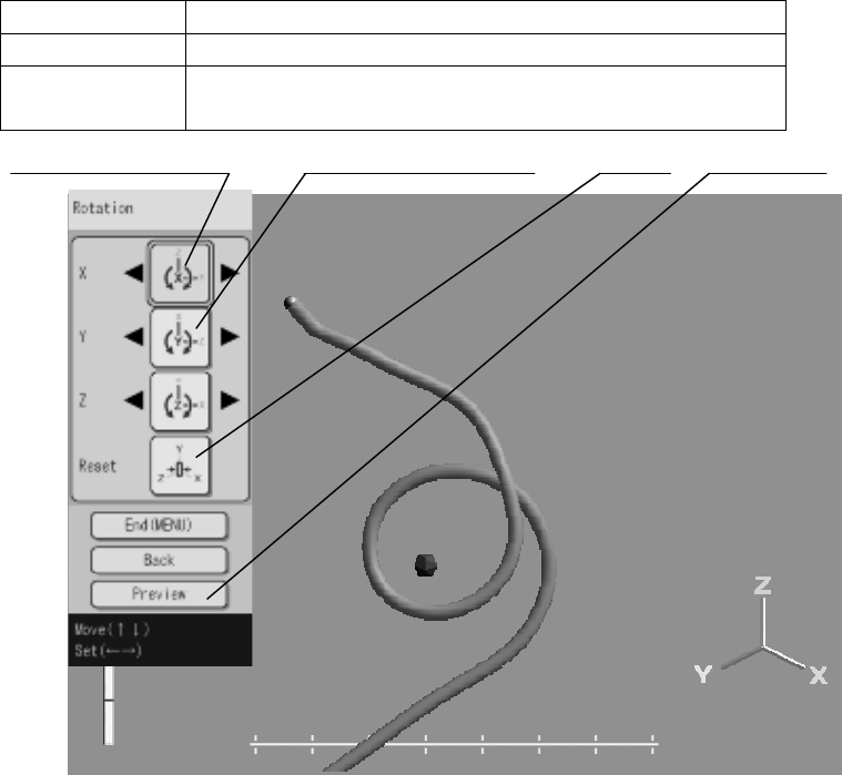
119
8.4 Adjustment
○Submenu of adjustment
1. Move the cursor on the “Adjustment” in the submenu list and press the “ENTER” button
on the control panel to display the window for adjustment.
2. Move the cursor on the category to be adjusted and press the “ENTER” button on the
control panel.
○Fine correction for rotation
The view angle can be corrected.
1. Move the cursor on the “X axis” and press the “ROTATE LEFT” or “ROTATE RIGHT”
button on the control panel to rotate the scope model.
Button Rotation of the scope model
ROTATE LEFT
Rotates 2.5 degrees in an upward direction.
ROTATE
RIGHT Rotates 2.5 degrees in a downward direction.
Up/downward rotation Right/leftward rotation Reset Preview
CONFIDENTIAL
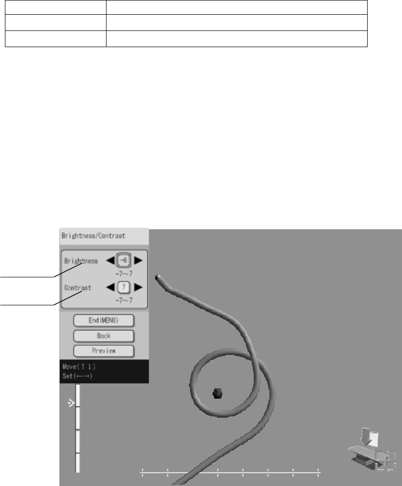
120
2. Move the cursor on the “Right/leftward rotation” and press the “ROTATE LEFT” or
“ROTATE RIGHT” button on the control panel to rotate the scope model. The followings are
the buttons and their rotation directions and angles.
Button Rotation of the scope model
ROTATE LEFT Rotates 2.5 degrees in a leftward direction.
ROTATE RIGHT Rotates 2.5 degrees in a rightward direction.
3. Move the cursor on the “Preview” button and press the “ENTER” button to reduce the
size of menu list. Press the “ENTER" button again return the small size of menu list to its
original size.
4. After the setup is completed, press the “MENU” button on the control panel.
○Brightness and contrast adjustment
1. Move the cursor on the “Brightness” button and press the “ROTATE RIGHT” or
“ROTATE LEFT” button to adjust the brightness.
2. Move the cursor on the “Contrast” button and press the “ROTATE RIGHT” or “ROTATE
LEFT” button to adjust the brightness.
3. Move the cursor on the “Preview” button and press the “ENTER” button to reduce the
size of menu list. Press the “ENTER" button again return the small size of menu list to its
original size.
Brightness
Contrast
CONFIDENTIAL
121
4. After the setup is completed, press the “MENU” button on the control panel.
CONFIDENTIAL

122
Chapter 9 Troubleshooting
If the endoscope position detecting unit is visibly damaged, does not function as expected,
or is found to have irregularities during the inspection described in Chapter 3, “Inspection”
and Chapter 7, “Installation and Connection”, or the use described in Chapter 4,
“Operation”, do not use the endoscope position detecting unit and contact Olympus. Some
problems that appear to be malfunctions may be correctable by referring to Section 9.1,
“Troubleshooting guide”. If the problem cannot be resolved by the described remedial action,
stop using the endoscope position detecting unit and contact Olympus.
[DANGER]
Never use the endoscope position detecting unit if an abnormality is suspected. Damage or
irregularity in the instrument may compromise patient or user safety and may result in
more severe equipment damage.
9.1 Troubleshooting guide
The following table shows the possible causes of and countermeasures against troubles that
may occur due to equipment setting errors or deterioration of consumable.
Troubles or failures other than those listed in the following table need repair. As repair
performed by persons who are not qualified by Olympus could cause patient or user injury
and/or equipment damage, be sure to contact Olympus for repair.
Irregularity
description Possible cause Solution
The endoscope position
detecting unit is not
connected to a
hospital-grade power
outlet.
Connect the endoscope
position detecting unit to the
power outlet using the power
cord.
The endoscope position
detecting unit cannot
be turned on.
Power is not supplied to
the hospital-grade
power outlet.
Supply power properly to the
power outlet.
The setup menu is
being displayed. Display the scope model as
described in “Saving and
recalling the display setup”.
The scope model is not
displayed on the
monitor.
The UPD cable is not
connected. Connect the UPD cable.
CONFIDENTIAL

123
The UPD cable is not
connected to the
endoscope.
Connect the UPD cable to the
endoscope.
The monitor cable is not
connected. Connect the monitor cable.
The monitor cable
failure. Replace the monitor cable.
The reference plate
(MAJ-1860) is attached
improperly to the
patient’s body.
Attach the reference plate
properly to the patient’s body
as described in “Attaching the
reference plate (MAJ-1860) to
the patient’s body”.
Set an optimum zooming
ratio.
The scope model
zooming ratio is
improper. Press the reset switch to
initialize the zooming ratio.
Set an optimum rotation
angle.
The scope model
rotation angle is
improper. Press the reset switch to
initialize the rotation angle.
The monitor display is
disturbed. The monitor cable
failure. Replace the monitor cable.
A strong magnetic field
source is near the
endoscope position
detecting unit.
Move the endoscope position
detecting unit away from the
strong magnetic field source.
Decrease the display speed of
the scope model. See Section
8.2 “System setup”.
The scope model
display is unstable.
There is a large metallic
object near the
endoscope position
detecting unit.
Move the endoscope position
detecting unit away from the
large metallic object.
CONFIDENTIAL

124
The reference plate
(MAJ-1860) is attached
improperly to the
patient’s body.
Attach the reference plate
properly to the patient’s body
as described in “Attaching the
reference plate (MAJ-1860) to
the patient’s body”.
A strong magnetic field
source is near the
endoscope position
detecting unit.
Move the endoscope position
detecting unit away from the
strong magnetic field source.
Decrease the display speed of
the scope model. See Section
8.2 “System setup”.
There is a large metallic
object near the
endoscope position
detecting unit.
Move the endoscope position
detecting unit away from the
large metallic object.
The scope model
display is distorted.
The material and/or
structure of the
operating table causes
distortion of the scope
model.
Contact Olympus.
Patient data is not
displayed. The video system center
is not connected.
Connect the video system
center as described in
“Connection to the video
system center”.
CONFIDENTIAL

125
○ Error messages
Message Possible cause Solution
The scope shape can not be
displayed. CLV-UPD cable is
not connected, or there is
malfunction in endoscope,
CLV-UPD cable or CLV.
When the problem is not
solved even if the CLV-UPD
cable is reconnected, please
contact the Olympus service
center.
The scope shape cannot be
displayed. The scope
connection may be wet.
Check the connection and
re-insert the scope again. If
the error continues, please
contact the Olympus service
center.
The scope shape can not be
displayed. There is
malfunction in endoscope or
UPD cable. Please contact the
Olympus service center.
The endoscope or
connection cable can be
malfunctioning.
•Contact Olympus.
•If another endoscope functions
normally, the endoscope has
been used can be
malfunctioning.
The receiver dish or receiver
dish cable is not connected.
Please connect the receiver
dish or receiver dish cable.
The receiver dish cable is
connected incorrectly.
For connecting the receiver dish
cable, refer to Section 7.3,
“Installation of the receiver dish”.
There is malfunction in
UPD-3. Please contact the
Olympus service center.
The date/time internal battery
has expired. As a result, the
date/time may be inaccurate.
Please contact the Olympus
service center.
The internal battery for
saving the date and time
data is dead.
•Contact Olympus.
The previously used settings
could not be restored. All
settings will be restored to
factory settings. Please apply
custom settings afterwards as
needed.
Saving the previous
settings has failed.
All settings return to the factory
default settings. Reset the all
settings.
The scope position could not When the display range Move the reference plate to a
CONFIDENTIAL

126
be set. The reference plate is
out of the setting range for
scope position. Change the
reference plate to tracking
mode, then set the scope
position again.
of the scope model is set,
the reference plate was
located outside of the
detection area of the
receiver dish.
location within the detection
area of the receiver dish and
perform the setting again. See
Section 5.7 “Setting the scope
model display range”.
The scope position settings
could not be set. There is
malfunction in the hand coil.
Please contact the Olympus
service center.
The hand coil may be
malfunctioning.
Contact Olympus.
The scope position could not
be set. The scope or probe is
not connected. Please
connect the scope or probe
and set the scope position
again.
Setting the scope model
display range was
performed without
connecting the
endoscope or the position
detecting probe to the
endoscope position
detecting unit.
Connect the endoscope or the
position detecting probe to the
endoscope position detecting
unit.
The bookmark was not saved.
Bookmarks cannot exceed 50
per case. Please delete an
existing bookmark before
saving a new one.
More than 50 markings
attempt to be put.
Delete the all markings and put
new markings again. See
Section 5.6, “Marking”.
The hand coils can not be
used because two hand coils
are connected at the same
time. Please do not connect
the hand coil which will not be
used.
The hand coils were
connected to both the
main unit and the
connection unit.
Disconnect either of the hand
coils connected to the main unit
and the connection unit.
The reference plate can not
be used because two
reference plates are
connected at the same time.
Please do not connect the
reference plate which will not
be used.
The reference plates
were connected to both
the main unit and the
connection unit.
Disconnect either of the
reference plates connected to
the main unit and the
connection unit
The scope shape can not be
displayed because the
connection with the video
system center was lost.
Please check the video
system center connection.
Remote connection settings
CONFIDENTIAL

127
with the video system center
are not correct. Please
change the remote connection
settings to LINK-IN.
There is an error in date input
field. Are you sure you want to
exit without saving?
The hand coil switch is
depressed. Please check the
switch.
The front panel or remote
controller button is depressed.
Please check the buttons.
Writing settings from the
maintenance computer.
Please do not turn off the
power to the UPD-3 until the
writing process is complete.
The settings cannot be
restored because no backup
data exists.
This will restore the factory
settings and delete all data.
Are you sure you want to
proceed?
CONFIDENTIAL
128
9.2 Returning the endoscope position detecting unit
for repair
[CAUTION]
Olympus is not liable for any injury or damage which occurs as a result of repairs
attempted by non-Olympus personnel.
When returning the video system center for repair, contact Olympus. With the video
system center, include a description of the malfunction or damage and the name and
telephone number of the individual at your location who is most familiar with the problem.
Include a repair purchase order.
[NOTE]
When the accessories of the position detecting unit, contact Olympus to purchase a
replacement.
CONFIDENTIAL

129
Appendix
System chart (1/3)
RECEIVER DISH MAJ-1868RECEIVER DISH MAJ-1868
RECEIVER DISH CABLE
MAJ-1927
RECEIVER DISH CABLE
MAJ-1875
RECEIVER DISH CABLE
MAJ-1927
RECEIVER DISH CABLE
MAJ-1875
RECEIVER DISH STAND
MAJ-1907
RECEIVER DISH ARM
MAJ-1962
RECEIVER DISH STAND
MAJ-1907
RECEIVER DISH ARM
MAJ-1962
UPD-Y0003UPD-Y0003
: These items are used exclusively
: shows accessories of UPD-Y0003
: Part of this submission
: These items are used exclusively
CISPR11 Class B
RECEIVER DISH STAND
SUPPLEMENTARY SET MAJ-1978
HOLDER
ATTACHMENT REMOTE CONTROL
HOLDER
MP HOLDER
CONNECTION
UNIT COVER
CABLE POCKETCONNECTION
UNIT HOLDER
M PLATE
RECEIVER DISH STAND
SUPPLEMENTARY SET MAJ-1978
HOLDER
ATTACHMENT REMOTE CONTROL
HOLDER
MP HOLDER
CONNECTION
UNIT COVER
CABLE POCKETCONNECTION
UNIT HOLDER
M PLATE
UNIFIED CABLE MAJ-1964UNIFIED CABLE MAJ-1964
RECEIVER DISH MAJ-1868RECEIVER DISH MAJ-1868
RECEIVER DISH CABLE
MAJ-1927
RECEIVER DISH CABLE
MAJ-1875
RECEIVER DISH CABLE
MAJ-1927
RECEIVER DISH CABLE
MAJ-1875
RECEIVER DISH STAND
MAJ-1907
RECEIVER DISH ARM
MAJ-1962
RECEIVER DISH STAND
MAJ-1907
RECEIVER DISH ARM
MAJ-1962
UPD-Y0003UPD-Y0003
: These items are used exclusively
: shows accessories of UPD-Y0003
: Part of this submission
: These items are used exclusively
: These items are used exclusively: These items are used exclusively
: shows accessories of UPD-Y0003: shows accessories of UPD-Y0003
: Part of this submission: Part of this submission
: These items are used exclusively: These items are used exclusively
CISPR11 Class B
RECEIVER DISH STAND
SUPPLEMENTARY SET MAJ-1978
HOLDER
ATTACHMENT REMOTE CONTROL
HOLDER
MP HOLDER
CONNECTION
UNIT COVER
CABLE POCKETCONNECTION
UNIT HOLDER
M PLATE
RECEIVER DISH STAND
SUPPLEMENTARY SET MAJ-1978
HOLDER
ATTACHMENT REMOTE CONTROL
HOLDER
MP HOLDER
CONNECTION
UNIT COVER
CABLE POCKETCONNECTION
UNIT HOLDER
M PLATE
UNIFIED CABLE MAJ-1964UNIFIED CABLE MAJ-1964
UPD
-
3
CONFIDENTIAL
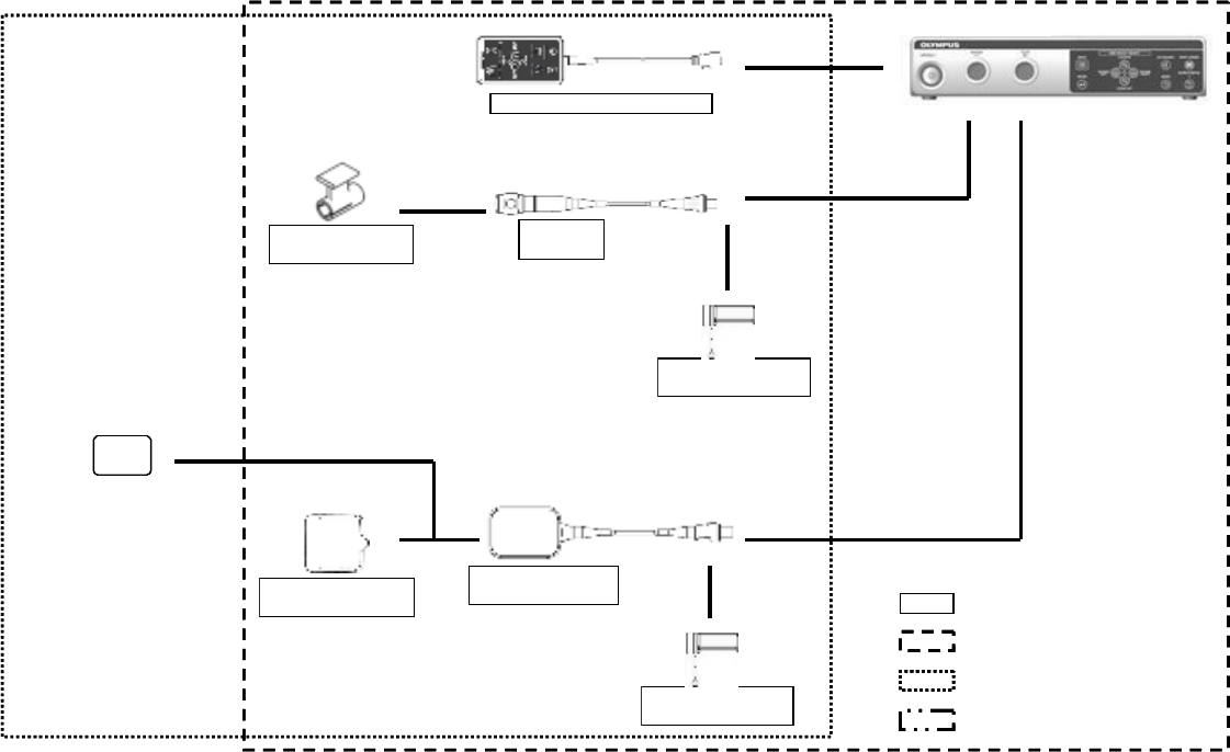
130
System chart (2/3)
REMOTE CONTROL MAJ-1890REMOTE CONTROL MAJ-1890
HAND COIL COVER
MAJ-1879
HAND COIL COVER
MAJ-1879
REFERENCE PLATE
COVER MAJ-1880
REFERENCE PLATE
COVER MAJ-1880
WATER-RESISTANT
CAP MAJ-1899
WATER-RESISTANT
CAP MAJ-1899
WATER-RESISTANT
CAP MAJ-1899
WATER-RESISTANT
CAP MAJ-1899
UPD-Y0003UPD-Y0003
HAND COIL
MAJ-1859
HAND COIL
MAJ-1859
REFERENCE PLATE
MAJ-1860
REFERENCE PLATE
MAJ-1860
CISPR11 Class B
REFERENCE PLATE BELT
MAJ-1029
REFERENCE PLATE BELT
MAJ-1029
: These items are used exclusively
: shows accessories of UPD-Y0003
: Part of this submission
: These items are used exclusively
: These items are used exclusively: These items are used exclusively
: shows accessories of UPD-Y0003: shows accessories of UPD-Y0003
: Part of this submission: Part of this submission
: These items are used exclusively: These items are used exclusively
UPD
-
3
CONFIDENTIAL
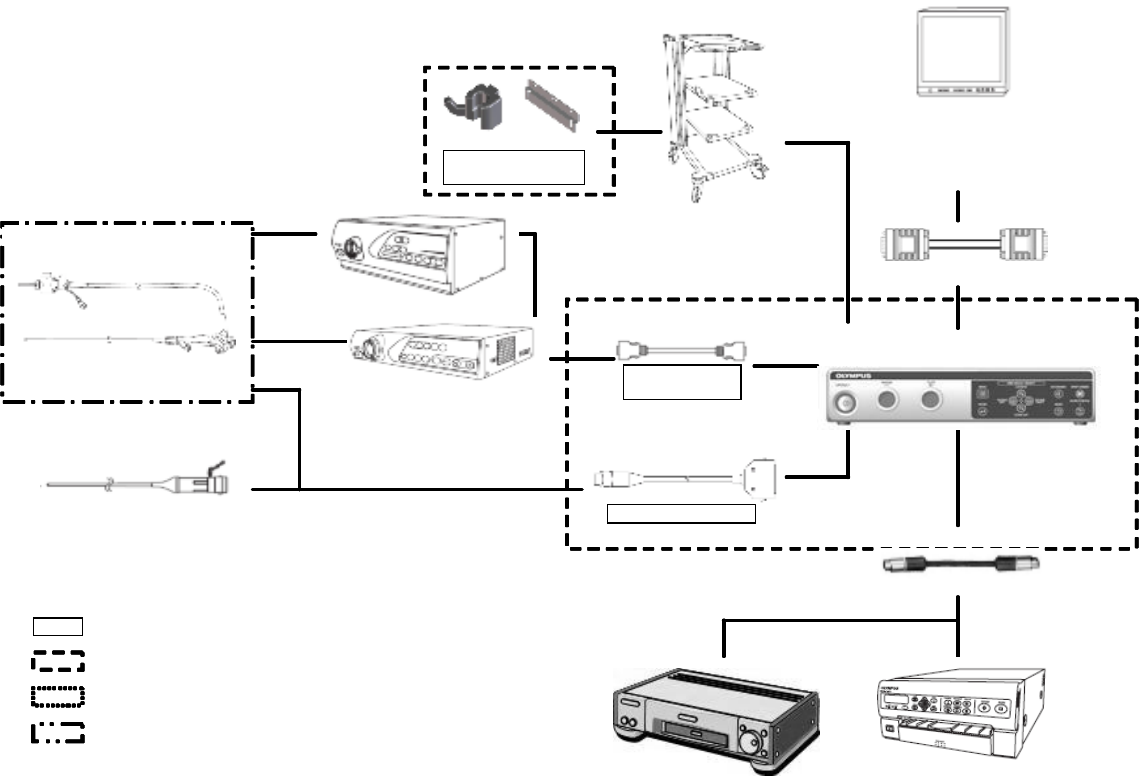
131
System chart (3/3)
POSITION DETECTING PROBE
MAJ-1300
POSITION DETECTING PROBE
MAJ-1300
DATA TRANSFER
CABLE MAJ-604
DATA TRANSFER
CABLE MAJ-604
UPD CABLE MAJ-1881UPD CABLE MAJ-1881
CISPR11 Class A
UPD-Y0003UPD-Y0003
CISPR11 Class B
Y/C cable MH-985Y/C cable MH-985
WM-NP1, WM-W P1WM-NP1, WM-W P1
Video Tape Recorder Video Tape Recorder
HOLDER FOR HC-RP
MAJ-1938
HOLDER PLATE
HOLDER FOR HC-RP
MAJ-1938
HOLDER PLATE
COLOR VIDEO PRINTER
OEP-3,OEP-4
COLOR VIDEO PRINTER
OEP-3,OEP-4
: These items are used exclusively
: shows accessories of UPD-Y0003
: Part of this submission
: These items are used exclusively
CLV-160, CLV-180CLV-160, CLV-180
CV-160, CV-165, CV-180CV-160, CV-165, CV-180
COLONOVIDEOSCOPE
CF-Q160DL/I, CF-H180DL/I
COLONOVIDEOSCOPE
CF-Q160DL/I, CF-H180DL/I
Video Monitor
ET 1528L-7CWM-1-BG-G
(Elo TouchSystems,Inc.)
PLT210-W0X
(TOTOKU ELECTRIC CO. LTD)
Video Monitor
ET 1528L-7CWM-1-BG-G
(Elo TouchSystems,Inc.)
PLT210-W0X
(TOTOKU ELECTRIC CO. LTD)
VGA video cableVGA video cable
POSITION DETECTING PROBE
MAJ-1300
POSITION DETECTING PROBE
MAJ-1300
DATA TRANSFER
CABLE MAJ-604
DATA TRANSFER
CABLE MAJ-604
UPD CABLE MAJ-1881UPD CABLE MAJ-1881
CISPR11 Class A
UPD-Y0003UPD-Y0003
CISPR11 Class B
Y/C cable MH-985Y/C cable MH-985
WM-NP1, WM-W P1WM-NP1, WM-W P1
Video Tape Recorder Video Tape Recorder
HOLDER FOR HC-RP
MAJ-1938
HOLDER PLATE
HOLDER FOR HC-RP
MAJ-1938
HOLDER PLATE
COLOR VIDEO PRINTER
OEP-3,OEP-4
COLOR VIDEO PRINTER
OEP-3,OEP-4
: These items are used exclusively
: shows accessories of UPD-Y0003
: Part of this submission
: These items are used exclusively
: These items are used exclusively: These items are used exclusively
: shows accessories of UPD-Y0003: shows accessories of UPD-Y0003
: Part of this submission: Part of this submission
: These items are used exclusively: These items are used exclusively
CLV-160, CLV-180CLV-160, CLV-180
CV-160, CV-165, CV-180CV-160, CV-165, CV-180
COLONOVIDEOSCOPE
CF-Q160DL/I, CF-H180DL/I
COLONOVIDEOSCOPE
CF-Q160DL/I, CF-H180DL/I
Video Monitor
ET 1528L-7CWM-1-BG-G
(Elo TouchSystems,Inc.)
PLT210-W0X
(TOTOKU ELECTRIC CO. LTD)
Video Monitor
ET 1528L-7CWM-1-BG-G
(Elo TouchSystems,Inc.)
PLT210-W0X
(TOTOKU ELECTRIC CO. LTD)
VGA video cableVGA video cable
UPD
-
3
CONFIDENTIAL

132
Transportation, storage, and operation environment
Ambient
temperature
−25 to +70°C (−13 to +158°F)
Relative
humidity 10 - 95%
Transportation
and storage
environment
Atmospheric
pressure 700 - 1060 hPa
Ambient
temperature
10 - 40°C (50 - 104°F)
Relative
humidity 30 - 85% (without condensation)
Operation
environment
Atmospheric
pressure 700 - 1060 hPa
(0.7 - 1.1 kgf/cm2)
(10.2 - 15.4 psia)
Specifications
Item Specifications
Voltage 100 – 120 VAC
220 – 240 VAC
(see the electrical rating label on the
rear panel)
fluctuation ±10%
Frequency 50/60 Hz
Frequency
Fluctuation ±1 Hz
Power supply
Input current 100VA (at 100 – 240 VAC)
Dimensions 370 (W) × 80.7 (H) ×482 (D) mm Size
Weight 9 kg
Type of protection
against electric
shock
Class I
Classification
(medical
electrical
equipment)
Degree of protection
against electric
shock of applied part
TYPE BF applied part
Where no classification mark appears,
the equipment is a TYPE BF applied
part.
CONFIDENTIAL

133
Item Specifications
Explosion proofing
degree
Use in a flammable atmosphere is
prohibited
XGA 1024×768
Horizontal frequency 48.5kHz
Vertical frequency 60Hz
Y/C NTSC, PAL
Video signal
outputs
SD-SDI SMPTE259M
CONFIDENTIAL
134
Item Specifications
Medical
Device
Directive
(For 220 – 240
V
type
equipment)
This device complies with the
requirements of Directive 93/42/EEC
concerning medical devices.
Classification: Class II a
This device complies with the EMC
requirements of EN 60601-1-2: 2001
when used in combination with devices
bearing CE marking either on the
products or in its instructions for use.
Emission: Class A of EN 55011
WEEE
Directive
(For 220 – 240
V
type
equipment)
In accordance with European Directive
2002/96/EC on Waste Electrical and
Electronic Equipment, this symbol
indicates that the product must not be
disposed of as unsorted municipal
waste, but should be collected
separately.
Refer to your local Olympus distributor
for return and/or collection systems
available in your country.
EMC
Applied standard;
IEC 60601-1-2: 2007 This instrument complies with the
standards listed in the left column.
CISPR 11 of emission:
Group 1, Class B
This instrument complies with the EMC
standard for medical electrical
equipment; edition 3 (IEC 60601-1-2:
2007). However, when connecting to an
instrument that complies with the EMC
standard for medical electrical
equipment; edition 1 (IEC 60601-1-2:
1993), the whole system complies with
edition 1.
CONFIDENTIAL

135
Item Specifications
Year of
manufacture 7001234
↑ The last digit of the
year of manufacture is
the second digit of the
serial number.
The last digit of the year of manufacture
Degree of
protection
against electric
shock
Reference plate Hand
coil TYPE BF applied part
Specification of radio transmitter
Center frequency: 9.888Hz, 10.712Hz, 11.536Hz
Bandwidth: ±20Hz
Modulation No modulation
RF (Radio Frequency) output power:
70dBμV/m or less (at a distance of 3 meters)
CONFIDENTIAL
136
EMC information
This model is intended for use in the electromagnetic environments specified below. The
user and the medical staff should ensure that it is used only in these environments.
○Magnetic emission compliance information and recommended electromagnetic
environments
CONFIDENTIAL
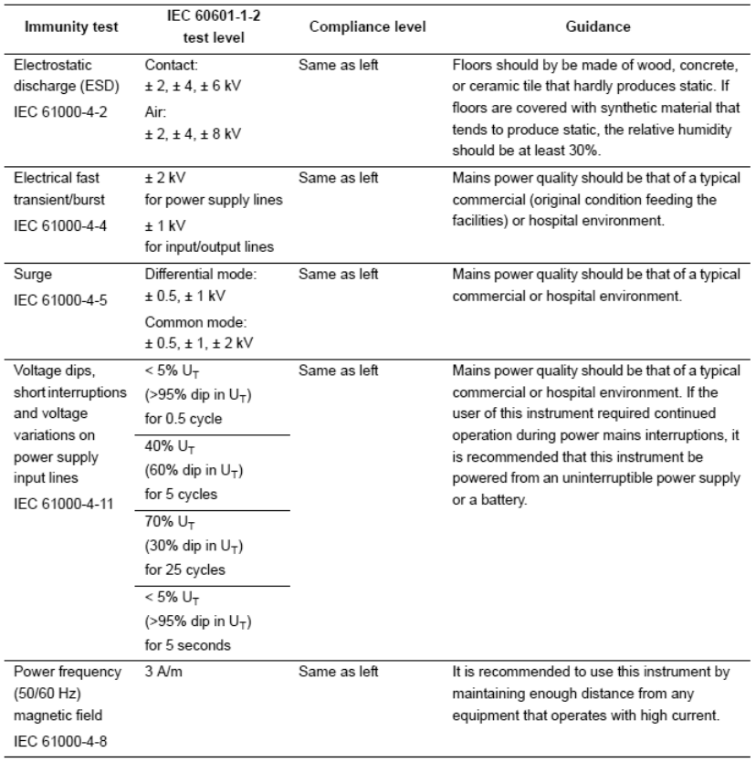
137
○ Electromagnetic immunity compliance information and recommended electromagnetic
environments
[NOTE]
UT is the a.c. mains power supply prior to application of the test level.
CONFIDENTIAL
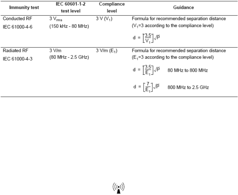
138
○ Cautions and recommended electromagnetic environment regarding portable and mobile
RF communications equipment such as a cellular phones.
[NOTE]
• Where “P” is the maximum output power rating of the transmitter in watts (W) according
to the transmitter manufacturer and “d” is the recommended separation distance in meters
(m).
• This instrument complies with the requirements of IEC 60601-1-2: 2001. However, under
electromagnetic environment that exceeds its noise level, electromagnetic interference may
occur on this instrument.
• Electromagnetic interference may occur on this instrument near a high-frequency
electrosurgical equipment and/or other equipment marked with the following symbol:
CONFIDENTIAL
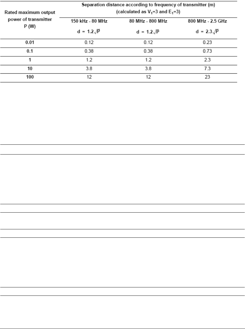
139
○ Recommended separation distance between portable and mobile RF communications
equipment and this instrument
[NOTE]
The guidance may not apply in some situations. Electromagnetic propagation is affected by
absorption and reflection from structures, objects and people. Portable and mobile RF
communications equipment such as cellular phones should be used no closer to any part of
this instrument, including cables than the recommended separation distance calculated
from the equation applicable to the frequency of the transmitter.
FCC information
This device complies with part 15 of the FCC Rules. Operation is
subject to the following two conditions:
(1) This device may not cause harmful interference, and (2) this device
must accept any interference received, including interference that
may cause undesired operation.
FCC ID:S8QUPD-3
IC information
This equipment complies with the IC RSS210.
IC: 4763B-UPD3
FCC warnings
Change or modifications not expressly approved by the party
responsible for compliance could void the user's authority to operate
the equipment.
All interface cables used to connect peripherals must be shielded in
order to comply with the limits for a digital device pursuant to
Subpart B of Part 15 of FCC Rules.
IC note
Operation is subject to the following two conditions: (1) this device
may not cause interference, and (2) this device must accept any
interference, including interference that may cause undesired
operation of the device.
CONFIDENTIAL

140
XGT6302 00 001
CONFIDENTIAL