Olympus Winter and Ibe ESG200 Electrosurgical Generator CELON Elite ESG-200 (WA90001A, WA90002A) & CELON Precision (WA90008A, WA90009A) User Manual W7093251 01 indb
Olympus Winter & Ibe GmbH Electrosurgical Generator CELON Elite ESG-200 (WA90001A, WA90002A) & CELON Precision (WA90008A, WA90009A) W7093251 01 indb
Contents
- 1. ESG200 UserMan CelonPrecision
- 2. ESG200 UserMan Celon ELITE
ESG200 UserMan Celon ELITE

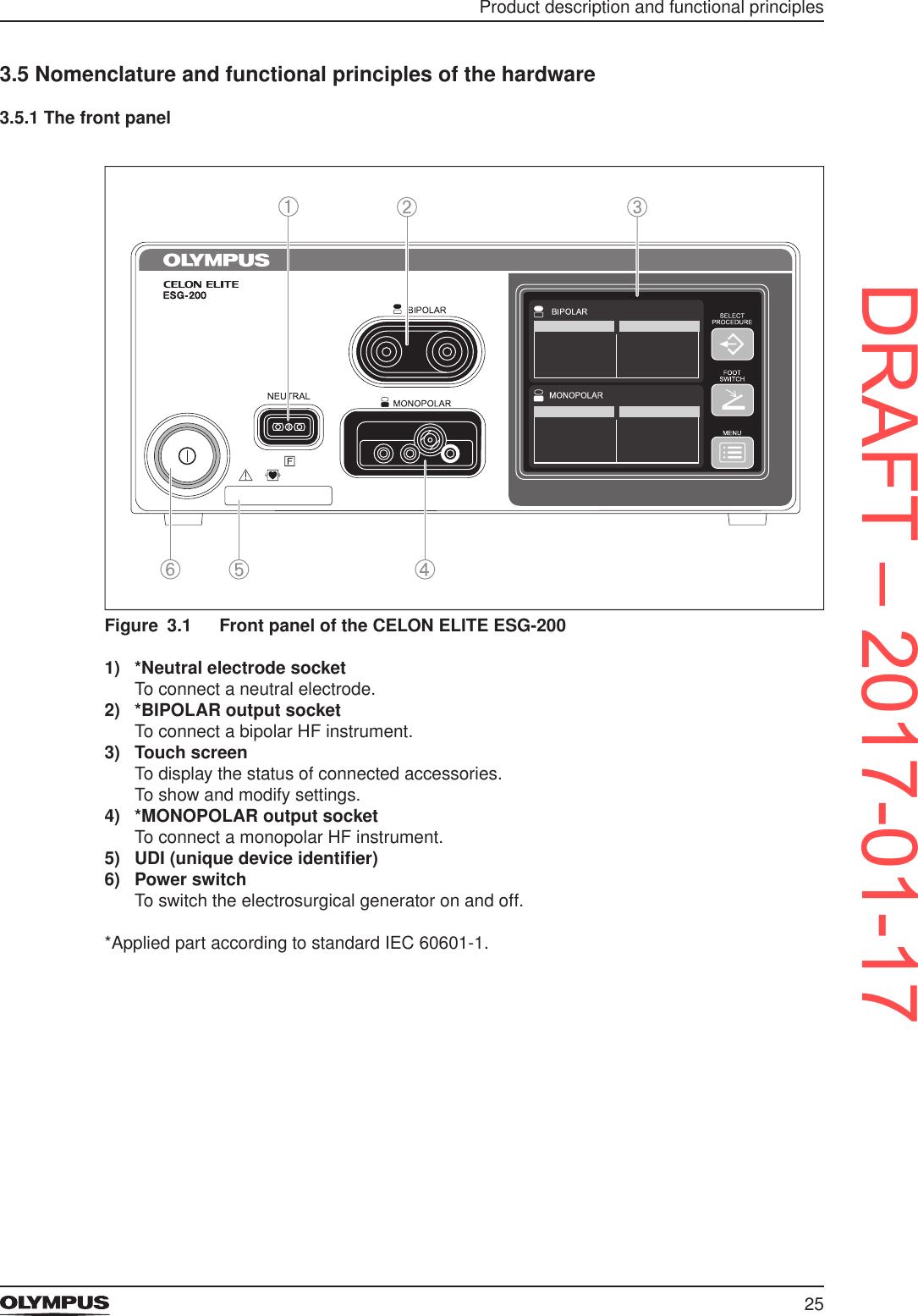
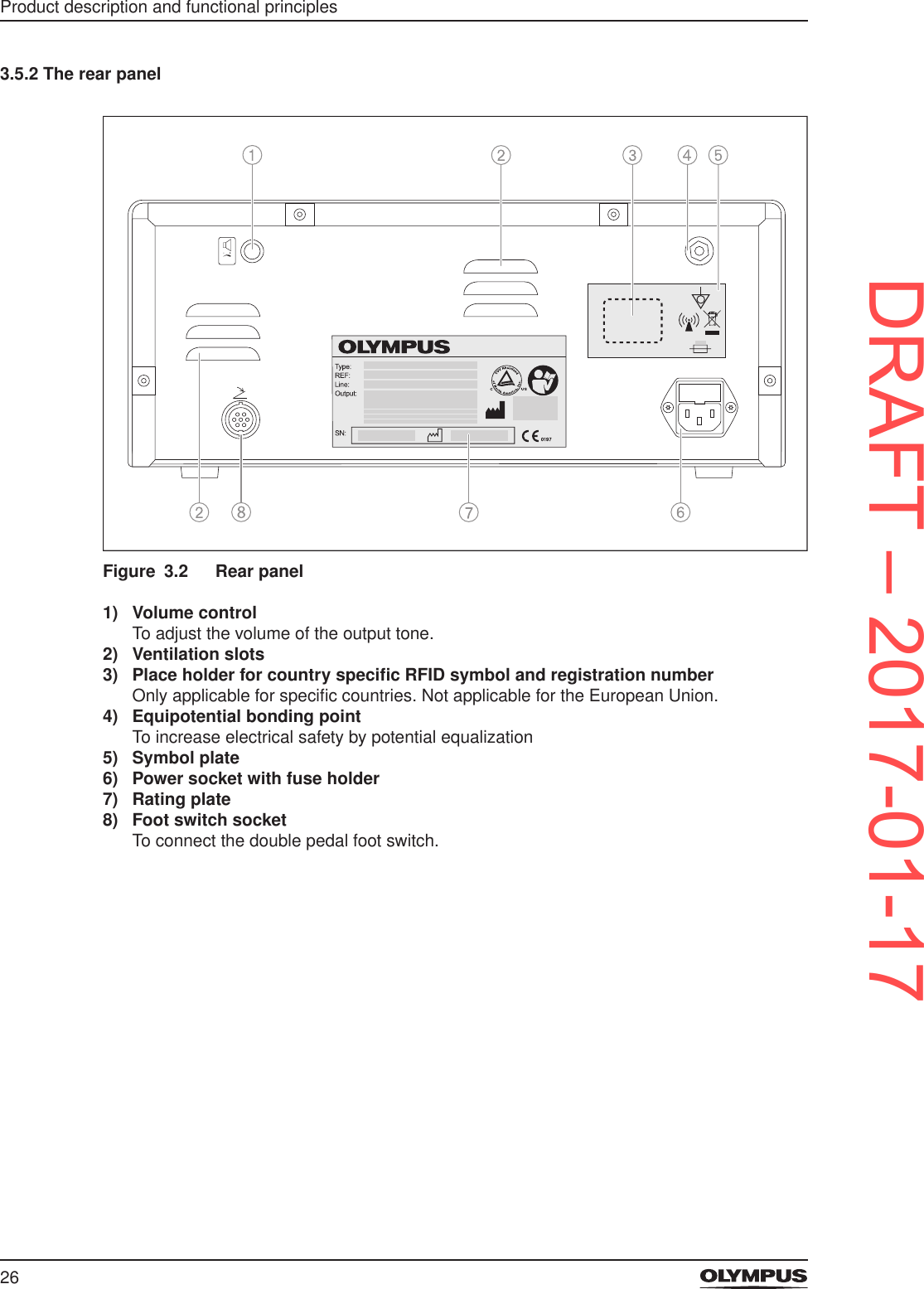
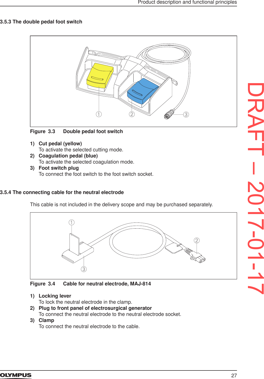
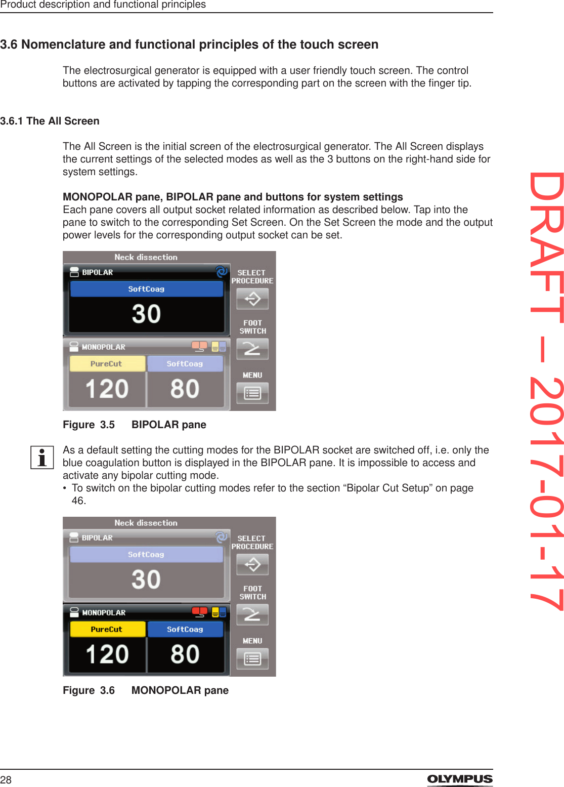
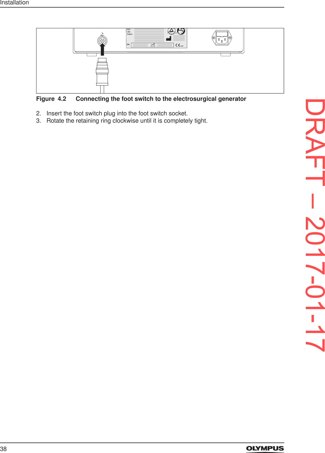
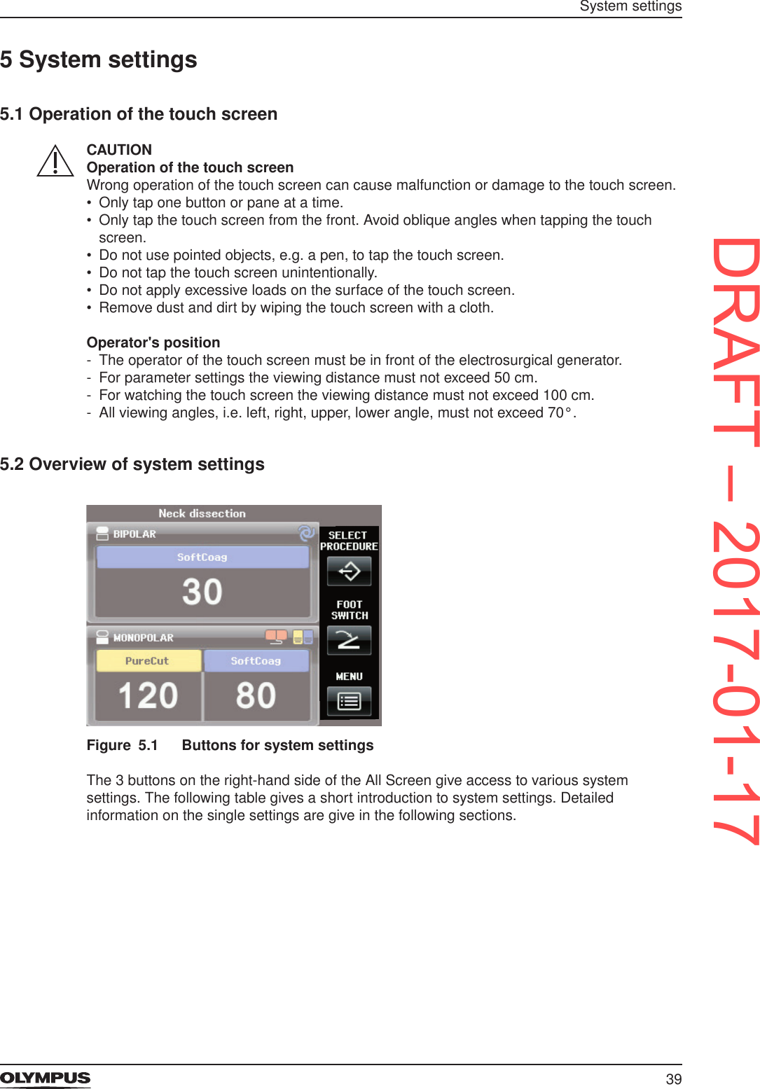
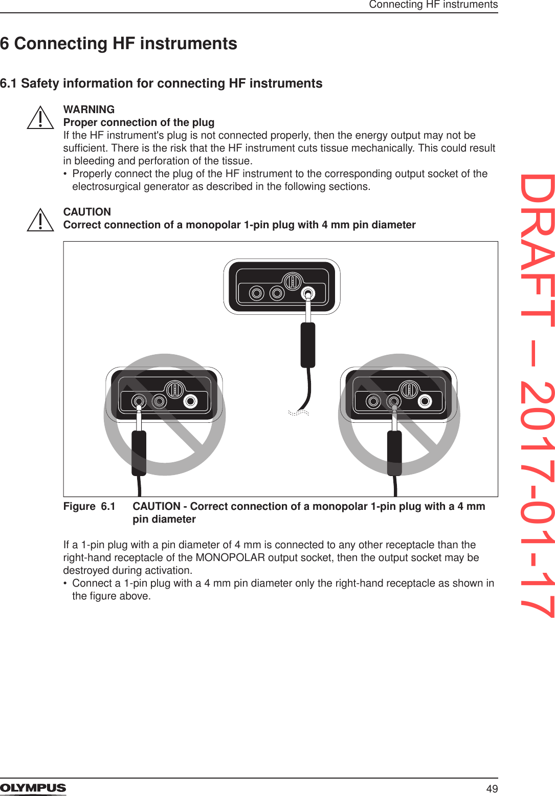
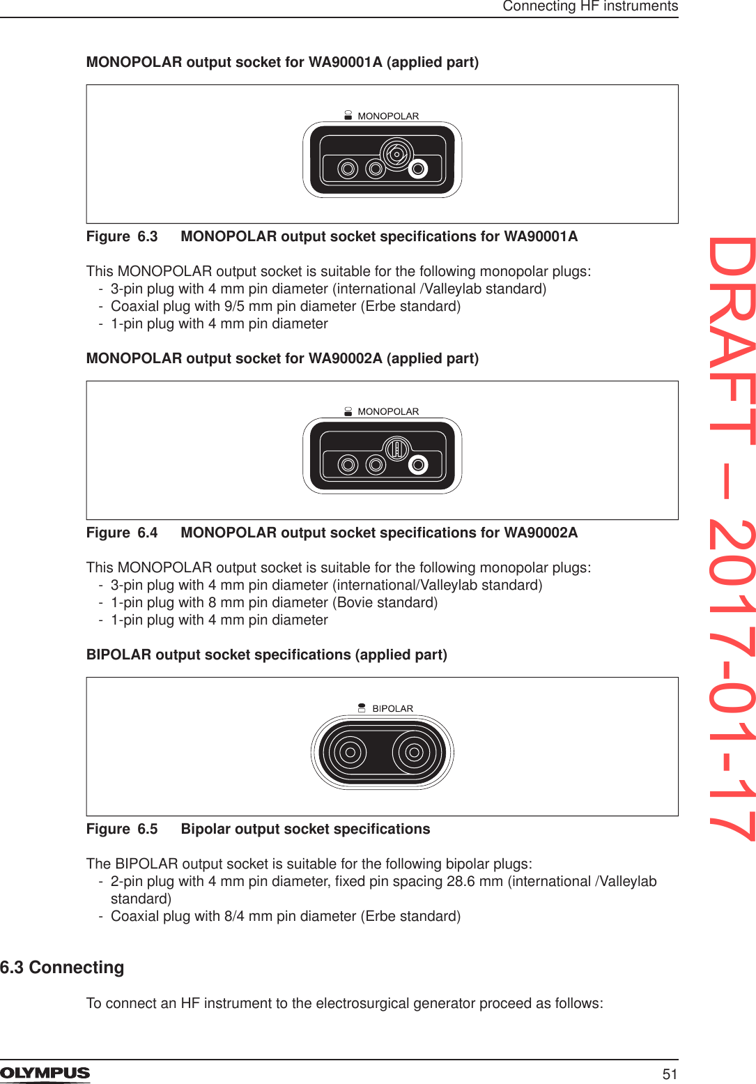
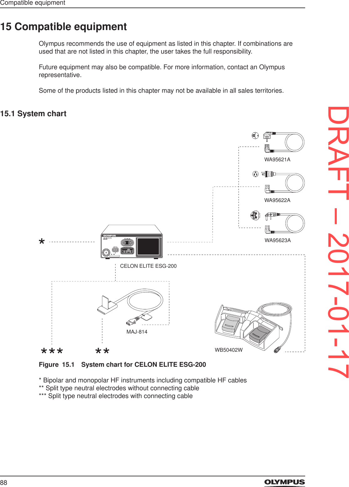
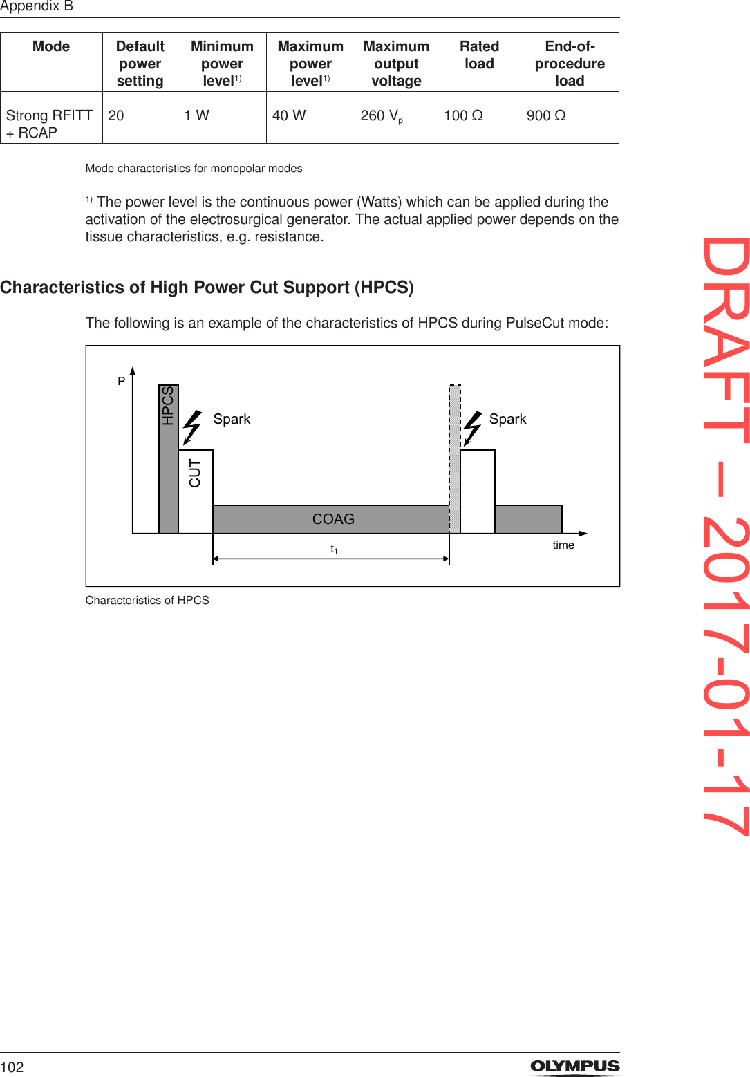
![FiguresFigure 3.1 Front panel of the CELON ELITE ESG-200..................................................25Figure 3.2 Rear panel ....................................................................................................26Figure 3.3 Double pedal foot switch ..............................................................................27Figure 3.4 Cable for neutral electrode, MAJ-814 ...........................................................27Figure 3.5 BIPOLAR pane ............................................................................................. 28Figure 3.6 MONOPOLAR pane .....................................................................................28Figure 3.7 Buttons for system settings ...........................................................................29Figure 3.8 Buttons and symbols on the All Screen ........................................................ 29Figure 3.9 Set Screen ....................................................................................................30Figure 3.10 Mode Screen for monopolar cutting .............................................................31Figure 3.11 Hierarchy list of the 3 right-hand sided buttons on the All Screen ................32Figure 4.1 Connecting the cord set to the electrosurgical generator .............................36Figure 4.2 Connecting the foot switch to the electrosurgical generator .........................38Figure 5.1 Buttons for system settings ...........................................................................39Figure 5.2 Screen [Select Procedure] ............................................................................40Figure 5.3 Screen [Assign Foot Switch] ......................................................................... 41Figure 5.4 Screen [Select Menu] ...................................................................................42Figure 5.5 Onscreen keyboard (letters and numbers) ...................................................43Figure 5.6 Onscreen keyboard (upper/lower key and backspace key) ..........................43Figure 5.7 Volume control .............................................................................................. 47Figure 5.8 Brightness control ......................................................................................... 48Figure 6.1 CAUTION - Correct connection of a monopolar 1-pin plug with a 4 mm pin diameter ........................................................................................................49Figure 6.2 CAUTION - Do not connect a 2-pin plug with 4 mm pin diameters to the MO-NOPOLAR socket .........................................................................................50Figure 6.3 MONOPOLAR output socket specications for WA90001A .........................51Figure 6.4 MONOPOLAR output socket specications for WA90002A .........................51Figure 6.5 Bipolar output socket specications..............................................................51Figure 7.1 Error message E0202 “Insufcient neutral electrode contact” ......................54Figure 7.2 Message box “Neutral electrode” ..................................................................54Figure 7.3 Connecting the plug of the neutral electrode ................................................57Figure 7.4 Fixing the neural electrode to the connecting cable .....................................57Figure 7.5 Split type indicator for CQM shining red on the Set Screen and on the All Screen ..........................................................................................................58Figure 8.6 All Screen .....................................................................................................62Figure 8.7 Set Screen for monopolar modes .................................................................63Figure 8.8 Mode Screen for monopolar cutting modes .................................................. 63Figure 8.1 Counters on the Set Screen and during activation .......................................64Figure 8.2 Error message E0660 “No bipolar cutting” ...................................................65Figure 8.3 Automatic instrument recognition .................................................................65Figure 8.4 Incompatible settings .................................................................................... 66Figure 9.1 Changing from the All Screen to the Set Screen ..........................................67Figure 9.2 Changing from the All Screen to the screen [Select Menu] ..........................68Figure 9.3 Changing from the All Screen to the screen [Assign Foot Switch] ...............68Figure 9.4 Error message E0202 “Insufcient neutral electrode contact” ......................69Figure 10.1 Error message E0115: "Activation time limit exceeded" ...............................72Figure 10.2 Background color for active coagulation on the All Screen ..........................73Figure 10.3 Background color for active coagulation on the Set Screen .........................73Figure 10.4 Error message E0141 "Power set to zero (--)" ..............................................74Figure 12.1 Error message E0002 “Short circuit” ............................................................81Figure 15.1 System chart for CELON ELITE ESG-200 ...................................................88Characteristics of HPCS ..................................................................................................102DRAFT – 2017-01-17](https://usermanual.wiki/Olympus-Winter-and-Ibe/ESG200.ESG200-UserMan-Celon-ELITE/User-Guide-3270684-Page-6.png)


![9General information1 General information1.1 User instructions • Before use, thoroughly read these instructions for use, and the instructions for use of all other products that will be used during the procedure. • If the required instructions for use are missing, immediately contact an Olympus representative. • Keep the instructions for use in a safe, accessible location.1.2 Signal wordsThe following signal words are used throughout this document.DANGERIndicates a hazardous situation which, if not avoided, will result in death or serious injury.WARNINGIndicates a potentially hazardous situation which, if not avoided, could result in death or serious injury.CAUTIONIndicates a potentially hazardous situation which, if not avoided, may result in minor or moderate injury. It may also be used to alert against unsafe practices or potential equipment damage.NOTICEIndicates a property damage message.1.3 Conventions throughout this documentThis is the safety alert symbol. It is used to alert the user to potential physical injury hazards. Observe all safety messages that follow this symbol to avoid possible injury.This symbol indicates additional helpful information.1. A numeration indicates a sequence of actions.2. ... • Bullet points indicate individual actions or different options for action. - Dashes indicate the listing of data, options or objects.1) Numbers with right parenthesis name elements in illustrations.[example]Bracketed terms refer to elements in the graphical user interface. Such elements can be: - icons - buttons - menu items - dialog elementsDRAFT – 2017-01-17](https://usermanual.wiki/Olympus-Winter-and-Ibe/ESG200.ESG200-UserMan-Celon-ELITE/User-Guide-3270684-Page-9.png)
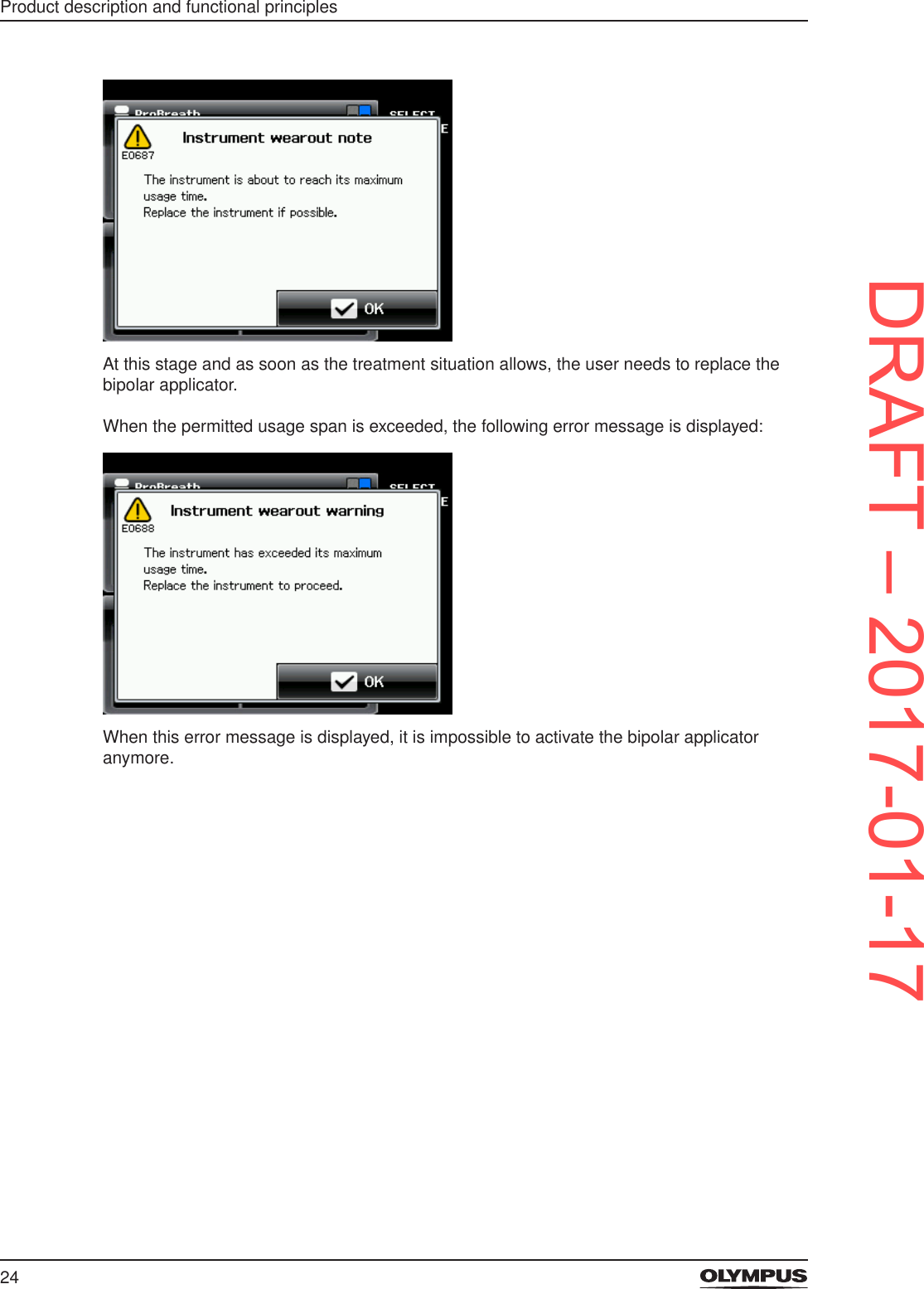
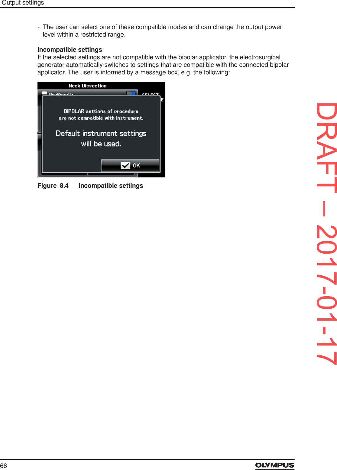
![23Product description and functional principles3.4.1 RFITT – Radiofrequency induced thermotherapyThe medical purpose of the radiofrequency induced thermotherapy, RFITT, is to achieve controlled tissue coagulation. The CELON ELITE ESG-200 offers 4 different RFITT modes that are used in conjunction with the CELON bipolar applicators. For further information refer to the section “The bipolar RFITT coagulation modes” on page 63.3.4.2 RCAP – Resistance Controlled Automatic Power for RFITTRCAP is a feature that supports the mode Strong RFITT. Deep tissue coagulation without signicant desiccation is achieved with RCAP.RCAP determines the maximum power uptake of the tissue, adapted to the momentary treatment status and automatically adjusts the electrosurgical generator. For this process, the geometry of the bipolar applicator used as well as individual tissue characteristics, e.g. blood perfusion, are taken into account. Therefore, premature tissue desiccation is effectively avoided and subsequent manual adjustment of the supplied power is unnecessary. Also refer to the section “The bipolar RFITT coagulation modes” on page 63.3.4.3 Automatic instrument recognitionThe electrosurgical generator is equipped with a radio transmitting and receiving technology. Therefore, the selected CELON bipolar applicator that is connected to the electrosurgical generator is recognized automatically. This means: - The name of the connected CELON bipolar applicator is displayed in the BIPOLAR pane of the touch screen, e. g. [ProBreath] or [ProSleep plus]. - Only compatible modes and output power settings are available. - The user can select one of these compatible modes and can change the output power level within a restricted range.Other radio transmitters and receivers, e. g. mobile phones, may interfere with the automatic instrument recognition. • To avoid interference observe the instructions in the chapter “Electromagnetic compatibility” on page 92.3.4.4 Automatic wear-out detectionTo protect the patient from a worn-out instrument the bipolar applicators are equipped with memory chips that record the usage. When the permitted usage span is nearly reached, the electrosurgical generator alerts the user by emitting an alarm tone and displaying the following error message:DRAFT – 2017-01-17](https://usermanual.wiki/Olympus-Winter-and-Ibe/ESG200.ESG200-UserMan-Celon-ELITE/User-Guide-3270684-Page-23.png)
![29Product description and functional principlesFigure 3.7 Buttons for system settingsSingle elements of the All ScreenFigure 3.8 Buttons and symbols on the All Screen1) Output socket indicator and output socket nameDisplays the symbol and the name of the corresponding output socket.2) Procedure nameDisplays the selected procedure. If no procedure is selected, then this line is blank.3) Autostart indicatorIndicates that the Autostart feature is assigned to the corresponding output socket.4) Button [SELECT PROCEDURE]To open the screen [Select Procedure screen] for recalling saved settings.5) Button [FOOT SWITCH]To open the screen [Assign Foot Switch] for assigning the foot switch or the Autostart feature to an output socket.6) Button [MENU]To open the screen [Select Menu] for controlling several functions.7) Foot switch indicatorIndicates that a foot switch is assigned to the corresponding output socket.DRAFT – 2017-01-17](https://usermanual.wiki/Olympus-Winter-and-Ibe/ESG200.ESG200-UserMan-Celon-ELITE/User-Guide-3270684-Page-29.png)
![30Product description and functional principles8) CQM indicator for neutral electrodesIndicates the connection status of a neutral electrode.9) Mode nameDisplays the selected mode.10) Output power levelDisplays the selected output power level.3.6.2 The Set ScreenOn the Set Screen the mode and the output power levels for the corresponding output socket are set. The Set Screen is displayed when tapping into the pane [BIPOLAR] or [MONOPOLAR] on the All Screen.Figure 3.9 Set Screen1) Mode buttonDisplays the name of the output mode as selected in the Mode Screen.2) Plus and minus buttonTo increase and decrease the level of output power.3) Return buttonTo save the settings and to return to the All Screen.4) Output power levelTo show the selected level of output power.DRAFT – 2017-01-17](https://usermanual.wiki/Olympus-Winter-and-Ibe/ESG200.ESG200-UserMan-Celon-ELITE/User-Guide-3270684-Page-30.png)
![31Product description and functional principles3.6.3 The Mode ScreenOn the Mode Screen the output mode is selected. The Mode Screen is displayed when tapping either the yellow area (cut) or blue area (coagulation) on the Set Screen.Figure 3.10 Mode Screen for monopolar cutting1) Mode buttonsTo select a mode for the corresponding output socket (BIPOLAR or MONOPOLAR).2) Button [Off]To completely deactivate cutting/coagulation for the output socket (BIPOLAR or MONOPOLAR).3) Return buttonTo return to the Set Screen.4) Arrow buttonsTo browse the pages of the Mode Screen.3.6.4 The screens for system settingsThe 3 buttons on the right-hand side of the All Screen give access to the settings of the following screens: - Select Procedure - Assign Foot Switch - Select MenuDRAFT – 2017-01-17](https://usermanual.wiki/Olympus-Winter-and-Ibe/ESG200.ESG200-UserMan-Celon-ELITE/User-Guide-3270684-Page-31.png)
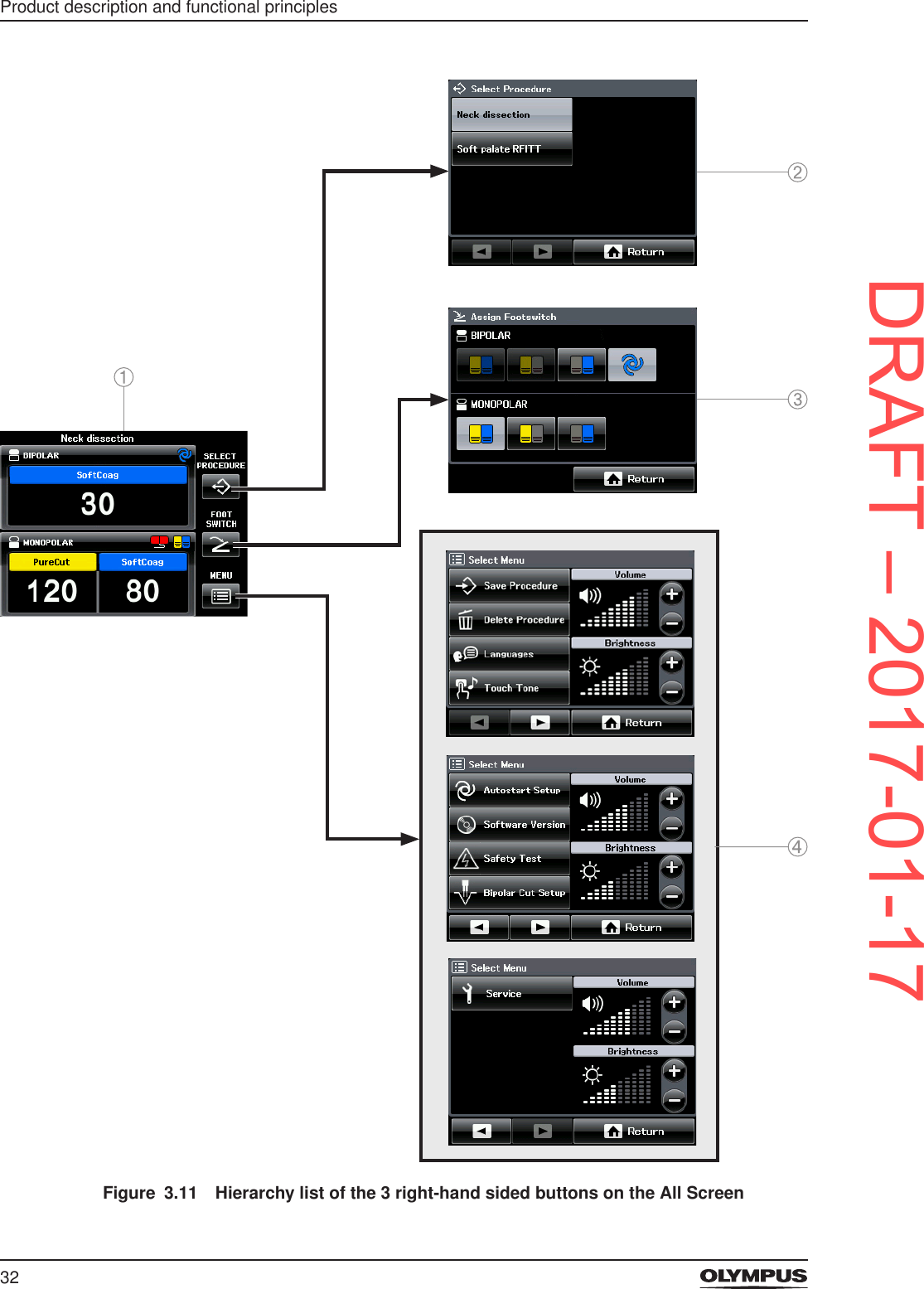
![33Product description and functional principles1) All Screen2) Screen [Select Procedure]3) Screen [Assign Foot Switch]4) Screen [Select Menu]For detailed information on system settings refer to the chapter “System settings” on page 39.3.6.5 Icons displayed on the touch screenSELECT PROCEDURE FOOT SWITCHMENU ReturnBIPOLAR output socket MONOPOLAR output socketNon-split type neutral electrode Split type neutral electrodeDouble pedal foot switch AutostartPlus MinusPrevious NextVolume BrightnessSave Procedure Delete procedureUpper case/lower case AlphabeticNumeric Back spaceLanguages Software versionTouch tone on Touch tone offSafety test ServiceBipolar cutting on Bipolar cutting offOK CancelCaution ResetTable: Icons displayed on the touch screenDRAFT – 2017-01-17](https://usermanual.wiki/Olympus-Winter-and-Ibe/ESG200.ESG200-UserMan-Celon-ELITE/User-Guide-3270684-Page-33.png)
![40System settingsButtons FunctionSELECT PROCEDURESelecting previously saved, preferred settings.FOOT SWITCHAssigning the foot switch and Autostart.MENU Save Procedure Saving or overwriting of output settings.Delete Procedure Deleting previously saved settings.Languages Selecting the preferred language.Available languages: English, Japanese, German, Chinese, French, Italian, Spanish and Portuguese.Touch Tone Activating or deactivating the audible feedback when tapping the touch screen.Autostart Setup Setting a time delay for Autostart.Software Version Showing information about the installed software version.Safety Test Opening or closing the output relays. Required for the annual safety check.Bipolar Cut Setup Switching the cutting modes for the BIPOLAR socket on or off.Service Accessing the service screen. For the technical service only. This screen is password protected.Volume control for output tone Increasing or decreasing of the volume of the output tone.Brightness control Increasing or decreasing of the brightness of the touch screen.Table: Overview of system settings5.3 Select Procedure settingsUse this function to select procedure settings that were saved previously.Figure 5.2 Screen [Select Procedure]There are no factory settings provided for this function. If no settings are saved, the message [No procedure saved] is displayed on the screen [Select Procedure]. Refer to the section “Save Procedure - Saving and overwriting procedure settings” on page 42.DRAFT – 2017-01-17](https://usermanual.wiki/Olympus-Winter-and-Ibe/ESG200.ESG200-UserMan-Celon-ELITE/User-Guide-3270684-Page-40.png)
![41System settingsTo select one of the saved procedure settings proceed as follows:1. Tap [SELECT PROCEDURE] on the All Screen. - The screen [Select Procedure] is displayed with a list of saved procedure settings. - An already selected procedure is indicated by a highlighted button. - If no procedure settings are saved, the message [No procedure saved] is displayed. • To return to the All Screen tap [Return].2. Tap the button of the procedure to be selected. - The All Screen is displayed which shows the settings of the selected procedure. - In the headline of the All Screen the name of the selected procedure is displayed.5.4 Foot switch assignment and AutostartFoot switch pedalsUse this function to assign the double pedal foot switch either to the BIPOLAR output socket or to the MONOPOLAR output socket. It is also possible to assign one pedal of the foot switch to the BIPOLAR output socket and the other pedal to the MONOPOLAR output socket.As a default setting the cutting modes for the BIPOLAR socket are switched off. Therefore, it is impossible to assign the yellow cut pedal to the BIPOLAR socket. • To switch on the bipolar cutting modes refer to the section “Bipolar Cut Setup” on page 46.Figure 5.3 Screen [Assign Foot Switch]Autostart and time delayFor the bipolar mode SoftCoag the feature Autostart can be assigned to the BIPOLAR output socket. Refer to the sections “Autostart for the bipolar mode SoftCoag” on page 22 and “Autostart Setup” on page 45.Highlighted buttonsThe chosen assignments are indicated by highlighted buttons. The gure above shows that Autostart is assigned to the BIPOLAR output socket. To the MONOPOLAR output socket, both pedals of the foot switch are assigned. If the foot switch is not connected properly, then no button is highlighted and it is impossible to assign the foot switch or Autostart.To assign the foot switch or Autostart to the output sockets proceed as follows:1. Tap [FOOT SWITCH] on the All Screen.DRAFT – 2017-01-17](https://usermanual.wiki/Olympus-Winter-and-Ibe/ESG200.ESG200-UserMan-Celon-ELITE/User-Guide-3270684-Page-41.png)
![42System settingsThe screen [Assign Foot Switch] is displayed.2. In the BIPOLAR pane of the screen tap the button for the required function, i.e. double pedal, only yellow pedal, only blue pedal or Autostart.3. In the MONOPOLAR pane tap the button for the required foot switch, i.e. double pedal, only yellow pedal or only blue pedal.4. Tap [Return] to conrm the settings.The All Screen is displayed.Limited power for AutostartIf the output power level is above 50 when selecting Autostart, then the output power level is reduced to 50 automatically.5.5 Select Menu settingsUse this function to adjust the menu settings as summarized in the table “Overview of system settings” on page 39.Figure 5.4 Screen [Select Menu]When opening the screen [Select Menu] there are 2 arrow buttons at the bottom.1. Tap [MENU] on the All Screen.The screen [Select Menu] is displayed.2. Use the arrow buttons to browse back and forth between the pages of the screen [Select Menu].Cancel buttonFor most of the following menu settings it is possible to interrupt the operation by tapping [Cancel] until the screen [Select Menu] is displayed again.5.5.1 Save Procedure - Saving and overwriting procedure settingsThe delay for Autostart cannot be saved within a procedure setting.Use this function to save all output settings that are currently displayed on the All Screen under a certain procedure name. In detail this is: - The bipolar modes for cutting and coagulation and their output levels. - The monopolar modes for cutting and coagulation and their output levels. - The assignment of the foot switch or Autostart for the bipolar mode SoftCoag.It is possible to save up to 39 different procedure settings and to overwrite existing settings.DRAFT – 2017-01-17](https://usermanual.wiki/Olympus-Winter-and-Ibe/ESG200.ESG200-UserMan-Celon-ELITE/User-Guide-3270684-Page-42.png)
![43System settingsThe onscreen keyboardFigure 5.5 Onscreen keyboard (letters and numbers) • To switch between letters and numbers tap [123] or [ABC] at the bottom of the keyboard.Figure 5.6 Onscreen keyboard (upper/lower key and backspace key) • To switch between upper-case letters and lower-case letters tap the shift key at the bottom left of the keyboard. • To delete characters tap the backspace key on the bottom right of the keyboard.Saving a new procedure settingTo save the current output settings proceed as follows:1. Tap [MENU] on the All Screen.The screen [Select Menu] is displayed.2. Tap [Save Procedure].The screen [Save Procedure] is displayed.3. Tap [New Procedure].The screen changes to an onscreen keyboard.4. Enter a name for the procedure setting.5. Tap [OK] to save the procedure name. - A message box is displayed which conrms that the procedure settings are saved. - Then the All Screen is displayed. - In the headline of the All Screen the procedure name is displayed.If a procedure name already exists, then a message box is displayed that asks for conrmation to overwrite the existing procedure settings. Refer to the section below.DRAFT – 2017-01-17](https://usermanual.wiki/Olympus-Winter-and-Ibe/ESG200.ESG200-UserMan-Celon-ELITE/User-Guide-3270684-Page-43.png)
![44System settingsOverwriting a procedure setting1. Tap [MENU] on the All Screen.The screen [Select Menu] is displayed.2. Tap [Save Procedure].The screen [Save Procedure] is displayed.3. Use the arrow buttons to browse back and forth the pages of the screen.4. Tap the name of the procedure settings to be overwritten.A message box with a request for conrmation is displayed.5. To overwrite the existing procedure settings tap [OK] in the message box. - Another message box is displayed which conrms that the procedure settings are saved. - Then the All Screen is displayed.5.5.2 Delete ProcedureTo delete an existing procedure setting from the memory proceed as follows:1. Tap [MENU] on the All Screen.The screen [Select Menu] is displayed.2. Tap [Delete Procedure].The screen [Delete Procedure] is displayed.3. Use the arrow buttons to browse back and forth the pages of the screen.4. Tap the procedure name of the settings to be deleted.A message box with a request for conrmation is displayed.5. Tap [OK] to delete the procedure settings. - Another message box is displayed which conrms that the procedure settings are deleted. - Then the screen [Select Menu] is displayed.5.5.3 LanguagesUse the language function to select the preferred language. The text on the touch screen can be displayed in 8 different languages: - English - German - French - Italian - Japanese - Chinese - Spanish - PortugueseTo select the preferred language proceed as follows:1. Tap [MENU] on the All Screen.The screen [Select Menu] is displayed.2. Tap [Languages]. - The screen [Select Language] is displayed. - The language currently selected is highlighted.3. Tap the button of the preferred language.A message box with a request for conrmation is displayed.4. Tap [OK] to change the language setting. - The language is changed. - Then the screen [Select Menu] is displayed.DRAFT – 2017-01-17](https://usermanual.wiki/Olympus-Winter-and-Ibe/ESG200.ESG200-UserMan-Celon-ELITE/User-Guide-3270684-Page-44.png)
![45System settings5.5.4 Touch ToneUse this function to turn on or off the audible feedback when tapping the touch screen. As a default setting the audible feedback is turned off.To turn the audible feedback on or off proceed as follows:1. Tap [MENU] on the All Screen.The screen [Select Menu] is displayed.2. Tap [Touch Tone]. - The screen [Touch Tone] is displayed. - The current setting is highlighted.3. Tap [On] or [Off] to turn the touch tone on or off.The selected choice is highlighted.4. Tap [OK].The screen [Select Menu] is displayed.5.5.5 Autostart SetupUse this function to set a time delay for the feature Autostart. With a time delay the electrosurgical generator does not activate immediately when the HF instrument touches the tissue but waits until the specied time has expired.The time delay is specied in seconds. It is possible to enter a value between 0.0 and 9.9 seconds. The default setting is 1.0 s. - The Autostart feature is available only for the bipolar coagulation mode SoftCoag. - Precondition: The Autostart feature is assigned to the BIPOLAR output socket. Refer to section “Foot switch assignment and Autostart” on page 41.To set the time delay for the Autostart feature proceed as follows:1. Tap [MENU] on the All Screen.The screen [Select Menu] is displayed.2. Tap the arrow button [Next] to browse to the next page of the screen [Select Menu].3. Tap [Autostart Setup]. - The screen [Autostart Setup] is displayed. - The current time delay is displayed in seconds.4. Tap [+] or [−] to modify the current setting.5. Tap [OK] to save the current setting.The screen [Select Menu] is displayed.5.5.6 Software VersionThis function displays the currently installed software version of the electrosurgical generator.To display the software version proceed as follows:1. Tap [MENU] on the All Screen.The screen [Select Menu] is displayed.2. Tap the arrow button [Next] to browse to the next page of the screen [Select Menu].3. Tap [Software Version].The currently installed software version is displayed.4. Tap [OK] to return to the screen [Select Menu].DRAFT – 2017-01-17](https://usermanual.wiki/Olympus-Winter-and-Ibe/ESG200.ESG200-UserMan-Celon-ELITE/User-Guide-3270684-Page-45.png)
![46System settings5.5.7 Safety TestThis function is required for the annual safety check. Refer to the chapter “Maintenance, repair and shipment” on page 86. This function is used to close the output relays which disables the electrosurgical generator for normal operation. Closed output relays are needed to perform measurements. - The default setting is [Relays Off]:The relays are open and the electrosurgical generator is enabled for normal operation. - The setting [Relays On]:The relays are closed. The electrosurgical generator is disabled for normal operation.As soon as the user exits this menu function, the relay setting is automatically set to default, i.e. normal operation of the electrosurgical generator.To open or close the output relays proceed as follows:1. Tap [MENU] on the All Screen.The screen [Select Menu] is displayed.2. Tap the arrow button [Next] to browse to the next page of the screen [Select Menu].3. Tap [Safety Test]. - The screen [Safety Test] is displayed. - The current setting is highlighted.4. Tap [Relays On] or [Relays Off].The new setting is highlighted.5. Tap [Cancel] to return to the screen [Select Menu].5.5.8 Bipolar Cut SetupThe electrosurgical generator provides the options to switch the bipolar cutting modes on or off. If the bipolar cutting modes are switched on, the BIPOLAR pane is divided into a yellow button for cutting and a blue button for coagulation. The user can access and activate all bipolar cutting modes.As a default setting the cutting modes for the BIPOLAR socket are switched off, i.e. only the blue coagulation button is displayed in the BIPOLAR pane. It is impossible to access and activate any bipolar cutting mode.To switch the bipolar cutting modes on or off proceed as follows:1. Tap [MENU] on the All Screen.The screen [Select Menu] is displayed.2. Tap the arrow button [Next] to browse to the next page of the screen [Select Menu].3. Tap [Bipolar Cut Setup]. - The screen [Bipolar Cut Setup] is displayed. - The current setting is highlighted.4. Tap [On] or [Off].The new setting is highlighted.5. Tap [OK] to return to the screen [Select Menu].5.5.9 ServiceThis function is not intended for customer use. It is password protected and only accessible for authorized service centers.DRAFT – 2017-01-17](https://usermanual.wiki/Olympus-Winter-and-Ibe/ESG200.ESG200-UserMan-Celon-ELITE/User-Guide-3270684-Page-46.png)
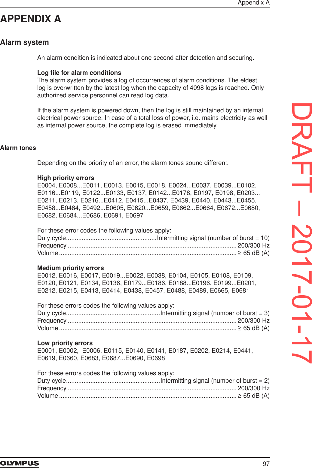
![47System settings5.5.10 Volume controlWARNINGThe output tones play an important role to notice the output power when the electrosurgical generator is activated. If the output tones are inaudible, then activation may not be recognized by the user. This could result in injury to the patient. • Make sure that the output tones are at an audible volume level. • Adjust the volume level of the output tones to the ambient noises.The volume of the output tone can be adjusted either with the volume control on the rear panel of the electrosurgical generator or via touch screen. However, during activation, it is impossible to enter the screen [Select Menu]. Therefore, the volume needs to be adjusted with the volume control at the rear panel during activation.The volume settings range from 1 to 10. The default setting is 7.To set the volume for the output tone via the touch screen proceed as follows:1. Tap [MENU] on the All Screen.The screen [Select Menu] is displayed.Figure 5.7 Volume control2. In the volume pane tap [+] to increase the volume. Tap [−] to decrease the volume of the output tone.Volume of error tonesThe volume of the error tones (low, medium and high priority errors) are not adjustable. Refer to the chapter “Troubleshooting” on page 78 and to the sections “Alarm system” on page 97 and “Output tone information” on page 98in the Appendix A.5.5.11 Brightness controlUse this function to control the brightness of the touch screen. The brightness settings range from 1 to 10. The default setting is 5.To set the brightness proceed as follows:1. Tap [MENU] on the All Screen.The screen [Select Menu] is displayed.DRAFT – 2017-01-17](https://usermanual.wiki/Olympus-Winter-and-Ibe/ESG200.ESG200-UserMan-Celon-ELITE/User-Guide-3270684-Page-47.png)
![48System settingsFigure 5.8 Brightness control2. In the brightness pane tap [+] to increase the brightness. Tap [−] to decrease the brightness of the touch screen.DRAFT – 2017-01-17](https://usermanual.wiki/Olympus-Winter-and-Ibe/ESG200.ESG200-UserMan-Celon-ELITE/User-Guide-3270684-Page-48.png)


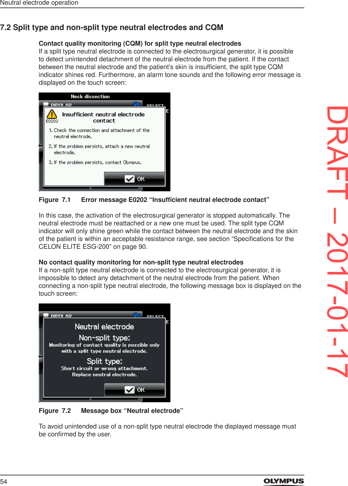
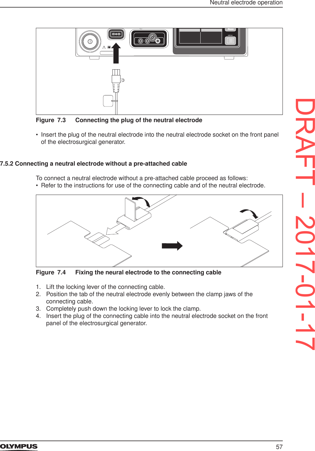
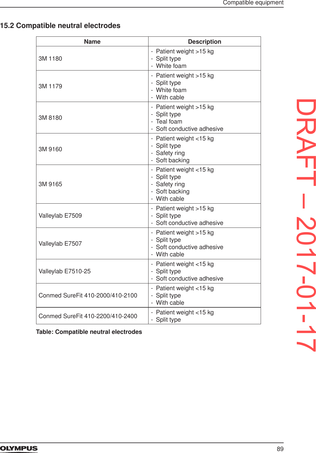
![55Neutral electrode operationThe CQM indicator for non-split type neutral electrodes shines green if a non-split type neutral electrode is detected.7.3 Meaning of CQM indicator conditionThe CQM indicator can take on the following conditions:Indicator for split type neutral electrodes shines green - CQM detects a split type neutral electrode. - Sufcient contact between the neutral electrode and the patient’s skin. - Activation is possible. • Continue with the procedure.Indicator for split type neutral electrodes shines redDuring activation: During standby:1) Insufcient contact between the neutral electrode and the patient’s skin.2) The connection between the neutral electrode and the electrosurgical generator is interrupted. - Activation stops automatically. - An alarm tone sounds and the error message E0202 “Insufcent neutral electrode contact” is displayed. • Follow the instructions given in the error message.1) No neutral electrode connected.2) Insufcient contact between the neutral electrode and the patient’s skin. - Activation is disabled. Indicator for non-split type neutral electrodes shines green If a split type neutral electrode is connected:If a non-split type neutral electrode is connected:1) CQM cannot detect the split type neutral electrode.2) The split type neutral electrode has a short circuit. - The message box “Neutral electrode” (Figure 7.2) is displayed. • Tap [OK] to conrm the message. • Replace the split type neutral electrode.1) CQM detects a non-split type neutral electrode. - Activation is possible. • Continue with the procedure.7.4 Correct usage of neutral electrodesFor the safe use of neutral electrodes refer to the instructions for use of the correspondent neutral electrode and take account of the following:Compatible neutral electrodesThe section “Compatible neutral electrodes” on page 89 lists different neutral electrodes that are compatible for the use with the electrosurgical generator.DRAFT – 2017-01-17](https://usermanual.wiki/Olympus-Winter-and-Ibe/ESG200.ESG200-UserMan-Celon-ELITE/User-Guide-3270684-Page-55.png)

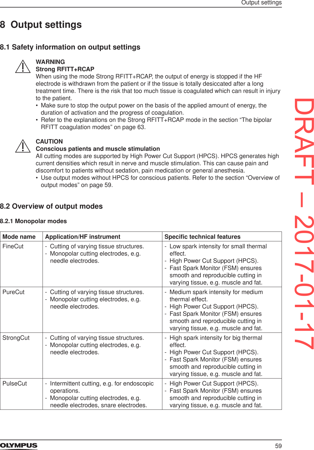
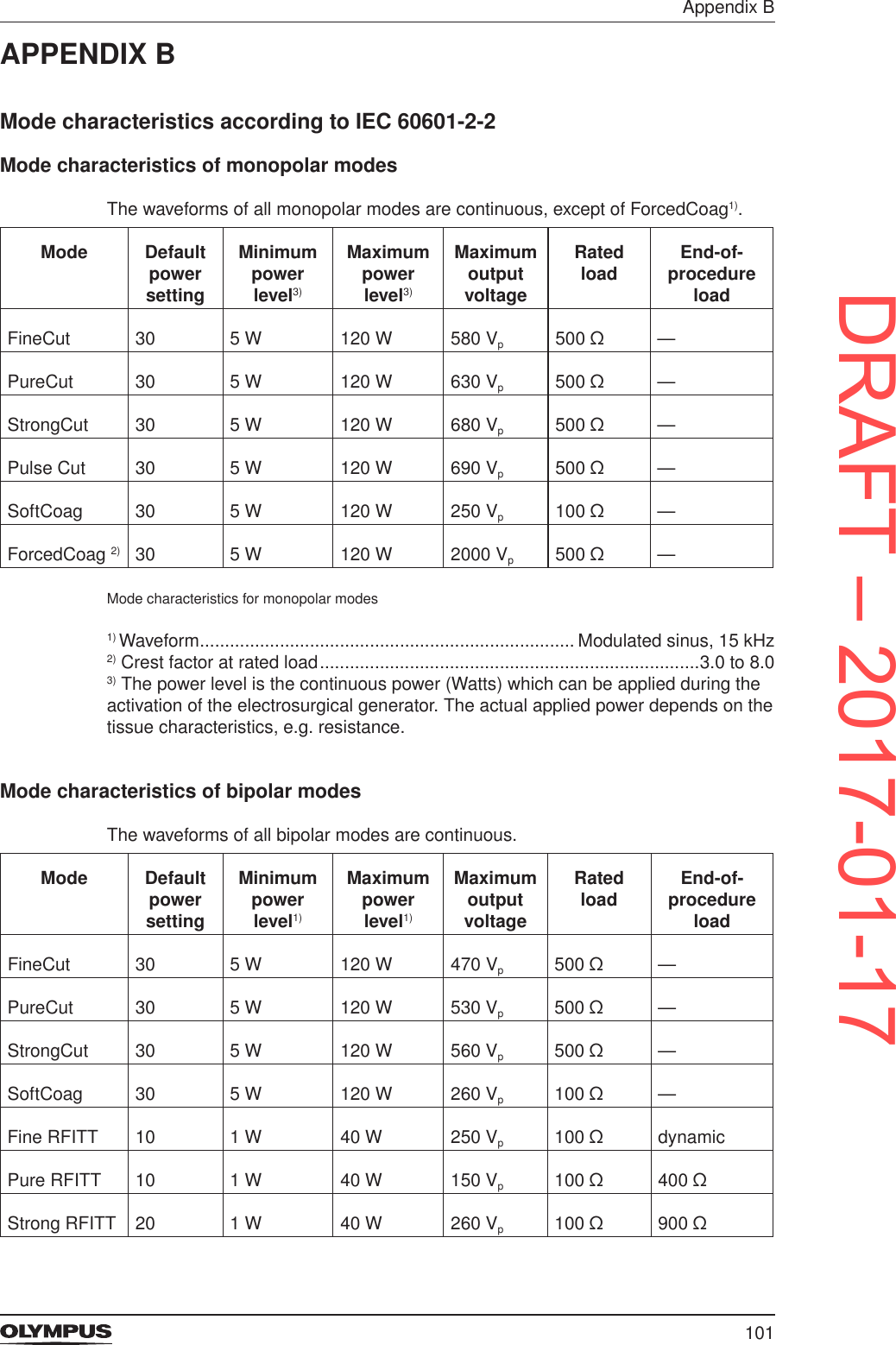
![62 Output settingsMode name Effect on tissue Strong RFITT +RCAPIf the output power level is below the optimum power level: - Increasing the output power level results in an increased coagulation depth. - Decreasing the output power level results in a decreased coagulation depth.If the output power level is above the optimum power level: - Increasing and decreasing the output power level does not result in a signicant change of coagulation depth because of RCAP. • Refer to the section “The bipolar RFITT coagulation modes” on page 63.Table: Tissue effects depending on output power level in bipolar modes8.4 Selecting the appropriate output settingsAppropriate selections • Select a mode according to the type of procedure that will be performed and according to the HF instruments that will be used. • For details on the applications, HF instruments and specic technical features of the different modes and for the impact of output power levels refer to the section “Overview of output modes” on page 59.Output power level and applied powerThe output power levels that are displayed on the All Screen or on the Set Screen represent the maximum possible output power levels in watts. The actually applied power depends on the tissue characteristics, e.g. resistance.Minimum output power levelIf the output power level of a mode is set below the minimum allowed value by the user, then the electrosurgical generator automatically sets the output power level to 0. Instead of a number for the output power level, [--] is displayed. Each mode has specic minimum output power levels. Refer to the section “Mode characteristics according to IEC 60601-2-2” on page 101 in the Appendix B. It is impossible to change the mode or the output power level during activation.Selecting the settings on the touch screenTo set the required output settings proceed as follows:Figure 8.6 All ScreenDRAFT – 2017-01-17](https://usermanual.wiki/Olympus-Winter-and-Ibe/ESG200.ESG200-UserMan-Celon-ELITE/User-Guide-3270684-Page-62.png)
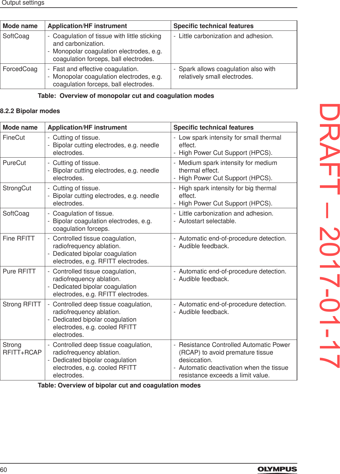
![63 Output settings1. On the All Screen tap into the pane for the required output socket, i.e. either [MONOPOLAR] or [BIPOLAR].The Set Screen is displayed.Figure 8.7 Set Screen for monopolar modes2. Tap the yellow button for selecting a cutting mode or tap the blue button for selecting a coagulation mode.The Mode Screen is displayed. The currently selected mode is highlighted.Figure 8.8 Mode Screen for monopolar cutting modes3. Tap the button of the required mode, e.g. [FineCut].The display changes back to the Set Screen and shows the chosen mode.4. Increase or decrease the output power level by tapping [+] or [−] of the chosen mode.Tapping [Off] on the Mode Screen completely deactivates cutting or coagulation for this output socket. Then, instead of a number for the output power level, [--] is displayed.8.5 The bipolar RFITT coagulation modesThe medical purpose of the radiofrequency induced thermotherapy (RFITT) is to achieve controlled tissue coagulation. The electrosurgical generator offers 4 different RFITT modes as mentioned in the table above.One of these modes also offers Resistance Controlled Automatic Power (RCAP) which is explained further below.DRAFT – 2017-01-17](https://usermanual.wiki/Olympus-Winter-and-Ibe/ESG200.ESG200-UserMan-Celon-ELITE/User-Guide-3270684-Page-63.png)
![64 Output settingsThe RFITT modes are available only for selected CELON bipolar applicators, e.g. CelonProSleep plus or CelonProBreath.RFITT modes without RCAPDuring activation, the electrosurgical generator provides audible feedback of the coagulation status. The frequency of the output tone is proportional to the tissue resistance at any particular moment. As the measured tissue resistance increases, the frequency of the output tone also increases. This permits audible monitoring of the coagulation status since the latter is directly connected with the tissue resistance.Energy is applied until the tissue resistance exceeds a limit value, i.e. automatic end-of-procedure detection. Then the power output is automatically stopped (for the modes Fine RFITT, Strong RFITT) or reduced to a minimum (Pure RFITT), because the coagulation process is completed due to desiccation of the tissue. This is indicated by an intermittent audible signal.Detailed information on output limits and output characteristics are given in the “Appendix A” on page 97.Strong RFITT+RCAPThe medical purpose of the mode Strong RFITT+RCAP is to achieve deep tissue coagulation without signicant tissue desiccation.Once the tissue resistance increases signicantly, which indicates beginning tissue desiccation, the electrosurgical generator reduces the power automatically. This enables the tissue to rehydrate, resulting in normal electrical resistance of the tissue after a few seconds. Detecting this decrease of resistance, the electrosurgical generator automatically increases the power again to the preset level and continues the heating process. This cycle is repeated until the user stops the activation or until the tissue resistance exceeds a limit value. In the latter case, the power output is automatically stopped, which is indicated by an intermittent audible signal.Application time and energy counter for RFITT modesFigure 8.1 Counters on the Set Screen and during activationOn the Set Screens of RFITT modes an application time counter and an energy counter are displayed. The counters indicate previous treatment parameters. During activation of the electrosurgical generator these counters are constantly updated. - The application time counter shows the total application duration of output power in minutes and seconds in the format [00:00].After 999 minutes and 59 seconds the application time counter starts counting from 0.DRAFT – 2017-01-17](https://usermanual.wiki/Olympus-Winter-and-Ibe/ESG200.ESG200-UserMan-Celon-ELITE/User-Guide-3270684-Page-64.png)
![65 Output settings - The energy counter shows the total amount of energy emitted in kilojoules in the following formats: - [0.00 kJ] for up to 9.99 kJ - [00.0 kJ] for up to 99.9 kJ - [000 kJ ] for up to 999 kJ - When exceeding an energy amount of 999 kJ the electrosurgical generator continues to count in Megajoules (MJ). • To reset the counters to 0 either switch off the electrosurgical generator or tap [Reset] on the Set Screen.To avoid patient injury and damage of bipolar RFITT applicators by unintended activation of bipolar cutting, no bipolar cutting mode can be activated while a RFITT mode is selected. If the yellow cut pedal is pressed by mistake then the following error message is displayed:Figure 8.2 Error message E0660 “No bipolar cutting”8.6 Output settings for selected CELON bipolar applicatorsFigure 8.3 Automatic instrument recognitionThe electrosurgical generator recognizes the CELON bipolar applicator that is connected. This means: - The name of the connected CELON bipolar applicator is displayed in the BIPOLAR pane of the touch screen, e. g. [ProBreath]. - Only compatible modes and output power settings are available.DRAFT – 2017-01-17](https://usermanual.wiki/Olympus-Winter-and-Ibe/ESG200.ESG200-UserMan-Celon-ELITE/User-Guide-3270684-Page-65.png)
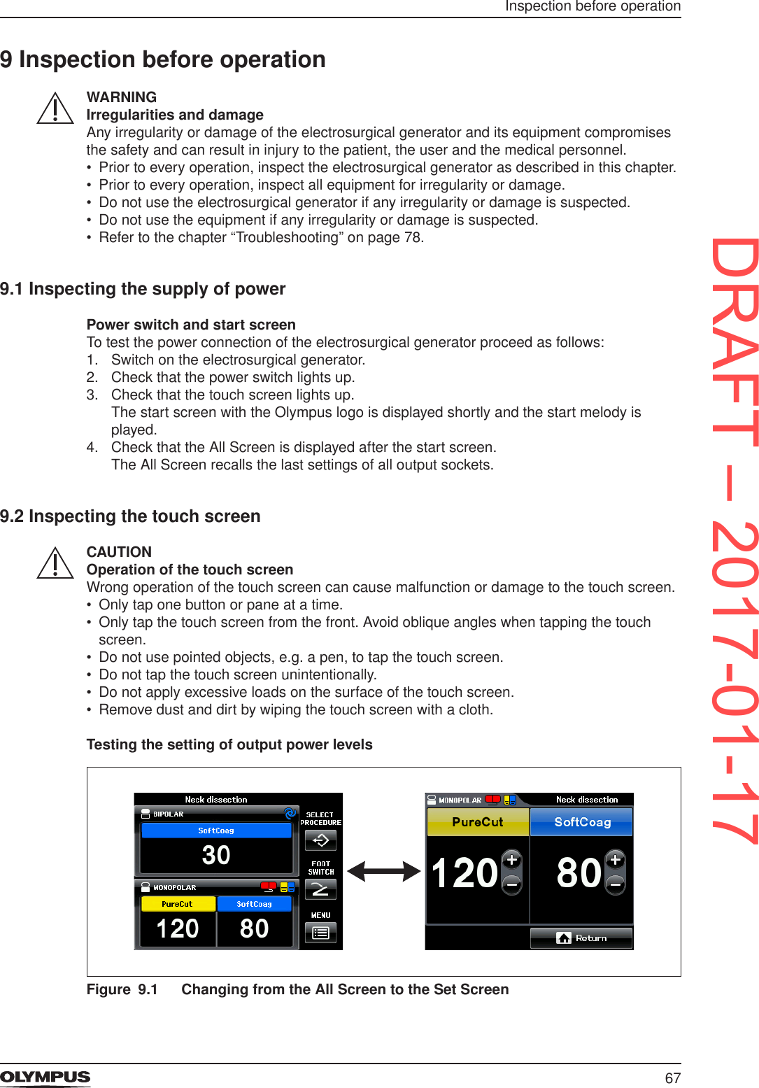
![68Inspection before operationTo test the functionality of the output power settings proceed as follows:1. Tap into the pane [MONOPOLAR].Check that the screen changes from the All Screen to the Set Screen, displaying the settings of the MONOPOLAR output socket.2. Test the plus buttons by tapping [+].For values up to 50 the output power level increases in steps of 1 per tap.For values above 50 the plower level increases in steps of 5 per tap.3. Test the minus buttons by tapping [−].For values up to 50 the output power level decreases in steps of 1 per tap.For values above 50 the plower level decreases in steps of 5 per tap.4. Touch and hold [+] and then [−] to check that the output power level increases/decreases fast.5. Tap [Return] to return to the All Screen.Testing the screen [Select Menu]Figure 9.2 Changing from the All Screen to the screen [Select Menu]To test the functionality of the screen [Select Menu] proceed as follows:1. Tap [MENU] on the All Screen.Check that the screen changes from the All Screen to the screen [Select Menu].2. Tap [Return] to return to the All Screen.9.3 Inspecting the foot switch assignmentFigure 9.3 Changing from the All Screen to the screen [Assign Foot Switch]To test the functionality for the foot switch assignment proceed as follows:1. Tap [FOOT SWITCH] on the All Screen.DRAFT – 2017-01-17](https://usermanual.wiki/Olympus-Winter-and-Ibe/ESG200.ESG200-UserMan-Celon-ELITE/User-Guide-3270684-Page-68.png)
![69Inspection before operationThe screen changes from the All Screen to the screen [Assign Foot Switch].2. In the MONOPOLAR pane tap the button [double pedal foot switch].Check that this button is highlighted.3. Disconnect the foot switch plug from the electrosurgical generator.Check that no foot switch buttons are highlighted anymore.4. Tap [Return] to return to the All Screen.9.4 Inspecting the alarm systemThis section describes how to test the functionality of the neutral electrode alarm substitutionally for the whole alarm system.WARNINGAlarm functionIf the alarm function is not normal, the electrosurgical generator might fail to detect an equipment error. This may result in unexpected burns, perforation or bleeding. • Inspect the alarm function before each use.Neutral electrode warningFigure 9.4 Error message E0202 “Insufcient neutral electrode contact”To test the functionality of the neutral electrode alarm proceed as follows:1. Make sure that no neutral electrode is connected to the electrosurgical generator.2. Check that the contact quality monitor indicator shines red.3. Try to activate any monopolar mode by pressing the corresponding foot switch pedal. • Check that the output power cannot be activated. • Check that the error message E0202 is displayed and that an alarm tone sounds. • Check that the alarm tone stops and that the error message E0202 is closed after approximately 10 seconds.DRAFT – 2017-01-17](https://usermanual.wiki/Olympus-Winter-and-Ibe/ESG200.ESG200-UserMan-Celon-ELITE/User-Guide-3270684-Page-69.png)
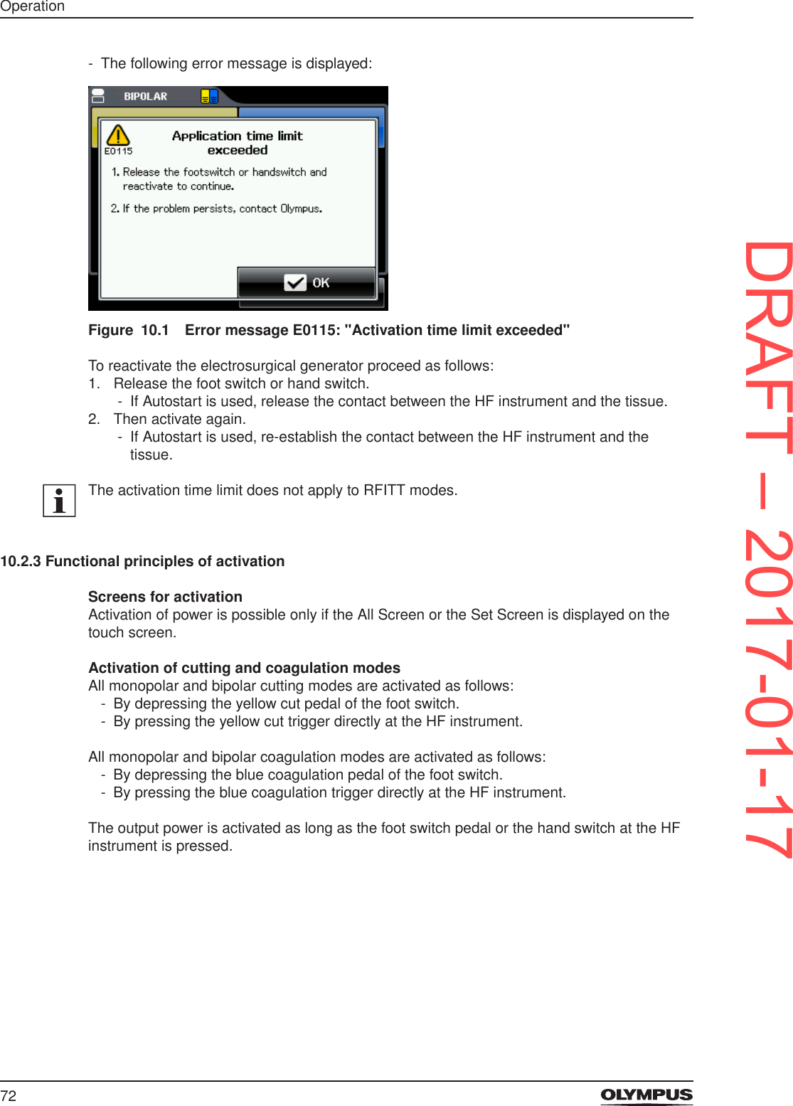
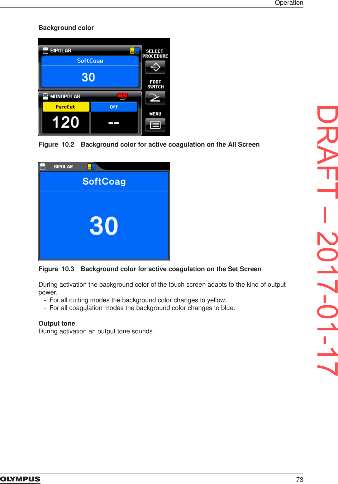
![74OperationWhen attempting to activate although the output power level is set to 0, then an alarm tone sounds and the following error message is displayed:Figure 10.4 Error message E0141 "Power set to zero (--)" • Conrm the message by tapping [OK] or wait for a few seconds and then continue.Activation with Autostart for bipolar SoftCoagThe bipolar SoftCoag mode can be activated via Autostart if this is assigned to the corresponding output socket. • Refer to the section “Autostart for the bipolar mode SoftCoag” on page 22 for more details on the Autostart feature. • Refer to the section “Foot switch assignment and Autostart” on page 41 for instructions on assigning Autostart. • Refer to the section “Autostart Setup” on page 45 for instructions on setting a time delay to Autostart.Stopping activationThe output of power stops as soon the foot switch pedal or the hand switch is released.When using Autostart for the bipolar mode SoftCoag, the output of power stops as soon as the HF instrument is removed from the tissue.10.3 After useAfter each use, immediately perform the procedures as described in the following paragraphs. If cleaning is delayed, debris encrustation may become a source of infection. Encrustation may also result in malfunction of the electrosurgical generator.WARNINGProtective clothing for cleaning and disinfectionTissue debris and reprocessing chemicals represent a risk of infection for the reprocessing personnel. • During cleaning and disinfection wear appropriate personal protective clothing such as eye wear, face mask, moisture-resistant clothing and surgical gloves that t properly. • Before leaving the reprocessing area, remove the contaminated protective clothing.WARNINGDryingIf the electrosurgical generator is stored or used after cleaning while still damp, then this can result to electric shock to the patient and the user.DRAFT – 2017-01-17](https://usermanual.wiki/Olympus-Winter-and-Ibe/ESG200.ESG200-UserMan-Celon-ELITE/User-Guide-3270684-Page-74.png)
![78Troubleshooting12 Troubleshooting • If the problem cannot be resolved by the described remedial actions, stop using the electrosurgical generator and contact Olympus. • Be aware that repairs may only be performed by authorized service centers.12.1 General problemsCheck the following table to identify and correct failures. If the problem cannot be resolved by the described remedial actions, contact Olympus.Problem Cause RemedyThe electrosurgical generator does not respond when pressing the power switch.Improper connection of the cord set to the socket on the rear panel of the electrosurgical generator or to the grounded mains electricity socket.Check the cord set and the grounded xed socket-outlet for correct connection.The grounded xed socket-outlet has wrong or no output voltage.Check the grounded xed socket-outlet or use an alternative grounded xed socket-outlet.The cord set is damaged. Check the cord set for damages and, if necessary, replace the cord set.Malfunction of the electrosurgical generator.Do not use this electrosurgical generator.Contact Olympus.After switching on the electrosurgical generator the touch screen remains dark but sounds are audible.Malfunction of the touch screen. Do not use this electrosurgical generator.Contact Olympus.The touch screen cannot be controlled.An object is in contact with the touch screen.Remove the object.Malfunction of the touch screen. Do not use this electrosurgical generator.Contact Olympus.There is no sound coming from the electrosurgical generator during activation.The volume for the output tone is set to an inaudible level, e.g. due to high environmental noise.Increase the volume either on the screen [Select Menu] or use the volume control on the rear panel of the electrosurgical generator.Malfunction of the electrosurgical generator.Do not use this electrosurgical generator.Contact Olympus.The volume cannot be adjusted on the screen [Select Menu] or via the volume control on the rear panel of the electrosurgical generator.The volume of error-related alarm tones is not adjustable.No action required.Malfunction of the electrosurgical generator.Do not use this electrosurgical generator.Contact Olympus.DRAFT – 2017-01-17](https://usermanual.wiki/Olympus-Winter-and-Ibe/ESG200.ESG200-UserMan-Celon-ELITE/User-Guide-3270684-Page-78.png)
![79TroubleshootingProblem Cause RemedyThe electrosurgical generator does not respond to foot switch or hand switch activation.Improper contact of the connection cable of the foot switch or the HF instrument to the corresponding socket of the electrosurgical generator.Check the connection cable of the foot switch and the HF instrument for correct connection.The foot switch, the hand switch of the HF instrument or their connection cables are damaged.Observe the foot switch, the hand switch of the HF instrument and their connection cables for damages. If necessary, replace the foot switch, the HF instrument or the corresponding connection cable.The wrong foot switch pedal or the wrong hand switch is pressed.Press the correct foot switch pedal or the correct hand switch of the HF instrument.The electrosurgical generator is not switched on.Switch on the electrosurgical generator with the power switch.2 switches for activating the output power are pressed simultaneously, e.g. another foot switch pedal or hand switch of an HF instrument.Release all switches for activation and check that no switch is pressed unintentionally. Then activate the output power using only 1 switch.A message box is displayed on the touch screen.Tap [OK] or [Cancel] to close the message box or wait until the message box closes automatically after a few seconds.It is possible to activate the output power only if either the All Screen or the Set Screen is displayed on the touch screen.Return to the All Screen or the Set Screen.The output mode is deactivated ([Off] is displayed) or the output power level is set to 0 ([--] is displayed).Activate the output mode on the Mode Screen or increase the output power level on the Set Screen. Refer to the section “Selecting the appropriate output settings” on page 62.Malfunction of the electrosurgical generator.Do not use this electrosurgical generator.Contact Olympus.Autostart is selected and the HF instrument has contact with the tissue, but the electrosurgical generator does not activate.A long time delay for Autostart is set. Reduce the time delay for Autostart. Refer to the section “Autostart Setup” on page 45.Malfunction of the electrosurgical generator.Do not use this electrosurgical generator.Contact Olympus.DRAFT – 2017-01-17](https://usermanual.wiki/Olympus-Winter-and-Ibe/ESG200.ESG200-UserMan-Celon-ELITE/User-Guide-3270684-Page-79.png)
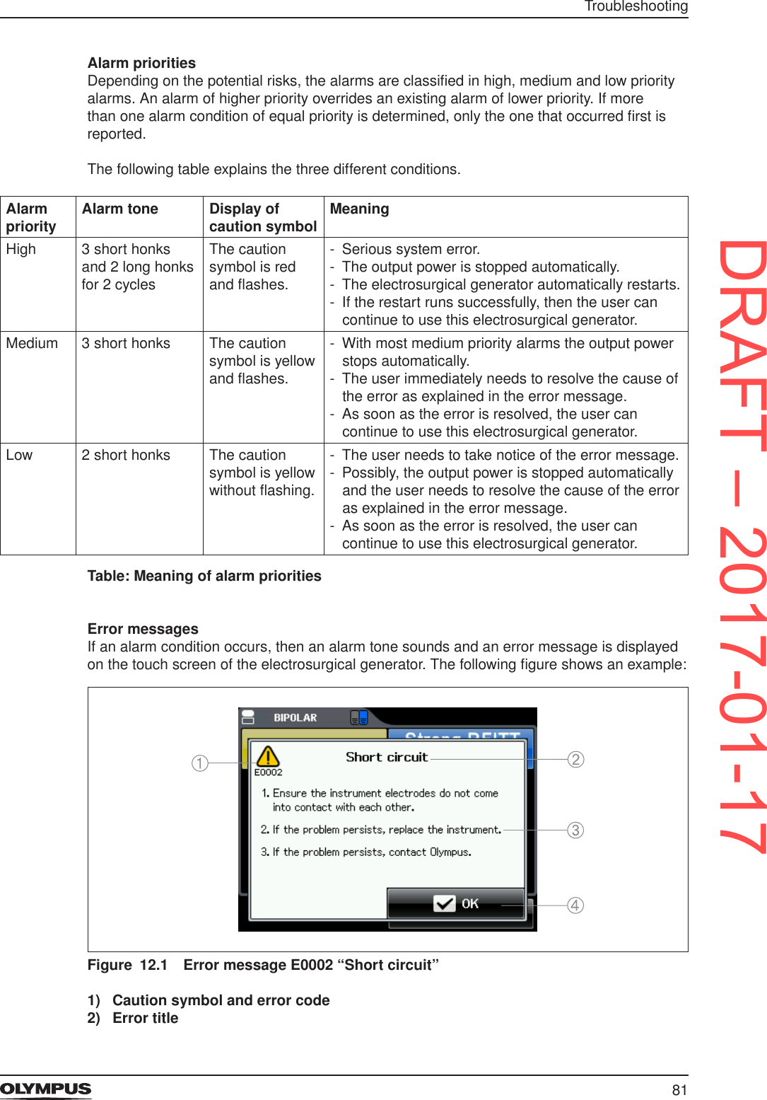
![82Troubleshooting3) Remedial actions4) Conrmation buttonIf the cause that released the alarm is cleared, then the error message is closed automatically after approximately 10 seconds. If the cause of the alarm is not cleared, then the error message stays on the touch screen. • To clear the alarm, follow the instructions that are given in the error message.It is possible to tap [OK] in the error message to close the error message faster.12.2.1 Overview of error messagesThe following table gives an overview of all error messages that possibly can be displayed. The error messages are sorted numerically according to the error code.Error code Message Cause Remedial actionE0001 Open circuit1. Check if the electrodes of the instrument have proper tissue contact.2. If the problem persists, replace the instrument.3. If the problem persists, contact Olympus.The electrodes of the HF instrument have no tissue contact.Ensure that the electrodes of the HF instrument have proper tissue contact.Malfunction of the HF instrument or its connection cable.Replace the HF instrument or its connection cable.Malfunction of the electrosurgical generator.Do not use this electrosurgical generator.Contact Olympus.E0002 Short circuit1. Ensure the instrument electrodes do not come into contact with each other.2. If the problem persists, replace the instrument.3. If the problem persists, contact Olympus.The electrodes of the HF instrument touch each other.Ensure that the electrodes of the HF instrument do not touch each other.Malfunction of the HF instrument or its connection cable.Replace the HF instrument or its connection cable.Malfunction of the electrosurgical generator.Do not use this electrosurgical generator.Contact Olympus.E0012 Adjustment incompleteIf the problem persists, contact Olympus.Malfunction of the electrosurgical generator.Do not use this electrosurgical generator.Contact Olympus.E0016 Burn-in incompleteIf the problem persists, contact Olympus.Malfunction of the electrosurgical generator.Do not use this electrosurgical generator.Contact Olympus.E0019 Connection of Footswitch1. You can connect a double pedal footswitch only.2. If the problem persists, contact Olympus.A single pedal foot switch is connected.Disconnect the single pedal foot switch.Only connect the supplied double pedal foot switch (WB50402W).Malfunction of the foot switch.Replace the foot switch.Malfunction of the electrosurgical generator.Do not use this electrosurgical generator.Contact Olympus.DRAFT – 2017-01-17](https://usermanual.wiki/Olympus-Winter-and-Ibe/ESG200.ESG200-UserMan-Celon-ELITE/User-Guide-3270684-Page-82.png)
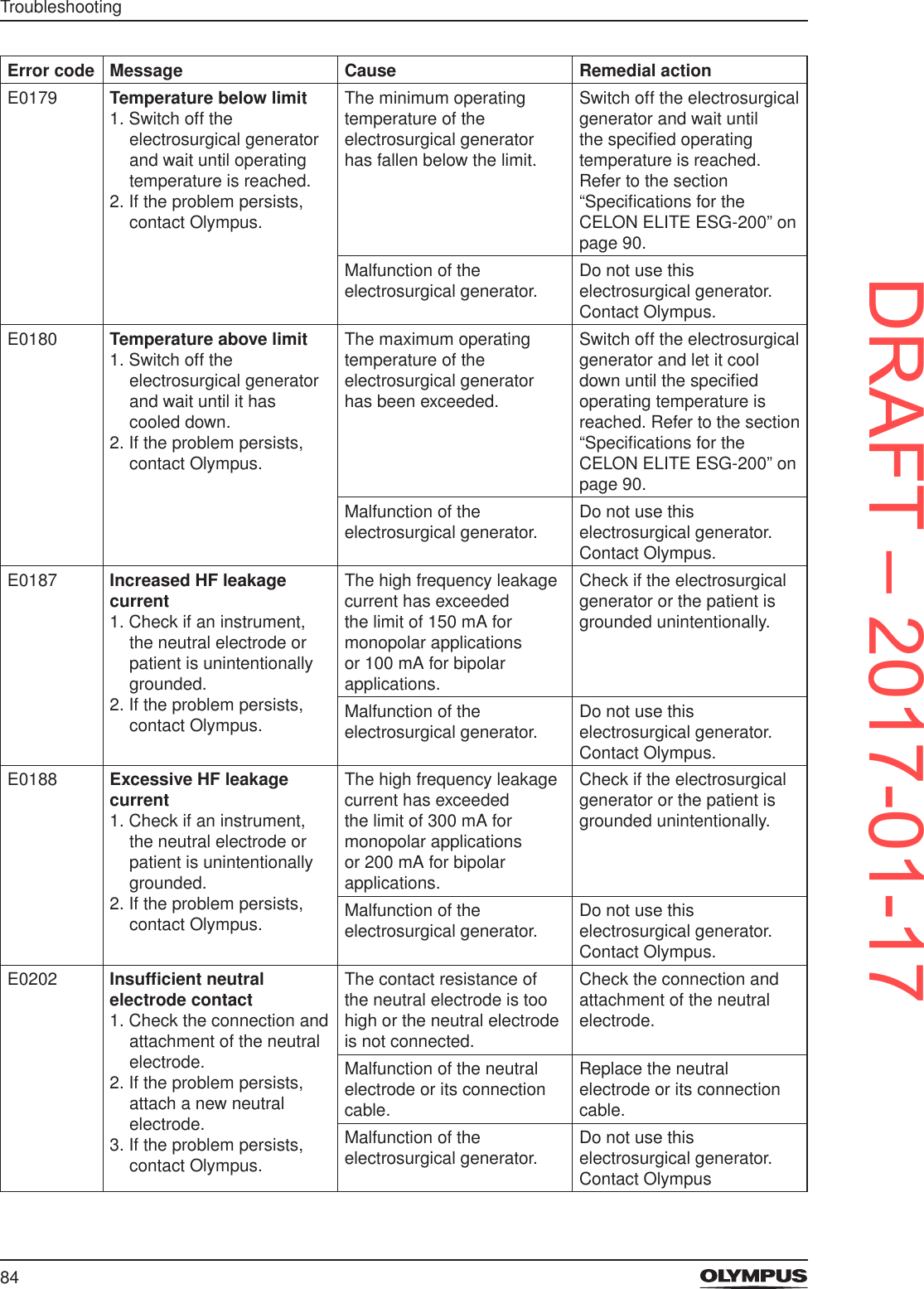
![85TroubleshootingError code Message Cause Remedial actionE0214 Low batteryIf the problem persists, contact Olympus.Malfunction of the electrosurgical generator.Do not use this electrosurgical generator. Contact Olympus.E0438 Procedure data error1. One or more procedures have been deleted. Press OK to continue.2. If the problem persists, contact Olympus.One or more saved procedures are deleted.Tap [OK] to close the error message and to continue.Malfunction of the electrosurgical generator.Do not use this electrosurgical generator. Contact Olympus.E0441 Device setting errorDevice settings have been set to default.If the problem persists, contact Olympus.All settings of the electrosurgical generator are set to default.The electrosurgical generator is ready for use after the error message is closed.Malfunction of the electrosurgical generator.Do not use this electrosurgical generator. Contact Olympus.E0660 No bipolar cuttingFor safety reasons the bipolar cutting modes cannot be activated while an RFITT mode is selected.A bipolar cutting mode as well as a bipolar RFITT mode are selected. Switch off the bipolar RFITT mode or select the mode SoftCoag.E0683 No compatible RFITT instrument connectedRFITT modes can only be activated if a compatible RFITT instrument is connected.There is no or an incompatible HF instrument connected.Connect an HF instrument that is compatible with this electrosurgical generator and its RFITT modes.E0687 Instrument wearout noteThe instrument is about to reach its maximum usage time.Replace the instrument if possible.The permitted usage span of the HF instrument is nearly reached. The error message is repeated after every new activation.Replace the HF instrument as soon as the treatment situation allows.E0688 Instrument wearout warningThe instrument has exceeded its maximum usage time.Replace the instrument to proceed.The permitted usage span of the HF instrument is exceeded. It is impossible to activate this HF instrument anymore.Replace the HF instrument.E0689 Refer to error code E0687.E0690 Refer to error code E0688.E0### ErrorElectrosurgical generator will automatically restart.If the problem persists, contact Olympus.Malfunction of the electrosurgical generator.The electrosurgical generator automatically restarts.If any error occurs permanently or repetitively, contact Olympus.Table: Troubleshooting – Overview of error messagesDRAFT – 2017-01-17](https://usermanual.wiki/Olympus-Winter-and-Ibe/ESG200.ESG200-UserMan-Celon-ELITE/User-Guide-3270684-Page-85.png)
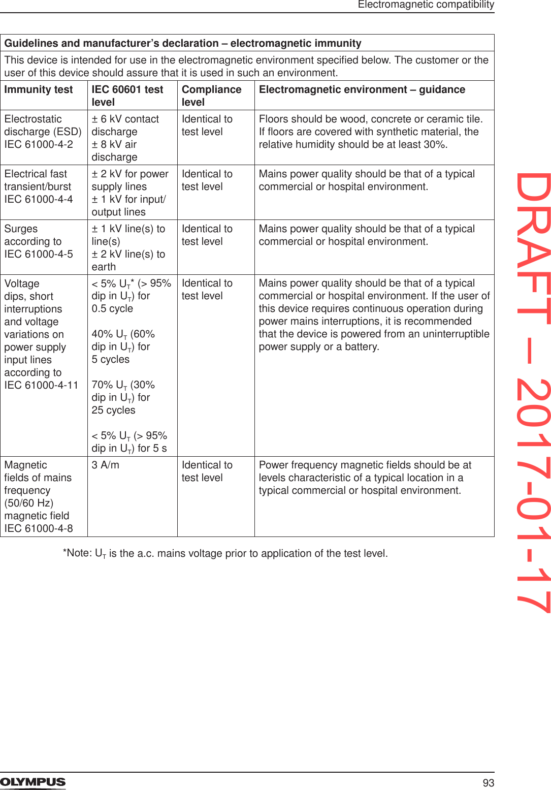
![94Electromagnetic compatibilityGuidance and manufacturer’s declaration – electromagnetic immunityThis device is intended for use in the electromagnetic environment specied below. The customer or user of this device should assure that it is used in such an environment.Immunity test IEC 60601 test levelCompliance levelElectromagnetic environment – guidanceConducted RF according to IEC 61000-4-63 Veff150 kHz to 80 MHz3 V Portable and mobile RF communications equipment should be used no closer to any part of the Olympus CELON ELITE ESG-200, including cables, than the recommended separation distance calculated from the equation applicable to the frequency of the transmitter.Recommended separation distanced = 1.2 √ Pd = 1.2 √ P 80 MHz to 800 MHzd = 2.3 √ P 800 MHz to 2.5 GHzwhere P is the maximum output power rating of the transmitter in watts [W] according to the transmitter manufacturer and d is the recommended separation distance in meters [m].Field strengths from xed RF transmitters, as determined by an electromagnetic site surveya, should be less than the compliance level in each frequency rangeb.Interference may occur in the vicinity of equipment marked with the following symbol:Radiated RF according to IEC 61000-4-33 V/m80 MHz to 2.5 GHz3 V/mNote 1: At 80 MHz and 800 MHz, the higher frequency range applies.Note 2: These guidelines may not apply in all situations. Electromagnetic propagation is affected by absorption and reection from structures, objects and people.a Field strengths from xed transmitters, such as base stations for radio (cellular/cordless) telephones and land mobile radios, amateur radio, AM and FM radio broadcast and TV broadcast cannot be predicted theoretically with accuracy. To assess the electromagnetic environment due to xed RF transmitters, an electromagnetic site survey should be considered. If the measured eld strength in the location in which the Olympus CELON ELITE ESG-200 is used exceeds the applicable RF compliance level above, the Olympus CELON ELITE ESG-200 should be observed to verify normal operation. If abnormal performance is observed, additional measures may be necessary, such as re-orienting or relocating the device.b Over the frequency range 150 kHz to 80 MHz, eld strengths should be less than 3 V/m.Recommended separation distances between portable and mobile RF communications equipment and this deviceThis device is intended for use in an electromagnetic environment in which radiated RF disturbances are controlled. The customer or user of this device can help prevent electromagnetic interference by maintaining a minimum distance between portable and mobile RF communications equipment (transmitters) and this device as recommended below, according to the maximum output power of the communications equipment.DRAFT – 2017-01-17](https://usermanual.wiki/Olympus-Winter-and-Ibe/ESG200.ESG200-UserMan-Celon-ELITE/User-Guide-3270684-Page-94.png)
![95Electromagnetic compatibilityRated output power of the transmitterP in WSeparation distance (d) according to frequency of the transmitter in meters (m)150 kHz to 80 MHzd = 1.2 √ P80 MHz to 800 MHzd = 1.2 √ P800 MHz to 2.5 GHzd = 2.3 √ P0.01 0.12 m 0.12 m 0.23 m0.1 0.38 m 0.38 m 0.73 m1 1.2 m 1.2 m 2.3 m10 3.8 m 3.8 m 7.3 m100 12 m 12 m 23 mFor transmitters rated at a maximum output power not listed above, the recommended separation distance [d] in metres [m] can be estimated using the equation applicable to the frequency of the transmitter, where P is the maximum output power rating of the transmitter in watts [W] according to the transmitter manufacturer.Note 1: For 80 MHz and 800 MHz, the separation distance for the higher frequency range applies.Note 2: These guidelines may not apply in all situations. Electromagnetic propagation is affected by absorption and reection from structures, objects and people.DRAFT – 2017-01-17](https://usermanual.wiki/Olympus-Winter-and-Ibe/ESG200.ESG200-UserMan-Celon-ELITE/User-Guide-3270684-Page-95.png)


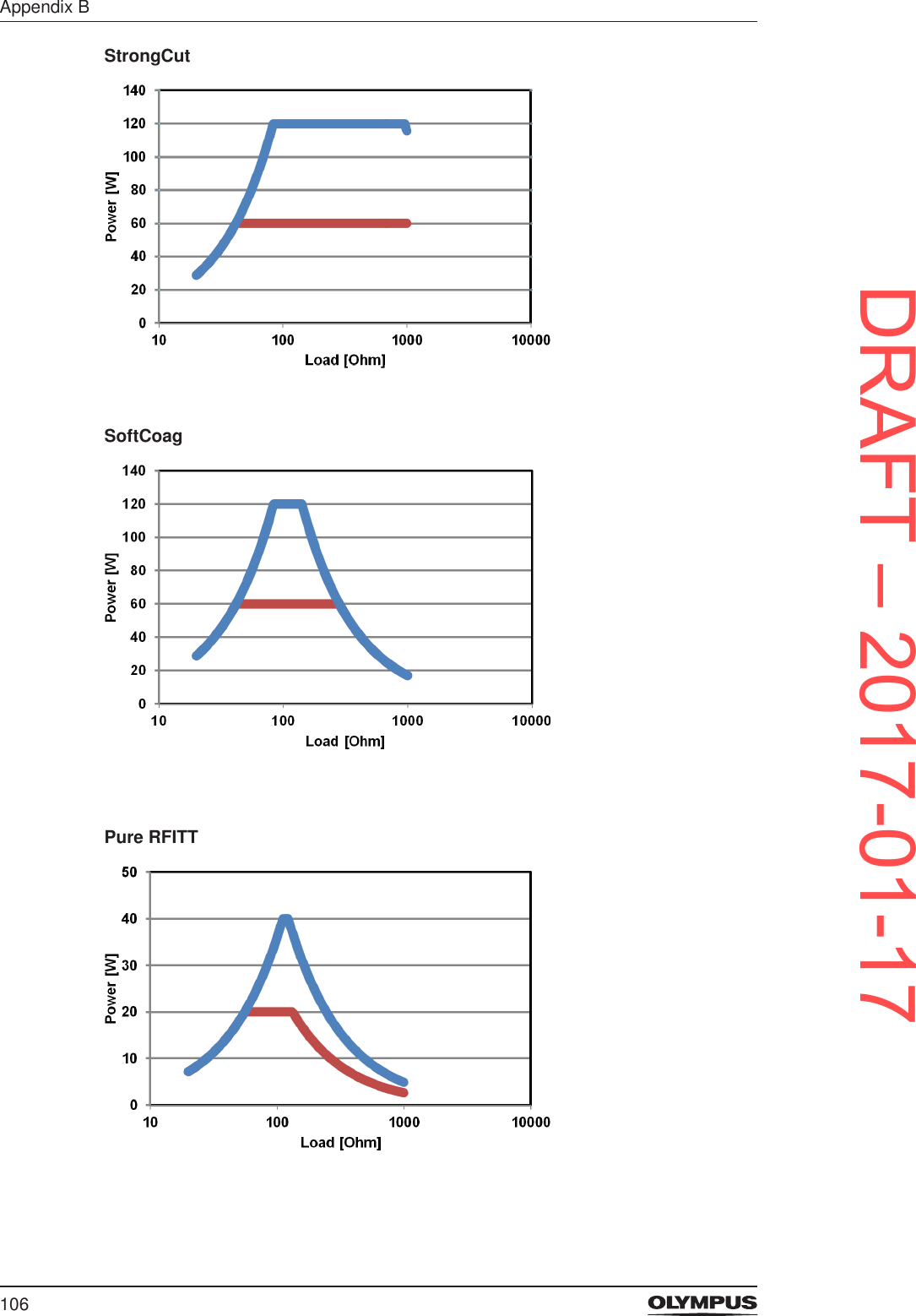
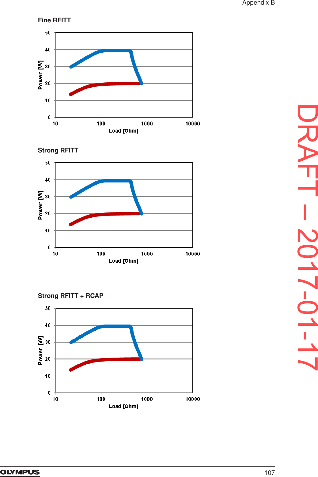
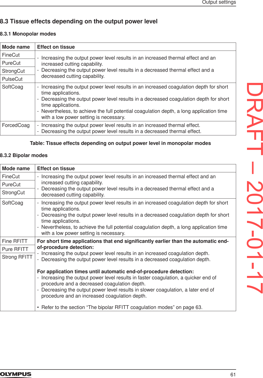
![104Appendix BStrongCutPulseCutSoftCoag02040608010012014010 100100010000Power [W]Load [Ohm]DRAFT – 2017-01-17](https://usermanual.wiki/Olympus-Winter-and-Ibe/ESG200.ESG200-UserMan-Celon-ELITE/User-Guide-3270684-Page-104.png)
![105Appendix BForcedCoagOutput characteristics of bipolar modesFineCutPureCut02040608010012014010 100100010000Power [W]Load [Ohm]DRAFT – 2017-01-17](https://usermanual.wiki/Olympus-Winter-and-Ibe/ESG200.ESG200-UserMan-Celon-ELITE/User-Guide-3270684-Page-105.png)