Olympus Winter and Ibe ESG200 Electrosurgical Generator CELON Elite ESG-200 (WA90001A, WA90002A) & CELON Precision (WA90008A, WA90009A) User Manual W7093251 01 indb
Olympus Winter & Ibe GmbH Electrosurgical Generator CELON Elite ESG-200 (WA90001A, WA90002A) & CELON Precision (WA90008A, WA90009A) W7093251 01 indb
Contents
- 1. ESG200 UserMan CelonPrecision
- 2. ESG200 UserMan Celon ELITE
ESG200 UserMan Celon ELITE
Caution: Federal (USA) law restricts this device to sale by or on the order of a physician.
INSTRUCTIONS FOR USE
ELECTROSURGICAL GENERATOR
CELON ELITE
ESG-200
WA90001A
WA90002A
DRAFT – 2017-01-17
DRAFT – 2017-01-17
Contents
1 General information ...........................................................................................................9
1.1 User instructions ...............................................................................................................9
1.2 Signal words ......................................................................................................................9
1.3 Conventions throughout this document .............................................................................9
1.4 List of abbreviations ........................................................................................................10
1.5 Manufacturer ...................................................................................................................10
2 Safety information ............................................................................................................11
2.1 Intended use ...................................................................................................................11
2.2 Contraindications ............................................................................................................11
2.3 High frequency surgery ................................................................................................... 11
2.4 User qualication ............................................................................................................11
2.5 Environment of use .........................................................................................................12
2.6 General dangers, warnings and cautions........................................................................12
2.6.1 User-related error prevention .................................................................................12
2.6.2 Risks regarding environmental conditions .............................................................13
2.6.3 Risks regarding accessories ..................................................................................14
2.6.4 Risks regarding electric shock ...............................................................................14
2.6.5 Risks regarding burns ............................................................................................15
2.6.6 Potential hazards to the heart ................................................................................16
2.6.7 Risks regarding re and explosion .........................................................................17
2.6.8 Procedural hazards and complications ..................................................................18
3 Product description and functional principles ..............................................................20
3.1 Scope of delivery ............................................................................................................20
3.2 Symbols ..........................................................................................................................20
3.3 Nomenclature and functional principles of the software features ....................................21
3.3.1 CQM – Contact Quality Monitoring for the neutral electrode .................................22
3.3.2 HPCS – High Power Cut Support ..........................................................................22
3.3.3 Autostart for the bipolar mode SoftCoag ................................................................22
3.3.4 FSM – Fast Spark Monitor .....................................................................................22
3.4 Features for selected CELON bipolar applicators ...........................................................22
3.4.1 RFITT – Radiofrequency induced thermotherapy .................................................. 23
3.4.2 RCAP – Resistance Controlled Automatic Power for RFITT .................................. 23
3.4.3 Automatic instrument recognition ...........................................................................23
3.4.4 Automatic wear-out detection ................................................................................. 23
3.5 Nomenclature and functional principles of the hardware ................................................25
3.5.1 The front panel ....................................................................................................... 25
3.5.2 The rear panel ........................................................................................................26
3.5.3 The double pedal foot switch .................................................................................27
3.5.4 The connecting cable for the neutral electrode ...................................................... 27
3.6 Nomenclature and functional principles of the touch screen ...........................................28
3.6.1 The All Screen .......................................................................................................28
3.6.2 The Set Screen ......................................................................................................30
3.6.3 The Mode Screen ..................................................................................................31
3.6.4 The screens for system settings ............................................................................31
3.6.5 Icons displayed on the touch screen ......................................................................33
3.7 Warranty ..........................................................................................................................34
4 Installation ........................................................................................................................35
4.1 General inspection ..........................................................................................................35
4.2 Placement of the electrosurgical generator .....................................................................35
DRAFT – 2017-01-17
4.3 Connecting the electrosurgical generator to the mains electricity ................................... 35
4.3.1 Before connecting ..................................................................................................36
4.3.2 Connecting ............................................................................................................. 36
4.4 Connecting the double pedal foot switch ........................................................................37
4.4.1 Before connecting ..................................................................................................37
4.4.2 Connecting ............................................................................................................. 37
5 System settings ................................................................................................................39
5.1 Operation of the touch screen ......................................................................................... 39
5.2 Overview of system settings ...........................................................................................39
5.3 Select Procedure settings ...............................................................................................40
5.4 Foot switch assignment and Autostart ............................................................................41
5.5 Select Menu settings ....................................................................................................... 42
5.5.1 Save Procedure - Saving and overwriting procedure settings ...............................42
5.5.2 Delete Procedure ...................................................................................................44
5.5.3 Languages .............................................................................................................44
5.5.4 Touch Tone ............................................................................................................45
5.5.5 Autostart Setup ......................................................................................................45
5.5.6 Software Version ....................................................................................................45
5.5.7 Safety Test .............................................................................................................46
5.5.8 Bipolar Cut Setup ................................................................................................... 46
5.5.9 Service ................................................................................................................... 46
5.5.10 Volume control .....................................................................................................47
5.5.11 Brightness control ................................................................................................47
6 Connecting HF instruments ............................................................................................49
6.1 Safety information for connecting HF instruments ..........................................................49
6.2 Description of the output sockets ....................................................................................50
6.3 Connecting ......................................................................................................................51
7 Neutral electrode operation ............................................................................................53
7.1 Safety information for neutral electrode operation ..........................................................53
7.2 Split type and non-split type neutral electrodes and CQM ..............................................54
7.3 Meaning of CQM indicator condition ...............................................................................55
7.4 Correct usage of neutral electrodes ................................................................................55
7.5 Connecting to the electrosurgical generator ...................................................................56
7.5.1 Connecting a neutral electrode with a pre-attached cable ..................................... 56
7.5.2 Connecting a neutral electrode without a pre-attached cable ................................ 57
7.6 Verifying the contact quality monitor indicator ................................................................. 58
8 Output settings................................................................................................................59
8.1 Safety information on output settings .............................................................................. 59
8.2 Overview of output modes ..............................................................................................59
8.2.1 Monopolar modes ..................................................................................................59
8.2.2 Bipolar modes ........................................................................................................60
8.3 Tissue effects depending on the output power level .......................................................61
8.3.1 Monopolar modes ..................................................................................................61
8.3.2 Bipolar modes ........................................................................................................61
8.4 Selecting the appropriate output settings ........................................................................ 62
8.5 The bipolar RFITT coagulation modes ............................................................................63
8.6 Output settings for selected CELON bipolar applicators .................................................65
9 Inspection before operation ............................................................................................67
9.1 Inspecting the supply of power ........................................................................................67
9.2 Inspecting the touch screen ............................................................................................67
9.3 Inspecting the foot switch assignment ............................................................................68
DRAFT – 2017-01-17
9.4 Inspecting the alarm system ...........................................................................................69
10 Operation ........................................................................................................................70
10.1 Safety information for operation ....................................................................................70
10.2 Activating .......................................................................................................................71
10.2.1 Prior to activating .................................................................................................71
10.2.2 Limited activation time .........................................................................................71
10.2.3 Functional principles of activation ........................................................................72
10.3 After use ........................................................................................................................74
10.3.1 Disconnecting ......................................................................................................75
11 Reprocessing .................................................................................................................76
11.1 General information for reprocessing ............................................................................76
11.2 Cleaning ........................................................................................................................76
11.3 Disinfection ....................................................................................................................77
11.4 Other HF equipment......................................................................................................77
12 Troubleshooting .............................................................................................................78
12.1 General problems ..........................................................................................................78
12.2 Error messages ............................................................................................................. 80
12.2.1 Overview of error messages ................................................................................82
13 Maintenance, repair and shipment ............................................................................... 86
13.1 Annual safety check ......................................................................................................86
13.2 Repair ............................................................................................................................86
13.3 Shipment ....................................................................................................................... 86
14 Storage and disposal .....................................................................................................87
14.1 Storage ..........................................................................................................................87
14.2 Disposal ........................................................................................................................87
15 Compatible equipment ..................................................................................................88
15.1 System chart .................................................................................................................88
15.2 Compatible neutral electrodes ......................................................................................89
16 Specications .................................................................................................................90
16.1 Specications for the CELON ELITE ESG-200 .............................................................90
16.2 Specications for the double pedal foot switch (WB50402W) .......................................91
16.3 Specications for the cord set .......................................................................................91
17 Electromagnetic compatibility ......................................................................................92
Appendix A ..........................................................................................................................97
Alarm system ........................................................................................................................97
Output tone information .........................................................................................................98
Touch tone and start melody ................................................................................................. 99
Appendix B ........................................................................................................................101
Mode characteristics according to IEC 60601-2-2 ..............................................................101
Characteristics of High Power Cut Support (HPCS) ...........................................................102
Output characteristics .........................................................................................................103
DRAFT – 2017-01-17
Figures
Figure 3.1 Front panel of the CELON ELITE ESG-200..................................................25
Figure 3.2 Rear panel ....................................................................................................26
Figure 3.3 Double pedal foot switch ..............................................................................27
Figure 3.4 Cable for neutral electrode, MAJ-814 ...........................................................27
Figure 3.5 BIPOLAR pane ............................................................................................. 28
Figure 3.6 MONOPOLAR pane .....................................................................................28
Figure 3.7 Buttons for system settings ...........................................................................29
Figure 3.8 Buttons and symbols on the All Screen ........................................................ 29
Figure 3.9 Set Screen ....................................................................................................30
Figure 3.10 Mode Screen for monopolar cutting .............................................................31
Figure 3.11 Hierarchy list of the 3 right-hand sided buttons on the All Screen ................32
Figure 4.1 Connecting the cord set to the electrosurgical generator .............................36
Figure 4.2 Connecting the foot switch to the electrosurgical generator .........................38
Figure 5.1 Buttons for system settings ...........................................................................39
Figure 5.2 Screen [Select Procedure] ............................................................................40
Figure 5.3 Screen [Assign Foot Switch] ......................................................................... 41
Figure 5.4 Screen [Select Menu] ...................................................................................42
Figure 5.5 Onscreen keyboard (letters and numbers) ...................................................43
Figure 5.6 Onscreen keyboard (upper/lower key and backspace key) ..........................43
Figure 5.7 Volume control .............................................................................................. 47
Figure 5.8 Brightness control ......................................................................................... 48
Figure 6.1 CAUTION - Correct connection of a monopolar 1-pin plug with a 4 mm pin
diameter ........................................................................................................49
Figure 6.2 CAUTION - Do not connect a 2-pin plug with 4 mm pin diameters to the MO-
NOPOLAR socket .........................................................................................50
Figure 6.3 MONOPOLAR output socket specications for WA90001A .........................51
Figure 6.4 MONOPOLAR output socket specications for WA90002A .........................51
Figure 6.5 Bipolar output socket specications..............................................................51
Figure 7.1 Error message E0202 “Insufcient neutral electrode contact” ......................54
Figure 7.2 Message box “Neutral electrode” ..................................................................54
Figure 7.3 Connecting the plug of the neutral electrode ................................................57
Figure 7.4 Fixing the neural electrode to the connecting cable .....................................57
Figure 7.5 Split type indicator for CQM shining red on the Set Screen and on the All
Screen ..........................................................................................................58
Figure 8.6 All Screen .....................................................................................................62
Figure 8.7 Set Screen for monopolar modes .................................................................63
Figure 8.8 Mode Screen for monopolar cutting modes .................................................. 63
Figure 8.1 Counters on the Set Screen and during activation .......................................64
Figure 8.2 Error message E0660 “No bipolar cutting” ...................................................65
Figure 8.3 Automatic instrument recognition .................................................................65
Figure 8.4 Incompatible settings .................................................................................... 66
Figure 9.1 Changing from the All Screen to the Set Screen ..........................................67
Figure 9.2 Changing from the All Screen to the screen [Select Menu] ..........................68
Figure 9.3 Changing from the All Screen to the screen [Assign Foot Switch] ...............68
Figure 9.4 Error message E0202 “Insufcient neutral electrode contact” ......................69
Figure 10.1 Error message E0115: "Activation time limit exceeded" ...............................72
Figure 10.2 Background color for active coagulation on the All Screen ..........................73
Figure 10.3 Background color for active coagulation on the Set Screen .........................73
Figure 10.4 Error message E0141 "Power set to zero (--)" ..............................................74
Figure 12.1 Error message E0002 “Short circuit” ............................................................81
Figure 15.1 System chart for CELON ELITE ESG-200 ...................................................88
Characteristics of HPCS ..................................................................................................102
DRAFT – 2017-01-17
DRAFT – 2017-01-17
DRAFT – 2017-01-17
9
General information
1 General information
1.1 User instructions
• Before use, thoroughly read these instructions for use, and the instructions for use of all
other products that will be used during the procedure.
• If the required instructions for use are missing, immediately contact an Olympus
representative.
• Keep the instructions for use in a safe, accessible location.
1.2 Signal words
The following signal words are used throughout this document.
DANGER
Indicates a hazardous situation which, if not avoided, will result in death or serious injury.
WARNING
Indicates a potentially hazardous situation which, if not avoided, could result in death or
serious injury.
CAUTION
Indicates a potentially hazardous situation which, if not avoided, may result in minor or
moderate injury. It may also be used to alert against unsafe practices or potential equipment
damage.
NOTICE
Indicates a property damage message.
1.3 Conventions throughout this document
This is the safety alert symbol. It is used to alert the user to potential physical injury hazards.
Observe all safety messages that follow this symbol to avoid possible injury.
This symbol indicates additional helpful information.
1. A numeration indicates a sequence of actions.
2. ...
• Bullet points indicate individual actions or different options for action.
- Dashes indicate the listing of data, options or objects.
1) Numbers with right parenthesis name elements in illustrations.
[example]
Bracketed terms refer to elements in the graphical user interface. Such elements can be:
- icons
- buttons
- menu items
- dialog elements
DRAFT – 2017-01-17

10
General information
1.4 List of abbreviations
AC Alternating current
CQM Contact Quality Monitor
DC Direct current
EMC Electromagnetic compatibility
ESD Electrostatic discharge
ESG Electrosurgical generator
FSM Fast Spark Monitor
GSM Global system for mobile communication
HF High frequency
HPCS High Power Cut Support
ICD Implanted cardioverter debrillator
IED Implanted electronic device
RFID radio-frequency identication
RFITT Radiofrequency induced thermotherapy
RCAP Resistance Controlled Automatic Power
UDI Unique device identier
1.5 Manufacturer
Olympus Winter & Ibe GmbH
Kuehnstr. 61
22045 Hamburg
Germany
DRAFT – 2017-01-17

11
Safety information
2 Safety information
2.1 Intended use
Electrosurgical generator intended for tissue cutting and coagulation in conjunction with
electrosurgical accessories and ancillary equipment.
2.2 Contraindications
Electrosurgical interventions are contraindicated if, in the judgment of the physician,
tissue coagulation and cutting could have a negative effect on the state of the patient.
Electrosurgical interventions may be contraindicated for patients with implanted electronic
devices (e.g. pacemakers or cardioverter-debrillators), a weakened immune system or
blood coagulation disorders.
2.3 High frequency surgery
If there is an ofcial standard on the applicability of high frequency treatment as dened by
a national or local medical administration or other institutions, such as an academic society,
follow that standard when performing the procedure.
Before performing any high frequency treatment, thoroughly study the properties, purposes,
and effects as well as the nature, extent, probability and imminence of possible risks
associated with the planned treatment. Furthermore, study any alternative therapeutic
method that can be performed.
Carry out high frequency treatment only when its benets outweigh its risks. Fully explain
to the patient the possible benets and risks of high frequency treatment as well as those
of any therapeutic method that can be performed instead of electrosurgery. Perform high
frequency treatment only after patient consent is granted.
During high frequency treatment, continue to evaluate the potential benets and risks. Stop
the treatment if the risks become greater than the possible benets to the patient.
2.4 User qualication
Medical use
If the required qualication for medical personnel who uses electrosurgical generators
is dened by a national or local medical administration or other institutions, such as an
academic society, then follow that standard.
If there is no such standard:
- The user must be a physician or medical personnel under supervision of a physician.
- The user must have experience with electrosurgical procedures that are used for the
therapy.
- The user must have received appropriate training in using this electrosurgical generator.
This training is provided during installation and commissioning of the CELON ELITE
ESG-200 by trained qualied personnel that has been authorized by Olympus.
These instructions for use do not explain or discuss clinical procedures.
DRAFT – 2017-01-17

12
Safety information
Commissioning
The electrosurgical generator must be properly installed and commissioned by trained
qualied personnel that has been authorized by Olympus.
Annual safety check
The annual safety check may only be carried out by a qualied electrician with sufcient
experience in maintaining medical electrical devices.
Repair
Repair of the product may only be performed by authorized service centers. Otherwise,
Olympus cannot be held responsible for the safety and performance of the product.
2.5 Environment of use
Medical use
This product is intended to be used in operating rooms or physicians’ ofces.
Annual safety check
Appropriate equipment for performing the safety check must be available. Refer to the
section “Annual safety check” on page 86.
2.6 General dangers, warnings and cautions
High frequency leakage current or spark discharge may cause burns to the user and the
patient. Always prepare for an emergency operation if unintentional burns, bleeding and
perforation occur.
The following dangers, warnings and cautions apply to the general handling of the product.
This information is to be supplemented by the dangers, warnings and cautions given in each
chapter in this document or in the instructions for use of any product being used with this
product.
2.6.1 User-related error prevention
WARNING
Improper use
Safety and effectiveness of electrosurgery do not only depend on the design of the used
equipment. To a major extent, the success of electrosurgical interventions depends on
factors that are under the control of the user. Therefore, it is particularly important to read,
understand and follow the instructions that are supplied with the electrosurgical generator
and with the accessories. Improper use can cause severe procedural complications and
equipment damage and could result in injuries to the patient, the user and the medical
personnel.
Only use the electrosurgical generator as outlined in these instructions for use.
• Before each use, inspect the electrosurgical generator and all accessories according to
the corresponding instructions for use.
CAUTION
Annual safety checks
To maintain device performance and electrical safety, annual safety checks must be carried
out on the electrosurgical generator and the foot switch. Otherwise, malfunction of the
devices could occur which may result in injury to the patient.
DRAFT – 2017-01-17
13
Safety information
• Make sure that the annual safety check is carried out regularly.
• Refer to the information in the section "Annual safety check" on page 86.
• Observe national statutory regulations.
2.6.2 Risks regarding environmental conditions
DANGER
Explosive atmosphere
The electrosurgical generator is not explosion proof. Using the electrosurgical generator in
explosive atmosphere will result in serious injury to the patient, the user and the medical
personnel.
• Do not use the electrosurgical generator within an explosive atmosphere.
CAUTION
The electrosurgical generator can disturb other equipment
The electrosurgical generator complies with the standards as described in the chapter
"Electromagnetic compatibility" on page 92. However, during activation, high frequency
signals or spark discharge noise generated by the electrosurgical generator can disturb
neighboring electrical equipment. Malfunction of the devices could occur, e.g. the monitor of
endoscopic imaging equipment might freeze or black out, which may result in injury to the
patient.
• Follow the instructions regarding electromagnetic ambient conditions given in the chapter
"Electromagnetic compatibility" on page 92.
• Make sure that electrosurgical generator is not used adjacent to or stacked with equipment
that is not part of this electrosurgical generator or system.
• Before use, thoroughly conrm the compatibility of all equipment.
• Do not use the electrosurgical generator in conjunction with:
- Electrical equipment for which the safety against leakage current is not conrmed.
- Electrosurgical equipment for which the safety in combined use is not conrmed.
• Do not loop cables.
• Do not bundle cables together with cables belonging to other medical equipment.
CAUTION
Strong electromagnetic radiation can disturb the electrosurgical generator
Equipment that produces strong electromagnetic radiation can cause malfunction of the
electrosurgical generator which may result in injury to the patient. Equipment that produces
strong electromagnetic radiation is, e.g. microwave medical treatment equipment, short-
wave medical treatment equipment, magnetic resonance imaging equipment, radio or
mobile phones.
• Do not use the electrosurgical generator in a location exposed to strong electromagnetic
radiation.
CAUTION
Unsuitable operating conditions
Using the electrosurgical generator under conditions other than specied can compromise
the performance and can damage the equipment which may result in patient injury.
• Only use the electrosurgical generator according the operating conditions as described in
the chapter "Specications" on page 90.
DRAFT – 2017-01-17
14
Safety information
2.6.3 Risks regarding accessories
WARNING
Mechanical stress
Excessive mechanical stress applied to the cords can damage the cords and its insulations.
This can result in electric shock and thermal injury to the patient, the user and the medical
personnel. Furthermore, mechanical stress to the cords can cause malfunction of the
electrosurgical equipment which can result in patient injury.
• Do not excessively bend, strain or squeeze the cords.
WARNING
Damaged equipment and accessories
The use of damaged equipment or of equipment with improper functioning may cause
electric shock, mechanical injury, infection and thermal injury to the patient and the user.
• Before each use, observe the instructions in the section "Inspection before operation" on
page 67.
• Do not use damaged equipment or equipment with improper functioning.
• Replace damaged equipment or equipment with improper functioning.
WARNING
Risk of sparkover
There is a risk of sparkover leading to electrical injury, thermal injury and/or unintended
nerve stimulation.
• Check the maximum rated voltage of the other HF equipment.
• Make sure that the maximum output voltage of the electrosurgical generator does not
exceed the lowest maximum rated voltage of any of the HF equipment used during the
procedure.
CAUTION
Incompatible equipment
Using incompatible equipment may lead to injury of the patient and/or the user as well as
damage to the product.
• For information on compatible equipment, refer to the chapter "Compatible equipment" on
page 88.
2.6.4 Risks regarding electric shock
WARNING
Grounding failure
There is a risk of electric shock if the housing of the electrosurgical generator is not
grounded.
• Only connect the cord set to a properly grounded xed socket-outlet.
• Do not use an adapter for an incompatible grounded xed socket-outlet as it can impair
safe operation of the electrosurgical generator.
WARNING
Liquids
If liquids get on or into the electrosurgical generator, then this could cause electric shock to
the user as well as damage to the electrosurgical generator which could result in injury to
the user.
• Keep liquids away from all electrical equipment.
• If liquids get on or into the electrosurgical generator, then immediately stop the operation.
DRAFT – 2017-01-17

15
Safety information
CAUTION
Opening the housing
There is a risk of electric shock when opening the housing of the electrosurgical generator.
• Do not open the housing of the electrosurgical generator.
• Repair and service of the electrosurgical generator may only be performed by trained
qualied servicing personnel that has been authorized by Olympus.
2.6.5 Risks regarding burns
WARNING
Power settings
The selected output power should be as low as possible for the intended purpose. If the
output power initially is set to a level that is too high, then the electrode's insulation can be
damaged. This could result in burns to the patient and the user.
However, the PulseCut mode and all RFITT modes present an unacceptable risk when
used with power settings that are too low. The risk of excessive thermal effects rises if the
output power setting is too low when using these modes.
• For appropriate power settings refer to the tables with the modes characteristics in the
“Appendix A” on page 97.
• Prior to the procedure, perform basic testing with the electrosurgical generator.
WARNING
Unintended tissue contact
When the output of the electrosurgical generator is active, then unintended contact between
tissue and the active part of the HF instrument can cause burns to the patient, the user and
the medical personnel.
• Store temporarily unused HF instruments in an electrically insulated container.
• Do not place unused HF instruments on the patient.
WARNING
Unintended current ow
Unintended current ow may cause injury to the patient and the user. The patient must be
insulated against all electrically conductive parts.
• Make sure that the patient does not come in contact with any metal parts.
• Ground the operating table.
• Place the patient on a dry, electrically insulating surface.
• Make sure that the patient’s clothes are dry.
• Prevent any contact between different skin surfaces (arms, legs) of the patient. Place dry
gauze between the body and arms and between the legs to prevent such contact.
• Prevent any skin contact between the patient and the user.
• Remove any metallic items from the patient, e.g. wristwatches, jewelry.
WARNING
Using two electrosurgical generators
Using the electrosurgical generator in conjunction with another electrosurgical generator
could result in patient and user injury due to the concentration of electric current.
• Keep HF instruments that are connected to the unused electrosurgical generator away
from the target area while the other generator is in operation.
• Do not activate output of both generators simultaneously.
DRAFT – 2017-01-17
16
Safety information
WARNING
Using physiological monitoring equipment
Current may ow to the monitoring electrodes and can cause thermal injury where the
monitoring electrodes are attached. Especially, the use of needle electrodes can result in
burns to the patient.
• Place the physiological monitoring electrodes as far away as possible from the electrodes
of the HF instrument.
• Do not use needle monitoring electrodes.
• Use physiological monitoring equipment with HF current limiting measures.
WARNING
Surgical gloves
During operation, HF current, especially leakage current, could ow via the user and the
assistant. This could result in burns to the user and the assistant.
• The user and the assistant must wear surgical gloves.
CAUTION
Unintended current ow and HF leakage current
Unintended current ow and HF leakage current may cause thermal injury to the patient.
The patient must be insulated against all electrically conductive parts.
• Ground the operating table.
• Make sure that the patient does not come in contact with metal parts, e.g. the operating
table.
• Place the patient on a dry, electrically insulating surface.
• Make sure that the patient’s clothes are dry.
• Prevent any contact between different skin surfaces (arms, legs) of the patient. Place dry
gauze between the body and arms and between the legs to prevent such contact.
• Prevent any skin contact between the patient and the user.
• Remove any metallic items from the patient, e.g. wristwatches, jewelry.
• Route all connecting cables so that they are not in direct contact with the patient.
• Route all connecting cables so that they are not in contact with other cables.
2.6.6 Potential hazards to the heart
DANGER
Malfunction of pacemakers and debrillators
Using HF equipment on patients with implanted electronic devices, e.g. cardiac pacemakers
or cardioverter debrillators, can cause failure of the implanted electronic device. Failure of
the implanted electronic device will affect the heart and could result in cardiac arrest.
• Prior to the HF procedure, conrm its safety with a cardiologist or the manufacturer of the
implanted electronic device.
• For monopolar procedures, position the neutral electrode so that the current pathway does
not pass through or near the implanted electronic device and its lead system.
• Do not apply the HF instrument in close proximity to the implanted electronic device.
WARNING
Electric shock hazard
When using the electrosurgical generator for procedures in the vicinity of the heart, note that
spark discharge can affect the heart and could result in cardiac arrest.
• Make sure to use the lowest necessary output power for procedures in the vicinity of the
heart.
DRAFT – 2017-01-17

17
Safety information
WARNING
Cardiac emergency
• Keep ready a debrillator.
• Before operating the debrillator, remove all electrosurgical equipment from the patient.
2.6.7 Risks regarding re and explosion
The surgical application of electrical energy can ignite ammable gases, substances and
materials.
DANGER
Ignitable anaesthetics and gases
The igniting of ammable gases, especially anaesthetics, will cause serious injuries to the
patient, the user and the medical personnel.
• Take precautionary measures to keep away ammable gases from the site of intervention.
• Do not use ammable anaesthetics, e.g. nitrous oxygen or oxygen.
WARNING
Ignitable agents for cleaning and disinfection and other substances
The igniting of ammable substances, e.g. agents for cleaning and disinfection, can cause
serious injuries to the patient, the user and the medical personnel.
• If possible, only use non-ammable agents for cleaning and disinfection.
• Before the electrosurgical generator is used, allow ammable substances to evaporate.
• Make sure that there are no ammable solutions on the patient’s skin, e.g. under the
neutral electrode.
• Make sure that there are no ammable solutions in the body cavity of the patient.
WARNING
Ignitable materials
Sparks that occur during normal operation of the HF equipment can ignite ammable
materials, e.g. absorbent cotton or gauze and also body hair. This could result in serious
injuries to the patient, the user and the medical personnel.
• Use soluble surgical lubricating jelly to cover hair close to the site of intervention.
• Do not apply materials like cotton or gauze simultaneously with the HF instrument to the
site of intervention.
WARNING
Ignitable gas in the gastrointestinal tract
Flammable gases within the intestines of the patient could cause re or explosion when
applying HF current. This could result in serious injury to the patient.
• Prior to the HF procedure, replace intestine gases by air or by other non-ammable gases.
WARNING
Fuses
Using inadequate fuses can cause electrical re within the electrosurgical generator. This
could result in injury to the patient, the user and the medical personnel.
• Fuses must only be replaced by a qualied electrician with sufcient experience in
maintaining medical electrical devices.
• Only use fuses as specied in the section “Specications for the CELON ELITE ESG-200”
on page 90.
• Before changing the fuses, disconnect the electrosurgical generator from the mains
electricity.
DRAFT – 2017-01-17
18
Safety information
2.6.8 Procedural hazards and complications
DANGER
Procedural hazards and complications
Insufcient knowledge of the user about the medical literature and about the specic
procedural hazards will result in severe complications that can result in death of the patient.
• The electrosurgical generator must only be used by physicians who have experience with
the electrosurgical procedure that is used for the specic therapy.
• To respond to possible complications during the procedure consider the following:
• Prepare at least one hemostatic procedure: coagulation, clipping or local injection.
• Make sure that emergency equipment for life-saving, intubation and appropriate
pharmaceuticals are located in or near the procedure room.
• Prepare a spare electrosurgical generator or an alternative procedure to avoid
interruption of treatment due to an unexpected electrosurgical generator failure during
the treatment.
• If any abnormal output is suspected during the operation, immediately terminate the
use of the equipment.
• If the foot switch does not react, switch off the electrosurgical generator. Malfunction
of the equipment can cause an unintended increase of output energy.
• Use physiological monitoring equipment throughout the entire procedure.
• Consider the use of a bipolar mode for procedures where the HF current could ow
through parts of the body with a relatively small cross sectional area.
• It is not recommended to use electrosurgery for circumcisions because of the risk of
thermal injuries. The risk can be reduced if metal parts of any kind (e.g. clamps) or
monopolar HF instruments are avoided.
WARNING
Electrosurgical smoke
Electrosurgical interventions produce smoke. When unltered smoke is inhaled, then this
can affect the health of the user and the medical personnel.
• Wear surgical masks during the procedure.
• Make sure that adequate ventilation, surgical smoke evacuators or other means is
provided in the operating room.
WARNING
Output performance
Tissue coagulum that builds up at the HF instrument can impede the output performance
of the electrosurgical generator. Increasing the output level can damage the electrosurgical
generator and can result in injury to the patient.
• Carefully clean eschar affected areas of the HF instrument. Refer to the instructions for
use of the HF instrument.
• If necessary, replace the HF instrument.
If non-insulated grasping forceps are used during endoscopic interventions, then the HF
current is dispersed via the endoscope which impedes the output performance and which
can result in injury to the patient.
• Only use isolated grasping forceps during endoscopic interventions.
DRAFT – 2017-01-17

19
Safety information
WARNING
Electrical stimulation of nerves and muscles
Low frequency electrical currents or intense high frequency electrical currents can stimulate
nerves and muscles which may result in violent spasms or muscle contractions of the
patient. Low frequency electrical currents may be generated by a partial rectication of
intense high frequency electrical current, in particular when there is a spark discharge to the
tissue or to another metallic object. Intense high frequency electrical currents can occur at
the beginning of an electrosurgical cut or when using high output power settings.
• Use the lowest appropriate output power level. Be aware that certain modes present an
unacceptable risk with power settings that are too low. With the PulseCut mode and all
RFITT modes the risk of excessive thermal effects rises if the output power setting is too
low.
• For appropriate power settings refer to the tables with the modes characteristics in the
“Appendix B” on page 101.
CAUTION
Generator defect
Short circuits can cause malfunction or damage of the electrosurgical generator which may
cause an undesirably high output of power. This could result in injury to the patient.
• Make sure that the electrodes of an HF instrument do not come in contact with each other.
• Do not touch metallic parts with the HF instrument.
DRAFT – 2017-01-17
20
Product description and functional principles
3 Product description and functional principles
3.1 Scope of delivery
• Before use, check that all items listed below are available.
• Contact an Olympus representative or an authorized service center if any items are
missing or damaged.
WA90001A or WA90002A
- Electrosurgical generator CELON ELITE ESG-200
- Foot switch including connecting cable (WB50402W)
- Instructions for use
A cord set for connecting the electrosurgical generator to the mains electricity is not included
as the plug types depend on national standards. Refer to the section “Specications for the
cord set” on page 91.
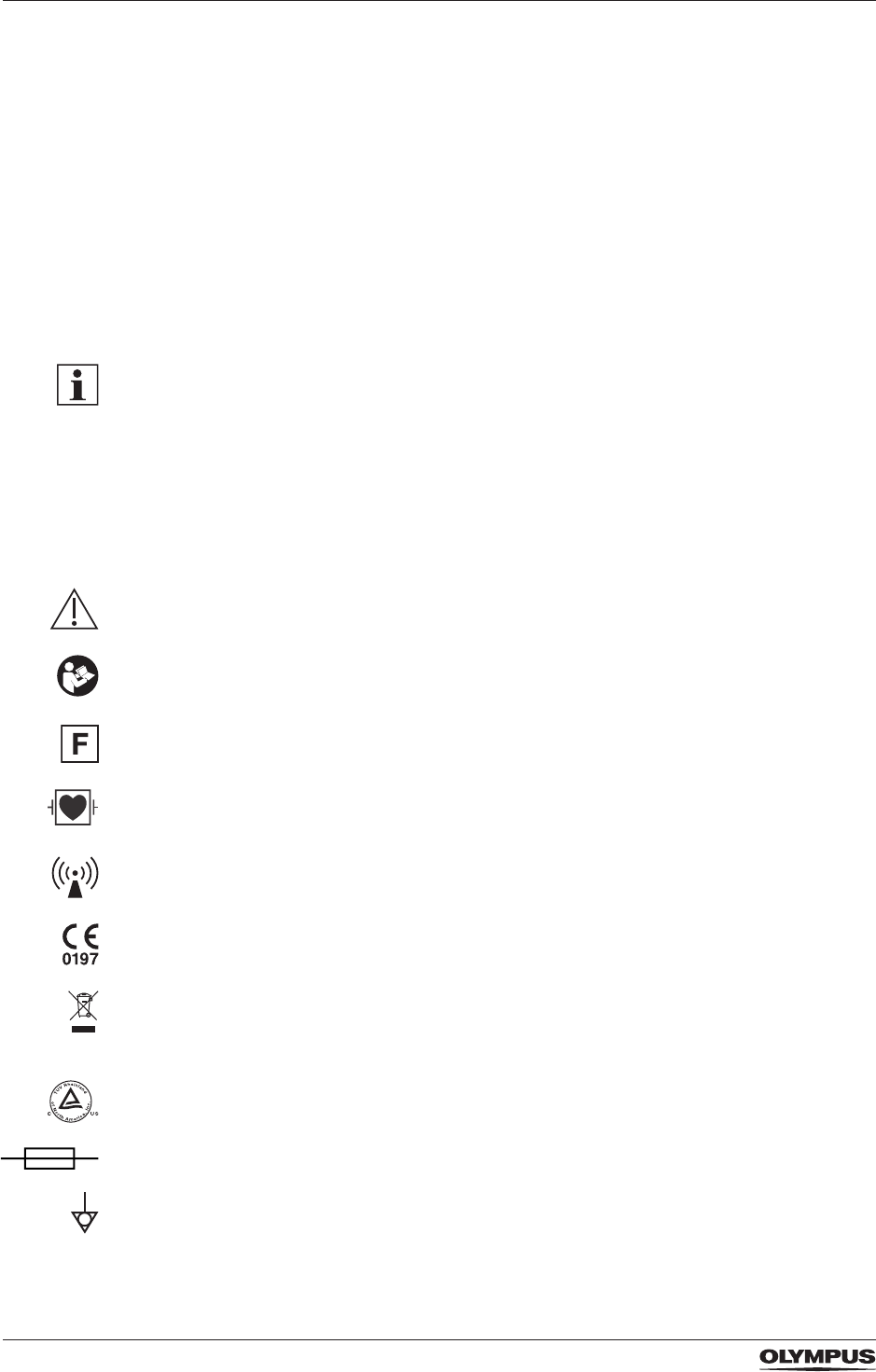
3.2 Symbols
This section gives an explanation for each symbol used on the product and on the
packaging of the product.
Caution, consult accompanying documents
Follow instructions for use
HF isolated patient circuit – symbol for patient circuit where there are no components
installed to provide a low-impedance path to earth for HF currents
Debrillation proof type CF applied part (cardiac application)
Non-ionizing electromagnetic radiation
CE certication mark – symbol for the compliance with the Medical Device Directive 93/42/
EEC
In accordance with European Directive 2002/96/EC on Waste Electrical and Electronic
Equipment, this symbol indicates that the product must not be disposed of as unsorted
municipal waste, but should be collected separately.
cTUVus certication mark
Fuse rating
Potential equalization terminal
DRAFT – 2017-01-17
21
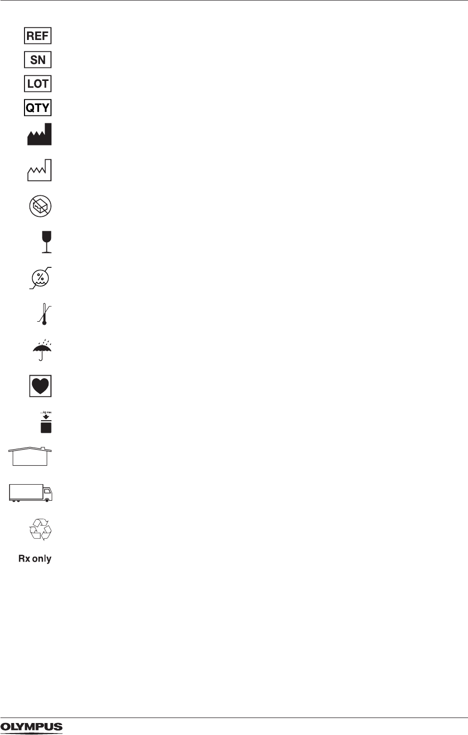
Product description and functional principles
Catalog number
Serial number
Batch code
Quantity of content
Manufacturer
Date of manufacture
Do not use if package is damaged
Fragile, handle with care
Indicates the range of humidity to which the medical device can be safely exposed
Indicates the temperature limits to which the medical device can be safely exposed
Keep away from rain. Keep dry
Type CF applied part
Indicates the stacking limit of a package by mass
Storage conditions
Transport conditions
Indicates a recovery/recyclable package or package material
Federal (USA) law restricts this device to sale by or on the order of a physician.
3.3 Nomenclature and functional principles of the software features
The electrosurgical generator is equipped with the following features:
- Contact Quality Monitor (CQM)
- High Power Cut Support (HPCS)
- Autostart
- Fast Spark Monitor (FSM)
DRAFT – 2017-01-17

22
Product description and functional principles
For selected CELON bipolar applicators the electrosurgical generator also provides:
- Radiofrequency induced thermotherapy (RFITT)
- Resistance Controlled Automatic Power (RCAP) for RFITT
- Automatic instrument recognition
- Automatic wear-out detection
The functional principles of theses features are described in the sections below.
3.3.1 CQM – Contact Quality Monitoring for the neutral electrode
When using split type neutral electrodes for monopolar electrosurgery, the CELON ELITE
ESG-200 is able to detect unintended detachment of the neutral electrode from the patient.
The indicator for the contact quality monitor (CQM) shines green while the contact between
the split type neutral electrode and the skin of the patient is within an acceptable resistance
range. If the contact between the split type neutral electrode and the patient’s skin is
insufcient, then an alarm tone sounds, a warning message is displayed and the contact
quality monitor indicator shines red.
Using non-split type neutral electrodes is not as safe as using split-type ones as CQM is not
able to detect any detachment of the neutral electrode from the patient.
For detailed information on the safe and correct use of neutral electrodes refer to the chapter
“Neutral electrode operation” on page 53.
3.3.2 HPCS – High Power Cut Support
All cutting modes are supported by HPCS. This feature optimizes the start of the cutting
procedure by applying high power to the tissue to support immediate spark ignition and to
reduce the risk of mechanical cutting.
3.3.3 Autostart for the bipolar mode SoftCoag
If the impedance is within a dened range, then Autostart feature permits automatic
activation of the output power as soon as both electrodes of the electrosurgical instrument
touch the tissue. It is possible to set a time delay so that the automatic activation does not
start immediately when the electrodes are in contact with the tissue but only after a certain
time. Consequently, activating by foot switch is not necessary.
Autostart is available only for the bipolar mode SoftCoag.
3.3.4 FSM – Fast Spark Monitor
This feature ensures smooth and reproducible cutting although the tissue characteristic are
varying, e.g. in muscle and fat.
3.4 Features for selected CELON bipolar applicators
The following features are compatible only with selected CELON bipolar applicators, e.g.
CelonProSleep plus or CelonProBreath.
DRAFT – 2017-01-17

23
Product description and functional principles
3.4.1 RFITT – Radiofrequency induced thermotherapy
The medical purpose of the radiofrequency induced thermotherapy, RFITT, is to achieve
controlled tissue coagulation. The CELON ELITE ESG-200 offers 4 different RFITT modes
that are used in conjunction with the CELON bipolar applicators. For further information refer
to the section “The bipolar RFITT coagulation modes” on page 63.
3.4.2 RCAP – Resistance Controlled Automatic Power for RFITT
RCAP is a feature that supports the mode Strong RFITT. Deep tissue coagulation without
signicant desiccation is achieved with RCAP.
RCAP determines the maximum power uptake of the tissue, adapted to the momentary
treatment status and automatically adjusts the electrosurgical generator. For this process,
the geometry of the bipolar applicator used as well as individual tissue characteristics,
e.g. blood perfusion, are taken into account. Therefore, premature tissue desiccation
is effectively avoided and subsequent manual adjustment of the supplied power is
unnecessary. Also refer to the section “The bipolar RFITT coagulation modes” on page
63.
3.4.3 Automatic instrument recognition
The electrosurgical generator is equipped with a radio transmitting and receiving technology.
Therefore, the selected CELON bipolar applicator that is connected to the electrosurgical
generator is recognized automatically. This means:
- The name of the connected CELON bipolar applicator is displayed in the BIPOLAR pane
of the touch screen, e. g. [ProBreath] or [ProSleep plus].
- Only compatible modes and output power settings are available.
- The user can select one of these compatible modes and can change the output power
level within a restricted range.
Other radio transmitters and receivers, e. g. mobile phones, may interfere with the automatic
instrument recognition.
• To avoid interference observe the instructions in the chapter “Electromagnetic
compatibility” on page 92.
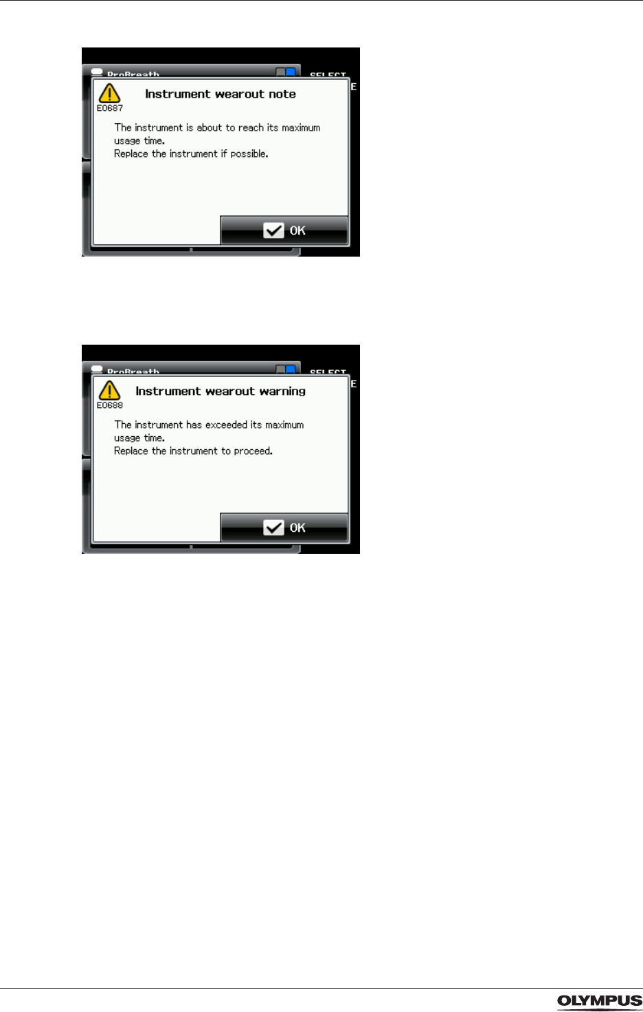
3.4.4 Automatic wear-out detection
To protect the patient from a worn-out instrument the bipolar applicators are equipped with
memory chips that record the usage. When the permitted usage span is nearly reached,
the electrosurgical generator alerts the user by emitting an alarm tone and displaying the
following error message:
DRAFT – 2017-01-17
24
Product description and functional principles
At this stage and as soon as the treatment situation allows, the user needs to replace the
bipolar applicator.
When the permitted usage span is exceeded, the following error message is displayed:
When this error message is displayed, it is impossible to activate the bipolar applicator
anymore.
DRAFT – 2017-01-17
25
Product description and functional principles
3.5 Nomenclature and functional principles of the hardware
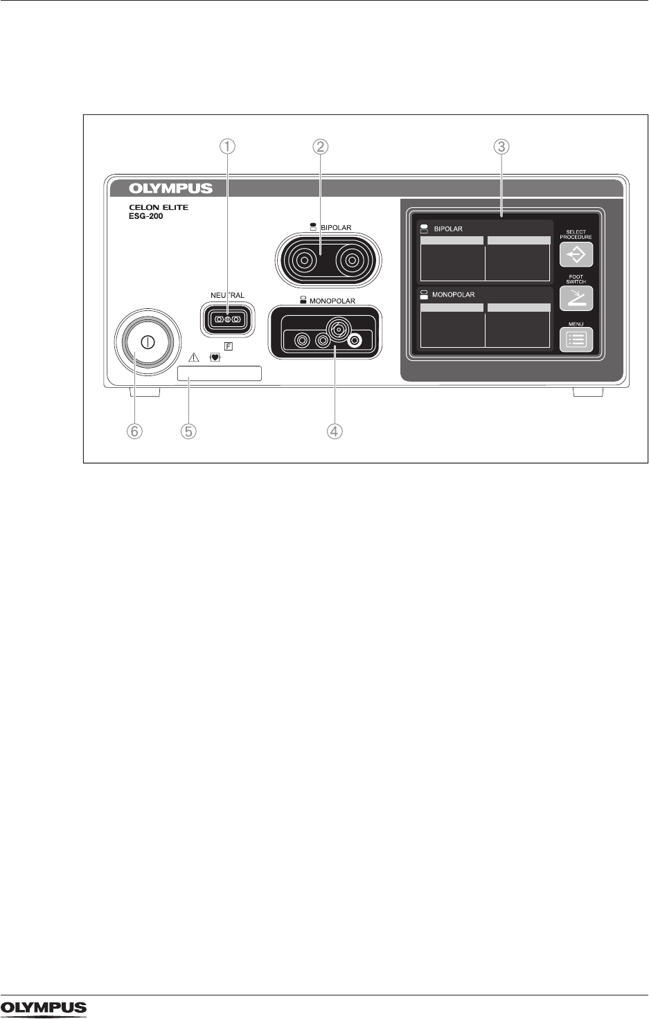
3.5.1 The front panel
Figure 3.1 Front panel of the CELON ELITE ESG-200
1) *Neutral electrode socket
To connect a neutral electrode.
2) *BIPOLAR output socket
To connect a bipolar HF instrument.
3) Touch screen
To display the status of connected accessories.
To show and modify settings.
4) *MONOPOLAR output socket
To connect a monopolar HF instrument.
5) UDI (unique device identier)
6) Power switch
To switch the electrosurgical generator on and off.
*Applied part according to standard IEC 60601-1.
DRAFT – 2017-01-17
26
Product description and functional principles
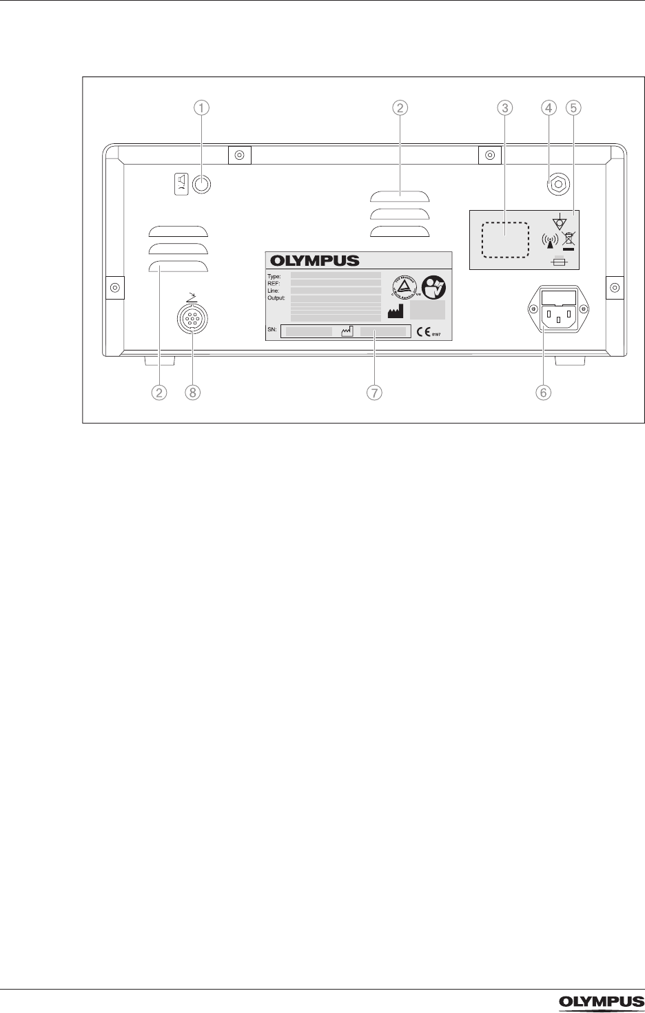
3.5.2 The rear panel
Figure 3.2 Rear panel
1) Volume control
To adjust the volume of the output tone.
2) Ventilation slots
3) Place holder for country specic RFID symbol and registration number
Only applicable for specic countries. Not applicable for the European Union.
4) Equipotential bonding point
To increase electrical safety by potential equalization
5) Symbol plate
6) Power socket with fuse holder
7) Rating plate
8) Foot switch socket
To connect the double pedal foot switch.
DRAFT – 2017-01-17
27
Product description and functional principles
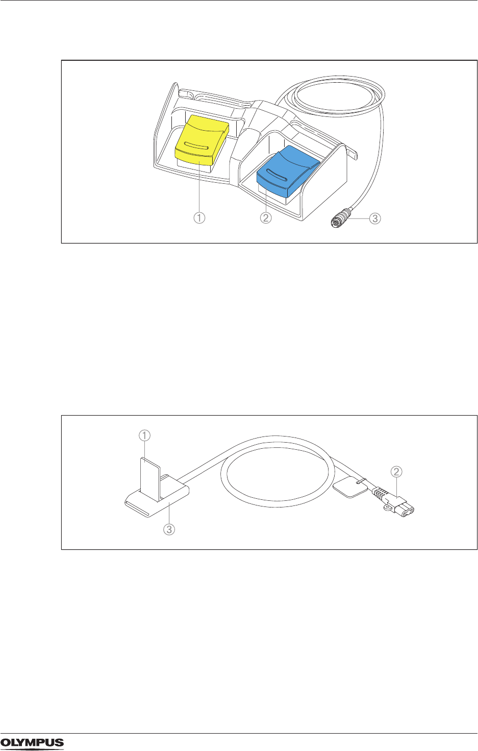
3.5.3 The double pedal foot switch
Figure 3.3 Double pedal foot switch
1) Cut pedal (yellow)
To activate the selected cutting mode.
2) Coagulation pedal (blue)
To activate the selected coagulation mode.
3) Foot switch plug
To connect the foot switch to the foot switch socket.
3.5.4 The connecting cable for the neutral electrode
This cable is not included in the delivery scope and may be purchased separately.
Figure 3.4 Cable for neutral electrode, MAJ-814
1) Locking lever
To lock the neutral electrode in the clamp.
2) Plug to front panel of electrosurgical generator
To connect the neutral electrode to the neutral electrode socket.
3) Clamp
To connect the neutral electrode to the cable.
DRAFT – 2017-01-17
28
Product description and functional principles
3.6 Nomenclature and functional principles of the touch screen
The electrosurgical generator is equipped with a user friendly touch screen. The control
buttons are activated by tapping the corresponding part on the screen with the nger tip.
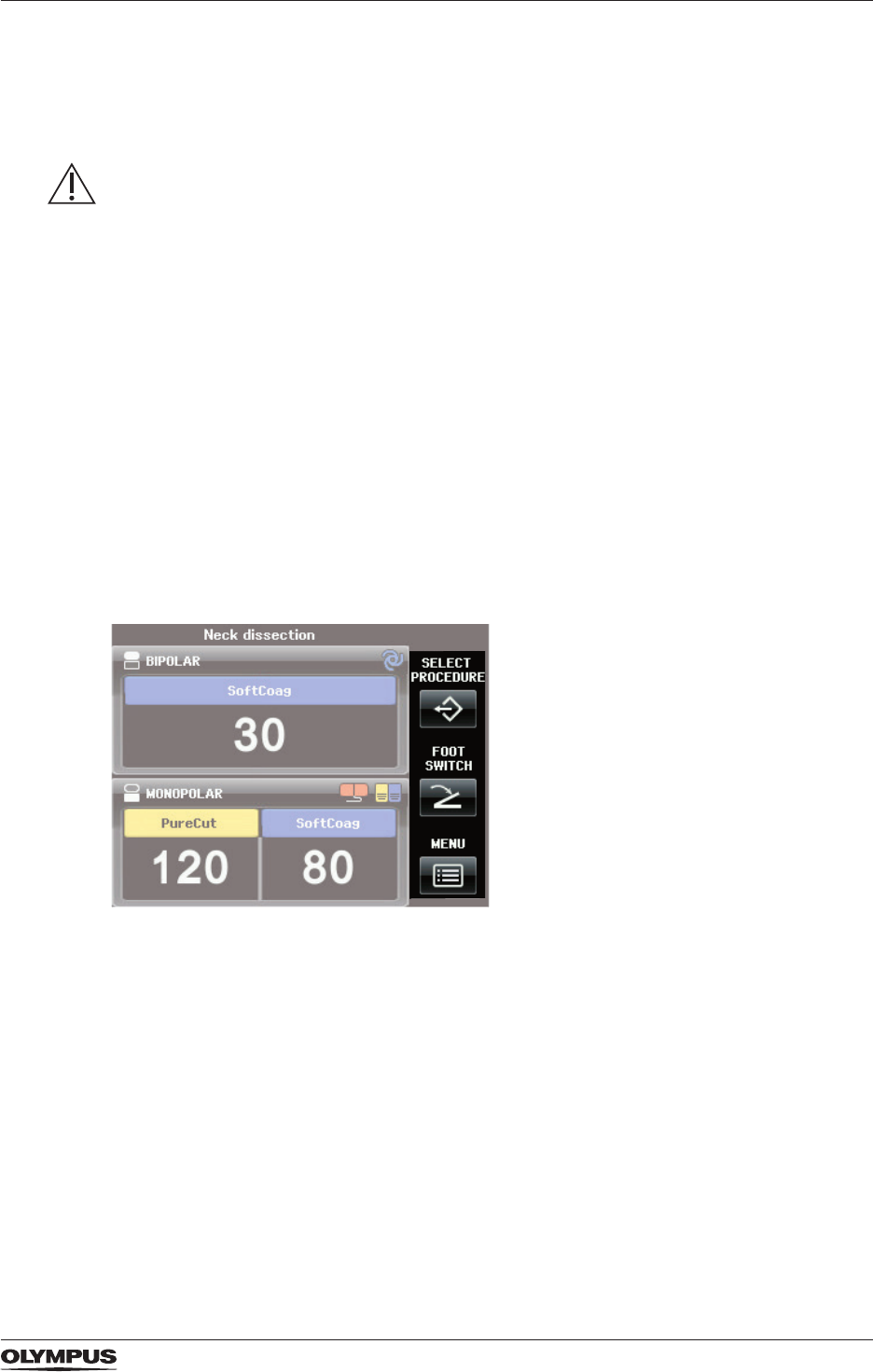
3.6.1 The All Screen
The All Screen is the initial screen of the electrosurgical generator. The All Screen displays
the current settings of the selected modes as well as the 3 buttons on the right-hand side for
system settings.
MONOPOLAR pane, BIPOLAR pane and buttons for system settings
Each pane covers all output socket related information as described below. Tap into the
pane to switch to the corresponding Set Screen. On the Set Screen the mode and the output
power levels for the corresponding output socket can be set.
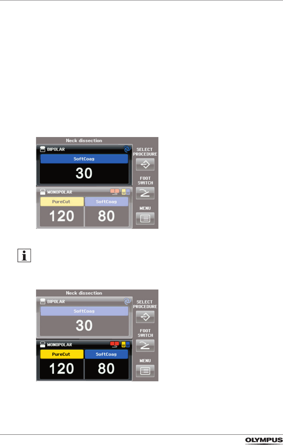
Figure 3.5 BIPOLAR pane
As a default setting the cutting modes for the BIPOLAR socket are switched off, i.e. only the
blue coagulation button is displayed in the BIPOLAR pane. It is impossible to access and
activate any bipolar cutting mode.
• To switch on the bipolar cutting modes refer to the section “Bipolar Cut Setup” on page
46.
Figure 3.6 MONOPOLAR pane
DRAFT – 2017-01-17
29
Product description and functional principles
Figure 3.7 Buttons for system settings
Single elements of the All Screen
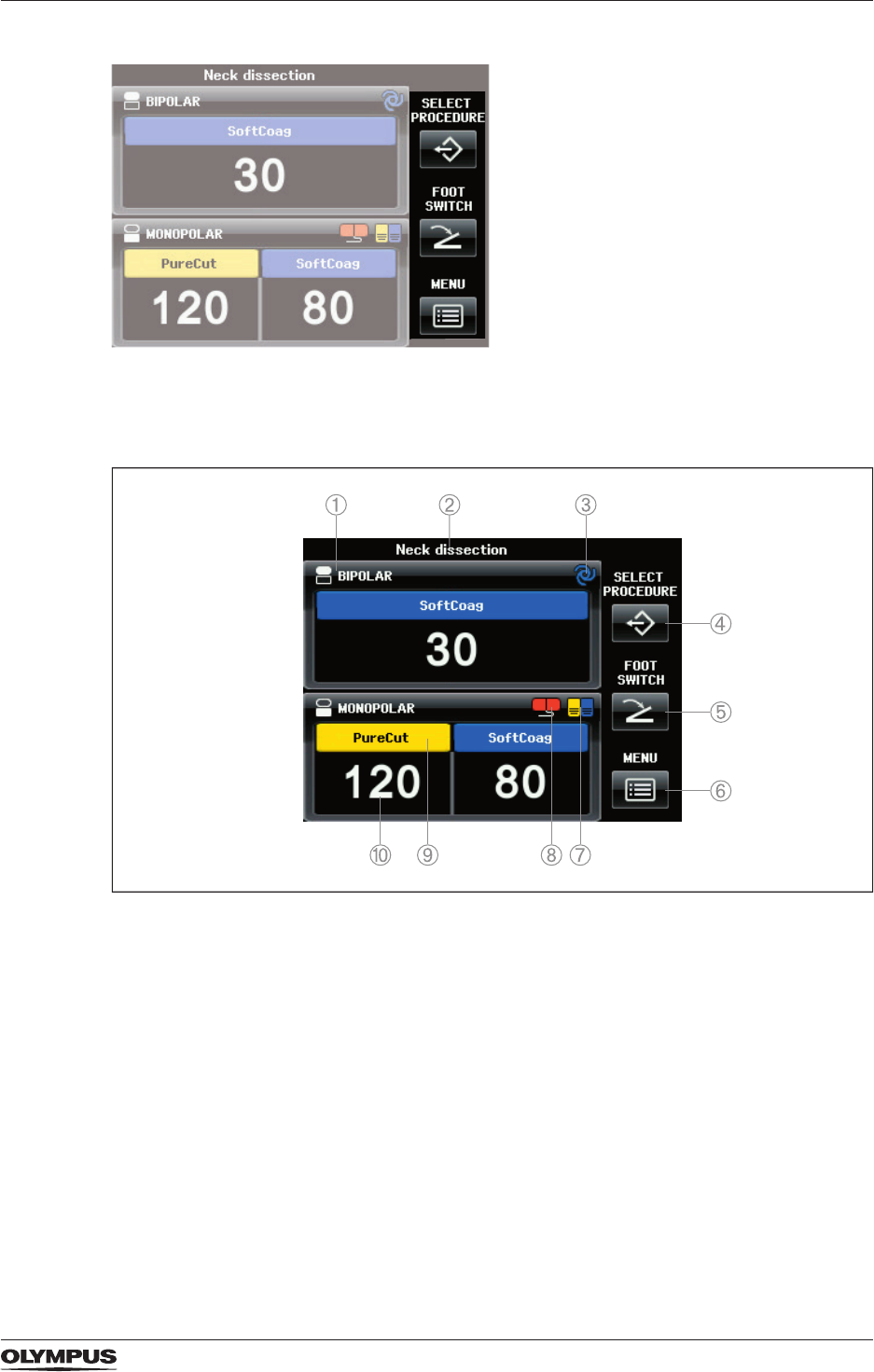
Figure 3.8 Buttons and symbols on the All Screen
1) Output socket indicator and output socket name
Displays the symbol and the name of the corresponding output socket.
2) Procedure name
Displays the selected procedure. If no procedure is selected, then this line is blank.
3) Autostart indicator
Indicates that the Autostart feature is assigned to the corresponding output socket.
4) Button [SELECT PROCEDURE]
To open the screen [Select Procedure screen] for recalling saved settings.
5) Button [FOOT SWITCH]
To open the screen [Assign Foot Switch] for assigning the foot switch or the Autostart
feature to an output socket.
6) Button [MENU]
To open the screen [Select Menu] for controlling several functions.
7) Foot switch indicator
Indicates that a foot switch is assigned to the corresponding output socket.
DRAFT – 2017-01-17
30
Product description and functional principles
8) CQM indicator for neutral electrodes
Indicates the connection status of a neutral electrode.
9) Mode name
Displays the selected mode.
10) Output power level
Displays the selected output power level.
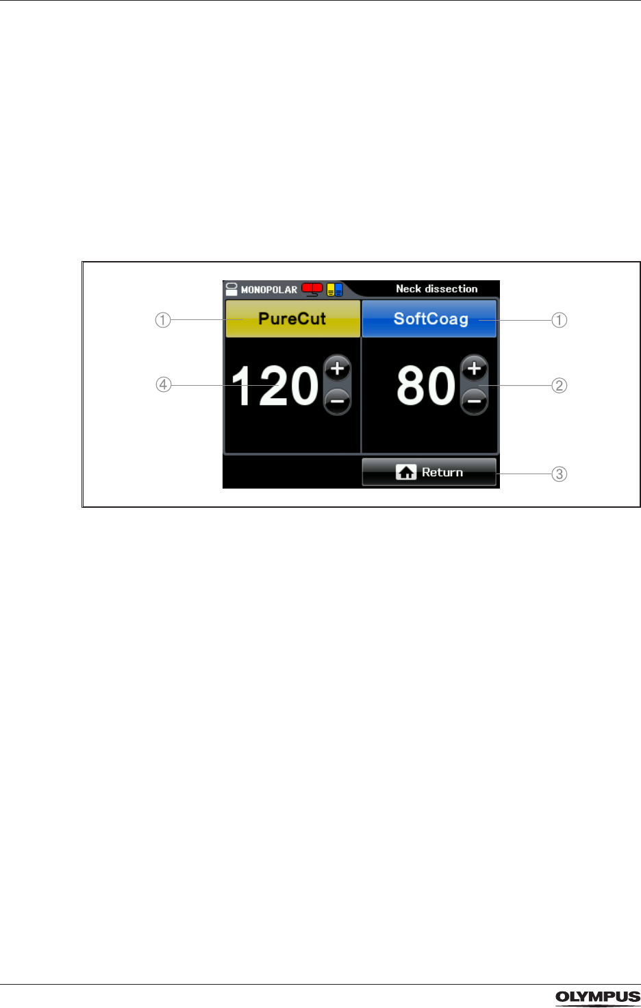
3.6.2 The Set Screen
On the Set Screen the mode and the output power levels for the corresponding output
socket are set. The Set Screen is displayed when tapping into the pane [BIPOLAR] or
[MONOPOLAR] on the All Screen.
Figure 3.9 Set Screen
1) Mode button
Displays the name of the output mode as selected in the Mode Screen.
2) Plus and minus button
To increase and decrease the level of output power.
3) Return button
To save the settings and to return to the All Screen.
4) Output power level
To show the selected level of output power.
DRAFT – 2017-01-17
31
Product description and functional principles
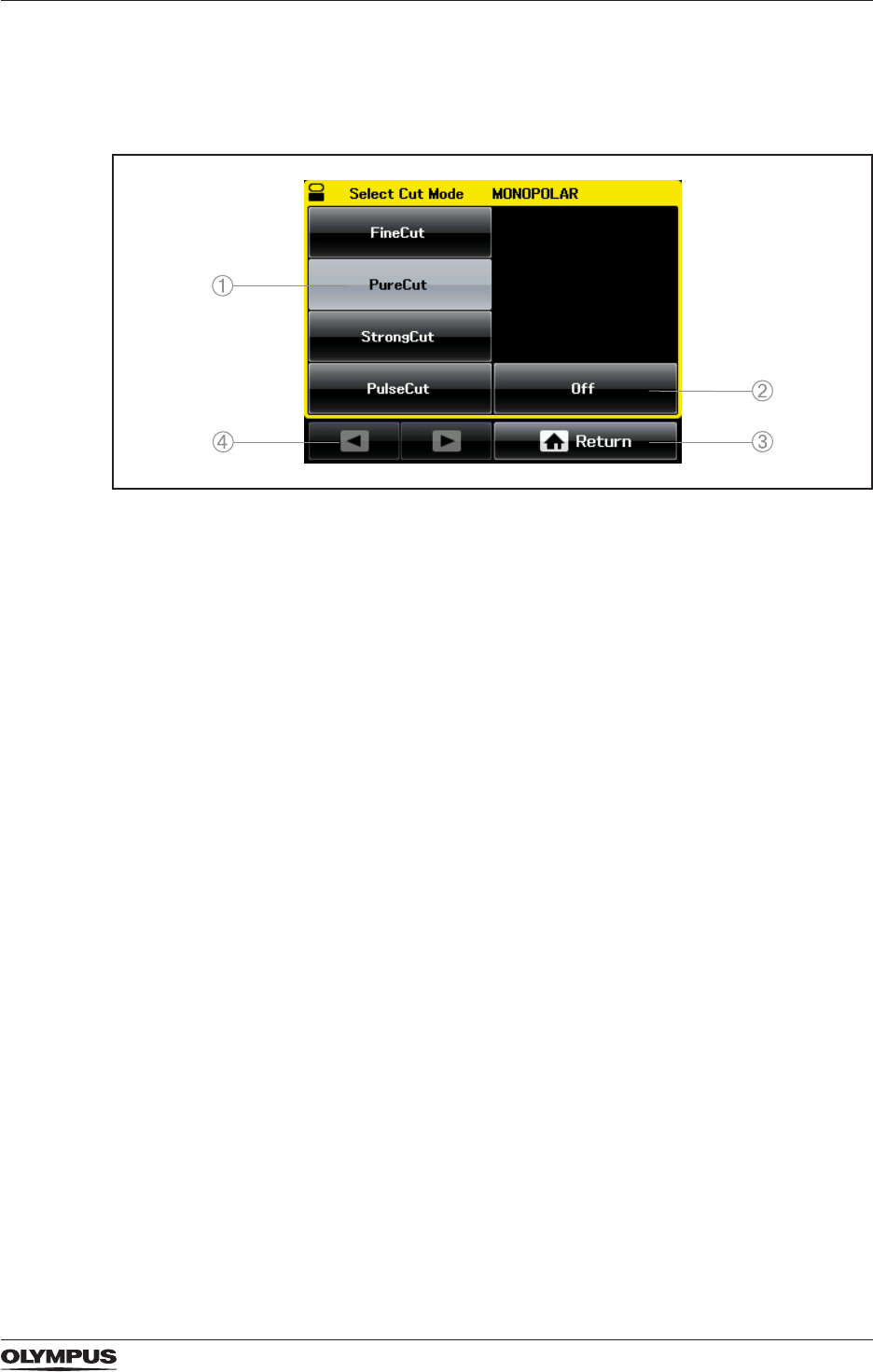
3.6.3 The Mode Screen
On the Mode Screen the output mode is selected. The Mode Screen is displayed when
tapping either the yellow area (cut) or blue area (coagulation) on the Set Screen.
Figure 3.10 Mode Screen for monopolar cutting
1) Mode buttons
To select a mode for the corresponding output socket (BIPOLAR or MONOPOLAR).
2) Button [Off]
To completely deactivate cutting/coagulation for the output socket (BIPOLAR or
MONOPOLAR).
3) Return button
To return to the Set Screen.
4) Arrow buttons
To browse the pages of the Mode Screen.
3.6.4 The screens for system settings
The 3 buttons on the right-hand side of the All Screen give access to the settings of the
following screens:
- Select Procedure
- Assign Foot Switch
- Select Menu
DRAFT – 2017-01-17
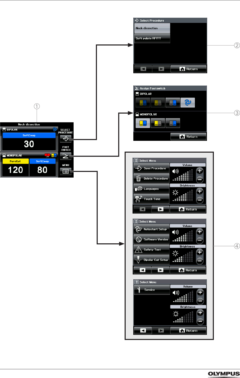
32
Product description and functional principles
Figure 3.11 Hierarchy list of the 3 right-hand sided buttons on the All Screen
DRAFT – 2017-01-17
33
Product description and functional principles
1) All Screen
2) Screen [Select Procedure]
3) Screen [Assign Foot Switch]
4) Screen [Select Menu]
For detailed information on system settings refer to the chapter “System settings” on page
39.
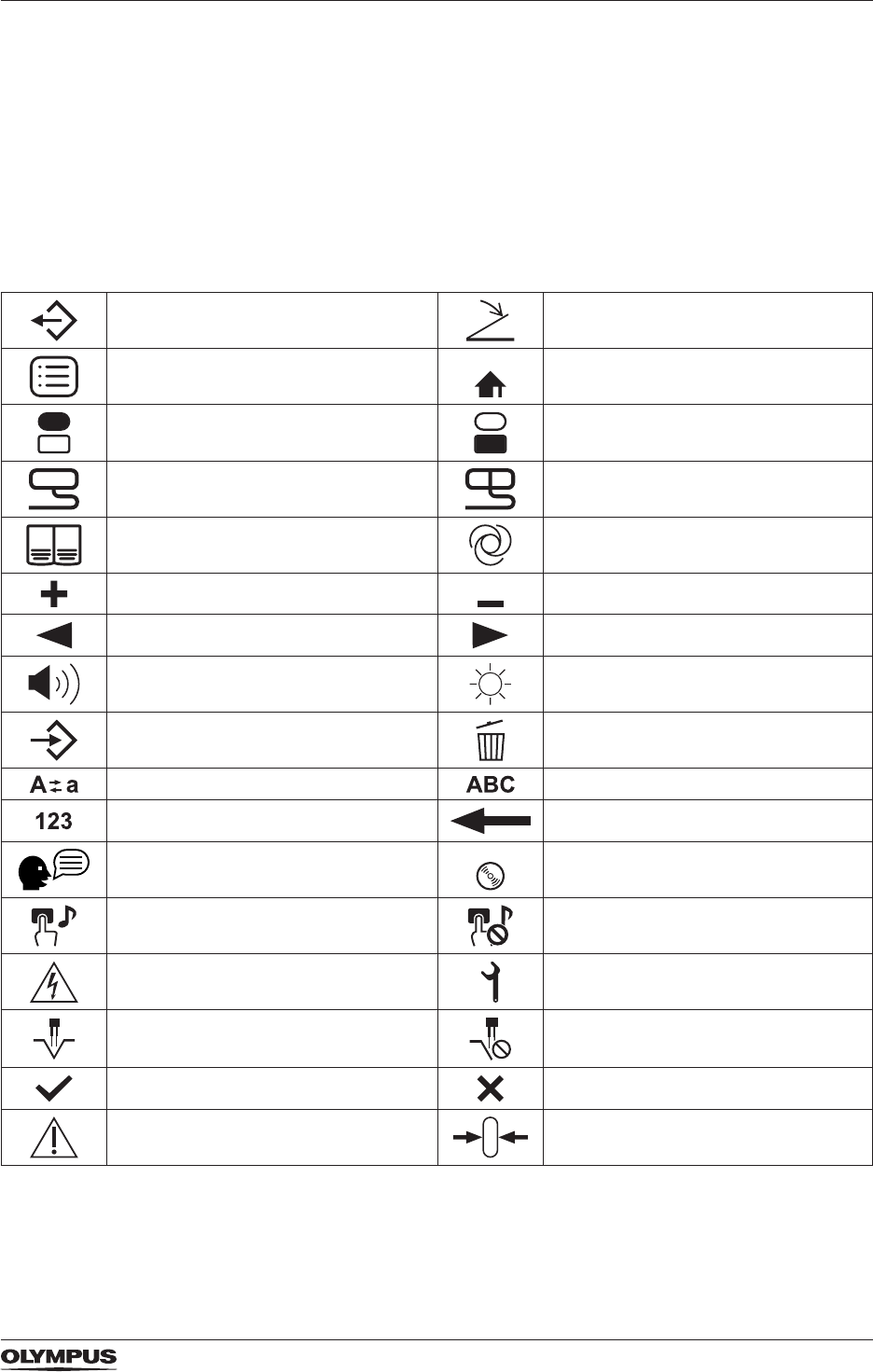
3.6.5 Icons displayed on the touch screen
SELECT PROCEDURE FOOT SWITCH
MENU Return
BIPOLAR output socket MONOPOLAR output socket
Non-split type neutral electrode Split type neutral electrode
Double pedal foot switch Autostart
Plus Minus
Previous Next
Volume Brightness
Save Procedure Delete procedure
Upper case/lower case Alphabetic
Numeric Back space
Languages Software version
Touch tone on Touch tone off
Safety test Service
Bipolar cutting on Bipolar cutting off
OK Cancel
Caution Reset
Table: Icons displayed on the touch screen
DRAFT – 2017-01-17

34
Product description and functional principles
3.7 Warranty
Any warranty claims towards Olympus are forfeited if the user or unauthorized persons
attempt repair or modication of the product. No warranty is provided for any damage due to
misuse of the product.
DRAFT – 2017-01-17

35
Installation
4 Installation
4.1 General inspection
Before installing and connecting, inspect the electrosurgical generator and its equipment as
follows:
• Check that the electrosurgical generator, its equipment and all accessories do not have:
- any dents, cracks, kinks, or deformations
- any deep scratches
- any corrosion
- any missing or loose parts
• Check all markings on the electrosurgical generator, its equipment and all accessories for
clear visibility.
4.2 Placement of the electrosurgical generator
To prevent malfunction or damage of the electrosurgical generator and its accessories take
account of the following circumstances when placing the electrosurgical generator:
• Place the electrosurgical generator on a stable, level surface.
• Put the electrosurgical generator upright onto its feet. Do not install the electrosurgical
generator on its side or upside down.
• If the electrosurgical generator is placed on a trolley, the trolley must be of adequate
strength and size to hold the electrosurgical generator securely.
• Make sure that there is sufcient space at the back of the electrosurgical generator to
allow air circulation at the ventilation slots.
• Only use the electrosurgical generator in compliance with the environmental conditions as
specied in the chapter “Specications” on page 90.
• When lifting up, grip the electrosurgical generator at its sides with both hands. Do not hold
the electrosurgical generator at its fuse holder.
Interference and automatic instrument recognition
The electrosurgical generator is equipped with a radio transmitting and receiving technology.
Other radio transmitters and receivers, e. g. mobile phones, may interfere with the automatic
instrument recognition.
• To avoid interference observe the instructions in the chapter “Electromagnetic
compatibility” on page 92.
4.3 Connecting the electrosurgical generator to the mains electricity
WARNING
Electric shock
In case that a damaged electrosurgical generator is connected inadequately to the mains
electricity, there is the risk that internal electrical components conduct voltage to the
housing. This could result in electric shock to the user.
• Connect the mains plug of the cord set directly to a grounded xed socket-outlet.
• If a multiple socket-outlet is used take account of the following:
• The multiple socket-outlet must be equipped with an insulating transformer of
protection class I, conforming to IEC 60601-1.
• Observe the maximum permitted current or power loading of the multiple socket-outlet
and the insulating transformer.
DRAFT – 2017-01-17
36
Installation
WARNING
Device blackout
Be aware that the electrosurgical generator immediately turns off if the mains plug
is disconnected or if the fuses blow. During a procedure, this could result in severe
complications for the patient.
• Make sure that the mains plug is securely connected to the socket-outlet.
• Do not place portable socket-outlets on the oor to avoid trip hazards which could unplug
the cord set.
• Only use power cords as specied in the section “Specications for the cord set” on page
91.
• Make sure that the circuit breaker is sufcient for the power requirements of the
electrosurgical generator and additional equipment.
4.3.1 Before connecting
• Make sure that the xed socket-outlet is grounded.
Only connect the electrosurgical generator to a grounded xed socket-outlet.
• Make sure that the xed socket-outlet meets the power requirements as specied on the
rating plate of the electrosurgical generator.
Only connect the electrosurgical generator if the power specications of the xed socket-
outlet match the specications on the rating plate.
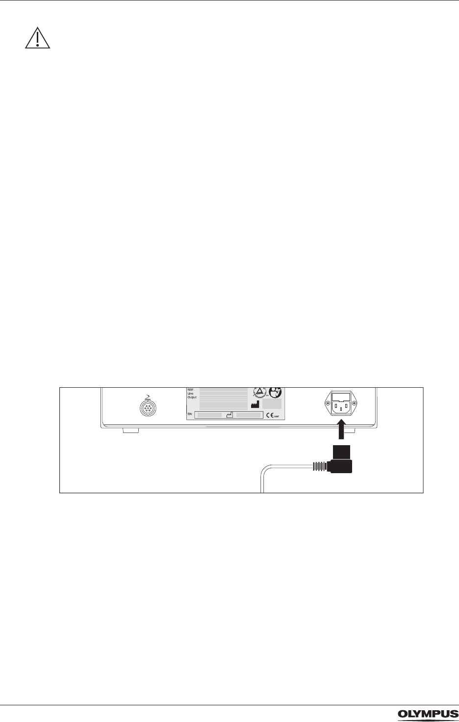
4.3.2 Connecting
To connect the electrosurgical generator to the mains electricity proceed as follows:
1. Make sure that the electrosurgical generator is turned off, i.e. the power switch must not
be depressed.
Figure 4.1 Connecting the cord set to the electrosurgical generator
2. Connect one plug of the cord set to the power socket on the rear panel of the ESG-200.
3. Connect the other plug of the cord set to the socket-outlet of the mains electricity.
Equipotential bonding point
The purpose of additional equipotential bonding is to equalise potentials between different
metal parts that can be touched simultaneously in the medical environment. Equipotential
bonding increases electrical safety.
• Connect the pin at the rear panel of the electrosurgical generator to an equipotential
bonding lead, which should be provided by the hospital's technical department.
DRAFT – 2017-01-17

37
Installation
4.4 Connecting the double pedal foot switch
WARNING
Secure connection of the plug
If the foot switch plug is not connected securely, then the energy output may not be
activated. There is the risk that the HF instrument cuts tissue mechanically. This could result
in bleeding and perforation of the tissue.
• Securely connect the foot switch plug to the foot switch socket at the electrosurgical
generator as described below.
CAUTION
Not waterproof
The foot switch plug is not waterproof. Any liquid, e.g. water, that gets into the plug can
damage the foot switch.
• Take care that the foot switch plug does not get wet.
CAUTION
Proper disconnection of the plug
Tugging and pulling at the foot switch cable can break the electric circuit and can damage
the foot switch.
• When disconnecting the foot switch plug, directly pull at the plug.
• Do not tug or pull at the cable.
CAUTION
Compatible foot switch
If a non-compatible foot switch is connected to the electrosurgical generator, then the foot
switch might not function correctly. This could cause equipment damage which might result
in patient injury.
• Only use the compatible foot switch (WB50402W) which is within the scope of delivery.
4.4.1 Before connecting
• Inspect the foot switch and its cord set for scratches, cracks, and other damages.
Do not use the foot switch if any kind of damage is observed.
• Check that the each pedal of the foot switch runs smoothly.
Do not use the foot switch if any kind of problem with the pedals is observed.
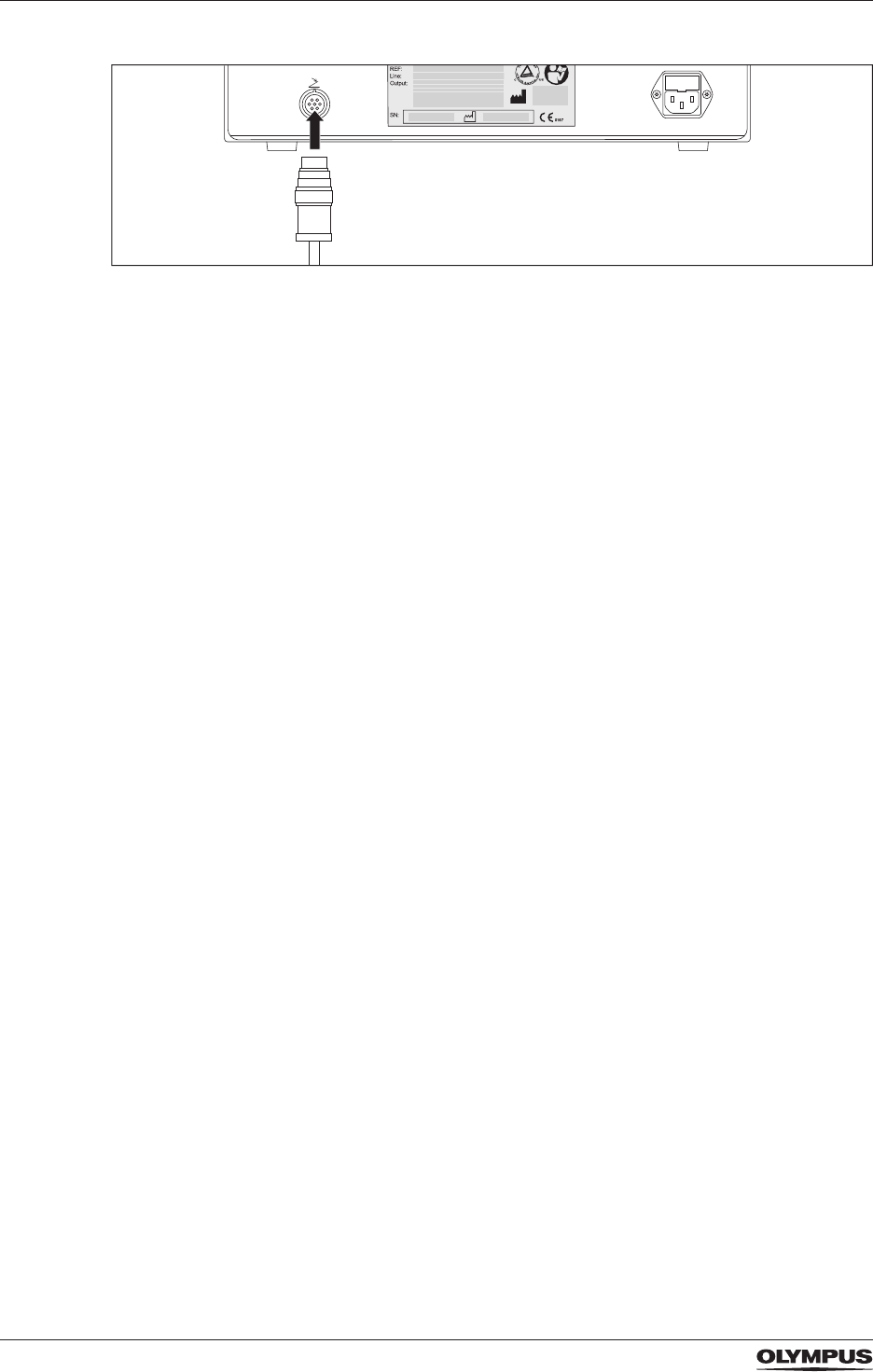
4.4.2 Connecting
To connect the double pedal foot switch to the electrosurgical generator proceed as follows:
1. Correctly align the pins inside the foot switch plug with the receptacles of the foot switch
socket.
DRAFT – 2017-01-17
38
Installation
Figure 4.2 Connecting the foot switch to the electrosurgical generator
2. Insert the foot switch plug into the foot switch socket.
3. Rotate the retaining ring clockwise until it is completely tight.
DRAFT – 2017-01-17
39
System settings
5 System settings
5.1 Operation of the touch screen
CAUTION
Operation of the touch screen
Wrong operation of the touch screen can cause malfunction or damage to the touch screen.
• Only tap one button or pane at a time.
• Only tap the touch screen from the front. Avoid oblique angles when tapping the touch
screen.
• Do not use pointed objects, e.g. a pen, to tap the touch screen.
• Do not tap the touch screen unintentionally.
• Do not apply excessive loads on the surface of the touch screen.
• Remove dust and dirt by wiping the touch screen with a cloth.
Operator's position
- The operator of the touch screen must be in front of the electrosurgical generator.
- For parameter settings the viewing distance must not exceed 50 cm.
- For watching the touch screen the viewing distance must not exceed 100 cm.
- All viewing angles, i.e. left, right, upper, lower angle, must not exceed 70°.
5.2 Overview of system settings
Figure 5.1 Buttons for system settings
The 3 buttons on the right-hand side of the All Screen give access to various system
settings. The following table gives a short introduction to system settings. Detailed
information on the single settings are give in the following sections.
DRAFT – 2017-01-17
40
System settings
Buttons Function
SELECT
PROCEDURE
Selecting previously saved, preferred settings.
FOOT
SWITCH
Assigning the foot switch and Autostart.
MENU Save Procedure Saving or overwriting of output settings.
Delete Procedure Deleting previously saved settings.
Languages Selecting the preferred language.
Available languages: English, Japanese, German,
Chinese, French, Italian, Spanish and Portuguese.
Touch Tone Activating or deactivating the audible feedback when
tapping the touch screen.
Autostart Setup Setting a time delay for Autostart.
Software Version Showing information about the installed software
version.
Safety Test Opening or closing the output relays. Required for
the annual safety check.
Bipolar Cut Setup Switching the cutting modes for the BIPOLAR
socket on or off.
Service Accessing the service screen. For the technical
service only. This screen is password protected.
Volume control for
output tone
Increasing or decreasing of the volume of the output
tone.
Brightness control Increasing or decreasing of the brightness of the
touch screen.
Table: Overview of system settings
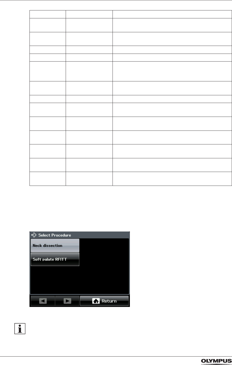
5.3 Select Procedure settings
Use this function to select procedure settings that were saved previously.
Figure 5.2 Screen [Select Procedure]
There are no factory settings provided for this function. If no settings are saved, the
message [No procedure saved] is displayed on the screen [Select Procedure]. Refer to the
section “Save Procedure - Saving and overwriting procedure settings” on page 42.
DRAFT – 2017-01-17
41
System settings
To select one of the saved procedure settings proceed as follows:
1. Tap [SELECT PROCEDURE] on the All Screen.
- The screen [Select Procedure] is displayed with a list of saved procedure settings.
- An already selected procedure is indicated by a highlighted button.
- If no procedure settings are saved, the message [No procedure saved] is displayed.
• To return to the All Screen tap [Return].
2. Tap the button of the procedure to be selected.
- The All Screen is displayed which shows the settings of the selected procedure.
- In the headline of the All Screen the name of the selected procedure is displayed.
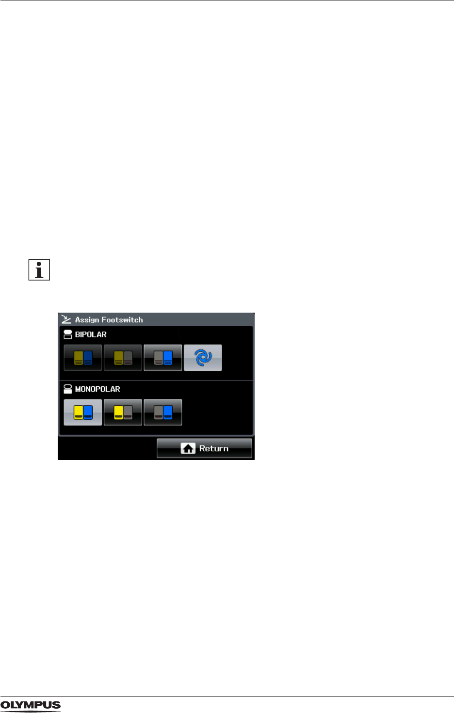
5.4 Foot switch assignment and Autostart
Foot switch pedals
Use this function to assign the double pedal foot switch either to the BIPOLAR output
socket or to the MONOPOLAR output socket. It is also possible to assign one pedal of the
foot switch to the BIPOLAR output socket and the other pedal to the MONOPOLAR output
socket.
As a default setting the cutting modes for the BIPOLAR socket are switched off. Therefore, it
is impossible to assign the yellow cut pedal to the BIPOLAR socket.
• To switch on the bipolar cutting modes refer to the section “Bipolar Cut Setup” on page
46.
Figure 5.3 Screen [Assign Foot Switch]
Autostart and time delay
For the bipolar mode SoftCoag the feature Autostart can be assigned to the BIPOLAR
output socket. Refer to the sections “Autostart for the bipolar mode SoftCoag” on page 22
and “Autostart Setup” on page 45.
Highlighted buttons
The chosen assignments are indicated by highlighted buttons. The gure above shows that
Autostart is assigned to the BIPOLAR output socket. To the MONOPOLAR output socket,
both pedals of the foot switch are assigned. If the foot switch is not connected properly, then
no button is highlighted and it is impossible to assign the foot switch or Autostart.
To assign the foot switch or Autostart to the output sockets proceed as follows:
1. Tap [FOOT SWITCH] on the All Screen.
DRAFT – 2017-01-17
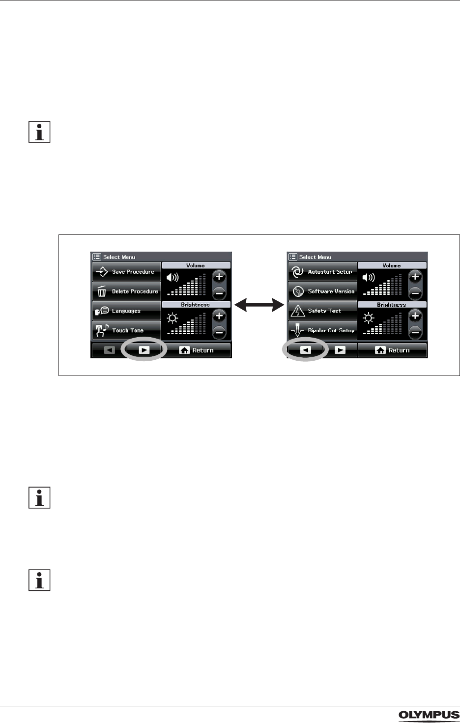
42
System settings
The screen [Assign Foot Switch] is displayed.
2. In the BIPOLAR pane of the screen tap the button for the required function, i.e. double
pedal, only yellow pedal, only blue pedal or Autostart.
3. In the MONOPOLAR pane tap the button for the required foot switch, i.e. double pedal,
only yellow pedal or only blue pedal.
4. Tap [Return] to conrm the settings.
The All Screen is displayed.
Limited power for Autostart
If the output power level is above 50 when selecting Autostart, then the output power level is
reduced to 50 automatically.
5.5 Select Menu settings
Use this function to adjust the menu settings as summarized in the table “Overview of
system settings” on page 39.
Figure 5.4 Screen [Select Menu]
When opening the screen [Select Menu] there are 2 arrow buttons at the bottom.
1. Tap [MENU] on the All Screen.
The screen [Select Menu] is displayed.
2. Use the arrow buttons to browse back and forth between the pages of the screen [Select
Menu].
Cancel button
For most of the following menu settings it is possible to interrupt the operation by tapping
[Cancel] until the screen [Select Menu] is displayed again.
5.5.1 Save Procedure - Saving and overwriting procedure settings
The delay for Autostart cannot be saved within a procedure setting.
Use this function to save all output settings that are currently displayed on the All Screen
under a certain procedure name. In detail this is:
- The bipolar modes for cutting and coagulation and their output levels.
- The monopolar modes for cutting and coagulation and their output levels.
- The assignment of the foot switch or Autostart for the bipolar mode SoftCoag.
It is possible to save up to 39 different procedure settings and to overwrite existing settings.
DRAFT – 2017-01-17
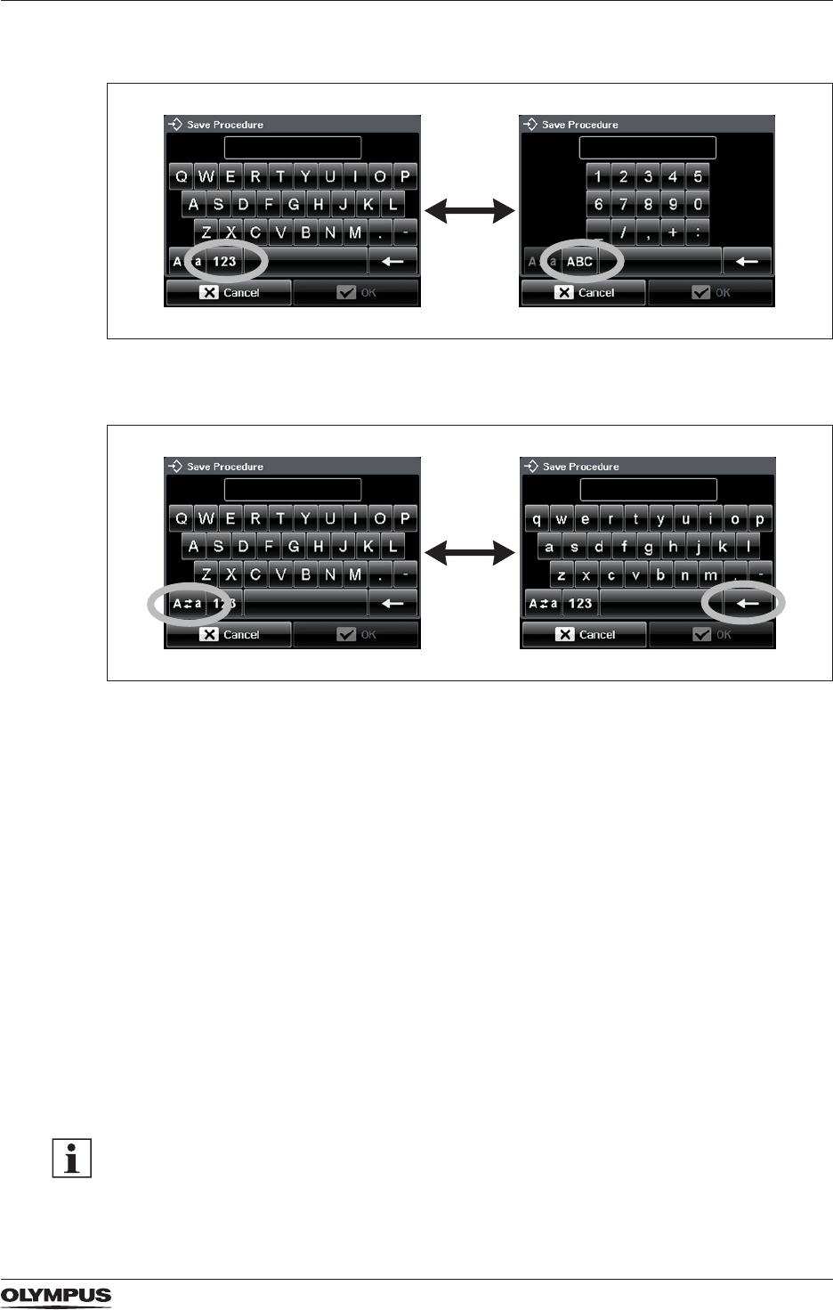
43
System settings
The onscreen keyboard
Figure 5.5 Onscreen keyboard (letters and numbers)
• To switch between letters and numbers tap [123] or [ABC] at the bottom of the keyboard.
Figure 5.6 Onscreen keyboard (upper/lower key and backspace key)
• To switch between upper-case letters and lower-case letters tap the shift key at the bottom
left of the keyboard.
• To delete characters tap the backspace key on the bottom right of the keyboard.
Saving a new procedure setting
To save the current output settings proceed as follows:
1. Tap [MENU] on the All Screen.
The screen [Select Menu] is displayed.
2. Tap [Save Procedure].
The screen [Save Procedure] is displayed.
3. Tap [New Procedure].
The screen changes to an onscreen keyboard.
4. Enter a name for the procedure setting.
5. Tap [OK] to save the procedure name.
- A message box is displayed which conrms that the procedure settings are saved.
- Then the All Screen is displayed.
- In the headline of the All Screen the procedure name is displayed.
If a procedure name already exists, then a message box is displayed that asks for
conrmation to overwrite the existing procedure settings. Refer to the section below.
DRAFT – 2017-01-17

44
System settings
Overwriting a procedure setting
1. Tap [MENU] on the All Screen.
The screen [Select Menu] is displayed.
2. Tap [Save Procedure].
The screen [Save Procedure] is displayed.
3. Use the arrow buttons to browse back and forth the pages of the screen.
4. Tap the name of the procedure settings to be overwritten.
A message box with a request for conrmation is displayed.
5. To overwrite the existing procedure settings tap [OK] in the message box.
- Another message box is displayed which conrms that the procedure settings are
saved.
- Then the All Screen is displayed.
5.5.2 Delete Procedure
To delete an existing procedure setting from the memory proceed as follows:
1. Tap [MENU] on the All Screen.
The screen [Select Menu] is displayed.
2. Tap [Delete Procedure].
The screen [Delete Procedure] is displayed.
3. Use the arrow buttons to browse back and forth the pages of the screen.
4. Tap the procedure name of the settings to be deleted.
A message box with a request for conrmation is displayed.
5. Tap [OK] to delete the procedure settings.
- Another message box is displayed which conrms that the procedure settings are
deleted.
- Then the screen [Select Menu] is displayed.
5.5.3 Languages
Use the language function to select the preferred language. The text on the touch screen
can be displayed in 8 different languages:
- English
- German
- French
- Italian
- Japanese
- Chinese
- Spanish
- Portuguese
To select the preferred language proceed as follows:
1. Tap [MENU] on the All Screen.
The screen [Select Menu] is displayed.
2. Tap [Languages].
- The screen [Select Language] is displayed.
- The language currently selected is highlighted.
3. Tap the button of the preferred language.
A message box with a request for conrmation is displayed.
4. Tap [OK] to change the language setting.
- The language is changed.
- Then the screen [Select Menu] is displayed.
DRAFT – 2017-01-17
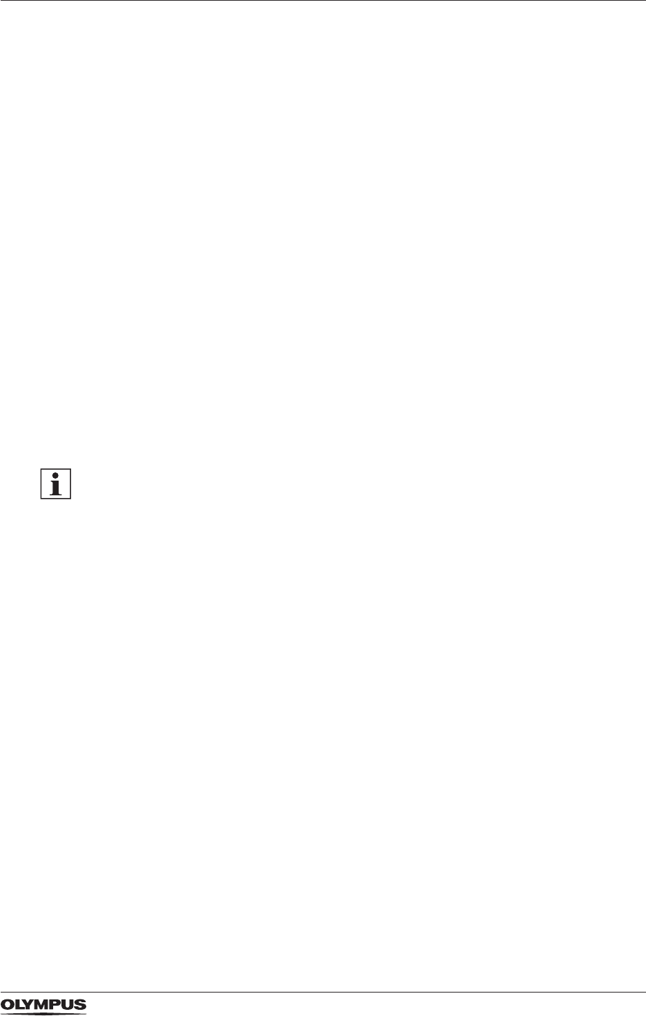
45
System settings
5.5.4 Touch Tone
Use this function to turn on or off the audible feedback when tapping the touch screen. As a
default setting the audible feedback is turned off.
To turn the audible feedback on or off proceed as follows:
1. Tap [MENU] on the All Screen.
The screen [Select Menu] is displayed.
2. Tap [Touch Tone].
- The screen [Touch Tone] is displayed.
- The current setting is highlighted.
3. Tap [On] or [Off] to turn the touch tone on or off.
The selected choice is highlighted.
4. Tap [OK].
The screen [Select Menu] is displayed.
5.5.5 Autostart Setup
Use this function to set a time delay for the feature Autostart. With a time delay the
electrosurgical generator does not activate immediately when the HF instrument touches the
tissue but waits until the specied time has expired.
The time delay is specied in seconds. It is possible to enter a value between 0.0 and 9.9
seconds. The default setting is 1.0 s.
- The Autostart feature is available only for the bipolar coagulation mode SoftCoag.
- Precondition: The Autostart feature is assigned to the BIPOLAR output socket. Refer to
section “Foot switch assignment and Autostart” on page 41.
To set the time delay for the Autostart feature proceed as follows:
1. Tap [MENU] on the All Screen.
The screen [Select Menu] is displayed.
2. Tap the arrow button [Next] to browse to the next page of the screen [Select Menu].
3. Tap [Autostart Setup].
- The screen [Autostart Setup] is displayed.
- The current time delay is displayed in seconds.
4. Tap [+] or [−] to modify the current setting.
5. Tap [OK] to save the current setting.
The screen [Select Menu] is displayed.
5.5.6 Software Version
This function displays the currently installed software version of the electrosurgical
generator.
To display the software version proceed as follows:
1. Tap [MENU] on the All Screen.
The screen [Select Menu] is displayed.
2. Tap the arrow button [Next] to browse to the next page of the screen [Select Menu].
3. Tap [Software Version].
The currently installed software version is displayed.
4. Tap [OK] to return to the screen [Select Menu].
DRAFT – 2017-01-17

46
System settings
5.5.7 Safety Test
This function is required for the annual safety check. Refer to the chapter “Maintenance,
repair and shipment” on page 86. This function is used to close the output relays which
disables the electrosurgical generator for normal operation. Closed output relays are needed
to perform measurements.
- The default setting is [Relays Off]:
The relays are open and the electrosurgical generator is enabled for normal operation.
- The setting [Relays On]:
The relays are closed. The electrosurgical generator is disabled for normal operation.
As soon as the user exits this menu function, the relay setting is automatically set to default,
i.e. normal operation of the electrosurgical generator.
To open or close the output relays proceed as follows:
1. Tap [MENU] on the All Screen.
The screen [Select Menu] is displayed.
2. Tap the arrow button [Next] to browse to the next page of the screen [Select Menu].
3. Tap [Safety Test].
- The screen [Safety Test] is displayed.
- The current setting is highlighted.
4. Tap [Relays On] or [Relays Off].
The new setting is highlighted.
5. Tap [Cancel] to return to the screen [Select Menu].
5.5.8 Bipolar Cut Setup
The electrosurgical generator provides the options to switch the bipolar cutting modes on or
off. If the bipolar cutting modes are switched on, the BIPOLAR pane is divided into a yellow
button for cutting and a blue button for coagulation. The user can access and activate all
bipolar cutting modes.
As a default setting the cutting modes for the BIPOLAR socket are switched off, i.e. only the
blue coagulation button is displayed in the BIPOLAR pane. It is impossible to access and
activate any bipolar cutting mode.
To switch the bipolar cutting modes on or off proceed as follows:
1. Tap [MENU] on the All Screen.
The screen [Select Menu] is displayed.
2. Tap the arrow button [Next] to browse to the next page of the screen [Select Menu].
3. Tap [Bipolar Cut Setup].
- The screen [Bipolar Cut Setup] is displayed.
- The current setting is highlighted.
4. Tap [On] or [Off].
The new setting is highlighted.
5. Tap [OK] to return to the screen [Select Menu].
5.5.9 Service
This function is not intended for customer use. It is password protected and only accessible
for authorized service centers.
DRAFT – 2017-01-17
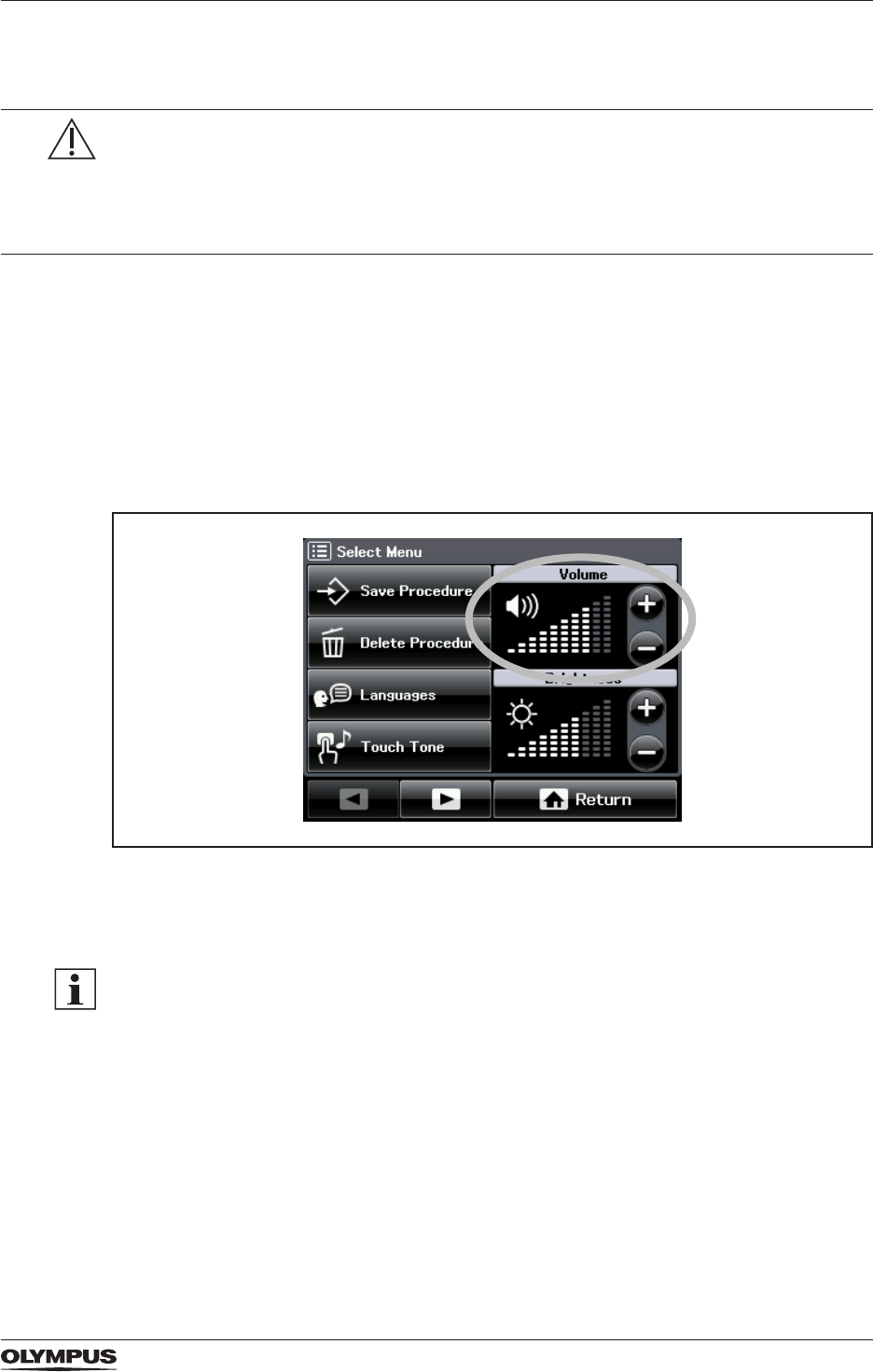
47
System settings
5.5.10 Volume control
WARNING
The output tones play an important role to notice the output power when the electrosurgical
generator is activated. If the output tones are inaudible, then activation may not be
recognized by the user. This could result in injury to the patient.
• Make sure that the output tones are at an audible volume level.
• Adjust the volume level of the output tones to the ambient noises.
The volume of the output tone can be adjusted either with the volume control on the rear
panel of the electrosurgical generator or via touch screen. However, during activation, it is
impossible to enter the screen [Select Menu]. Therefore, the volume needs to be adjusted
with the volume control at the rear panel during activation.
The volume settings range from 1 to 10. The default setting is 7.
To set the volume for the output tone via the touch screen proceed as follows:
1. Tap [MENU] on the All Screen.
The screen [Select Menu] is displayed.
Figure 5.7 Volume control
2. In the volume pane tap [+] to increase the volume. Tap [−] to decrease the volume of the
output tone.
Volume of error tones
The volume of the error tones (low, medium and high priority errors) are not adjustable.
Refer to the chapter “Troubleshooting” on page 78 and to the sections “Alarm system” on
page 97 and “Output tone information” on page 98in the Appendix A.
5.5.11 Brightness control
Use this function to control the brightness of the touch screen. The brightness settings range
from 1 to 10. The default setting is 5.
To set the brightness proceed as follows:
1. Tap [MENU] on the All Screen.
The screen [Select Menu] is displayed.
DRAFT – 2017-01-17
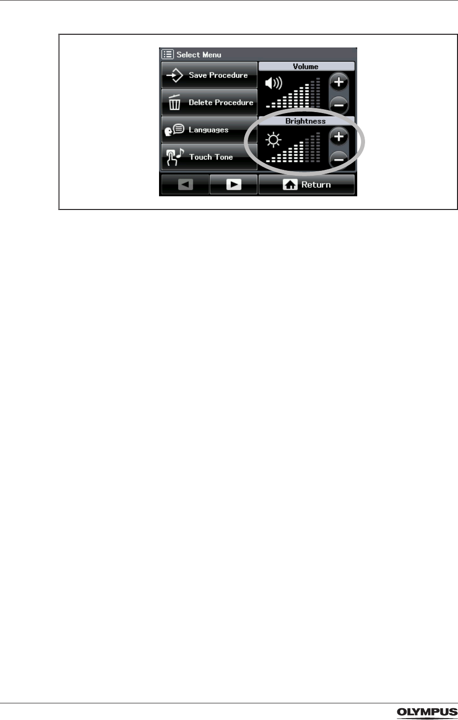
48
System settings
Figure 5.8 Brightness control
2. In the brightness pane tap [+] to increase the brightness. Tap [−] to decrease the
brightness of the touch screen.
DRAFT – 2017-01-17
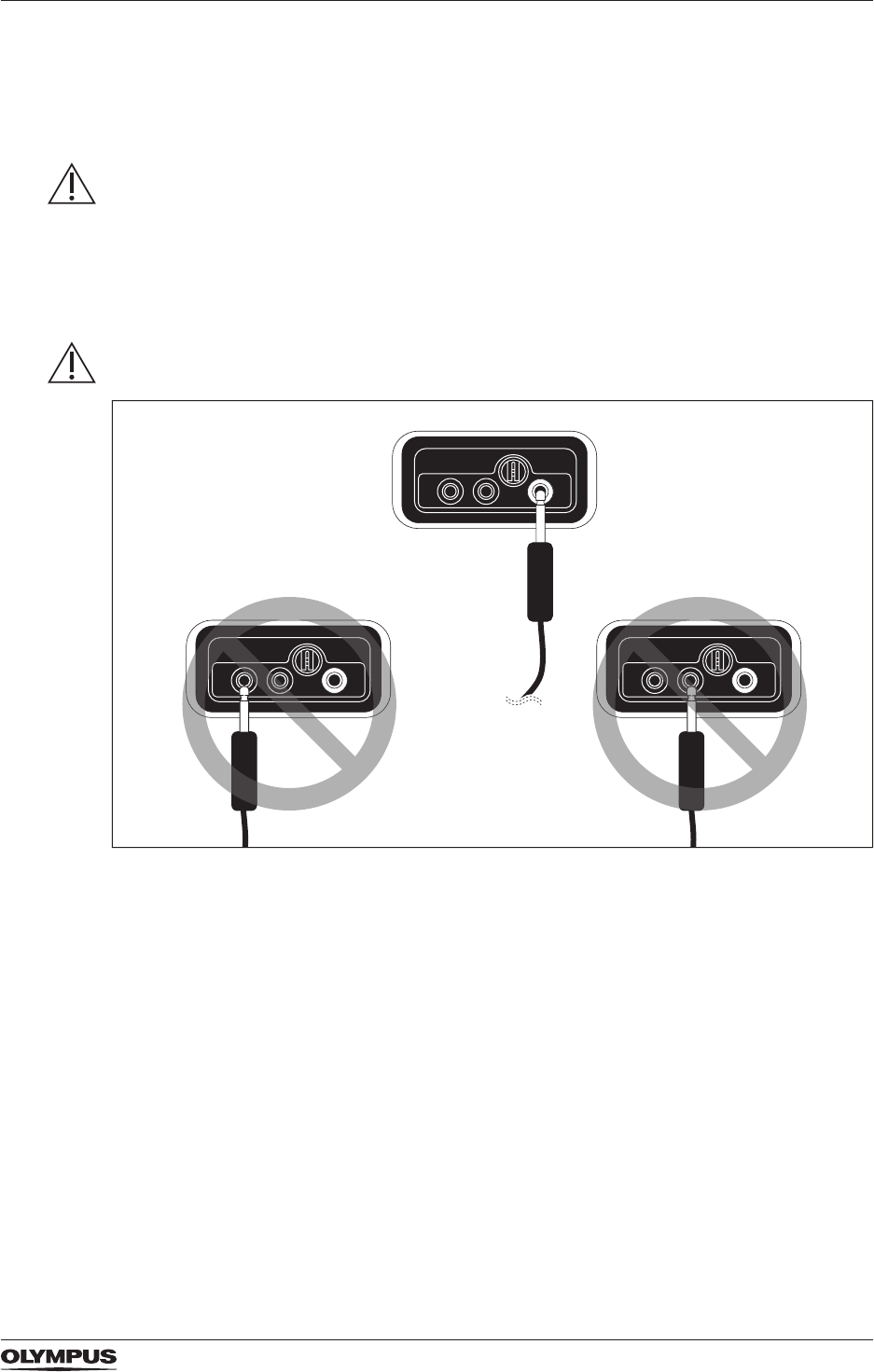
49
Connecting HF instruments
6 Connecting HF instruments
6.1 Safety information for connecting HF instruments
WARNING
Proper connection of the plug
If the HF instrument's plug is not connected properly, then the energy output may not be
suf cient. There is the risk that the HF instrument cuts tissue mechanically. This could result
in bleeding and perforation of the tissue.
• Properly connect the plug of the HF instrument to the corresponding output socket of the
electrosurgical generator as described in the following sections.
CAUTION
Correct connection of a monopolar 1-pin plug with 4 mm pin diameter
Figure 6.1 CAUTION - Correct connection of a monopolar 1-pin plug with a 4 mm
pin diameter
If a 1-pin plug with a pin diameter of 4 mm is connected to any other receptacle than the
right-hand receptacle of the MONOPOLAR output socket, then the output socket may be
destroyed during activation.
• Connect a 1-pin plug with a 4 mm pin diameter only the right-hand receptacle as shown in
the gure above.
DRAFT – 2017-01-17
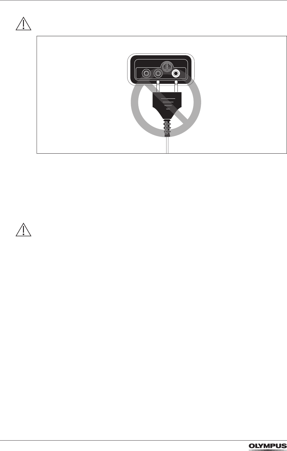
50
Connecting HF instruments
CAUTION
No connection of a 2-pin plug with 4 mm pin diameters
Figure 6.2 CAUTION - Do not connect a 2-pin plug with 4 mm pin diameters to the
MONOPOLAR socket
Connecting a 2-pin plug with pin diameters of 4 mm, e.g. hand switch activated monopolar
forceps, to the MONOPOLAR output socket can damage the electrosurgical generator.
• Do not connect monopolar HF instruments with 2-pin plugs.
• Only connect plugs to the MONOPOLAR output socket as speci ed in the section
"Description of the output sockets" on page 50.
CAUTION
No connection of plugs with single connecting pins
If bipolar HF instruments are used, that have single plugs for each connecting pin, then
there is the risk that the single plugs are connected accidentally to the wrong receptacles.
This could result in damage of the electrosurgical generator.
• Only use bipolar HF instruments that have plugs as described in the section “BIPOLAR
output socket speci cations (applied part)” on page 51.
6.2 Description of the output sockets
Monopolar and bipolar instruments
The electrosurgical generator can be used with monopolar cutting and coagulation
instruments as well as with bipolar cutting and coagulation instruments. The HF instruments
must have an appropriate plug to connect either into the MONOPOLAR socket or the
BIPOLAR socket, see socket descriptions below.
Maximum output voltage
When connecting HF instruments avoid generator settings, e.g. mode, effect, where the
maximum output voltage exceeds the allowed peak voltage of the HF instrument. Refer to
the sections about mode and output characteristics in the “Appendix A” on page 97. Also
refer to the instructions for use of the HF instrument.
DRAFT – 2017-01-17
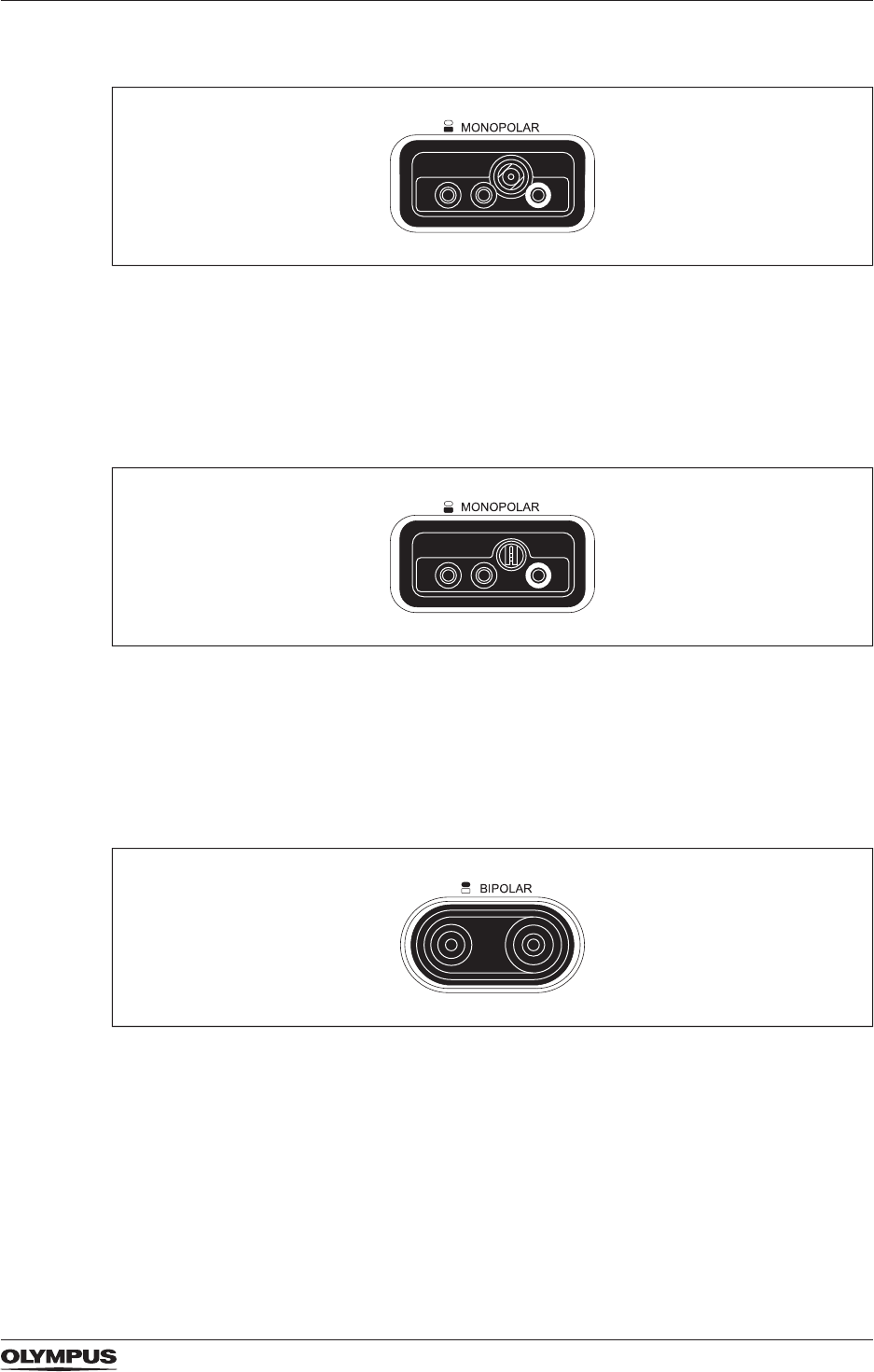
51
Connecting HF instruments
MONOPOLAR output socket for WA90001A (applied part)
Figure 6.3 MONOPOLAR output socket specications for WA90001A
This MONOPOLAR output socket is suitable for the following monopolar plugs:
- 3-pin plug with 4 mm pin diameter (international /Valleylab standard)
- Coaxial plug with 9/5 mm pin diameter (Erbe standard)
- 1-pin plug with 4 mm pin diameter
MONOPOLAR output socket for WA90002A (applied part)
Figure 6.4 MONOPOLAR output socket specications for WA90002A
This MONOPOLAR output socket is suitable for the following monopolar plugs:
- 3-pin plug with 4 mm pin diameter (international/Valleylab standard)
- 1-pin plug with 8 mm pin diameter (Bovie standard)
- 1-pin plug with 4 mm pin diameter
BIPOLAR output socket specications (applied part)
Figure 6.5 Bipolar output socket specications
The BIPOLAR output socket is suitable for the following bipolar plugs:
- 2-pin plug with 4 mm pin diameter, xed pin spacing 28.6 mm (international /Valleylab
standard)
- Coaxial plug with 8/4 mm pin diameter (Erbe standard)
6.3 Connecting
To connect an HF instrument to the electrosurgical generator proceed as follows:
DRAFT – 2017-01-17

52
Connecting HF instruments
1. Refer to the instructions for use of the HF instrument.
2. Inspect the HF instrument, its connection cable and plug for scratches, cracks, and other
damages.
Do not use the HF instrument if any kind of damage is observed.
3. Properly insert the plug of the HF instrument into the corresponding output socket on the
front panel of the electrosurgical generator.
DRAFT – 2017-01-17
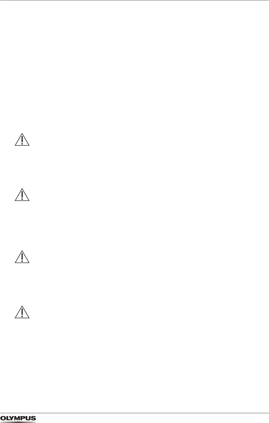
53
Neutral electrode operation
7 Neutral electrode operation
Only for monopolar treatments
Only for monopolar treatments neutral electrodes are required to return the HF current from
the active electrode of the HF instrument back to the electrosurgical generator. In bipolar
electrosurgery both electrodes, the active and the return electrode, are implemented within
the HF instrument.
7.1 Safety information for neutral electrode operation
Improper connection between the neutral electrode and the patient’s skin surface may cause
burns.
• When attaching a neutral electrode, consider the safety notes as described below.
• For further details on neutral electrodes, refer to the specic instructions for use of the
neutral electrode.
DANGER
Neutral electrodes for infants
If the output power of the electrosurgical generator exceeds the permissible power of a
neutral electrode for infants (patient weight 0...15 kg), then this will result in severe burns to
the patient.
• Only use output settings within the permissible range of output power for the neutral
electrode. Refer to the instructions for use of the neutral electrode.
WARNING
Size of neutral electrodes
If the size of the neutral electrode is too small for the patient, then this could result in burns
to the patient.
• Choose the largest possible neutral electrode that is adequate for the patient.
• Consider the size of the neutral electrode particularly for obese patients.
• Consider the size of the neutral electrode particularly if high output power levels are
needed.
WARNING
Non-split type neutral electrodes
If non-split type neutral electrodes are used, then the contact quality monitor does not work.
In case that the non-split type neutral electrode detaches from the patient, then no warning
signal sounds. This could result in burns to the patient.
• Only use split type neutral electrodes. Refer to the section “Compatible neutral electrodes”
on page 89.
WARNING
Mechanical tissue cutting
If the HF instrument is at the treatment site when a neutral electrode failure is indicated, then
tissue might be cut mechanically with the HF instrument. This could result in bleeding and
perforation.
• Note that the output of energy automatically stops when the CQM indicates a neutral
electrode failure.
DRAFT – 2017-01-17
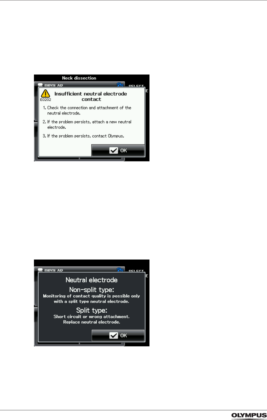
54
Neutral electrode operation
7.2 Split type and non-split type neutral electrodes and CQM
Contact quality monitoring (CQM) for split type neutral electrodes
If a split type neutral electrode is connected to the electrosurgical generator, it is possible
to detect unintended detachment of the neutral electrode from the patient. If the contact
between the neutral electrode and the patient’s skin is insufcient, the split type CQM
indicator shines red. Furthermore, an alarm tone sounds and the following error message is
displayed on the touch screen:
Figure 7.1 Error message E0202 “Insufcient neutral electrode contact”
In this case, the activation of the electrosurgical generator is stopped automatically. The
neutral electrode must be reattached or a new one must be used. The split type CQM
indicator will only shine green while the contact between the neutral electrode and the skin
of the patient is within an acceptable resistance range, see section “Specications for the
CELON ELITE ESG-200” on page 90.
No contact quality monitoring for non-split type neutral electrodes
If a non-split type neutral electrode is connected to the electrosurgical generator, it is
impossible to detect any detachment of the neutral electrode from the patient. When
connecting a non-split type neutral electrode, the following message box is displayed on the
touch screen:
Figure 7.2 Message box “Neutral electrode”
To avoid unintended use of a non-split type neutral electrode the displayed message must
be conrmed by the user.
DRAFT – 2017-01-17
55
Neutral electrode operation
The CQM indicator for non-split type neutral electrodes shines green if a non-split type
neutral electrode is detected.
7.3 Meaning of CQM indicator condition
The CQM indicator can take on the following conditions:
Indicator for split type neutral electrodes shines green
- CQM detects a split type neutral electrode.
- Sufcient contact between the neutral electrode and the patient’s skin.
- Activation is possible.
• Continue with the procedure.
Indicator for split type neutral electrodes shines red
During activation: During standby:
1) Insufcient contact between the
neutral electrode and the patient’s skin.
2) The connection between the neutral
electrode and the electrosurgical
generator is interrupted.
- Activation stops automatically.
- An alarm tone sounds and the error
message E0202 “Insufcent neutral
electrode contact” is displayed.
• Follow the instructions given in the
error message.
1) No neutral electrode connected.
2) Insufcient contact between the
neutral electrode and the patient’s skin.
- Activation is disabled.
Indicator for non-split type neutral electrodes shines green
If a split type neutral electrode is
connected:
If a non-split type neutral electrode is
connected:
1) CQM cannot detect the split type
neutral electrode.
2) The split type neutral electrode has a
short circuit.
- The message box “Neutral electrode”
(Figure 7.2) is displayed.
• Tap [OK] to conrm the message.
• Replace the split type neutral
electrode.
1) CQM detects a non-split type neutral
electrode.
- Activation is possible.
• Continue with the procedure.
7.4 Correct usage of neutral electrodes
For the safe use of neutral electrodes refer to the instructions for use of the correspondent
neutral electrode and take account of the following:
Compatible neutral electrodes
The section “Compatible neutral electrodes” on page 89 lists different neutral electrodes
that are compatible for the use with the electrosurgical generator.
DRAFT – 2017-01-17

56
Neutral electrode operation
• Only use compatible neutral electrodes as listed in the section “Compatible neutral
electrodes” on page 89.
• Only use self-adhesive neutral electrodes to prevent compression necrosis.
• Do not use capacitive coupling neutral electrodes.
Immaculate neutral electrodes
• Check the use by date of the neutral electrode. Only use neutral electrodes with an
unexpired use by date.
• Check the packaging of the neutral electrode. Only use neutral electrodes with an
immaculate packaging.
• Check the neutral electrode for damages, modications and sharp edges. Only use
immaculate neutral electrodes.
Safe attachment
• Do not fold or wrinkle the neutral electrode. Only attach neutral electrodes that have a
smooth surface.
• Make sure that the site to which the neutral electrode is attached is clean, dry and free
from hair.
• Make sure that the entire surface of the neutral electrode is in direct contact with the
patient's skin.
• Do not attach the neutral electrode in the vicinity of a metal implant.
• Do not place the neutral electrode over bony prominences or on scar tissue.
• Apply the long edge of the neutral electrode to face the surgical site.
• If the patient is repositioned during surgery, conrm proper contact between the neutral
electrode and the patient's skin as well as the integrity of cable and clamp connections
before continuing.
• Do not reposition or relocate a the neutral electrode after initial application.
Removing
• When removing, start at the corner and gently peel of the neutral electrode from the
patient's skin.
7.5 Connecting to the electrosurgical generator
Neutral electrode socket specications
The neutral electrode socket at the electrosurgical generator is suitable for the following
plugs:
- Plugs with 2 sockets
- 2.5 mm socket diameter
- Socket spacing: 10 mm
7.5.1 Connecting a neutral electrode with a pre-attached cable
• To connect a neutral electrode with a pre-attached cable refer to the instructions for use of
the neutral electrode.
DRAFT – 2017-01-17
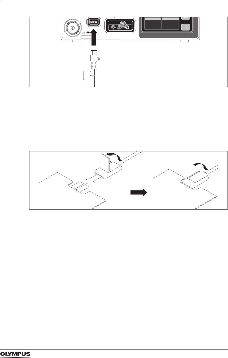
57
Neutral electrode operation
Figure 7.3 Connecting the plug of the neutral electrode
• Insert the plug of the neutral electrode into the neutral electrode socket on the front panel
of the electrosurgical generator.
7.5.2 Connecting a neutral electrode without a pre-attached cable
To connect a neutral electrode without a pre-attached cable proceed as follows:
• Refer to the instructions for use of the connecting cable and of the neutral electrode.
Figure 7.4 Fixing the neural electrode to the connecting cable
1. Lift the locking lever of the connecting cable.
2. Position the tab of the neutral electrode evenly between the clamp jaws of the
connecting cable.
3. Completely push down the locking lever to lock the clamp.
4. Insert the plug of the connecting cable into the neutral electrode socket on the front
panel of the electrosurgical generator.
MENU
DRAFT – 2017-01-17
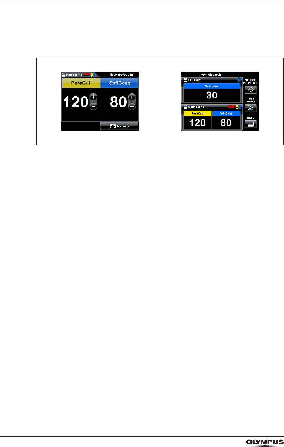
58
Neutral electrode operation
7.6 Verifying the contact quality monitor indicator
If the indicator shines green although there is no neutral electrode attached, there is a
malfunction of the electrosurgical generator. In this case, do not use this electrosurgical
generator.
Figure 7.5 Split type indicator for CQM shining red on the Set Screen and on the
All Screen
• After attaching a neutral electrode to the patient, check the CQM indicator:
When using a split type neutral electrode
The split type indicator must shine green. Refer to the section “Split type and non-split type
neutral electrodes and CQM” on page 54.
When using a non-split type neutral electrode
The non-split type indicator must shine green. Refer to the section “Split type and non-split
type neutral electrodes and CQM” on page 54.
DRAFT – 2017-01-17
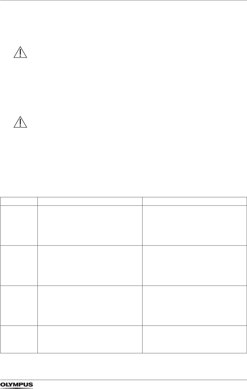
59
Output settings
8 Output settings
8.1 Safety information on output settings
WARNING
Strong RFITT+RCAP
When using the mode Strong RFITT+RCAP, the output of energy is stopped if the HF
electrode is withdrawn from the patient or if the tissue is totally desiccated after a long
treatment time. There is the risk that too much tissue is coagulated which can result in injury
to the patient.
• Make sure to stop the output power on the basis of the applied amount of energy, the
duration of activation and the progress of coagulation.
• Refer to the explanations on the Strong RFITT+RCAP mode in the section “The bipolar
RFITT coagulation modes” on page 63.
CAUTION
Conscious patients and muscle stimulation
All cutting modes are supported by High Power Cut Support (HPCS). HPCS generates high
current densities which result in nerve and muscle stimulation. This can cause pain and
discomfort to patients without sedation, pain medication or general anesthesia.
• Use output modes without HPCS for conscious patients. Refer to the section “Overview of
output modes” on page 59.
8.2 Overview of output modes
8.2.1 Monopolar modes
Mode name Application/HF instrument Specic technical features
FineCut - Cutting of varying tissue structures.
- Monopolar cutting electrodes, e.g.
needle electrodes.
- Low spark intensity for small thermal
effect.
- High Power Cut Support (HPCS).
- Fast Spark Monitor (FSM) ensures
smooth and reproducible cutting in
varying tissue, e.g. muscle and fat.
PureCut - Cutting of varying tissue structures.
- Monopolar cutting electrodes, e.g.
needle electrodes.
- Medium spark intensity for medium
thermal effect.
- High Power Cut Support (HPCS).
- Fast Spark Monitor (FSM) ensures
smooth and reproducible cutting in
varying tissue, e.g. muscle and fat.
StrongCut - Cutting of varying tissue structures.
- Monopolar cutting electrodes, e.g.
needle electrodes.
- High spark intensity for big thermal
effect.
- High Power Cut Support (HPCS).
- Fast Spark Monitor (FSM) ensures
smooth and reproducible cutting in
varying tissue, e.g. muscle and fat.
PulseCut - Intermittent cutting, e.g. for endoscopic
operations.
- Monopolar cutting electrodes, e.g.
needle electrodes, snare electrodes.
- High Power Cut Support (HPCS).
- Fast Spark Monitor (FSM) ensures
smooth and reproducible cutting in
varying tissue, e.g. muscle and fat.
DRAFT – 2017-01-17

60
Output settings
Mode name Application/HF instrument Specic technical features
SoftCoag - Coagulation of tissue with little sticking
and carbonization.
- Monopolar coagulation electrodes, e.g.
coagulation forceps, ball electrodes.
- Little carbonization and adhesion.
ForcedCoag - Fast and effective coagulation.
- Monopolar coagulation electrodes, e.g.
coagulation forceps, ball electrodes.
- Spark allows coagulation also with
relatively small electrodes.
Table: Overview of monopolar cut and coagulation modes
8.2.2 Bipolar modes
Mode name Application/HF instrument Specic technical features
FineCut - Cutting of tissue.
- Bipolar cutting electrodes, e.g. needle
electrodes.
- Low spark intensity for small thermal
effect.
- High Power Cut Support (HPCS).
PureCut - Cutting of tissue.
- Bipolar cutting electrodes, e.g. needle
electrodes.
- Medium spark intensity for medium
thermal effect.
- High Power Cut Support (HPCS).
StrongCut - Cutting of tissue.
- Bipolar cutting electrodes, e.g. needle
electrodes.
- High spark intensity for big thermal
effect.
- High Power Cut Support (HPCS).
SoftCoag - Coagulation of tissue.
- Bipolar coagulation electrodes, e.g.
coagulation forceps.
- Little carbonization and adhesion.
- Autostart selectable.
Fine RFITT - Controlled tissue coagulation,
radiofrequency ablation.
- Dedicated bipolar coagulation
electrodes, e.g. RFITT electrodes.
- Automatic end-of-procedure detection.
- Audible feedback.
Pure RFITT - Controlled tissue coagulation,
radiofrequency ablation.
- Dedicated bipolar coagulation
electrodes, e.g. RFITT electrodes.
- Automatic end-of-procedure detection.
- Audible feedback.
Strong RFITT - Controlled deep tissue coagulation,
radiofrequency ablation.
- Dedicated bipolar coagulation
electrodes, e.g. cooled RFITT
electrodes.
- Automatic end-of-procedure detection.
- Audible feedback.
Strong
RFITT+RCAP
- Controlled deep tissue coagulation,
radiofrequency ablation.
- Dedicated bipolar coagulation
electrodes, e.g. cooled RFITT
electrodes.
- Resistance Controlled Automatic Power
(RCAP) to avoid premature tissue
desiccation.
- Automatic deactivation when the tissue
resistance exceeds a limit value.
Table: Overview of bipolar cut and coagulation modes
DRAFT – 2017-01-17
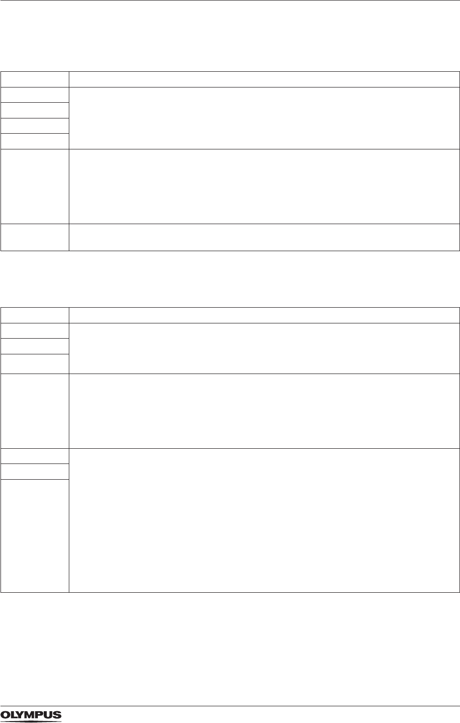
61
Output settings
8.3 Tissue effects depending on the output power level
8.3.1 Monopolar modes
Mode name Effect on tissue
FineCut - Increasing the output power level results in an increased thermal effect and an
increased cutting capability.
- Decreasing the output power level results in a decreased thermal effect and a
decreased cutting capability.
PureCut
StrongCut
PulseCut
SoftCoag - Increasing the output power level results in an increased coagulation depth for short
time applications.
- Decreasing the output power level results in a decreased coagulation depth for short
time applications.
- Nevertheless, to achieve the full potential coagulation depth, a long application time
with a low power setting is necessary.
ForcedCoag - Increasing the output power level results in an increased thermal effect.
- Decreasing the output power level results in a decreased thermal effect.
Table: Tissue effects depending on output power level in monopolar modes
8.3.2 Bipolar modes
Mode name Effect on tissue
FineCut - Increasing the output power level results in an increased thermal effect and an
increased cutting capability.
- Decreasing the output power level results in a decreased thermal effect and a
decreased cutting capability.
PureCut
StrongCut
SoftCoag - Increasing the output power level results in an increased coagulation depth for short
time applications.
- Decreasing the output power level results in a decreased coagulation depth for short
time applications.
- Nevertheless, to achieve the full potential coagulation depth, a long application time
with a low power setting is necessary.
Fine RFITT For short time applications that end signicantly earlier than the automatic end-
of-procedure detection:
- Increasing the output power level results in an increased coagulation depth.
- Decreasing the output power level results in a decreased coagulation depth.
For application times until automatic end-of-procedure detection:
- Increasing the output power level results in faster coagulation, a quicker end of
procedure and a decreased coagulation depth.
- Decreasing the output power level results in slower coagulation, a later end of
procedure and an increased coagulation depth.
• Refer to the section “The bipolar RFITT coagulation modes” on page 63.
Pure RFITT
Strong RFITT
DRAFT – 2017-01-17
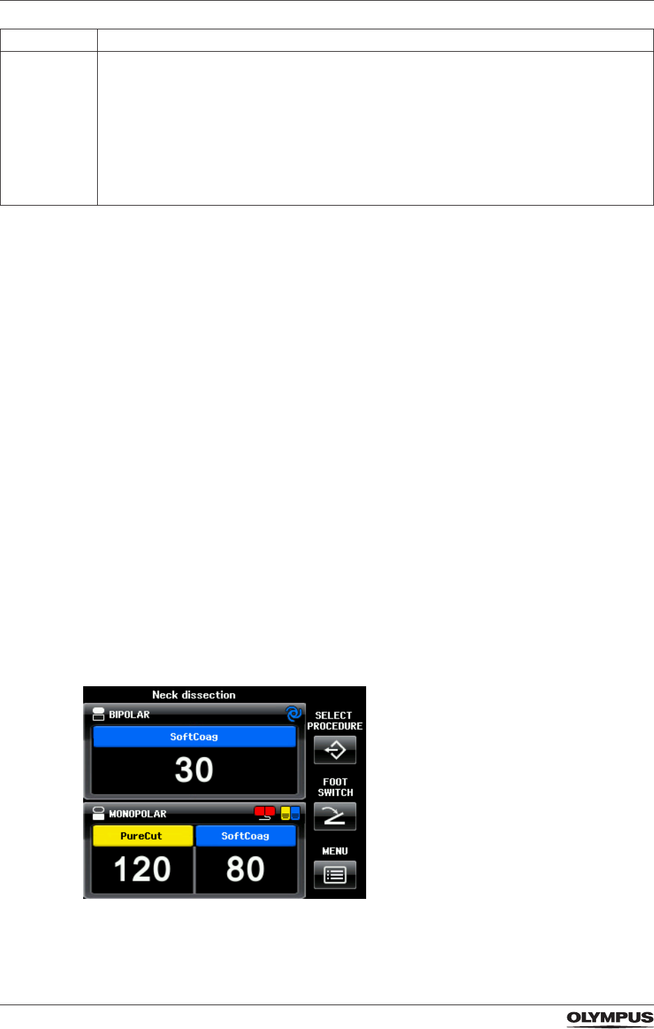
62
Output settings
Mode name Effect on tissue
Strong RFITT
+RCAP
If the output power level is below the optimum power level:
- Increasing the output power level results in an increased coagulation depth.
- Decreasing the output power level results in a decreased coagulation depth.
If the output power level is above the optimum power level:
- Increasing and decreasing the output power level does not result in a signicant
change of coagulation depth because of RCAP.
• Refer to the section “The bipolar RFITT coagulation modes” on page 63.
Table: Tissue effects depending on output power level in bipolar modes
8.4 Selecting the appropriate output settings
Appropriate selections
• Select a mode according to the type of procedure that will be performed and according to
the HF instruments that will be used.
• For details on the applications, HF instruments and specic technical features of the
different modes and for the impact of output power levels refer to the section “Overview of
output modes” on page 59.
Output power level and applied power
The output power levels that are displayed on the All Screen or on the Set Screen represent
the maximum possible output power levels in watts. The actually applied power depends on
the tissue characteristics, e.g. resistance.
Minimum output power level
If the output power level of a mode is set below the minimum allowed value by the user, then
the electrosurgical generator automatically sets the output power level to 0. Instead of a
number for the output power level, [--] is displayed. Each mode has specic minimum output
power levels. Refer to the section “Mode characteristics according to IEC 60601-2-2” on
page 101 in the Appendix B. It is impossible to change the mode or the output power level
during activation.
Selecting the settings on the touch screen
To set the required output settings proceed as follows:
Figure 8.6 All Screen
DRAFT – 2017-01-17
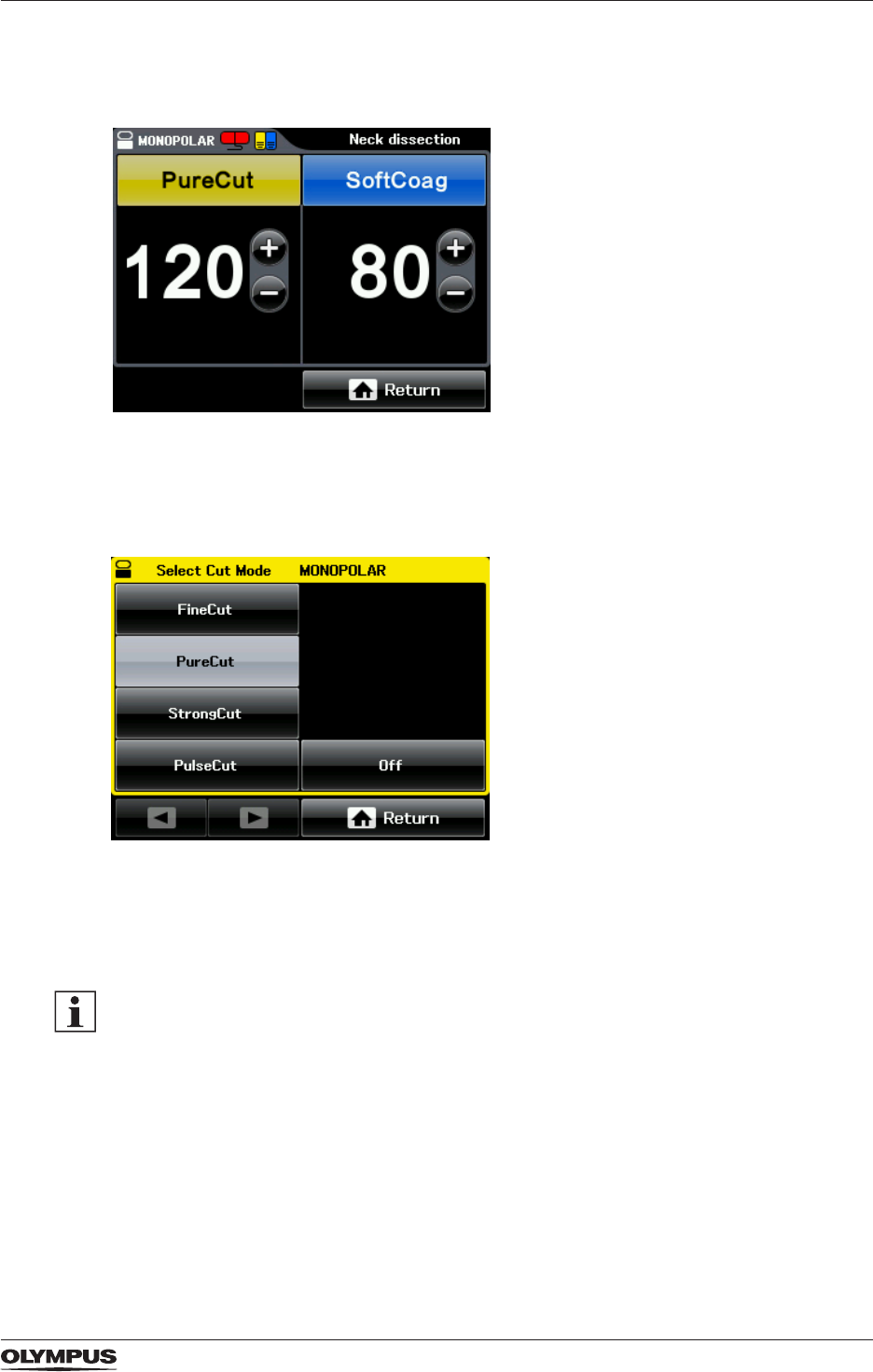
63
Output settings
1. On the All Screen tap into the pane for the required output socket, i.e. either
[MONOPOLAR] or [BIPOLAR].
The Set Screen is displayed.
Figure 8.7 Set Screen for monopolar modes
2. Tap the yellow button for selecting a cutting mode or tap the blue button for selecting a
coagulation mode.
The Mode Screen is displayed. The currently selected mode is highlighted.
Figure 8.8 Mode Screen for monopolar cutting modes
3. Tap the button of the required mode, e.g. [FineCut].
The display changes back to the Set Screen and shows the chosen mode.
4. Increase or decrease the output power level by tapping [+] or [−] of the chosen mode.
Tapping [Off] on the Mode Screen completely deactivates cutting or coagulation for this
output socket. Then, instead of a number for the output power level, [--] is displayed.
8.5 The bipolar RFITT coagulation modes
The medical purpose of the radiofrequency induced thermotherapy (RFITT) is to achieve
controlled tissue coagulation. The electrosurgical generator offers 4 different RFITT modes
as mentioned in the table above.
One of these modes also offers Resistance Controlled Automatic Power (RCAP) which is
explained further below.
DRAFT – 2017-01-17
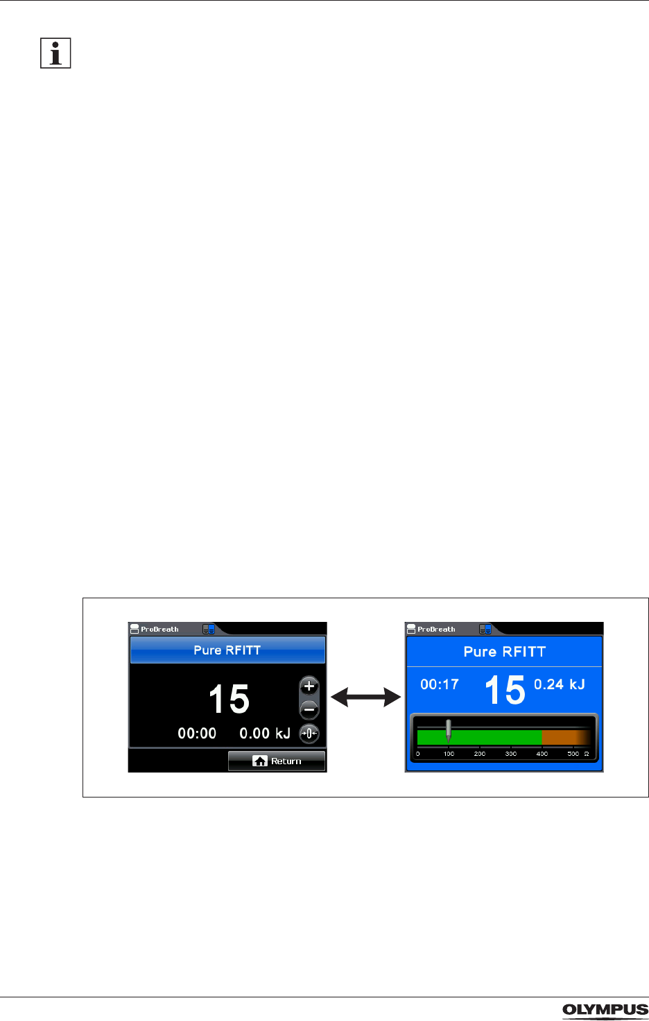
64
Output settings
The RFITT modes are available only for selected CELON bipolar applicators, e.g.
CelonProSleep plus or CelonProBreath.
RFITT modes without RCAP
During activation, the electrosurgical generator provides audible feedback of the coagulation
status. The frequency of the output tone is proportional to the tissue resistance at any
particular moment. As the measured tissue resistance increases, the frequency of the output
tone also increases. This permits audible monitoring of the coagulation status since the
latter is directly connected with the tissue resistance.
Energy is applied until the tissue resistance exceeds a limit value, i.e. automatic end-
of-procedure detection. Then the power output is automatically stopped (for the modes
Fine RFITT, Strong RFITT) or reduced to a minimum (Pure RFITT), because the coagulation
process is completed due to desiccation of the tissue. This is indicated by an intermittent
audible signal.
Detailed information on output limits and output characteristics are given in the “Appendix A”
on page 97.
Strong RFITT+RCAP
The medical purpose of the mode Strong RFITT+RCAP is to achieve deep tissue
coagulation without signicant tissue desiccation.
Once the tissue resistance increases signicantly, which indicates beginning tissue
desiccation, the electrosurgical generator reduces the power automatically. This enables
the tissue to rehydrate, resulting in normal electrical resistance of the tissue after a few
seconds. Detecting this decrease of resistance, the electrosurgical generator automatically
increases the power again to the preset level and continues the heating process. This cycle
is repeated until the user stops the activation or until the tissue resistance exceeds a limit
value. In the latter case, the power output is automatically stopped, which is indicated by an
intermittent audible signal.
Application time and energy counter for RFITT modes
Figure 8.1 Counters on the Set Screen and during activation
On the Set Screens of RFITT modes an application time counter and an energy counter are
displayed. The counters indicate previous treatment parameters. During activation of the
electrosurgical generator these counters are constantly updated.
- The application time counter shows the total application duration of output power in
minutes and seconds in the format [00:00].
After 999 minutes and 59 seconds the application time counter starts counting from 0.
DRAFT – 2017-01-17
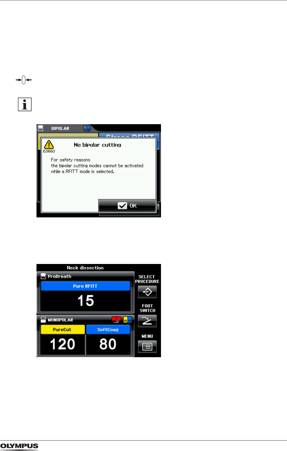
65
Output settings
- The energy counter shows the total amount of energy emitted in kilojoules in the following
formats:
- [0.00 kJ] for up to 9.99 kJ
- [00.0 kJ] for up to 99.9 kJ
- [000 kJ ] for up to 999 kJ
- When exceeding an energy amount of 999 kJ the electrosurgical generator continues to
count in Megajoules (MJ).
• To reset the counters to 0 either switch off the electrosurgical generator or tap [Reset] on
the Set Screen.
To avoid patient injury and damage of bipolar RFITT applicators by unintended activation of
bipolar cutting, no bipolar cutting mode can be activated while a RFITT mode is selected. If
the yellow cut pedal is pressed by mistake then the following error message is displayed:
Figure 8.2 Error message E0660 “No bipolar cutting”
8.6 Output settings for selected CELON bipolar applicators
Figure 8.3 Automatic instrument recognition
The electrosurgical generator recognizes the CELON bipolar applicator that is connected.
This means:
- The name of the connected CELON bipolar applicator is displayed in the BIPOLAR pane
of the touch screen, e. g. [ProBreath].
- Only compatible modes and output power settings are available.
DRAFT – 2017-01-17
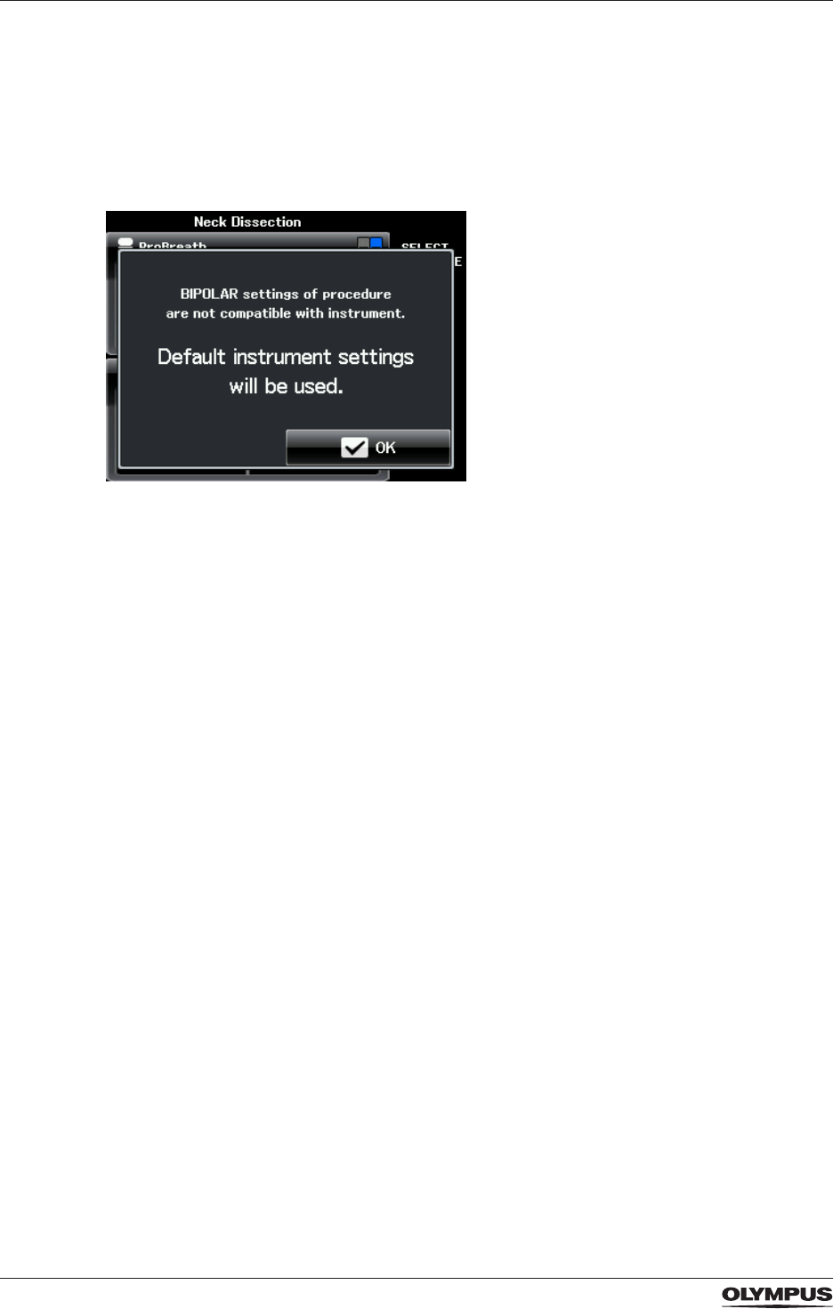
66
Output settings
- The user can select one of these compatible modes and can change the output power
level within a restricted range.
Incompatible settings
If the selected settings are not compatible with the bipolar applicator, the electrosurgical
generator automatically switches to settings that are compatible with the connected bipolar
applicator. The user is informed by a message box, e.g. the following:
Figure 8.4 Incompatible settings
DRAFT – 2017-01-17
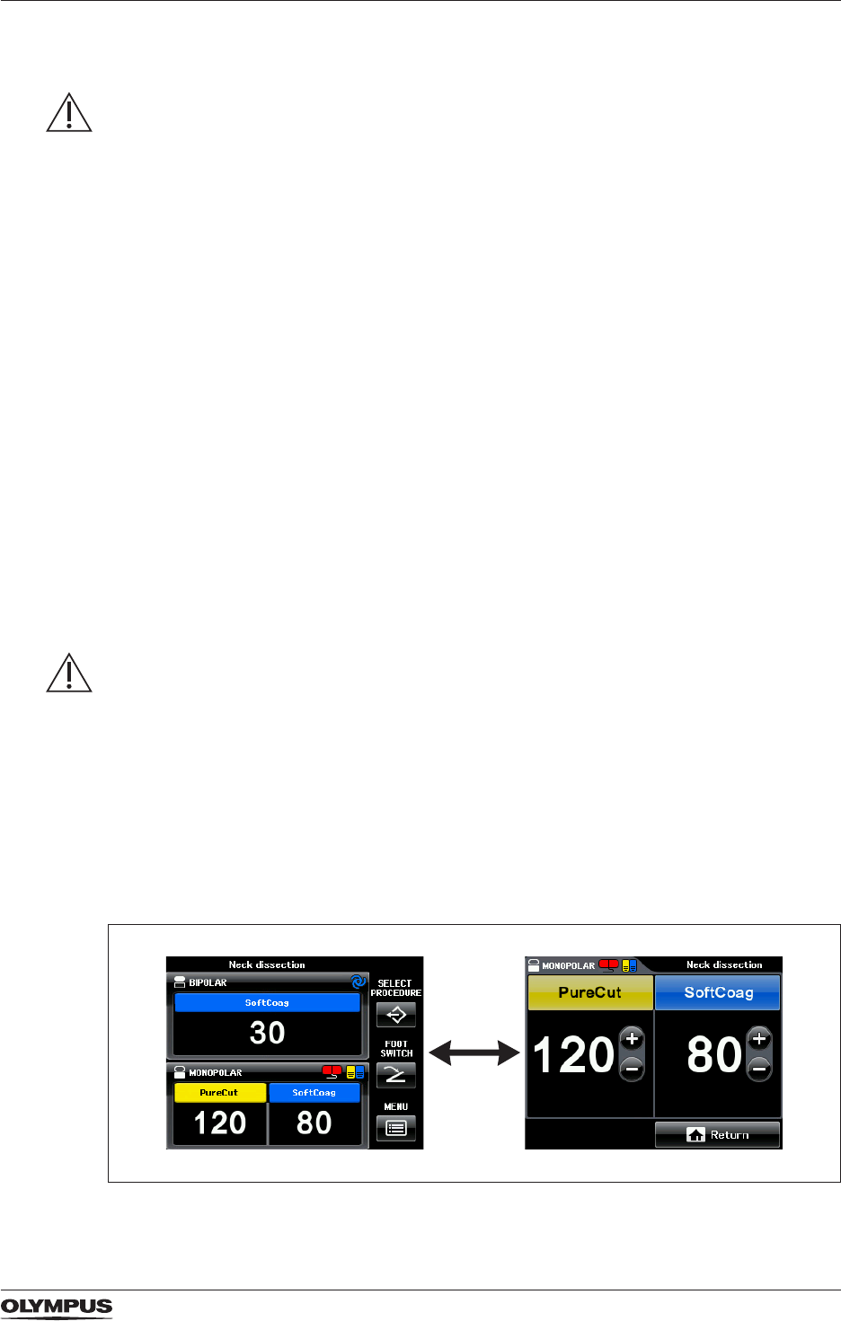
67
Inspection before operation
9 Inspection before operation
WARNING
Irregularities and damage
Any irregularity or damage of the electrosurgical generator and its equipment compromises
the safety and can result in injury to the patient, the user and the medical personnel.
• Prior to every operation, inspect the electrosurgical generator as described in this chapter.
• Prior to every operation, inspect all equipment for irregularity or damage.
• Do not use the electrosurgical generator if any irregularity or damage is suspected.
• Do not use the equipment if any irregularity or damage is suspected.
• Refer to the chapter “Troubleshooting” on page 78.
9.1 Inspecting the supply of power
Power switch and start screen
To test the power connection of the electrosurgical generator proceed as follows:
1. Switch on the electrosurgical generator.
2. Check that the power switch lights up.
3. Check that the touch screen lights up.
The start screen with the Olympus logo is displayed shortly and the start melody is
played.
4. Check that the All Screen is displayed after the start screen.
The All Screen recalls the last settings of all output sockets.
9.2 Inspecting the touch screen
CAUTION
Operation of the touch screen
Wrong operation of the touch screen can cause malfunction or damage to the touch screen.
• Only tap one button or pane at a time.
• Only tap the touch screen from the front. Avoid oblique angles when tapping the touch
screen.
• Do not use pointed objects, e.g. a pen, to tap the touch screen.
• Do not tap the touch screen unintentionally.
• Do not apply excessive loads on the surface of the touch screen.
• Remove dust and dirt by wiping the touch screen with a cloth.
Testing the setting of output power levels
Figure 9.1 Changing from the All Screen to the Set Screen
DRAFT – 2017-01-17
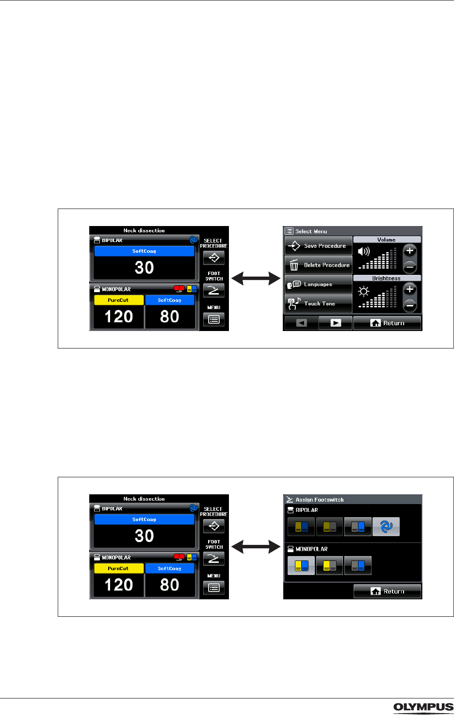
68
Inspection before operation
To test the functionality of the output power settings proceed as follows:
1. Tap into the pane [MONOPOLAR].
Check that the screen changes from the All Screen to the Set Screen, displaying the
settings of the MONOPOLAR output socket.
2. Test the plus buttons by tapping [+].
For values up to 50 the output power level increases in steps of 1 per tap.
For values above 50 the plower level increases in steps of 5 per tap.
3. Test the minus buttons by tapping [−].
For values up to 50 the output power level decreases in steps of 1 per tap.
For values above 50 the plower level decreases in steps of 5 per tap.
4. Touch and hold [+] and then [−] to check that the output power level increases/
decreases fast.
5. Tap [Return] to return to the All Screen.
Testing the screen [Select Menu]
Figure 9.2 Changing from the All Screen to the screen [Select Menu]
To test the functionality of the screen [Select Menu] proceed as follows:
1. Tap [MENU] on the All Screen.
Check that the screen changes from the All Screen to the screen [Select Menu].
2. Tap [Return] to return to the All Screen.
9.3 Inspecting the foot switch assignment
Figure 9.3 Changing from the All Screen to the screen [Assign Foot Switch]
To test the functionality for the foot switch assignment proceed as follows:
1. Tap [FOOT SWITCH] on the All Screen.
DRAFT – 2017-01-17
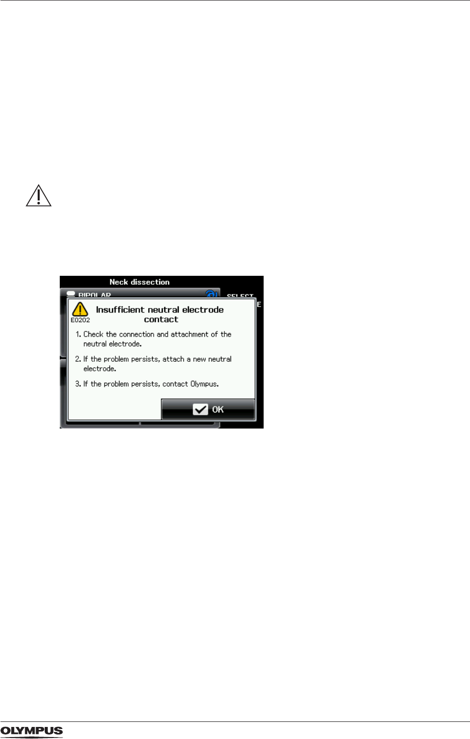
69
Inspection before operation
The screen changes from the All Screen to the screen [Assign Foot Switch].
2. In the MONOPOLAR pane tap the button [double pedal foot switch].
Check that this button is highlighted.
3. Disconnect the foot switch plug from the electrosurgical generator.
Check that no foot switch buttons are highlighted anymore.
4. Tap [Return] to return to the All Screen.
9.4 Inspecting the alarm system
This section describes how to test the functionality of the neutral electrode alarm
substitutionally for the whole alarm system.
WARNING
Alarm function
If the alarm function is not normal, the electrosurgical generator might fail to detect an
equipment error. This may result in unexpected burns, perforation or bleeding.
• Inspect the alarm function before each use.
Neutral electrode warning
Figure 9.4 Error message E0202 “Insufcient neutral electrode contact”
To test the functionality of the neutral electrode alarm proceed as follows:
1. Make sure that no neutral electrode is connected to the electrosurgical generator.
2. Check that the contact quality monitor indicator shines red.
3. Try to activate any monopolar mode by pressing the corresponding foot switch pedal.
• Check that the output power cannot be activated.
• Check that the error message E0202 is displayed and that an alarm tone sounds.
• Check that the alarm tone stops and that the error message E0202 is closed after
approximately 10 seconds.
DRAFT – 2017-01-17
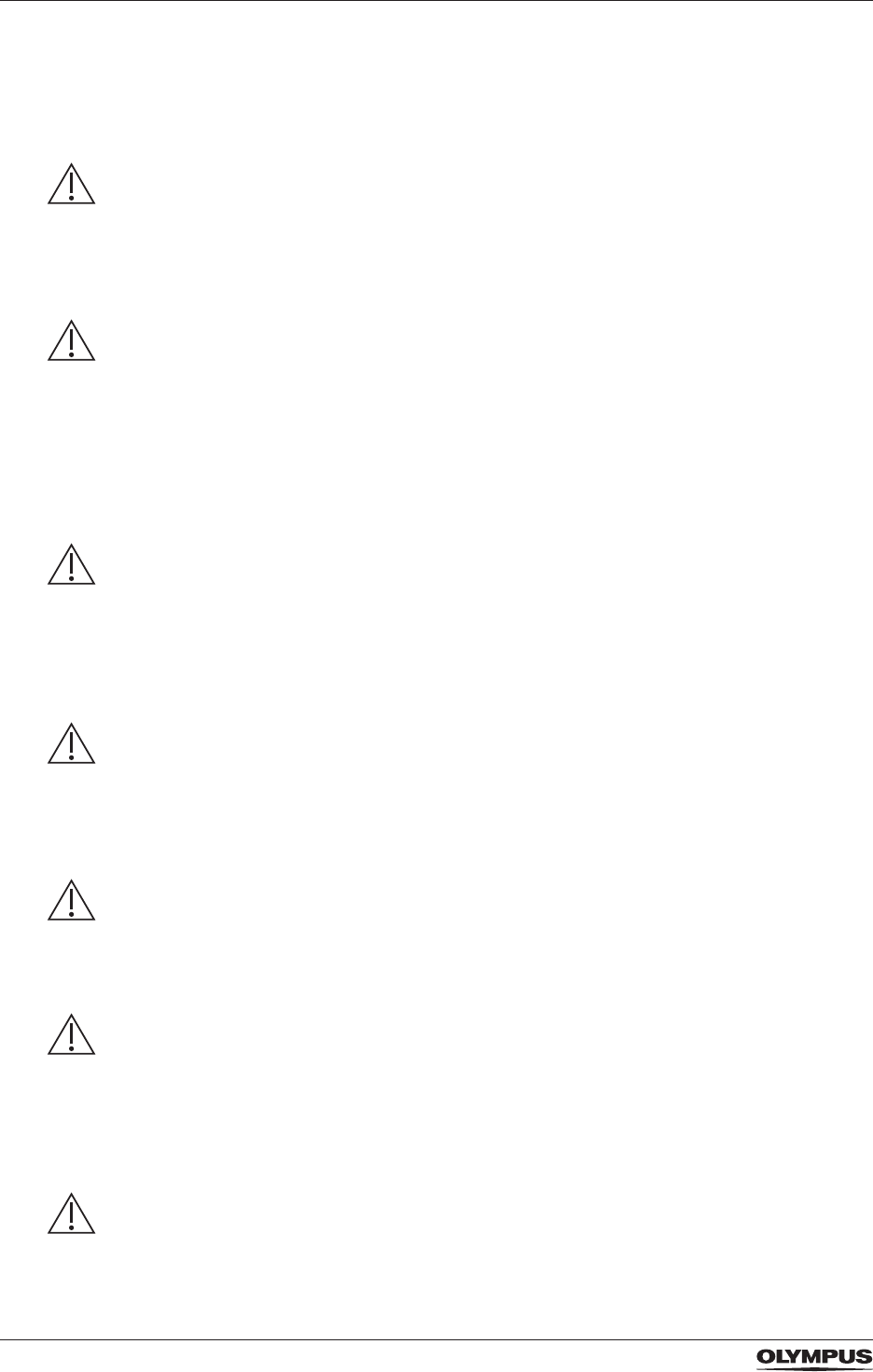
70
Operation
10 Operation
10.1 Safety information for operation
DANGER
Inadequate output of the electrosurgical generator could result in death or serious injury to
the patient.
• Immediately stop the activation of output power as soon as inadequate output is observed.
• If the foot switch or the hand switch of the HF instrument does not react, then use the
power switch as emergency stop.
WARNING
Irregularities and damage
Any irregularity or damage of the electrosurgical generator and its equipment compromises
the safety and can result in injury to the patient, the user and the medical personnel.
• Prior to every operation, inspect the electrosurgical generator as described in this chapter.
• Prior to every operation, inspect all equipment for irregularity or damage.
• Do not use the electrosurgical generator if any irregularity or damage is suspected.
• Do not use the equipment if any irregularity or damage is suspected.
• Refer to the chapter “Troubleshooting” on page 78.
WARNING
Autostart
When using Autostart for the bipolar mode SoftCoag, then unintended tissue contact of the
HF instrument can cause burns to the user and the patient.
• When using Autostart, be aware that the output of power starts as soon as the HF
instrument is in contact with tissue.
• Avoid unintended tissue contact with the HF instrument.
WARNING
Visibility of the activated HF instrument
During endoscopic procedures, loosing sight of the tip of the activated HF instrument can
result in bleeding, perforation and burns to the patient.
• Make sure that the tip of the activated HF instrument is always visible in the endoscopic
image.
WARNING
Metal clips
If the tip of the activated HF instrument is in close to a metal clip or another metallic object
within the patient, then the tissue around this metallic object could be burned.
• Make sure that the activated HF instrument does not get close to metallic objects.
WARNING
Accidental activation
Accidentally activating the output of the electrosurgical generator with the foot switch or the
hand switch can result in burns to the patient or the user.
If output power is not needed:
• Completely remove the foot from the foot switch.
• Make sure that the ngers do not touch the hand switches of the HF instrument.
WARNING
Correct foot switch or hand switch
Pressing the wrong foot pedal or hand switch can result in bleeding, perforation and burns to
the patient.
DRAFT – 2017-01-17
71
Operation
• Make sure to press the correct foot switch or hand switch, i.e. yellow switch for cutting
modes and blue switch for coagulation modes.
• Make sure that the required foot switch pedal is assigned to the correct output socket.
WARNING
Increasing the output
Increasing the output of energy if the electrosurgical generator does not perform as
expected can result in bleeding, perforation and burns to the patient. Prior to increasing the
output:
• Check the connections of the cords.
• Check the attachment of the neutral electrode.
• Check the settings at the electrosurgical generator.
WARNING
Conrm display settings
Inappropriate output of power can result in bleeding, perforation and burns to the patient.
• Before activating, conrm that the displayed settings are correct for the intended
procedure.
WARNING
When using a bipolar HF instrument for coagulation only, then unintended activation of a
cutting mode could result in bleeding, perforation and damage to the bipolar HF instrument.
• Prior to activation, switch off all bipolar cutting modes via the Mode Screen.
• Alternatively, reduce the output power level of all bipolar cutting modes to 0 on the Set
Screen.
10.2 Activating
10.2.1 Prior to activating
• Conrm that the displayed settings are correct for the intended procedure.
• For monopolar treatments: Conrm that the CQM indicator for the neutral electrode shines
green.
• Make sure to use the correct foot switch pedal, i.e. the yellow pedal for cutting and the
blue pedal for coagulation.
• Make sure to use the correct hand switch, i.e. the cutting trigger or the coagulation trigger.
10.2.2 Limited activation time
The activation time is limited to 60 seconds, except for the RFITT modes. This safety
measure is implemented to restrict patient injury or property damage due to unintended
activation. If the time limit is exceeded:
- An alarm tone sounds.
- The output power stops automatically.
DRAFT – 2017-01-17
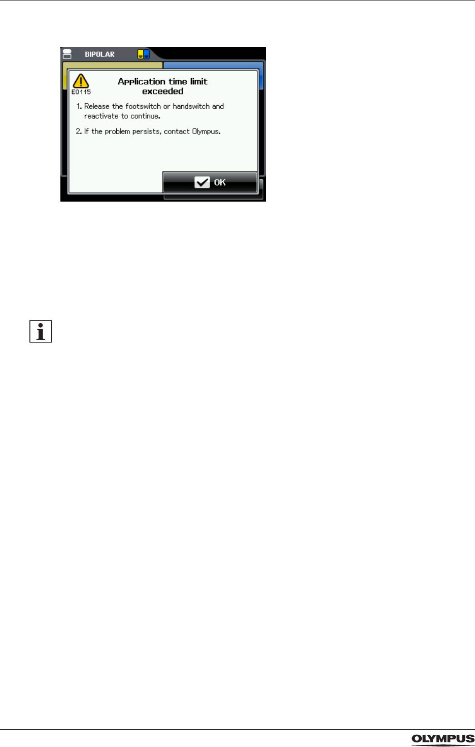
72
Operation
- The following error message is displayed:
Figure 10.1 Error message E0115: "Activation time limit exceeded"
To reactivate the electrosurgical generator proceed as follows:
1. Release the foot switch or hand switch.
- If Autostart is used, release the contact between the HF instrument and the tissue.
2. Then activate again.
- If Autostart is used, re-establish the contact between the HF instrument and the
tissue.
The activation time limit does not apply to RFITT modes.
10.2.3 Functional principles of activation
Screens for activation
Activation of power is possible only if the All Screen or the Set Screen is displayed on the
touch screen.
Activation of cutting and coagulation modes
All monopolar and bipolar cutting modes are activated as follows:
- By depressing the yellow cut pedal of the foot switch.
- By pressing the yellow cut trigger directly at the HF instrument.
All monopolar and bipolar coagulation modes are activated as follows:
- By depressing the blue coagulation pedal of the foot switch.
- By pressing the blue coagulation trigger directly at the HF instrument.
The output power is activated as long as the foot switch pedal or the hand switch at the HF
instrument is pressed.
DRAFT – 2017-01-17
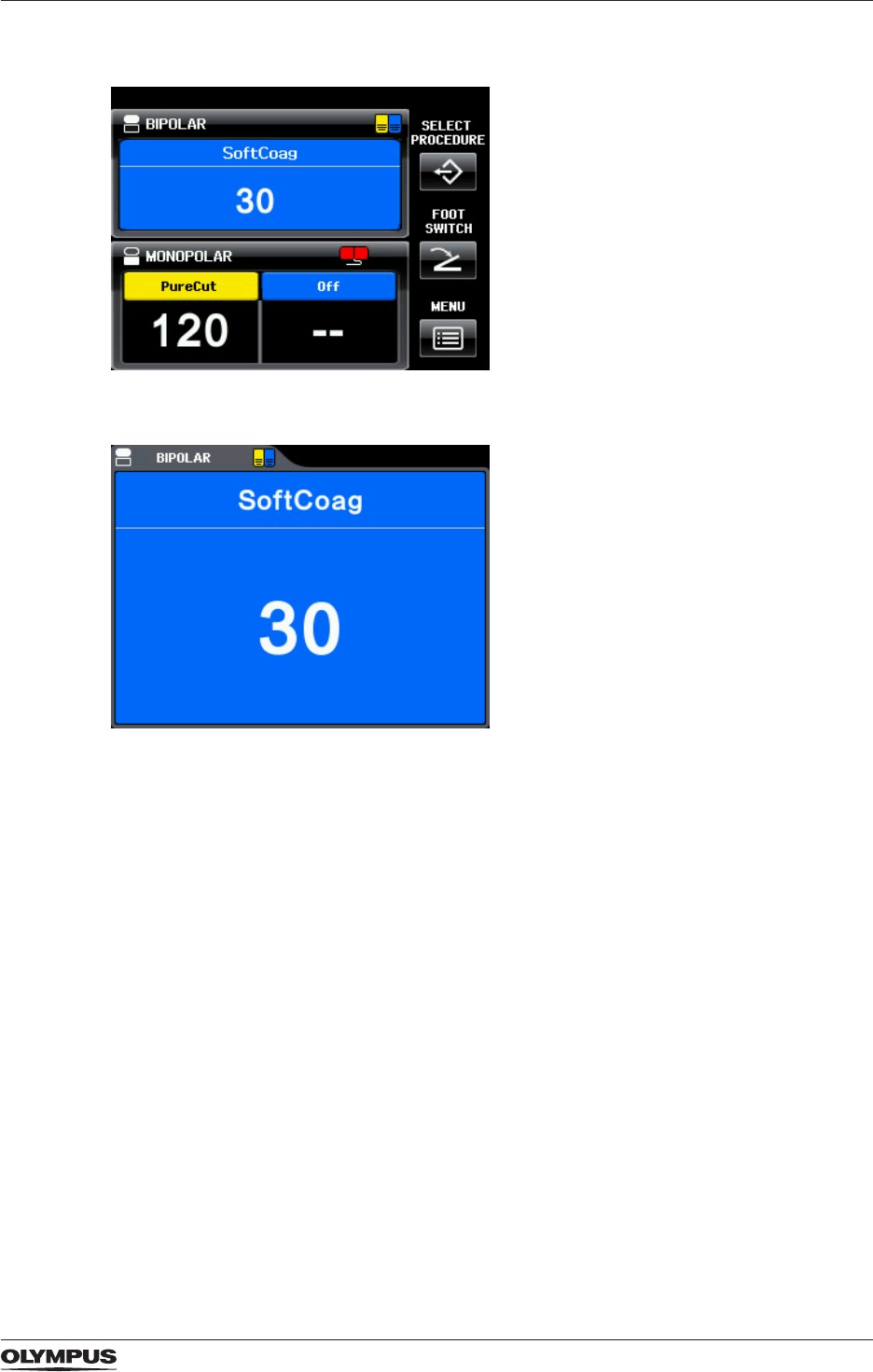
73
Operation
Background color
Figure 10.2 Background color for active coagulation on the All Screen
Figure 10.3 Background color for active coagulation on the Set Screen
During activation the background color of the touch screen adapts to the kind of output
power.
- For all cutting modes the background color changes to yellow.
- For all coagulation modes the background color changes to blue.
Output tone
During activation an output tone sounds.
DRAFT – 2017-01-17
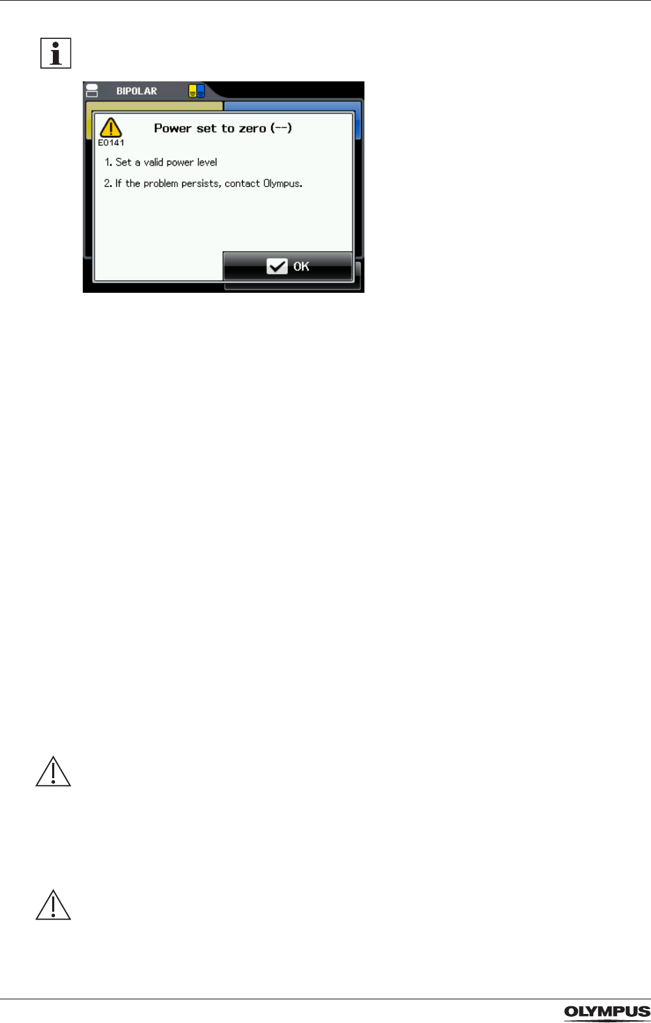
74
Operation
When attempting to activate although the output power level is set to 0, then an alarm tone
sounds and the following error message is displayed:
Figure 10.4 Error message E0141 "Power set to zero (--)"
• Conrm the message by tapping [OK] or wait for a few seconds and then continue.
Activation with Autostart for bipolar SoftCoag
The bipolar SoftCoag mode can be activated via Autostart if this is assigned to the
corresponding output socket.
• Refer to the section “Autostart for the bipolar mode SoftCoag” on page 22 for more
details on the Autostart feature.
• Refer to the section “Foot switch assignment and Autostart” on page 41 for instructions
on assigning Autostart.
• Refer to the section “Autostart Setup” on page 45 for instructions on setting a time delay
to Autostart.
Stopping activation
The output of power stops as soon the foot switch pedal or the hand switch is released.
When using Autostart for the bipolar mode SoftCoag, the output of power stops as soon as
the HF instrument is removed from the tissue.
10.3 After use
After each use, immediately perform the procedures as described in the following
paragraphs. If cleaning is delayed, debris encrustation may become a source of infection.
Encrustation may also result in malfunction of the electrosurgical generator.
WARNING
Protective clothing for cleaning and disinfection
Tissue debris and reprocessing chemicals represent a risk of infection for the reprocessing
personnel.
• During cleaning and disinfection wear appropriate personal protective clothing such as eye
wear, face mask, moisture-resistant clothing and surgical gloves that t properly.
• Before leaving the reprocessing area, remove the contaminated protective clothing.
WARNING
Drying
If the electrosurgical generator is stored or used after cleaning while still damp, then this can
result to electric shock to the patient and the user.
DRAFT – 2017-01-17

75
Operation
• Thoroughly dry the electrosurgical generator after cleaning.
CAUTION
Disconnection of plugs
Tugging and pulling at the cords can break the electric circuit and can damage the
equipment.
• When disconnecting equipment, directly pull at the plug.
• Do not tug or pull at the cords.
CAUTION
Cleaning and disinfecting
Immersing in liquids, gas sterilization or autoclaving will damage the electrosurgical
generator.
• Only use the cleaning and disinfection methods as described in the section
“Reprocessing” on page 76.
CAUTION
Sockets
Cleaning the sockets of the electrosurgical generator can deform and corrode the contacts
which will result in damage to the electrosurgical generator.
• Do not clean the output sockets, the power socket or the foot switch sockets.
CAUTION
Wiping the surface of the electrosurgical generator with abrasive cloths or abrasive
detergents damages the touch screen and rubs off the markings on the housing.
• Only use detergents as described in the section “Reprocessing” on page 76.
10.3.1 Disconnecting
To disconnect the electrosurgical generator from the mains electricity and to disconnect all
accessories from the electrosurgical generator proceed as follows:
1. Switch off the electrosurgical generator by pressing the power switch.
The light of the power switch and the touch screen turn off.
2. Disconnect all HF instruments from the corresponding output sockets.
3. Disconnect the connecting cable of the neutral electrode from the neutral electrode
socket.
4. Disconnect the cord set from the mains electricity.
5. Disconnect the foot switch from the socket at the rear panel of the electrosurgical
generator.
DRAFT – 2017-01-17

76
Reprocessing
11 Reprocessing
11.1 General information for reprocessing
Brand-new products
Treat brand-new products as if they have been used. Brand-new products must be
reprocessed using a complete reprocessing cycle.
The reprocessing cycle
• Reprocess the product according to the instructions in this chapter.
• To minimize the risk of infecting patients, users or third parties, reprocess the product
before each use.
• Contact your local hygiene representative for local standards and regulations.
Validated for efcacy
Validated for efcacy means that the efcacy of the method or agent has been validated for
reprocessing this product as described in this document.
Veried for material compatibility
Veried for material compatibility means that according to current knowledge the
reprocessing method or agent does not negatively affect materials or functional performance
of the product.
Veried for material compatibility does not mean that microbiological efcacy can be
guaranteed.
Instructions for using reprocessing agents
• The reprocessing agent must be approved by the manufacturer for cleaning and
disinfection of medical devices and for the material to bei reprocessed.
• Refer to national and local guidelines regarding the approval of using alcohol as
reprocessing agent.
• Select contact times and concentrations of the reprocessing agent in accordance with the
instructions given by the manufacturer.
• The reprocessing agent must be approved and validated by the FDA, the EPA, the DGHM
or a comparable institution for its efciency.
• Reprocessing may lead to an increased wear of the product. Before use, thoroughly
inspect the products for traces of wear.
11.2 Cleaning
Suitable reprocessing agents for cleaning
Cleaning efcacy has been validated with an alkaline disinfectant based on low alcohol
(<20%) and quaternary ammonium compounds (Sani-Cloth® Plus manufactured by PDI
Professional).
Material compatibility has been veried with the following reprocessing agents:
- Alkaline agents, max. pH value of 12,0
- Neutral agents
Cleaning procedure
Perform the following cleaning procedure immediately after use. If cleaning is delayed,
debris will solidify and it may be difcult to effectively clean the surfaces.
1. Take a soft, lint-free cloth that is soaked with a suitable reprocessing agent.
2. Thoroughly wipe the surfaces of the electrosurgical generator until visibly clean.
DRAFT – 2017-01-17

77
Reprocessing
3. In case of heavy soiling, use additional cloths.
4. Before disinfection, let the surfaces dry or wipe them dry using a lint-free cloth.
Inspection before disinfection
• Visually inspect the product thoroughly after cleaning.
The product must be visually clean.
• If the are any signs of debris, repeat the cleaning process.
11.3 Disinfection
Suitable disinfectants
Low-level disinfection efcacy has been validated with an alkaline disinfectant based on low
alcohol (<20%) and quaternary ammonium compounds (Sani-Cloth® Plus manufactured by
PDI Professional at 3 minutes contact time.)
Material compatibility has been veried with disinfectants based on the following as active
ingredients:
- Low alcohol
- Quaternary ammonium compounds
- Amine derivatives
- Sodium hypochlorite
Disinfection procedure
1. Take a soft, lint-free cloth that is soaked with a suitable disinfectant.
2. Thoroughly wet the surfaces of the electrosurgical generator.
3. The surfaces must remain visibly wet for the contact time that is designated by the
disinfectant's manufacturer.
4. Use additional cloths to assure the designated continuous wet contact time.
5. Let the surfaces dry or wipe them dry using a lint-free cloth.
11.4 Other HF equipment
• For the reprocessing or disposal of other HF equipment, e.g. neutral electrodes and HF
instruments, refer to the corresponding instructions for use of these products.
DRAFT – 2017-01-17

78
Troubleshooting
12 Troubleshooting
• If the problem cannot be resolved by the described remedial actions, stop using the
electrosurgical generator and contact Olympus.
• Be aware that repairs may only be performed by authorized service centers.
12.1 General problems
Check the following table to identify and correct failures. If the problem cannot be resolved
by the described remedial actions, contact Olympus.
Problem Cause Remedy
The electrosurgical
generator does not
respond when pressing
the power switch.
Improper connection of the cord set
to the socket on the rear panel of the
electrosurgical generator or to the
grounded mains electricity socket.
Check the cord set and the grounded
xed socket-outlet for correct
connection.
The grounded xed socket-outlet has
wrong or no output voltage.
Check the grounded xed socket-
outlet or use an alternative grounded
xed socket-outlet.
The cord set is damaged. Check the cord set for damages and,
if necessary, replace the cord set.
Malfunction of the electrosurgical
generator.
Do not use this electrosurgical
generator.
Contact Olympus.
After switching on
the electrosurgical
generator the touch
screen remains dark
but sounds are audible.
Malfunction of the touch screen. Do not use this electrosurgical
generator.
Contact Olympus.
The touch screen
cannot be controlled.
An object is in contact with the touch
screen.
Remove the object.
Malfunction of the touch screen. Do not use this electrosurgical
generator.
Contact Olympus.
There is no sound
coming from the
electrosurgical
generator during
activation.
The volume for the output tone is set
to an inaudible level, e.g. due to high
environmental noise.
Increase the volume either on the
screen [Select Menu] or use the
volume control on the rear panel of
the electrosurgical generator.
Malfunction of the electrosurgical
generator.
Do not use this electrosurgical
generator.
Contact Olympus.
The volume cannot be
adjusted on the screen
[Select Menu] or via
the volume control
on the rear panel of
the electrosurgical
generator.
The volume of error-related alarm
tones is not adjustable.
No action required.
Malfunction of the electrosurgical
generator.
Do not use this electrosurgical
generator.
Contact Olympus.
DRAFT – 2017-01-17

79
Troubleshooting
Problem Cause Remedy
The electrosurgical
generator does
not respond to foot
switch or hand switch
activation.
Improper contact of the connection
cable of the foot switch or the HF
instrument to the corresponding
socket of the electrosurgical
generator.
Check the connection cable of the
foot switch and the HF instrument for
correct connection.
The foot switch, the hand switch of
the HF instrument or their connection
cables are damaged.
Observe the foot switch, the hand
switch of the HF instrument and their
connection cables for damages. If
necessary, replace the foot switch, the
HF instrument or the corresponding
connection cable.
The wrong foot switch pedal or the
wrong hand switch is pressed.
Press the correct foot switch pedal
or the correct hand switch of the HF
instrument.
The electrosurgical generator is not
switched on.
Switch on the electrosurgical
generator with the power switch.
2 switches for activating the output
power are pressed simultaneously,
e.g. another foot switch pedal or hand
switch of an HF instrument.
Release all switches for activation
and check that no switch is pressed
unintentionally. Then activate the
output power using only 1 switch.
A message box is displayed on the
touch screen.
Tap [OK] or [Cancel] to close the
message box or wait until the
message box closes automatically
after a few seconds.
It is possible to activate the output
power only if either the All Screen or
the Set Screen is displayed on the
touch screen.
Return to the All Screen or the Set
Screen.
The output mode is deactivated ([Off]
is displayed) or the output power level
is set to 0 ([--] is displayed).
Activate the output mode on the Mode
Screen or increase the output power
level on the Set Screen. Refer to the
section “Selecting the appropriate
output settings” on page 62.
Malfunction of the electrosurgical
generator.
Do not use this electrosurgical
generator.
Contact Olympus.
Autostart is selected
and the HF instrument
has contact with
the tissue, but the
electrosurgical
generator does not
activate.
A long time delay for Autostart is set. Reduce the time delay for Autostart.
Refer to the section “Autostart Setup”
on page 45.
Malfunction of the electrosurgical
generator.
Do not use this electrosurgical
generator.
Contact Olympus.
DRAFT – 2017-01-17

80
Troubleshooting
Problem Cause Remedy
Foot switch pedal or
hand switch of the HF
instrument is pressed
and the output tone
sounds but no output
power is delivered.
The foot switch is assigned to another
output socket.
Check the correct assignment of the
foot switch. Refer to the section “Foot
switch assignment and Autostart” on
page 41.
Improper connection of the HF
instrument plug with the output socket
of the electrosurgical generator.
Check the plug of the HF instrument
for correct connection.
Malfunction of the electrosurgical
generator.
Do not use this electrosurgical
generator.
Contact Olympus.
No output power
is delivered when
an RFITT mode is
selected. The end-
of-procedure signal
sounds immediately
after activation.
The electrode has no contact with the
tissue.
Check that the electrode has contact
with the tissue.
Improper connection of the HF
instrument's plug with the output
socket of the electrosurgical
generator.
Check the plug of the HF instrument
for correct connection.
The HF instrument or its connection
cable is damaged.
Replace the HF instrument or its
connection cable.
Malfunction of the electrosurgical
generator.
Do not use this electrosurgical
generator.
Contact Olympus.
It is impossible to stop
the output power of
the electrosurgical
generator.
Autostart is assigned to the currently
used output socket and both
electrodes touch the tissue.
Remove the electrodes of the HF
instrument from the tissue.
Malfunction of the foot switch or hand
switch.
Immediately switch off the
electrosurgical generator by pressing
the power switch. Replace the foot
switch or the HF instrument with hand
switch.
Malfunction of the electrosurgical
generator.
Do not use this electrosurgical
generator.
Contact Olympus.
Its impossible to switch
off the electrosurgical
generator.
Malfunction of the electrosurgical
generator.
Disconnect the cord set plug from
the socket on the rear panel of the
electrosurgical generator and/or from
the grounded mains electricity socket.
Contact Olympus.
Do not use this electrosurgical
generator.
Table: Troubleshooting – General problems
12.2 Error messages
The electrosurgical generator is equipped with an intelligent alarm system. The alarm
system determines alarm conditions on the base of multiple variables.
DRAFT – 2017-01-17
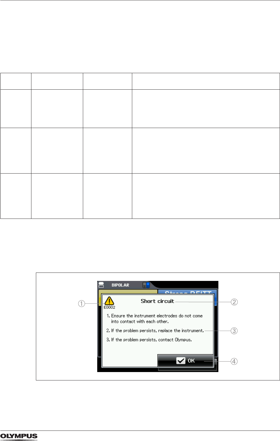
81
Troubleshooting
Alarm priorities
Depending on the potential risks, the alarms are classied in high, medium and low priority
alarms. An alarm of higher priority overrides an existing alarm of lower priority. If more
than one alarm condition of equal priority is determined, only the one that occurred rst is
reported.
The following table explains the three different conditions.
Alarm
priority
Alarm tone Display of
caution symbol
Meaning
High 3 short honks
and 2 long honks
for 2 cycles
The caution
symbol is red
and ashes.
- Serious system error.
- The output power is stopped automatically.
- The electrosurgical generator automatically restarts.
- If the restart runs successfully, then the user can
continue to use this electrosurgical generator.
Medium 3 short honks The caution
symbol is yellow
and ashes.
- With most medium priority alarms the output power
stops automatically.
- The user immediately needs to resolve the cause of
the error as explained in the error message.
- As soon as the error is resolved, the user can
continue to use this electrosurgical generator.
Low 2 short honks The caution
symbol is yellow
without ashing.
- The user needs to take notice of the error message.
- Possibly, the output power is stopped automatically
and the user needs to resolve the cause of the error
as explained in the error message.
- As soon as the error is resolved, the user can
continue to use this electrosurgical generator.
Table: Meaning of alarm priorities
Error messages
If an alarm condition occurs, then an alarm tone sounds and an error message is displayed
on the touch screen of the electrosurgical generator. The following gure shows an example:
Figure 12.1 Error message E0002 “Short circuit”
1) Caution symbol and error code
2) Error title
DRAFT – 2017-01-17

82
Troubleshooting
3) Remedial actions
4) Conrmation button
If the cause that released the alarm is cleared, then the error message is closed
automatically after approximately 10 seconds. If the cause of the alarm is not cleared, then
the error message stays on the touch screen.
• To clear the alarm, follow the instructions that are given in the error message.
It is possible to tap [OK] in the error message to close the error message faster.
12.2.1 Overview of error messages
The following table gives an overview of all error messages that possibly can be displayed.
The error messages are sorted numerically according to the error code.
Error code Message Cause Remedial action
E0001 Open circuit
1. Check if the electrodes
of the instrument have
proper tissue contact.
2. If the problem persists,
replace the instrument.
3. If the problem persists,
contact Olympus.
The electrodes of the HF
instrument have no tissue
contact.
Ensure that the electrodes
of the HF instrument have
proper tissue contact.
Malfunction of the HF
instrument or its connection
cable.
Replace the HF instrument
or its connection cable.
Malfunction of the
electrosurgical generator.
Do not use this
electrosurgical generator.
Contact Olympus.
E0002 Short circuit
1. Ensure the instrument
electrodes do not come
into contact with each
other.
2. If the problem persists,
replace the instrument.
3. If the problem persists,
contact Olympus.
The electrodes of the HF
instrument touch each other.
Ensure that the electrodes
of the HF instrument do not
touch each other.
Malfunction of the HF
instrument or its connection
cable.
Replace the HF instrument
or its connection cable.
Malfunction of the
electrosurgical generator.
Do not use this
electrosurgical generator.
Contact Olympus.
E0012 Adjustment incomplete
If the problem persists,
contact Olympus.
Malfunction of the
electrosurgical generator.
Do not use this
electrosurgical generator.
Contact Olympus.
E0016 Burn-in incomplete
If the problem persists,
contact Olympus.
Malfunction of the
electrosurgical generator.
Do not use this
electrosurgical generator.
Contact Olympus.
E0019 Connection of Footswitch
1. You can connect a double
pedal footswitch only.
2. If the problem persists,
contact Olympus.
A single pedal foot switch is
connected.
Disconnect the single pedal
foot switch.
Only connect the supplied
double pedal foot switch
(WB50402W).
Malfunction of the foot
switch.
Replace the foot switch.
Malfunction of the
electrosurgical generator.
Do not use this
electrosurgical generator.
Contact Olympus.
DRAFT – 2017-01-17

83
Troubleshooting
Error code Message Cause Remedial action
E0104
E0105
Footswitch pedal pressed
1. Release the footswitch
pedal to continue.
2. If the problem persists,
contact Olympus.
The foot switch pedal is
depressed while switching
on the electrosurgical
generator.
Release the foot switch
pedal.
Malfunction of the foot
switch.
Replace the foot switch.
Malfunction of the
electrosurgical generator.
Do not use this
electrosurgical generator.
Contact Olympus.
E0108
E0109
Handswitch pressed
1. Release the handswitch
of the instrument to
continue.
2. If the problem persists,
replace the instrument.
3. If the problem persists,
contact Olympus.
The hand switch of the
HF instrument is pressed
while switching on the
electrosurgical generator.
Release the hand switch of
the HF instrument.
Malfunction of the HF
instrument.
Replace the HF instrument.
Malfunction of the
electrosurgical generator.
Do not use this
electrosurgical generator.
Contact Olympus.
E0115 Application time limit
exceeded
1. Release the footswitch or
handswitch and reactivate
to continue.
2. If the problem persists,
contact Olympus.
The maximum time limit for
the application has been
exceeded.
Release the foot switch or
hand switch and reactivate
by pressing the foot switch
or hand switch again.
Malfunction of the
electrosurgical generator.
Do not use this
electrosurgical generator.
Contact Olympus.
E0136 Double pedal footswitch
not assigned
1. Assign the double
pedal foot switch to the
designated output socket.
2. If the problem persists,
contact Olympus.
The double pedal foot
switch is not assigned to the
corresponding output socket.
Assign the double pedal foot
switch to the corresponding
output socket. Refer to
the section “Foot switch
assignment and Autostart”
on page 41.
Malfunction of the
electrosurgical generator.
Do not use this
electrosurgical generator.
Contact Olympus.
E0140 No mode selected
1. Select a mode.
2. If the problem persists,
contact Olympus.
No mode has been selected. Select an appropriate mode.
Refer to the section “Output
settings” on page 59.
Malfunction of the
electrosurgical generator.
Do not use this
electrosurgical generator.
Contact Olympus.
E0141 Power set to zero (--)
1. Set a valid power level.
2. If the problem persists,
contact Olympus.
The output power level for
the chosen mode is set to 0.
Increase the output power
level on the Set Screen.
Refer to section “Selecting
the appropriate output
settings” on page 62.
Malfunction of the
electrosurgical generator.
Do not use this
electrosurgical generator.
Contact Olympus.
DRAFT – 2017-01-17

84
Troubleshooting
Error code Message Cause Remedial action
E0179 Temperature below limit
1. Switch off the
electrosurgical generator
and wait until operating
temperature is reached.
2. If the problem persists,
contact Olympus.
The minimum operating
temperature of the
electrosurgical generator
has fallen below the limit.
Switch off the electrosurgical
generator and wait until
the specied operating
temperature is reached.
Refer to the section
“Specications for the
CELON ELITE ESG-200” on
page 90.
Malfunction of the
electrosurgical generator.
Do not use this
electrosurgical generator.
Contact Olympus.
E0180 Temperature above limit
1. Switch off the
electrosurgical generator
and wait until it has
cooled down.
2. If the problem persists,
contact Olympus.
The maximum operating
temperature of the
electrosurgical generator
has been exceeded.
Switch off the electrosurgical
generator and let it cool
down until the specied
operating temperature is
reached. Refer to the section
“Specications for the
CELON ELITE ESG-200” on
page 90.
Malfunction of the
electrosurgical generator.
Do not use this
electrosurgical generator.
Contact Olympus.
E0187 Increased HF leakage
current
1. Check if an instrument,
the neutral electrode or
patient is unintentionally
grounded.
2. If the problem persists,
contact Olympus.
The high frequency leakage
current has exceeded
the limit of 150 mA for
monopolar applications
or 100 mA for bipolar
applications.
Check if the electrosurgical
generator or the patient is
grounded unintentionally.
Malfunction of the
electrosurgical generator.
Do not use this
electrosurgical generator.
Contact Olympus.
E0188 Excessive HF leakage
current
1. Check if an instrument,
the neutral electrode or
patient is unintentionally
grounded.
2. If the problem persists,
contact Olympus.
The high frequency leakage
current has exceeded
the limit of 300 mA for
monopolar applications
or 200 mA for bipolar
applications.
Check if the electrosurgical
generator or the patient is
grounded unintentionally.
Malfunction of the
electrosurgical generator.
Do not use this
electrosurgical generator.
Contact Olympus.
E0202 Insufcient neutral
electrode contact
1. Check the connection and
attachment of the neutral
electrode.
2. If the problem persists,
attach a new neutral
electrode.
3. If the problem persists,
contact Olympus.
The contact resistance of
the neutral electrode is too
high or the neutral electrode
is not connected.
Check the connection and
attachment of the neutral
electrode.
Malfunction of the neutral
electrode or its connection
cable.
Replace the neutral
electrode or its connection
cable.
Malfunction of the
electrosurgical generator.
Do not use this
electrosurgical generator.
Contact Olympus
DRAFT – 2017-01-17

85
Troubleshooting
Error code Message Cause Remedial action
E0214 Low battery
If the problem persists,
contact Olympus.
Malfunction of the
electrosurgical generator.
Do not use this
electrosurgical generator.
Contact Olympus.
E0438 Procedure data error
1. One or more procedures
have been deleted. Press
OK to continue.
2. If the problem persists,
contact Olympus.
One or more saved
procedures are deleted.
Tap [OK] to close the error
message and to continue.
Malfunction of the
electrosurgical generator.
Do not use this
electrosurgical generator.
Contact Olympus.
E0441 Device setting error
Device settings have been
set to default.
If the problem persists,
contact Olympus.
All settings of the
electrosurgical generator are
set to default.
The electrosurgical
generator is ready for use
after the error message is
closed.
Malfunction of the
electrosurgical generator.
Do not use this
electrosurgical generator.
Contact Olympus.
E0660 No bipolar cutting
For safety reasons the
bipolar cutting modes cannot
be activated while an RFITT
mode is selected.
A bipolar cutting mode as
well as a bipolar RFITT
mode are selected.
Switch off the bipolar RFITT
mode or select the mode
SoftCoag.
E0683 No compatible RFITT
instrument connected
RFITT modes can only be
activated if a compatible
RFITT instrument is
connected.
There is no or an
incompatible HF instrument
connected.
Connect an HF instrument
that is compatible with this
electrosurgical generator
and its RFITT modes.
E0687 Instrument wearout note
The instrument is about to
reach its maximum usage
time.
Replace the instrument if
possible.
The permitted usage span of
the HF instrument is nearly
reached. The error message
is repeated after every new
activation.
Replace the HF instrument
as soon as the treatment
situation allows.
E0688 Instrument wearout
warning
The instrument has
exceeded its maximum
usage time.
Replace the instrument to
proceed.
The permitted usage span
of the HF instrument is
exceeded. It is impossible to
activate this HF instrument
anymore.
Replace the HF instrument.
E0689 Refer to error code E0687.
E0690 Refer to error code E0688.
E0### Error
Electrosurgical generator will
automatically restart.
If the problem persists,
contact Olympus.
Malfunction of the
electrosurgical generator.
The electrosurgical
generator automatically
restarts.
If any error occurs
permanently or repetitively,
contact Olympus.
Table: Troubleshooting – Overview of error messages
DRAFT – 2017-01-17

86
Maintenance, repair and shipment
13 Maintenance, repair and shipment
13.1 Annual safety check
The electrosurgical generator as well as the foot switch must go through an annual safety
check in accordance with the national statutory regulations.
The annual safety check may only be carried out by a qualied electrician with sufcient
experience in maintaining medical electrical devices. Furthermore, the appropriate
equipment for performing the safety check must be available. Details on the annual safety
check are described in the maintenance manual for the CELON ELITE ESG-200.
• Contact the local Olympus representative for the latest version of the maintenance
manual.
Alternatively, the electrosurgical generator can be sent to an authorized service center
where the annual safety check is carried out.
• Contact the local Olympus representative for information on authorized service centers.
• When sending the electrosurgical generator to an authorized service center, take account
of the information in the section “Shipment” on page 86.
13.2 Repair
Repairs may only be performed by authorized service centers.
• Do not attempt to modify or repair the electrosurgical generator or the foot switch.
• Contact the local Olympus representative center for repair and warranty information.
• When sending the electrosurgical generator to an authorized service center, take account
of the information in the section “Shipment” on page 86.
13.3 Shipment
When sending products to an authorized service center for repair, maintenance or warranty
claims, note the following:
Risk of infection
Used products represent a risk of infection for the servicing personnel. Service centers are
entitled to refuse the service for soiled or contaminated products for reasons of safety.
• Clean and disinfect the product as thoroughly as possible and mark it accordingly.
Packaging
Service centers do not accept warranty claims for damage caused by inadequate packaging.
• Use the original cardboard packaging for the transport of the product.
• If this is not possible, wrap each component individually in sufcient paper or sheets of
foamed material and place them in a cardboard box.
Description of malfunction and contact person
When returning the electrosurgical generator:
• Include a description of the malfunction or damage.
• State the name and telephone number of a contact person.
DRAFT – 2017-01-17
87
Storage and disposal
14 Storage and disposal
14.1 Storage
CAUTION
Storage
Exposing the electrosurgical generator to strong impacts, direct sunlight, x-rays,
radioactivity, liquids or strong magnetic radiation can damage the electrosurgical generator.
• Do not store the electrosurgical generator in a location that is exposed to direct sunlight,
x-rays, radioactivity or liquids.
• Do not store the electrosurgical generator in a location that is exposed to strong
electromagnetic radiation, e.g. microwave medical treatment equipment, short-wave
medical treatment equipment, magnetic resonance imaging equipment, radio or mobile
phones.
• Do not subject the electrosurgical generator to strong impacts during storage.
During storage
• Place the electrosurgical generator and the foot switch on a stable, level surface.
• Store the electrosurgical generator and the foot switch according to the environmental
conditions described in the chapter “Specications” on page 90.
14.2 Disposal
When disposing of the product or any of its components, e.g. fuses or packaging material,
follow all applicable national and local laws and guidelines.
Waste electrical and electronic equipment
In accordance with European Directive 2002/96/EC on waste electrical and electronic
equipment (WEEE), the product must not be disposed of as unsorted municipal waste, but
should be collected separately.
For nationally available return or collection systems contact the Olympus representative.
DRAFT – 2017-01-17
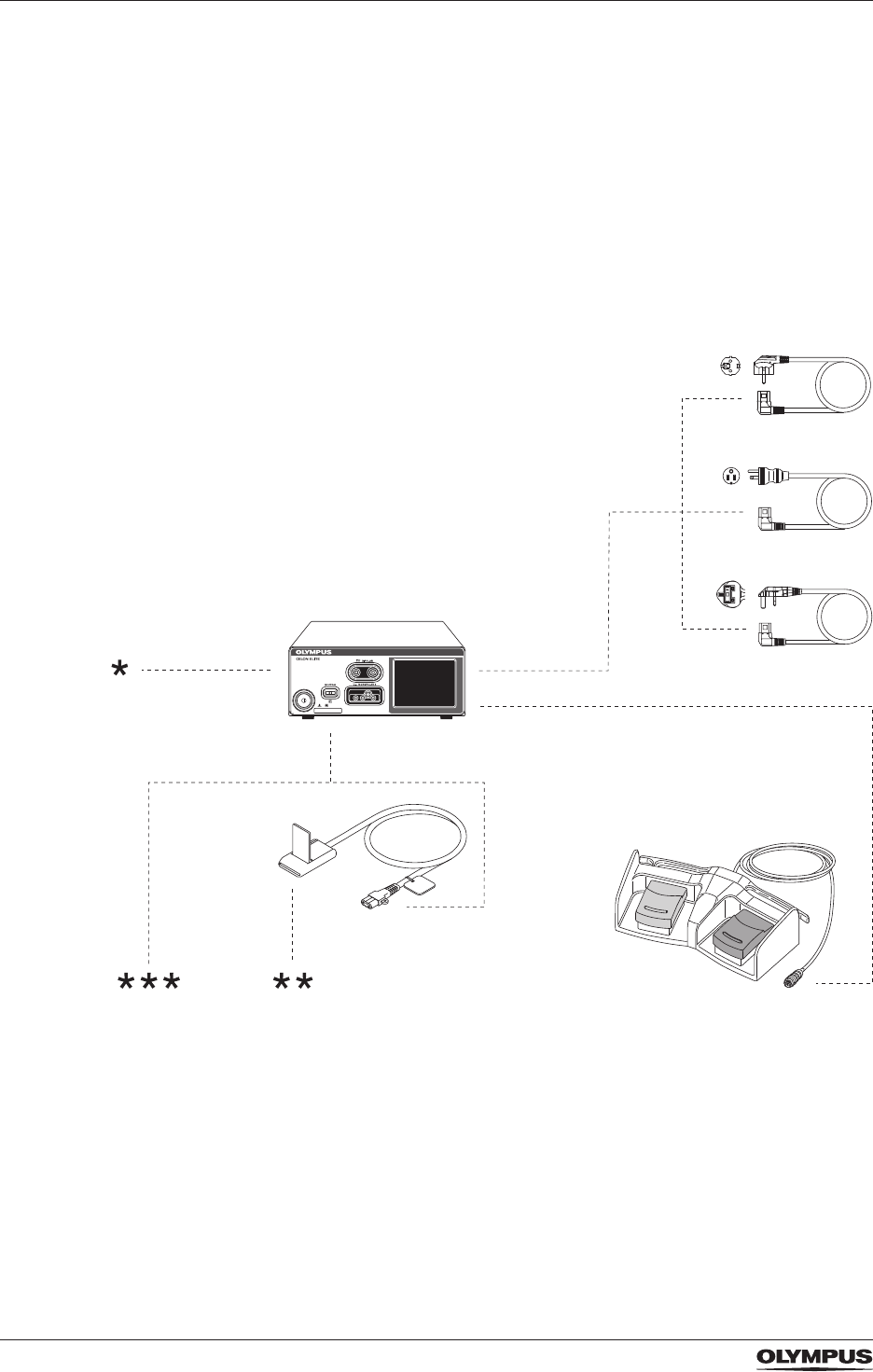
88
Compatible equipment
15 Compatible equipment
Olympus recommends the use of equipment as listed in this chapter. If combinations are
used that are not listed in this chapter, the user takes the full responsibility.
Future equipment may also be compatible. For more information, contact an Olympus
representative.
Some of the products listed in this chapter may not be available in all sales territories.
15.1 System chart
Figure 15.1 System chart for CELON ELITE ESG-200
* Bipolar and monopolar HF instruments including compatible HF cables
** Split type neutral electrodes without connecting cable
*** Split type neutral electrodes with connecting cable
CELON ELITE ESG-200
WA95621A
WA95622A
WA95623A
WB50402W
MAJ-814
ESG-200
DRAFT – 2017-01-17

89
Compatible equipment
15.2 Compatible neutral electrodes
Name Description
3M 1180
- Patient weight >15 kg
- Split type
- White foam
3M 1179
- Patient weight >15 kg
- Split type
- White foam
- With cable
3M 8180
- Patient weight >15 kg
- Split type
- Teal foam
- Soft conductive adhesive
3M 9160
- Patient weight <15 kg
- Split type
- Safety ring
- Soft backing
3M 9165
- Patient weight <15 kg
- Split type
- Safety ring
- Soft backing
- With cable
Valleylab E7509
- Patient weight >15 kg
- Split type
- Soft conductive adhesive
Valleylab E7507
- Patient weight >15 kg
- Split type
- Soft conductive adhesive
- With cable
Valleylab E7510-25
- Patient weight <15 kg
- Split type
- Soft conductive adhesive
Conmed SureFit 410-2000/410-2100
- Patient weight <15 kg
- Split type
- With cable
Conmed SureFit 410-2200/410-2400 - Patient weight <15 kg
- Split type
Table: Compatible neutral electrodes
DRAFT – 2017-01-17

90
Specications
16 Specications
Specications, design and accessories are subject to change without any notice or any
obligation of the manufacturer.
16.1 Specications for the CELON ELITE ESG-200
Size
Width ...............................................................................................................295 mm
Height ..............................................................................................................115 mm
Depth ...............................................................................................................400 mm
Volume .......................................................................................................13,570 cm³
Weight ..............................................................................................................6.61 kg
Packaging
Weight of packaging ...........................................................................................1.5 kg
Type of packaging ..........................cardboard and expanded polypropylene material
Power supply
Voltage range .................................................. AC 100 V to 120 V/AC 220 V to 240 V
Frequency ............................................................................................... 50 Hz/60 Hz
Maximum input power ..................................................................................... 650 VA
Fuse .............................................................................................................. T 6.3 AH
Classications
According to IEC 60601-1, protection against electric shock:
Medical electrical equipment .............................................................................Class I
Applied parts ................................................................................................. Type CF
Protection against harmful ingress of water .........................................................IPX0
Mode of operation ...............................Continuous operation with intermittent loading
According to Medical Device Directive 93/42/EEC ...................................................IIb
Output
High frequency functions..........................................................Monopolar and bipolar
High frequency ..................................................................................... 356 kHz ±20%
Maximum HF power .......................................................................................... 120 W
All modes ......................25% duty cycle (e.g. activated for 10 s, deactivated for 30 s)
All RFITT modes ............................................................................... 100% duty cycle
RFID technology
The device contains radio-frequency identication (RFID) technology.
Frequency band: ...........................................13,56 MHz (internationally harmonized)
Ambient conditions for operation, storage and transport
Operating temperature ..............................................+10 to +40 °C (+50 to +104 °F)
Storage and transport temperature .............................-25 to +60 °C (-13 to +140 °F)
Relative operating humidity ............................................. 30 to 85 %, non-condensing
Relative storage and transport humidity ..........................10 to 85 %, non-condensing
Atmospheric operating pressure ........................................................... 70 to 106 hPa
Atmospheric storage and transport pressure ........................................ 50 to 106 hPa
DRAFT – 2017-01-17

91
Specications
Plug requirements for the MONOPOLAR output socket
WA90001A
3-pin plugs............................................Pin∅ 4 mm (international/Valleylab standard)
Coaxial plugs................................................................Pin∅ 9/5 mm (Erbe standard)
1-pin plugs................................................................................................ Pin∅ 4 mm
WA90002A
3-pin plugs............................................Pin∅ 4 mm (international/Valleylab standard)
1-pin plugs..................................................................... Pin∅ 8 mm (Bovie standard)
1-pin plugs................................................................................................ Pin∅ 4 mm
Plug requirements for the BIPOLAR output socket
2-pin plugs.................................................................................................Pin∅ 4 mm
28.6 mm pin spacing (international/Valleylab standard)
Coaxial plugs................................................................Pin∅ 4/8 mm (Erbe standard)
Plug requirements for the neutral electrode socket
........................................................................ 2 pins, ∅ 2.5 mm, 10 mm pin spacing
Allowable resistance range for the Contact Quality Monitor – CQM
For split type neutral electrodes ................................................ 10 ±5 Ω to 155 ±15 Ω
For non-split type neutral electrodes .............................................................<10 ±5 Ω
16.2 Specications for the double pedal foot switch (WB50402W)
Manufacturer
Olympus Winter & Ibe GmbH, Kuehnstr. 61, 22045 Hamburg, Germany
Power
Voltage .......................................................................................................... DC 24 V
Electric current .................................................................................................... 0.1 A
Classications
Protection class according to IEC 60529 ...................IPX8 (except the plug sections)
Size
Width ...............................................................................................................350 mm
Height ................................................................................................................65 mm
Depth ...............................................................................................................185 mm
Weight ................................................................................................................1.9 kg
Length of connection cable ...................................................................................4 m
Packaging
Weight of packaging ...........................................................................................0.5 kg
Type of packaging .........................................................................cardboard material
16.3 Specications for the cord set
WA95621A (for many European countries) ................................................... Type E/F
WA95622A (for Canada, USA and other countries) ..........................................Type B
WA95623A (for United Kingdom and other countries) ..................................... Type G
Length .................................................................................................................4.5 m
Plug on device side ...........................................................................................angled
DRAFT – 2017-01-17
92
Electromagnetic compatibility
17 Electromagnetic compatibility
Le présent appareil est conforme aux CNR d’ISED applicables aux appareils radio exempts
de licence.
L’exploitation est autorisée aux deux conditions suivantes :
1. l’appareil ne doit pas produire de brouillage,
2. l’appareil doit accepter tout brouillage radioélectrique subi, même si le brouillage est
susceptible d’en compromettre le fonctionnement.
Precautionary measures
Electromedical devices are subject to special precautionary measures concerning
electromagnetic compatibility (EMC). This device is to be used only for the purposes
described in these instructions for use and has to be installed, set up, and operated in
compliance with the EMC guidelines.
Impact of mobile and portable RF communication devices
The emission of radio frequency energy by mobile communication devices may impact the
function of the electromedical device. Operating such mobile communication devices (e.g.
cell phones, GSM phones) in the proximity of the electromedical device is prohibited.
Electrical connections
Electrical connections bearing this warning symbol may not be touched. Connections
between such plugs and sockets may not be established without rst implementing ESD
precautionary measures.
ESD precautionary measures
The following are ESD precautionary measures:
• Connect all electrical equipment to be connected to the device to a potential equalisation
system (via PE).
• Use only the equipment and accessories mentioned in these instructions for use.
The staff have to be informed about and trained in ESD precautionary measures.
Guidelines and manufacturer’s declaration – electromagnetic emissions
This device is intended for use in the electromagnetic environment specied below. The customer or the
user of this device should assure that it is used in such an environment.
Emissions test Compliance Electromagnetic environment – guidance
RF emissions
CISPR 11
Group 1 During standby this device uses RF energy only for its internal
function. Therefore, its RF emissions are very low and are not likely
to cause any interference in nearby electronic equipment.
RF emissions
CISPR 11
Class B This device is suitable for use in all facilities including those in
residential areas and those directly connected to a public supply
network that also supplies buildings used for residential purposes.
Harmonic
emissions
IEC 61000-3-2
Class B
Voltage
uctuations/
icker emissions
IEC 61000-3-3
In
compliance
DRAFT – 2017-01-17

93
Electromagnetic compatibility
Guidelines and manufacturer’s declaration – electromagnetic immunity
This device is intended for use in the electromagnetic environment specied below. The customer or the
user of this device should assure that it is used in such an environment.
Immunity test IEC 60601 test
level
Compliance
level
Electromagnetic environment – guidance
Electrostatic
discharge (ESD)
IEC 61000-4-2
± 6 kV contact
discharge
± 8 kV air
discharge
Identical to
test level
Floors should be wood, concrete or ceramic tile.
If oors are covered with synthetic material, the
relative humidity should be at least 30%.
Electrical fast
transient/burst
IEC 61000-4-4
± 2 kV for power
supply lines
± 1 kV for input/
output lines
Identical to
test level
Mains power quality should be that of a typical
commercial or hospital environment.
Surges
according to
IEC 61000-4-5
± 1 kV line(s) to
line(s)
± 2 kV line(s) to
earth
Identical to
test level
Mains power quality should be that of a typical
commercial or hospital environment.
Voltage
dips, short
interruptions
and voltage
variations on
power supply
input lines
according to
IEC 61000-4-11
< 5% UT* (> 95%
dip in UT) for
0.5 cycle
40% UT (60%
dip in UT) for
5 cycles
70% UT (30%
dip in UT) for
25 cycles
< 5% UT (> 95%
dip in UT) for 5 s
Identical to
test level
Mains power quality should be that of a typical
commercial or hospital environment. If the user of
this device requires continuous operation during
power mains interruptions, it is recommended
that the device is powered from an uninterruptible
power supply or a battery.
Magnetic
elds of mains
frequency
(50/60 Hz)
magnetic eld
IEC 61000-4-8
3 A/m Identical to
test level
Power frequency magnetic elds should be at
levels characteristic of a typical location in a
typical commercial or hospital environment.
*Note: UT is the a.c. mains voltage prior to application of the test level.
DRAFT – 2017-01-17
94
Electromagnetic compatibility
Guidance and manufacturer’s declaration – electromagnetic immunity
This device is intended for use in the electromagnetic environment specied below. The customer or
user of this device should assure that it is used in such an environment.
Immunity test IEC 60601
test level
Compliance
level
Electromagnetic environment – guidance
Conducted RF
according to
IEC 61000-4-6
3 Veff
150 kHz to
80 MHz
3 V Portable and mobile RF communications equipment
should be used no closer to any part of the Olympus
CELON ELITE ESG-200, including cables, than the
recommended separation distance calculated from the
equation applicable to the frequency of the transmitter.
Recommended separation distance
d = 1.2 √ P
d = 1.2 √ P 80 MHz to 800 MHz
d = 2.3 √ P 800 MHz to 2.5 GHz
where P is the maximum output power rating of the
transmitter in watts [W] according to the transmitter
manufacturer and d is the recommended separation
distance in meters [m].
Field strengths from xed RF transmitters, as determined
by an electromagnetic site surveya, should be less than the
compliance level in each frequency rangeb.
Interference may occur in the vicinity of equipment marked
with the following symbol:
Radiated RF
according to
IEC 61000-4-3
3 V/m
80 MHz to
2.5 GHz
3 V/m
Note 1: At 80 MHz and 800 MHz, the higher frequency range applies.
Note 2: These guidelines may not apply in all situations. Electromagnetic propagation is
affected by absorption and reection from structures, objects and people.
a Field strengths from xed transmitters, such as base stations for radio (cellular/cordless)
telephones and land mobile radios, amateur radio, AM and FM radio broadcast and TV
broadcast cannot be predicted theoretically with accuracy. To assess the electromagnetic
environment due to xed RF transmitters, an electromagnetic site survey should be
considered. If the measured eld strength in the location in which the Olympus CELON
ELITE ESG-200 is used exceeds the applicable RF compliance level above, the Olympus
CELON ELITE ESG-200 should be observed to verify normal operation. If abnormal
performance is observed, additional measures may be necessary, such as re-orienting or
relocating the device.
b Over the frequency range 150 kHz to 80 MHz, eld strengths should be less than 3 V/m.
Recommended separation distances between portable and mobile RF communications
equipment and this device
This device is intended for use in an electromagnetic environment in which radiated RF disturbances
are controlled. The customer or user of this device can help prevent electromagnetic interference
by maintaining a minimum distance between portable and mobile RF communications equipment
(transmitters) and this device as recommended below, according to the maximum output power of the
communications equipment.
DRAFT – 2017-01-17
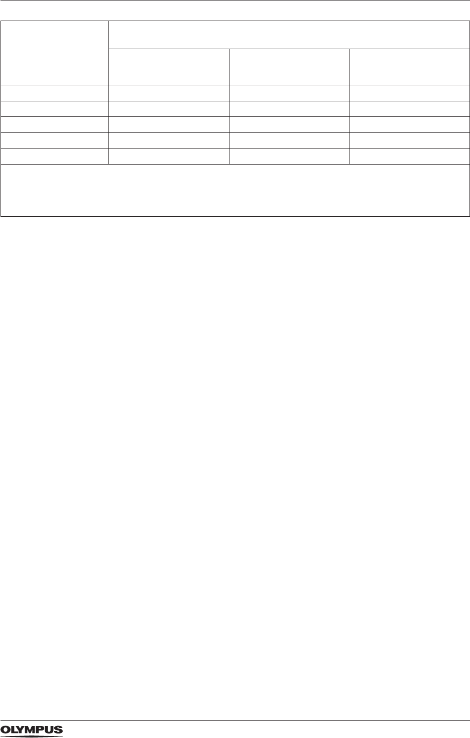
95
Electromagnetic compatibility
Rated output power
of the transmitter
P in W
Separation distance (d) according to frequency of the transmitter in
meters (m)
150 kHz to 80 MHz
d = 1.2 √ P
80 MHz to 800 MHz
d = 1.2 √ P
800 MHz to 2.5 GHz
d = 2.3 √ P
0.01 0.12 m 0.12 m 0.23 m
0.1 0.38 m 0.38 m 0.73 m
1 1.2 m 1.2 m 2.3 m
10 3.8 m 3.8 m 7.3 m
100 12 m 12 m 23 m
For transmitters rated at a maximum output power not listed above, the recommended separation
distance [d] in metres [m] can be estimated using the equation applicable to the frequency of the
transmitter, where P is the maximum output power rating of the transmitter in watts [W] according to the
transmitter manufacturer.
Note 1: For 80 MHz and 800 MHz, the separation distance for the higher frequency range
applies.
Note 2: These guidelines may not apply in all situations. Electromagnetic propagation is
affected by absorption and reection from structures, objects and people.
DRAFT – 2017-01-17
DRAFT – 2017-01-17

97
Appendix A
APPENDIX A
Alarm system
An alarm condition is indicated about one second after detection and securing.
Log le for alarm conditions
The alarm system provides a log of occurrences of alarm conditions. The eldest
log is overwritten by the latest log when the capacity of 4098 logs is reached. Only
authorized service personnel can read log data.
If the alarm system is powered down, then the log is still maintained by an internal
electrical power source. In case of a total loss of power, i.e. mains electricity as well
as internal power source, the complete log is erased immediately.
Alarm tones
Depending on the priority of an error, the alarm tones sound different.
High priority errors
E0004, E0008...E0011, E0013, E0015, E0018, E0024...E0037, E0039...E0102,
E0116...E0119, E0122...E0133, E0137, E0142...E0178, E0197, E0198, E0203...
E0211, E0213, E0216...E0412, E0415...E0437, E0439, E0440, E0443...E0455,
E0458...E0484, E0492...E0605, E0620...E0659, E0662...E0664, E0672...E0680,
E0682, E0684...E0686, E0691, E0697
For these error codes the following values apply:
Duty cycle .................................................... Intermitting signal (number of burst = 10)
Frequency ................................................................................................. 200/300 Hz
Volume ...................................................................................................... ≥ 65 dB (A)
Medium priority errors
E0012, E0016, E0017, E0019...E0022, E0038, E0104, E0105, E0108, E0109,
E0120, E0121, E0134, E0136, E0179...E0186, E0188...E0196, E0199...E0201,
E0212, E0215, E0413, E0414, E0438, E0457, E0488, E0489, E0665, E0681
For these errors codes the following values apply:
Duty cycle ...................................................... Intermitting signal (number of burst = 3)
Frequency ................................................................................................. 200/300 Hz
Volume ...................................................................................................... ≥ 65 dB (A)
Low priority errors
E0001, E0002, E0006, E0115, E0140, E0141, E0187, E0202, E0214, E0441,
E0619, E0660, E0683, E0687...E0690, E0698
For these errors codes the following values apply:
Duty cycle ...................................................... Intermitting signal (number of burst = 2)
Frequency ................................................................................................. 200/300 Hz
Volume ...................................................................................................... ≥ 65 dB (A)
DRAFT – 2017-01-17

98
Appendix A
Output tone information
Monopolar modes
Mode Frequency Duty cycle Volume
FineCut 587 Hz Continuous signal ≥40 to ≥65 dB (A)
PureCut 587 Hz Continuous signal ≥40 to ≥65 dB (A)
StrongCut 587 Hz Continuous signal ≥40 to ≥65 dB (A)
Pulse Cut 440 Hz / 494 Hz Alternating signal ≥40 to ≥65 dB (A)
SoftCoag 440 Hz Continuous signal ≥40 to ≥65 dB (A)
ForcedCoag 554 Hz Continuous signal ≥40 to ≥65 dB (A)
Output tone information for monopolar modes
DRAFT – 2017-01-17

99
Appendix A
Bipolar modes
Mode Frequency Duty cycle Volume
FineCut 587 Hz Continuous signal ≥40 to ≥65 dB (A)
PureCut 587 Hz Continuous signal ≥40 to ≥65 dB (A)
StrongCut 587 Hz Continuous signal ≥40 to ≥65 dB (A)
SoftCoag 440 Hz Continuous signal ≥40 to ≥65 dB (A)
Pure RFITT
469 Hz < f <
1038 Hz depending
on tissue resistance
Continuous signal ≥40 to ≥65 dB (A)
End signal:
2000 Hz
Intermitting (500 ms
on, 500 ms off)
Fine RFITT
469 Hz < f <
1038 Hz depending
on tissue resistance
Continuous signal ≥40 to ≥65 dB (A)
End signal:
2000 Hz
Intermitting (500 ms
on, 500 ms off)
Strong RFITT
469 Hz < f <
1038 Hz depending
on tissue resistance
Continuous signal ≥40 to ≥65 dB (A)
End signal:
2000 Hz
Intermitting (500 ms
on, 500 ms off)
Strong
RFITT+RCAP
469 Hz Continuous signal ≥40 to ≥65 dB (A)
End signal:
2000 Hz
Intermitting (500 ms
on, 500 ms off)
Output tone information for bipolar modes
Touch tone and start melody
Touch tone
Duty cycle ........................................................................................................... 0.09 s
Frequency ........................................................................................................ 500 Hz
Volume ....................................................................................................... ≥65 dB (A)
Start melody
Duty cycle ......................................................................................................... 0.375 s
Volume ....................................................................................................... ≥65 dB (A)
DRAFT – 2017-01-17
DRAFT – 2017-01-17
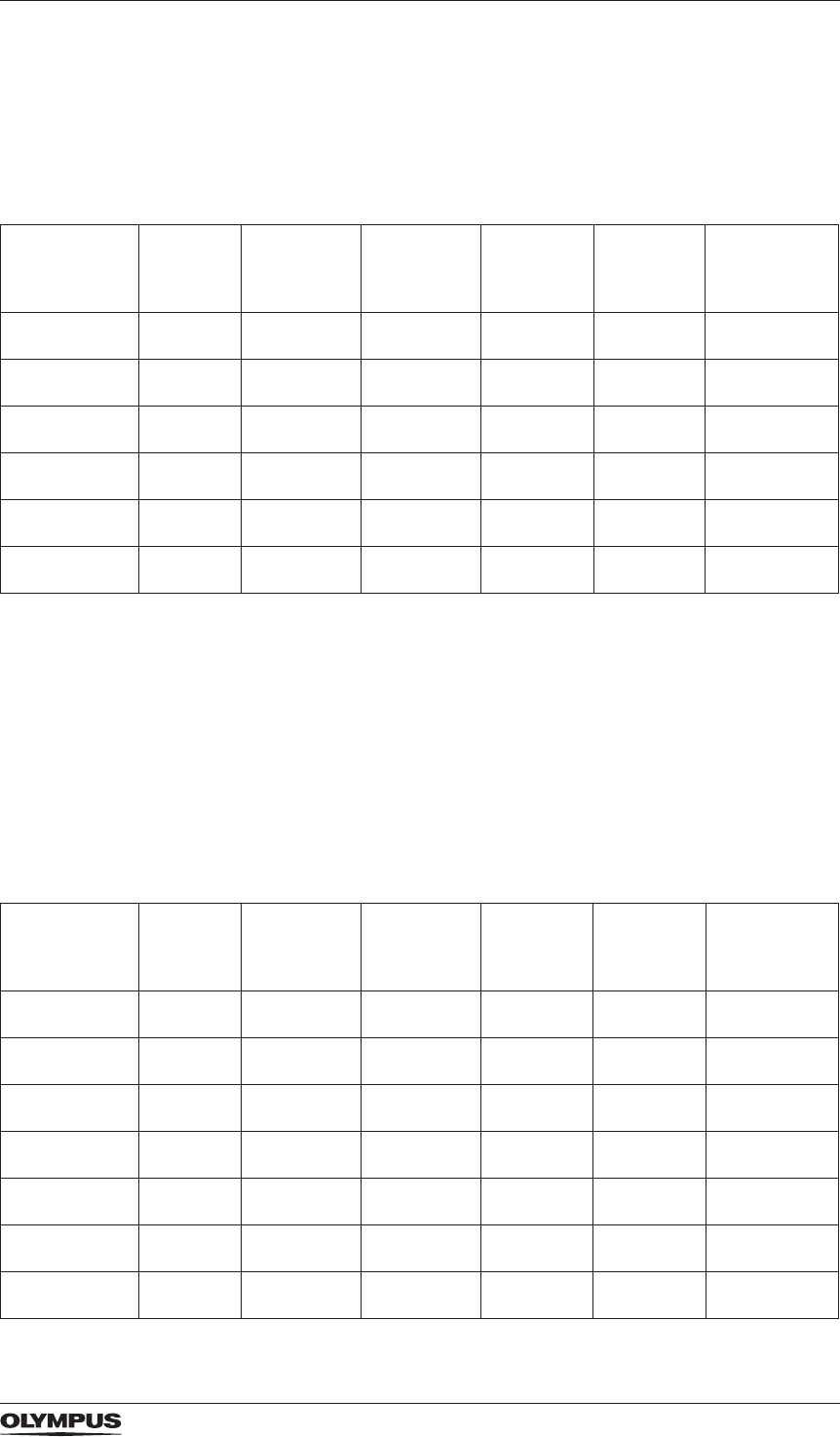
101
Appendix B
APPENDIX B
Mode characteristics according to IEC 60601-2-2
Mode characteristics of monopolar modes
The waveforms of all monopolar modes are continuous, except of ForcedCoag1).
Mode Default
power
setting
Minimum
power
level3)
Maximum
power
level3)
Maximum
output
voltage
Rated
load
End-of-
procedure
load
FineCut 30 5 W 120 W 580 Vp500 Ω —
PureCut 30 5 W 120 W 630 Vp500 Ω —
StrongCut 30 5 W 120 W 680 Vp500 Ω —
Pulse Cut 30 5 W 120 W 690 Vp500 Ω —
SoftCoag 30 5 W 120 W 250 Vp100 Ω —
ForcedCoag 2) 30 5 W 120 W 2000 Vp500 Ω —
Mode characteristics for monopolar modes
1) Waveform ........................................................................... Modulated sinus, 15 kHz
2) Crest factor at rated load ............................................................................3.0 to 8.0
3) The power level is the continuous power (Watts) which can be applied during the
activation of the electrosurgical generator. The actual applied power depends on the
tissue characteristics, e.g. resistance.
Mode characteristics of bipolar modes
The waveforms of all bipolar modes are continuous.
Mode Default
power
setting
Minimum
power
level1)
Maximum
power
level1)
Maximum
output
voltage
Rated
load
End-of-
procedure
load
FineCut 30 5 W 120 W 470 Vp500 Ω —
PureCut 30 5 W 120 W 530 Vp500 Ω —
StrongCut 30 5 W 120 W 560 Vp500 Ω —
SoftCoag 30 5 W 120 W 260 Vp100 Ω —
Fine RFITT 10 1 W 40 W 250 Vp100 Ω dynamic
Pure RFITT 10 1 W 40 W 150 Vp100 Ω 400 Ω
Strong RFITT 20 1 W 40 W 260 Vp100 Ω 900 Ω
DRAFT – 2017-01-17
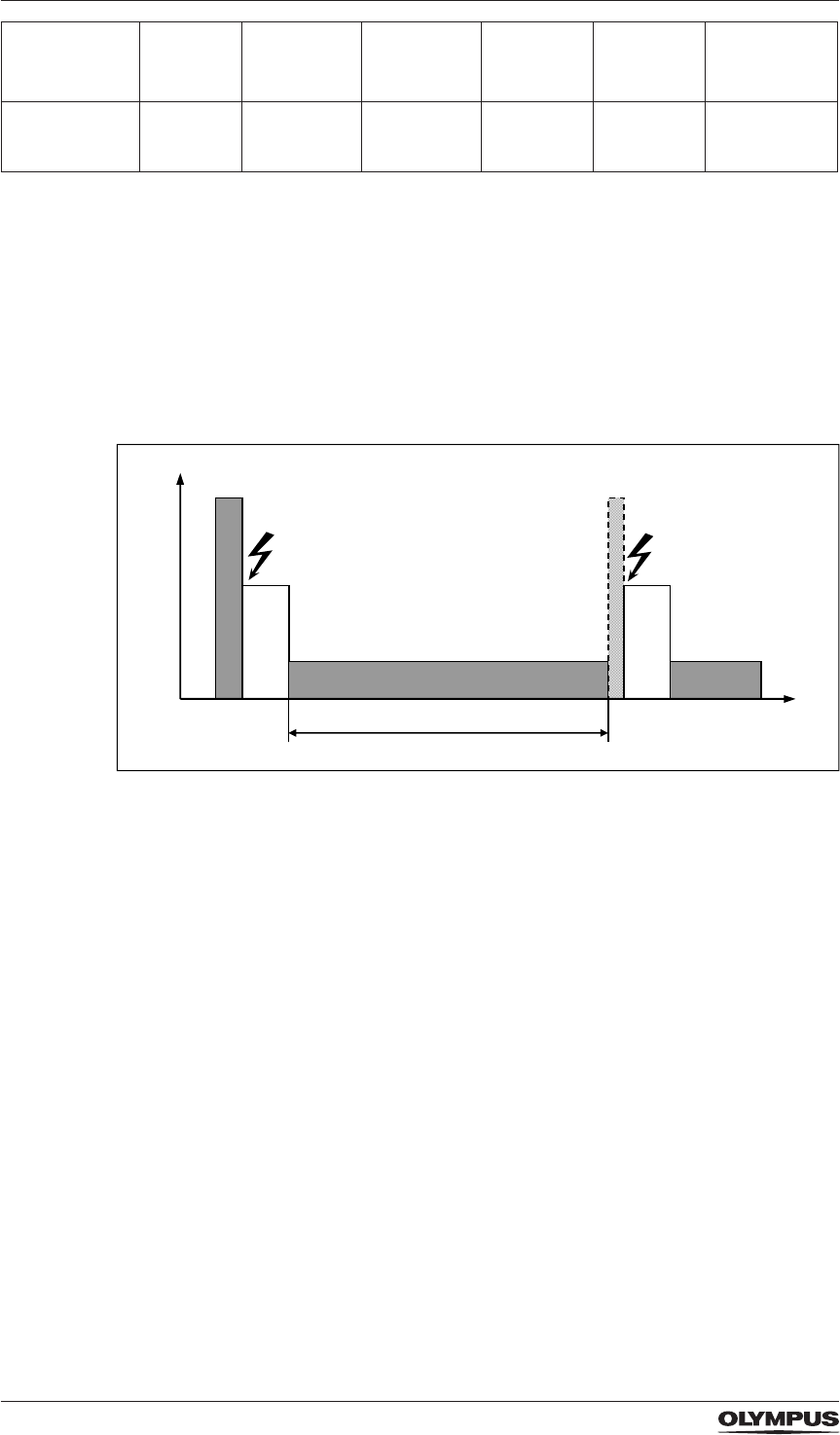
102
Appendix B
Mode Default
power
setting
Minimum
power
level1)
Maximum
power
level1)
Maximum
output
voltage
Rated
load
End-of-
procedure
load
Strong RFITT
+ RCAP
20 1 W 40 W 260 Vp100 Ω 900 Ω
Mode characteristics for monopolar modes
1) The power level is the continuous power (Watts) which can be applied during the
activation of the electrosurgical generator. The actual applied power depends on the
tissue characteristics, e.g. resistance.
Characteristics of High Power Cut Support (HPCS)
The following is an example of the characteristics of HPCS during PulseCut mode:
Characteristics of HPCS
P
HPCS
CUT
COAG
t
1
Spark Spark
time
DRAFT – 2017-01-17
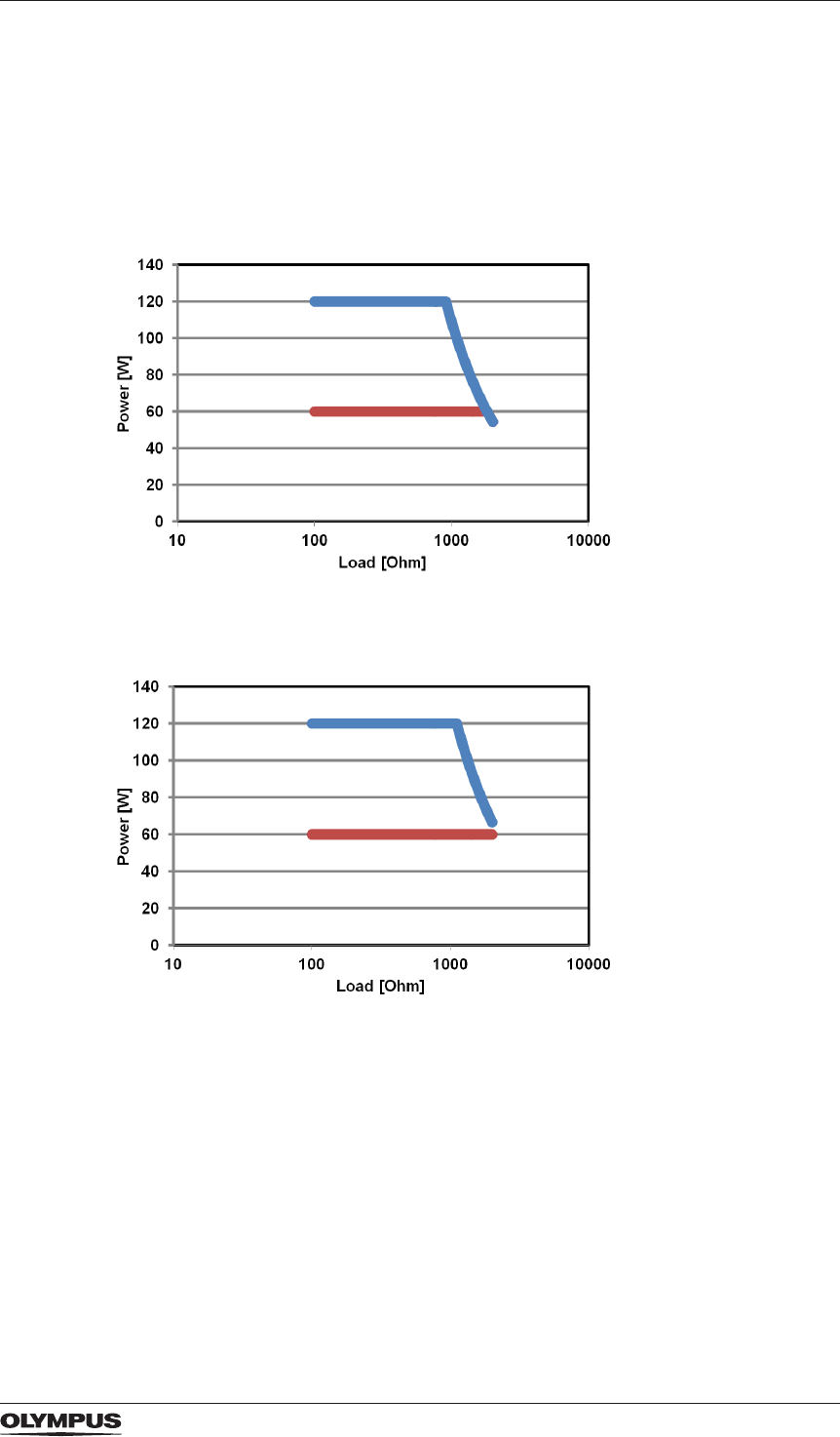
103
Appendix B
Output characteristics
The following diagrams show the output power data for each mode.
- The blue graphs indicate the data for a full output power setting.
- The red graphs indicate the data for a half output power setting.
Output characteristics of monopolar modes
FineCut
PureCut
DRAFT – 2017-01-17
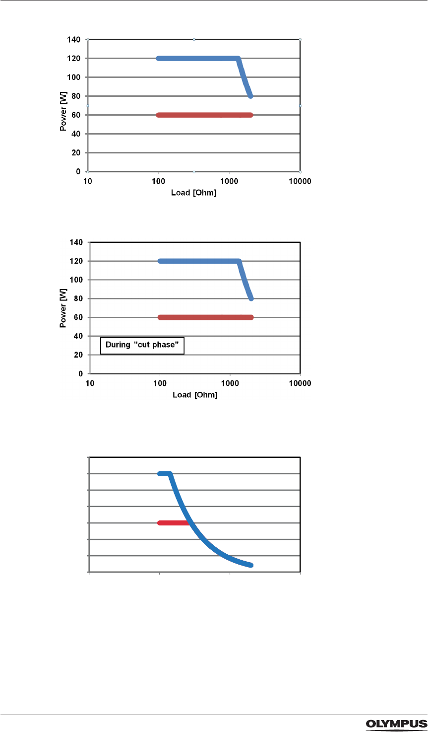
104
Appendix B
StrongCut
PulseCut
SoftCoag
0
20
40
60
80
100
120
140
10 100100010000
Power [W]
Load [Ohm]
DRAFT – 2017-01-17
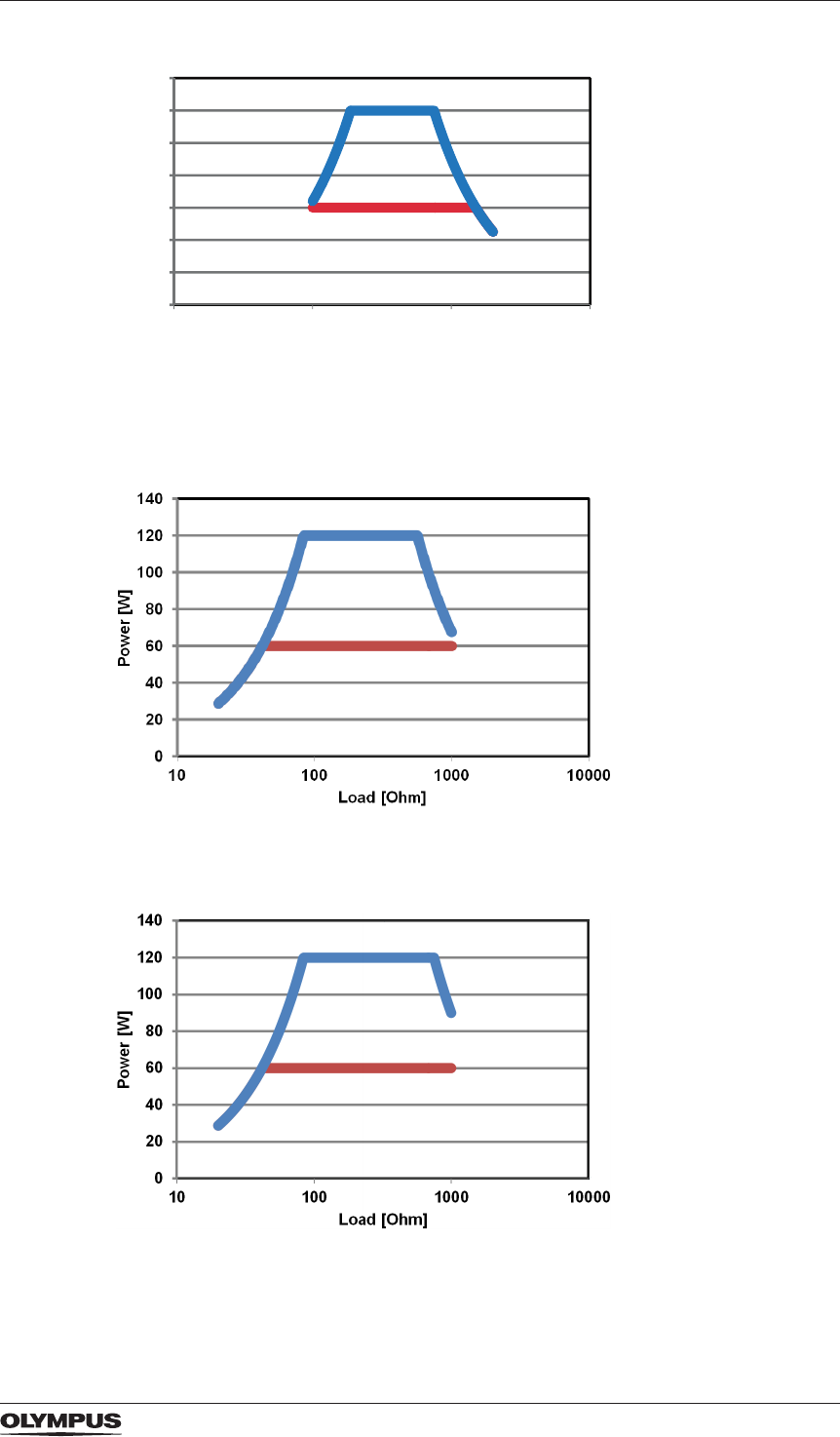
105
Appendix B
ForcedCoag
Output characteristics of bipolar modes
FineCut
PureCut
0
20
40
60
80
100
120
140
10 10010001000
0
Power [W]
Load [Ohm]
DRAFT – 2017-01-17
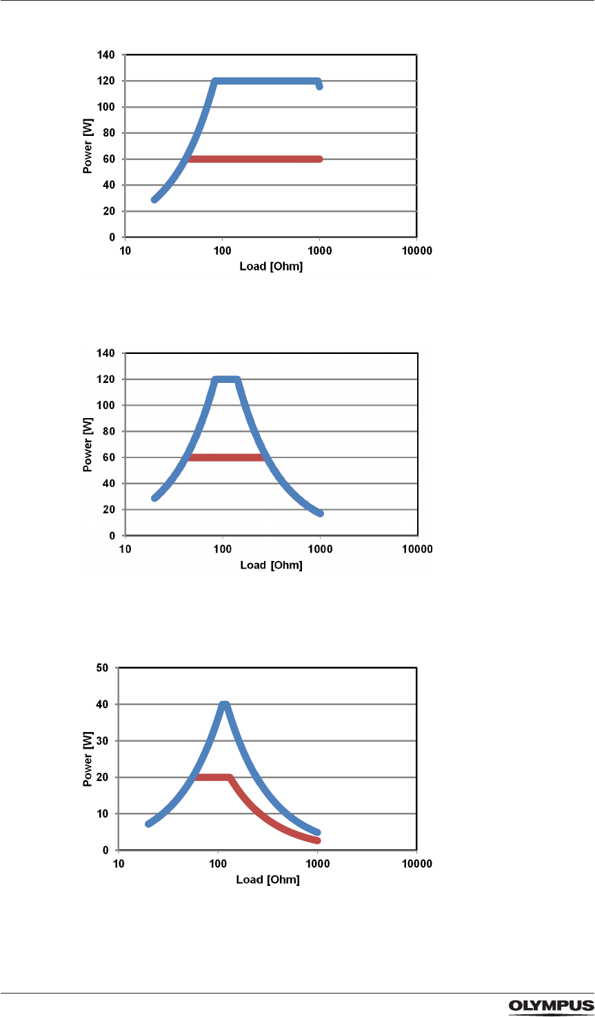
106
Appendix B
StrongCut
SoftCoag
Pure RFITT
DRAFT – 2017-01-17
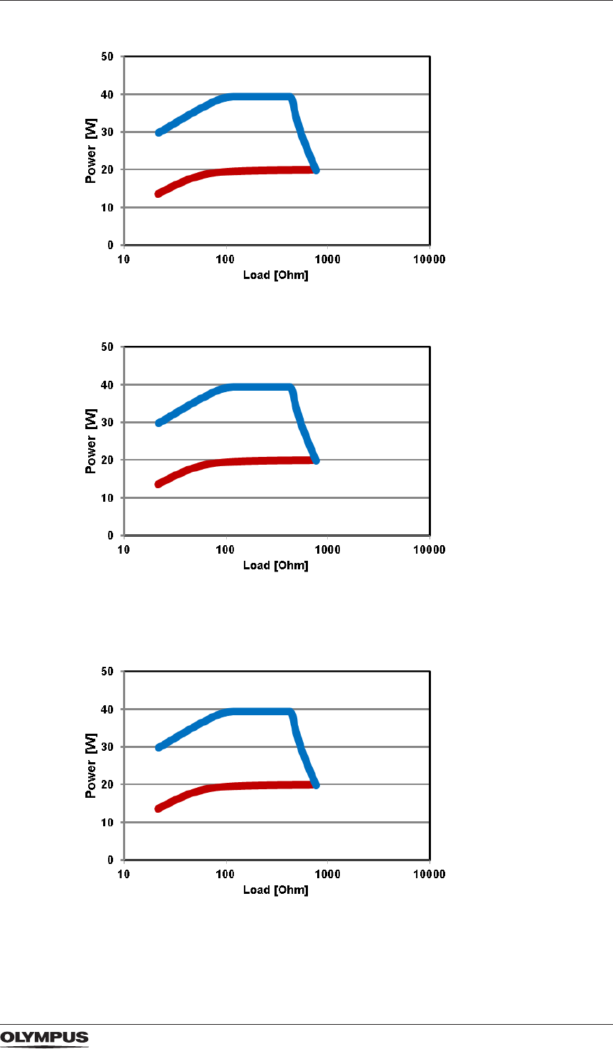
107
Appendix B
Fine RFITT
Strong RFITT
Strong RFITT + RCAP
DRAFT – 2017-01-17
DRAFT – 2017-01-17
DRAFT – 2017-01-17

W7093251_01
2016-09-30
en(US) © Copyright 2016 Olympus Winter & Ibe GmbH
DRAFT – 2017-01-17