User Manual

Part Number - I317719
US - Issue 1
© Omitec 2008
OmiScan Gas
Operating Instructions
Part Number - I317719
US
Issue 1
© Omitec 2008

Contents
iii
Introduction
Introduction............................................................................................. 5
Power Management ............................................................................... 7
Safety Precautions ................................................................................. 7
Electrical Safety Precautions.................................................................. 7
Assembling the OmiScan Gas Analyzer................................................. 8
Safe Removal and Disposal of Batteries ................................................ 9
OmiScan Gas Sample Probe ............................................................... 10
Getting Started
Emissions Testing ................................................................................ 11
Handset Navigation .............................................................................. 11
Gas Analyzer ........................................................................................ 12
Simulated Tests.................................................................................... 23
System Checks..................................................................................... 35
PC/USB Mode ...................................................................................... 37
Settings................................................................................................. 37
Low Battery Indication .......................................................................... 43
Out of Range ........................................................................................ 44
PC Gas Analyzer Software
System requirements............................................................................ 46
Installation ............................................................................................ 46
Using the Software ............................................................................... 46
Analyzer Software Functions ................................................................ 47
Communications................................................................................... 68
Software Build ...................................................................................... 68
Gas Analysis
OmiScan Gas Analysis of Results........................................................ 69

Contents
iv
Routine Maintenance & Cleaning
Routine Maintenance............................................................................ 74
NOx Cell Replacement ......................................................................... 76
Calibration and Accuracy Checks......................................................... 77
Cleaning ............................................................................................... 77
Technical Specification
Technical Specification......................................................................... 78
General Data ........................................................................................ 80
Ancillary Equipment.............................................................................. 81
Pneumatic Specifications ..................................................................... 81
Service and calibration frequency ........................................................ 82
Country Specific Approvals .................................................................. 82
Spare Parts List .................................................................................... 84
Introduction
5
Introduction
Introduction
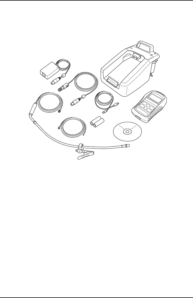
OmiScan Gas is an exhaust gas analyzer for spark ignition vehicles and comprises a
fully portable handset with a base station and optional software to install on a PC.
1. Handset
2. Base unit
3. Exhaust Probe attachment
4. Base unit exhaust pipe extension
5. Mains power converter supply
6. CD ROM with PC software
7. Vehicle power supply cable (optional)
8. USB cable handset to laptop
9. Filters
Spark ignition vehicles includes both catalyst and non-catalyst, supercharged
(including Turbo) and lean-burn engines, vehicles that are fuelled by Petrol, Liquid
Petroleum Gas (LPG) and Compressed Natural Gas (CNG) and also injection or
carburettor fuel control.
NOTE: Diesel engined vehicles are specifically excluded from testing using the
OmiScan Gas system.
7
8
1
2
3
OM1375
4
5
6
9

Introduction
6
There are two options available:
1. OM4720/5G
•Measures 5 gases, provides live readings of all gases and λ
•PC software to graph and/or diagnose emissions faults from gas readings
2. OM4720/4G
•Measures 4 gases, provides live readings of all gases and λ
•PC software to graph gas readings
The OmiScan Gas system enables the measurement of four or five of the main
exhaust gases emitted from a spark ignition engine. The gases measured are:
Carbon Dioxide (CO2), Carbon Monoxide (CO), Hydrocarbons (HC), Oxygen (O2) and
Nitric Oxide (NOx) (optional). Measurement accuracy meets or exceeds requirements
for OIML Class 0 and BAR97:
•CO:Range - 0% to 15%; accuracy typically 3% relative
•CO2: Range - 0% to 20%; accuracy typically 3% relative
•O2: Range 0% to 25%; accuracy typically 1% relative
•HC n-hexane: 0 to 2000ppm; accuracy typically 3%
•HC n-propane: 0 to 30000ppm; accuracy typically 5%
•NOx :Range - 0 to 5000ppm, accuracy typically 3% relative (optional)
The optional PC based system provides enhanced facilities for data capture and
graphing as an additional feature.
The OmiScan Gas handset communicates with the base station using Bluetooth®
Wireless Technology and with the PC option, the handset communicates with a PC
via a USB port.

Introduction
7
Power Management
The handset monitors both itself and the base station for the charge status of the
battery packs. If either battery pack voltage falls below a predetermined level the
handset will display a warning to cease testing and recharge the units. Approximately
five minutes before the batteries reach the automatic shutdown point, a message is
flagged to warn you of the low battery state and thus the imminent shutdown.
1. Low Base Station Battery
•Indicated by the handset battery symbol flashing ‘empty’ and the green LED
on the base station flashing
2. Low Handset Battery
•Indicated only by the battery symbol on handset display flashing empty.
NOTE: Once the units have been put on charge, both LED and battery symbol will
stop flashing.
Safety Precautions
WARNING: Exhaust gases are poisonous and contain carbon monoxide,
which can cause unconsciousness and can be fatal - NEVER start or leave
the test vehicle engine running in an unventilated area.
WARNING: DO NOT handle the OmiScan Gas exhaust probe tip, or place
the exhaust probe on plastic or combustible surfaces after the test
procedure. The probe may become extremely hot during the test and could
cause burns and a risk of fire.
Electrical Safety Precautions
WARNING: Any power or extension cord must have a ground conductor.
WARNING: When replacing fuses make sure the correct type and rating
are used.
WARNING: Any adjustment, maintenance or repair must be carried out by
an approved service engineer.

Introduction
8
Assembling the OmiScan Gas Analyzer
Unpack the units carefully, checking off each item and component against the
itemized packaging list included. If any component is missing or damaged, contact
your supplier immediately.
•The batteries in the base unit and the handset will need to be installed and charged
before either unit can be used (see ‘Power Management’, page 7).
•The base station battery compartment is on the underside of the unit, secured by
two cross-headed bolts. Unscrew the cover, and secure the bigger battery pack
into the cover tray with the velcro strap; connect the in-line connector to the base
station. Refit the cover and tighten the two screws (do not over tighten).
•Remove the handset rubber protection cover to access the underside of the case
cover; remove the four cross-headed screws and place to one side. Lift off the
bottom cover and place to one side. Connect the smaller of the battery packs to
the in-line connector and place the battery pack in the recess through the PCB;
taking care to keep the supply cables from catching the cover. Position the cover
and replace the four screws (do not over tighten). Refit rubber protection cover.
•Place the handset in the base station ensuring that it is pushed firmly into place
and clips into the bottom securing clip.
IMPORTANT: BATTERY PACKS SHOULD ALWAYS BE FITTED BEFORE THE
CHARGER UNIT IS CONNECTED.
•Connect the mains charging unit into the round connector at the rear of the base
station and the mains plug into a wall socket. With the mains switched on, the
middle red LED on the top surface of the base station should illuminate to indicate
that the base station is charging. The handset display will switch ON automatically
and the battery symbol in the top right hand corner will indicate progressive
charging.
•If applicable, while the batteries are charging, install the Analyzer software onto
your PC (see ‘Installation’, page 46).
•When fully charged the red base station LED will extinguish and the lower amber
LED will illuminate to indicate the base station battery is on trickle charge until the
charging unit is disconnected. Likewise, the battery symbol on the handset will
remain static showing a fully charged battery, which will be on trickle charge until
mains charging unit is disconnected.

Introduction
9
CAUTION: Before connecting the base station to the mains, ensure that
you have read and fully understand the operating instructions given in
this document.
•Attach the exhaust sample probe to the water trap fitting (2) at the rear of the base
station.
•Attach the exhaust outlet pipe to the Exhaust Gas outlet (4). The exhaust outlet
pipe is used to expel the sampled exhaust gases from the test vehicle well away
from the active working area, to prevent technicians inadvertently inhaling the
gases. Run the outlet pipe to a well ventilated area.
Safe Removal and Disposal of Batteries
Both the Base station and the handset use rechargeable
Nickel Metal Hydride battery packs. The expected working
life for each pack should be in excess of 18 months. Both
packs are consumable spare parts and are designed to be
replaced by the user. See ‘Assembling the OmiScan Gas
Analyzer’, page 8 to see how to access the batteries.
CAUTION: Ensure both Handset and Base station are
powered OFF and disconnected from charger Power
supply BEFORE replacing battery packs!
The Handset also contains a Lithium button cell for time and
date back up. This battery’s life expectancy is in excess of
5 years. This battery should not be replaced by the user.
This should be carried out by an Omitec Inc. authorized
Service Agent.
CAUTION: DO NOT DISPOSE OF BATTERIES IN
HOUSEHOLD REFUGE. SOME COMMUNITIES OFFER
RECYCLING OR THE COLLECTION OF USED
BATTERIES. CONTACT YOUR LOCAL GOVERNMENT
FOR DISPOSAL PRACTICES IN YOUR AREA.
Ni-MH
LI-ION

Introduction
10
OmiScan Gas Sample Probe
WARNING: Before attaching any OmiScan Gas probe to the test vehicle,
ensure that you have read and understand the safety precautions listed
earlier in this manual.
Exhaust probe
The exhaust probe collects gas samples from the test vehicle exhaust, which are then
analyzed by OmiScan Gas.
The probe connects between the Sample Gas Input fitting (item 2 under ‘Assembling
the OmiScan Gas Analyzer’, page 8) and the test vehicle exhaust pipe. Insert the
probe as far into the vehicle exhaust as possible and secure by attaching the alligator
clip to the end of the exhaust pipe.
WARNING: Take care to avoid contact with the exhaust system when
inserting or removing the exhaust probe. The exhaust system will be hot
and severe burns could occur.
The exhaust probe is supplied with a sealing cap (Part No. OM 4700/23) which must
be fitted over the end of the probe when a leak test is performed. Keep the cap in a
safe place when not in use (see ‘System Checks’, page 35, for further details of a leak
test).

Getting Started
11
Getting Started
Emissions Testing
Before attempting to test vehicle emissions levels, ensure that the base station and
handset are fully charged (see ‘Power Management’, page 7) for remote operation.
For on-road testing if the base station batteries are low, connect the base station to
the vehicle supply cable (optional). With this configuration the batteries will not charge
but the supply to the base station is maintained.
OmiScan Gas emissions testing can be undertaken by using the handset separated
from, or in position on, the base station.
Handset Navigation
Press the ‘Power up’ buttons on the base station and then on the handset, the
handset screen displays the ‘Main Menu’ and lists the functions available:
•Gas Analyzer
•PC/USB Mode
•Settings
•Language
The handset will automatically start searching for the Bluetooth® Wireless
Technology address specific to the base station. The handset and the base station
are ‘paired’ together to prevent any interference or acquisition from other Bluetooth®
Wireless Technology devices such as laptop PCs or mobile telephones. After a few
seconds an antenna icon will appear in the top LH corner of the screen indicating that
the Bluetooth® Wireless Technology link has been established. This icon will always
be displayed whilst the link is made.
The battery icon in the top RH corner reflects the charge status of the handset battery
pack.
NOTE: The battery icon will flash empty to indicate a low battery charge for either the
handset or the base station - see ‘Power Management’, page 7.
The Main Menu has four options:
•Gas Analyzer - Emission testing and analyzer system checks
•PC/USB Mode - Used for down loading test result and updating handset
MAIN MENU
Gas Analyzer
PC/USB Mode
Settings
Lang, Idioma
Getting Started
12
•Settings - Results record, clock and general system settings
•Language - Allows the user to configure handset in English, French or Spanish
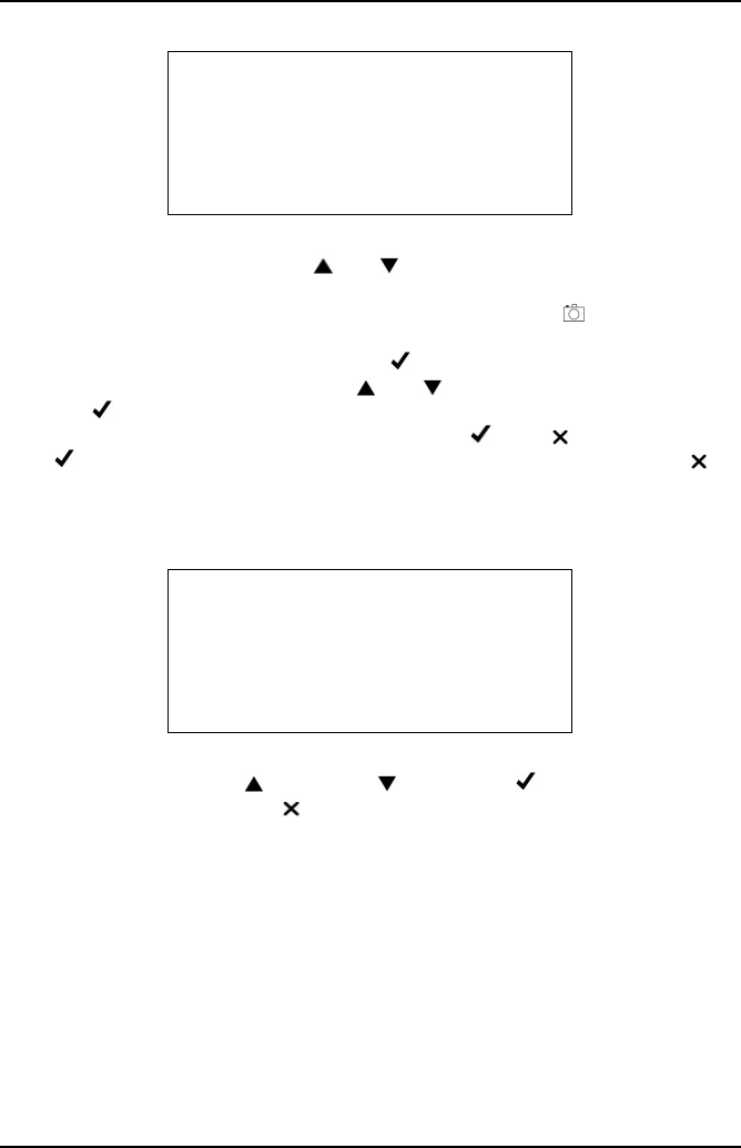
Gas Analyzer
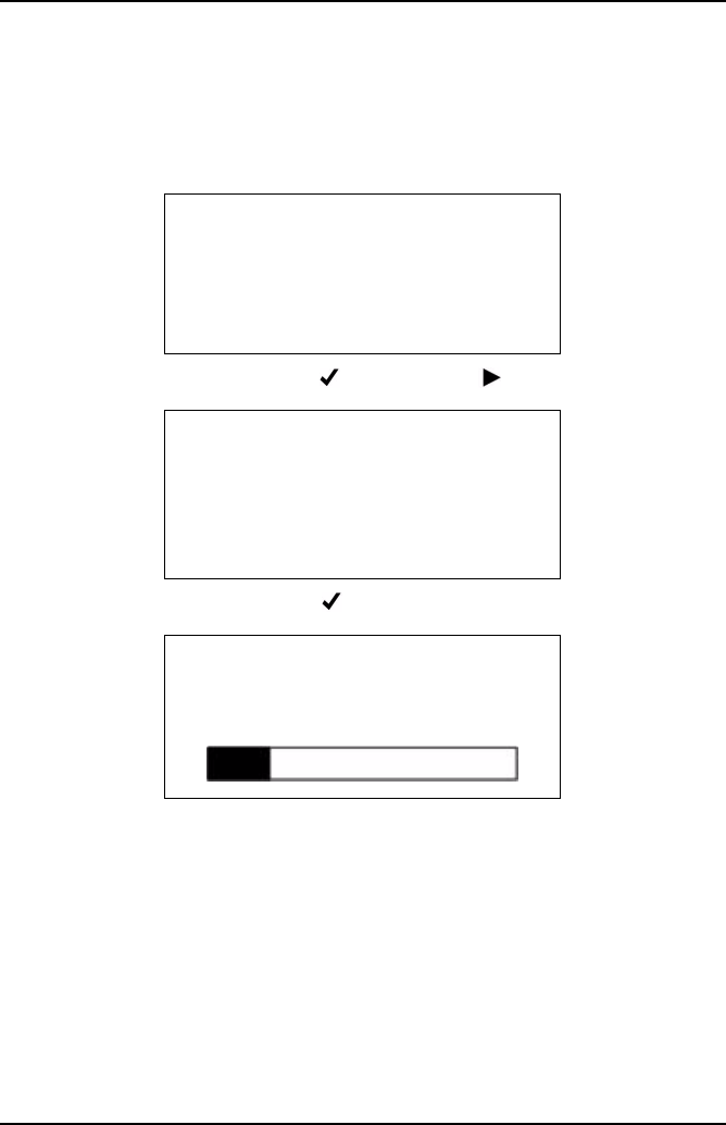
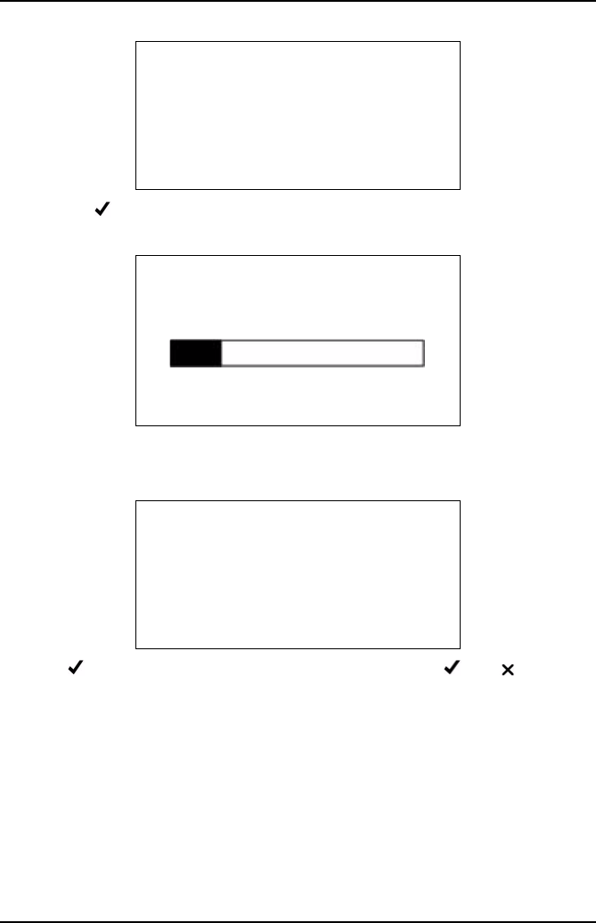
To access Emission Menu press the button with the pointing at Gas Analyzer.
Follow the instructions and press the button.
The handset will display ‘Analyzer SetUp - Please Wait’ and a progress bar. On
completion the progress bar will be replaced briefly by ‘Passed’.
During this time the analyzer is initializing settings ready to conduct emissions testing.
Once completed the display screen will change back to the ‘Main Menu’.
The handset has an automatic power saving facility, if no action is taken after one
minute the display backlight powers down. Pressing any button will turn the backlight
back on. If the handset does not detect a button press for more than 15 minutes it will
assume that the OmiScan Gas is not in use and the Base Station and the Handset
will automatically power down.
NOTE: The automatic shutdown feature is disabled during ‘Live Reading’ test.
MAIN MENU
Gas Analyzer
PC/USB Mode
Settings
Lang, Idioma
REMOVE THE PROBE
Ensure the exhaust
probe is in clean
air
-OK
ANALYZER SETUP
Please wait. . . . .

Getting Started
13
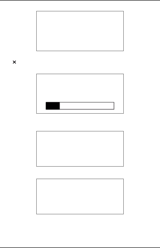
Manual Power Down
To power down both Handset and Base station at the same time, simply press and
hold power button on handset for >1 second.
Live Readings
Press the again to enter the ‘Gas Analyzer’ menu and again to start ‘Live
Readings’.
The screen momentarily displays ‘Live Readings’, then ‘Please wait’ then asks the
technician to ‘Repeat’ or ‘Restart’ a test, displaying the vehicle data from the last
test: Manufacturer, Licence plate, year and fuel type.
NOTE: When using for the first time, there will not be any previous tests stored,
therefore the handset will proceed directly to the series of screen reminders before
starting a test.
For ‘Repeat’ see page 18, ‘Restart’ sequence follows.
Other fuels offered are:
•Ethanol E85
•Methanol M85
GAS ANALYZER
Live Readings
Simulated Tests
System Checks
SAME VEHICLE?
FORD
OU54XYZ***
2006 Gasoline
-Repeat X-Restart
SELECT FUEL TYPE
Gasoline
USA Reformulated
LPG
CNG

Getting Started
14
•Gasohol E10
•Gasohol E20
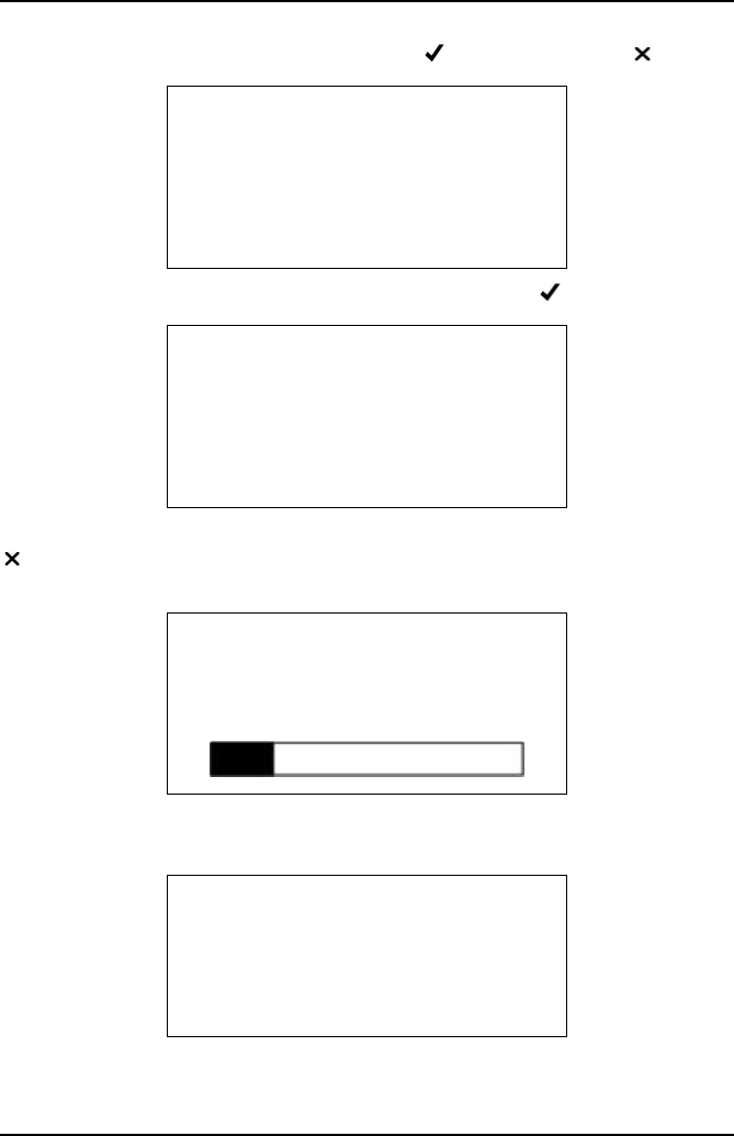
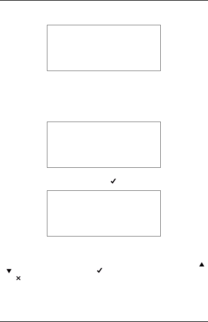
Pressing Restart will display a screen asking for fuel type.
The remaining memory will be shown. On pressing -OK the series of screens and
procedures will be displayed.
A series of screen reminders are displayed: ‘Ensure oil and coolant levels OK’, press
to continue, or press to abort’.
‘Ensure brake on and in neutral/park, press to continue, or press to abort’.
LIVE READINGS
Remaining Memory:
56Mins 40secs
-OK X-Cancel
LIVE READINGS
Ensure oil and
coolant levels OK
-Continue X-Abort
LIVE READINGS
Ensure brake on and
in neutral/park
-Continue X-Abort
LIVE READINGS
Ensure engine is
running and up to
temp.
-Continue X-Abort
Getting Started
15
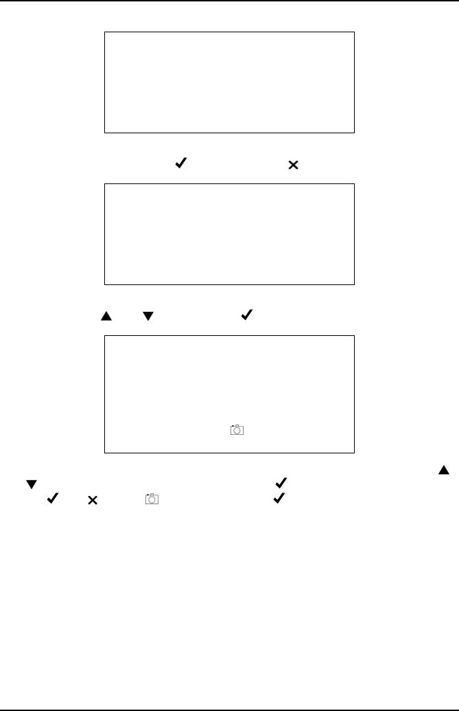
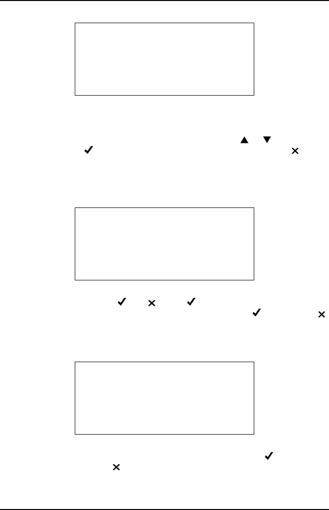
‘Ensure engine is running and up to temp., press to continue, or press to abort’.
‘HC HANGUP Ensure the exhaust probe is in clean air, press to continue.
HC HANGUP’ ‘HC residue check’, ‘Please wait’, Lim: 20ppm HC: XX’, ‘XXsecs’, press
- to abort. On completion of the countdown the screen will briefly display ‘HC
residue check passed.’
The base station will automatically carry out a ZERO CALIBRATION, on completion
the progress bar will be replaced briefly by ‘Passed’.
On completion there is a prompt to ‘INSERT PROBE’.
HC HANGUP
Ensure the exhaust
probe is in clean
air
-OK
HC HANGUP
HC residue check
Please wait . . . .
Limit: 20ppm HC: 00
9 secs X-Abort
X
ZERO CALIBRATION
Please wait . . .
INSERT PROBE
Exhaust probe check.
Please wait . . . .
-Continue X-Abort
X

Getting Started
16
As soon as gas is sensed there is a request for the number of gases to display, all,
two or one and also an ‘Exit Test’.
If ‘1 Gas Display’ or ‘2 Gas Display’ is selected, an additional menu will be displayed
listing the gases or outputs that can be displayed, which are CO, HC, O2, CO2,
Lambda, NOx, Air Fuel Ratio (AFR) and corrected CO (COK).
To make a selection, scroll up or down and press . In ‘2 Gas Display’ option, the
selection will be tagged with an arrow. To deselect press again. Once the second
gas has been selected, the handset will exit the menu and display the selected gases.
On selection the screen will display the gas and the gas level in % or ppm, as
appropriate.
There is no fixed time for this test, however, there is a prompt to ‘Start’ and ‘Stop’
using the button. When sampling, a ‘Mark’ can be made at a specific point in the
test by pressing the button. This will set a marker in the data that is displayed in
the analyzer data graph on the PC.
LIVE READINGS
Display All.
2 Gas Display
1 Gas Display
Exit Test
X
LIVE READINGS
HC: 0 λ: 0.00
CO: 0.001% CO2: 0.00%
O2: 21.02% NOx: 0ppm
-Start X-Go back X
LIVE READINGS
HC: 0 λ: 0.00
CO: 0.001% CO2: 0.00%
O2: 21.02% NOx: 0ppm
-Stop -Mark X-Go back X
Getting Started
17
When stop is pressed the screen displays ‘Test Result XX’ ‘Live Readings’ ‘Time:
XX:XX’ ‘Date: XX/XX/XX’ press to save, or press to erase.
If saving, the next screen displays ‘SELECT MAKE’ and makes of vehicles can be
scrolled using the and buttons. Press to select the make.
The next screen displays ‘ENTER VEHICLE YEAR’, 200X (model year) and the
and buttons will scroll through the years, press to select the year, the bottom
line, i.e. -OK -Cancel -Move will flash until is pressed to confirm.
TEST RESULTS 1
Live Readings
Time: 09:11
Date: Feb 20 08
-Save X-Erase X
SELECT MAKE
Not recorded
ACURA
ALFA ROMERO
ASTON MARTIN
LIVE READINGS
Enter Vehicle Year
200X
-OK X-Cancel - Move

Getting Started
18
The next screen displays ‘LIVE READINGS’ ‘Vehicle License No:’ ‘XXXXXXXXXX’.
The and buttons will set each character from A to Z and 0 to 9, when the first
character is correct press the camera button. Move to the next character and
repeat the procedure until the registration number has been added press . The
bottom line, i.e. -OK -Cancel -Move will flash until is pressed again to
confirm.
Next screen displays ‘SELECT TYPE’ and a list of vehicle type, eg. Hatchback,
Sedan, Station wagon, Convertible, Coupe and 4x4.
The next screen displays ‘TESTER NAME’ and a list of stored testers, a default list
shows ‘Tester 1’, ‘Tester 2’ etc.
On selection of the tester the remaining memory is displayed.
LIVE READINGS
Vehicle License No:
**********
----------
-OK X-Cancel - Move
SELECT TYPE
Not recorded
Sedan
Coupe
Convertible
TESTER NAME
Not recorded
TESTER 1
TESTER 2
TESTER 3
TESTER 4
LIVE READINGS
Remaining Memory:
61Mins 43secs
-OK X-Cancel
Getting Started
19
Pressing the -OK will start a ‘System Purge’ procedure to remove any residual
exhaust gases in the probe and pipework.
On completion of the ‘System Purge’ the display will return to the Gas Analyzer menu.
If pressing ‘Repeat’ the following sequence will occur:
Pressing will display ‘Remaining memory: XXMins XXsecs’ -OK, -Cancel. If
there is insufficient time available to complete another test the handset will need to
have the existing files deleted (see ‘Settings’, page 37). For ‘Restart’ see page 13.
NOTE: If you have the PC option, make sure that any tests you wish to keep/analyze
are down loaded to the PC before deleting the files.
REMOVE THE PROBE
Please Wait. . .
-OK X-Cancel
SYSTEM PURGE
Please wait . . .
X-Cancel
X
LIVE READINGS
Remaining Memory:
61Mins 43secs
-OK X-Cancel

Getting Started
20
A series of screen reminders are displayed: ‘Ensure oil and coolant levels OK’, press
to continue, or press to abort’.
‘Ensure brake on and in neutral/park, press to continue, or press to abort’.
‘Ensure engine is running and up to temp., press to continue, or press to abort’.
‘HC HANGUP Ensure the exhaust probe is in clean air, press to continue.
LIVE READINGS
Ensure oil and
coolant levels OK
-Continue X-Abort
LIVE READINGS
Ensure brake on and
in neutral/park
-Continue X-Abort
LIVE READINGS
Ensure engine is
running and up to
temp.
-Continue X-Abort
HC HANGUP
Ensure the exhaust
probe is in clean
air
-OK
Getting Started
21
HC HANGUP’ ‘HC residue check’, ‘Please wait’, Limit: 20ppm HC: XX’, ‘XXsecs’,
press - to abort. On completion the screen will briefly display ‘HC residue check
passed.’
The base station will automatically carry out a ZERO CALIBRATION, on completion
the progress bar will be replaced briefly by ‘Passed’.
On completion there is a prompt to ‘INSERT PROBE’.
As soon as a gas is sensed there is a request for the number of gases to display, all,
two or one and also an ‘Exit Test’.
HC HANGUP
HC residue check
Please wait . . . .
Limit: 20ppm HC: 00
9 secs X-Abort
X
ZERO CALIBRATION
Please wait . . .
INSERT PROBE
Exhaust probe check.
Please wait . . . .
-Continue X-Abort
X
LIVE READINGS
Display All.
2 Gas Display
1 Gas Display
Exit Test
X

Getting Started
22
If ‘1 Gas Display’ or ‘2 Gas Display’ is selected, an additional menu will be displayed
listing the gases and outputs that can be displayed, which are CO, HC, O2, CO2,
Lambda, NOx, Air Fuel Ratio (AFR) and corrected CO (COK).
To make a selection, scroll up or down and press . In ‘2 Gas Display’ option, the
selection will be tagged with an arrow. To deselect press again. Once the second
gas has been selected, the handset will exit the menu and display the selected gases.
On selection the screen will display the gas and the gas level in % or ppm, as
appropriate.
There is no fixed time for this test, however, there is a prompt to ‘Start’ and ‘Stop’
using the button. When sampling, a ‘Mark’ can be made at a specific point in the
test by pressing the button. This will set a marker in the data that is displayed in
the analyzer data graph on the PC.
When stop is pressed the screen displays ‘Test Result XX’ ‘Live Readings’ ‘Time:
XX:XX’ ‘Date: XX/XX/XX’ press to save, or press to erase.
LIVE READINGS
HC: 0 λ: 0.00
CO: 0.001% CO2: 0.00%
O2: 21.02% NOx: 0ppm
-Start X-Go back X
LIVE READINGS
HC: 0 λ: 0.00
CO: 0.001% CO2: 0.00%
O2: 21.02% NOx: 0ppm
-Stop -Mark X-Go back X
TEST RESULTS 1
Live Readings
Time: 09:11
Date: Feb 20 08
-Save X-Erase X

Getting Started
23
Pressing -Save will store the results and the screen will change to live readings
available memory. Pressing -OK will display the Gas Analyzer menu, after the
‘remove probe’ and system purge’ screens.
Simulated Tests
Simulated tests has three test procedures:
•CAT
•TSI
•ASM
Note: The 4 Gas version of OmiScan Gas only offers TSI as NOx is not fitted. CAT
and ASM require NOx readings.
LIVE READINGS
Remaining Memory:
56Mins 40secs
-OK X-Cancel
GAS ANALYZER
Live Readings
Simulated Tests
System Checks
SIMULATED TESTS
CAT
TSI
ASM

Getting Started
24
CAT
In this test all five gases HC, CO, CO2, NOx and O2 are analyzed to gauge the
performance of a Catalytic convertor. The test will report that the Catalytic convertor
is good, suspect or if the gas readings suggest there may be another fault which may
not be related to the Catalytic convertor (only available for 5-gas option).
Selecting petrol will start a sequence of screens, remaining memory, oil and coolant
levels, hand brake and engine running and up to temperature. HC Hangup sequence
will be started ending with a Zero Calibration and a prompt to insert probe into the
exhaust pipe. The process will continue with fast idle.
Open the throttle to increase engine speed to within the indicated RPM range.
CAT
Please Wait. . . .
SELECT FUEL TYPE
Gasoline
USA Reformulated
LPG
CNG
CAT
Run engine between
2500 - 3000 RPM
-OK X-Abort

Getting Started
25
A short preconditioning before continuing the fast idle test.
If the gas level is within the limits the test will be complete and a report of ‘Within
Limits’ will be displayed.
If the test fails an extended test can be started.
The additioning conditioning comprises an extended period at fast idle to ensure that
the catalyzer is at the correct temperature to start and maintain the catalytic reaction.
CAT
Preconditioning
5 secs
X-Abort
X
CAT
Fast Idle Test
30 secs
X-Abort
X
CAT
Outside Limits
X = Quit
= Extended test
or X
CAT TEST
Additional
conditioning
Fast Idle test?
-Continue X-Abort
or X

Getting Started
26
The vehicle engine speed must be set to within the range indicated.
If the cat fails again a results page is displayed.
The test results can be saved or erased as required.
CAT
Run engine betweeen
2500-3000 RPM
-OK X-Abort
CAT
Fast Idle Test
180 secs
X-Abort
X
NON-CAT FAULT
CO = -0.00%, HC = 0ppm
O2 = 20.97%, CO2 = 0.00%
NOx = 0ppm
-OK

Getting Started
27
TSI Test
This test simulates the ‘first chance’ IDLE and HIGH SPEED modes outlined in the
EPA91 Two Speed Idle emissions test. The test is designed to allow the user to
evaluate how a vehicle may perform when tested officially.
Note: This is not an official test.
A warning screen displays the fact that this test routine is not an official test and can
be used only as a guide to see if gas levels pass/fail the preset gas limits.
The option to carry out the test on the last vehicle tested or a new vehicle will be
offered. If a new vehicle is selected, you will be prompted for fuel type at the start of
the test, so that the correct parameters can be set. At the end of the test, before
saving the results you will be prompted for vehicle make, year etc. If the test is being
carried out on the last vehicle tested then fuel type, vehicle make and year etc. will
have already been saved by the handset and will be automatically added to the test
result if it is chosen to be saved.
WARNING!
This is NOT
an official
TSI test
-OK, X-Cancel
X or
SAME VEHICLE?
CITROEN
OU54XYZ***
2006 Gasoline
-Repeat, X-Restart

Getting Started
28
The test limits to be applied can be selected from the next menu screen. Simply scroll
down and press to select. Note TSI (Custom 1) and TSI (Custom 2) limits can be
edited to suit testing requirements using PC Gas Analyzer Software – see ‘Tests’,
page 61‘ detailed in the PC Analyzer Software section of this manual.
Test limits are displayed. Press to proceed or X to go back to Limit Menu screen
to select other limits.
Remaining memory screen will be displayed. Note the TSI can require up to
approximately 3 minutes to complete.
The handset will then detail the same preconditioning, HC hang, Zero Calibration and
Insert Probe Screens as in other test routines before displaying:
TEST LIMITS
TSI (Default)
TSI (Custom 1)
TSI (Custom 2)
TEST LIMITS
HC = 200ppm
CO = 1.00%
-OK, X-Cancel
TSI
Remaining Memory:
59 mins 44 secs
-OK, X-Cancel
X or

Getting Started
29
Press to Start test.
The test readings will be displayed along with a test countdown. Maximum duration
of test mode is 90 seconds.
At the end of the IDLE Mode test the result will be displayed. Press to proceed to
the HIGH Speed Mode part of the test.
Screen prompts for the vehicle idle speed to be raised and maintained between an
upper and lower limit for the duration of the HIGH Speed Mode of the test. Press
to proceed.
TSI TEST
ALLOW VEHICLE SPEED TO IDLE
BETWEEN 350 - 1100 RPM
-OK, X-ABORT
IDLE MODE
HC (200) = 54ppm
CO (1.00) = 0.05%
77 Secs X-ABORT
WITHIN LIMITS
HC (200) = 54ppm
CO (1.00) = 0.05%
-OK, X-ABORT
TSI TEST
RUN ENGINE BETWEEN
2200-2800 RPM
-OK, X-ABORT

Getting Started
30
The test readings will be displayed along with a test countdown. Maximum duration
of test mode is 90 seconds.
At the end of the HIGH SPEED Mode test the result will be displayed. Press to
proceed.
The overall result of the TSI test will be displayed. Press the ‘Camera’ button to see
a summary of both modes of the test. Press to proceed.
HIGH SPEED MODE
HC (200) = 54ppm
CO (1.00) = 0.05%
77 Secs X-ABORT
WITHIN LIMITS
HC (200) = 54ppm
CO (1.00) = 0.05%
-OK, X-ABORT
TSI TEST RESULT
WITHIN LIMITS
-OK, X-ABORT

Getting Started
31
Press to save or X to discard. If the test was carried out on a new vehicle the
screen will prompt for make, year etc. before returning to the Simulated Test Menu. If
the test was carried out on the last vehicle tested then the screen will revert straight
back to the Simulated Test Menu.
ASM Test
This test simulates measurement and analysis carried out during a ‘Acceleration
Simulation Mode’ Test as outlined in specification EPA420-B-04-011. The gases
measured are CO, HC and NOx. The test is designed to allow the user to evaluate
how a vehicle may perform in an official test.
Note: This is not an official test.
A warning screen displays the fact that this test routine is not an official test and can
be used only as a guide to see if gas levels pass/fail the preset gas limits.
The option to carry out the test on the last vehicle tested or a new vehicle will be
offered. If a new vehicle is selected, you will be prompted for fuel type at the start of
TEST RESULT
Default TSI
TIME: 11:45
DATE: Oct 03 08
-OK, X-Erase
WARNING!
This is NOT
An official
ASM test
-OK, X-Cancel
SAME VEHICLE?
CITROEN
OU54XYZ***
2006 Gasoline
-Repeat, X-Restart

Getting Started
32
the test, so that the correct parameters can be set. At the end of the test, before
saving the results you will be prompted for vehicle make, year etc. If the test is being
carried out on the last vehicle tested then fuel type, vehicle make and year etc. will
have already been saved by the handset and will be automatically added to the test
result if it is chosen to be saved.
The test limits to be applied can be selected from the next menu screen. Simply scroll
down and press . Note ASM (Custom 1) and ASM (Custom 2) limits can be edited
to suit testing requirements using PC Analyzer Software – see ‘Tests’, page 61‘
detailed in the PC Analyzer Software section of this manual.
Test limits are displayed. Press to proceed or X to go back to Limit Menu screen
to select other limits.
Remaining memory screen will be displayed. Note the ASM can require up to a
minute and a half to complete.
The handset will then detail the same preconditioning , HC hang , Zero Calibration as
in other test routines before displaying:
TEST LIMITS
ASM (Default)
ASM (Custom 1)
ASM (Custom 2)
TEST LIMITS
HC = 150ppm
CO = 1.50%
NOx= 1000ppm
-OK, X-Go back
DEFAULT ASM
Remaining Memory:
54mins 56 secs
-OK, X-Cancel

Getting Started
33
The test requires values for both Ambient Temperature and Relative Humidity to be
entered. These parameters are required for a Humidity correction factor which is
applied to the NOx readings. Use the Up and Down keys to alter each reading then
press enter. When both values have been entered the bottom line of the display
will flash. Either press confirm or ‘Camera’ to change value.
The Handset will then display the Insert Probe Screen before displaying screens
advising on precautions that should be taken if the ASM test is being conducted
during a road test.
WARNING – SAFETY PRE CAUTION: ANY ASM TEST
CARRIED OUT DURING A ROAD TEST SHOULD BE
CONTROLLED BY A PASSENGER AND NOT THE
DRIVER.
The handset will prompt for the vehicle to be bought to the load or speed for the test.
PLEASE ENTER
Amb. Temp. 68 F
Rel. Humidity 45%
-OK, X-Cancel ‘Camera’ - Redo
ASM TEST
If Road Test ensure
Probe is fitted
securely
-OK, X-Abort
ASM TEST
If Road Test ensure
Analyser exhaust is
vented out of vehicle
-OK, X-Abort

Getting Started
34
Press to Start test.
The test readings will be displayed along with a test countdown. Maximum duration
of test mode is 90 seconds.
At the end of the test the handset will display the result either ‘Inside Limits’ or
‘Outside Limits’. Press to enter Save Result screen.
Press to save or X to discard. If the test was carried out on a new vehicle the
screen will prompt for make, year etc. If the test was carried out on the last vehicle
tested then the result will be saved with the previous details. Once the test result has
been saved or discarded the handset will display a revised ‘Remaining Memory’
screen before offering the option to ‘Repeat Test’.
ASM TEST
Set vehicle to
Desired speed/load
-OK, X-Abort
ASM TEST
HC (150) = 75ppm
C0 (1.00) = 0.30%
NOx (1000) = 120ppm
77 Secs X: Abort
WITHIN LIMITS
HC (150) = 75ppm
C0 (1.00) = 0.30%
NOx (1000) = 120ppm
-Continue
TEST RESULT
Default ASM
TIME: 11:45
DATE: Oct 03 08
-OK, X-Erase

Getting Started
35
If the option to finish test is taken the handset will display a prompt to remove the
probe when the vehicle is stationary.
The Analyzer will automatically detect the probe being removed before conducting a
‘System purge’ then returning to ‘Gas Analyzer’ Menu.
System Checks
There are eight system checks:
•Leak Test
•Manual HC HangUp
•Display PEF
•Environmental Data
•O2 Cell Functions
•Zero Calibration
•Base Stn Battery
•Bench Data
•4/5-gas setup
WITHIN LIMITS
Repeat Test?
-OK, X-Finish
REMOVE PROBE
Ensure vehicle is
Stationary and
Parking brake on
- O K
GAS ANALYZER
Live Readings
Simulated Tests
System Checks

Getting Started
36
Leak Test - Follow on screen instruction to check integrity of water trap and probe.
Manual HC Hangup - Follow the on screen instructions to clear the system of
residual HC gas.
Display PEF - Displays the current Petrol Equivalent Factor.
Environmental Data - This function is for use by a calibration engineer and has no
user functionality.
O2 Cell Functions - There are two items:
•Oxygen Cell Value
•Displays the output sensor voltage in mV
•Renew Oxygen Cell
•This resets the cell error code and recalibrates the analyzer with the new cell
(see ‘Oxygen cell replacement procedure’, page 75)
Zero Calibration - Follow the on screen instructions to zero the measurement gases
by reading fresh air.
Base Stn Battery - Displays current base station battery level and whether or not it
is being charged 0 for off charge, >200 if on charge.
Bench Data - Provides data about the gas bench, has no user functionality.
4/5-gas setup - This indicates whether or not a NOx sensor has been fitted, which
will determine if the CAT simulated test is activated.
BENCH PEF VALUE
0.533
-OK
BENCH DATA
ID: 01 S/W Rev: X4
SerNum: 0000196
Date: Oct 12 2007
-OK
BUILD STATE
Bench is 5-Gas
(NOx cell fitted)
-OK

Getting Started
37
PC/USB Mode
Simply follow on screen instructions.
Settings
Under ‘Settings’ there are seven items:
•Manage Files
•Display Clock
•Change Contrast
•View Thresholds
•Wireless Setup
•S/W Version
•Factory Default
PC/USB MODE
Ensure USB cable is
connected to the PC
and the Handset
X-Cancel X
SETTINGS
Manage Files
Display Clock
Change Contrast
View Thresholds
X
Getting Started
38
Manage Files
There four items under Manage Files:
•Summary
•List by Date
•List by Plate
•Actions
The ‘Summary’ screen displays the number of results stored and the amount of time
left in memory, to exit from the screen press .
The ‘List by Date’ screen displays the list of stored tests by date in MM/DD/YY and
time of the test. Each result is also listed by ‘Last Test First’. Where relevant, a test
result will be listed, e.g. CAT test may list ‘CAT OK’ or ‘Suspect CAT’. The integrity of
the data saved will also be listed, e.g. if the test is cut short. To select a test use
or keys, to view the test details press - VIEW or to return to ‘Manage Files’ menu
press - GOBACK. When viewing files the following data is displayed: Date and
time (of test), Plate (License No.), Type: (live Readings, Simulated tests), Durn:
(length of test), Manuf: (vehicle manufacturer), Year (vehicle MY), Fuel: (fuel type),
Class: (sedan, station wagon, 4x4 etc.), Opr: (name of the Technician carrying out the
test).
MANAGE FILES
Summary
List by Date
List by Plate
Actions
X
STORAGE SUMMARY
2 results
Mem Left: 61m 43s
-OK
-VIEW X- GOBACK
02/05/08 10:50
01/31/08 14:20
Getting Started
39
The ‘List by Plate’ screen displays the list of stored by license plate (Registration N°).
Each result is also listed by ‘Last Test First’. Where relevant a test result will be listed,
e.g. CAT test may list ‘CAT OK’ or ‘Suspect CAT’. The integrity of the data saved will
also be listed, e.g. if the test is cut short. To select a test use or keys, to view
the test details press - VIEW or to return to ‘Manage Files’ menu press -
GOBACK. When viewing files the following data is displayed: Date and time (of test),
Plate (Registration No.), Type: (live Readings, Simulated tests), Durn: (length of test),
Manuf: (vehicle manufacturer), Year: (vehicle MY), Fuel: (fuel type), Class: (sedan,
station wagon etc.) and Opr: (name of tester).
The ‘Actions’ screen displays ‘TEST RESULTS’ and ‘Delete all’ the bottom right of the
screen will alternately display and . Press and the screen will display
‘DELETE FILE’ ‘Do you really want to delete ALL results?’. Press to delete and
to return to ‘Manage Files’ menu.
Display Clock
When you select ‘Display Clock’ the screen displays ‘DATE AND TIME’ and the day,
date, and time in hours/mins/secs. If date and time are correct, press - ‘OK’ returns
to the ‘Settings’ menu, press - ‘Set Clock‘ will allow you to change the year, month,
day and time.
-VIEW X- GOBACK
OU54XYZ***
--
TEST RESULTS
Delete all
DATE AND TIME
Mon 11/02/08 15:05:26
-OK
X-Set Clock
Getting Started
40
The screen will display ‘SETUP DATE AND TIME’, ‘YY 200X’, ‘X’ will flash to indicate
that it can be changed by using the and will increase or decrease the number.
When the next number needs to be changed, e.g. if the year is 2009 and needs to be
changed to 2010, the 9 will flash, when changed to 0, press the to move to the
preceding number to change that to 1; this procedure is used for days, hours and
minutes. When the correct year is set, press and cursor moves to ‘MM’ and ‘XXX’
will flash, month can be set by using the and buttons until the correct month is
set, press . ‘DD’, ‘Day’, ‘hh’, ‘mm’ are changed and set in the same manner. On
completion of setting ‘mm’, the bottom line containing - OK, - Cancel will flash,
press to accept the settings and return to ‘DATE AND TIME’ screen, press to
abort settings and return to ‘DATE AND TIME ‘ screen.
Change Contrast
When you select ‘Change Contrast’, the screen displays ‘CHANGE CONTRAST’ and
there are four options press to increase, to decrease, - OK to retain changes
and return to ‘Settings’ menu, or - Cancel to exit without saving changes and return
to ‘Settings’ menu.
SET DATE AND TIME
YY 200X DAY Wed
MM Feb hh 11
DD 27 mm 07
-OK, X-Cancel
CHANGE CONTRAST
Ï-Increase
Ð-Decrease
-OK
X-Cancel

Getting Started
41
View Thresholds
When you select ‘View Thresholds’ the screen will display the threshold levels of the
various gases for all of the simulated test procedures, TSI Default, Custom TSI 1,
Custom TSI 2, ASM Default, Custom ASM 1, Custom ASM 2 and CAT. Press to
toggle through thresholds one at a time.
Wireless Setup
When you select ‘Wireless Setup’ the screen will display ‘WIRELESS SETUP’ with
item:
•Base Station
In ‘Base Station’ the screen displays ‘Set base station address’, e.g.
‘008098E5CCBC’ (this address is preset on build and would not normally require
changing). The address is an alphanumerical address and ensures that the handset
talks only to that Bluetooth® Wireless Technology address. The Bluetooth® Wireless
Technology address should be written in the Quick Guide in the area provided. Use
the and/or on the handset to set each address character; when correct, press
the button to move to the next character. On completion of entering all of the
characters, press to save, the bottom line (-OK X-Cancel -Move) will flash until
is pressed again to confirm the address and exit. Press to cancel change and
exit.
CAT DEFAULT
CO<0.3% HC<200
O2<1.00% CO2>14.0%
NOx<100
-OK, X-Cancel
WIRELESS SETUP
Base Station
WIRELESS SETUP
Set base station
address
008098E5CCBC
__________________________
-OK X-Cancel -Move

Getting Started
42
S/W Version
With selection of ‘S/W Version’ the screen will display the current down loaded
handset software version; for example 00:01:31. This is not a user changeable item,
press to exit.
Factory Defaults
With selection of ‘Factory Defaults’ pressing will over write any lists that have been
downloaded from the PC. Lists that are affected are: Tester Name, Vehicle Type and
Vehicle Make.
Note: Stored test results will not be affected by this function.
Language Selection
When selected the handset reverts to the Language Select Menu.
S/W VERSION
00:01:31
-OK
FACTORY DEFAULTS
WARNING:
Lists downloaded from
PC will be lost
-OK, X_Cancel
MAIN MENU
Gas Analyzer
PC/USB Mode
Settings
Lang, Idioma
Getting Started
43
To select language simply scroll down menu then press . The handset will
automatically change language and then return to the Main Menu.
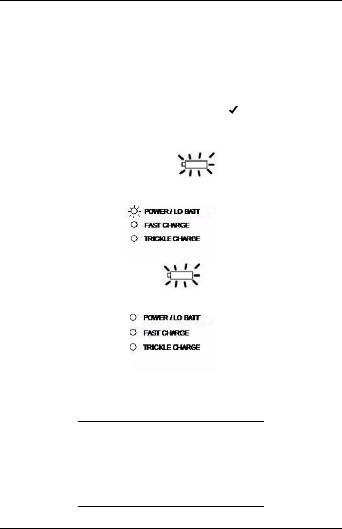
Low Battery Indication
Base station Low Battery - The battery icon on the handset flashes empty
and the ‘POWER/LO BATT’ LED on the base station flashes.
Handset Low Battery - The battery icon flashes empty and the ‘POWER/
LO BATT’ LED on the base station is not affected.
The low battery warning is five minutes, if the analyzer is not either placed on charge
or switched OFF within that time, the base station will power down automatically, in
this event the handset will display the following screen.
LANG, IDIOMA
US English
Français
Español
COMMS LOST
Test terminated.
S o m e d a t a l o s t .
Low Battery
-OK

Getting Started
44
Press to proceed and the handset will prompt you to save the results and to
remove the probe from the exhaust.
Note: Any saved data will state ‘Some Data Lost’ due to loss in Communications when
the base station is powered down. Likewise, if the data is analyzed on the PC
software, any data lost will be clearly indicated and all the gas readings for that part
of the test will be recorded as zero. After data has been either saved or discarded, the
handset will automatically shut down.
Out of Range
The OmiScan Gas should function normally with the handset up to at least 10 metres
(30 feet) away from the base station. However, if the handset is taken out of range
the display communication icon will disappear and the following text will be displayed:
If the handset is taken back within range within a few seconds, the handset will revert
to the previous screen shown before it was taken out of range.
At the end of the test the handset will give a warning ‘Some Data Lost’ giving the
option to save the test.
Note: Any saved data will state ‘Some Data Lost’ due to loss in communications when
the base station is powered down. Likewise, if the data is analyzed on the PC
software, any data lost will be clearly indicated and all the gas readings for that part
of the test will be recorded as zero.
WARNING
Base station out of
range
X-Abort
X
LIVE READINGS
Some data was lost
during the test
due to signal loss.
-OK

Getting Started
45
If, when out of range, the handset stays out of range the message above will be
displayed.
You will be given the option of saving the data that was captured up to the point of lost
communications.
TEST RESULT 3
Live Readings
Time: 14:07
Date: Feb 21 08
-Save X-Erase
LIVE READINGS
Test terminated
due to signal loss
-OK

PC Gas Analyzer Software
46
PC Gas Analyzer Software
System requirements
The minimum PC system requirements to load the OmiScan Gas Analysis Utility
software are:
•Windows Server 2003, Windows Vista Business, Windows Vista Business 64-bit
edition, Windows Vista Enterprise, Windows Vista Enterprise 64-bit edition,
Windows Vista Home basic, Windows Vista Home Basic 64-bit edition, Windows
Vista Home Premium, Windows Vista Home Premium 64-bit edition, Windows
Vista Starter, Windows Vista Ultimate, Windows Vista Ultimate 64-bit edition,
Windows XP Service pack 2 or later.
Required software: Windows Installer 3.1 or later is recommended.
IE 6 or later (required for loading .NET Framework).
•Intel or AMD 1200MHz processor or higher
•512 MB RAM (This is the recommended requirement by MS for the above
operating systems)
•330 MB (x86), 660 (x64) of free disk space
1024 X 768 minimum screen resolution
CD ROM or DVD Combo drive
USB 2.0
The requirements above are the minimum, the higher the PC specification the better
the operation of the analysis software.
Installation
The PC software, including the necessary drivers for the handset USB connection,
are on the CD that is supplied as part of the OmiScan Gas PC kit.
Insert the CD into the CD drive of the PC and the installation program should
AutoStart, if there is no response, start Windows Explorer, click on the CD drive and
identify the setup.exe file. Double click on this file and the installation should now
proceed.
Using the Software
Double click on the OmiScan Gas icon on the desktop. The OmiScan Gas application
will start to load. You can also use the ‘All Programs’ menu to access the application;
press the start button at the bottom left hand side of the screen, press ‘All Programs’.
From the displayed list select Omitec\OmiScan Gas\OmiScan Gas Analysis Utility.
PC Gas Analyzer Software
47
Analyzer Software Functions
The OmiScan Gas Analyzer provides the facility to view the data collected by the
OmiScan Gas handset, which is transferred to the PC. The data is analyzed in bar or
line graph format.
The title bar displays ‘OmiScan Gas Analysis Utility’ and five ‘buttons’:
•CSV File - Export the current test as a Comma Separated Values (CSV) file
•Bitmap file - Export the currently visible graph section as a bitmap
•Save - Saves the test currently being quick viewed
•Search - Searches the tests saved to PC using the selected search criteria
•Print - Prints the test details and the visible graph section
The buttons will be ‘disabled’ if they are not applicable to the function currently on
screen.
There are six tabs to select screens and the default screen is ‘Search’, which is the
second of the tabs:
•Handset Results
•Search
•Results Details
•Graph
•Setup
•Help
PC Gas Analyzer Software
48
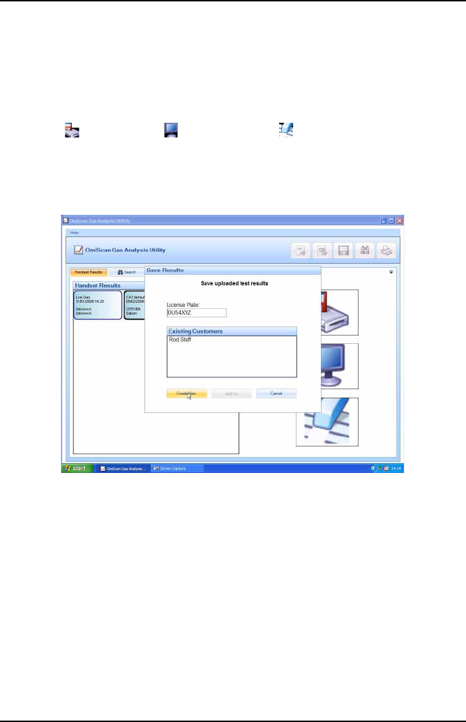
Handset Results
When the handset is connected to the PC with the USB cable, communication with
the handset is established; the left hand pane displays all of the stored vehicle test
results in the handset identified by test type, date, license plate details and
manufacturer. The right hand side displays three icons representing the functions of
‘Save data’ , ‘Display data’ and ‘Delete data’ . To activate any of these
functions, click and hold the left mouse button over the data item, drag the item over
the desired function, release the left mouse button.
Note: Handset Results tab will be disabled if the handset is not connected.
‘Save Data’ will display a dialog box prompting you to select either ‘Create New’ or
‘Add To’ one of the list of existing customers. When the data is saved the screen will
automatically change to ‘Results Detail’. To use the ‘Add To’ save option the license
number, or part of it, must be entered.
PC Gas Analyzer Software
49
‘Display Data’ will automatically load the data into the ‘Graph’ screen. The ‘Save’
button in the title bar is now activated and when pressed displays the same dialog box
as in ‘Save Data’ above.
‘Delete Data’ displays a dialog box asking you to confirm deletion.
PC Gas Analyzer Software
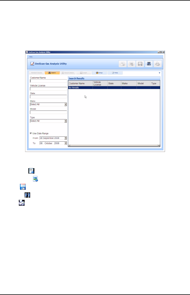
50
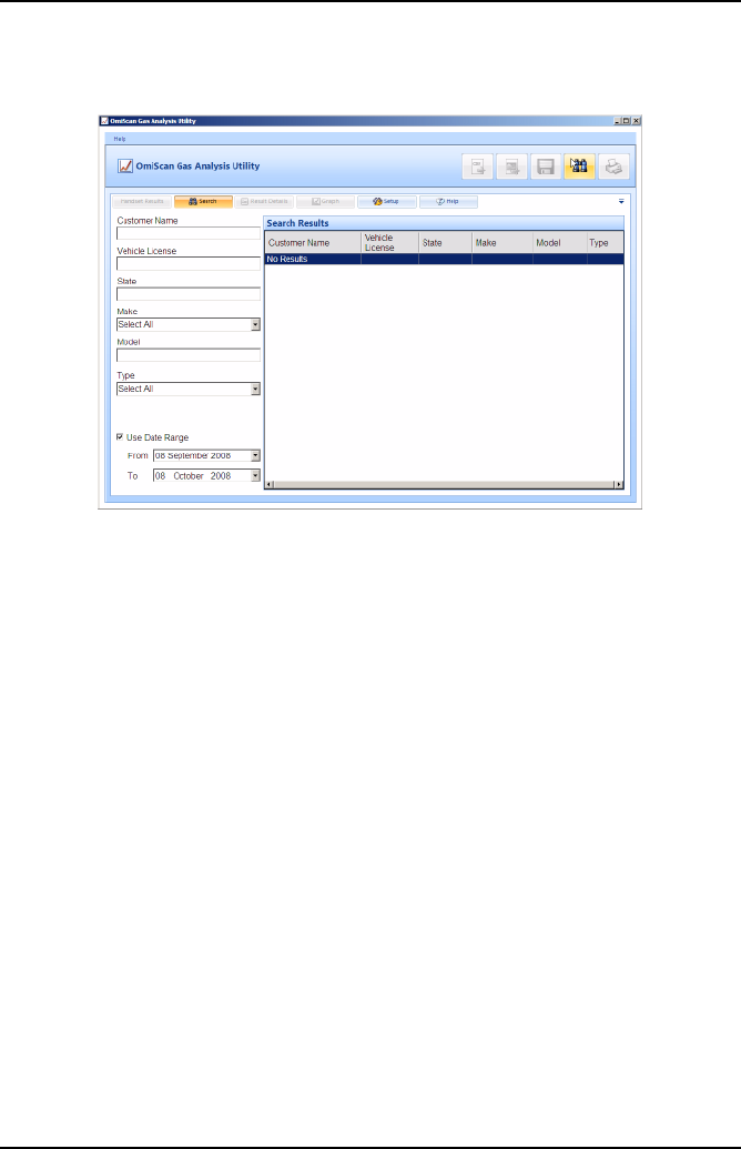
Search
‘Search’ allows stored data to be retrieved for later analysis, reference, historical
recall etc. A general search for all stored data files can be started by pressing the
‘Search’ button (binoculars).
PC Gas Analyzer Software
51
A specific search can be initiated from one or all of the following input cells:
•Customer Name
•Vehicle License
•State
•Make
•Model
•Type
•Use Date Range with ‘From’ and ‘To’ date selection
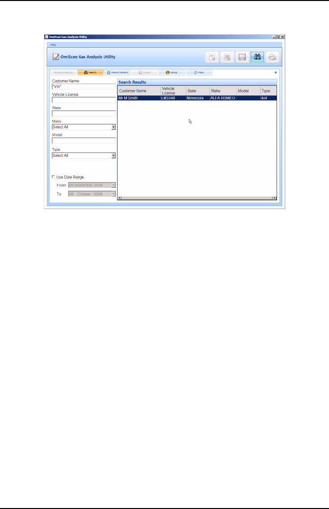
Any text item used as a search parameter can have a ‘wildcard’ character ‘*’ within it
if the whole text is not known. For example, if searching for a vehicle but the whole
registration is not known, entering ‘OU5*’ will match with any registration staring with
those characters.
With data input, pressing either ‘Enter’ on the keyboard or the ‘Binocular’ button in the
title bar will invoke a search with the result/s displayed on the right hand side of the
screen.
Select and double click on a file and the screen will change to ‘Result Detail’. The left
pane will list all of the tests completed on the vehicle; the test list is expanded by
double clicking on the ‘+’ sign. Double clicking on a specific test will change the
screen to ‘Graph’ displaying the data from that test. Selecting a test and then clicking
on the ‘Graph’ tab will also display that data in graphical detail.
PC Gas Analyzer Software
52
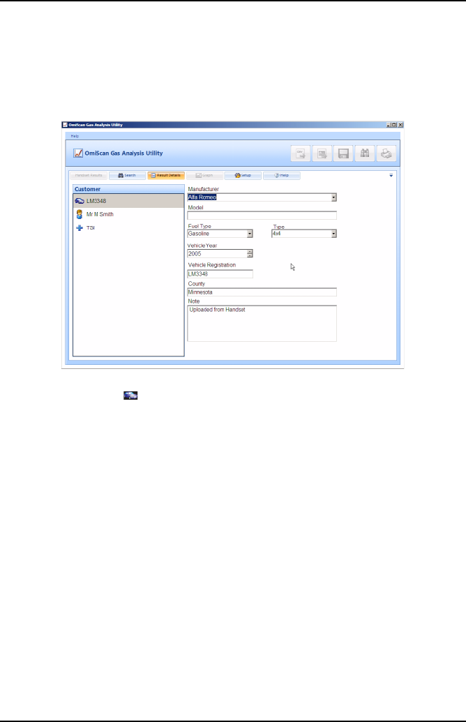
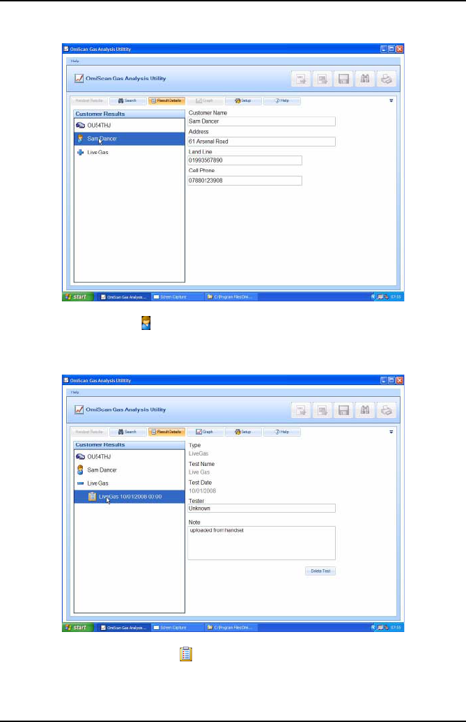
Results Detail
The ‘Results Detail’ saves the test data under the vehicle rather than customer,
therefore any new data from an already saved vehicle will be added to the vehicle
records. The vehicle records are listed in the left pane in three areas.
Car Symbol (License)
•This lists details of make, type, year, fuel type, State and an area for you to add
notes. (The data is down loaded from the handset but can be edited.)
PC Gas Analyzer Software
53
Man Symbol (Customer)
•Cells are available to enter customer’s details.
Clipboard Symbol (Test results)
•Each test is identified by type, test name, date, tester’s name and notes area.
Note: Selecting any test will enable the ‘Graph’ tab.
PC Gas Analyzer Software
54
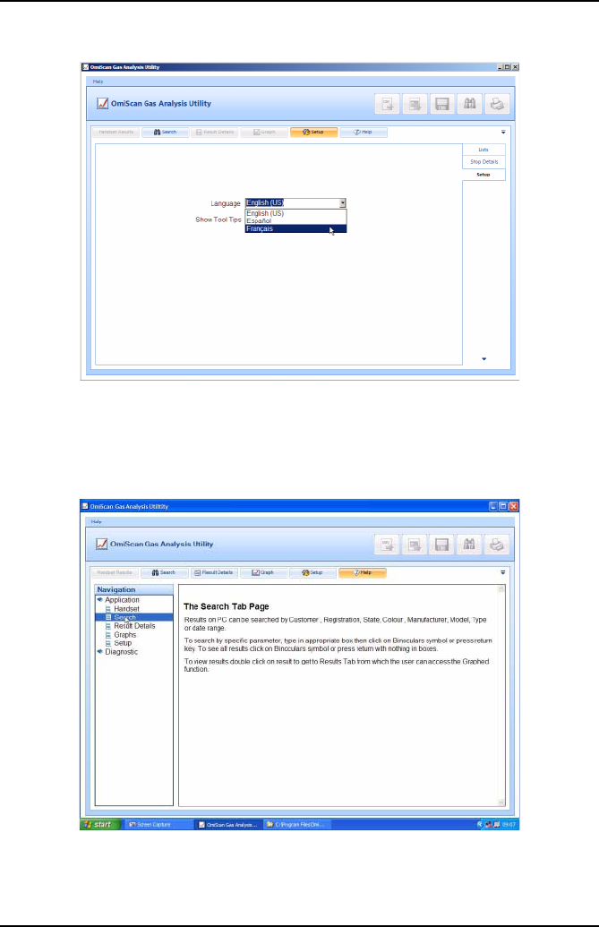
Graph
Test Result can be presented in raw data line graph format or by test specific bar and
line graphs. The available graph views depend upon the type of test carried out but
the raw data line graph is always available.
The test specific graphs (identified by ‘R’ on the graph icons) present a view of the
data, but not the raw data, from only a portion of the entire gas recording. This may
be, for example, the last 10 seconds of readings as an average. The bar graph option
displays the highest levels within this data portion whilst the line graph will plot this
data portion against time.

PC Gas Analyzer Software
55
The raw data line graph is available for all tests and is a plot of non-adjusted values
against time.
On the graph tab you can export the test results into a CSV file by pressing the file
button on the top tool bar. You can also export the graph image as a bitmap by
pressing the picture button on the top tool bar.
PC Gas Analyzer Software
56
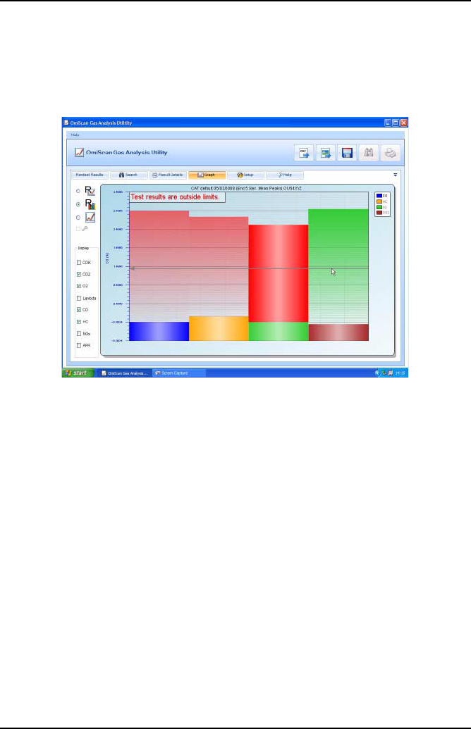
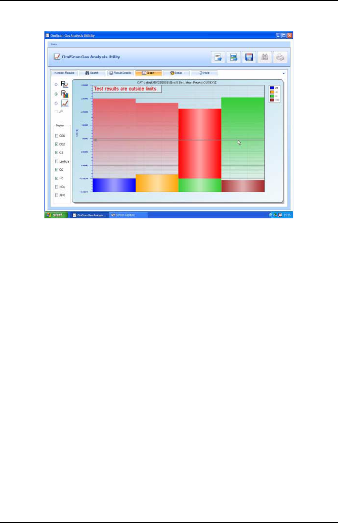
Bar graph: Readings that can be selected are: CO, CO2, O2, HC, NOx, MPH, AFR,
and LAMBDA. On opening results the displayed readings will default to relevant
gases. For example, if the test was a CAT then CO, CO2, HC, NOx and O2 will be
displayed. Because all gases are recorded during a test they can be added to the
graph by clicking on the gases in the DISPLAY bar down the left hand side of the
screen.
The scale of the Y axis can be changed to read any gas by selecting from the key
down the right hand side of the screen, double click on the gas required.
If preset cut off points are set in test then the gas colour will change to red over the
cut off point, therefore any area in red is in excess of the predefined acceptance level.
A horizontal guide line, moveable with the mouse, helps the user to read gas values.
For a print out of result, click on ‘Printer’ symbol in the top right hand corner of the
screen, when pressed you are prompted for language of print out – English, Spanish
or French. A prompt will be displayed for which graph is to be printed. The Garage
Details, vehicle details and time and date stamp will be added to the print out.
PC Gas Analyzer Software
57
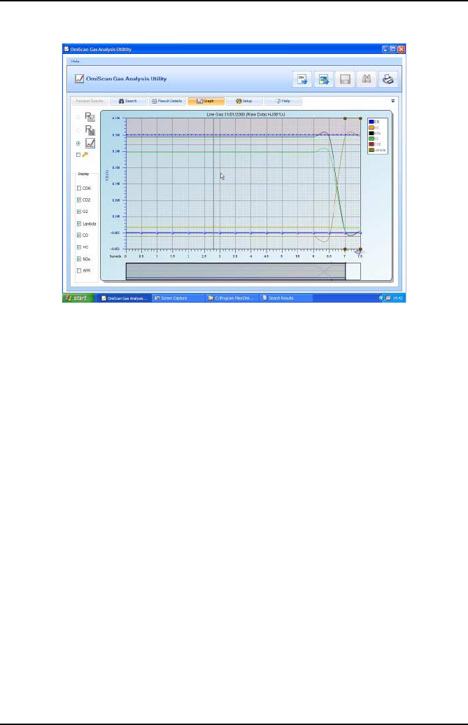
Line graph: CO, CO2, O2, HC, NOx, MPH, RPM, AFR and LAMBDA are plotted
against time.
•Gases displayed depend on type of test, but like bar graph mode other gases can
be added to plot.
•Y axis scale can be selected to a chosen gas and its graph will become bolder.
•Cut off limits will be shown on plot for the active series.
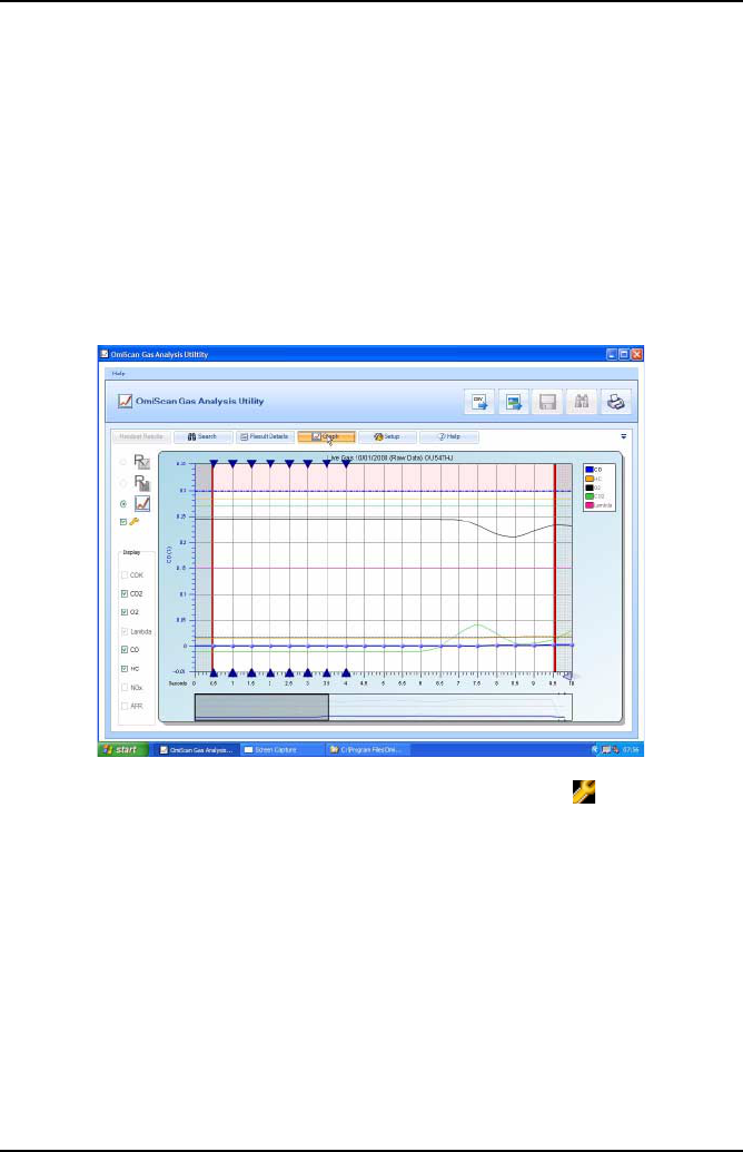
•A Landscape graph (only available on the raw data graph view), showing a
complete record of the gas readings, is under the main display. The Main display
seen on the screen will be presented as a window on the landscape graph. To view
readings anywhere through out the test sequence simply click and drag landscape
window. To zoom in or out further on a reading click on arrows in the bottom right
hand corner of the main graph.
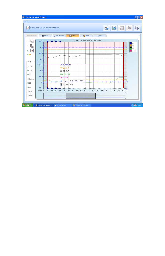
•To interrogate gas readings further, hold mouse anywhere in the main graph. A
vertical ‘Wand’ will appear and when held over a reading a ‘INFO’ box (only
available in raw data graph view) will appear. This box will:
1. Display gas values on plot.
2. Give Cut off Status – A green tick indicates all gases are below cut off points, a
red exclamation mark will list all gases above limits whether they are on the plot
or not.
3. Information speech bubble – based on combination of gas readings a suggested
diagnostic hint on what could be wrong with the vehicle will be displayed. Simply
click on bubble to revert to a diagnostic guide.
PC Gas Analyzer Software
58
4. Add ‘Snap Shot/View Snap Shot’ Camera symbol – Click on camera symbol to
add user comment and save. A green circle will be placed top and bottom of both
graph displays to tag Snap shot.
Note: Any Snap shot made during a test by pressing the Camera button on the
handset will be automatically tagged on graph. To view a Snapshot, click near
the diamond on the landscape graph to set the window over snapshot, place
mouse over reading on main graph to bring on the INFO box then simply click on
‘VIEW SNAP SHOT’. To delete Snapshot click Delete when viewing Snap shot
information.
5. Print out function is the same as Bar graph mode.
When the graph is in line view you can select the analyze button (below the line
graph button), left hand side of screen.
PC Gas Analyzer Software
59
This will activate diagnostics for the current visible frame of graph. Any possible
diagnosis made within this section will be displayed as a blue triangle as a prompt to
move the cursor to that graph point. Once the mouse is over that point, the ‘INFO’ box
will be displayed as normal. The purpose of this is to be able to quickly check a
section of graph for possible diagnosable problems.
PC Gas Analyzer Software
60
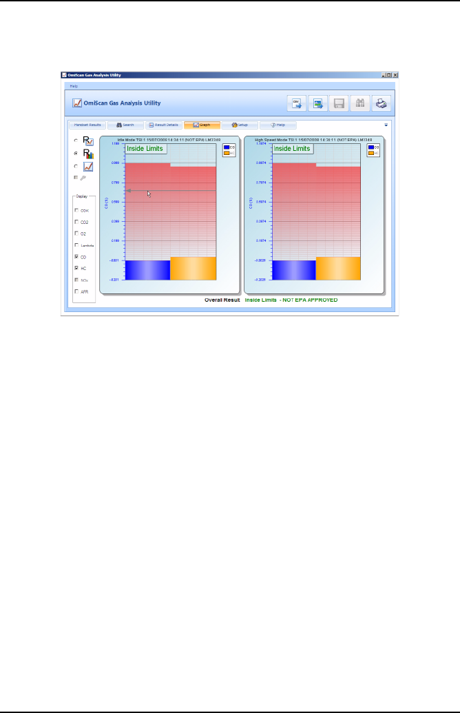
TSI Graph
The left hand bar graph indicates CO and HC values for the idle mode section of the
test. The right hand bar graph indicates the CO and HC values for the High Speed
Mode of the test. A window in the top left hand of each graph will state ‘Inside Limits’
or ‘Outside Limits’ as the case may be.
Note: ASM graph - Test result will be presented as a single bar graph indicating the
CO, HC and NOx values from the test. Again ‘Inside or Outside Limits’ will be shown
as appropriate.
Setup
The setup section has four sub-sections selected by tabs on the right of the screen:
1. Tests
2. Lists
3. Shop details
4. Setup
PC Gas Analyzer Software
61
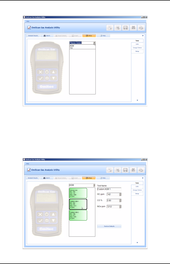
Tests
Both the ASM and TSI simulated tests offered by the OmiScan Gas can be carried
out using different limits (Cut points). Each Test offers two sets of Custom limits as
well as a set of default limits. The PC analyzer software allows the custom limits to be
changed on the handset. Click on Tests Tab then on the drop down menu arrow to
list tests.
Click on either ASM or TSI to list limits. If the limits on the handset match those on the
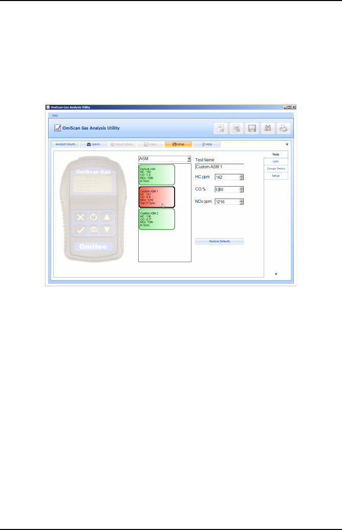
PC Gas Analyzer Software
62
PC Analyzer software the limits will be displayed in green (In Sync). Click on either of
the Custom limit boxes to display the individual gases and their limits. To change
limits click on up or down arrows for the relevant gas to set the desired value. Click
on limit box or press return on the PC keyboard to enter value. The test limit box will
change to Red to show the test limits on the handset no longer match those set on
the PC Analyzer software (Out of Sync).
To update the handset with the new edited test held in the PC, click and hold over the
specific test to transfer, and drag the test over the handset image and release the
mouse button.
On completion of downloading, the list box will change from red to green.
Note: Drag and drop facility will be disabled whilst the handset is disconnected from
the PC.
PC Gas Analyzer Software
63
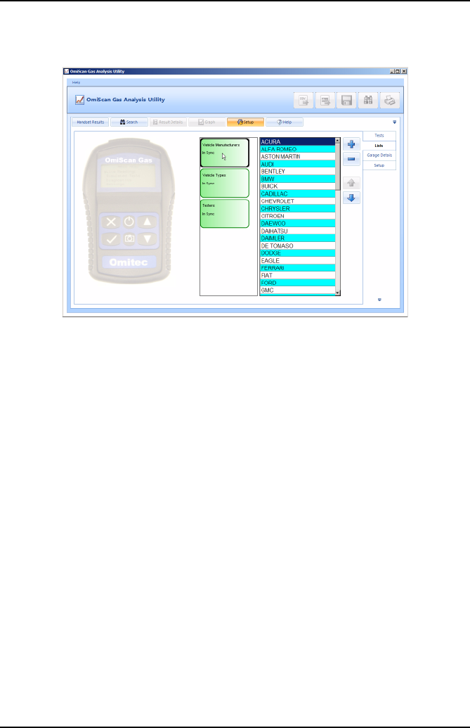
Lists
Vehicle make, vehicle types and testers can be edited and saved to the handset by
using the drag and drop facility. Double click on any of the lists, ‘Vehicle Makes’,
‘Vehicle Types’ or ‘Testers’ and the current data stored on the handset is shown in
the right pane.
The + button can be used to add to a list, likewise, the - button can be used to delete
from a list. Any list will be in alphabetical order. To position an item, for instance, a
vehicle make towards the top of the list, click on the appropriate make then click on
the Up button to move it up the list. This useful feature allows the list to customized
to individual requirements.
Like Tests a list will be either green if the list is In Sync with the handset and Red if
list is Out of Sync with the handset.
PC Gas Analyzer Software
64
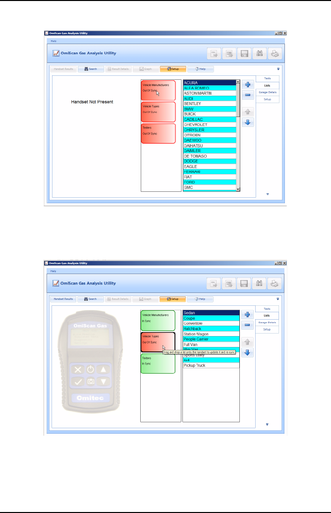
If the Handset is not connected to the PC there will be no picture of the Handset and
a warning ‘Handset Not Present’ will appear in the left pane and the status of any lists
or tests will be red.
PC Gas Analyzer Software
65
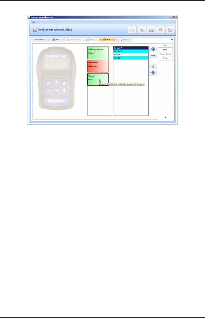
The lists for Vehicle type and Tester can be edited in the same way as Vehicle Make.
Again like Tests to update the handset to the list held in the PC, click and hold over
the specific list to transfer, and drag the list over the handset image and release the
mouse button.
On completion of downloading, the list box will change from red to green.
Note: Drag and drop facility will be disabled whilst the handset is disconnected from
the PC.
PC Gas Analyzer Software
66
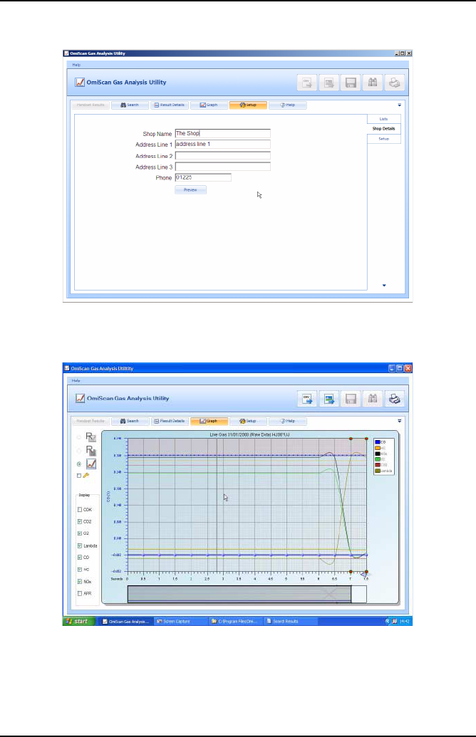
Shop: Contained in the PC and is added to the print out.
If no printer is installed on the PC a print preview is not available and warning will be
shown if the ‘Preview’ button is pressed.
PC Gas Analyzer Software
67
Setup: Sets language and enables/disables tool tips.
Help
The help tab will link to a document providing a guide to the functionality tabs. The
Navigation pane on the left also allows access to the diagnostic documents that are
linked from the dialog box in the ‘Graph’ section if any of the gases are out of limits.

PC Gas Analyzer Software
68
Communications
The Bluetooth® Wireless Technology communications provides connection between
the base station and the handset. The base station has a unique addresses and it is
advisable to note this address in the data section of this manual, especially if either
unit is replaced.
Software Build
Details of the software version and build can be accessed from the ‘Help’ function in
the top bar left hand side. Click on this function and then on ‘About’ will display a
dialog box containing version and build details of the OmiScan Gas PC Analyzer
Utility program.
Gas Analysis
69
Gas Analysis
OmiScan Gas Analysis of Results
CO -Carbon Monoxide - Carbon Monoxide is the product of incorrectly burned fuel,
so the obvious aim is to ensure that the CO level is as low as possible, the better the
combustion the lower the CO. However, due to unavoidable inefficiencies with
Internal Combustion Engine (ICE) there will always be an output of CO.
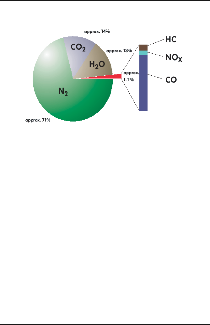
CO2 - Carbon Dioxide - Carbon Dioxide is the result of correctly burned fuel so the
obvious aim is to ensure that the CO2 level is as high as possible, typically 13% - 15%
for a catalytic converter vehicle. Non-cat would be typically 11% - 12.5%.
HC - Hydrocarbons - Hydrocarbons are basically unburnt fuel and so the obvious aim
is to have HC as low as possible but inefficiencies mean there is always an output of
HC.
O2 Oxygen - Oxygen has to be present for combustion to take place so obviously the
aim is to have as little surplus oxygen as possible, typically up to 2%.
NOx - Nitrous Oxide is a gas generated by high combustion temperature and
pressure and this can be reduced by design of the exhaust and inlet valve overlap and
exhaust gas recirculation where the inert exhaust gas introduced into the inlet will
reduce the combustion temperature. NOx can only be measured when the engine is
under load.
AFR/Lambda - Air Fuel Ratio (AFR) or Lambda is the ratio of air to fuel and is
calculated from the amount of oxygen sensed in the exhaust gases.
From the exhaust gases the following relationships are formed:
•O2 combines with CO to form CO2
•CO is an indicator of air fuel mixture richness
•HC is an indicator of fuel mixture leanness or richness and misfires
•CO and O2 are equal at the stoichiometric air/fuel ratio

Gas Analysis
70
•CO2 and O2 are indicators of the integrity of the exhaust system and/or the sample
hose and probe
•CO2is an indicator of combustion efficiency that peaks at or near the stoichiometric
air/fuel ratio and decreases with rich or lean air/fuel ratios
•If CO2 increases, O2 decreases (inversely related)
If O2 increase, CO2 decreases (inversely related)
During a cold start, and no secondary air injection, CO will be above 1% and the
catalytic converter will be O2 starved and will not ‘fire’ and the emissions will be the
same as pre-cat levels
Corrected CO
The Live Readings test offers the selection of Corrected CO (COK).
Corrected CO takes into account any dilution of the sampled gas, for example leaks
in the exhaust pipes and silencers. The formula to calculate COK is:
COK = CO x 15/CO2
When stoichiometric combustion is achieved and there is no dilution, the CO2 value
drops to approximately 15%, therefore, the correction factor is unity. If the sample is
diluted with air, the CO2 value falls below 15% and the correction factor is <1.
Non-Catalyst Systems
Perfect combustion in an ICE has an AFR of 14.7:1. This is measured by weight, any
reading higher than 14.7 indicates a lean mixture and likewise any reading lower than
14.7 indicates a rich mixture. For diagnostics purposes the AFR must be settled at
14.7:1 before analysing any other gas reading. With AFR correct the following table
shows how the levels of other gases can indicate a problem with the engine with
relation to the time of combustion.
Non-Catalyst System Gases with AFR
These readings are typical and reference should be made to the manufacturers’
specifications, which usually only refer to CO and HC. Setting the CO level correctly
should bring the other gases to high CO2, low HC and low O2.
AFR 14.7
Gas Perfect Minimum Maximum Problem
CO In Specification
CO2Highest possible 11% Before combustion
HC Lowest possible 400ppm During combustion
O2Lowest possible 2% After combustion

Gas Analysis
71
Catalyst Systems
Where AFR is used for Non-Cat systems, Lambda is used for Cat systems and the
engine management systems control Lambda to 1. Any value >1 is a lean mixture and
anything <1 is a rich mixture.
Catalyst System Gases with Lambda
The catalytic converter converts CO and HC into water (H2O) and extra CO2. Cats
increase the CO2 level, therefore they are useful for reducing acid rain rather than the
ozone layer. With a good operating system it should be possible to achieve 0 for both
CO and HC under normal operating conditions.
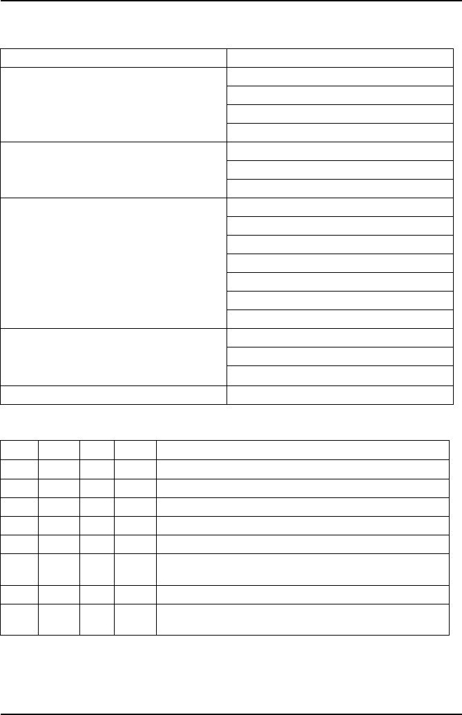
Fault Diagnosis
The following tables show various relationships between gases and suggest a
possible cause for these gas levels. H = High, VH = Very High, L = Low, VL = Very
Low, N = Normal.
5 Gas Relationship
Lambda 1
Gas Perfect Minimum Maximum Problem
CO In Specification 0.5
CO2Highest possible 12.5% 15 Before combustion
HC Lowest possible 50ppm During combustion
O2Lowest possible 2% After combustion
HC O2CO CO2NOx Possible cause
H VH Vacuum leak
H H VL Overactive EGR valve
H L H L L Running rich
H H H L H Running lean
H Increased combustion pressure or VH O2 after
combustion
VH N VL VL Zero Blown head gasket
HHHL H Faulty CAT
Gas Analysis
72
High Gas Levels
4 Gas Relationship
Gas Possible cause
High CO EVAP system problem
PCV system problem
Fuel system problem
Control system problem
High HC/CO Fuel system problem
Running rich
Blown head gasket
High HC Mechanical system problem
Electrical system problem
Fuel system problem
Running lean
Warm air intake problem
Cat problem
EVAP system leak
High NOx High combustion pressure
High combustion temperature
High O2 content
High HC/NOx Cat problem
CO CO2HC O2Problem
H L H H Rich mixture with ignition misfire
H L H L Faulty thermostat or ECT sensor - rich mixture fault
L L L H Exhaust leak after Cat
L H L H Injector misfire with Cat at operating temperature
H L N H Rich mixture
H H H H Injector misfire, Cat not working - Rich mixture &
vacuum leak
L L H H Ignition misfire; lean mixture; unmetered air leak
L H L L Good combustion efficiency with Cat at operating
temperature

Gas Analysis
73
Lambda status
5 Gas - Catalytic Vehicle Typical Readings
These are typical limit values of the 5 gasses for fuel injected vehicles and are not
specific to any vehicle:
•CO < 0.3%
CO2 > 14%
HC < 200 ppm
O2 <1%
NOx < 100 ppm
Condition Result
Too lean Poor engine power
Misfiring at cruise speed
Burnt valves
Burnt pistons
Scored cylinders
Spark knock
Slightly lean High gas mileage
Low exhaust emissions
Reduced engine power
Slight tendency to knock
Stoichiometric Best all round performance
Slightly rich
Maximum engine power
Higher emissions
Higher fuel consumption
Lower tendency to knock
Too rich Poor gas mileage
Misfiring
Increased air pollution
Oil contamination
Black exhaust
Routine Maintenance & Cleaning
74
Routine M aintenance & Cleaning
Routine Maintenance
To ensure that the analyzer gives long and reliable service, regular cleaning and
changing of the filters is necessary. Failure to change the disposable coalescing filter
elements regularly may void warranty and service agreements.
Check the cleanliness of the disposable coalescing filter (Part No. FL5720A or OM
4700/11/10 (Pack of 10)) at the start of each day. If the filter shows signs of severe
contamination or a build up of deposits has occurred, remove and clean out the
housing using a lint-free cloth. Ensure that no deposits are pushed into the exit pipes
of the filter housing. Renew the disposable filter if heavily contaminated.
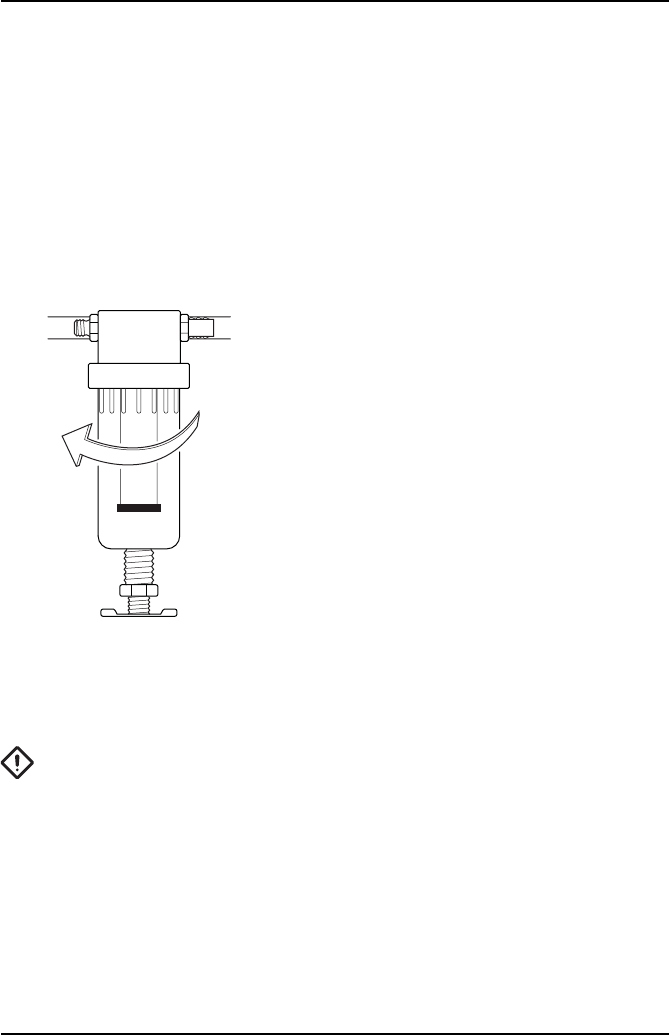
REPLACING COALESCING FILTER
To access Coalescing filter (FL5720A), firstly remove
clear catch pot from the water trap by unscrewing it
clockwise. Then unscrew black retaining column,
again clockwise to release filter.
Once replaced, screw filter back in and refit catch pot.
NOTE: Both filter and catch pot only need to be finger
tight. This will ease future filter replacement.
NOTE: Any dismantling of probe tip, sample hose or filters MUST be followed by a
manual leak test.
CAUTION: DO NOT run the analyzer without the filters in place!
At the beginning of each day, drain any water collected in the sample pipe and the
water trap.
OM1398

Routine Maintenance & Cleaning
75
DRAINING WATER FROM WATER TRAP
To drain water from the water trap simply screw the brass
drain fully clockwise.
When the water has drained, screw the brass drain fully
counter clockwise to seal water trap.
NOTE: The drain only needs to be finger tight. Do not
over tighten as this may deform the rubber seal. Always
conduct a Leak Test after draining the water trap to
ensure an air leak has not been introduced into the gas
sampling chain which will cause false readings. See
‘System Checks’ in ‘Gas Analyzer’ Menu.
The sample probe tip can be replaced as a separate item, or may be removed for
cleaning. Assembly will require a small quantity of “Loctite 222”, or similar thread
sealant, to be used on the threads to ensure a good gas seal.
At the start of each day, clean any accumulated deposits from the Sample Probe tip,
making sure that the two cross-drillings in the tip are clear and check that the analyzer
outlet pipes are not kinked or blocked in any manner.
Ensure that the analyzer is not operated in a dusty environment, especially areas
where paint spray and dust spray are present.
CAUTION: Contamination of the analyzer by paint spray or excessive dust may
void the warranty and/or service agreements!
Oxygen cell replacement procedure
When an exhausted oxygen cell is identified during a zero calibration, the handset
automatically links to ‘System Checks/O2 Cell Functions’. Select ‘Oxygen Cell Value’
to ensure that the O2 cell output is outside of the expected level of between 9mV and
11mV. If the cell has failed, change the cell as detailed:
1. Firstly ensure there are no leaks or blockages in the gas handling system. If a
blockage is found, clear and retest ‘Zero Calibration’, else proceed to 2.
2. Ensure power to the unit is switched off, then go to the rear of the unit and locate
the O2/NOx cells cover (see ‘Assembling the OmiScan Gas Analyzer’, page 8).
3. Remove the two retaining screws and remove the cover.
OM1399

Routine Maintenance & Cleaning
76
4. Disconnect the cable from the red oxygen cell. It may be advantageous to gently
prize the locking tab of the connector away from the mating half, to facilitate
disconnection.
5. Unscrew the cell by hand (unscrew counter-clockwise). If discarding the cell,
place to one side for later safe disposal.
6. With the new cell, ensure the “O” ring is properly seated against the thread
abutment. Screw in the cell (clockwise) to hand-tightness but do not over-tighten.
Ensure a gas tight seal. Refit the connector and screw the ground lead to the
centre post, making sure the NOx cell ground lead is also secured.
7. Ensure the Oxygen Cell is properly seated in the housing and provides a gas tight
seal.
8. Refit the cover, make sure the gas tubing is not crushed or trapped and secure
cover to the back of the unit.
9. Turn on the power to the unit and allow it to warm up. Ensure that the analyzer
is fully warmed up (i.e. that it has had at least 5 minutes since power on).
10. Use handset to configure the OmiScan Gas with the new O2 cell:
•
Select ‘Renew O2 Cell’.
•
This will reset the error code and recalibrate the Analyzer with the new cell.
11. If the unit still fails, contact your service engineer.
The O2 cell can be monitored to see if it is approaching the end of its life. This can be
done by checking its cell voltage. This should be done with the probe in clean air and
accessing the following menu on the handset:
•
Select ‘Gas Analyzer’ – ‘System Checks’ – ‘O2 Cell functions’ – ‘Oxygen Cell
Value’
A good cell should read between 9mV and 11mV. The Analyzer will automatically flag
up an error if the cell voltage falls below 7mV. It is recommended that the cell is
changed if voltage is nearing the 7mV threshold.
NOx Cell Replacement
In theory the NOx cell should have a life expectancy of 2 years. Unlike the O2 cell, the
OmiScan Gas will not flag an error in the NOx cell.
It is recommended, therefore, that the NOx channel, like the rest of the OmiScan Gas,
is regularly tested with calibration gases of known concentration. This can be carried
out by an Omitec authorized Service agent.
NOTE: Due to the operating characteristics of the NOX sensor, any necessary
replacement will need to be calibrated by an authorized Omitec authorized Service
agent using a NOx calibration gas.

Routine Maintenance & Cleaning
77
Calibration and Accuracy Checks
It is recommended that periodic Calibration and Accuracy testing should be carried
out on the OmiScan Gas Analyzer to ensure reliable and accurate testing.
It is also recommended that this be done once every 12 months on average. This can
be carried out by an Omitec authorized Service agent
Cleaning
OmiScan Gas unit
The surfaces of the analyzer cabinet can be cleaned with a soft sponge, dampened
with a mild soap and water solution.
CAUTION: ENSURE that the unit is disconnected from the mains before
cleaning. Be careful not to wipe electrical connections or connectors while
cleaning.
CAUTION: On no account use solvents or strong detergents to clean the unit.
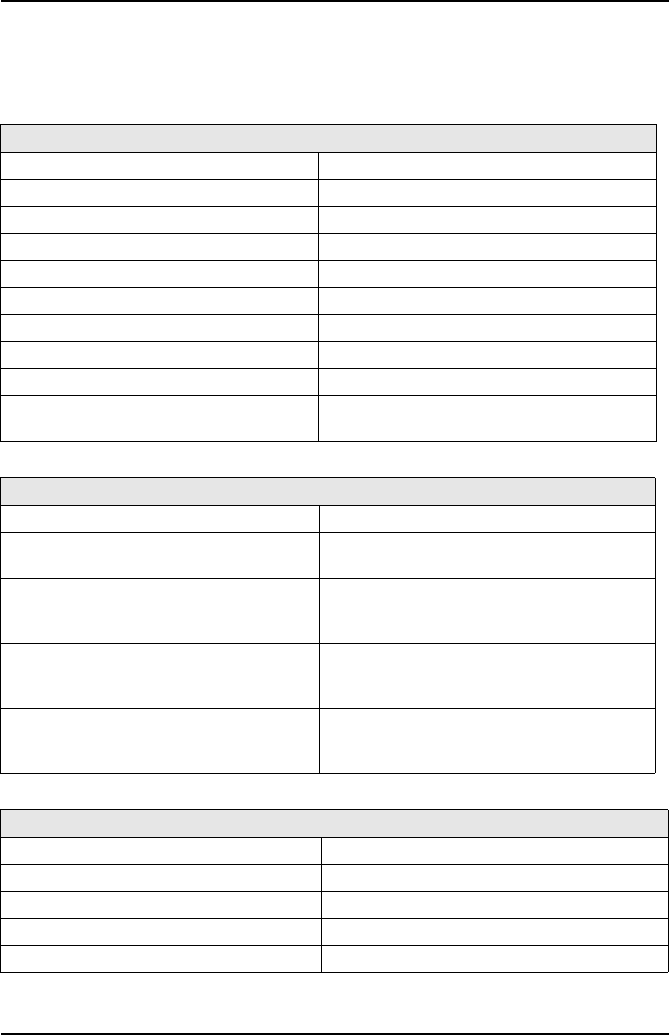
Technical Specification
78
Technical Spe cification
Technical Specification
The OmiScan Gas unit (Part No. OM 4720/1)
Environmental
Operational temperature range 0°C (32°F) to 45°C (113°F)
Operational temperature (nominal) 20°C (68°F)
Storage temperature range -4°C (24.8°F) to 70°C(158°F)
Relative Humidity (operational) 95% RH (non-condensing)
Relative Humidity (storage) 99% RH (non-condensing)
Atmospheric pressure range 813 to 1060 mBar
Atmospheric pressure (nominal) 1013 mBar
Altitude (operational) -300 m (-984 ft) to +3000 m (+9836 ft)
Sunlight No direct exposure to sunlight
Operating Constraints Designed for covered use only
Not for external use
Mechanical
Operating Position Horizontal
Ventilation Still Air
Free from strong drafts
Weight Total 2.21 kg (4.9 lbs)
Handset 400g (0.88 lbs)
Base 1.81 kg (3.97 lbs)
Dimensions of main unit 192 mm wide
283 mm deep
180 mm high (including 10mm feet)
Dimensions of handset 108 mm wide
160 mm deep
38 mm high
Charger Power Supply
Mains voltage range 100 – 240V AC
Mains frequency range 50-60 Hz
Power input 60 W
Base station battery pack 9.6V Nom. 8 cell rechargeable NiMH
Handset battery pack 2.4V Nom. 2 cell rechargeable NiMH
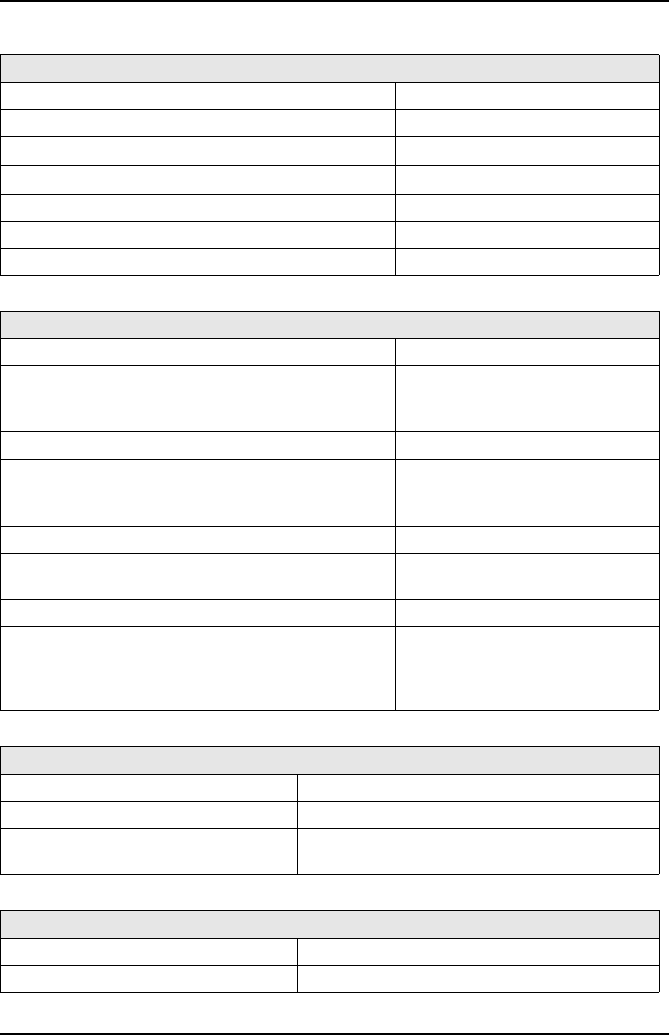
Technical Specification
79
Measurement range (OIML Class 0)
Carbon monoxide (CO) range 0 to 15% vol.
CO accuracy ±0.03% abs or ±5% rel.
Carbon dioxide (CO2) range 0 to 20% vol.
CO2 accuracy ±0.5% abs. or ±5% rel.
Hydrocarbons as n-hexane (HC) range 0 to 2000 ppm vol.
HC accuracy - 0 to 2000ppm ±10 ppm or ±5% rel.
PEF Factor 0.490 to 0.540
Transducer measurement range
Carbon monoxide (CO) range 0.00 – 15.00%
CO accuracy:
0.00% to 10.00%
10.01% to 15.00%
±0.02% abs. or ±3% rel.
±5% rel.
Carbon dioxide (CO2) range 0.00 to 20.00%
CO2 accuracy:
0.00% to 16.00%
16.01% to 20.00%
±0.3% abs. or ±3% rel.
±5% rel.
Hydrocarbons as n-hexane (HC) range 0 to 2000 ppm
HC accuracy:
0 to 2000ppm ±3% rel.
Hydrocarbons as propane (HC) range 0 to 30000 ppm
HC accuracy
0 to 4000 ppm
2001 to 15000 ppm
15001 to 3000 ppm
±3% rel.
±5% rel.
±8% rel.
Measurement of Oxygen
Oxygen range 0.00% to 25.00%
Accuracy ±0.01% abs.
Response time < 30s to 95% of final value
< 60s for change from 20.9% to < 0.10% vol.
Measurement of Nitric Oxide (NOx)
NOx range 0 to 5000 ppm
Accuracy ±3% rel.
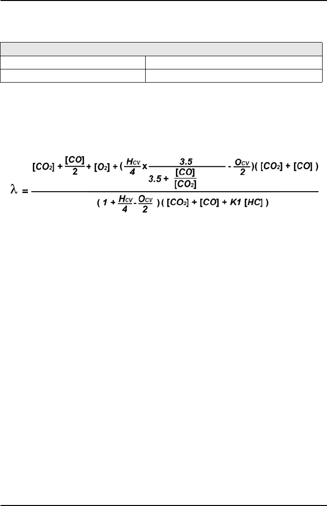
Technical Specification
80
Response time of analyzer: <15 secs to display 95% of final values (CO, CO2 & HC)
Calculation of Lambda value according to Brettschneider (Source: Bosch Technische
Berichte, VOL. 6 (1979) No. 4, p177-186) – As listed in OIMLR99 specification.
Simplified Lambda calculation:
General Data
Real time clock
The handset has:
•Day and Date, time in hours, minutes and seconds with automatic leap year
compensation.
•Time is user adjustable.
Handset
•Bluetooth® Wireless Technology Comms
Range typically 10m (30 feet)
PC Interface
•USB 1.1 or 2.0
Lambda Calculation (by Brettschneider formula)
Lambda range 0.0 to 2.0
Resolution 0.01
[ ] Concentration in % vol (ppm vol for HC)
K1 Conversion factor for HC if expressed in ppm vol n-hexane (C6H14) equivalent.
It’s value in this formula is 6x10⁻⁴
HCV Atomic ratio hydrogen to carbon (HCV = 1.7261)
OCV Atomic ratio oxygen to carbon (OCV = 0.0176)
Technical Specification
81
Ancillary Equipment
Pneumatic Specifications
Vehicle Supply Lead
Cable length 6 foot
For vehicles with auxiliary socket in the luggage compartment
Flow Rate
Analyzer Outlet (nominal) 1.0 l/min
Sample Inlet 1.0 l/min
Filtration
Coalescing element-PVDF Fluorocarbon 95%+
efficiency at particles > 0.1 microns
57 mm length
Oxygen Cell
City Technology CiTicel AO2
Calibration Gas
Minimum pressure 700 mBar above atmospheric
pressure
Flow rate 1.5 l/min
Composition (4 Gas):
Carbon dioxide 14% vol.
Carbon Monoxide 3.5% vol.
Propane 2000 ppm vol.
Nitrogen Balance
Composition NOx Calibration Gas:
NOx 1000 ppm
Nitrogen Balance
Technical Specification
82
Service and calibration frequency
Calibration - At 12 monthly intervals
Country Specific Approvals
FCC
OmiScan Gas Handset OM4720/2:
FCC CFR47, Part 15 Subpart B
This device complies with part 15 of the FCC Rules. Operation is subject to the
following 2 conditions: (1) This device may not cause harmful interference, and (2)
This device must accept any interference received, including interference that may
cause undesired operation.
Grantee and Equipment Product Code:
FCC ID: SV4-OM4720
‘We hereby declare that product OmiScan Gas Handset OM4720/2 is a class 2 BT
device (max 2.7 mW EIRP). Due to the low level of transmit output power the device
is not subject to the routine RF exposure valuation as per Section 2.1093 of the FCC
rules’.
OmiScan Gas Base Station OM4720/1:
FCC CFR47, Part 15 Subpart B
This device complies with part 15 of the FCC Rules. Operation is subject to the
following 2 conditions: (1) This device may not cause harmful interference, and (2)
This device must accept any interference received, including interference that may
cause undesired operation.
Note: This Product contains FCC ID: PI403B
Service
Replace disposable filter element (0.1 µm) –
Part No. OM 4700/11/10 (Pack of 10)
Weekly – if in continuous use,
else as necessary
Single disposable coalescing filter (0.1 µm) –
Part No. FL5720A
Weekly – if in continuous use,
else as necessary
In Line hydrophobic pancake filter –
Part No. FL5718A
As necessary
Cleaning of sample probe and hose Weekly – if in continuous use,
else as necessary
Replace oxygen cell - OM4000/12 Two years, or as needed
Replace NOx sensor - OM4700/12 Two years, or as needed

Technical Specification
83
INDUSTRY CANADA:
OmiScan Gas Handset OM4720/2:
RSS210, RSSGEN
Operation is subject to the following two conditions: (1) This device may not cause
harmful interference, and (2) This device must accept any interference received,
including interference that may cause undesired operation.
Company Number and UPN Number:
IC: 6220A-OM4720
‘We hereby declare that product OmiScan Gas Handset OM4720/2 is a class 2 BT
device (max 2.7 mW EIRP). Due to the low level of transmit output power the device
is not subject to the routine RF exposure valuation.’
OmiScan Gas Base Station OM4720/1:
RSS210, RSSGEN
Operation is subject to the following 2 conditions: (1) This device may not cause
harmful interference, and (2) This device must accept any interference received,
including interference that may cause undesired operation.
Note: This Product contains IC:1931B-EUSB.
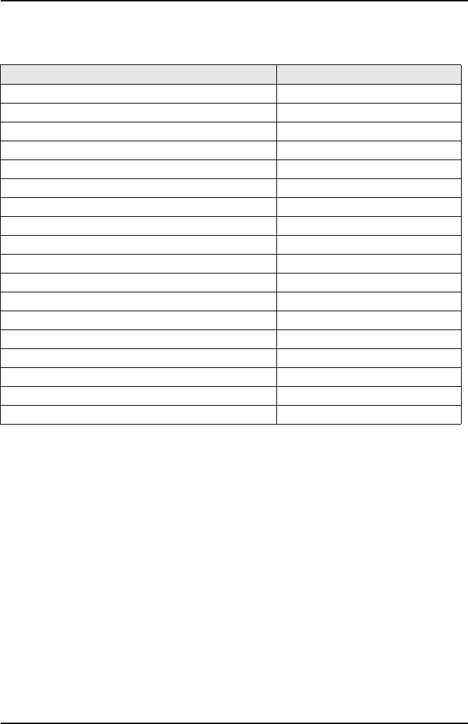
Technical Specification
84
Spare Parts List
Please quote the part number when ordering or enquiring about the availability or
price of spares for you OmiScan Gas analyzer.
Description Part number
Top level kit OM4720
Base station OM 4720/1
OmiScan Gas Handset OM 4720/2
PC Analyzer Application Software CD OM 4720/3
Instruction Manual OM 4720/4
Exhaust Sample Probe complete with hose OM 4700/5
Battery Charger PSU OM 4700/6
Handset 2 battery pack OM 4700/7
Base Station 4 battery pack OM 4700/8
Sample Probe Hose extension OM 4700/10
Coalescing Filter (box of 10) OM 4700/11/10
NOx sensor OM 4700/12
Vehicle power lead OM 4700/13
Oxygen Sensor Cell OM 4000/12
Sample Probe Cap RB4001A
OmiScan Gas USB Lead CB9166A
In line hydrophobic pancake filter FL5718A
Coalescing Filter FL5720A