Omron RFID Business Development Department V720SBC5D4A-US RF ID Reader User Manual
Omron Corporation, RFID Business Development Department RF ID Reader
UserManual.wiki
>
Omron RFID Business Development Department
>
V720SBC5D4A US User Manual
user manual
Navigation menu
Upload a User Manual
Namespaces
Wiki Guide
HTML
PDF
Info
Views
User Manual
Discussion / Help
Navigation

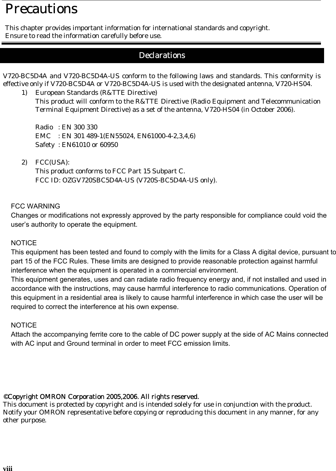
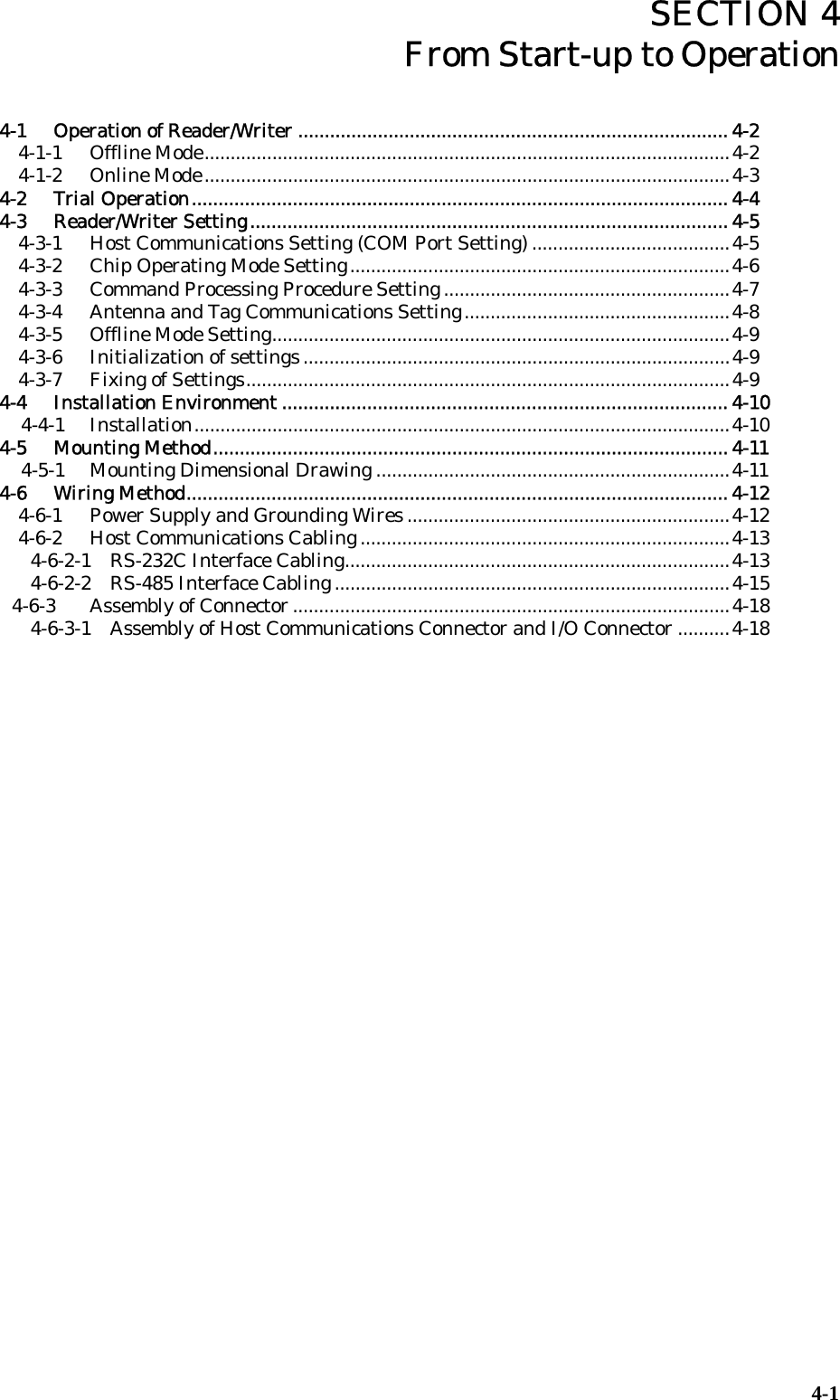
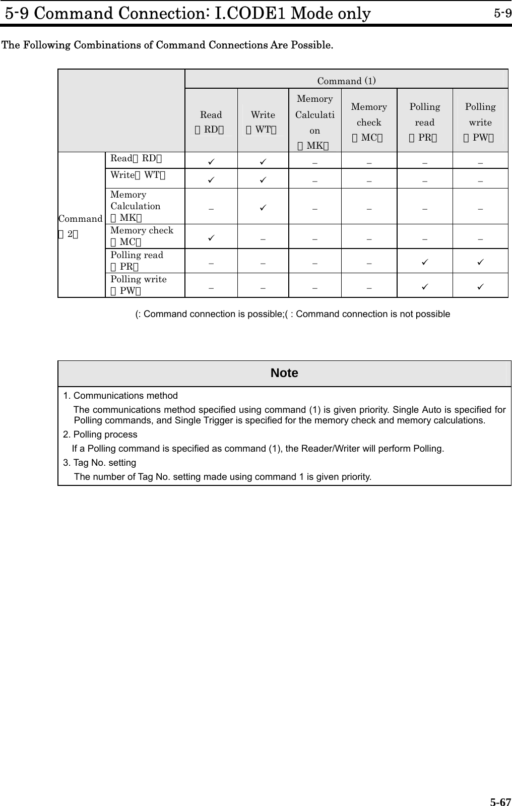
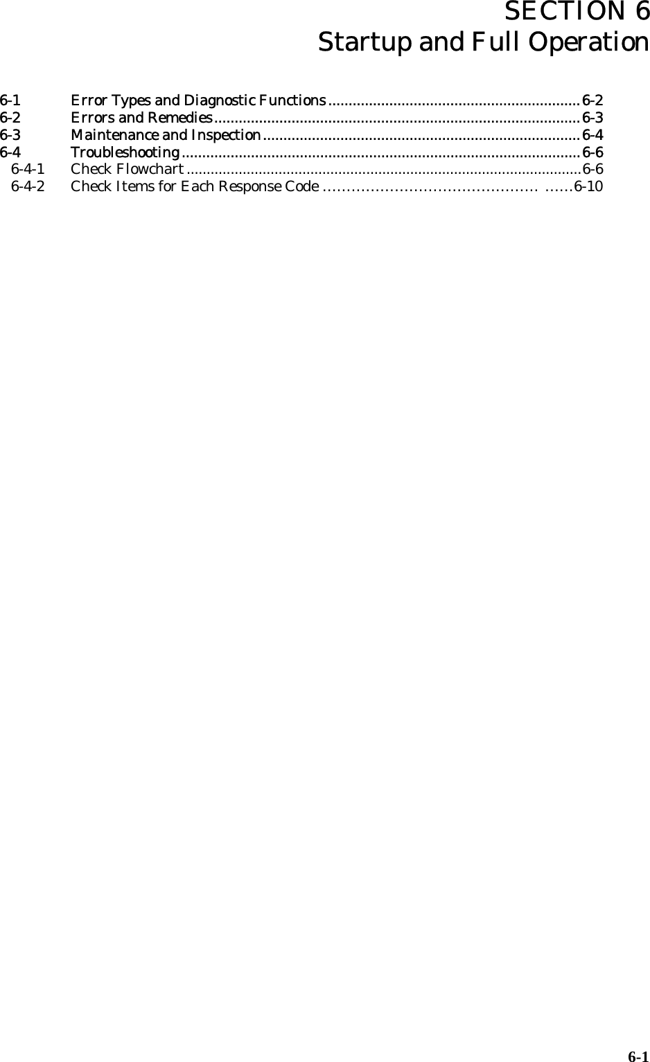
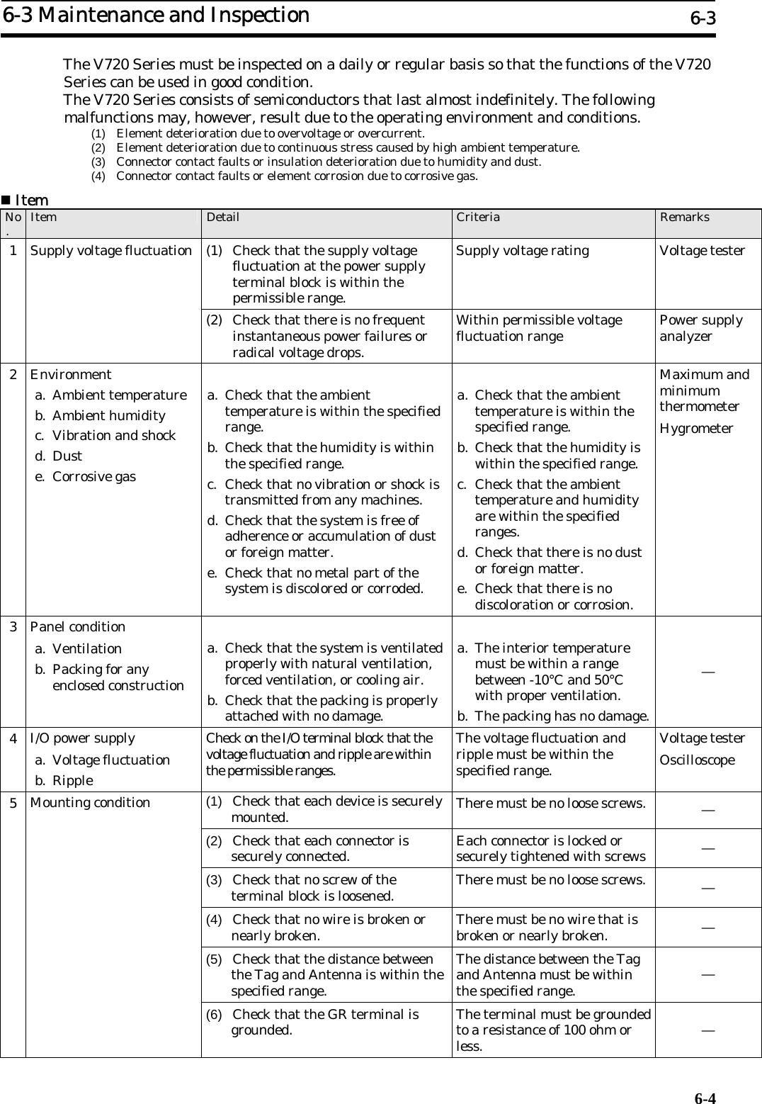
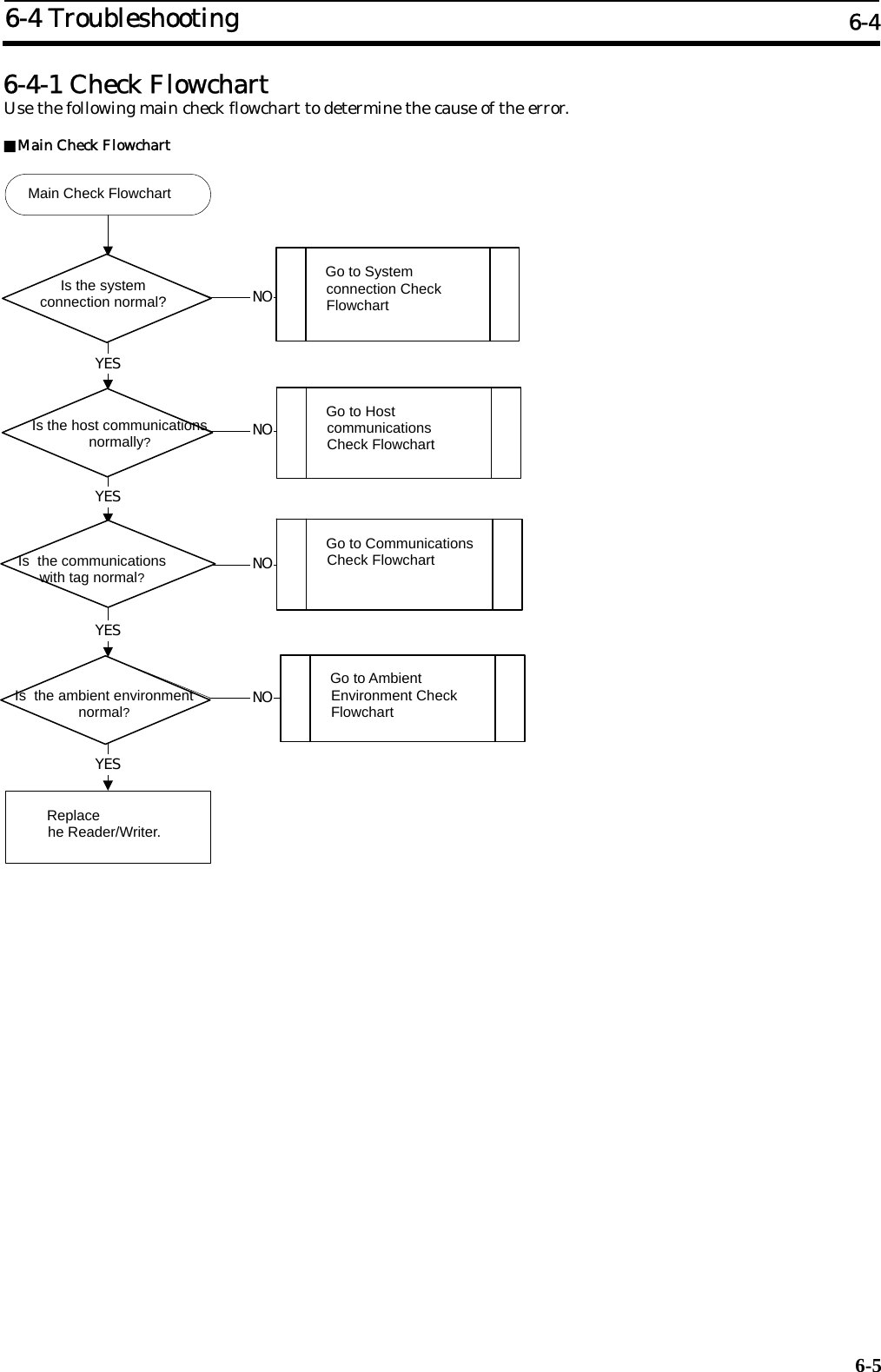
![TABLE OF CONTENS xi 5-4-2 Write (WT)...........................................................................................................29 5-4-3 Read (RD)-Tag Detection: I.CODE1 Mode only.................................................31 5-4-4 Read (RD)-UID Select/Specified Tag..................................................................32 5-4-5 Write (WT)-UID Select/Specified Tag ................................................................33 5-4-6 Read (RD)-Fast Read Access: I.CODE1 Mode only...........................................34 5-4-7 Polling Single Auto Read (PR)............................................................................35 5-4-8 Polling Single Auto Write (PW)..........................................................................36 5-4-9 Polling Check (PC)..............................................................................................37 5-4-10 Polling End (PE)..................................................................................................38 5-4-11 Memory Check (MC): I.CODE1 Mode only........................................................39 5-4-12 Memory Calculation (MK): I.CODE1 Mode only ..............................................39 5-5 System Command.................................................................................................... 40 5-5-1 System Read (SR): ISO Mode only.....................................................................40 5-5-2 System Write (SW): ISO Mode only...................................................................41 5-5-3 System Lock (SL): ISO Mode only......................................................................42 5-5-4 Read (RD)-SNR Read: I.CODE1 Mode only ......................................................43 5-5-5 EAS Setting (ES): I.CODE1 Mode only .............................................................44 5-5-6 QuietBit Setting (QB): I.CODE1 Mode only......................................................44 5-5-7 Lock Setting (LK): ISO Mode .............................................................................45 5-5-8 Lock Setting Read (LR): ISO Mode only............................................................46 5-5-9 Lock Setting (LK): I.CODE1 Mode.....................................................................47 5-5-10 EAS Check (EA) ..................................................................................................48 5-6 Reader/Writer Control Commands.......................................................................... 49 5-6-1 Stop (ST)..............................................................................................................49 5-6-2 Reset (XZ) ............................................................................................................49 5-6-3 ACK (AK).............................................................................................................49 5-6-4 NACK (NK)..........................................................................................................49 5-6-5 I/O Control Command (CC)................................................................................50 5-6-6 Test (TS)...............................................................................................................50 5-6-7 Version (VS).........................................................................................................51 5-7 Setting Command.................................................................................................... 52 5-7-1 Reader/Writer AFI Enable/Disable Changeover (AE): ISO Mode only............52 5-7-2 Reader/Writer AFI Value setting (AF): ISO Mode only ....................................52 5-7-3 Reader/Writer Family Code Setting (FC): I.CODE1 Mode...............................53 5-7-4 Reader/Writer Application ID Setting (AI): I.CODE1 Mode ............................53 5-7-5 UID/SNR Addition Setting (SN).........................................................................54 5-7-6 Node Number Setting (NN)................................................................................55 5-7-7 Communications Port Setting (CP)....................................................................56 5-7-8 Communications Type Setting (CT)...................................................................58 5-7-9 Tag Communications Mode Setting (CM)..........................................................58 5-7-10 Antenna Changeover (AC)..................................................................................59 5-7-11 Terminal Resistance Setting (TM).....................................................................59 5-7-12 Offline Mode Setting (FL)...................................................................................60 5-7-13 Set Value Initialization (IS)................................................................................61 5-7-14 Set Value Writing (EW).......................................................................................61 5-7-15 Chip Operating Mode Switch (TY).....................................................................62 5-7-16 Duplicate Communication Protecting Function Setting (MX) [Ver1.20 and higher] 63 5-7-17 I/O Automatic Changeover Setting (CA) [Ver1.20 and higher]........................64 5-8 Other Commands..................................................................................................... 65 5-8-1 Command Undefined Response..........................................................................65 5-9 Command Connection: I.CODE1 Mode only........................................................... 66 SECTION 6 Startup and Full Operation.............................................6-1 6-1 Error Types and Diagnostic Functions.....................................................................2 6-2 Errors and Remedies................................................................................................. 3 6-3 Maintenance and Inspection..................................................................................... 4 6-4 Troubleshooting ......................................................................................................... 5](https://usermanual.wiki/Omron-RFID-Business-Development-Department/V720SBC5D4A-US/User-Guide-710365-Page-11.png)

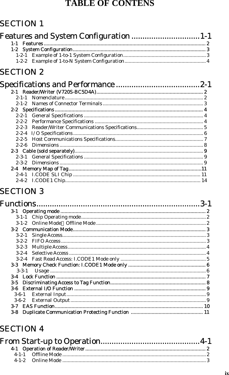
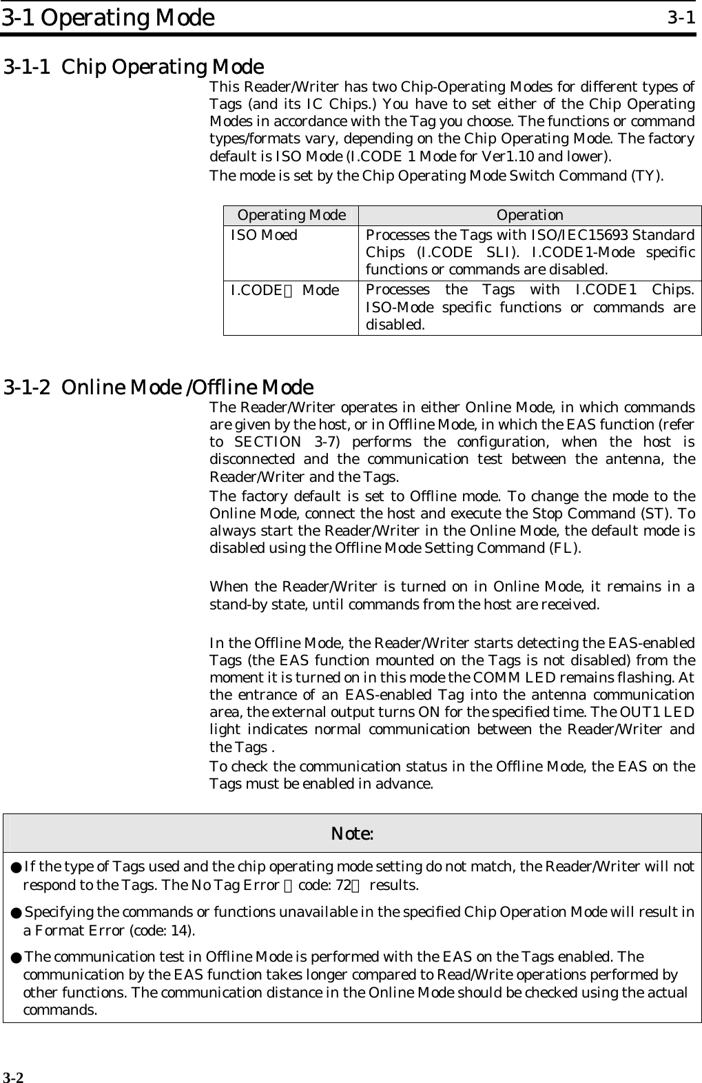
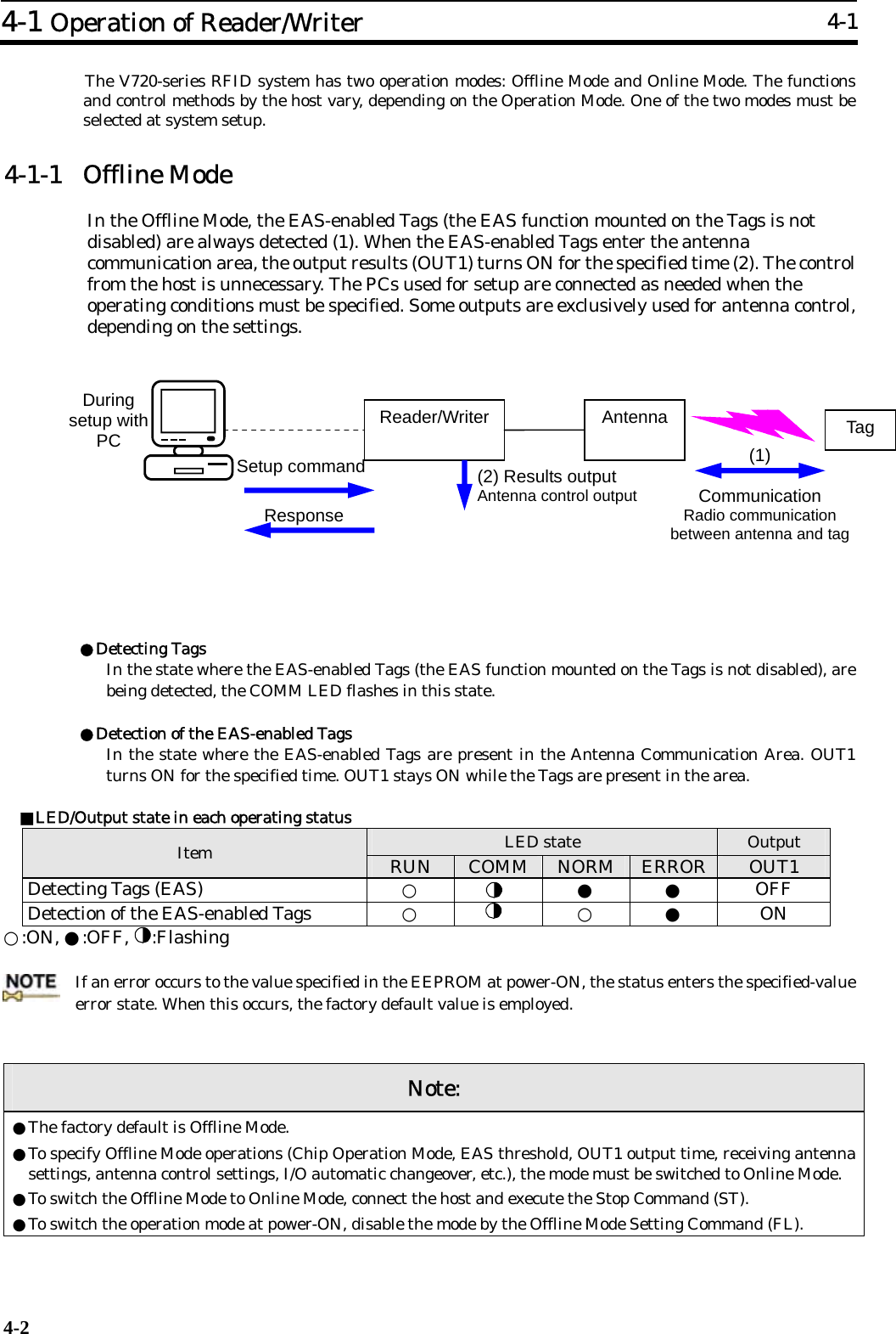
![3-1 SECTION 3 Functions 3-1 Operating Mode.................................................................................................. 3-2 3-1-1 Chip Operating Mode..........................................................................................3-2 3-1-2 Online Mode/Offline Mode...............................................................................3-2 3-2 Communication Modes.......................................................................................3-3 3-2-1 Single Access .......................................................................................................3-3 3-2-2 FIFO Access.........................................................................................................3-3 3-2-3 Multiple Access....................................................................................................3-4 3-2-4 Selective Access...................................................................................................3-4 3-2-5 Fast Read Access: I.CODE1 Mode only .............................................................3-5 3-3 Memory Check Function: I.CODE1 Mode Only................................................ 3-6 3-3-1 Usage...................................................................................................................3-6 3-4 Lock Function.....................................................................................................3-7 3-5 Discriminating Access to Tag Function.............................................................3-8 3-6 External I/O Function........................................................................................ 3-9 3-6-1 External Input......................................................................................................3-9 3-6-2 External Output ...................................................................................................3-9 3-7 EAS Function..................................................................................................... 3-10 3-8 Duplicate Communication Protecting Function [Ver1.20 or higher]................ 3-11](https://usermanual.wiki/Omron-RFID-Business-Development-Department/V720SBC5D4A-US/User-Guide-710365-Page-32.png)
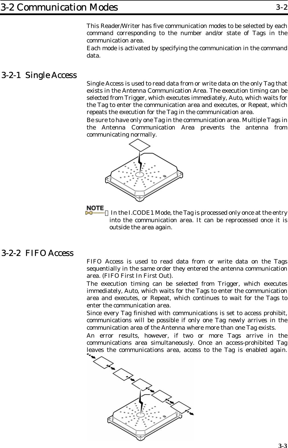
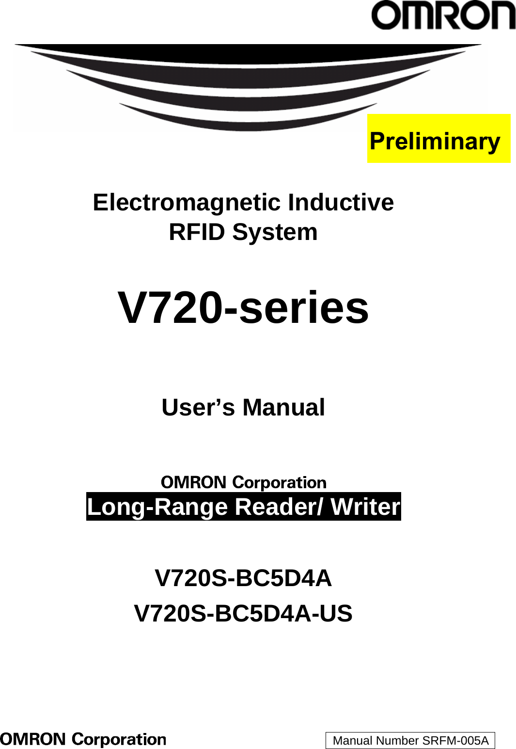
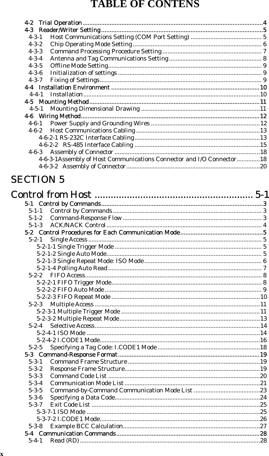
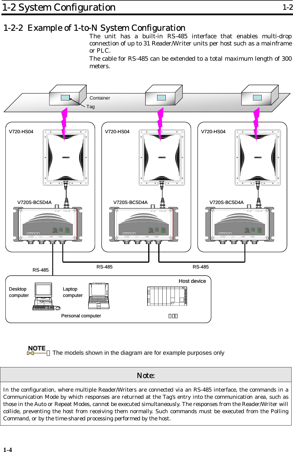
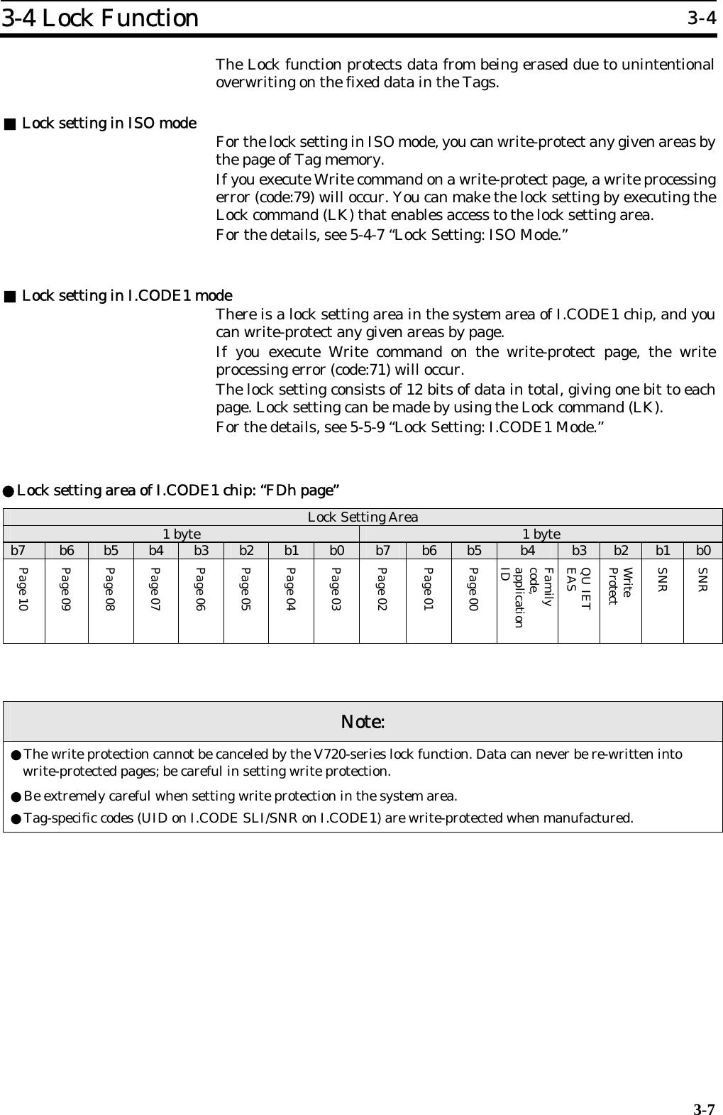
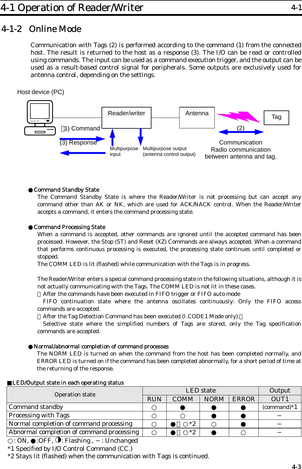
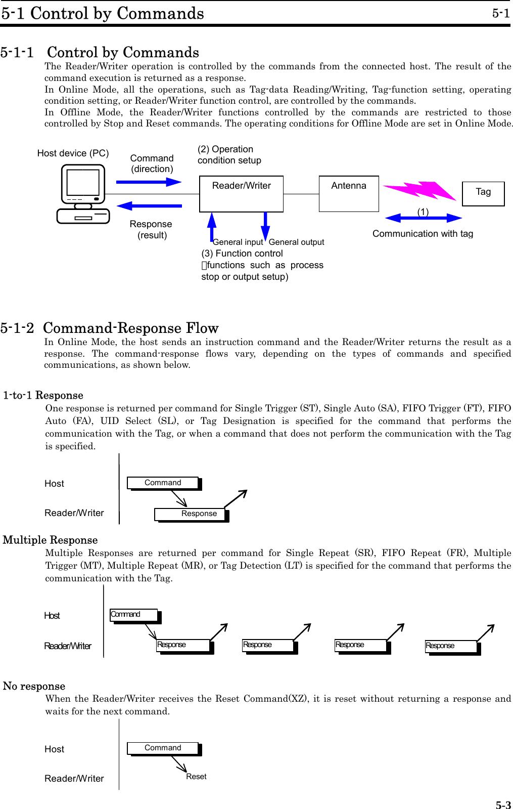
![3-2 Communication Modes 3-2 3-5 3-2-5 Fast Read Access: I.CODE1 Mode Only The Fast Read Access speeds up the data readout in I.CODE1 Mode. The execution timing can be selected from Trigger, which executes immediately, Auto, which waits for the Tag to enter the communication area and executes, or Repeat, which repeats the execution for the Tag in the communication area. The function operates the same way as in Single Access mode when the Tag number code is set to 0; in other cases it is the same as in Multiple Access Mode. [When the Tag number code is set to 0 (Single Access Mode)] By selecting the Trigger or Auto execution timing, the function executes the same operation as that in normal single access mode but in a shorter period of time. When the Repeat execution timing is selected, the function continuously returns data while the Tags are present in the communication area, this is useful in confirming the communication area. [When the Tag number code is set to those other than 0 (Multiple Access Mode)] The only execution timing available is Repeat, since the function employs a simple version of the communication sequence, some Tag data may be unreadable under the condition where the responses from the Tags collide frequently. In addition, the function processes and responds to the same Tags repeatedly while they are present in the communication area. This function should be used when there is a low number of Tags in the communication area. When there are a greater number of Tags, the Multiple Access Mode should be used. The Duplicate Communication Protecting Function is useful to avoid multiple responses returned to the same Tag. (Refer to SECTION 3-8). Note: ●For the I.CODE1 Communication Modes used under the conditions, where Multiple Tags exit in the Antenna Communication Area (Multiple Access, Selective Access, or Fast Read Modes), the Tag Number Code must be specified. The maximum number of Tags allowed in the communications area is set previously. (Refer to SECTION 5-2-5 for details).](https://usermanual.wiki/Omron-RFID-Business-Development-Department/V720SBC5D4A-US/User-Guide-710365-Page-36.png)
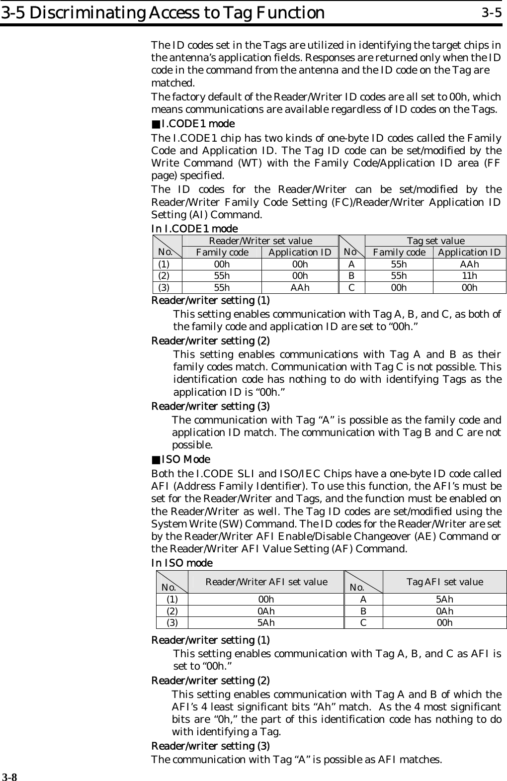
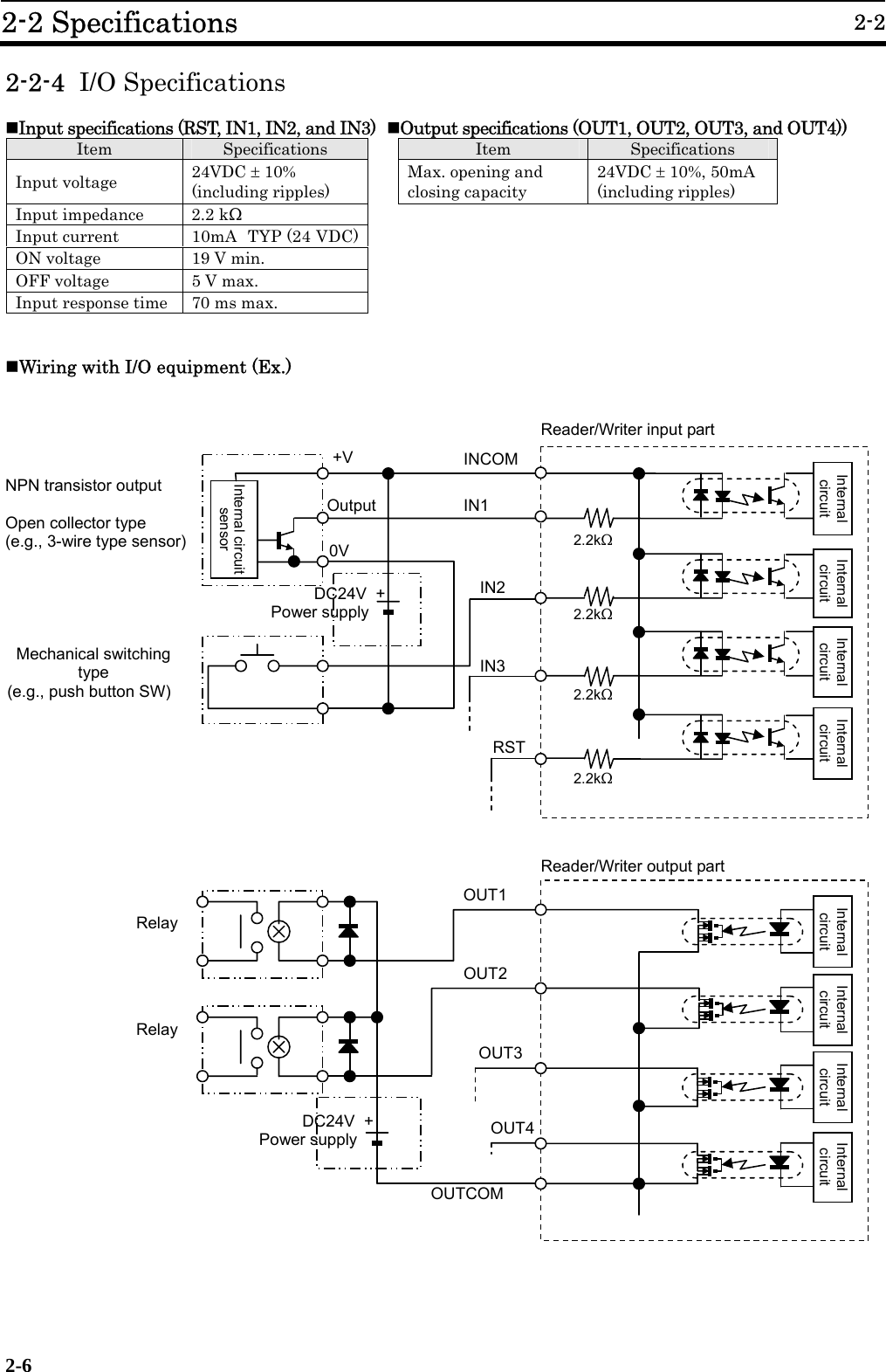
![3-6 External I/O Function 3-6 3-9 The I/O connector has three external input ports and four external output ports to which such devices as sensors or actuators are connected to build a more efficient system. The external output may be dedicated to the antenna control, depending on the Reader/Writer settings. 3-6-1 External Input [Online Mode] The status can be obtained by the I/O Control Command (CC). Sequenced operations such as those for starting and terminating the communication with Tags by external triggers are available. [Offline Mode] Not available. The I/O Control Command (CC) is rejected. To perform the function, the mode must be switched to the Online Mode by the Stop Command (ST). 3-6-2 External Output [Online Mode] The output status can be modified or read-out by the I/O Control Command (CC.) Read-out data can be evaluated by the host and output as a control signal for Lamps or sounds. When the I/O Automatic Changeover Setting is enabled, the external outputs 3 (OUT3) and 4 (OUT4) are dedicated to the antenna control and thus unmodifiable. However, the output status can be read-out. [Offline Mode] The external output is dedicated to the control from the Reader/Writer in this mode. Modification/Reading out of the output status by the I/O Control Command (CC) is unavailable. The external output 1 (OUT1) is turned ON for a specified period of time (modifiable) when Tags with the uncanceled EAS is detected. The external outputs 3 (OUT3) and 4 (OUT4) are dedicated to antenna control when the I/O Automatic Changeover setting is enabled.](https://usermanual.wiki/Omron-RFID-Business-Development-Department/V720SBC5D4A-US/User-Guide-710365-Page-40.png)
![3-7 EAS Function 3-7 3-10 The Reader/Writer supports the EAS (Electronic Article Surveillance) system applied for anti-theft and other devices. The Reader/Writer identifies the unique data string returned by the EAS-bit enabled Tags and detects the existence of the Tags in the communication area. Multiple EAS-bit enabled Tags that exist simultaneously can also be detected. The Reader/Writer stops detecting the Tags by disabling the EAS bit on the Tags. This is useful in preventing unauthorized removal of properties or giving caution. The function operates in either Online Mode, where the function is executed by the commands issued by the connected host, or Offline Mode where the function is executed by the Reader/Writer alone. [Offline Mode] In the Offline Mode, the EAS-bit enabled (non-disabled) Tags are continuously detected. When the EAS-bit enabled Tags enter the Antenna Communication Area and their EAS-response concordance rate exceeds the specified value (=EAS threshold), the external output 1 (OUT1) will turn ON for the specified time. The operation state is visibly identified by the OUT1 LED light. The EAS threshold and external output time are specified by the Offline Mode Setting (FL) Command. ●EAS threshold The Tags return 256-bit fixed data. The concordance rate at which the Tag is recognized as one with non-disabled EAS (EAS-bit disable processing is not performed) is specified by a percentage. The smaller the concordance rate, the more lax the criteria becomes. The initial threshold is 75%. ●The ON-time of the external output 1 (OUT1) The ON-time is specified according to the output time of the lamp or buzzer. The initial output time is 500ms. [Online Mode] The EAS Check (EA) Command is executed from the host. (Refer to SECTION 5-5-10). The EAS-response concordance rate is returned, which is compared to the threshold in the host and evaluated for the existence of the EAS-enabled Tags. ■EAS Setting for the Tag The EAS on the Tag is enabled by a specific command that enables EAS-bit. For the ISO/IEC chip (I.CODE SLI chip), it is done by the System Write (SW) Command and for I.CODE1 chip, it is done by the EAS Setting (ES) Command.](https://usermanual.wiki/Omron-RFID-Business-Development-Department/V720SBC5D4A-US/User-Guide-710365-Page-41.png)
![3-8 Duplicate Communication Protecting Function 3-8 3-11 The Duplicate Communication Protecting Function prevents the command that processes multiple Tags serially from performing multiple Read/Write processing for each Tag. This function controls the command so that it performs the processing only once per Tag and returns a single response, even in situations where a Tag is recognized more than once as shown below. The processing load is reduced because the response receiving or duplication check by the host is unnecessary. The communication performance speed is also improved since unnecessary processing is eliminated in the following: 1. The situation where the Tag enters the Antenna Communication Area several times due to its vibration, irregular operation, or stop on the boundary, or because the Tag is in the antenna’s side lobe area. 2. The situation where the Tag is stopped in the boundary zone or enters the Antenna Communication Area several times because of the moved antenna. 3. The situation where the Tag passes an antenna with a discontinuous communication area such as the gate antenna. The enabled function is activated when the commands using the following communication modes are executed: ・FIFO Repeat Mode (FR) ・Multiple Trigger Mode (MT) ・Multiple Repeat Mode (MR, UR[I.CODE1 Only]*) When the function is enabled, the unique number (UID/SNR) given to the processed Tag is recorded in the table of the processed Tags after the command has been executed. When a new Tag is detected and its UID/SNR is obtained, the system refers to the table and processes the Tag only when the UID/SNR is not found in the table. After the Tag has been processed normally, the system records the UID/SNR in the table. The table is initialized at the start of command. * As to UR, the page on which the processing is started must be FB, and the pages must be 2 and more. The function is set by the Duplicate Communication Protecting Function Setting (MX) Command (disabled by factory default.) To enable the function, specify the maximum number of UID/SNRs recorded in the table of the processed Tags. The number of tables can be selected from 1, 4, 8, 16, 64, 128, or 256. Usually, the closest number above the maximum number of Tags that can co-exist in the communication area of the antenna being used is specified. Example) When the maximum number of the co-existing Tags are 6: The number of tables = 8 0 1: Tag0 2: Tag1 3: Tag2 4: Tag3 5: (Vacant) 6: (Vacant) 7: (Vacant) 8: (Vacant) 4The table of the processed Tags:In this case, Tag 0 is not processed for re-entry in the communication area. When the Tag 4 enters the area it is processed and recorded in row 5: of the table.](https://usermanual.wiki/Omron-RFID-Business-Development-Department/V720SBC5D4A-US/User-Guide-710365-Page-42.png)
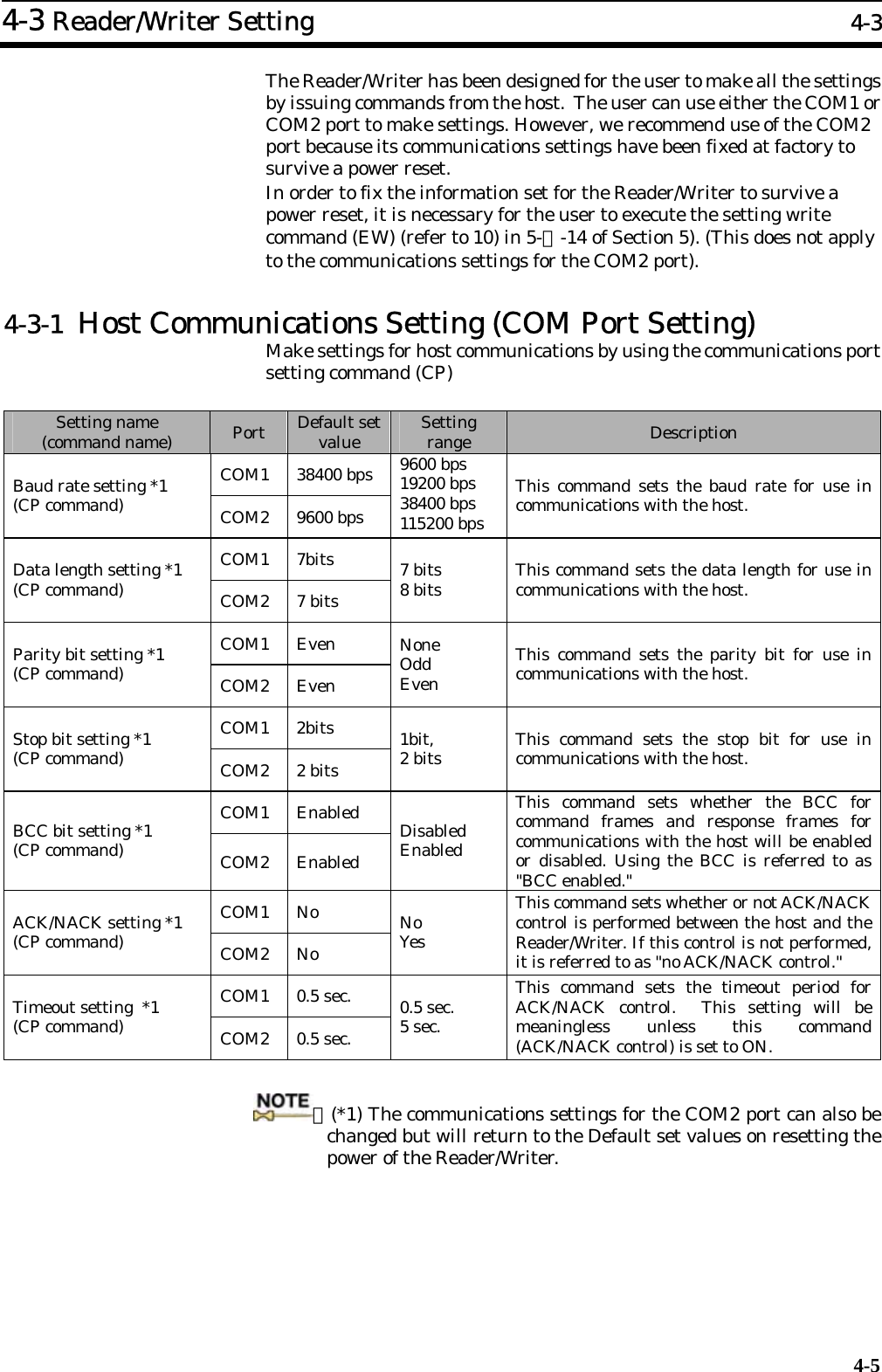
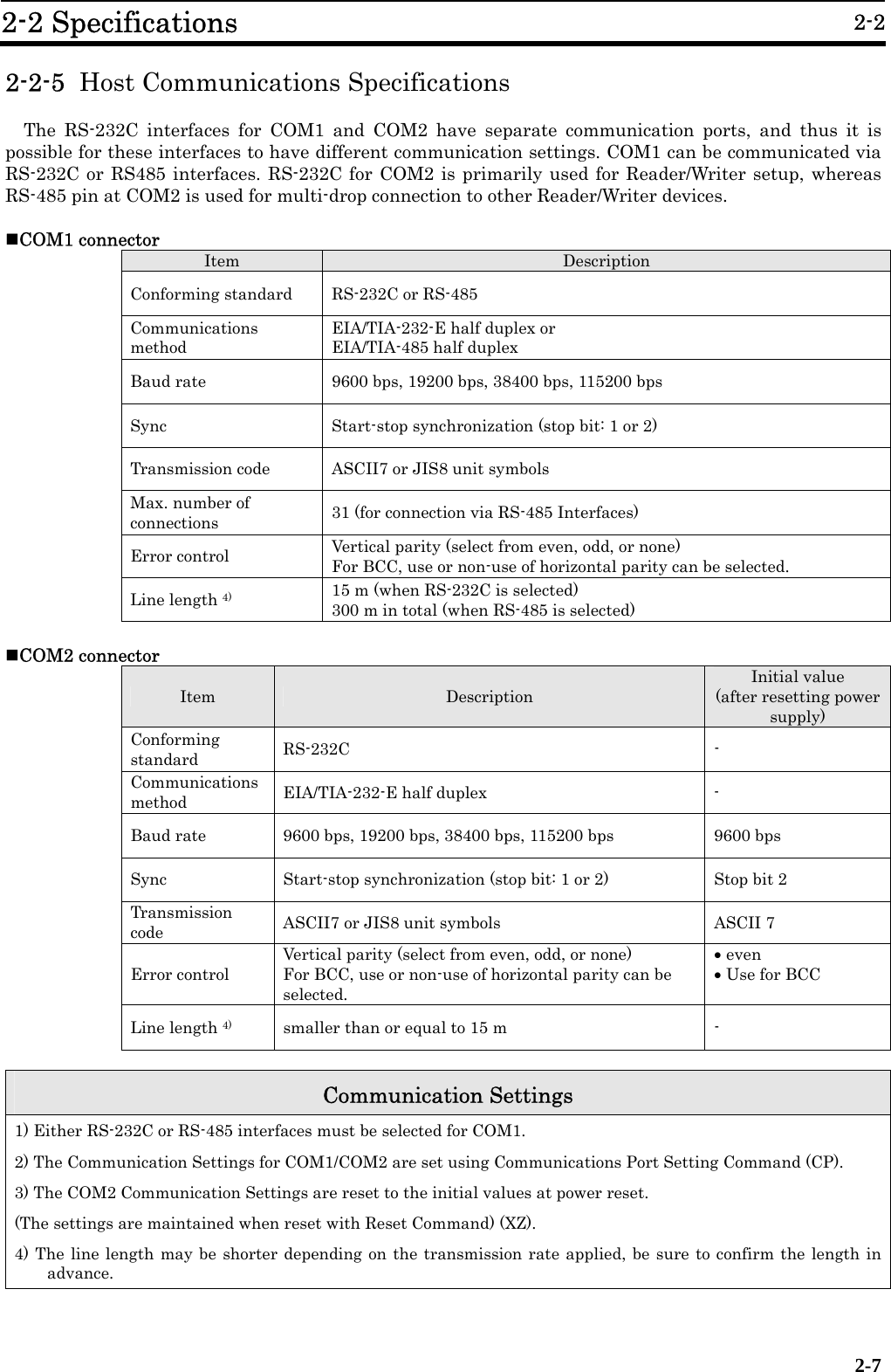
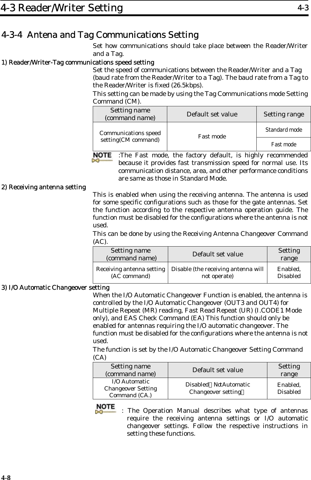
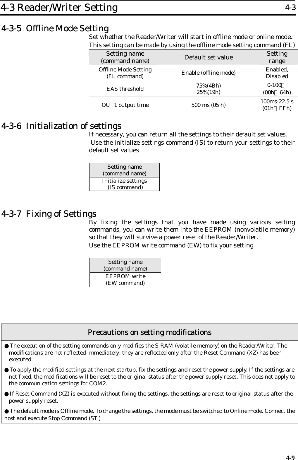
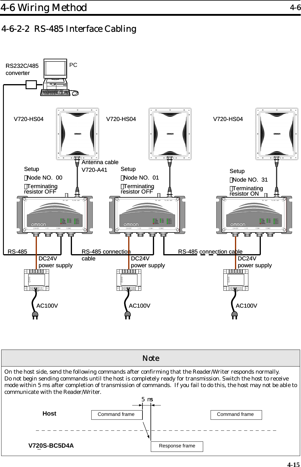
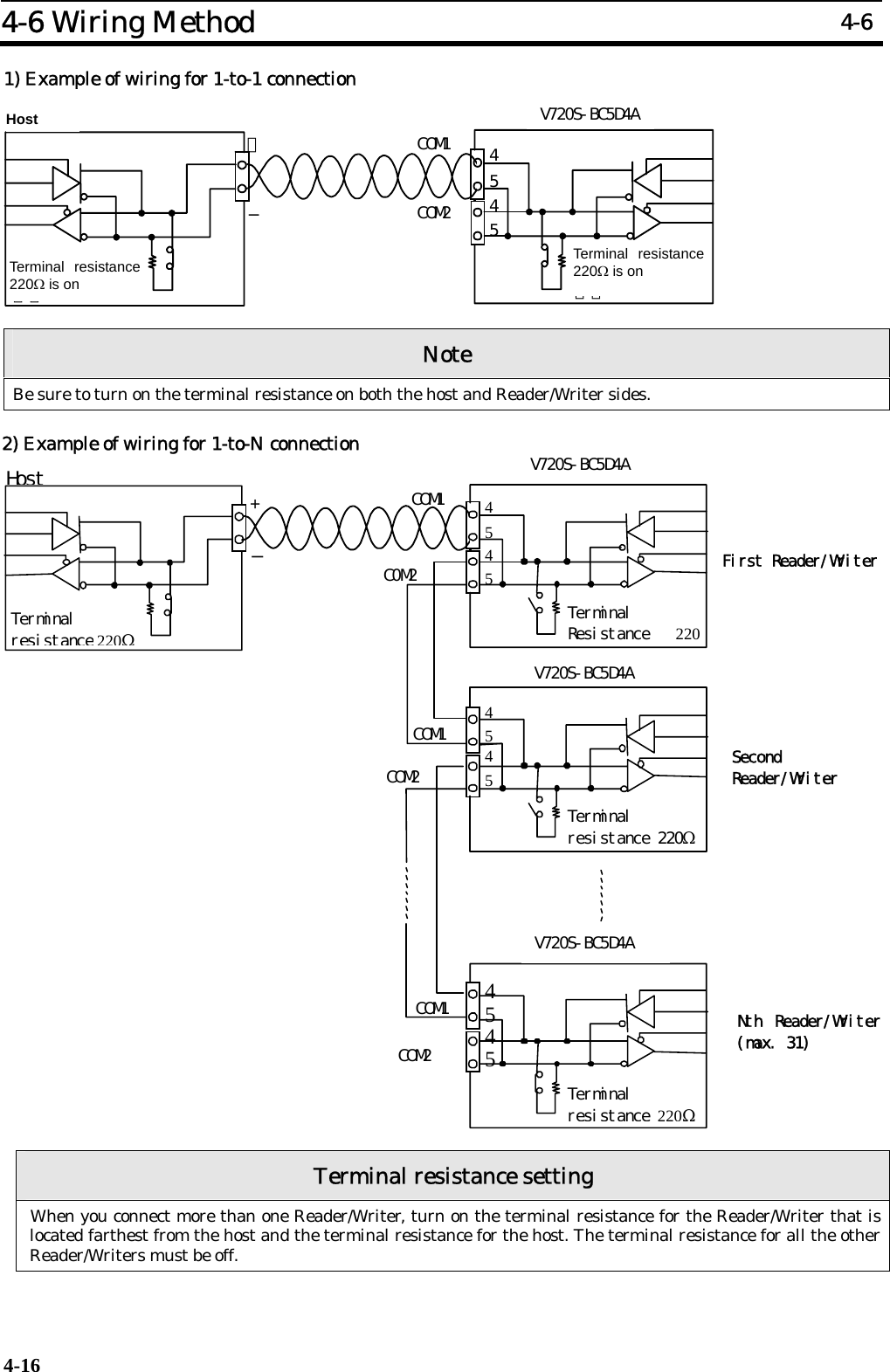
![4-3 Reader/Writer Setting 4-3 4-6 1) Communications type setting for COM1 port Set whether COM1 will be used as RS-232C or RS-485 by using the communications type setting command (CT) Setting name (command name) Default set value Setting range Communications type setting *1 (CT command) RS-232C RS-232C RS-485 2) Node No. setting If more than one Reader/Writer is connected to a single host, each Reader/Writer needs an ID number so that the host can discriminate one Reader/Writer from another. Such an ID number is called node number. Each Reader/Writer must be assigned a unique node number. Each command or response includes the node number of the Reader/Writer. Communications will not be possible if the node number is wrong. The setting can be saved by executing the setting write command. Use the node number setting command (NM) to set a node number. Setting name (command name) Default set value Setting range Node No. setting (NM command) 00 00∼31 :Communications through COM2 are possible regardless of the node number setting. 3) Terminal resistance setting This setting is necessary when COM1 is used as RS-485. If more than one Reader/Writer is connected to a single host, terminal resistance must be turned on for both the host and the Reader/Writer connected to either end of the host in order to ensure stable operation. The setting can be saved by executing the setting write command. Use the terminal resistance setting command (TM) to set the terminal resistance. Setting name (command name) Default set value Setting range Terminal resistance setting (TM command) OFF ON/OFF : For more information, refer to 4-6-2-2 RS-485 Interface Cabling. 4-3-2 Chip Operating Mode Setting This Reader/Writer consists of 2 types of operating modes (hereinafter called: Operating Mode) in accordance with a type of the Tag (an incorporated IC chip). Both operating modes must be set in accordance with the Tag you choose. Execute the Operating Mode Switch Setting Command (TY). Setting name (command name) Default set value Setting range Remarks ISO Mode Conformed to the ISO/IEC15693 standard (I.CODE SLI Chip) Operating Mode Switch Setting Command (TY))ISO Mode [1.20 - ]* I.CODE1 Mode [ - 1.10] I.CODE1 Mode I.CODE1 Chip supported](https://usermanual.wiki/Omron-RFID-Business-Development-Department/V720SBC5D4A-US/User-Guide-710365-Page-48.png)
![4-3 Reader/Writer Setting 4-3 4-7 4-3-3 Command Processing Procedure Setting 1)UID/SNR Addition Setting For the Read command response in I.CODE1 Mode or the Read/Write command response in ISO Mode, whether to add the UID/SNR (a serial number which is a unique ID given to a Tag) must be selected. When enabled, this command makes association of data contained in a Tag to the serial number of that Tag considerably easier. Make this setting by using the UID/SNR Addition Command (SN) Setting name (command name) Default set value Setting range UID/ SNR addition setting(SN command))Disable (do not add) Enabled, Disabled :Note Using Selective Access in ISO Mode when communicating with specific Tags among the multiple Tags in the communication area is extremely useful, because data reading and UID acquisition can be processed by a single command. 2)Discriminating Access to Tag Setting The discriminating access to the Tags is set using the AFI (ISO Mode) on the Tags or the Family Code/Application ID (I.CODE1 Mode.) Refer to SECTION 3-5 for the details of the function. The settings are done using the specific setting command of each operating-mode. Operating mode Setting name (command name) Default set value Setting range Reader/Writer AFI Enable/Disable Changeover (AE Command) Disabled Enabled, Disabled ISO Reader/Writer AFI Value Setting (AF Command) 00 00∼FFh Reader/Writer Family Code Setting (FC Command) 00 00∼FFh I.CODE1 Reader/Writer Application ID setting (AI Command) 00 00∼FFh 3)Duplicate Communication Protecting Function In executing the commands with the options that specify the serial processing of multiple Tags (FR, MT, MR, and UR [I.CODE1 Mode]), the function controls the condition so that the Tags with the same UID/SNR are processed only once. This function is enabled by specifying the maximum number for the table of the processed Tags. Refer to SECTION 3-8 for the details of the function. This function is specified by the Duplicate Communication Protecting Function Setting Command (MX.) Setting name (command name) Default set value Setting range Mask Setting (MX Command) Disabled Enabled (The number of tables: 1, 4, 8, 16, 32, 64, 128, 256), Disabled](https://usermanual.wiki/Omron-RFID-Business-Development-Department/V720SBC5D4A-US/User-Guide-710365-Page-49.png)
![5-2 5-5-3 System Lock (SL): ISO Mode only..................................................................... 5-42 5-5-4 Read (RD)-SNR Read: I.CODE1 Mode only...................................................... 5-43 5-5-5 EAS Setting (ES): I.CODE1 Mode only ............................................................ 5-44 5-5-6 QuietBit Setting (QB): I.CODE1 Mode only..................................................... 5-44 5-5-7 Lock Setting (LK): ISO Mode............................................................................. 5-45 5-5-8 Lock Setting Read (LR): ISO Mode only ........................................................... 5-46 5-5-9 Lock Setting (LK): I.CODE1 Mode.................................................................... 5-47 5-5-10 EAS Check (EA).................................................................................................. 5-48 5-6 Reader/Writer Control Commands....................................................................... 5-49 5-6-1 Stop (ST) ............................................................................................................. 5-49 5-6-2 Reset (XZ)............................................................................................................ 5-49 5-6-3 ACK (AK) ............................................................................................................ 5-49 5-6-4 NACK (NK)......................................................................................................... 5-49 5-6-5 I/O Control Command (CC) ............................................................................... 5-50 5-6-6 Test (TS).............................................................................................................. 5-50 5-6-7 Version (VS)........................................................................................................ 5-51 5-7 Setting Command ................................................................................................. 5-52 5-7-1 Reader/Writer AFI Enable/Disable Changeover (AE): ISO Mode only........... 5-52 5-7-2 Reader/Writer AFI Value setting (AF): ISO Mode only................................... 5-52 5-7-3 Reader/Writer Family Code Setting (FC): I.CODE1 Mode.............................. 5-53 5-7-4 Reader/Writer Application ID Setting (AI): I.CODE1 Mode ........................... 5-53 5-7-5 UID/SNR Addition Setting (SN)........................................................................ 5-54 5-7-6 Node Number Setting (NN) ............................................................................... 5-55 5-7-7 Communications Port Setting (CP)................................................................... 5-56 5-7-8 Communications Type Setting (CT).................................................................. 5-58 5-7-9 Tag Communications Mode Setting (CM)......................................................... 5-58 5-7-10 Antenna Changeover (AC) ................................................................................. 5-59 5-7-11 Terminal Resistance Setting (TM) .................................................................... 5-59 5-7-12 Offline Mode Setting (FL) .................................................................................. 5-60 5-7-13 Set Value Initialization (IS)............................................................................... 5-61 5-7-14 Set Value Writing (EW) ..................................................................................... 5-61 5-7-15 Chip Operating Mode Switch (TY) .................................................................... 5-62 5-7-16 Duplicate Communication Protecting Function Setting (MX) [Ver1.20 and higher] .. 5-63 5-7-17 I/O Automatic Changeover Setting (CA) [Ver1.20 and higher]....................... 5-64 5-8 Other Commands .................................................................................................. 5-65 5-8-1 Command Undefined Response......................................................................... 5-65 5-9 Command Connection: I.CODE1 Mode only.............................................................. 5-67](https://usermanual.wiki/Omron-RFID-Business-Development-Department/V720SBC5D4A-US/User-Guide-710365-Page-63.png)

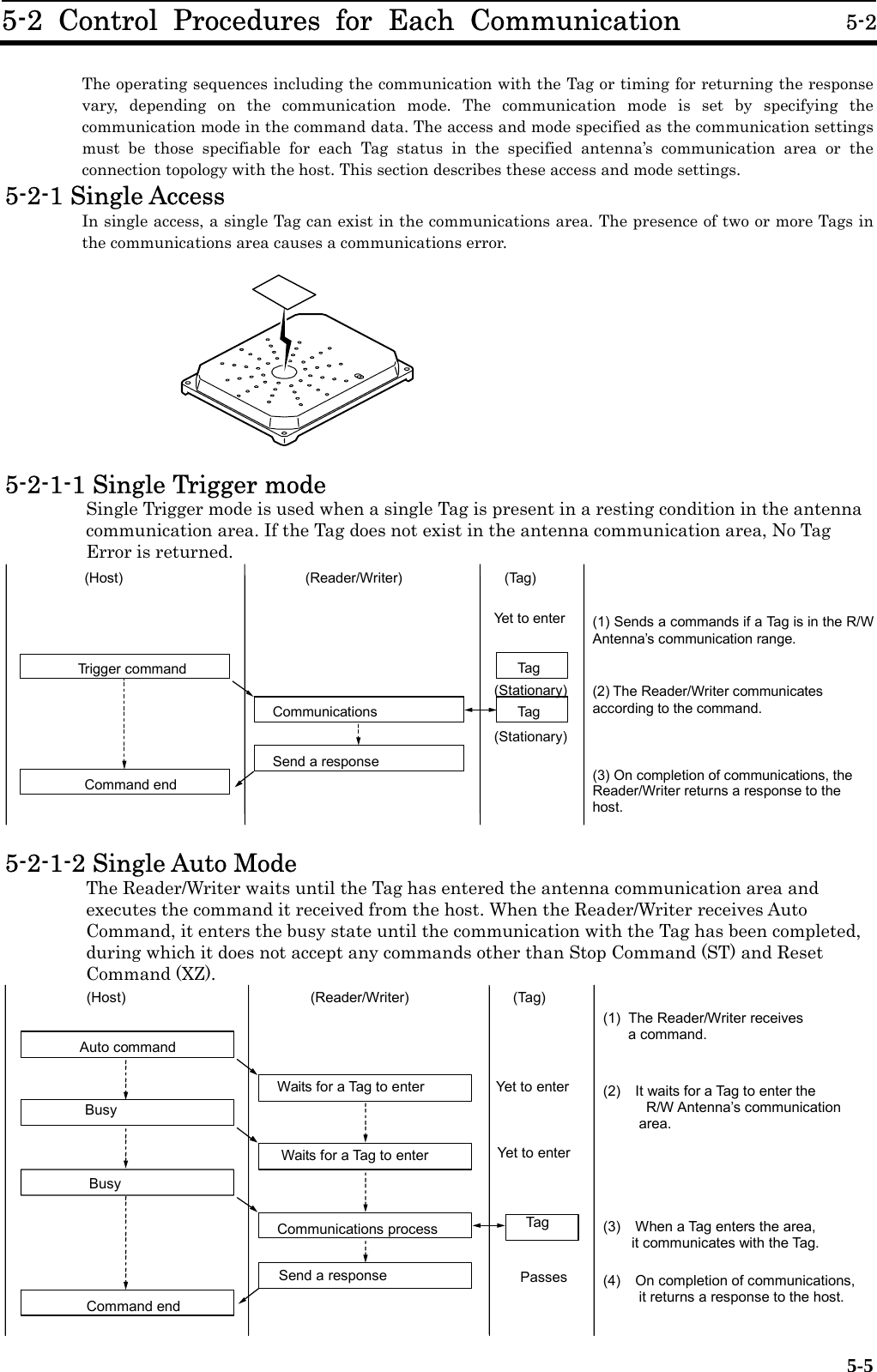
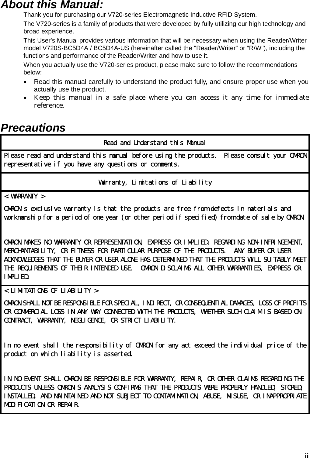
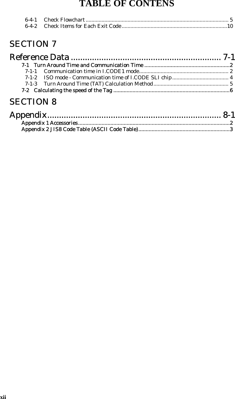
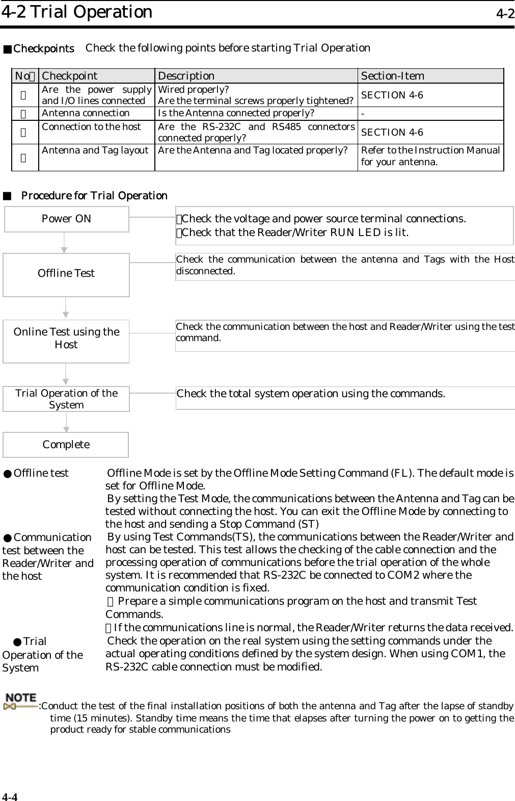
![5-2 Control Procedures for Each Communication 5-2 5-10 5-2-2-3 FIFO Repeat Mode The Reader/Writer waits until the Tag has entered the antenna communication area and starts communicating. It communicates with the Tags serially as they enter the antenna communication area, and returns the responses. When the communication has been completed, the Reader/Writer makes the Tag inaccessible, so that it can communicate with the next Tag that entered the area although the Tags with which the Reader/Writer has completed the communication are still present in the same area. This state continues until the communication has been terminated by Stop Command (ST), or Reset Command (XZ), and other commands are rejected. タグ接近待ち タグ接近待ち タグ接近待ち 交信処理 レスポンス タグ接近待ち レスポンス受信 リピートコマンド ビジー状態 ビジー状態 ビジー状態 未接近(上位機器) (リーダライタ) (タグ)①R/W アンテナの交信領域内にタグが入るのを待ちます。 ②タグが R/W アンテナの交信領域内に入るとリーダライタはタグと交信を行います。③交信が終了するとレスポンスを返信します。 その後、再度 R/W アンテナの交信領域内にタグが入るのを待ちます。 ④再度タグが R/W アンテナの交信領域内に入ると交信を行います。 交信処理 タグ(1)タグ(2)ビジー状態 ビジー状態 レスポンス 未接近 通過 未接近 通過 未接近 レスポンス受信 When the Tag is on the boundary of the communication area or enters the communication area more than once because of swing, the Tag may be processed more than once, or some Tags may not be processed. In this case, enable the Duplicate Communication Protecting Function (Table number = 1). The function will prevent the Reader/Writer from communicating with the Tags already communicated with, and allows proper and sequential Tag processing.[Software Ver 1.20 and higher only] Note To send another command from Repeat Mode, be sure to use either the stop command or reset command, and make sure that the Reader/Writer has finished processing commands and is in command waiting status before sending the new command. Waits for a Tag to approachWaits for a Tag to approachCommunication process Response Receives a response Waits for a Tag to approachRepeat Command Busy Busy Busy Busy Receives a response Busy Waits for a Tag to approachCommunication process Response (Host) (Reader/Writer) (Tag) (1) Waits for a Tag to enter the Reader/Writer antenna communication area. (2)When a Tag enters the Reader/Writer antenna communication area, the Reader/Writer communicates with the Tag. (3)When the communication has been completed, the Reader/Writer returns a response. Then it waits for the next Tag to enter the Reader/Writer antenna communication area. (4) When the next Tag enters the Reader/Writer antenna communication area, the Reader/Writer communicates with the Tag. Tag (1)Tag (2)PassesPassesYet to approach Yet to approach Yet to approach Yet to approach](https://usermanual.wiki/Omron-RFID-Business-Development-Department/V720SBC5D4A-US/User-Guide-710365-Page-71.png)
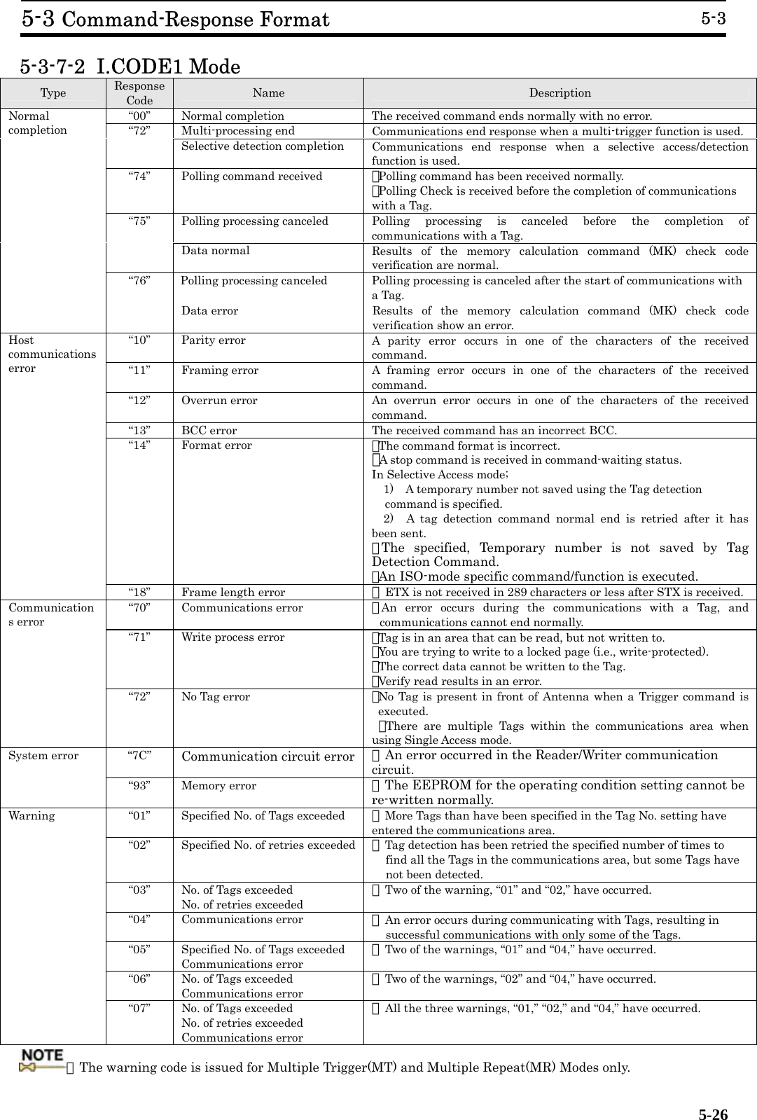
![5-3 Command-Response Format 5-3 5-25 5-3-7 Response Code List 5-3-7-1 ISO Mode Type Response Code Name Description “00” Normal completion The received command ends normally with no error. “72” Multi-processing end Communications end response when a multi-trigger function is used. “74” Polling command received ・Polling command has been received normally. ・Polling Check is received before the completion of communications with a Tag. “75” Polling processing canceled Polling processing is canceled before the completion of communications with a Tag. Normal completion “76” Polling processing canceled Polling processing is canceled after the start of communications with a Tag. “10” Parity error A parity error occurs in one of the characters of the received command. “11” Framing error A framing error occurs in one of the characters of the received command. “12” Overrun error An overrun error occurs in one of the characters of the received command. “13” BCC error The received command has an incorrect BCC. “14” Format error ・The command format is incorrect. ・A stop command is received in command-waiting status. ・An I.CODE1-mode specific command/function is executed. Host communications error “18” Frame length error ・ETX is not received in 289 characters or less after STX is received. “70” Communications error ・An error occurs during the communications with a Tag, and communications cannot end normally. “71” Write process error ・Failed to write correct data onto a Tag. (Verification error) ・An error occurred in the data writing process between a Tag, preventing the process from being completed normally. “72” No Tag error ・No Tag is present in front of Antenna when a Trigger command is executed. ・There are multiple Tags within the communications area when using Single Access mode. “79” Command error ・ Refer to the correlation table of ISO/IEC Error Codes. “7A” Address error ・Unavailable pages. (ISO/IEC standard error code 10) *Results in 79 error on I.CODE SLIs because the Tag is not supported. Communications error “7E” Lock error [ver1.20 and higher] ・Writing onto a locked page. (ISO/IEC standard error code 12) *Results in 79 error on I.CODE SLIs because the Tag is not supported. “7C” Communication circuit error ・An error occurred in the Reader/Writer communication circuit. System error “93” Memory error ・The EEPROM for the operating condition setting cannot be re-written normally. ■ Correlation table of ISO/IEC Error Codes When a Tag incorporating ISO/IEC chip (including I.CODE SLI chip) returns an error response, the Reader/Writer responses a Response Code shown in the table below. ISO code Description Response code of module01 An unadopted command. No request command can be recognized. 79 02 An unrecognizable command. ex. format error. 79 03 An unadopted arbitrary command 79 0F An unaccountable error or unadopted error code. 79 10 A specific block cannot be use. (There is none) 7A 11 A specific block cannot be relocked since the block has been already locked. 00 12 A specific block cannot be rewritten since it is locked. 71/7E 13 A specific block has not completed writing correctly. 71 14 A specific block has not completed locking correctly. 71 Others RFU 79](https://usermanual.wiki/Omron-RFID-Business-Development-Department/V720SBC5D4A-US/User-Guide-710365-Page-86.png)
![5-5 System Command 5-5 5-48 5-5-10 EAS Check (EA) This command transmits the EAS command continuously and returns the percentage of data that matches the EAS response code. <Command Format> 1)In ISO mode STX Node No.. Command code “EA” Tag type ETX BCC1 2 2 1 1 1 2)In I.CODE1 mode STX Node No.. Command code “EA” ETX BCC1 2 2 1 1 Tag type (ISO mode) Specifies Tag type. A: I.CODE SLI chip * Not added in I.CODE1 mode. <Response Format> STX Node No.. Retry flag Command code “EA” Response code “00” Ratio ETX BCC1 2 1 2 2 2 1 1 Response code 00:normal completion For other Response Codes, refer to SECTION 5-3-7 Response Code List. Ratio Indicates the ratio of data that matches the EAS response code in hexadecimal. (00h to 64h[%]) How to use properly 1) In some cases, this command will not indicate 0% even though there are no Tags. Be sure take this into account when determining the presence or absence of Tags. 2) The EAS Check Command works as a repeat command. After this command is sent once, only a response will be returned. To discontinue transmission of this command, you need to use the Stop Command (refer to ST Command in 5-6-1).](https://usermanual.wiki/Omron-RFID-Business-Development-Department/V720SBC5D4A-US/User-Guide-710365-Page-109.png)
![5-7 Setting Command 5-7 5-63 5-7-16 Duplicate Communication Protecting Function setting (MX) This command specifies the enabled/disabled state of the duplicate communication protecting function and the number of tables in the enabled state. When the function is enabled, the Tag is read only once at the execution of a command with FIFO Repeat (FR), Multiple Trigger, or Multiple Repeat (MR, UR [I.CODE1 mode]) options. Refer to SECTION 3-8 for the details of the function. <Command format> STX Node No. Command code MX” Number of tablesExtension“0” ETX BCC1 2 2 1 1 1 1 Specifies the enabled/disabled state of the duplicate communication protecting function and the number of tables used to record UID/SNR in the enabled state. Specifying 0 for the number of tables disables the function. Specification range: 0 to 8 (Factory default: 0 - disabled) When * is specified, the currently specified value is read. Value “0” “1” “2” “3” “4” “5” “6” “7” “8” Number of tables Specified number Disabled1 4 8 16 32 64 128 256 Extension The number specified for an extension, always specify 0. <Response Format> STX Node No. Retry Flag Command code MX” Response Code 00 Number of tablesExtension“0” ETX BCC1 2 1 2 2 1 1 1 1 Response Code 00:Normal completion For other Response Codes, refer to SECTION 5-3-7 Response Code List. Number of tables Number of tables specified extension. Extension The Extension number specified 0 is always returned. :・The setting is enabled after reset by the Reset Command. To enable the setting at the next start-up, the setting must be saved by Set Value Writing command (EW). ・For the number of tables, specify the closest number above the maximum number of Tags that coesxist in the communication area of the antenna used. ・In executing the command in I.CODE1 Mode with UR option, fix FB for the start page, and specify the number 2 and greater for the number of pages. Specifying other than thsese values results in command error (Code: 14). Example: To read the pages from FB to 01, [STX]00RDURH2FB07[ETX][BCC]](https://usermanual.wiki/Omron-RFID-Business-Development-Department/V720SBC5D4A-US/User-Guide-710365-Page-124.png)
![5-7 Setting Command 5-7 5-64 5-7-17 I/O Automatic Changeover setting (CA) This function alternately turns the output terminals (OUT3 and OUT4) ON and OFF for Multiple Repeat and EAS. Check commands every time the command is issued. This is used to switch multiple antennas automatically. Enable the function when a special antenna that requires this function is used. Otherwise, disable the function. <Command Format> STX Node No. Command code CA” Output ETX BCC1 2 2 1 1 1 Specifies the enabled/disabled state of the output signal. Specification range: 0,1, (Factory default: 0) When * is specified, the currently specified value is read. Specified number 0 1 * Output Disabled Enabled - <Response Format> STX Node No. Retry flag Command code CA” Response Code 00 Output ETX BCC1 2 1 2 2 1 1 1 Response Code 00:Normal Completion For other Response Codes, refer to SECTION 5-3-7 Response Code List. Output Output value Displays the specified output value. :・The setting is enabled after reset by the Reset Command. To enable the setting at the next start-up, the setting must be saved by Set Value Writing (EW). ・Alternately, the OUT3 and OUT4 on the Reader/Writer are turned ON and OFF. ・This function is applied only for Multiple Repeat read and EAS check (and offline EAS check) command in ISO mode, and EAS check (and offline EAS check) command in I.CODE1 Mode. The function is not activated by other commands. ・When the function is enabled, the control of OUT3 and OUT4 by I/O Control Command (CC) is unavailable. To control OUT1 and OUT2, specify * for the OUT3 and OUT4 values. Example) When OUT1:ON, OUT2:OFF, Note No. 00 [STX]00CC10**[ETX][BCC]](https://usermanual.wiki/Omron-RFID-Business-Development-Department/V720SBC5D4A-US/User-Guide-710365-Page-125.png)
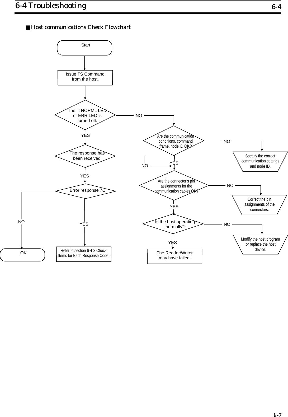
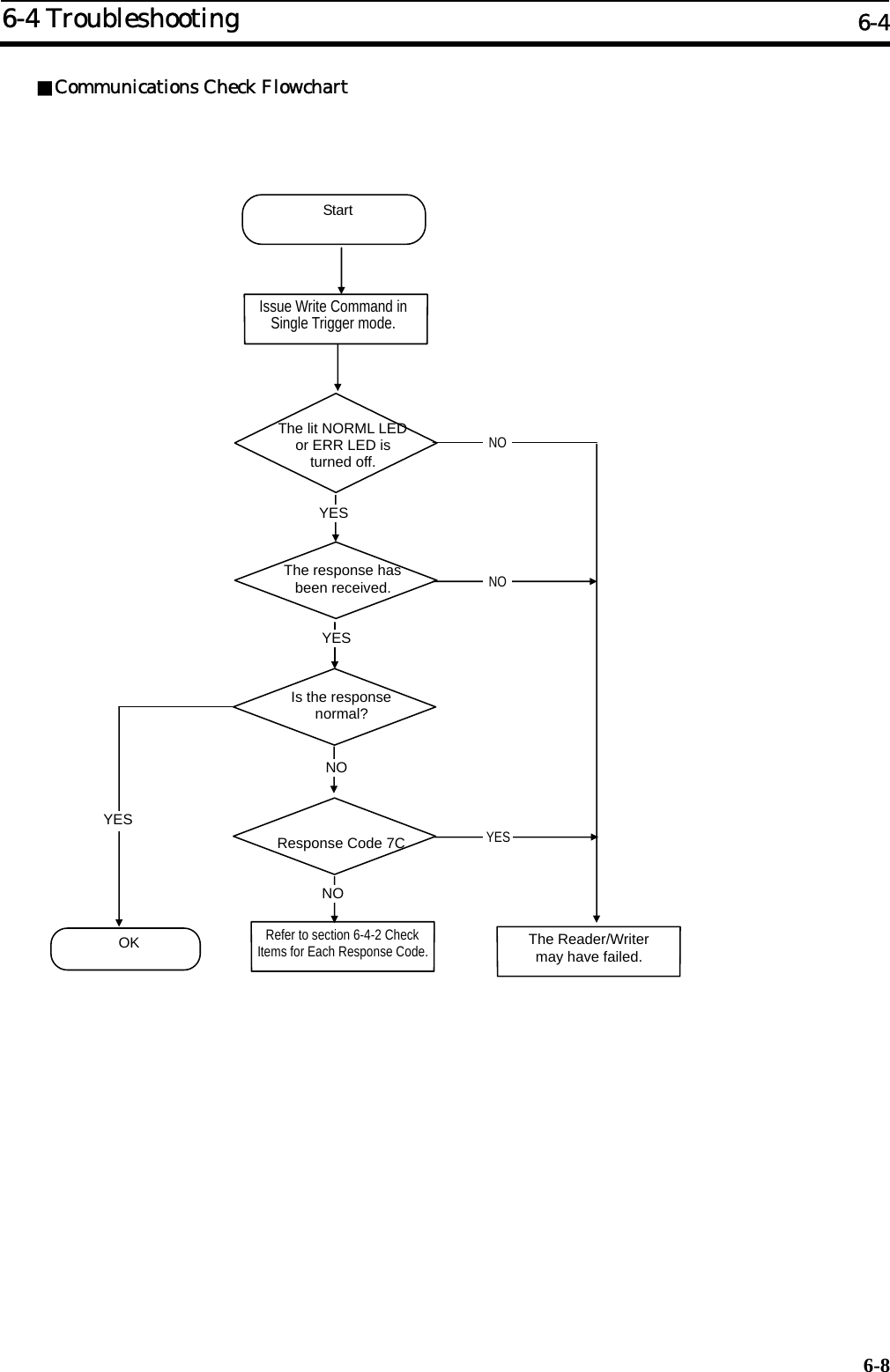
![6-4 Troubleshooting 6-4 6-106-4-2 Check Items for Each Response Code Response Code Primary check items (Nonresponding state) ・Are the communication conditions set for the host and the Reader/Writer matched? Transmission rate, data length, stop bit length, parity (even, odd, none) ・Is the control code (STX/ETX) transmitted properly? ・Are the command node No. and Reader/Writer node No. setting matched? ・Is the Reader/Writer set to Offline mode? ・Is the command issued by the Reader/Writer executable in the state? Offline mode: Commands are not accepted. Communication with the Tag in progress: Commands are not accepted. FIFO mode: Only FIFO Access command is accepted. Select state: Only Tag Designation command is accepted. *Stop Command (ST) and Reset Command (XZ) are always executable. ・Is the command issued during the initialization (approximately 2.5 seconds) that follows power ON or Reset Command execution? 10 11 12 ・Are the communication conditions set for the host and the Reader/Writer matched? Transmission rate, data length, stop bit length, parity (even, odd, none) ・Is there a noise source near the communication cables? 13 ・Is the added BCC correct? Calculation method, Format (Binary,1byte) 14 ・Is data for each command field correct? Communication method specified (Types, combination with the commands), specified data, Tag types, page, written data ・Is the command executable with the Reader/Writer’s chip operating mode (I.CODE1/ISO) settings? ・Is the simplified number already assigned using Tag designation command? [I.CODE1 Mode] 18 ・Is the command to be issued correct? ・Is the control code (STX/ETX) transmitted correctly? 70 ・Aren’t there multiple Tags present in the communication area? [In Single Access mode] ・Is there any antennas other than the one communicating, nearby? ・Are there any devices or cables that could be a source of noise nearby? ・Is the Tag in the stable communication area? ・Does the Tag stay for a short time in the communication area? (Is it moving fast enough?) ・Is the specified page within the Tag’s memory range? ・Does the Reader/Writer support the Tag? 71 ・Is the Tag re-written exceeding its rewrite cycle? ・Is the write target page locked? [In ICODE1 Mode] ・Does the Reader/Writer support the Tag? 72 ・Is the communication distance between the antenna and Tag appropriate? ・Are there multiple Tags present in the communication area? ・Are chip operating mode and the type of Tag used matched? ・Does the Reader/Writer support the Tag? 79 ・Is the specified page within the Tag’s memory range? [ISO mode - I.CODE SLI] ・Is the write target page locked? [ISO Mode - I.CODE SLI] 7A ・Is the specified page within the Tag’s memory range? [ISO mode] 7C ・If this occurs continuously, the Reader/Writer may fail. 7E ・Is the specified page locked? [ISO Mode] (IC) ・The command code for the command is incorrect.](https://usermanual.wiki/Omron-RFID-Business-Development-Department/V720SBC5D4A-US/User-Guide-710365-Page-138.png)
![Appendix 2 JIS8 Code Table (ASCII Code Table) 8-3 High Order Low Order b8 - b5 0000 0001 0010 0011 0100 0101 0110 0111 b4 - b1 Colum Row 0 1 2 3 4 5 6 7 0000 0 NUL TC7(DLE) (SP) 0 @ P ` p 0001 1 TC1(SOH) DC1 ! 1 A Q a q 0010 2 TC2(STX) DC2 " 2 B R b r 0011 3 TC3(ETX) DC3 # 3 C S c s 0100 4 TC4(EOT) DC4 $ 4 D T d t 0101 5 TC5(NEQ) TC8(NAK) % 5 E U e 0110 6 TC6(ACK) TC9(SYN) & 6 F V f v 0111 7 BEL TC10(ETB) ' 7 G W g w 1000 8 FE0(BS) CAN ( 8 H X h x 1001 9 FE1(HT) EM ) 9 I Y i y 1010 10 FE2(LF) SUB * : J Z j z 1011 11 FE3(VT) ESC + ; K [ k { 1100 12 FE4(FF) IS4(FS) , < L \ l | 1101 13 FE5(CR) IS3(GS) - = M ] m } 1110 14 S0 IS2(RS) . > N ^ n ~ 1111 15 S1 IS1(US) / ? O _ o DEL :The ASCII code character for the fifth row, line 12 is “ “.](https://usermanual.wiki/Omron-RFID-Business-Development-Department/V720SBC5D4A-US/User-Guide-710365-Page-147.png)