Omron RFID Business Development Department V720SBC5D4A-US RF ID Reader User Manual
Omron Corporation, RFID Business Development Department RF ID Reader
user manual

Electromagnetic Inductive
RFID System
V720-series
User’s Manual
Long-Range Reader/ Writer
V720S-BC5D4A
V720S-BC5D4A-US
Manual Number SRFM-005A
Preliminary

ii
About this Manual:
Thank you for purchasing our V720-series Electromagnetic Inductive RFID System.
The V720-series is a family of products that were developed by fully utilizing our high technology and
broad experience.
This User’s Manual provides various information that will be necessary when using the Reader/Writer
model V720S-BC5D4A / BC5D4A-US (hereinafter called the "Reader/Writer” or “R/W"), including the
functions and performance of the Reader/Writer and how to use it.
When you actually use the V720-series product, please make sure to follow the recommendations
below:
• Read this manual carefully to understand the product fully, and ensure proper use when you
actually use the product.
• Keep this manual in a safe place where you can access it any time for immediate
reference.
Precautions
Read and Understand this Manual
Please read and understand this manual before using the products. Please consult your OMRON
representative if you have any questions or comments.
Warranty, Limitations of Liability
< WARRANTY >
OMRON's exclusive warranty is that the products are free from defects in materials and
workmanship for a period of one year (or other period if specified) from date of sale by OMRON.
OMRON MAKES NO WARRANTY OR REPRESENTATION, EXPRESS OR IMPLIED, REGARDING NON-INFRINGEMENT,
MERCHANTABILITY, OR FITNESS FOR PARTICULAR PURPOSE OF THE PRODUCTS. ANY BUYER OR USER
ACKNOWLEDGES THAT THE BUYER OR USER ALONE HAS DETERMINED THAT THE PRODUCTS WILL SUITABLY MEET
THE REQUIREMENTS OF THEIR INTENDED USE. OMRON DISCLAIMS ALL OTHER WARRANTIES, EXPRESS OR
IMPLIED.
< LIMITATIONS OF LIABILITY >
OMRON SHALL NOT BE RESPONSIBLE FOR SPECIAL, INDIRECT, OR CONSEQUENTIAL DAMAGES, LOSS OF PROFITS
OR COMMERCIAL LOSS IN ANY WAY CONNECTED WITH THE PRODUCTS, WHETHER SUCH CLAIM IS BASED ON
CONTRACT, WARRANTY, NEGLIGENCE, OR STRICT LIABILITY.
In no event shall the responsibility of OMRON for any act exceed the individual price of the
product on which liability is asserted.
IN NO EVENT SHALL OMRON BE RESPONSIBLE FOR WARRANTY, REPAIR, OR OTHER CLAIMS REGARDING THE
PRODUCTS UNLESS OMRON'S ANALYSIS CONFIRMS THAT THE PRODUCTS WERE PROPERLY HANDLED, STORED,
INSTALLED, AND MAINTAINED AND NOT SUBJECT TO CONTAMINATION, ABUSE, MISUSE, OR INAPPROPRIATE
MODIFICATION OR REPAIR.

iii
Application Considerations
< SUITABILITY FOR USE >
OMRON shall not be responsible for conformity with any standards, codes, or regulations that
apply to the combination of the products in the customer's application or use of the products.
At the customer's request, OMRON will provide applicable third party certification documents
identifying ratings and limitations of use that apply to the products. This information by
itself is not sufficient for a complete determination of the suitability of the products in
combination with the end product, machine, system, or other application or use.
The following are some examples of applications for which particular attention must be given.
This is not intended to be an exhaustive list of all possible uses of the products, nor is it
intended to imply that the uses listed may be suitable for the products:
z Outdoor use, uses involving potential chemical contamination or electrical interference,
or conditions or uses not described in this manual.
z Nuclear energy control systems, combustion systems, railroad systems, aviation systems,
medical equipment, amusement machines, vehicles, safety equipment, and installations
subject to separate industry or government regulations.
z Systems, machines, and equipment that could present a risk to life or property.
Please know and observe all prohibitions of use applicable to the products.
NEVER USE THE PRODUCTS FOR AN APPLICATION INVOLVING SERIOUS RISK TO LIFE OR PROPERTY WITHOUT
ENSURING THAT THE SYSTEM AS A WHOLE HAS BEEN DESIGNED TO ADDRESS THE RISKS, AND THAT THE OMRON
PRODUCTS ARE PROPERLY RATED AND INSTALLED FOR THE INTENDED USE WITHIN THE OVERALL EQUIPMENT
OR SYSTEM.
< PROGRAMMABLE PRODUCTS >
OMRON shall not be responsible for the user's programming of a programmable product, or any
consequence thereof.
Disclaimers
< PERFORMANCE DATA >
Performance data given in this manual is provided as a guide for the user in determining
suitability and does not constitute a warranty. It may represent the result of OMRON’s test
conditions, and the users must correlate it to actual application requirements. Actual
performance is subject to the OMRON Warranty and Limitations of Liability.
< CHANGE IN SPECIFICATIONS >
Product specifications and accessories may be changed at any time based on improvements and
other reasons.

iv
It is our practice to change model numbers when published ratings or features are changed, or
when significant construction changes are made. However, some specifications of the products
may be changed without any notice. When in doubt, special model numbers may be assigned to
fix or establish key specifications for your application on your request. Please consult with
your OMRON representative at any time to confirm actual specifications of purchased products.
< DIMENSIONS AND WEIGHTS >
Dimensions and weights are nominal and are not to be used for manufacturing purposes, even when
tolerances are shown.
< ERRORS AND OMISSIONS >
The information in this manual has been carefully checked and is believed to be accurate; however,
no responsibility is assumed for clerical, typographical, or proofreading errors, or omissions.
v
Safety Precautions
This chapter provides important information for the safe use of this product.
Ensure to read the information carefully before use.
In the safety precautions below, severity is categorized as either ”WARNING” or “CAUTION”.
WARNING
Indicates a potentially hazardous situation which, if not avoided,
could result in death or serious injury.
Caution Indicates a potentially hazardous situation which, if not avoided,
may result in minor or moderate injury, or property damage.
Property damage refers to extended damage caused to
house/household goods or livestock/pets.
●Description of Symbols
Prohibition
Indicates an action or activity not permitted.
Observe strictly
Indicates the need to ensure the safe use of the product.
Ensure to establish a solid grounding
A label indicating that a device with a grounding terminal should always be
grounded.
Electric shock hazard
A notification that alerts the possibility of electric shock under certain
conditions.
Do not disassemble
A notification that prohibits disassembly when injuries caused by electric
shocks may result.
Please ensure that all cautions and prohibitions are adhered to, since non-compliance may lead
to serious injury or damage, in certain circumstances.
vi
WARNING
Never disassemble, repair, or modify the main unit and cables.
z Do not disassemble, repair, or modify this product. Doing so may result in electric shock, fire, or
personal injury.
Do not handle the device with wet hands. Do not touch the terminals while the
device is connected to the power supply.
z Electric shock hazard.
Do not allow the cables to be in contact with heaters.
z The cable sheaths may melt and the exposed wire may cause electric shock or fire.
Be sure a solid grounding is established for the device.
z Electric shock hazard.
Caution
Do not drop the device or apply physical shock.
z Doing so may result in personal injury or device damage.
Do not apply strong force to, or place heavy items on the device or cables.
z Doing so may deform or damage the device, resulting in electric shock or fire.
Use and store the product in an environment that is specified in the catalog or
operation manual.
z Failure to do so may cause failure of the device, electric shock, or fire. Do not use or store the
device in the following locations:
・ Locations that do not satisfy the specified operating conditions (-10 to +50℃, 35%RH to
85%RH,non-condensing).
・ Locations that do not satisfy the specified storage conditions (-25 to +65℃, 35%RH to
85%RH,non-condensing).
・ Locations where the Reader/Writer is exposed to direct sunlight.
・ Locations where the Reader/Writer is exposed to dust, corrosive gas, saline, or flammable
gas.
・ Locations where the Reader/Writer is exposed to direct heat.
・ Locations subject to condensation due to high humidity.
・ Locations subject to vibration or impact that exceed the limits outlined in the
specifications.
・ Locations where the device may be exposed to water, oil, or chemical agents. (This
applies to the models other than waterproof types.)
・ Outdoor
Be sure to tighten the base-mounting and terminal-block screws securely.
z Failure to do so may result in personal injury or device damage.
Use the specified-sized distribution cables.
z Failure to do so may cause failure of the device, electric shock, or fire.
vii
Cables with locking attachments must be secured before use.
z Failure to do so may damage the device.
The specifications of the DC power unit used must satisfy all of the following
conditions:
・
The power unit must be connected to the V720-series system and must not be connected to any
other devices.
・The supply voltage for the power unit must be within the range specified in this document (within
the range of DC24V + 10% and – 10%).
・Observe correct polarity when connecting the power unit.
・Be sure a solid Class D grounding is established (former Class 3 grounding).
To avoid interferences with other systems, adhere to the following items and check
them before using the product.
z The product uses a publicly available ISM frequency band of 13.56 MHz to communicate with
Tags. Some transceivers, motors, monitoring devices, power supplies (power supply ICs), and
other similar RFID systems may generate noise, which cause radio interference and may affect
communication with Tags. If the product is required in the vicinity of these items, check for any
interferences prior to use.
z On the contrary, the system itself may affect radio station transmissions or medical devices. Be
cautious when using the system in the environments where such effects might occur.
z To minimize noise effects, adhere to the following:
・Establish a Class D grounding (former Class 3 grounding) for metal objects placed in the
vicinity of the system.
・Keep cables away from those with high voltages or heavy currents.
Do not allow the device or cables to be soused or exposed to water.
z Doing so may result in electric shock, fire or failure of non-waterproof devices or cables.
If the device fails or is exposed to water (non-waterproof devices or parts), or an
unusual smell, smoke, or sparks are detected, immediately refrain from using the
device and contact OMRON or a sales representative for service and repair.
z Continued use of the failed device may result in electric shock or fire.
Do not use damaged cables.
z Continued use of the damaged cables may result in electric shock or fire.

viii
Precautions
This chapter provides important information for international standards and copyright.
Ensure to read the information carefully before use.
V720-BC5D4A and V720-BC5D4A-US conform to the following laws and standards. This conformity is
effective only if V720-BC5D4A or V720-BC5D4A-US is used with the designated antenna, V720-HS04.
1) European Standards (R&TTE Directive)
This product will conform to the R&TTE Directive (Radio Equipment and Telecommunication
Terminal Equipment Directive) as a set of the antenna, V720-HS04 (in October 2006).
Radio : EN 300 330
EMC : EN 301 489-1(EN55024, EN61000-4-2,3,4,6)
Safety : EN61010 or 60950
2) FCC(USA):
This product conforms to FCC Part 15 Subpart C.
FCC ID: OZGV720SBC5D4A-US (V720S-BC5D4A-US only).
©Copyright OMRON Corporation 2005,2006. All rights reserved.
This document is protected by copyright and is intended solely for use in conjunction with the product.
Notify your OMRON representative before copying or reproducing this document in any manner, for any
other purpose.
Declarations
FCC WARNING
Changes or modifications not expressly approved by the party responsible for compliance could void the
user’s authority to operate the equipment.
NOTICE
This equipment has been tested and found to comply with the limits for a Class A digital device, pursuant to
part 15 of the FCC Rules. These limits are designed to provide reasonable protection against harmful
interference when the equipment is operated in a commercial environment.
This equipment generates, uses and can radiate radio frequency energy and, if not installed and used in
accordance with the instructions, may cause harmful interference to radio communications. Operation of
this equipment in a residential area is likely to cause harmful interference in which case the user will be
required to correct the interference at his own expense.
NOTICE
Attach the accompanying ferrite core to the cable of DC power supply at the side of AC Mains connected
with AC input and Ground terminal in order to meet FCC emission limits.
TABLE OF CONTENS
ix
SECTION 1
Features and System Configuration...............................1-1
1-1 Features.....................................................................................................................2
1-2 System Configuration................................................................................................ 3
1-2-1 Example of 1-to-1 System Configuration.............................................................3
1-2-2 Example of 1-to-N System Configuration............................................................4
SECTION 2
Specifications and Performance......................................2-1
2-1 Reader/Writer (V720S-BC5D4A)............................................................................. 2
2-1-1 Nomenclature......................................................................................................2
2-1-2 Names of Connector Terminals..........................................................................3
2-2 Specifications........................................................................................................... 4
2-2-1 General Specifications ........................................................................................4
2-2-2 Performance Specifications ................................................................................4
2-2-3 Reader/Writer Communications Specifications.................................................5
2-2-4 I/ O Specifications................................................................................................6
2-2-5 Host Communications Specifications.................................................................7
2-2-6 Dimensions..........................................................................................................8
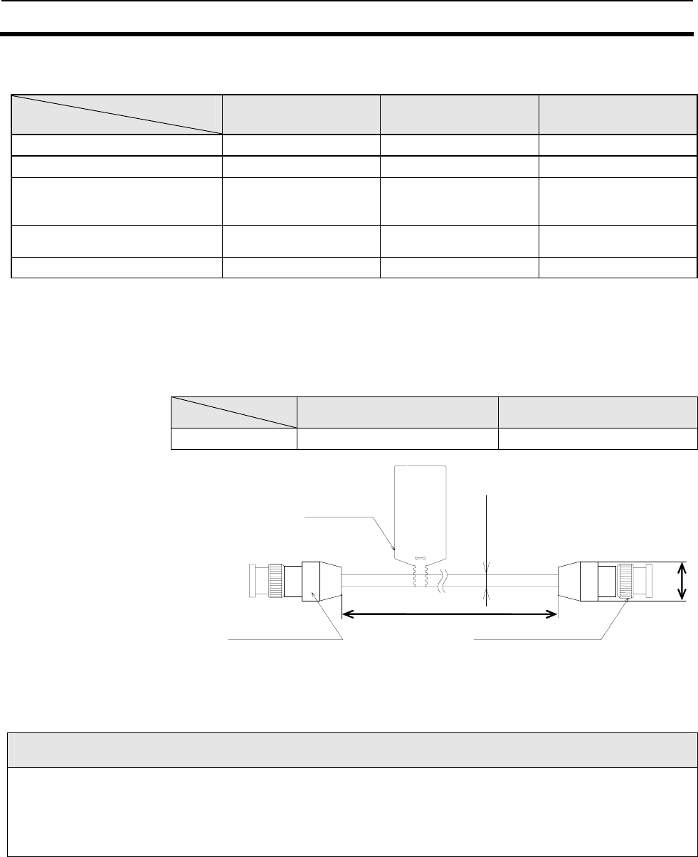
2-3 Cable (sold separately)...............................................................................................9
2-3-1 General Specifications ........................................................................................9
2-3-2 Dimensions..........................................................................................................9
2-4 Memory Map of Tag................................................................................................11
2-4-1 I.CODE SLI Chip .............................................................................................. 11
2-4-2 I.CODE1 Chip.................................................................................................... 14
SECTION 3
Functions..........................................................................3-1
3-1 Operating mode .........................................................................................................2
3-1-1 Chip Operating mode............................................................................................2
3-1-2 Online Mode/Offline Mode.................................................................................2
3-2 Communication Mode................................................................................................ 3
3-2-1 Single Access..........................................................................................................3
3-2-2 FIFO Access...........................................................................................................3
3-2-3 Multiple Access......................................................................................................4
3-2-4 Selective Access.....................................................................................................4
3-2-4 Fast Read Access: I.CODE1 Mode only ...............................................................5
3-3 Memory Check Function: I.CODE1 Mode only ........................................................6
3-3-1 Usage ...................................................................................................................6
3-4 Lock Function ............................................................................................................ 7
3-5 Discriminating Access to Tag Function.....................................................................8
3-6 External I/O Function ............................................................................................... 9
3-6-1 External Input.......................................................................................................9
3-6-2 External Output....................................................................................................9
3-7 EAS Function........................................................................................................... 10
3-8 Duplicate Communication Protecting Function .................................................... 11
SECTION 4
From Start-up to Operation.............................................4-1
4-1 Operation of Reader/Writer....................................................................................... 2
4-1-1 Offline Mode ..........................................................................................................2
4-1-2 Online Mode ..........................................................................................................3
TABLE OF CONTENS
x
4-2 Trial Operation...........................................................................................................4
4-3 Reader/Writer Setting................................................................................................5
4-3-1 Host Communications Setting (COM Port Setting) ........................................... 5
4-3-2 Chip Operating Mode Setting.............................................................................. 6
4-3-3 Command Processing Procedure Setting............................................................ 7
4-3-4 Antenna and Tag Communications Setting........................................................ 8
4-3-5 Offline Mode Setting............................................................................................. 9
4-3-6 Initialization of settings ....................................................................................... 9
4-3-7 Fixing of Settings.................................................................................................. 9
4-4 Installation Environment ........................................................................................10
4-4-1 Installation...........................................................................................................10
4-5 Mounting Method.....................................................................................................11
4-5-1 Mounting Dimensional Drawing ........................................................................11
4-6 Wiring Method..........................................................................................................12
4-6-1 Power Supply and Grounding Wires..................................................................12
4-6-2 Host Communications Cabling...........................................................................13
4-6-2-1 RS-232C Interface Cabling............................................................................13
4-6-2-2 RS-485 Interface Cabling ............................................................................15
4-6-3 Assembly of Connector ........................................................................................18
4-6-3-1Assembly of Host Communications Connector and I/O Connector..............18
4-6-3-2 Assembly of Connector.................................................................................20
SECTION 5
Control from Host ........................................................... 5-1
5-1 Control by Commands................................................................................................3
5-1-1 Control by Commands.......................................................................................... 3
5-1-2 Command-Response Flow .................................................................................... 3
5-1-3 ACK/NACK Control.............................................................................................. 4
5-2 Control Procedures for Each Communication Mode.................................................5
5-2-1 Single Access ......................................................................................................... 5
5-2-1-1 Single Trigger Mode ......................................................................................... 5
5-2-1-2 Single Auto Mode.............................................................................................. 5
5-2-1-3 Single Repeat Mode: ISO Mode....................................................................... 6
5-2-1-4 Polling Auto Read............................................................................................. 7
5-2-2 FIFO Access........................................................................................................... 8
5-2-2-1 FIFO Trigger Mode........................................................................................... 8
5-2-2-2 FIFO Auto Mode............................................................................................... 9
5-2-2-3 FIFO Repeat Mode..........................................................................................10
5-2-3 Multiple Access ....................................................................................................11
5-2-3-1 Multiple Trigger Mode ....................................................................................11
5-2-3-2 Multiple Repeat Mode.....................................................................................13
5-2-4 Selective Access....................................................................................................14
5-2-4-1 ISO Mode .........................................................................................................14
5-2-4-2 I.CODE1 Mode.................................................................................................16
5-2-5 Specifying a Tag Code: I.CODE1 Mode..............................................................18
5-3 Command-Response Format....................................................................................19
5-3-1 Command Frame Structure................................................................................19
5-3-2 Response Frame Structure..................................................................................19
5-3-3 Command Code List ............................................................................................20
5-3-4 Communication Mode List..................................................................................21
5-3-5 Command-by-Command Communication Mode List ........................................23
5-3-6 Specifying a Data Code........................................................................................24
5-3-7 Exit Code List ......................................................................................................25
5-3-7-1 ISO Mode .........................................................................................................25
5-3-7-2 I.CODE1 Mode.................................................................................................26
5-3-8 Example BCC Calculation...................................................................................27
5-4 Communication Commands.....................................................................................28
5-4-1 Read (RD).............................................................................................................28
TABLE OF CONTENS
xi
5-4-2 Write (WT)...........................................................................................................29
5-4-3 Read (RD)-Tag Detection: I.CODE1 Mode only.................................................31
5-4-4 Read (RD)-UID Select/Specified Tag..................................................................32
5-4-5 Write (WT)-UID Select/Specified Tag ................................................................33
5-4-6 Read (RD)-Fast Read Access: I.CODE1 Mode only...........................................34
5-4-7 Polling Single Auto Read (PR)............................................................................35
5-4-8 Polling Single Auto Write (PW)..........................................................................36
5-4-9 Polling Check (PC)..............................................................................................37
5-4-10 Polling End (PE)..................................................................................................38
5-4-11 Memory Check (MC): I.CODE1 Mode only........................................................39
5-4-12 Memory Calculation (MK): I.CODE1 Mode only ..............................................39
5-5 System Command.................................................................................................... 40
5-5-1 System Read (SR): ISO Mode only.....................................................................40
5-5-2 System Write (SW): ISO Mode only...................................................................41
5-5-3 System Lock (SL): ISO Mode only......................................................................42
5-5-4 Read (RD)-SNR Read: I.CODE1 Mode only ......................................................43
5-5-5 EAS Setting (ES): I.CODE1 Mode only .............................................................44
5-5-6 QuietBit Setting (QB): I.CODE1 Mode only......................................................44
5-5-7 Lock Setting (LK): ISO Mode .............................................................................45
5-5-8 Lock Setting Read (LR): ISO Mode only............................................................46
5-5-9 Lock Setting (LK): I.CODE1 Mode.....................................................................47
5-5-10 EAS Check (EA) ..................................................................................................48
5-6 Reader/Writer Control Commands.......................................................................... 49
5-6-1 Stop (ST)..............................................................................................................49
5-6-2 Reset (XZ) ............................................................................................................49
5-6-3 ACK (AK).............................................................................................................49
5-6-4 NACK (NK)..........................................................................................................49
5-6-5 I/O Control Command (CC)................................................................................50
5-6-6 Test (TS)...............................................................................................................50
5-6-7 Version (VS).........................................................................................................51
5-7 Setting Command.................................................................................................... 52
5-7-1 Reader/Writer AFI Enable/Disable Changeover (AE): ISO Mode only............52
5-7-2 Reader/Writer AFI Value setting (AF): ISO Mode only ....................................52
5-7-3 Reader/Writer Family Code Setting (FC): I.CODE1 Mode...............................53
5-7-4 Reader/Writer Application ID Setting (AI): I.CODE1 Mode ............................53
5-7-5 UID/SNR Addition Setting (SN).........................................................................54
5-7-6 Node Number Setting (NN)................................................................................55
5-7-7 Communications Port Setting (CP)....................................................................56
5-7-8 Communications Type Setting (CT)...................................................................58
5-7-9 Tag Communications Mode Setting (CM)..........................................................58
5-7-10 Antenna Changeover (AC)..................................................................................59
5-7-11 Terminal Resistance Setting (TM).....................................................................59
5-7-12 Offline Mode Setting (FL)...................................................................................60
5-7-13 Set Value Initialization (IS)................................................................................61
5-7-14 Set Value Writing (EW).......................................................................................61
5-7-15 Chip Operating Mode Switch (TY).....................................................................62
5-7-16 Duplicate Communication Protecting Function Setting (MX) [Ver1.20 and higher] 63
5-7-17 I/O Automatic Changeover Setting (CA) [Ver1.20 and higher]........................64
5-8 Other Commands..................................................................................................... 65
5-8-1 Command Undefined Response..........................................................................65
5-9 Command Connection: I.CODE1 Mode only........................................................... 66
SECTION 6
Startup and Full Operation.............................................6-1
6-1 Error Types and Diagnostic Functions.....................................................................2
6-2 Errors and Remedies................................................................................................. 3
6-3 Maintenance and Inspection..................................................................................... 4
6-4 Troubleshooting ......................................................................................................... 5
TABLE OF CONTENS
xii
6-4-1 Check Flowchart................................................................................................... 5
6-4-2 Check Items for Each Exit Code.........................................................................10
SECTION 7
Reference Data................................................................ 7-1
7-1 Turn Around Time and Communication Time ..........................................................2
7-1-1 Communication time in I.CODE1 mode.............................................................. 2
7-1-2 ISO mode - Communication time of I.CODE SLI chip....................................... 4
7-1-3 Turn Around Time (TAT) Calculation Method.................................................... 5
7-2 Calculating the speed of the Tag ...............................................................................6
SECTION 8
Appendix.......................................................................... 8-1
Appendix 1 Accessories.......................................................................................................2
Appendix 2 JIS8 Code Table (ASCII Code Table)..............................................................3
1-1
SECTION 1
Features and System Configuration
1-1 Features................................................................................................................ 1-2
1-2 System Configuration .......................................................................................... 1-3
1-2-1 Example of 1-to-1 System Configuration...........................................................1-3
1-2-2 Example of 1-to-N System Configuration..........................................................1-4
1-1 Features 1-2
1-2
The V720-series Electromagnetic Inductive RFID System is ideal for the construction of highly
functional, long-distance wireless ID systems for material control and logistics.
V720S-BC5D4A (hereinafter called “Reader/Writer”) is the device to communicate with Tag
(manufactured by OMRON) of the V720-series that use two kinds of I-CODE chips manufactured by
Philips Semiconductor (Product name: SL1 ICS30 01, Common name: I.CODE1; and Product name:
SL2 ICS20, Common name: I.CODE2). The chip SL2 ICS 20 is fully conforming to ISO/EC15693.
The Reader/Writer can be connected to personal computers (PCs) and Programmable Logic Controllers
(PLCs) to process large amounts of data flexibly with simple commands.
RU
N
CO
M
M
NO
RM
ER
RO
R
RUN
COMM
NORM
ERROR
+24V
GND
GR
Reset
IN1
IN2
IN3
INCOM
OUT1
OUT2
OUT3
OUT4
OUTCOM
COM1
EIA-485
COM2
EIA-232
COM1
EIA-232/485
Host Device for setup such
as PC or PLC.
RU
N
CO
M
M
NO
RM
ER
RO
R
RU
N
CO
M
M
NO
RM
ER
RO
R
RUN
COMM
NORM
ERROR
RUN
COMM
NORM
ERROR
+24V
GND
GR
Reset
IN1
IN2
IN3
INCOM
OUT1
OUT2
OUT3
OUT4
OUTCOM
COM1
EIA-485
COM2
EIA-232
COM1
EIA-232/485
Host Device for setup such
as PC or PLC.
■Highly Functional RFID System
In addition to 1-to-1 communication between a Tag and an
antenna, the RFID System operates in either multiple
simultaneous access mode, selective access mode, or FIFO
(first-in, first-out) read/write mode. In multiple simultaneous
access mode, if there is more than one Tag in the communications
area, the RFID System reads and writes data from and to all the
Tags at one time. In selective access mode, the user can specify the
Tags from and to which data is read and written. In FIFO
read/write mode, the RFID System reads and writes data to one
Tag after another as they come into the communications area.
■Support of off-line EAS Mode
The Reader/Writer can operate in EAS mode (see 3-7 in Section 3)
as a standalone device, with no need to connect with the host.
■I/O function
By issuing commands from the host, the user can operate three
input points and four output points.
■Protection Construction
The protection construction IP60 has been achieved in the
Reader/Writer.
1-2 System Configuration 1-2
1-3
1-2-1 Example of 1-to-1 System Configuration
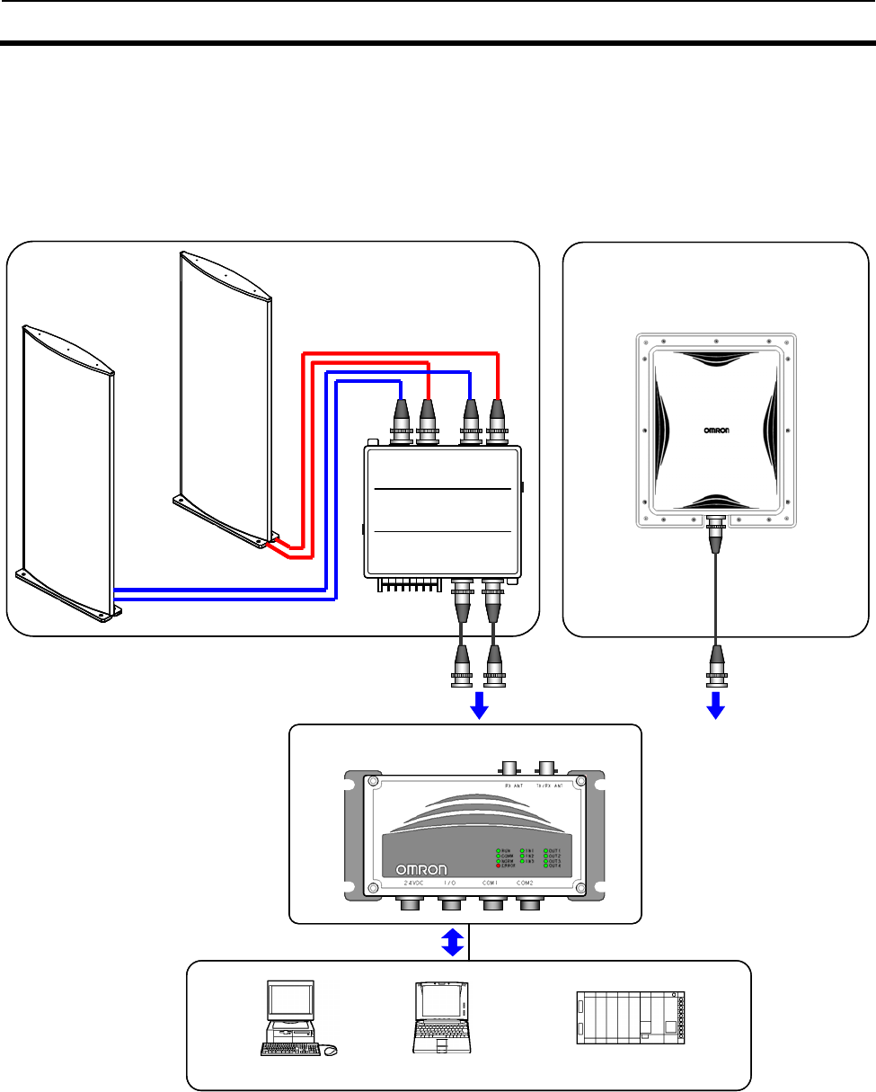
The V720S-BC5D4A has a built-in serial interface conforming to RS-232C
and RS-485, thus making it possible to communicate with personal
computers and PLCs. All the ordinary communication processes take
place via commands from the host.
RUN
COM
M
NORM
ERRO
R
ON
ON
Gate Antenna
V720-HS72
○
○
Rx_R Rx_C Tx/Rx_R
Tx/Rx_C
Rx_ANT
Tx/Rx_ANT
OMRON
V720-K70
RF SW BOX
Long-Range Reader/Writer
V720S-BC5D4A
Long-Range Antenna
V720-HS04
Personal computer PLC
Desktop
computer
Laptop
computer
RS-232C
Host
device
RUN
COM
M
NORM
ERRO
R
RUN
COM
M
NORM
ERRO
R
ONON
ONON
Gate Antenna
V720-HS72
○
○
Rx_R Rx_C Tx/Rx_R
Tx/Rx_C
Rx_ANT
Tx/Rx_ANT
OMRON
V720-K70
RF SW BOX
○
○
Rx_R Rx_C Tx/Rx_R
Tx/Rx_C
Rx_ANT
Tx/Rx_ANT
OMRON
V720-K70
RF SW BOX
○
○
Rx_R Rx_C Tx/Rx_R
Tx/Rx_C
Rx_ANT
Tx/Rx_ANT
○
○
Rx_R Rx_C Tx/Rx_R
Tx/Rx_C
Rx_ANT
Tx/Rx_ANT
OMRON
V720-K70
RF SW BOX
Long-Range Reader/Writer
V720S-BC5D4A
Long-Range Antenna
V720-HS04
Personal computer PLC
Desktop
computer
Laptop
computer
RS-232C
Host
device
1-2 System Configuration 1-2
1-4
1-2-2 Example of 1-to-N System Configuration
The unit has a built-in RS-485 interface that enables multi-drop
connection of up to 31 Reader/Writer units per host such as a mainframe
or PLC.
The cable for RS-485 can be extended to a total maximum length of 300
meters.
RUN
COM
M
NOR
M
ERR
OR
Personal computer PLC
Desktop
computer
Laptop
computer
V720-HS04
V720S-BC5D4A
RUN
COM
M
NOR
M
ERR
OR
V720-HS04
V720S-BC5D4A
RUN
COM
M
NOR
M
ERR
OR
V720-HS04
V720S-BC5D4A
RS-485 RS-485 RS-485
Host device
Container
Tag
RUN
COM
M
NOR
M
ERR
OR
Personal computer PLC
Desktop
computer
Laptop
computer
V720-HS04
V720S-BC5D4A
RUN
COM
M
NOR
M
ERR
OR
V720-HS04
V720S-BC5D4A
RUN
COM
M
NOR
M
ERR
OR
V720-HS04
V720S-BC5D4A
RS-485 RS-485 RS-485
Host device
Container
Tag
Note:
In the configuration, where multiple Reader/Writers are connected via an RS-485 interface, the commands in a
Communication Mode by which responses are returned at the Tag’s entry into the communication area, such as
those in the Auto or Repeat Modes, cannot be executed simultaneously. The responses from the Reader/Writer will
collide, preventing the host from receiving them normally. Such commands must be executed from the Polling
Command, or by the time-shared processing performed by the host.
:The models shown in the diagram are for example purposes only
2-1
SECTION 2
Specifications and Performance
2-1 Reader/Writer (V720S-BC5D4A) ............................................................................ 2-2
2-1-1 Nomenclature .......................................................................................................... 2-2
2-1-2 Names of Connector Terminals............................................................................... 2-3
2-2 Specifications........................................................................................................... 2-4
2-2-1 General Specifications............................................................................................. 2-4
2-2-2 Performance Specifications..................................................................................... 2-4
2-2-3 Reader/Writer Communications Specifications..................................................... 2-5
2-2-4 I/O Specifications..................................................................................................... 2-6
2-2-5 Host Communications Specifications..................................................................... 2-7
2-2-6 Dimensions............................................................................................................... 2-8
2-3 Cable (sold separately)............................................................................................ 2-9
2-3-1 General Specifications............................................................................................. 2-9
2-3-2 Dimensions............................................................................................................... 2-9
2-4 Memory Map of Tag ...............................................................................................2-11
2-4-1 I.CODE SLI Chip................................................................................................ 2-11
2-4-2 I.CODE1 Chip..................................................................................................... 2-14
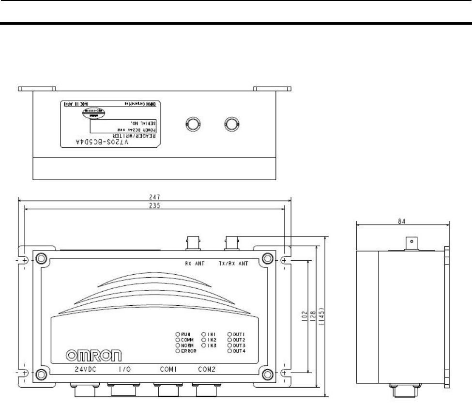
2-1 Reader/Writer (V720S-BC5D4A) 2-1
2-2
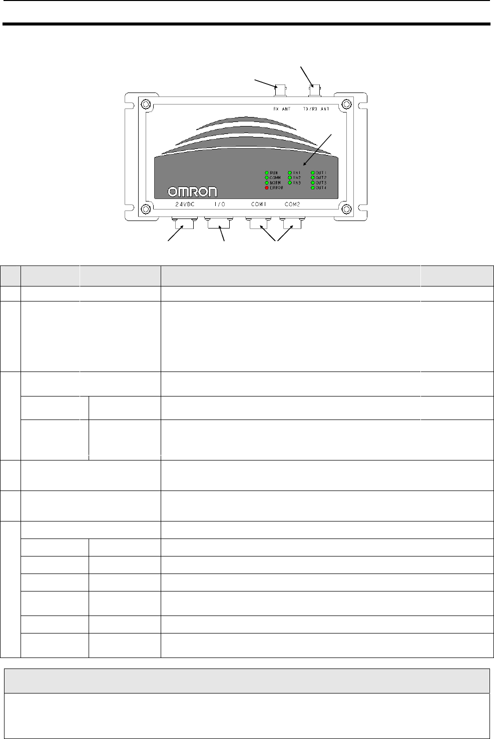
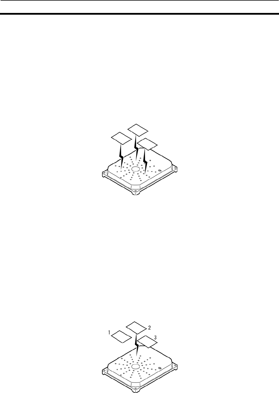
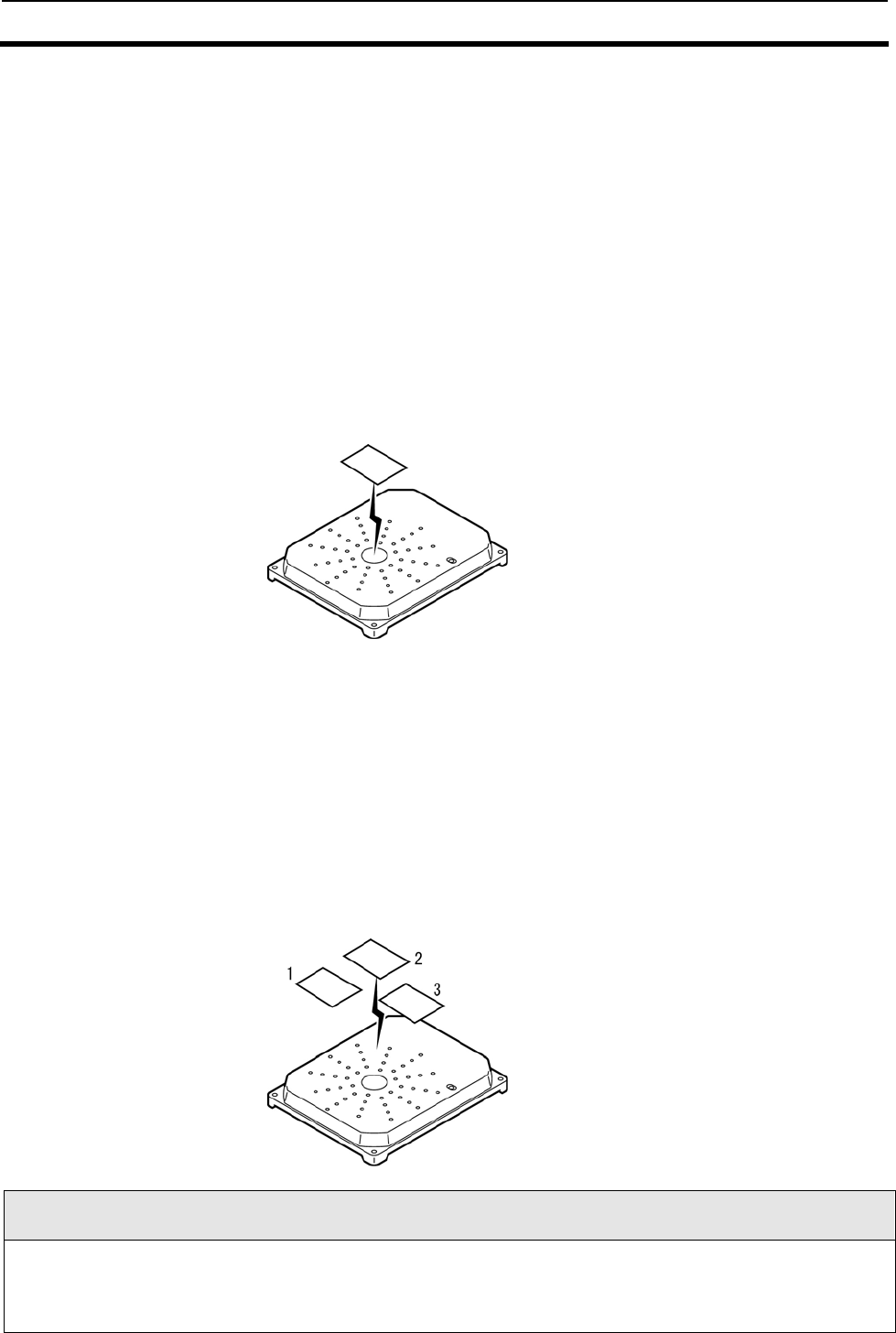
2-1-1 Nomenclature
N
o. Name Function/description
1 Power connector Connects 24 VDC.
2 Input/Output connector
This connector can connect the following signals:
z External RESET signal input (1 point)
z User input readable via command (3 points)
z User output operable via command (4 points)
* For the application of specialized antennas, some outputs are reserved for
exclusive use. For the connection in such cases, refer to the respective
Antenna Manual.
Host communication connector Connects a PLC, PC, or the like to transmit commands to and receives
responses from the Reader/Writer.
COM1 This is a host port used for ordinary communication. The interface conforms to
RS-232C and RS-485, either of which is used selectively as appropriate.
3
COM2
This port conforms to RS-232C and is solely used for setup. The RS-232C
interface of this port operates independent of the RS-232C interface of COM1.
The RS-485 pin is provided for extension when multi-dropped connection is
used.
4
Transmitting/receiving
antenna connector (TX/RX
ANT)
Connects an antenna (the V720-HS04 or the like).
5 Receiving antenna connector
(RX ANT)
A receive-only antennal can be connected to this connector. This connector is
provided for special applications, e.g., connection with a gate antenna. Leave
this connector unconnected in normal use.
Indicators The indicators shows the state of operation, as shown below:
RUN Green Turns on when the Reader/Writer is operating normally.
COMM Green Turns on when the Reader/Writer is in communications with the Tag.
NORM Green Turns on when communication has completed normally.
ERROR Red zTurns on when a communication error has occurred.
zTurns on when a system error has occurred.
IN1 - IN3 Green Turns on when the input signal is on.
6
OUT1 - OUT4 Green Turns on when the output signal is on.
Note
●Do not connect antennas other than those recommended by OMRON.
●When connecting a Receive-only Antenna, enable the Receive-only Antenna Mode with the Antenna Changeover
Command (AC).
(4) Connector for
send/receive antenna
(1) Power supply
connector
(6) LED Display
(3) Connectors for host (s)(2) I/O connector
(5) Connector for
receiving
antenna
(4) Connector for
send/receive antenna
(1) Power supply
connector
(6) LED Display
(3) Connectors for host (s)(2) I/O connector
(5) Connector for
receiving
antenna
2-1 Reader/Writer(V720S-BC5D4A) 2-1
2-3
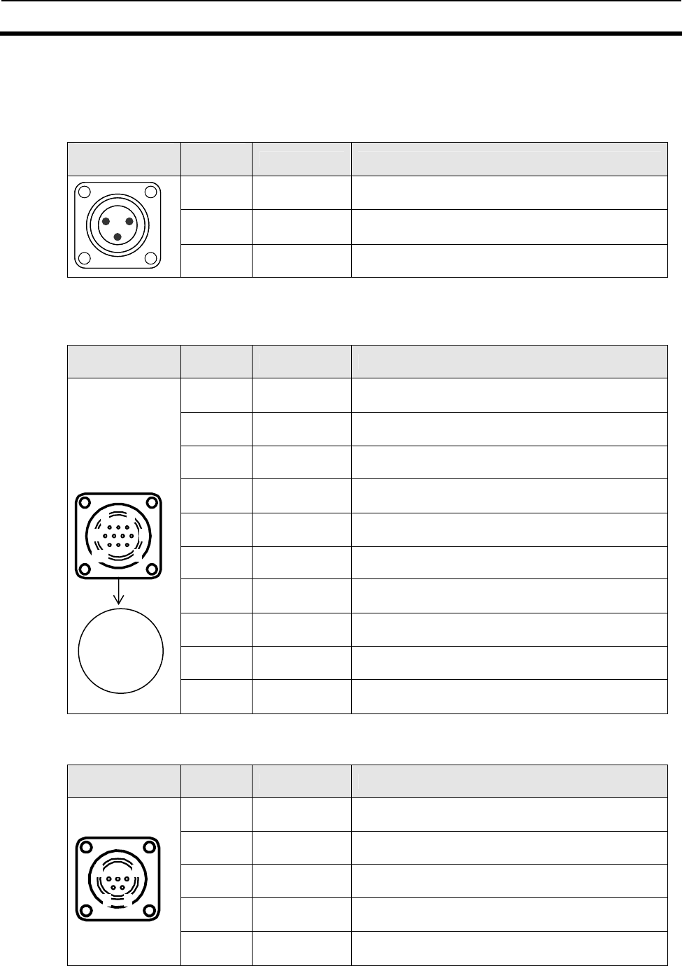
2-1-2 Names of Connector Terminals
Each connector shows pin numbers ,which are viewed from the outside of
the Reader/Writer.
1. Power connector
Shape of
connector
Pin
number Name Description
1 GND Connects 0V.
2 + 24 VDC Connects the + side of 24 VDC.
1 2
3
1 2
3
3 GR Connecting to a ground of 100 Ω or less
2. Input/Output connector
Signals have been insulated from one another. The input and output
signals are connected in a pair to INCOM and OUTCOM, respectively.
Shape of
connector
Pin
number Name Description
1 RST RESET signal input
2 IN1 External input signal 1
3 IN2 External input signal 2
4 IN3 External input signal 3
5 INCOM
Common terminal for common use by external input
signals
6 OUT1 External output signal 1
7 OUT2 External output signal 2
8 OUT3 External output signal 3
9 OUT4 External output signal 4
10 OUTCOM
Common terminal for common use by external
output signals
3. Host communication connector
COM1 and COM2 are set commonly, as shown below.
Shape of
connector
Pin
number Name Description
1 RD Receive data (RS-2332C)
2 SD Transmit data (RS-2332C)
3 SG Grounding for signals (RS-232C)
4 + + (RS-485)
5 - - (RS-485)
1
3 2 1
7 6 5 4
10 9 8
3
4 7
8
10
1 2 3
4 5
2-2 Specifications 2-2
2-4
2-2-1 General Specifications
Item Specifications
Supply voltage 24VDC ±10%
Power consumption 27 W or less
Ambient operating
temperature -10℃ to 50℃ (with no icing)
Ambient operating humidity 35% to 85% RH (with no condensation)
Ambient storage temperature -25℃ to 65℃ (with no icing)
Insulation resistance
20 MΩ min. (by a 100 VDC mega) between both
I/O terminals and both power supply terminals,
between both COM terminals, and between both
ANT terminals
Dielectric strength
Leakage current of 10 mA max. at 1000 VAC
(50/60 Hz) for 1 minute in any of the above
combinations
Vibration resistance
No abnormal condition after applying 10 sweeps
of a vibration of 10 to 150 Hz and 0.2mm double
amplitude in X, Y, and Z directions for eight
minutes
Shock resistance
No abnormal condition after giving an impact of
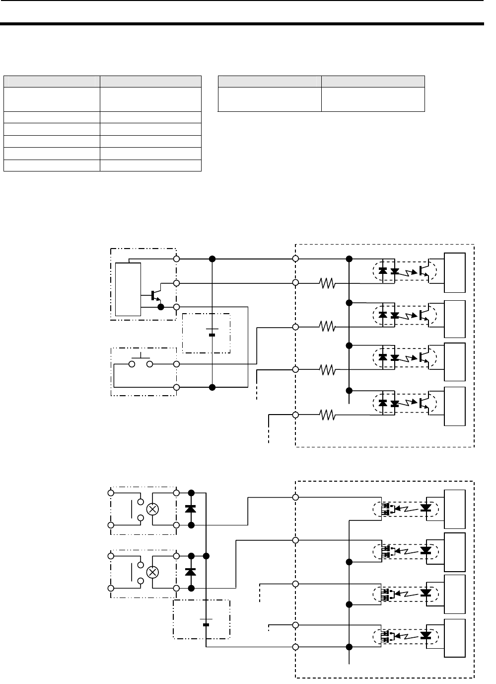
150 m/s2 three times each in X, Y, and Z
directions, i.e., 18 times in total
Grounding Connecting to a ground of 100 Ω or less
Dimensions 247 x 84 x 128 mm (W×H×D)
Protective construction IP60 (IEC60529 Standard)
Number of terminals for
antenna connection
Transmitting/receiving antenna: 1
Receive-only antennal: 1
Material Aluminum die casting
Mounting method Fastening with M6 screws
Standby time*1 15 min
Weight Approx. 1.6 kg
:(*1) The time that elapses after turning power ON to getting stable for
communication.
2-2-2 Performance Specifications
Item Specifications
Self-diagnostics CPU Error, System Error, Host communication
Error, Tag Communication Error.
Initialization process at power-on
During the initialization process after power-on, four LED indicators: RUN, COMM, NORM, and ERROR light up.
No commands are accepted during the initialization process (approximately 2.5 seconds).
2-2 Specifications 2-2
2-5
2-2-3 Reader/Writer Communications Specifications
1. Transmission specifications
Item Specifications
Central carrier frequency 13.56 MHz ± 7 kHz
Antenna output V720S-BC5D4: 4.0 W or less
Output impedance: 50Ω
Modulation method ASK
Degree of modulation 10% to 20%
Coding method Fast mode: RZ/1 out of 4
Standard mode: 1 out of 256
Baud rate Fast mode: 26.5 kbps
Standard mode: 1.65 kbps
2. Receipt specifications
Item Specifications
Central carrier frequency 13.56 MHz ± 7 kHz
Sub-carrier 424 kHz
Modulation method ASK modulation on sub-carrier
Coding method Manchester encoding
Baud rate 26.5 kbps
Note
The Standard Mode and Fast Mode are specified by the Tag Communications Mode Setting Command (CM). It
should be noted that the factory default setting is the Fast Mode.
2-2 Specifications 2-2
2-6
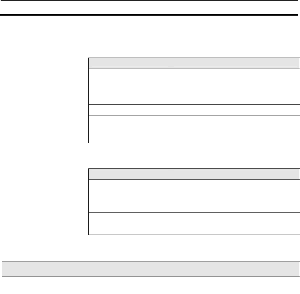
2-2-4 I/O Specifications
Input specifications (RST, IN1, IN2, and IN3) Output specifications (OUT1, OUT2, OUT3, and OUT4))
Item Specifications Item Specifications
Input voltage 24VDC ± 10%
(including ripples)
Max. opening and
closing capacity
24VDC ± 10%, 50mA
(including ripples)
Input impedance 2.2 kΩ
Input current 10mA TYP (24 VDC)
ON voltage 19 V min.
OFF voltage 5 V max.
Input response time 70 ms max.
Wiring with I/O equipment (Ex.)
NPN transistor output
Open collector type
(e.g., 3-wire type sensor)
Internal
circuit
2.2kΩ
Internal
circuit
2.2kΩ
Internal
circuit
2.2kΩ
Internal
circuit
2.2kΩ
Internal
circuit
Internal
circuit
Internal
circuit
Internal
circuit
Internal circuit
sensor
Reader/Writer input part
INCOM
IN1
IN2
IN3
Output
DC24V +
Power supply
RST
Reader/Writer output part
Mechanical switching
type
(e.g., push button SW)
OUT1
OUT2
OUT3
OUT4
OUTCOM
Relay
Relay
DC24V +
Power supply
+V
0V

2-2 Specifications 2-2
2-7
2-2-5 Host Communications Specifications
The RS-232C interfaces for COM1 and COM2 have separate communication ports, and thus it is
possible for these interfaces to have different communication settings. COM1 can be communicated via
RS-232C or RS485 interfaces. RS-232C for COM2 is primarily used for Reader/Writer setup, whereas
RS-485 pin at COM2 is used for multi-drop connection to other Reader/Writer devices.
COM1 connector
Item Description
Conforming standard RS-232C or RS-485
Communications
method
EIA/TIA-232-E half duplex or
EIA/TIA-485 half duplex
Baud rate 9600 bps, 19200 bps, 38400 bps, 115200 bps
Sync Start-stop synchronization (stop bit: 1 or 2)
Transmission code ASCII7 or JIS8 unit symbols
Max. number of
connections 31 (for connection via RS-485 Interfaces)
Error control Vertical parity (select from even, odd, or none)
For BCC, use or non-use of horizontal parity can be selected.
Line length 4) 15 m (when RS-232C is selected)
300 m in total (when RS-485 is selected)
COM2 connector
Item Description
Initial value
(after resetting power
supply)
Conforming
standard RS-232C -
Communications
method EIA/TIA-232-E half duplex -
Baud rate 9600 bps, 19200 bps, 38400 bps, 115200 bps 9600 bps
Sync Start-stop synchronization (stop bit: 1 or 2) Stop bit 2
Transmission
code ASCII7 or JIS8 unit symbols ASCII 7
Error control
Vertical parity (select from even, odd, or none)
For BCC, use or non-use of horizontal parity can be
selected.
• even
• Use for BCC
Line length 4) smaller than or equal to 15 m -
Communication Settings
1) Either RS-232C or RS-485 interfaces must be selected for COM1.
2) The Communication Settings for COM1/COM2 are set using Communications Port Setting Command (CP).
3) The COM2 Communication Settings are reset to the initial values at power reset.
(The settings are maintained when reset with Reset Command) (XZ).
4) The line length may be shorter depending on the transmission rate applied, be sure to confirm the length in
advance.
2-2 Specifications 2-2
2-8
2-2-6 Dimensions
2-3 Cable (sold separately) 2-3
2-9
2-3-1 General Specifications
Model
Item
V720-A 41
Antenna cable
V720-A 51
Power cable
V720-A 62
RS-232C cable
Cable type Coaxial cable - -
Number of conductors 2 (shield) 3 6
Insulation resistance 10 MΩ min. (at 250
VDC) between
conductor and shield
5 MΩ min. (at 250 VDC)
between conductor and
shield
10 MΩ min. (at 250
VDC) between
conductor and shield
Dielectric strength Leakage current of 1mA
max. at 300VAC
Leakage current of 1mA
max. at 300VAC
Leakage current of 1mA
max. at 300VAC
Cladding material PVC PVC PVC
2-3-2 Dimensions
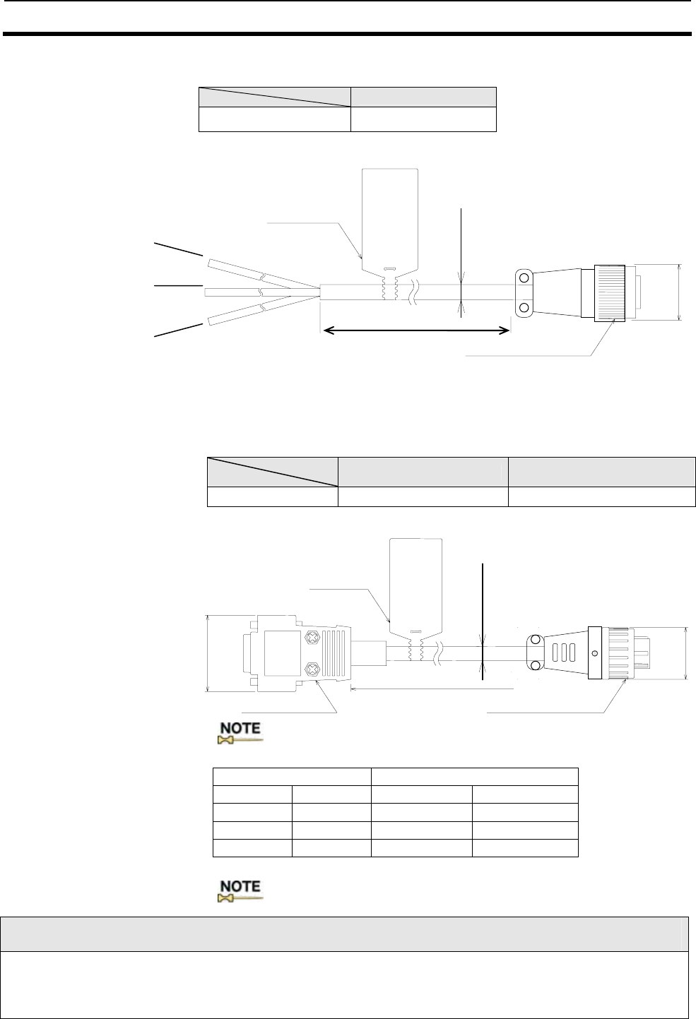
■Antenna cable: V720-A41
Model
Item V720-A41 3.35M V720-A41 10.33M
Length 3350 +20-30 (mm) 10330+20-30 (mm)
Connection label
Connector (Reader/Writer side)
Ф5.5(mm)
Connector (Antenna side)
L1
15
Antenna Cable Wiring
● Be sure to use V720-A41 3.35M or V720-A41 10.33M for the antenna cable. Using other cables may affect
communication performance.
● Do not change the cable length. Doing so may affect communication performance.
2-3 Cable (sold separately) 2-3
2-10
■Power cable: V720-A51
Item Model V720-A51
Length (L1) 3000+10-20(mm)
■Cable for RS-232C: V720-A62(For DOS/V PCs)
Item Model V720-A62 3M V720-A62 15M
Length (L1) 3000+50-0 (mm) 15000+50-0 (mm)
Connect label
Connector (Reader/Writer) Connector (Host side)
L1
Ф6.6(mm)
Ф22
32.2
:The D-sub connector is an inch screw thread (M2.54) type.
D-sub connector Reader/Writer-side connector
2 pin RD 1 pin RD
3 pin SD 2 pin SD
5 pin SG 3 pin SG
Housing Shield
:Connect the shield wire to the connector cover on the PC side.
Installation/Operation Precautions
The cable must be laid in a particular manner so that no mechanical stress is applied to the cable.
The cable should not be repeatedly bent or pulled in an axial direction.
Red(+24VDC)
Black(0V)
White(GR)
Connection label
Connector (Reader/Writer side)
Ф7.8(mm)
Ф22(mm)
L1
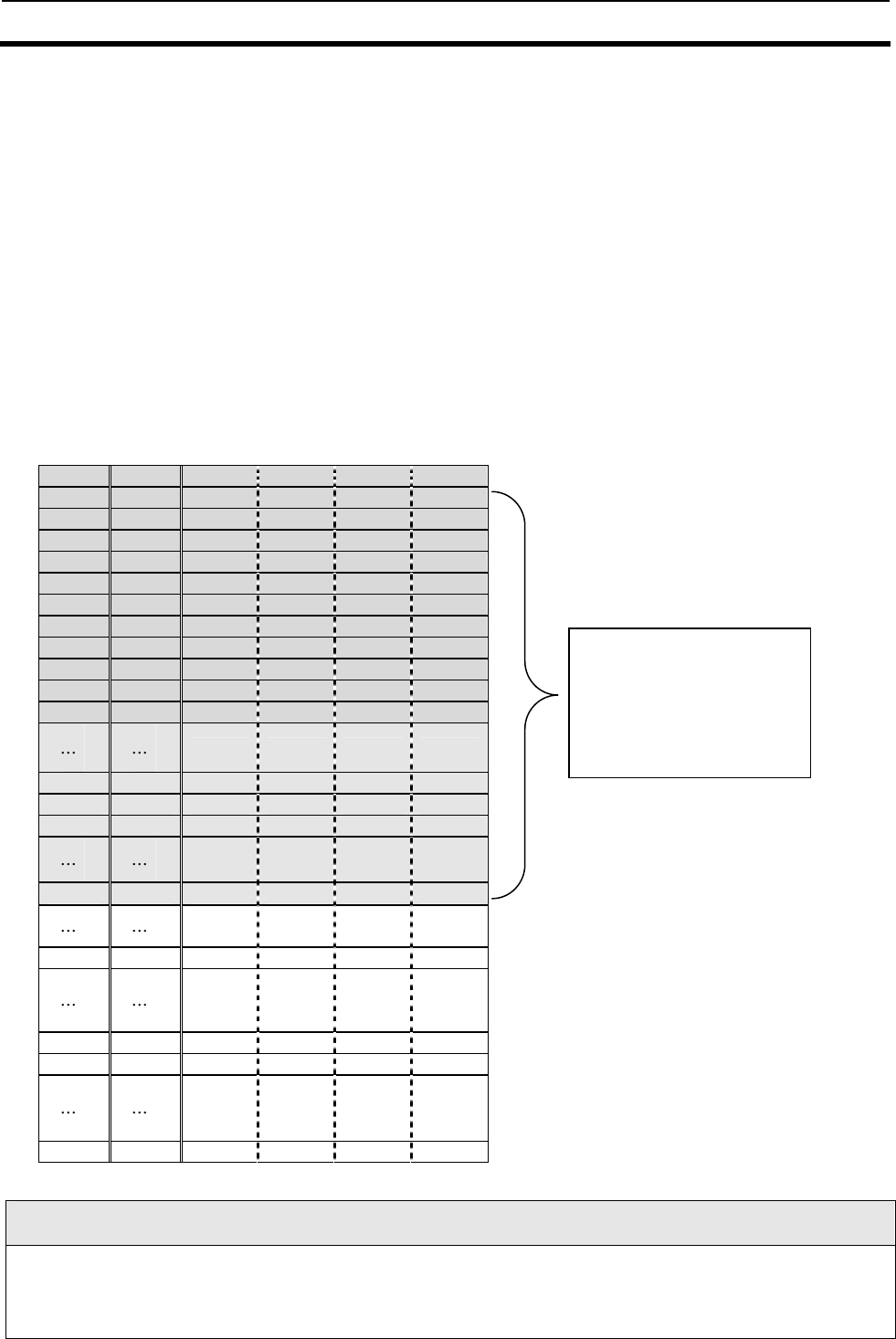
2-4 Memory Map of Tag 2-4
2-11
2-4-1 I.CODE SLI Chip (Philips Semiconductor IC, product name: SL2 ICS20)
This section describes a Tag incorporating a Philips Semiconductor IC
chip SL2 ICS20 Label IC (hereinafter called “I.CODE SLI chip”), which is
accessed by the system.
This chip is in conformity with international standards or ISO/IEC15693.
The user memory area of I.CODE2 chip consists of 28 pages (00h through
1Bh page) or 112 bytes.
This Reader/Writer is organized with one page (4 bytes) as the minimum
access unit of its memory block, and can be accessed up to the maximum
address space defined in ISO/IEC15693. 1) shows an example of a
Memory Map of an IC (hereinafter called “ISO/IEC chip”) in accordance
with ISO/IEC15693.
1) Maximum address space of ISO/IEC15693 chip organized with 4 bytes/page
Page Block Byte0 Byte1 Byte2 Byte3
00h 0
01h 1
02h 2
03h
04h
05h
06h
07h
08h
09h
0Ah
0Fh 15
10h 16
11h 17
1Bh 27
1F 31
F0h 240
F1h 241
FFh 255
Accessible Tags
●This product incorporates the firmware, which can access the 4-byte/page chip that conforms to ISO/IEC 15693.
However, the operation is guaranteed for OMRON Tags that use the Philips Semiconductor IC, SL2ICS20
(commonly called I.CODE SLI) only. The Tags by other manufactures, or those with other ISO/IEC15693 Chips
should be thoroughly tested by each user.
User memory area of
I・CODE2
Page 00h through 1Bh
(28 page = 112 Byte)
2-4 Memory Map of Tag 2-4
2-12
2) System area of I.CODE2 chip
This section describes a system area of I.CODE SLI chip. The system
area of I-CODE SLI chip is allocated in the other area rather than user
memory area.
Execute a specific command to access to the system area.
The processes in the system area are done by specific commands instead
of page number allocations.
Byte0 Byte1 Byte2 Byte3
UID
UID
EAS/AFI/DSFID
Write-protected
(1) UID
UID is a Tag-specific code and has been written into the memory during
the chip production process.
The IC is shipped with this page write-access inhibited; there is no way of
making this page rewritable by the user.
(2) EAS
EAS mode: Inhibition/permission of EAS function
(e=0: EAS mode is disable; e=1: EAS mode is enable)
MSB LSB
Byte1 × × × × × × × e
The pages marked with “X” in the table above are reserved for future use.
(3) AFI
AFI is special area for enabling the user to identify a Tag that is suitable
for a specific user application.
MSB LSB
Byte2 AFI higher-order 4bits AFI lower-order 4bits
■Definitions by ISO/IEC15693
AFI higher-order
4 bits
AFI lower-order
4 bits Applications Example
0 0 All applications None specified applications
X 0 X applications Select extensively
X Y
Y sub classification of
X application
0 Y
Limited applications
to Y sub classification
1 0,Y Transportation
Mass transportation, bus,
airplane
2 0,Y Finance Banks
3 0,Y Recognition Access control
4 0,Y Telecommunication Public telephone, CSM
5 0,Y Medical care
6 0,Y Multimedia Internet
7 0,Y Game
8 0,Y Data storage Portable file
9 0,Y
Physical distribution
management
A 0,Y Package delivery
B 0,Y Postal mail
C 0,Y Air hand baggage
D 0,Y Hold
E 0,Y Hold
F 0,Y Hold
*Note: X=1 through F Y=1 through F
2-4 Memory Map of Tag 2-4
2-13
(4) DSFID
DSFID indicates how data are organized in a memory.
MSB LSB
Byte3 DSFID
(5) Write-access conditions
The pages are write-inhibited permanently if they are so indicated in the
memory map. The factory settings are as follow. If the bit of a particular
page is 1, that page is write-protected.
MSB LSB
Byte0 0 0 0 0 0 0 0 0
Page
03
Page
02
Page
01
Page
00
Byte1 0 0 0 0 0 0 0 0
Page
0B
Page
0A
Page
09
Page
08
Page
07
Page
06
Page
05
Page
04
Byte2 0 0 0 0 0 0 0 0
Page
13
Page
12
Page
11
Page
10
Page
0F
Page
0E
Page
0D
Page
0C
Byte3 0 0 0 0 0 0 0 0
Page
1B
Page
1A
Page
19
Page
18
Page
17
Page
16
Page
15
Page
14
2-4 Memory Map of Tag 2-4
2-14
2-4-2 I.CODE1Chip (Philips Semiconductor IC, product name: SL1 ICS30 01, SL ICS31 01)
These specifications describe a Tag incorporating an IC chip I- CODE1
Label IC (product name: SL1 ICS30 01) from Philips, which is accessed
by the system.
This chip consists of a 64-byte memory. The upper five blocks (Blocks 0
to 4) of the memory are used as a system area having functions that do
not relate to user memory. OMRON offers special commands for
accessing this area in order to ensure the great ease of these functions by
the user.
Refer to 5-5 "System commands" for details. OMRON defines the
blocks below Block 5 as the user memory area. Block 5 is page 00, and the
subsequent blocks are allocated as shown below.
The memory is organized with four bytes as one page (4 bytes = 32
bits).
One page is the minimum unit that can be read from and written to the
memory.
The memory allocation described in these specifications is in
accordance with OMRON's memory allocation scheme.
1)Memory map of I.CODE1Chip
OMRON PHILIPS
(Page) byte 3 byte 2 byte 1 byte 0 (Block)
FB SNR (Tag-specific code) 0
FC SNR (Tag-specific code) 1
FD Write-protect 2
FE QUIET/EAS 3
FF Family code /application ID or user area 4
00 User area 5
01 6
02 7
03 8
04 9
05 10
06 11
07 12
08 13
09 14
0A 15
Page FF (Block 4)
Page FF (Block 4) can be used as user memory when Tag-discriminating access by Family Code (FC) or
Application ID (AI) is not performed. In this case, specify FF for the page to use it as user memory. The user
memory contains 12 pages.
User memory
12 page
(48 Byte)
User memory
11 page
(44 B
y
te)
2-4 Memory Map of Tag 2-4
2-15
2) System area of I.CODE2 chip
1)SNR (pages FB and FC)
SNR is a Tag-specific code and has been written into the memory
during the chip production process.
The IC is shipped with this page write-access inhibited (refer to page
FD); there is no way of making this page rewritable by the user.
2)Write-access conditions (page FD)
The pages are write-inhibited permanently if they are so indicated in
the memory map. The factory settings are as follow. If the two bits of a
particular page are 0,0, that page is write-protected.
Page FD MSB LSB
Byte 0 1 1 1 1 0 0 0 0
Page FE Page FD Page FC Page FB
Byte 1 1 1 1 1 1 1 1 1
Page 02 Page 01 Page 00 Page FF
Byte 2 1 1 1 1 1 1 1 1
Page 06 Page 05 Page 04 Page 03
Byte 3 1 1 1 1 1 1 1 1
Page 0A Page 09 Page 08 Page 07
3)QUIET/EAS (page FE)
QUIET mode :All the functions of a tag are suspended completely. Use
Reset Quiet Bit to resume these functions.
(q=0: QUIET mode is disabled; q=1: QUIET mode is enabled)
EAS mode : Inhibition/permission of EAS function
(e=0: EAS mode is disabled; e=1: EAS mode is enabled)
Page FE MSB LSB
Byte 0 × × × × q q e e
Byte 1 × × × × × × × ×
Byte 2 × × × × × × × ×
Byte 3 × × × × × × × ×
*The pages marked with "×" in the table above are reserved for future
use.
4)Family code/application ID (page FF)
Family code and application ID are special areas for enabling the user to
identify an IC that is suitable to a specific user application.
Block FF MSB LSB
Byte 0 Family code
Byte 1 Application ID
Byte 2 User area
Byte 3 User area
3-1
SECTION 3
Functions
3-1 Operating Mode.................................................................................................. 3-2
3-1-1 Chip Operating Mode..........................................................................................3-2
3-1-2 Online Mode/Offline Mode...............................................................................3-2
3-2 Communication Modes.......................................................................................3-3
3-2-1 Single Access .......................................................................................................3-3
3-2-2 FIFO Access.........................................................................................................3-3
3-2-3 Multiple Access....................................................................................................3-4
3-2-4 Selective Access...................................................................................................3-4
3-2-5 Fast Read Access: I.CODE1 Mode only .............................................................3-5
3-3 Memory Check Function: I.CODE1 Mode Only................................................ 3-6
3-3-1 Usage...................................................................................................................3-6
3-4 Lock Function.....................................................................................................3-7
3-5 Discriminating Access to Tag Function.............................................................3-8
3-6 External I/O Function........................................................................................ 3-9
3-6-1 External Input......................................................................................................3-9
3-6-2 External Output ...................................................................................................3-9
3-7 EAS Function..................................................................................................... 3-10
3-8 Duplicate Communication Protecting Function [Ver1.20 or higher]................ 3-11

3-1 Operating Mode 3-1
3-2
3-1-1 Chip Operating Mode
This Reader/Writer has two Chip-Operating Modes for different types of
Tags (and its IC Chips.) You have to set either of the Chip Operating
Modes in accordance with the Tag you choose. The functions or command
types/formats vary, depending on the Chip Operating Mode. The factory
default is ISO Mode (I.CODE 1 Mode for Ver1.10 and lower).
The mode is set by the Chip Operating Mode Switch Command (TY).
Operating Mode Operation
ISO Moed Processes the Tags with ISO/IEC15693 Standard
Chips (I.CODE SLI). I.CODE1-Mode specific
functions or commands are disabled.
I.CODE1 Mode Processes the Tags with I.CODE1 Chips.
ISO-Mode specific functions or commands are
disabled.
3-1-2 Online Mode /Offline Mode
The Reader/Writer operates in either Online Mode, in which commands
are given by the host, or in Offline Mode, in which the EAS function (refer
to SECTION 3-7) performs the configuration, when the host is
disconnected and the communication test between the antenna, the
Reader/Writer and the Tags.
The factory default is set to Offline mode. To change the mode to the
Online Mode, connect the host and execute the Stop Command (ST). To
always start the Reader/Writer in the Online Mode, the default mode is
disabled using the Offline Mode Setting Command (FL).
When the Reader/Writer is turned on in Online Mode, it remains in a
stand-by state, until commands from the host are received.
In the Offline Mode, the Reader/Writer starts detecting the EAS-enabled
Tags (the EAS function mounted on the Tags is not disabled) from the
moment it is turned on in this mode the COMM LED remains flashing. At
the entrance of an EAS-enabled Tag into the antenna communication
area, the external output turns ON for the specified time. The OUT1 LED
light indicates normal communication between the Reader/Writer and
the Tags .
To check the communication status in the Offline Mode, the EAS on the
Tags must be enabled in advance.
Note:
●If the type of Tags used and the chip operating mode setting do not match, the Reader/Writer will not
respond to the Tags. The No Tag Error (code: 72) results.
●Specifying the commands or functions unavailable in the specified Chip Operation Mode will result in
a Format Error (code: 14).
●The communication test in Offline Mode is performed with the EAS on the Tags enabled. The
communication by the EAS function takes longer compared to Read/Write operations performed by
other functions. The communication distance in the Online Mode should be checked using the actual
commands.
3-2 Communication Modes 3-2
3-3
This Reader/Writer has five communication modes to be selected by each
command corresponding to the number and/or state of Tags in the
communication area.
Each mode is activated by specifying the communication in the command
data.
3-2-1 Single Access Single Access is used to read data from or write data on the only Tag that
exists in the Antenna Communication Area. The execution timing can be
selected from Trigger, which executes immediately, Auto, which waits for
the Tag to enter the communication area and executes, or Repeat, which
repeats the execution for the Tag in the communication area.
Be sure to have only one Tag in the communication area. Multiple Tags in
the Antenna Communication Area prevents the antenna from
communicating normally.
:In the I.CODE1 Mode, the Tag is processed only once at the entry
into the communication area. It can be reprocessed once it is
outside the area again.
3-2-2 FIFO Access FIFO Access is used to read data from or write data on the Tags
sequentially in the same order they entered the antenna communication
area. (FIFO First In First Out).
The execution timing can be selected from Trigger, which executes
immediately, Auto, which waits for the Tags to enter the communication
area and executes, or Repeat, which continues to wait for the Tags to
enter the communication area.
Since every Tag finished with communications is set to access prohibit,
communications will be possible if only one Tag newly arrives in the
communication area of the Antenna where more than one Tag exists.
An error results, however, if two or more Tags arrive in the
communications area simultaneously. Once an access-prohibited Tag
leaves the communications area, access to the Tag is enabled again.
3-2 Communication Modes 3-2
3-4
3-2-3 Multiple Access Multiple Access is used to read data from or write data on the Multiple
Tags in the Antenna Communication area simultaneously.
Communications with Multiple Tags in the communications area is
available. (This function is also called 1:N Access or Multiple Tag
Simultaneous Access). The execution timing can be selected from Trigger,
which executes immediately, or Repeat, which continues to wait for the
Tags to enter the communication area.
In I.CODE1 Mode, specify the appropriate tag-number code in command
data according to the number of Tags that exist in the communication
area (refer to SECTION 5-2-5).
The Duplicate Communication Protecting Function is useful for unstable
Tags in the Antenna Communication Area (refer to SECTION 3-8 for
details).
3-2-4 Selective Access
Selective Access is used to read or write data on specified Tags among the
multiple Tags in the communication area.
In ISO Mode, communication with specific Tags is achieved by first
reading the Tag UIDs (unique codes) in Multiple Access Mode and then by
specifying them. It is recommended that the UID/SNR addition option of
the Command Processing Procedure Setting should be used. It is
especially convenient since data readouts and UID acquisitions are
performed by a single command.
In I.CODE1 Mode, the Tag Detection Command that assigns numbers to
the Tags in the communication area in Multi Access Mode is performed
first, and then the Tag Designation Command that specifies the assigned
numbers is performed to launch the communication with the specific
Tags.
3-2 Communication Modes 3-2
3-5
3-2-5 Fast Read Access: I.CODE1 Mode Only
The Fast Read Access speeds up the data readout in I.CODE1 Mode. The
execution timing can be selected from Trigger, which executes
immediately, Auto, which waits for the Tag to enter the communication
area and executes, or Repeat, which repeats the execution for the Tag in
the communication area.
The function operates the same way as in Single Access mode when the
Tag number code is set to 0; in other cases it is the same as in Multiple
Access Mode.
[When the Tag number code is set to 0 (Single Access Mode)]
By selecting the Trigger or Auto execution timing, the function executes
the same operation as that in normal single access mode but in a shorter
period of time.
When the Repeat execution timing is selected, the function continuously
returns data while the Tags are present in the communication area, this
is useful in confirming the communication area.
[When the Tag number code is set to those other than 0 (Multiple Access
Mode)]
The only execution timing available is Repeat, since the function employs
a simple version of the communication sequence, some Tag data may be
unreadable under the condition where the responses from the Tags collide
frequently. In addition, the function processes and responds to the same
Tags repeatedly while they are present in the communication area.
This function should be used when there is a low number of Tags in the
communication area. When there are a greater number of Tags, the
Multiple Access Mode should be used. The Duplicate Communication
Protecting Function is useful to avoid multiple responses returned to the
same Tag. (Refer to SECTION 3-8).
Note:
●For the I.CODE1 Communication Modes used under the conditions, where Multiple Tags exit in the Antenna
Communication Area (Multiple Access, Selective Access, or Fast Read Modes), the Tag Number Code must be
specified. The maximum number of Tags allowed in the communications area is set previously. (Refer to
SECTION 5-2-5 for details).
3-3 Memory Check Function I.CODE1 Mode Only 3-3
3-6
By adding a check code to the data in the Tag, you can detect data errors
due to the Tag memory (EEPROM) being overwritten, service life, and
unforeseen factors.
The check code uses the CRC code of the generating polynomial X16 + X12
+ X5 + 1.
A memory check is performed using the Memory Check Command (MC),
which writes the check code, and the Memory Calculation Command
(MK), which verifies the check code. In the check block defined using the
header page and the number of pages, the target calculation area is the
area except for the last page of the block, and the last page is the check
code area. The check code uses two bytes in the check code area.
When a check code write command is sent, the CRC code for the data in
the target calculation area is calculated, and written to the check code
area. When the data verification command is sent, the CRC code for the
data in the target calculation area is calculated, and compared with the
data in the check code area. If these match, the number 75 is returned in
the response code to show that the data is normal. If they do not match,
the number 76 is returned to show that there is a data error.
Example: Memory check is performed when check block header page is 00
and the number of check blocks is 0B.
00
01
・
・
・
09
0A
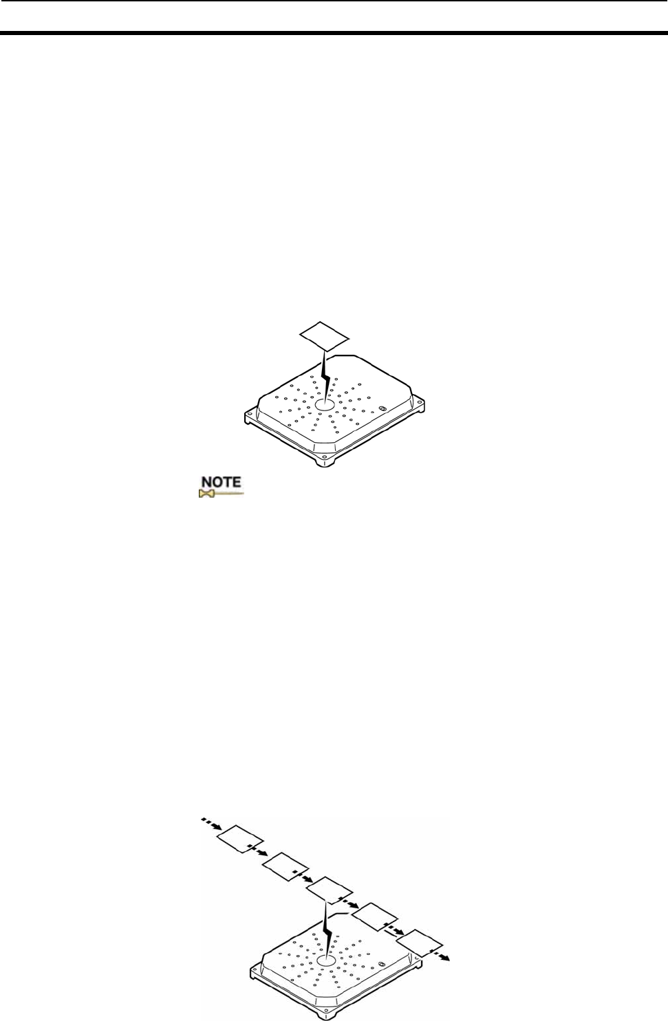
3-3-1 Usage After writing the data, calculate and write the check code using the
Memory Check Command (MC), and before reading the data, verify the
check code using the Memory Calculation Command (MK). You can detect
data corruption in advance within the Tags that are not being accessed.
Write data
Write stage
Calculate check code
Verify check code
Read stage
Read data
: This Command is for I.CODE1 Mode Only. The command is not available in ISO mode:
Check code area
Check code
Calculation area

3-4 Lock Function 3-4
3-7
The Lock function protects data from being erased due to unintentional
overwriting on the fixed data in the Tags.
■ Lock setting in ISO mode For the lock setting in ISO mode, you can write-protect any given areas by
the page of Tag memory.
If you execute Write command on a write-protect page, a write processing
error (code:79) will occur. You can make the lock setting by executing the
Lock command (LK) that enables access to the lock setting area.
For the details, see 5-4-7 “Lock Setting: ISO Mode.”
■ Lock setting in I.CODE1 mode
There is a lock setting area in the system area of I.CODE1 chip, and you
can write-protect any given areas by page.
If you execute Write command on the write-protect page, the write
processing error (code:71) will occur.
The lock setting consists of 12 bits of data in total, giving one bit to each
page. Lock setting can be made by using the Lock command (LK).
For the details, see 5-5-9 “Lock Setting: I.CODE1 Mode.”
●Lock setting area of I.CODE1 chip: “FDh page”
Lock Setting Area
1 byte 1 byte
b7 b6 b5 b4 b3 b2 b1 b0 b7 b6 b5 b4 b3 b2 b1 b0
Page 10
Page 09
Page 08
Page 07
Page 06
Page 05
Page 04
Page 03
Page 02
Page 01
Page 00
Family
code,
application
ID
QU IET
EAS
Write
Protect
SNR
SNR
Note:
●The write protection cannot be canceled by the V720-series lock function. Data can never be re-written into
write-protected pages; be careful in setting write protection.
●Be extremely careful when setting write protection in the system area.
●Tag-specific codes (UID on I.CODE SLI/SNR on I.CODE1) are write-protected when manufactured.
3-5 Discriminating Access to Tag Function 3-5
3-8
The ID codes set in the Tags are utilized in identifying the target chips in
the antenna’s application fields. Responses are returned only when the ID
code in the command from the antenna and the ID code on the Tag are
matched.
The factory default of the Reader/Writer ID codes are all set to 00h, which
means communications are available regardless of ID codes on the Tags.
■I.CODE1 mode
The I.CODE1 chip has two kinds of one-byte ID codes called the Family
Code and Application ID. The Tag ID code can be set/modified by the
Write Command (WT) with the Family Code/Application ID area (FF
page) specified.
The ID codes for the Reader/Writer can be set/modified by the
Reader/Writer Family Code Setting (FC)/Reader/Writer Application ID
Setting (AI) Command.
In I.CODE1 mode
Reader/Writer set value Tag set value
No. Family code Application ID
No Family code Application ID
(1) 00h 00h A 55h AAh
(2) 55h 00h B 55h 11h
(3) 55h AAh C 00h 00h
Reader/writer setting (1)
This setting enables communication with Tag A, B, and C, as both of
the family code and application ID are set to “00h.”
Reader/writer setting (2)
This setting enables communications with Tag A and B as their
family codes match. Communication with Tag C is not possible. This
identification code has nothing to do with identifying Tags as the
application ID is “00h.”
Reader/writer setting (3)
The communication with Tag “A” is possible as the family code and
application ID match. The communication with Tag B and C are not
possible.
■ISO Mode
Both the I.CODE SLI and ISO/IEC Chips have a one-byte ID code called
AFI (Address Family Identifier). To use this function, the AFI’s must be
set for the Reader/Writer and Tags, and the function must be enabled on
the Reader/Writer as well. The Tag ID codes are set/modified using the
System Write (SW) Command. The ID codes for the Reader/Writer are set
by the Reader/Writer AFI Enable/Disable Changeover (AE) Command or
the Reader/Writer AFI Value Setting (AF) Command.
In ISO mode
No. Reader/Writer AFI set value
No. Tag AFI set value
(1) 00h A 5Ah
(2) 0Ah B 0Ah
(3) 5Ah C 00h
Reader/writer setting (1)
This setting enables communication with Tag A, B, and C as AFI is
set to “00h.”
Reader/writer setting (2)
This setting enables communication with Tag A and B of which the
AFI’s 4 least significant bits “Ah” match. As the 4 most significant
bits are “0h,” the part of this identification code has nothing to do
with identifying a Tag.
Reader/writer setting (3)
The communication with Tag “A” is possible as AFI matches.

3-6 External I/O Function 3-6
3-9
The I/O connector has three external input ports and four external output
ports to which such devices as sensors or actuators are connected to build
a more efficient system.
The external output may be dedicated to the antenna control, depending
on the Reader/Writer settings.
3-6-1 External Input [Online Mode]
The status can be obtained by the I/O Control Command (CC). Sequenced
operations such as those for starting and terminating the communication
with Tags by external triggers are available.
[Offline Mode]
Not available. The I/O Control Command (CC) is rejected. To perform the
function, the mode must be switched to the Online Mode by the Stop
Command (ST).
3-6-2 External Output
[Online Mode]
The output status can be modified or read-out by the I/O Control
Command (CC.) Read-out data can be evaluated by the host and output
as a control signal for Lamps or sounds.
When the I/O Automatic Changeover Setting is enabled, the external
outputs 3 (OUT3) and 4 (OUT4) are dedicated to the antenna control and
thus unmodifiable. However, the output status can be read-out.
[Offline Mode]
The external output is dedicated to the control from the Reader/Writer in
this mode. Modification/Reading out of the output status by the I/O
Control Command (CC) is unavailable.
The external output 1 (OUT1) is turned ON for a specified period of time
(modifiable) when Tags with the uncanceled EAS is detected. The
external outputs 3 (OUT3) and 4 (OUT4) are dedicated to antenna control
when the I/O Automatic Changeover setting is enabled.

3-7 EAS Function 3-7
3-10
The Reader/Writer supports the EAS (Electronic Article Surveillance)
system applied for anti-theft and other devices. The Reader/Writer
identifies the unique data string returned by the EAS-bit enabled Tags
and detects the existence of the Tags in the communication area. Multiple
EAS-bit enabled Tags that exist simultaneously can also be detected. The
Reader/Writer stops detecting the Tags by disabling the EAS bit on the
Tags. This is useful in preventing unauthorized removal of properties or
giving caution.
The function operates in either Online Mode, where the function is
executed by the commands issued by the connected host, or Offline Mode
where the function is executed by the Reader/Writer alone.
[Offline Mode]
In the Offline Mode, the EAS-bit enabled (non-disabled) Tags are
continuously detected. When the EAS-bit enabled Tags enter the
Antenna Communication Area and their EAS-response concordance rate
exceeds the specified value (=EAS threshold), the external output 1
(OUT1) will turn ON for the specified time. The operation state is visibly
identified by the OUT1 LED light. The EAS threshold and external
output time are specified by the Offline Mode Setting (FL) Command.
●EAS threshold
The Tags return 256-bit fixed data. The concordance rate at which the
Tag is recognized as one with non-disabled EAS (EAS-bit disable
processing is not performed) is specified by a percentage. The smaller the
concordance rate, the more lax the criteria becomes. The initial threshold
is 75%.
●The ON-time of the external output 1 (OUT1)
The ON-time is specified according to the output time of the lamp or
buzzer. The initial output time is 500ms.
[Online Mode]
The EAS Check (EA) Command is executed from the host. (Refer to
SECTION 5-5-10). The EAS-response concordance rate is returned, which
is compared to the threshold in the host and evaluated for the existence of
the EAS-enabled Tags.
■EAS Setting for the Tag
The EAS on the Tag is enabled by a specific command that enables
EAS-bit. For the ISO/IEC chip (I.CODE SLI chip), it is done by the
System Write (SW) Command and for I.CODE1 chip, it is done by the
EAS Setting (ES) Command.

3-8 Duplicate Communication Protecting Function 3-8
3-11
The Duplicate Communication Protecting Function prevents the command that
processes multiple Tags serially from performing multiple Read/Write processing
for each Tag. This function controls the command so that it performs the
processing only once per Tag and returns a single response, even in situations
where a Tag is recognized more than once as shown below. The processing load is
reduced because the response receiving or duplication check by the host is
unnecessary. The communication performance speed is also improved since
unnecessary processing is eliminated in the following:
1. The situation where the Tag enters the Antenna Communication Area several
times due to its vibration, irregular operation, or stop on the boundary, or because
the Tag is in the antenna’s side lobe area.
2. The situation where the Tag is stopped in the boundary zone or enters the
Antenna Communication Area several times because of the moved antenna.
3. The situation where the Tag passes an antenna with a discontinuous
communication area such as the gate antenna.
The enabled function is activated when the commands using the following
communication modes are executed:
・FIFO Repeat Mode (FR)
・Multiple Trigger Mode (MT)
・Multiple Repeat Mode (MR, UR[I.CODE1 Only]*)
When the function is enabled, the unique number (UID/SNR) given to the
processed Tag is recorded in the table of the processed Tags after the command has
been executed. When a new Tag is detected and its UID/SNR is obtained, the
system refers to the table and processes the Tag only when the UID/SNR is not
found in the table. After the Tag has been processed normally, the system records
the UID/SNR in the table. The table is initialized at the start of command.
* As to UR, the page on which the processing is started must be FB, and the pages
must be 2 and more.
The function is set by the Duplicate Communication Protecting Function Setting
(MX) Command (disabled by factory default.) To enable the function, specify the
maximum number of UID/SNRs recorded in the table of the processed Tags. The
number of tables can be selected from 1, 4, 8, 16, 64, 128, or 256. Usually, the
closest number above the maximum number of Tags that can co-exist in the
communication area of the antenna being used is specified.
Example) When the maximum number of the co-existing Tags are 6: The number
of tables = 8
0
1: Tag0
2: Tag1
3: Tag2
4: Tag3
5: (Vacant)
6: (Vacant)
7: (Vacant)
8: (Vacant)
4
The table of the processed Tags:
In this case, Tag 0 is not processed for re-entry in the communication area. When
the Tag 4 enters the area it is processed and recorded in row 5: of the table.
4-1
SECTION 4
From Start-up to Operation
4-1 Operation of Reader/Writer .................................................................................4-2
4-1-1 Offline Mode.....................................................................................................4-2
4-1-2 Online Mode.....................................................................................................4-3
4-2 Trial Operation..................................................................................................... 4-4
4-3 Reader/Writer Setting.......................................................................................... 4-5
4-3-1 Host Communications Setting (COM Port Setting) ......................................4-5
4-3-2 Chip Operating Mode Setting.........................................................................4-6
4-3-3 Command Processing Procedure Setting.......................................................4-7
4-3-4 Antenna and Tag Communications Setting...................................................4-8
4-3-5 Offline Mode Setting........................................................................................4-9
4-3-6 Initialization of settings..................................................................................4-9
4-3-7 Fixing of Settings.............................................................................................4-9
4-4 Installation Environment ....................................................................................4-10
4-4-1 Installation.......................................................................................................4-10
4-5 Mounting Method................................................................................................. 4-11
4-5-1 Mounting Dimensional Drawing ....................................................................4-11
4-6 Wiring Method......................................................................................................4-12
4-6-1 Power Supply and Grounding Wires ..............................................................4-12
4-6-2 Host Communications Cabling.......................................................................4-13
4-6-2-1 RS-232C Interface Cabling..........................................................................4-13
4-6-2-2 RS-485 Interface Cabling............................................................................4-15
4-6-3 Assembly of Connector ....................................................................................4-18
4-6-3-1 Assembly of Host Communications Connector and I/O Connector ..........4-18
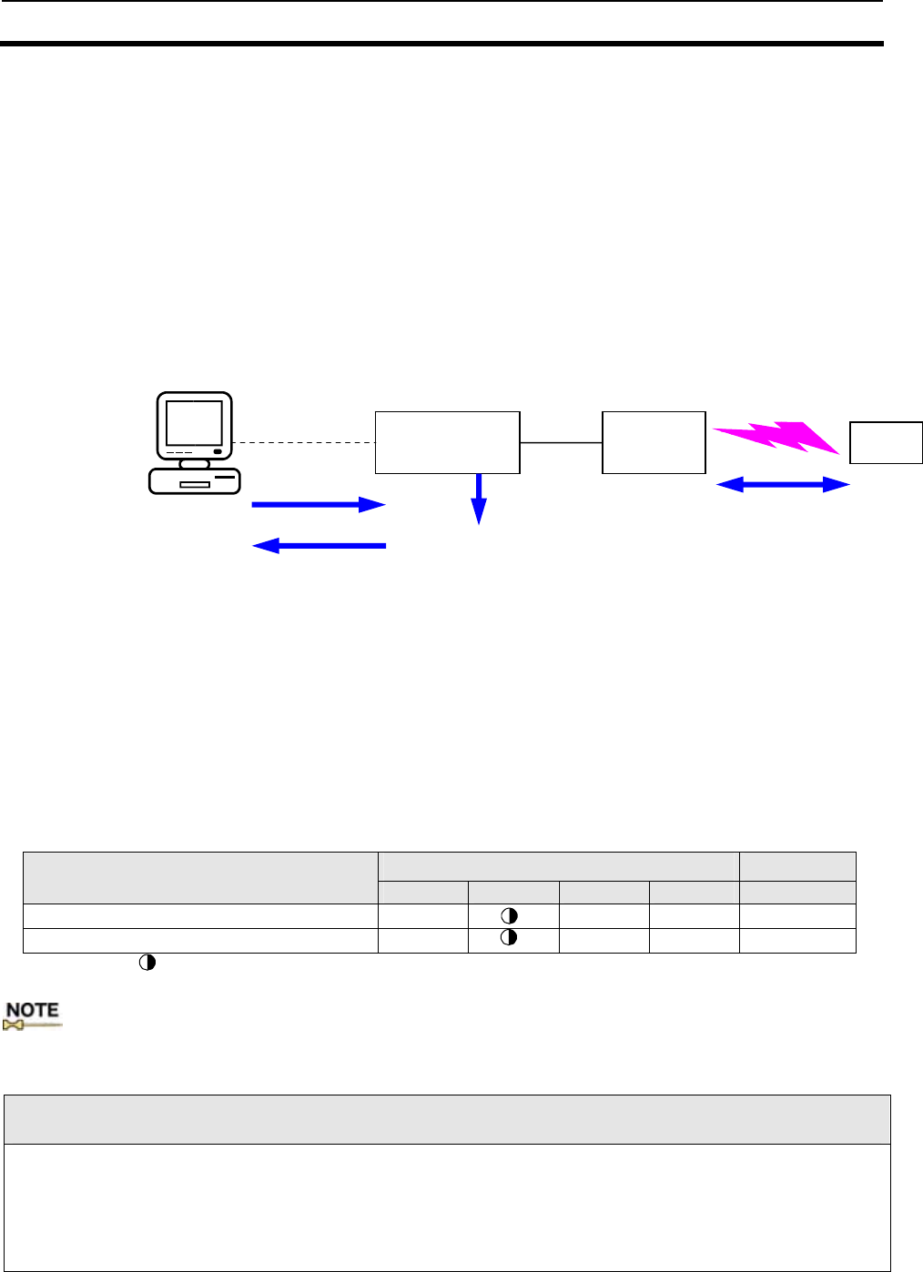
4-1 Operation of Reader/Writer 4-1
4-2
The V720-series RFID system has two operation modes: Offline Mode and Online Mode. The functions
and control methods by the host vary, depending on the Operation Mode. One of the two modes must be
selected at system setup.
4-1-1 Offline Mode
In the Offline Mode, the EAS-enabled Tags (the EAS function mounted on the Tags is not
disabled) are always detected (1). When the EAS-enabled Tags enter the antenna
communication area, the output results (OUT1) turns ON for the specified time (2). The control
from the host is unnecessary. The PCs used for setup are connected as needed when the
operating conditions must be specified. Some outputs are exclusively used for antenna control,
depending on the settings.
●Detecting Tags
In the state where the EAS-enabled Tags (the EAS function mounted on the Tags is not disabled), are
being detected, the COMM LED flashes in this state.
●Detection of the EAS-enabled Tags
In the state where the EAS-enabled Tags are present in the Antenna Communication Area. OUT1
turns ON for the specified time. OUT1 stays ON while the Tags are present in the area.
■LED/Output state in each operating status LED state Output
Item RUN COMM NORM ERROR OUT1
Detecting Tags (EAS) ○ ● ● OFF
Detection of the EAS-enabled Tags ○ ○ ● ON
○:ON, ●:OFF, :Flashing
If an error occurs to the value specified in the EEPROM at power-ON, the status enters the specified-value
error state. When this occurs, the factory default value is employed.
Note:
●The factory default is Offline Mode.
●To specify Offline Mode operations (Chip Operation Mode, EAS threshold, OUT1 output time, receiving antenna
settings, antenna control settings, I/O automatic changeover, etc.), the mode must be switched to Online Mode.
●To switch the Offline Mode to Online Mode, connect the host and execute the Stop Command (ST).
●To switch the operation mode at power-ON, disable the mode by the Offline Mode Setting Command (FL).
Reader/Writer Antenna Tag
During
setup with
PC
Setup command (1)
Communication
Radio communication
between antenna and tag
(2) Results output
Antenna control output
Response
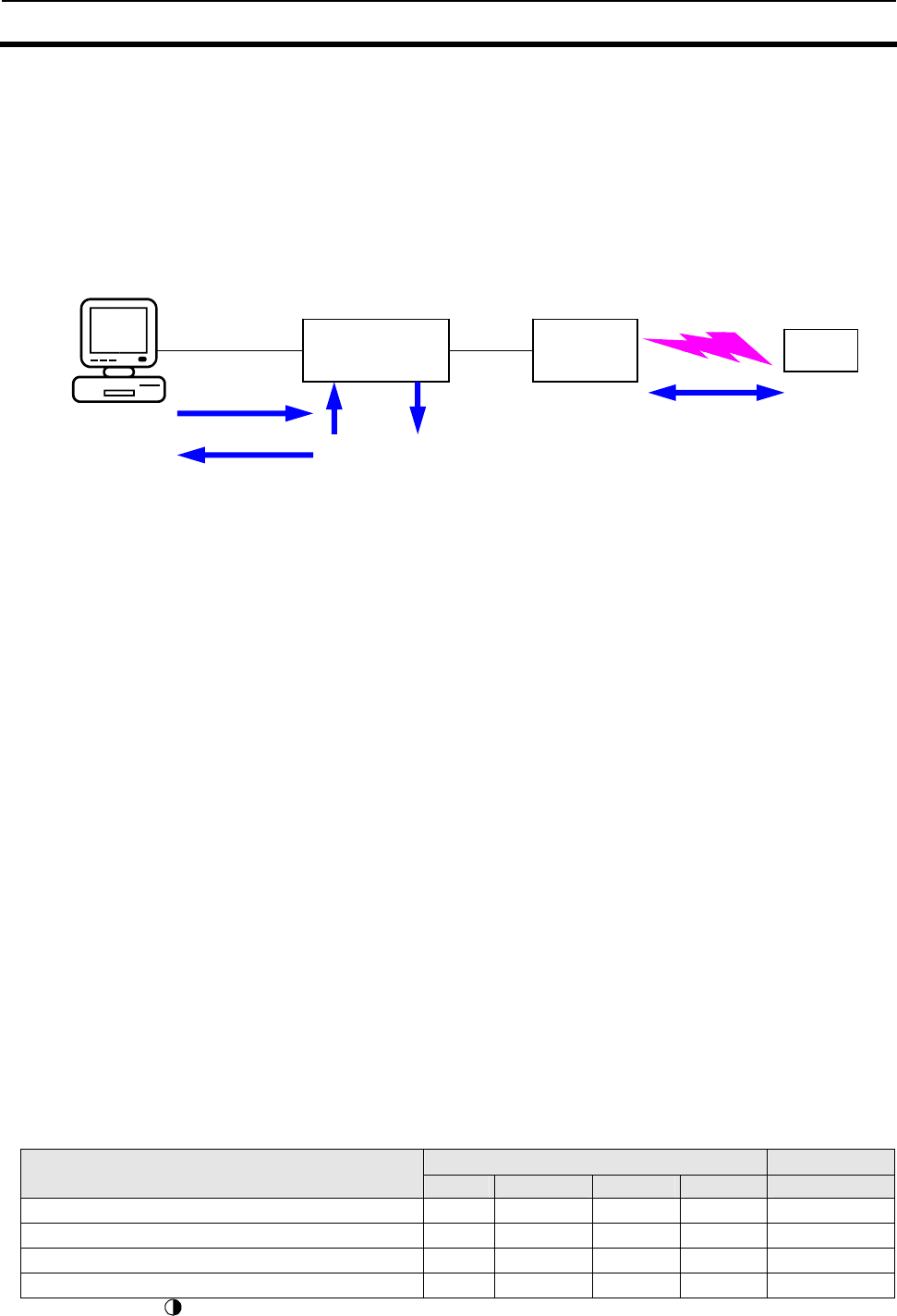
4-1 Operation of Reader/Writer 4-1
4-3
4-1-2 Online Mode
Communication with Tags (2) is performed according to the command (1) from the connected
host. The result is returned to the host as a response (3). The I/O can be read or controlled
using commands. The input can be used as a command execution trigger, and the output can be
used as a result-based control signal for peripherals. Some outputs are exclusively used for
antenna control, depending on the settings.
●Command Standby State
The Command Standby State is where the Reader/Writer is not processing but can accept any
command other than AK or NK, which are used for ACK/NACK control. When the Reader/Writer
accepts a command, it enters the command processing state.
●Command Processing State
When a command is accepted, other commands are ignored until the accepted command has been
processed. However, the Stop (ST) and Reset (XZ) Commands are always accepted. When a command
that performs continuous processing is executed, the processing state continues until completed or
stopped.
The COMM LED is lit (flashed) while communication with the Tags is in progress.
The Reader/Writer enters a special command processing state in the following situations, although it is
not actually communicating with the Tags. The COMM LED is not lit in these cases.
・After the commands have been executed in FIFO trigger or FIFO auto mode
FIFO continuation state where the antenna oscillates continuously: Only the FIFO access
commands are accepted.
・After the Tag Detection Command has been executed (I.CODE1 Mode only).)
Selective state where the simplified numbers of Tags are stored, only the Tag specification
commands are accepted.
●Normal/abnormal completion of command processes
The NORM LED is turned on when the command from the host has been completed normally, and
ERROR LED is turned on if the command has been completed abnormally, for a short period of time at
the returning of the response.
■LED/Output state in each operating status LED state Output
Operation state RUN COMM NORM ERROR OUT1
Command standby ○ ● ● ● (command)*1
Processing with Tags ○ ○ ● ● −
Normal completion of command processing ○ ●/○*2 ○ ● −
Abnormal completion of command processing ○ ●/○*2 ● ○ −
○: ON, ●:OFF, : Flashing , −: Unchanged
*1 Specified by I/O Control Command (CC.)
*2 Stays lit (flashed) when the communication with Tags is continued.
Reader/writer Antenna Tag
(1) Command
(2)
Communication
Radio communication
between antenna and tag.
Multipurpose
input
(3) Response
Host device (PC)
Multipurpose output
(antenna control output)
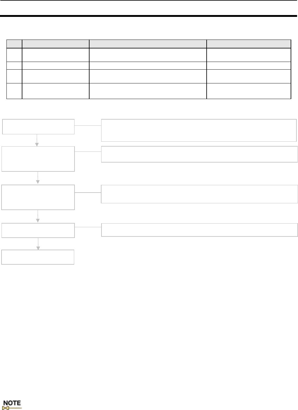
4-2 Trial Operation 4-2
4-4
■Checkpoints Check the following points before starting Trial Operation
No. Checkpoint Description Section-Item
1 Are the power supply
and I/O lines connected Wired properly?
Are the terminal screws properly tightened? SECTION 4-6
2 Antenna connection Is the Antenna connected properly? -
3 Connection to the host Are the RS-232C and RS485 connectors
connected properly? SECTION 4-6
4 Antenna and Tag layout Are the Antenna and Tag located properly? Refer to the Instruction Manual
for your antenna.
■ Procedure for Trial Operation
●Offline test Offline Mode is set by the Offline Mode Setting Command (FL). The default mode is
set for Offline Mode.
By setting the Test Mode, the communications between the Antenna and Tag can be
tested without connecting the host. You can exit the Offline Mode by connecting to
the host and sending a Stop Command (ST)
●Communication
test between the
Reader/Writer and
the host
By using Test Commands(TS), the communications between the Reader/Writer and
host can be tested. This test allows the checking of the cable connection and the
processing operation of communications before the trial operation of the whole
system. It is recommended that RS-232C be connected to COM2 where the
communication condition is fixed.
・Prepare a simple communications program on the host and transmit Test
Commands.
・If the communications line is normal, the Reader/Writer returns the data received.
●Trial
Operation of the
System
Check the operation on the real system using the setting commands under the
actual operating conditions defined by the system design. When using COM1, the
RS-232C cable connection must be modified.
:Conduct the test of the final installation positions of both the antenna and Tag after the lapse of standby
time (15 minutes). Standby time means the time that elapses after turning the power on to getting the
product ready for stable communications
Power ON
・Check the voltage and power source terminal connections.
・Check that the Reader/Writer RUN LED is lit.
Offline Test Check the communication between the antenna and Tags with the Host
disconnected.
Online Test using the
Host
Check the communication between the host and Reader/Writer using the test
command.
Trial Operation of the
System Check the total system operation using the commands.
Complete

4-3 Reader/Writer Setting 4-3
4-5
The Reader/Writer has been designed for the user to make all the settings
by issuing commands from the host. The user can use either the COM1 or
COM2 port to make settings. However, we recommend use of the COM2
port because its communications settings have been fixed at factory to
survive a power reset.
In order to fix the information set for the Reader/Writer to survive a
power reset, it is necessary for the user to execute the setting write
command (EW) (refer to 10) in 5-7-14 of Section 5). (This does not apply
to the communications settings for the COM2 port).
4-3-1 Host Communications Setting (COM Port Setting)
Make settings for host communications by using the communications port
setting command (CP)
Setting name
(command name) Port Default set
value Setting
range Description
COM1 38400 bps
Baud rate setting *1
(CP command) COM2 9600 bps
9600 bps
19200 bps
38400 bps
115200 bps
This command sets the baud rate for use in
communications with the host.
COM1 7bits
Data length setting *1
(CP command) COM2 7 bits
7 bits
8 bits This command sets the data length for use in
communications with the host.
COM1 Even
Parity bit setting *1
(CP command) COM2 Even
None
Odd
Even
This command sets the parity bit for use in
communications with the host.
COM1 2bits
Stop bit setting *1
(CP command) COM2 2 bits
1bit,
2 bits This command sets the stop bit for use in
communications with the host.
COM1 Enabled
BCC bit setting *1
(CP command) COM2 Enabled
Disabled
Enabled
This command sets whether the BCC for
command frames and response frames for
communications with the host will be enabled
or disabled. Using the BCC is referred to as
"BCC enabled."
COM1 No
ACK/NACK setting *1
(CP command) COM2 No
No
Yes
This command sets whether or not ACK/NACK
control is performed between the host and the
Reader/Writer. If this control is not performed,
it is referred to as "no ACK/NACK control."
COM1 0.5 sec.
Timeout setting *1
(CP command) COM2 0.5 sec.
0.5 sec.
5 sec.
This command sets the timeout period for
ACK/NACK control. This setting will be
meaningless unless this command
(ACK/NACK control) is set to ON.
:(*1) The communications settings for the COM2 port can also be
changed but will return to the Default set values on resetting the
power of the Reader/Writer.
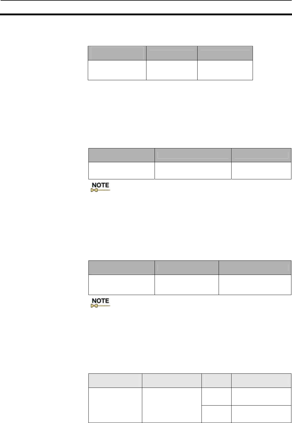
4-3 Reader/Writer Setting 4-3
4-6
1) Communications type setting for COM1 port
Set whether COM1 will be used as RS-232C or RS-485
by using the communications type setting command (CT)
Setting name
(command name) Default set value Setting range
Communications
type setting *1
(CT command) RS-232C RS-232C
RS-485
2) Node No. setting If more than one Reader/Writer is connected to a single host, each
Reader/Writer needs an ID number so that the host can discriminate one
Reader/Writer from another. Such an ID number is called node number.
Each Reader/Writer must be assigned a unique node number. Each
command or response includes the node number of the Reader/Writer.
Communications will not be possible if the node number is wrong.
The setting can be saved by executing the setting write command.
Use the node number setting command (NM) to set a node number.
Setting name
(command name) Default set value Setting range
Node No. setting
(NM command) 00 00∼31
:Communications through COM2 are possible regardless of the node
number setting.
3) Terminal resistance setting This setting is necessary when COM1 is used as RS-485.
If more than one Reader/Writer is connected to a single host, terminal
resistance must be turned on for both the host and the Reader/Writer
connected to either end of the host in order to ensure stable operation.
The setting can be saved by executing the setting write command.
Use the terminal resistance setting command (TM) to set the terminal
resistance.
Setting name
(command name) Default set value Setting range
Terminal resistance
setting
(TM command) OFF ON/OFF
: For more information, refer to 4-6-2-2 RS-485 Interface Cabling.
4-3-2 Chip Operating Mode Setting
This Reader/Writer consists of 2 types of operating modes (hereinafter
called: Operating Mode) in accordance with a type of the Tag (an
incorporated IC chip). Both operating modes must be set in accordance
with the Tag you choose. Execute the Operating Mode Switch Setting
Command (TY)
.
Setting name
(command name) Default set value Setting
range Remarks
ISO
Mode
Conformed to the
ISO/IEC15693 standard
(I.CODE SLI Chip)
Operating Mode
Switch Setting
Command (TY))
ISO Mode [1.20 - ]*
I.CODE1 Mode
[ - 1.10] I.CODE1
Mode I.CODE1 Chip
supported
4-3 Reader/Writer Setting 4-3
4-7
4-3-3 Command Processing Procedure Setting
1)UID/SNR Addition Setting For the Read command response in I.CODE1 Mode or the Read/Write
command response in ISO Mode, whether to add the UID/SNR (a serial
number which is a unique ID given to a Tag) must be selected. When
enabled, this command makes association of data contained in a Tag to
the serial number of that Tag considerably easier.
Make this setting by using the UID/SNR Addition Command (SN)
Setting name
(command name) Default set value Setting range
UID/ SNR addition
setting(SN command))Disable (do not add) Enabled, Disabled
:Note Using Selective Access in ISO Mode when communicating with
specific Tags among the multiple Tags in the communication area is extremely
useful, because data reading and UID acquisition can be processed by a single
command.
2)Discriminating Access to Tag Setting
The discriminating access to the Tags is set using the AFI (ISO Mode) on
the Tags or the Family Code/Application ID (I.CODE1 Mode.) Refer to
SECTION 3-5 for the details of the function.
The settings are done using the specific setting command of each
operating-mode.
Operatin
g mode Setting name
(command name) Default set
value Setting range
Reader/Writer AFI
Enable/Disable
Changeover (AE
Command)
Disabled Enabled,
Disabled
ISO
Reader/Writer AFI Value
Setting (AF Command) 00 00∼FFh
Reader/Writer Family
Code Setting (FC
Command) 00 00∼FFh
I.CODE1 Reader/Writer
Application ID setting
(AI Command) 00 00∼FFh
3)Duplicate Communication Protecting Function
In executing the commands with the options that specify the serial
processing of multiple Tags (FR, MT, MR, and UR [I.CODE1 Mode]), the
function controls the condition so that the Tags with the same UID/SNR
are processed only once. This function is enabled by specifying the
maximum number for the table of the processed Tags. Refer to SECTION
3-8 for the details of the function. This function is specified by the
Duplicate Communication Protecting Function Setting Command (MX.)
Setting name
(command name) Default set value Setting range
Mask Setting (MX
Command) Disabled Enabled (The number of
tables: 1, 4, 8, 16, 32, 64,
128, 256), Disabled
4-3 Reader/Writer Setting 4-3
4-8
4-3-4 Antena and Tag Communications Setting
Set how communications should take place between the Reader/Writer
and a Tag.
1) Reader/Writer-Tag communications speed setting
Set the speed of communications between the Reader/Writer and a Tag
(baud rate from the Reader/Writer to a Tag). The baud rate from a Tag to
the Reader/Writer is fixed (26.5kbps).
This setting can be made by using the Tag Communications mode Setting
Command (CM).
Setting name
(command name) Default set value Setting range
Standard mode
Communications speed
setting(CM command) Fast mode
Fast mode
:The Fast mode, the factory default, is highly recommended
because it provides fast transmission speed for normal use. Its
communication distance, area, and other performance conditions
are same as those in Standard Mode.
2) Receiving antenna setting This is enabled when using the receiving antenna. The antenna is used
for some specific configurations such as those for the gate antennas. Set
the function according to the respective antenna operation guide. The
function must be disabled for the configurations where the antenna is not
used.
This can be done by using the Receiving Antenna Changeover Command
(AC). Setting name
(command name) Default set value Setting
range
Receiving antenna setting
(AC command) Disable (the receiving antenna will
not operate) Enabled,
Disabled
3) I/O Automatic Changeover setting
When the I/O Automatic Changeover Function is enabled, the antenna is
controlled by the I/O Automatic Changeover (OUT3 and OUT4) for
Multiple Repeat (MR) reading, Fast Read Repeat (UR) (I.CODE1 Mode
only), and EAS Check Command (EA) This function should only be
enabled for antennas requiring the I/O automatic changeover. The
function must be disabled for the configurations where the antenna is not
used.
The function is set by the I/O Automatic Changeover Setting Command
(CA) Setting name
(command name) Default set value Setting
range
I/O Automatic
Changeover Setting
Command (CA.)
Disabled(Not Automatic
Changeover setting) Enabled,
Disabled
: The Operation Manual describes what type of antennas
require the receiving antenna settings or I/O automatic
changeover settings. Follow the respective instructions in
setting these functions.

4-3 Reader/Writer Setting 4-3
4-9
4-3-5 Offline Mode Setting
Set whether the Reader/Writer will start in offline mode or online mode.
This setting can be made by using the offline mode setting command (FL)
Setting name
(command name) Default set value Setting
range
Offline Mode Setting
(FL command) Enable (offline mode) Enabled,
Disabled
EAS threshold 75%(4Bh)
25%(19h) 0-100%
(00h∼64h)
OUT1 output time 500 ms (05 h) 100ms-22.5 s
(01h∼FFh)
4-3-6 Initialization of settings
If necessary, you can return all the settings to their default set values.
Use the initialize settings command (IS) to return your settings to their
default set values
Setting name
(command name)
Initialize settings
(IS command)
4-3-7 Fixing of Settings
By fixing the settings that you have made using various setting
commands, you can write them into the EEPROM (nonvolatile memory)
so that they will survive a power reset of the Reader/Writer.
Use the EEPROM write command (EW) to fix your setting
Setting name
(command name)
EEPROM write
(EW command)
Precautions on setting modifications
●The execution of the setting commands only modifies the S-RAM (volatile memory) on the Reader/Writer. The
modifications are not reflected immediately; they are reflected only after the Reset Command (XZ) has been
executed.
●To apply the modified settings at the next startup, fix the settings and reset the power supply. If the settings are
not fixed, the modifications will be reset to the original status after the power supply reset. This does not apply to
the communication settings for COM2.
●If Reset Command (XZ) is executed without fixing the settings, the settings are reset to original status after the
power supply reset.
●The default mode is Offline mode. To change the settings, the mode must be switched to Online mode. Connect the
host and execute Stop Command (ST.)

4-4 Installation Environment 4-4
4-10
The V720S-BC5D4 Reader/Writer is a highly reliable control device
withstanding tough environments. In order to ensure the full, reliable
performance of the RFID system, however, observe the following.
4-4-1 Installation Do not install the Controller under the following conditions.
• The ambient temperature is not within a range between -10℃ and
50 ℃ or there are radical temperature changes resulting in
condensation.
• The humidity is not within a range between 35% and 85%.
• There is corrosive gas, flammable gas, dust, salt, or metal powder.
• The Reader/Writer is affected by direct vibration or shock.
• The Reader/Writer is exposed to direct sunlight.
• Oil, or chemical is sprayed onto the Controller.
• Do not install the Reader/Writer close to heaters, transformers, or
resistors that radiate excessive heat.
• If power lines or high-tension lines with large currents are located
close to the Reader/Writer, be sure to test the Reader/Writer
carefully and make sure that wires connected to the Reader/Writer
are not affected by the noise of power lines or high-tension lines.
Note
●Be sure to abide by the above before installing the Reader/Writer and carefully test the Reader/Writer.
●Be sure to wire antenna cables separately from other cables. For the antenna cable, be sure to use V720-A41
3.35M or V720-A41 10.33M that is specially designed for this product. Using any other cable may affect adversely
the communications performance, waterproof performance, etc.
● For wire power and I/O cables as well, wire them separately wherever possible in order to avoid malfunctions.
Caution
Ensure that a solid (Class D) grounding is established for the “GR” on the Reader/Writer power connector.
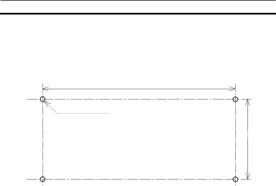
4-5 Mounting Method 4-5
4-11
The Reader/Writer must be mounted using a mounting plate. When
mounting, be sure to secure it onto the mounting plate with M6 screws,
spring washers and flat washers.
Do not apply organic solvent, e.g., screw lock solvent, to the screws to
secure the Reader/Writer. If you do, the Reader/Writer body and the
mounting plate may be damaged.
4-5-1 Mounting Dimensional Drawing
235.5±0.2
4-M6 or 4-φ6.5
102±0.2
4-6 Wiring Method 4-6
4-12
4-6-1 Power Supply and Grounding Wires
● Power cable Power side Reader/Writer side
Connector plug
Connected to Name Pin No.
24 VDC + 24 VDC 2
GR FG 3
0V GND 1
● Recommended Compact DC Power Supply (OMRON)
Model Output capacitance Input voltage
S82K-03024 24VDC at 1.3A 100/200V
Note
● Use 24 VDC to supply power to the Reader/Writer. When you use the recommended power supply, S82K-03024,
and a cable with a thickness of AWG16, the cable can be extended to 7 meters at maximum. If a longer power wire
is desirable, use a power supply with remote sensing function.
● The maximum power consumption of the Reader/Writer is 25 W. An inrush current of approximately 30 A at 24
VDC, however, flows when the Reader/Writer is turned ON. Take this into consideration when preparing the
power supply.
● Provide a power wire with a thickness of AWG16 in order to prevent the dropping of voltage. It is recommended
that twisted-pair wire be used for the power line. The thickness of AWG16 is the maximum wire diameter that
can be used with the power connector of the Reader/Writer.
● Use Class D grounding (previous Class 3 grounding) for the Reader/Writer for improved noise
resistance.
● Use the ferrite core enclosed to the Reader/ Writer for the 100VAC side of the recommended compact
DC power supply S82K-03024.
WARNING
● Be sure to connect to a power supply with a maximum power supply capacity of 24V 4.2A (100 W) or less.
In case a short-circuit failure should occur within the Reader/Writer, a burnout in the power cable may result.
Attach the ferrite core (accessory) for the cable to supply 100VAC.
DC power supply S82K-03024)
AC side DC side
How to attach ferrite core:
Open the ferrite core. Put the cable
inside and roll one time as shown in
the figure. Close the core in the
direction of the arrow and make
sure it locked. Set the core near the
DC power supply side.
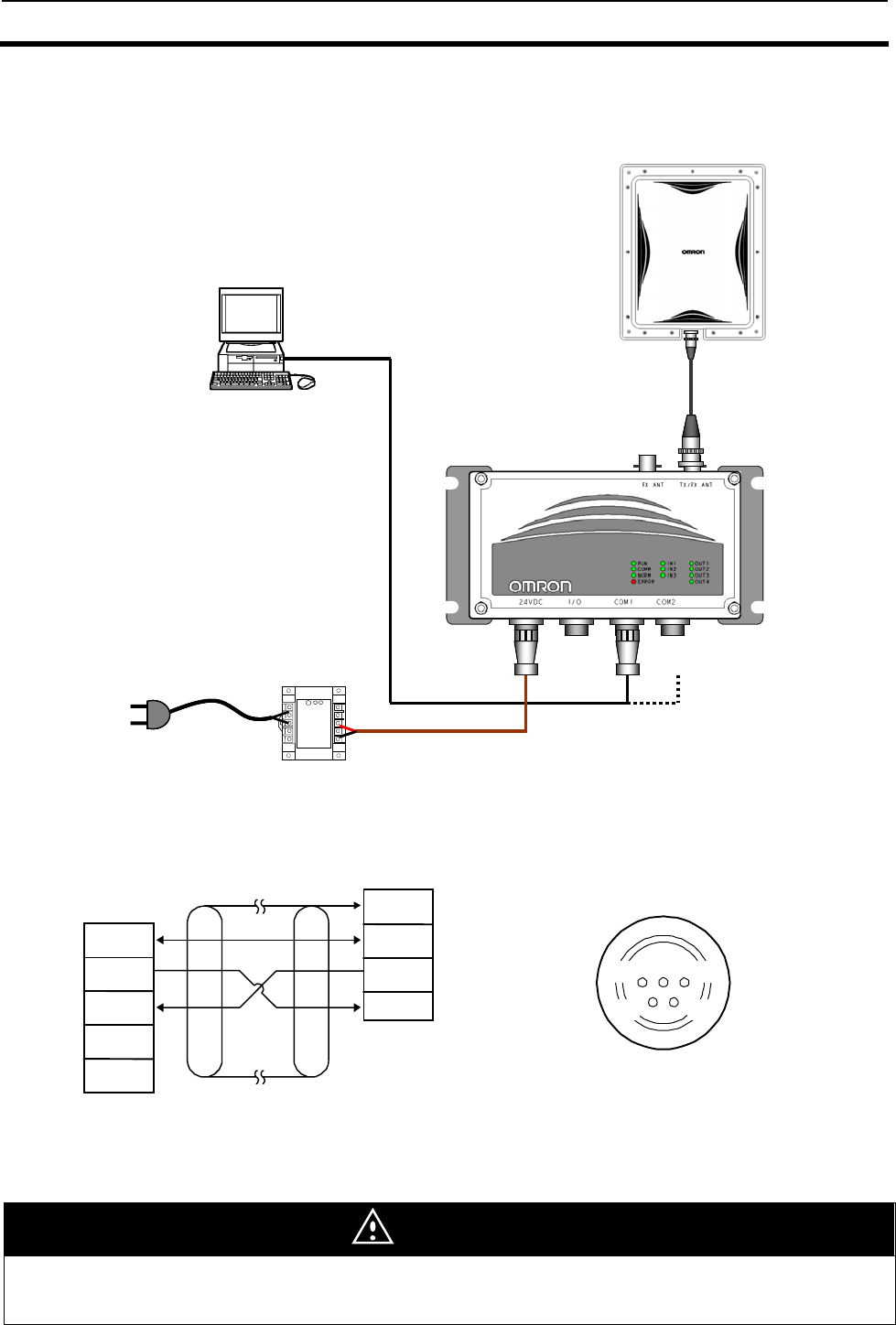
4-6 Wiring Method 4-6
4-13
4-6-2 Host Communications Cabling
4-6-2-1 RS-232C Interface Cabling
RU
N
CO
MM
NO
RM
ER
RO
R
PC
V720-HS04
RS-232C cable
V720-A62
RUN
COMM
NORM
ERROR
AC100V
Power supply
S82K-03024
Power supply cable
V720-A51
Antenna cable
V720-A41
RU
N
CO
MM
NO
RM
ER
RO
R
PC
V720-HS04
RS-232C cable
V720-A62
RUN
COMM
NORM
ERROR
RUN
COMM
NORM
ERROR
AC100V
Power supply
S82K-03024
Power supply cable
V720-A51
Antenna cable
V720-A41
H
os
t
compu
t
er
SG
SD
RD
+
−
FG
SG
SD
RD
3
2
1
4
5 Shield wire
Reder/Write
r
(
COM1, COM2
)
Pin layout when cable connector on
Reader/Writer is viewed from engaging face
2 3
5
4
1
Caution
● The shield wire must always be grounded on the host side.
● Leave the pin for RS-485 unconnected.
● Cables must not be longer than 15 meters.
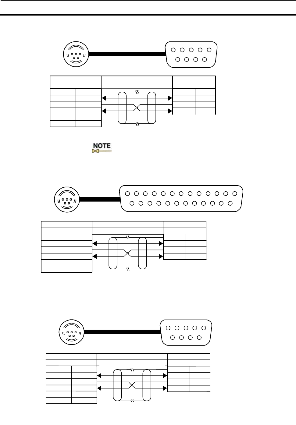
4-6 Wiring Method 4-6
4-14
1) Connection to a DOS/V Host with 9-pin Port
(Pin layout when cable connector is viewed from engaging face)
:Connect the shield wire to the connector cover on the PC side.
2) Connection to Host through NEC 98 or Compatible Computer, 25-pin Port
(Pin layout when cable connector is viewed from engaging face)
3) Connection to OMRON C200H PLC
(Pin layout when cable connector is viewed from engaging face)
リーダライタ
COM1、COM2 接続機器 98互換パソコン
ケーブルに付いたコネクタ
(シールド線)
25ピン、オス
3SG
2SD
1RD
4+
5−
SG
GR 7
1
SD 2
RD 3
RS 4
CS 5
113
14 25
123
54
Reader/Write
r
Connectin
g
Device
Connector of cable
COM1
,
COM2
NEC98 Compatible PC
25-
p
in
,
male
Shield wire
2 3
4
リーダライタ
C O M 1 、CO M 2 接続機器 形 C200H-ASC02
ケーブルに付いたコネクタ
(シールド線)
9 ピン、オス
3 S G
2 S D
1 R D
4 +
5 −
SG
GR 9
1
SD 2
RD 3
RS 4
CS 5
1 5
6 9
Reader/Writer Connecting Device
Connector of cable
COM1
,
COM2
C200H ASC02
9-
p
in
,
male
Shield wire
1 5
リーダライタ 接続機器 DOS/Vパソコン
ケーブルに付いたコネクタ
(シールド線)
9ピン、メス
3SG
2SD
1RD
4+
5−
SG
GR 5
SD 3
RD 2
RS 7
CS 8
1
5
6
9
123
54
Shield wire
Reader/Write
r
Connectin
g
Device
Connector of cable
COM1
,
COM2
DOS/V PC
9-
p
in
,
female
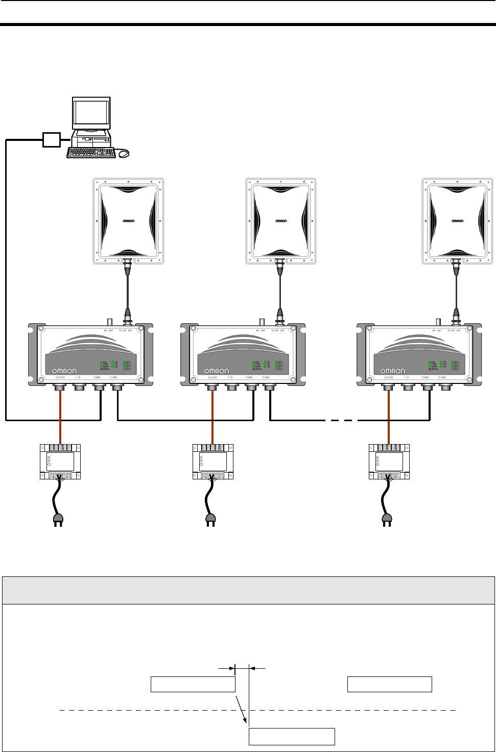
4-6 Wiring Method 4-6
4-15
4-6-2-2 RS-485 Interface Cabling
Note
On the host side, send the following commands after confirming that the Reader/Writer responds normally.
Do not begin sending commands until the host is completely ready for transmission. Switch the host to receive
mode within 5 ms after completion of transmission of commands. If you fail to do this, the host may not be able to
communicate with the Reader/Writer.
上位機器
5ms
形V720-BC5D1
コマンドフレーム コマンドフレーム
レスポンスフレーム
Host Command frame
V
720S-BC5D4A
Command frame
Response frame
RU
N
CO
MM
NO
RM
ER
RO
R
PC
V720-HS04
Setup
・Node NO. 00
・Terminating
resistor OFF
RS-485 connection
cable
RS-485
AC100V
RU
N
CO
MM
NO
RM
ER
RO
R
V720-HS04
AC100V
RU
N
CO
MM
NO
RM
ER
RO
R
V720-HS04
AC100V
DC24V
power supply DC24V
power supply DC24V
power supply
RS-485 connection cable
RS232C/485
converter
Antenna cable
V720-A41 Setup
・Node NO. 01
・Terminating
resistor OFF
Setup
・Node NO. 31
・Terminating
resistor ON
RU
N
CO
MM
NO
RM
ER
RO
R
PC
V720-HS04
Setup
・Node NO. 00
・Terminating
resistor OFF
RS-485 connection
cable
RS-485
AC100V
RU
N
CO
MM
NO
RM
ER
RO
R
V720-HS04
AC100V
RU
N
CO
MM
NO
RM
ER
RO
R
V720-HS04
AC100V
DC24V
power supply DC24V
power supply DC24V
power supply
RS-485 connection cable
RS232C/485
converter
Antenna cable
V720-A41 Setup
・Node NO. 01
・Terminating
resistor OFF
Setup
・Node NO. 31
・Terminating
resistor ON
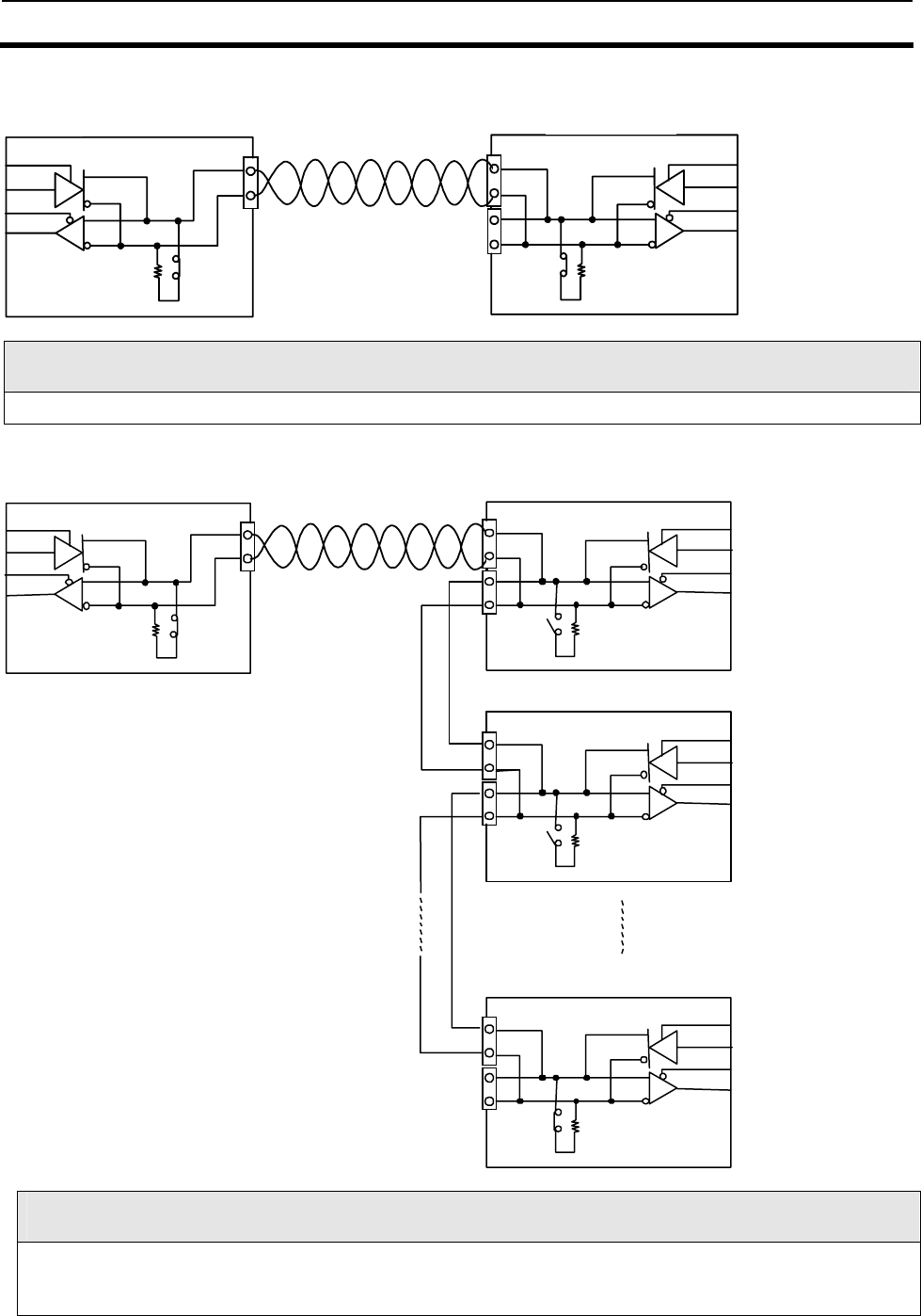
4-6 Wiring Method 4-6
4-16
1) Example of wiring for 1-to-1 connection
Note
Be sure to turn on the terminal resistance on both the host and Reader/Writer sides.
2) Example of wiring for 1-to-N connection
Terminal resistance setting
When you connect more than one Reader/Writer, turn on the terminal resistance for the Reader/Writer that is
located farthest from the host and the terminal resistance for the host. The terminal resistance for all the other
Reader/Writers must be off.
+
−
上位機器
4
5
4
5
COM1 V720-BC5D1
COM2
終端抵抗 2 2 0 Ω
あり 終端抵抗220 Ω
あり
+
−
4
5
4
5
COM1
C0M2
COM1
COM1
COM2
COM2
4
5
4
5
4
5
4
5
Second
Reader/Writer
First Reader/Writer
Nth Reader/Writer
(max. 31)
Terminal
resistance 220Ω
V720S-BC5D4A
Terminal
Resistance 220
Terminal
resistance
220
Ω
V720S-BC5D4
V720S-BC5D4A
Terminal
resistance
220
Ω
Host
V720S-BC5D4A
V720S-BC5D4A
Host
Terminal resistance
220Ω is on
Terminal resistance
220Ω is on
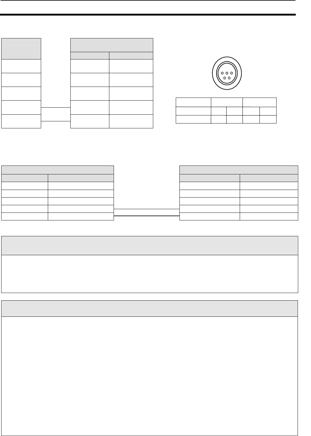
4-6 Wiring Method 4-6
4-17
■ Example of wiring between host and Reader/Writer
Host side Reader/Writer side
Connector plug
(accessory)
Connected to Name Pin number
RD 1
SD 2
SG 3
+ + 4
- - 5
■ Example of cabling between Reader/Writers
Reader/Writer side (COM1) Reader/Writer side (COM2)
Connector plug (accessory) Connector plug (accessory)
Name Pin number Name Pin number
1 RD RD 1
2 SD SD 2
3 SG SG 3
4 + + 4
5 - - 5
Note
● Leave the pin for RS-232 unconnected.
● Be sure to use a twisted-pair wire for the signal line.
● Be sure to use a wire with a thickness of AWG20 for the signal line.
● When you use a shielded cable, be sure to ground on the host side.
● Make sure that the total cable length for 1-to-1 and 1-to-N connection is not longer than 300 m.
Note
When you connect more than one Reader/Writer, give special attention to communications timing
between Reader/Writers. To ensure proper timing, you will need to perform both theoretical calculation
of timing and verification of communications on real machines.
1) The Reader/Writers cannot operate simultaneously except through polling-related commands.
This means that, even when you connect more than one Reader/Writer, only one Reader/Writer
can communicate with the host at a time.
Multiple Reader/Writers can access the host only in a time-phased manner.
2) When you use an Auto command, the Reader/Writer will not return a response but continue to
wait if there are no Tags in the communications area. In this state, if you send a command to
another Reader/Writer, no command will be accepted until a response is returned. To avoid this,
you must abort the Auto command using the STOP command before sending any command.
3) Polling-related commands do not support any commands but Auto commands. These commands
are not available in Multiple Access Mode (which permits access to multiple Tags) to avoid
processing complexities.
2 3
4
1
5
Pin layout when cable connector on
Reader/Writer is viewed from engagingface
4
+-
4
+ -
Port
Terminal No.
Polarity.
COM1 COM2
5 5
* Short circuits have been established within RS-485
between Pin 4 of COM1 and Pin 4 of COM 2 and
between Pin 5 of COM2 and Pin 5 of COM1.
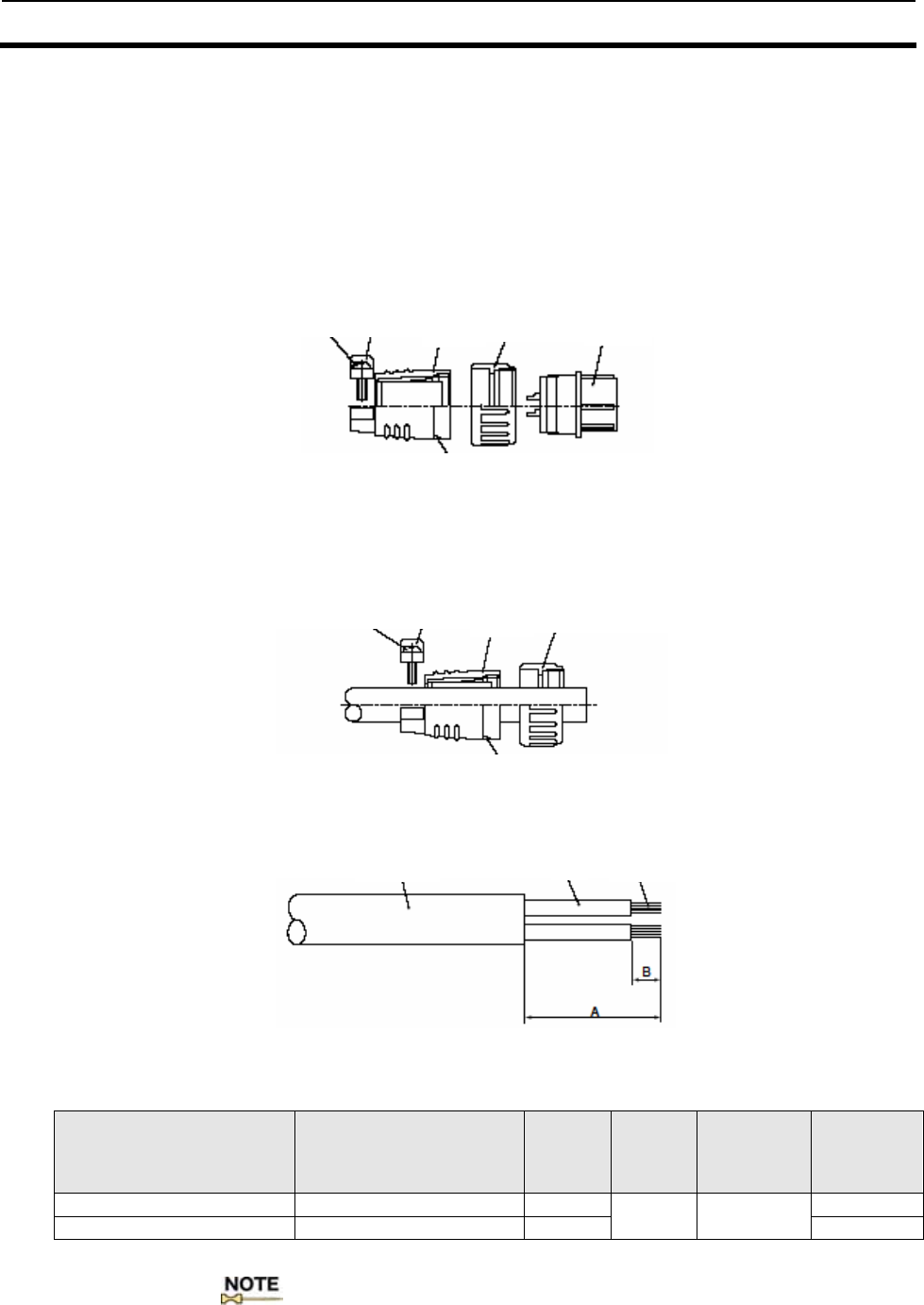
4-6 Wiring Method 4-6
4-18
4-6-3 Assembly of Connector
4-6-3-1 Assembly of Host Communications Connector and I/O Connector
1) Disassemble the connector as follows:
(1) Loosen the set screw and remove the barrel from the end bell (by
turning it counterclockwise).
(2) Loosen the clamp screw, remove the clamp saddle from the end
bell.
2) Draw the cable through the disassembled parts in the order shown
below.
・ Make sure that the parts are in the correct order and orientation.
3) Strip a part of the sheath and insulator of each cable to be used
according to the measurements specified in the table below.
• Cable terminal treatment measurement table
Usage Connector name
Mesure-
ment A
(mm)
Mesure-
ment B
(mm)
Conductor
cross-sectio
nal area
(mm2)
Iron tip
temperatur
e(%)
Host communications/IO NJC-165 - PF, PM, AdF 16 280
Power supply NJC-2010 - PF, PM, AdF 18 3.2 0.5 350
4) Pre-solder the conductors complete with terminal treatment.
:
• Be careful not to pre-solder the cable cladding.
• When finished, the pre-soldered part should be smaller in diameter
than the contact hole and have no uneven portion on the entire surface.
Clamp nut Clam
p
saddle
End bell Coupling nut Barrel
Setscrew
Clamp nut Clam
p
saddle
End bell Coupling nut
Setscrew
Sheath Conductor
Wire
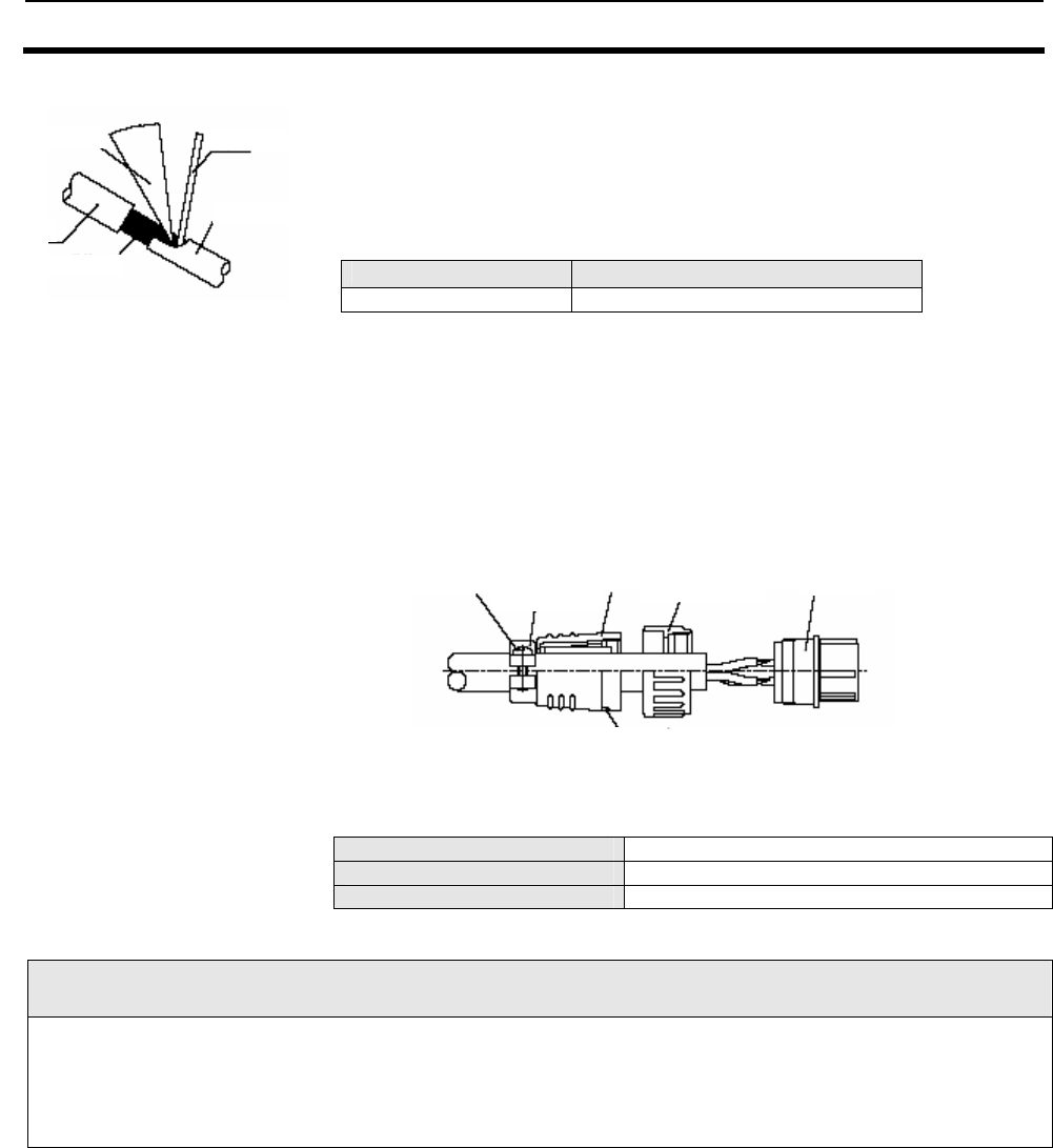
4-6 Wiring Method 4-6
4-19
5) Soldering
Soldering iron to use Conductor cross-sectional area (mm2)
30W 0.5
6) Reassemble the connector as follows.
(1) Put the coupling nut with directing its thread to the connecting
side over the barrel.
(2) Screw the end bell and torque it to the specified values.
(3) Tighten the setscrew to the specified torque value.
(4) Tighten the clump nut to the specified torques value and attach
the clamp saddle to the end bell.
• Tightening torque for screws Unit:N•m
End bell 1.0 - 1.5
Clamp nut 0.4 - 0.6
Set Screw 0.2 - 0.3
Connector models
Model name of connector plug for host communications: NJC-165-PM from Nanaboshi Electric Mfg. Co., Ltd.
Model name of I/O connector plug: NJC-2010-PM from Nanaboshi Electric Mfg. Co., Ltd.
Before use, be sure to check for the proper torques of the cable of your choice. OMRON does not offer any guarantee
for customer-made cables. Please inquire to the manufacturer for details of these connectors.
(1) Insert the pre-soldered wire into the solder pot of the contact.
(2) Heat the contact and the conductors with a soldering iron.
(3) Pour solder to fill the opening between the contact and the
conductors.
Clamp nut
Clamp saddle
End bellCoupling nut Barrel
Setscrew
Solde
r
Wire Contact
Iron tip
Conductor
5-1
SECTION 5
Control from Host
5-1 Control by Commands .............................................................................................5-3
5-1-1 Control by Commands ..........................................................................................5-3
5-1-2 Command-Response Flow ....................................................................................5-3
5-1-3 ACK/NACK Control..............................................................................................5-4
5-2 Control Procedures for Each Communication Mode ..............................................5-5
5-2-1 Single Access .........................................................................................................5-5
5-2-1-1 Single Trigger Mode ...................................................................................5-5
5-2-1-2 Single Auto Mode........................................................................................5-5
5-2-1-3 Single Repeat Mode: ISO Mode .................................................................5-6
5-2-1-4 Polling Auto Read .......................................................................................5-7
5-2-2 FIFO Access ..........................................................................................................5-8
5-2-2-1 FIFO Trigger Mode.....................................................................................5-8
5-2-2-2 FIFO Auto Mode .........................................................................................5-9
5-2-2-3 FIFO Repeat Mode ...................................................................................5-10
5-2-3 Multiple Access ...................................................................................................5-11
5-2-3-1 Multiple Trigger Mode .............................................................................5-11
5-2-3-2 Multiple Repeat Mode ..............................................................................5-13
5-2-4 Selective Access...................................................................................................5-14
5-2-4-1 ISO Mode...................................................................................................5-14
5-2-4-2 I.CODE1 Mode..........................................................................................5-16
5-2-5 Specifying a Tag Code: I.CODE1 Mode .............................................................5-18
5-3 Command-Response Format .................................................................................5-19
5-3-1 Command Frame Structure ...............................................................................5-19
5-3-2 Response Frame Structure.................................................................................5-19
5-3-3 Command Code List ...........................................................................................5-20
5-3-4 Communication Mode List .................................................................................5-21
5-3-5 Command-by-Command Communication Mode List .......................................5-23
5-3-6 Specifying a Data Code.......................................................................................5-24
5-3-7 Response Code List.............................................................................................5-25
5-3-7-1 ISO Mode...................................................................................................5-25
5-3-7-2 I.CODE1 Mode..........................................................................................5-26
5-3-8 Example BCC Calculation..................................................................................5-27
5-4 Communication Commands ..................................................................................5-28
5-4-1 Read (RD) ............................................................................................................5-28
5-4-2 Write (WT)...........................................................................................................5-29
5-4-3 Read (RD)-Tag Detection: I.CODE1 Mode only................................................5-31
5-4-4 Read (RD)-UID Select/Specified Tag .................................................................5-32
5-4-5 Write (WT)-UID Select/Specified Tag................................................................5-33
5-4-6 Read (RD)-Fast Read Access: I.CODE1 Mode only ..........................................5-34
5-4-7 Polling Single Auto Read (PR) ...........................................................................5-35
5-4-8 Polling Single Auto Write (PW) .........................................................................5-36
5-4-9 Polling Check (PC)..............................................................................................5-37
5-4-10 Polling End (PE)..................................................................................................5-38
5-4-11 Memory Check (MC): I.CODE1 Mode only .......................................................5-39
5-4-12 Memory Calculation (MK): I.CODE1 Mode only ..............................................5-39
5-5 System Command..................................................................................................5-40
5-5-1 System Read (SR): ISO Mode only.....................................................................5-40
5-5-2 System Write (SW): ISO Mode only...................................................................5-41
5-2
5-5-3 System Lock (SL): ISO Mode only..................................................................... 5-42
5-5-4 Read (RD)-SNR Read: I.CODE1 Mode only...................................................... 5-43
5-5-5 EAS Setting (ES): I.CODE1 Mode only ............................................................ 5-44
5-5-6 QuietBit Setting (QB): I.CODE1 Mode only..................................................... 5-44
5-5-7 Lock Setting (LK): ISO Mode............................................................................. 5-45
5-5-8 Lock Setting Read (LR): ISO Mode only ........................................................... 5-46
5-5-9 Lock Setting (LK): I.CODE1 Mode.................................................................... 5-47
5-5-10 EAS Check (EA).................................................................................................. 5-48
5-6 Reader/Writer Control Commands....................................................................... 5-49
5-6-1 Stop (ST) ............................................................................................................. 5-49
5-6-2 Reset (XZ)............................................................................................................ 5-49
5-6-3 ACK (AK) ............................................................................................................ 5-49
5-6-4 NACK (NK)......................................................................................................... 5-49
5-6-5 I/O Control Command (CC) ............................................................................... 5-50
5-6-6 Test (TS).............................................................................................................. 5-50
5-6-7 Version (VS)........................................................................................................ 5-51
5-7 Setting Command ................................................................................................. 5-52
5-7-1 Reader/Writer AFI Enable/Disable Changeover (AE): ISO Mode only........... 5-52
5-7-2 Reader/Writer AFI Value setting (AF): ISO Mode only................................... 5-52
5-7-3 Reader/Writer Family Code Setting (FC): I.CODE1 Mode.............................. 5-53
5-7-4 Reader/Writer Application ID Setting (AI): I.CODE1 Mode ........................... 5-53
5-7-5 UID/SNR Addition Setting (SN)........................................................................ 5-54
5-7-6 Node Number Setting (NN) ............................................................................... 5-55
5-7-7 Communications Port Setting (CP)................................................................... 5-56
5-7-8 Communications Type Setting (CT).................................................................. 5-58
5-7-9 Tag Communications Mode Setting (CM)......................................................... 5-58
5-7-10 Antenna Changeover (AC) ................................................................................. 5-59
5-7-11 Terminal Resistance Setting (TM) .................................................................... 5-59
5-7-12 Offline Mode Setting (FL) .................................................................................. 5-60
5-7-13 Set Value Initialization (IS)............................................................................... 5-61
5-7-14 Set Value Writing (EW) ..................................................................................... 5-61
5-7-15 Chip Operating Mode Switch (TY) .................................................................... 5-62
5-7-16 Duplicate Communication Protecting Function Setting (MX) [Ver1.20 and higher] .. 5-63
5-7-17 I/O Automatic Changeover Setting (CA) [Ver1.20 and higher]....................... 5-64
5-8 Other Commands .................................................................................................. 5-65
5-8-1 Command Undefined Response......................................................................... 5-65
5-9 Command Connection: I.CODE1 Mode only.............................................................. 5-67
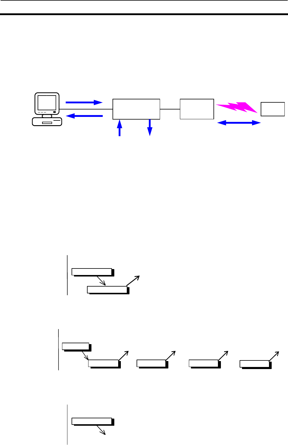
5-1 Control by Commands 5-1
5-3
5-1-1 Control by Commands
The Reader/Writer operation is controlled by the commands from the connected host. The result of the
command execution is returned as a response.
In Online Mode, all the operations, such as Tag-data Reading/Writing, Tag-function setting, operating
condition setting, or Reader/Writer function control, are controlled by the commands.
In Offline Mode, the Reader/Writer functions controlled by the commands are restricted to those
controlled by Stop and Reset commands. The operating conditions for Offline Mode are set in Online Mode.
5-1-2 Command-Response Flow
In Online Mode, the host sends an instruction command and the Reader/Writer returns the result as a
response. The command-response flows vary, depending on the types of commands and specified
communications, as shown below.
1-to-1 Response
One response is returned per command for Single Trigger (ST), Single Auto (SA), FIFO Trigger (FT), FIFO
Auto (FA), UID Select (SL), or Tag Designation is specified for the command that performs the
communication with the Tag, or when a command that does not perform the communication with the Tag
is specified.
Host
Reader/Writer
Command
Response
Multiple Response
Multiple Responses are returned per command for Single Repeat (SR), FIFO Repeat (FR), Multiple
Trigger (MT), Multiple Repeat (MR), or Tag Detection (LT) is specified for the command that performs the
communication with the Tag.
Host
Reader/Writer Response
Command
Response Response Response
No response
When the Reader/Writer receives the Reset Command(XZ), it is reset without returning a response and
waits for the next command.
Host
Reader/Writer
Command
Reset
Reader/Writer Antenna Tag
Host device (PC)
Command
(
direction
)
(1)
Communication with ta
g
General input General output
Response
(
result
)
(2) Operation
condition setup
(3) Function control
(functions such as process
stop or output setup)
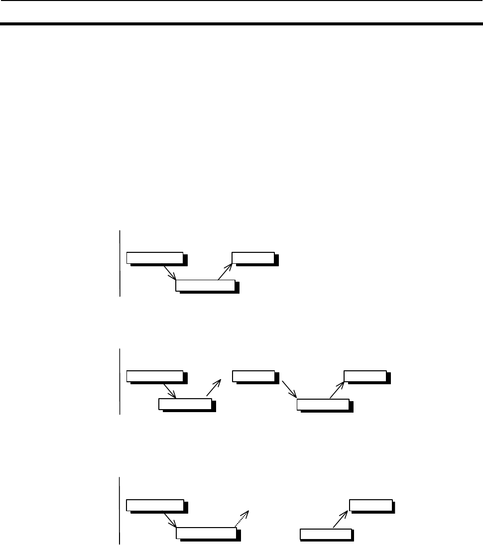
5-1 Control by Commands 5-1
5-4
5-1-3 ACK/NACK Control
When using ACK/NACK control, if the host does not receive a normal response, the Reader/Writer will
resend the response by either (1) when the host sends a NACK command to the Reader/Writer or (2) when
there is no response within a set period of time. Consequently, a response can be received without
communicating with a Tag again. The host checks that responses have been received normally using the
ACK/NACK commands, so response data can be communicated dependably.
■Using ACK/NACK Control
If the host receives a normal response, it sends an ACK command to the Reader/Writer. The
Reader/Writer judges that the host has received a normal response, and enters a command-waiting state.
If, after the Reader/Writer has sent the response, an ACK is not received normally within the time set
using the time out setting, or a NACK is received, the Retry Flag is set and the last response is sent again.
The maximum number of response retries that can be made is nine.
Host Receives a Normal Response and Sends ACK Command
Host
Reader/Writer Response
Command ACK
Host Cannot Receive a Normal Response and Sends a NACK Command
Error occurs
Host
Reader/Writer Response
Command NACK ACK
Retry
Response
Host Did Not Send an ACK/NACK Command within the Timeout Period
Host
Reader/Writer Response
Command ACK
Retry
Response
Timeout
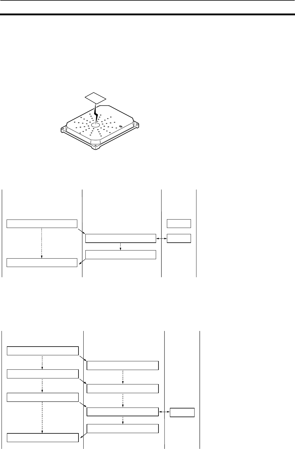
5-2 Control Procedures for Each Communication 5-2
5-5
The operating sequences including the communication with the Tag or timing for returning the response
vary, depending on the communication mode. The communication mode is set by specifying the
communication mode in the command data. The access and mode specified as the communication settings
must be those specifiable for each Tag status in the specified antenna’s communication area or the
connection topology with the host. This section describes these access and mode settings.
5-2-1 Single Access
In single access, a single Tag can exist in the communications area. The presence of two or more Tags in
the communications area causes a communications error.
5-2-1-1 Single Trigger mode
Single Trigger mode is used when a single Tag is present in a resting condition in the antenna
communication area. If the Tag does not exist in the antenna communication area, No Tag
Error is returned.
Trigger command
(Host) (Reader/Writer) (Tag)
Yet to enter
Communications Tag
Tag
(Stationary)
(Stationary)
Send a response
Command end
(1) Sends a commands if a Tag is in the R/
W
A
ntenna’s communication range.
(2) The Reader/Writer communicates
according to the command.
(3) On completion of communications, the
Reader/Writer returns a response to the
host.
5-2-1-2 Single Auto Mode
The Reader/Writer waits until the Tag has entered the antenna communication area and
executes the command it received from the host. When the Reader/Writer receives Auto
Command, it enters the busy state until the communication with the Tag has been completed,
during which it does not accept any commands other than Stop Command (ST) and Reset
Command (XZ).
Auto command
(Host) (Reader/Writer) (Tag)
Waits for a Tag to enter Yet to enter
Busy
Command end
Communications process Tag
Passes
Send a response
(1) The Reader/Writer receives
a command.
(2) It waits for a Tag to enter the
R/W Antenna’s communication
area.
(3) When a Tag enters the area,
it communicates with the Tag.
(4) On completion of communications,
it returns a response to the host.
Busy
Waits for a Tag to enter Yet to enter
5-2 Control Procedures for Each Communication 5-2
5-6
5-2-1-3 Single Repeat Mode: ISO Mode
The Reader/Writer waits for a Tag to enter the R/W Antenna’s communications area. Every
time a Tag enters the communications area, the Reader/Writer communicates with the Tag and
returns a response. It is not until communications are stopped by the Stop(ST) or Reset(XZ)
command that the Reader/Writer accepts the next command.
Operation in I.CODE1 mode
● Do not operate the function in I.CODE1 mode. If a function equivalent to ISO mode, i.e., a function that
always returns a response, is required for the area confirmation and other purposes, a single command (Tag
code = 0) by Fast Read Access should be used.
(If the function is executed in I.CODE1 mode, the Reader/Writer will perform the process only once at the Tag’s
entry to the communication area and return a response. Multiple Tags in the communication area may result in a
response with abnormal read data).
(Tag)(Reader/Writer)
Receives a response (Tag 1)
Receives a response (Tag 1)
(Host)
Waits for a Tag to approach
(4) The Reader/Writer continues
communicating with the Tag while the
Tagisinthecommunicationarea,and
(1) The Reader/Writer receives a command.
Single Trigger Command
Tag detection
Response
Tag detection n
Response
Waits for a Tag to approach
(3) When a Tag approaches the Reader/Writer, it
with the Tag and returns a response.
(2) The Reader/Writer launches the
communication with a Tag, and waits for a
Tt h
Tag 1
Tag detection Tag 2
Receives a response (Tag 2)
Response
Waits for a Tag to approach
(5) After the Tag in the communication
area has been cleared, the Reader/Writer
(6) When the next Tag approaches the
communication area, the Reader/Writer
(7) The Reader/Writer repeats the
performance until the operation is
(1)The Reader/ Writer receives a command
(2)The Reader/Writer launchesthe
communication with a Tag, and waits for
a Tag to approach.
(3) When a Tag approaches the Reader/Writer,
it with the Tag and returns a response.
(4)The Reader/Writer continues communicating
with the Tag while the Tag is in the communication
area, and returns a response.
(5) After the Tag in the communication
area has been cleared, the Reader/Writer
waits for the next Tag to approach.
(6) When the next Tag approaches the
communication area, the Reader/Writer
once again communicates with the Tag
and returns a response.
(7) The Reader/Writer repeats the performance
until the operation is terminated by the Stop
Command (ST).
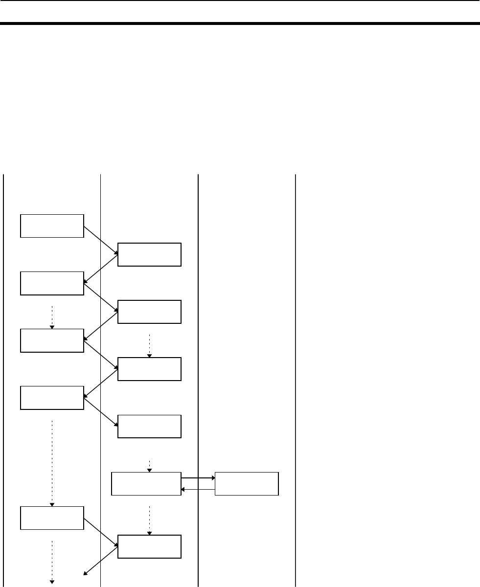
5-2 Control Procedures for Each Communication 5-2
5-7
5-2-1-4 Polling Auto Read
If an Auto command is used when a single host controls more than one Reader/Writer, the
communications path between the host and one of the Reader/Writers to which the command is
sent becomes busy, disabling the host to control other Reader/Writers. On the other hand,
when a Polling Auto command is sent instead, the Reader/Writer returns a response according
to the request from the host. The communications line with the host will not remain busy,
allowing the host to send a command to other Reader/Writers. When Polling Auto command is
executing, the only commands accepted and executed are Polling Check (PC), Polling End (PE),
Reset Command (XZ), and Stop Command (ST). An example of Polling Auto Command
executed for two Reader/Writer devices are shown below.
(1) The host sends the Polling Auto
Command to the Node 1
Reader/Writer.
(2) Immediately after command reception,
Node 1 returns a response indicating
the acceptance of the command.
(3) The host sends the Polling Auto
Command to Node 2.
(4) Immediately after command reception,
Node 2 returns a response indicating
acceptance of the command.
(5) The host inquires after the progress of
the communications processing or
stops the Polling Auto processing
using the Polling sub command. When
the communications processing is not
yet complete, the Reader/Writer
returns a response indicating
unfinished processing in reply to the
inquiry of the Polling sub command.
(6) The Node 1 communicates with a Tag
entering the communications area.
(7) Node 1 returns a response indicating
the results of communications with the
Tag in reply to the Polling
subcommand.
(Tag) (Reader/Writer) (Host)
Response
Polling Auto
Command
Node 1
Response Yet to enter
Node 2
Node 2
Response
Polling
subcommand
pass
Node 1
Node 1
Yet to enter.
Passing in front of Node
1’s antenna
Referring to Node 1
Response Yet to enter
Node 2
Yet to enter
Referring to Node 2
Response Ta
g
(
2
)
Response
Communications
processing by Node 1 is
complete.
Referring to Node 1
Polling Auto
Command
Polling
subcommand
Polling
subcommand
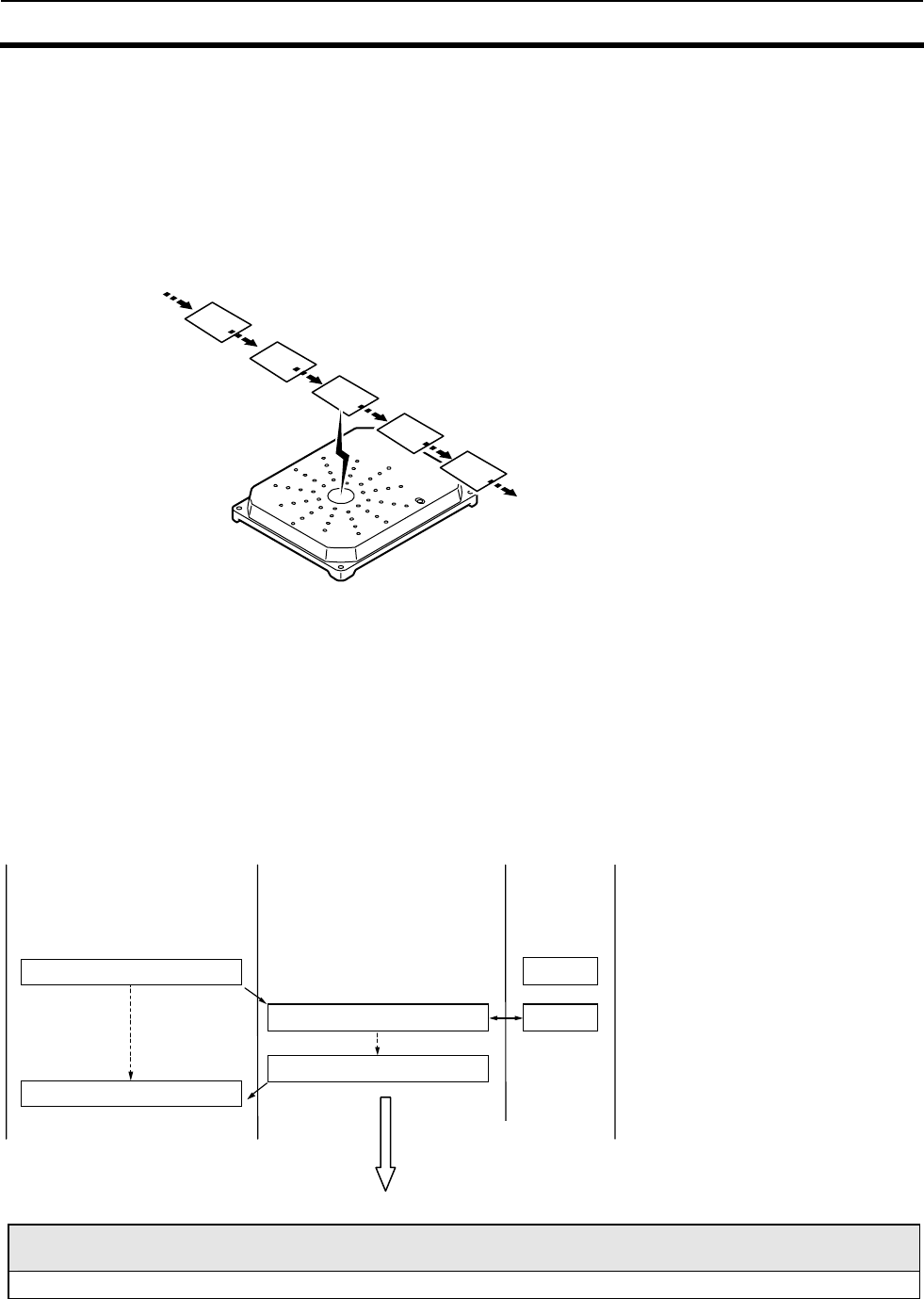
5-2 Control Procedures for Each Communication 5-2
5-8
5-2-2 FIFO Access
In FIFO (first-in, first-out) access, communications with Tags entering the communications area one after
another are carried out in sequence. Once communications with Tags are completed, access to them is
prohibited. Consequently, even if Tags with which communications are already completed exist in the
communications area, a newly entering Tag can be accessed. Simultaneous entering of two or more Tags
causes a communications error. Once an access-prohibited Tag leaves the communications area, access to
the Tag is enabled again.
5-2-2-1 FIFO Trigger Mode
FIFO Trigger Mode is used for communications when the Tag is present in a resting condition
in the antenna communication area. The Reader/Writer prohibits access to the Tag after the
communication has been completed, and keeps the antenna oscillated to maintain the FIFO
access. Under such conditions, the Reader/Writer can issue another FIFO command and
communicate with the next Tag that enteres the communication area, where the previous Tag
with which the communication has been completed is still present. (The commands other than
FIFO Access are rejected).
When there are no accessible Tags in the antenna communication area, the No Tag Error is
returned.To exit the FIFO state, execute Stop Command (ST).
Trigger command
(Host) (Reader/Writer) (Tag)
Yet to enter
Communications Tag
Tag
(Stationary)
(Stationary)
Send a response
Command end
(1) Sends a commands if a Tag is in the R/
W
A
ntenna’s communication range.
(2) The Reader/Writer communicates
according to the command.
(3) On completion of communications, the
Reader/Writer returns a response to the
host.
Note:
Before entering Trigger mode, make sure the Tag is in a resting condition in the antenna communication area.
FIFO 継続状態
(Host) (Reader/Writer)
FIFO access is maintained.
(3). After the communication has been
completed, the Reader/Writer returns a
response to the host. FIFO access is
maintained.
5-2 Control Procedures for Each Communication 5-2
5-9
5-2-2-2 FIFO Auto Mode
The Reader/Writer waits until the Tag has entered the antenna communication area and
executes the command it received from the host. The Reader/Writer prohibits access to the Tag
after the communication has been completed, and keeps the antenna oscillated to maintain the
FIFO access. Under such conditions, the Reader/Writer can issue another FIFO command and
communicate with the next Tag that entered the communication area where the previous Tag
with which the communication has been completed is still present. (The commands other than
FIFO Access are rejected).
When the Reader/Writer receives Auto Command, it enters the busy state until the
communication with the Tag has been completed, during which it does not accept any
commands other than Stop Command (ST) and Reset Command (XZ). To exit the FIFO state,
execute Stop Command (ST).
オートコマンド
タグ接近待ち
タグ接近待ち
交信処理
レスポンス
(上位機器) (リーダライタ) (タグ)
未接近
タグ
ビジー状態
ビジー状態
コマンド終了
未接近
通過
①リーダライタがコマンドを受信します。
②R/W アンテナの交信領域内にタグが入る
のを待ちます。
③タグが R/W アンテナの交信領域内に入る
とリーダライタはタグと交信を行います。
④交信が終了した後、リーダライタは上位機
器にレスポンスを返します。
Note:
Note, that in Auto mode, the communication path between the Reader/Writer and the host are busy until the Tag
is close to the area; the host cannot send the next command under such conditions.
FIFO 継続状態
FIFO access is maintained.
(1)The Reader/Writer receives a
command.
(2)The Reader/Writer waits for a Tag
to enter the Reader/Writer antenna
communication area.
(3)When the Tag enters the
Reader/Writer antenna communication
area, the Reader/Writer communicates
with the Tag.
(4)After the communication has been
completed, the Reader/Writer returns a
response to the host. FIFO access is
maintained.
(Host) (Reader/Writer) (Tag)
Waits for a Tag to approach
Waits for a Tag to approach
Busy
Busy
Communication process
Response Passes
Yet to
approach
Yet to
approach
Auto Command
Command ends.
Tag
5-2 Control Procedures for Each Communication 5-2
5-10
5-2-2-3 FIFO Repeat Mode
The Reader/Writer waits until the Tag has entered the antenna communication area and starts
communicating. It communicates with the Tags serially as they enter the antenna
communication area, and returns the responses. When the communication has been completed,
the Reader/Writer makes the Tag inaccessible, so that it can communicate with the next Tag
that entered the area although the Tags with which the Reader/Writer has completed the
communication are still present in the same area.
This state continues until the communication has been terminated by Stop Command (ST), or
Reset Command (XZ), and other commands are rejected.
タグ接近待ち
タグ接近待ち
タグ接近待ち
交信処理
レスポンス
タグ接近待ち
レスポンス受信
リピートコマンド
ビジー状態
ビジー状態
ビジー状態
未接近
(上位機器) (リーダライタ) (タグ)
①R/W アンテナの交信領域内にタグが入る
のを待ちます。
②タグが R/W アンテナの交信領域内に入る
とリーダライタはタグと交信を行います。
③交信が終了するとレスポンスを返信しま
す。
その後、再度 R/W アンテナの交信領域内
にタグが入るのを待ちます。
④再度タグが R/W アンテナの交信領域内に
入ると交信を行います。
交信処理 タグ(1)
タグ(2)
ビジー状態
ビジー状態
レスポンス
未接近
通過
未接近
通過
未接近
レスポンス受信
When the Tag is on the boundary of the communication area or enters the communication area
more than once because of swing, the Tag may be processed more than once, or some Tags may
not be processed.
In this case, enable the Duplicate Communication Protecting Function (Table number = 1). The
function will prevent the Reader/Writer from communicating with the Tags already
communicated with, and allows proper and sequential Tag processing.[Software Ver 1.20 and
higher only]
Note
To send another command from Repeat Mode, be sure to use either the stop command or reset command, and
make sure that the Reader/Writer has finished processing commands and is in command waiting status before
sending the new command.
Waits for a Tag to approach
Waits for a Tag to approach
Communication process
Response
Receives a response
Waits for a Tag to approach
Repeat Command
Busy
Busy
Busy
Busy
Receives a response
Busy
Waits for a Tag to approach
Communication process
Response
(Host) (Reader/Writer) (Tag)
(1) Waits for a Tag to enter the
Reader/Writer antenna
communication area.
(2)When a Tag enters the Reader/Writer
antenna communication area, the
Reader/Writer communicates with the Tag.
(3)When the communication has been completed,
the Reader/Writer returns a response.
Then it waits for the next Tag to enter the
Reader/Writer antenna communication area.
(4) When the next Tag enters the
Reader/Writer antenna
communication area, the
Reader/Writer communicates with
the Tag.
Ta
g
(
1
)
Ta
g
(
2
)
Passes
Passes
Yet to
approach
Yet to
approach
Yet to
approach
Yet to
approach
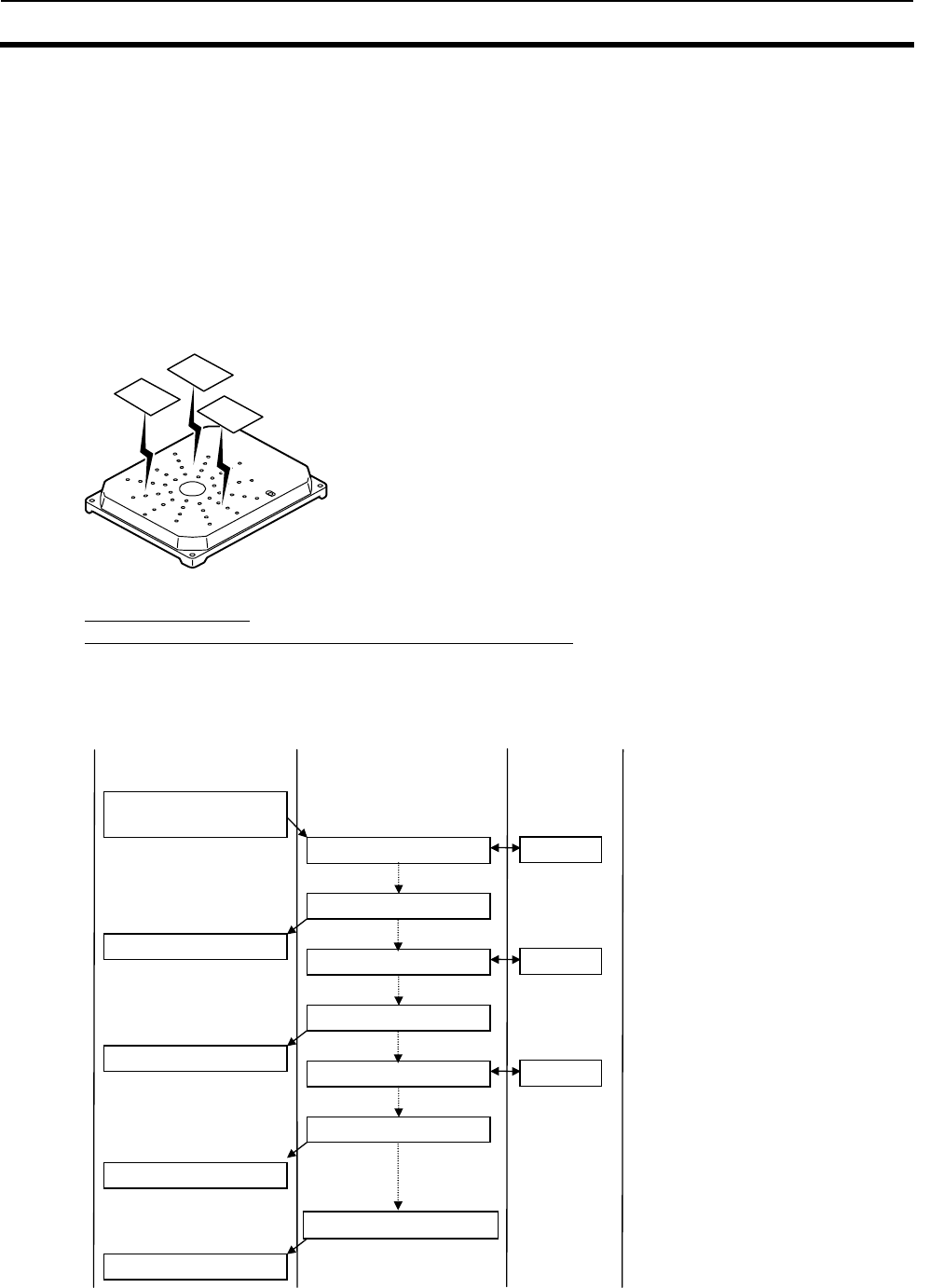
5-2 Control Procedures for Each Communication 5-2
5-11
5-2-3 Multiple Access
In Multiple Access, the Reader/Writer can communicate with all of the multiple Tags present
in the antenna communication area. In I.CODE1 Mode, the Tag code corresponding to the
number of Tags present in the communication area must be specified. For the Tag number
specifications, refer to SECTION 5-2-5.
When the Tag is on the boundary of the communication area or enters the communication area
more than once because of swing, the normal operation may be interrupted because the Tags
are processed more than once. In this case, it is recommended that UID/SNR addition setting
be enabled to evaluate the Tags on the host side. In addition, one processing per Tag is
available by enabling the Duplicate Communication Protecting Function. For Duplicate
Communication Protecting Function,, refer to SECTION 3-8.
5-2-3-1 Multiple Trigger Mode
Read Command (RD)
Write Command (WT) with UID/SNR addition setting enabled (Excluding I.CODE1 Mode).
At the reception of the command, the Reader/Writer communicates with all the Tags in the
communication area and returns communication results with each Tag, as responses. After
communicating with all the Tags, it returns Detection End Response (Response Code: 72). When no Tag is
present in the communication area, it returns to Detection End Response (Response Code: 72).
In I.CODE1 Mode, when the Reader/Writer could not communicate with all of the detected tags or when it
detected non-processable Tags during the processing sequence, it returns a warning code (Code: 0□) as
Response Code. (Refer to SECTION 5-3-7-2).
(タグ)(リーダライタ)
レスポンス受信
レスポンス受信
レスポンス受信
レスポンス受信
(上位機器)
タグ接近待ち
④タグがR/Wアンテナの交信領域内にあるとコント
ローラはタグと交信を行います。
①リーダライタがコマンドを受信します。
マルチリードコマンド
(UID 付加設定)
レスポンス(UID1)
タグ(UID1)
タグ検出
レスポンス(UID2)
タグ(UID2)
タグ検出
レスポンス(UID3)
タグ(UID3)
終了レスポンス72 ⑤信領域内の全てのタグとの交信が終了した時点
で、終了レスポンスを返します。
③ レスポンスに UID を付加してレスポンスを返します。
② リーダライタはタグとの交信処理を行います。
(Host) (Reader/Writer) (Tag)
Waits for a Ta
g
to a
pp
roach
Receives a res
p
onse
Receives a res
p
onse
Receives a res
p
onse
Receives a res
p
onse
Ta
g
(
UID1
)
Ta
g
(
UID2
)
Ta
g
(
UID3
)
Response (UID1)
Response (UID2)
Response (UID3)
Ta
g
Detection
Ta
g
Detection
Detection End Response 72. (5)After communicating with all the Tags
in the communication area, the
Reader/Writer returns Detection End
Response.
(3)Adds UID to the response and
returns the response.
(2)The Reader/Writer communicates
with the Tag.
(1)The Reader/Writer receives a
command.
(4)When a Tag is present in the
Reader/Writer antenna communication
area, the Reader/Writer communicates
with the Ta
g
.
Multi-Read Command
(UID addition setting)
5-2 Control Procedures for Each Communication 5-2
5-12
In Write Command (WT) with UID/SNR addition setting disabled (in I.CODE1 Mode, the command with
UID/SNR addition setting eabled is also covered),
the Reader/Writer communicates with all the Tags in the communication area on receiving the command,
and returns the results of the communications with each tag as a response. At the completion of
communicating with all the Tags, it returns Detection End Response (Response Code: 00) once.
The number of Tags with which the communication has been normally completed is added to Detection
End Response. When no Tag is present in the communication area, it returns Detection End Response
(Response Code: 72).
マルチ・トリガ・コマンド(WT)
(上位機器) (リーダライタ) (タグ)
交信処理 タグ(0)
交信処理 タグ(1)
全てのタグの書き込みが終了
レスポンス
In ISO Mode, if the communication with the detected Tag failed, the Reader/Writer returns an error
response immediately and moves on to process another Tag. At the completion of communicating with all
the detected Tags, it returns the Detection End Response and terminates the command processing.
In I.CODE1 Mode, the Response Code is set to 00 only after the communications with all the detected Tags
have been completed successfully. When the number of Tags detected exceeds the number specified by the
Tag code in command data, the Response Code is replaced with a warning code (Code: 0□), (Refer to
SECTION 5-3-7).
If data writing process in even one Tag has failed, the Reader/Writer returns to Write Process Error
(Response code: 71), and terminates the command processing.
Note:
In processing Multi-Trigger Command, some Tags may not be processed due to their conditions (including the
distances between the antenna and Tag, or those between the Tag and another Tag). The operating system must
be configured to check the number of processed Tags based on the number of returned responses or normally
processed Tags, and match them against the actual number of the Tags.
(Host) (Reader/Writer) (Tag)
Multi-Trigger Command (WT)
Communication process
Communication process
A
ll the Tags have been written
Response
Response
Tag(0)
Tag(1)
5-2 Control Procedures for Each Communication 5-2
5-13
5-2-3-2 Multiple Repeat Mode
Read Command (RD)
Write Command (WT) with UID/SNR addition setting enabled (Excluding I.CODE1 Mode).
The Reader/Writer continues to return a response every time it has communicated with a Tag in the
communication area. This operation continues until the Stop Command (ST) or Reset Command (XZ) has
been executed. Other commands are rejected in this state.
Write Command (WT) with UID/SNR addition setting disabled (In I.CODE1 Mode, the command with
UID/SNR addition setting enabled is also covered).
In this case, do not execute the commands in Multiple Repeat Mode. Basically, the operation in Multiple
Trigger Mode is performed repeatedly.
However, the operation may become highly complicated, depending on the Tag status.
(タグ)(リーダライタ)
レスポンス受信
レスポンス受信
レスポンス受信
(上位機器)
タグ接近待ち
④タグがR/Wアンテナの交信領域内にあるとコント
ローラはタグと交信を行います。
①リーダライタがコマンドを受信します。
マルチリードコマンド
(UID 付加設定)
レスポンス(UID1)
タグ(UID1)
タグ検出
レスポンス(UID2)
タグ(UID2)
タグ検出
レスポンス(UID3)
タグ(UID3)
⑤ストップコマンド(ST)でコマンド動作を停止するま
で、タグ検出を継続します。
③ レスポンスに UID を付加してレスポンスを返します。
② リーダライタはタグとの交信処理を行います。
タグ検出
(Host) (Reader/Writer) (Tag)
Multi-Read Command
(UID addition setting)
Waits for a Ta
g
to a
pp
roach
Receives a res
p
onse
Receives a res
p
onse
Receives a res
p
onse
Response (UID1)
Response (UID2)
Response (UID3)
Tag Detection
Tag Detection
Tag Detection
Ta
g
(
UID3
)
Ta
g
(
UID2
)
Tag (UID1)
(1)The Reader/Writer receives a
command.
(2)The Reader/Writer communicates
with the Tag.
(3)Adds UID to the response and
returns the response.
(4)The Reader/Writer communicates with
a Tag when the Tag is in the Reader/Writer
antenna communication area.
5. The Reader/Writer keeps on detecting
the Tags until the command has been
terminated by Stop Command (ST).
5-2 Control Procedures for Each Communication 5-2
5-14
5-2-4 Selective Access
Selective Access is a function to communicate with the specified Tags among multiple Tags in
the antenna communication area. The processes vary depending on the Reader/Writer’s mode.
5-2-4-1 ISO Mode
First, the Reader/Writer reads out the UID of the Tag in the communication area using Read
Command (in multiple processing modes). The UID is readable when UID/SNR addition
setting option is enabled in advance using the respective command (SN). When the UID is
already identified, the execution of Read Command can be skipped. Then, the Reader/Writer
communicates with the specified Tag based on the obtained UID.
(1) The Reader/Writer reads the UID of the Tag using Read Command.
It reads out UID data of the Tag by executing a Multiple Trigger Mode command with its
UID/SNR addition setting enabled.
12
3
(2) The Reader/Writer communicates with the specified Tag (No. 2 in the figure below) by
specifying the UID obtained in 1 using UID Select Read/Write command.
The ReaderWriter communicates with the Tag specified by the UID. For UID Select
Command, specify SL for the communication, and specify the UID of the communication
target Tag in the UID area in hex number, 123.
12
3
Note:
Some Tags detected by UID read (Tag detection) may not be communicated with Selective Access mode using UID
Select (Tag designation) command, depending on the Tag conditions (the distances between the antenna and tag,
or those between the Tag and another Tag). This is especially true when the Tag exists in the boundary area of
the communication area. The operating system must be configured to check the number of detected Tags against
the number of Tags the Reader/Writer communicated with (or the number of the actual Tags).
5-2 Control Procedures for Each Communication 5-2
5-15
■Selective Access Operation: In ISO Mode
■Exceptions
(1) When the Tag with the UID specified by UID Select Command does not exist in the communication area,
the Reader/Writer returns No Tag error (Response Code:72) to the host.
(Tag) (Reader/Writer)
Receives a response
Receives a response
Receives a response
Receives a response
Receives a response
(Host)
Waits for a Tag
(7) The controller performs the
communication processing with the
(6) Controller receives UID Additional
Command of the Tag to communicate
with.
(4) When a Tag is in the communications
area of the Reader/Writer Antenna, the
Reader/Writer communicates with the
(1) The Reader/Write receives a command.
Multi-Read Command
(UID Additional Setting)
A response (UID1)
Tag (UID1)
Tag detection
A response (UID2)
Tag (UID2)
Tag detection
A response (UID3)
Tag (UID3)
End Response “72”
Communications process
Specifies Tag (UID2)
Response of the Tag (UID2)
Tag (UDI2)
(5) Returns an end response when the
controller completes to communicate
with all Tags in the communications area.
(3) The Reader/Writer returns a response with
UID.
(2) The Reader/Writer communicates with the
Tag.
The Reader/Writer communicates with the
Tag when it is in the Reader/Writer antenna
communication area.
After the Reader/Writer has communicated
with all the Tags in the communication area,
it returns the Detection End Response.
The Reader/Writer receives UID Select
Command with the UID of the
communication target Tag added.
The communication with the Tag with the
specified UID is processed.
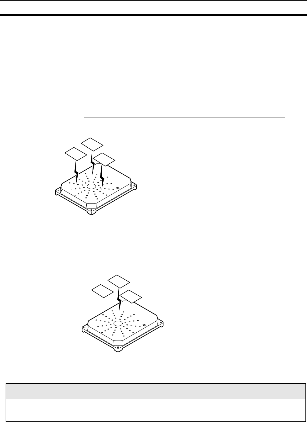
5-2 Control Procedures for Each Communication 5-2
5-16
5-2-4-2 I.CODE1Moed
After allocating the Temporary numbers to the Tags in the communication area using Tag
Detection Command, the Reader/Writer communicates with the Tags based on the allocated
numbers. The Tag code must be specified as command data according to the numbers of the
Tags present in the communication area. For Tag number specifications, refer to SECTION 5-
2-5.
1. Numbers are allocated to the Tags by Tag Detection Command.
Tag Detection Command, the state enters the Select State, where the mapping of the
Tags in the antenna communication area and their Temporary numbers are stored. In
Select State, all the commands are rejected except the Tag Designation Command. The
Select State is valid until Stop Command (ST) has been executed.
12
3
2. After allocating the numbers to the Tags, the Reader/Writer communicates with the
specified Tag (No.2 in the figure below) using Tag Designation Command.
The ReaderWriter communicates with the Tag specified by the Temporary number. It can
communicate with the Tags repeatedly in the Select State.
12
3
Tag Detection Command/Tag Designation Command
For Tag Detection Command, specify LT as the communication method of the command. For Tag Designation
Command, specify 00 to 7F as the communication method of the command. (To specify the Tag with Temporary
number 1, specify 01).
5-2 Control Procedures for Each Communication 5-2
5-17
■Selective Access Operation: In I.CODE1 Mode
■Exception(In I.CODE1 Mode)
1) When the Tags with the temporary numbers selected by the Tag Selection Command are not present,
the Reader/Writer returns a communications error (Response Code:72) to the host.
2) When the Tag Selection Command selects temporary numbers other than those stored by the
Reader/Writer by the Tag Detection Command, the Reader/Writer returns a format error (Response
Code:14) to the host.
3) The Reader/Writer cannot communicate with the tag which a Temporary number is assigned by the host,
once the Tag goes out of communication area while the Reader/Writer selecting the tag to be read,
even if the Tag exists in the communication area, Then the Reader/Writer sends back to "No Tag error
command (Response Code72)"to the host.
Tag Detection Command (RD)
(Host) (Reader/Writer) (Tag)
Communications process Tag (0)
Holds a response
Receives a response
Receives a response
Receives a response
Communications process Tag (1)
Detection End Response “72”
Specifies a Tag (2)
Communications process Tag (2)
Response from Tag (2)
Stop command
R
emoves
th
e s
t
ore
d
t
emporary
numbers
Holds a response
A response which is held
Returns (with Temporary No.)
Receives a response
(1) Reader/Writer receives a command
(2) The Reader/Writer communicates with the Tag;
it Adds a temporary number to the response and
stores it within the Reader/Writer.
(3) On completion of communications with all of the Tags
existing in the R/W communications area.
It Returns in sequence the responses containing
temporary numbers
(4) On completion of responding to all of the Tags, it
returns the Detection End Response (72).
(5) The Reader/Writer
receives a Tag Selection
Command containing the
temporary number
corres
p
ondin
g
to the Ta
g
(6) The Reader/Writer
communications with the
Ta
g
with the s
p
ecified
(7) On receiving the Stop Command, the
Reader/Writer removes the stored temporary
numbers.
5-3 Command-Response Format 5-3
5-18
5-2-5 Specifying a Tag Code: I.CODE1 Mode
The timeslot setting is the setting in the command frame when communicating with multiple Tags
simultaneously using Multi-system commands. This setting must be set according to the number of Tags
with which to communicate simultaneously. Refer to the table below for the relationship between the
number of Tags and this setting.
Specifying a Tag
Code
Max. No. of Tags with which simultaneous
communication is possible
1 ∼2
2 ∼4
3 ∼8
4 ∼16
5 ∼32
6 ∼64
7 ∼128
Example: If the number of Tags is seven, select Tag Number setting 3.
Note:
● For the Multi Trigger(MT) and the Multi Read(MR), if more Tags than have been set using the timeslot setting
enter the communications range, a "70" error (warning) may occur. (e.g., When the timeslot setting is "2" and
there are five Tags in the communications area.)
●For the Special Read (refer to 5-2-1-6) command, the anti-collision process is not performed. Therefore, read
data will be returned even If there are more Tags than the timeslot setting in the communications area.If a
collision occurs, such data will not be returned.
● The higher the timeslot setting is, the longer the communications time is required. Consequently, setting a
higher timeslot setting than required for the number of Tags in use unnecessarily lengthens communications
time, so select a suitable setting.
5-3 Command-Response Format 5-3
5-19
5-3-1 Command Frame Structure
The Reader/Writer continuously receives signals from STX through ETX, and executes the command
when the correct node number is received (*1). If, after receiving an STX signal, another STX signal is
received before an ETX signal is received, the second STX signal is given command priority.
Node No. Command Code Option BCC
STX "" "" ETX
1 2 2 1 1
Name Description
STX Indicates the beginning of a communication frame (text). Expressed by
ASCII code 02h.
Node No. Indicates the Reader/Writer to communicate with by its node No. This
number can be set within the range between 00 and 31 decimal.(*1)
Command Code
Indicates the command that the Reader/Writer executes. For the
command codes that are available, refer to Command Code List in 5-3-
3.
Option Makes specified optional settings or specifies read/write data. For
details, refer to the format of the appropriate command.
ETX Indicates the end of a communication frame (text) Expressed by ASCII
code 03h.
BCC
Stands for Block Check Character (hereinafter referred to as "BCC").
The result of the horizontal parity calculation from immediately after
STX through ETX is expressed using one character. You can enable or
disable the BCC command using the communications port setting
command.For BCC calculation method, refer to 5-3-8 Example BCC
Calculation.
:COM2 is a port for setup and can communicate without depending on a node No.
5-3-2 Response Frame Structure
Node No. Retry Flag Command Code Response code Text data BCC
STX "" "" "" "" ETX
1 2 1 2 2 1 1
Name Description
Node No. Indicates the node No. that has been assigned to the Reader/Writer.
Retry Flag
This flag will be set to "0" when ACK/NACK control has been disabled.
In ACK/NACK control, a response will be re-transmitted with the
retry flag set to "1" if, after returning a response, ACK has not been
received within a pre-determined period of time or if NACK has been
received.
Command code Indicates the code of the command that the Reader/Writer executed.
Response Code Indicates the result of command execution.
Refer to 5-3-7 Response Code List for different response codes.
Text data Sent in response to specific commands. For the content, refer to the
frame structure of each command.
:The contents of STX, ETX, and BCC are the same as those in command frames.

5-3 Command-Response Format 5-3
5-20
5-3-3 Command Code List
The command type is set by specifying the following command types as a command code: There are four
major types of commands.
(1) Communications command
This command communicates with a Tag.
(2) System command
This command accesses to the system area of a Tag.
(3) Reader/Writer control command
This command controls the Reader/Writer, e.g. stopping a command in process, and/or resetting.
(4) Setting command
This command sets the system of the Reader/Writer.
Command
type
Comma
nd code Command name Description Remarks
RD Read Reads data from the Tag memory. This is also used
for some system areas.
WT Write Writes data to the Tag memory. This is also used for
some system areas.
PR Polling Read Executes a Single Auto Read through Polling processing.
PW Polling Write Executes a Single Auto Write through Polling processing.
PC Polling Check Inquires the Reader/Writer under Polling processing.
PE Polling Cancel Cancels Polling processing.
MC Memory Check Compares check codes in Tag memory. I.CODE1 Mode
Only
Communi
cations
Command
MK Memory Calculation
Calculates check codes in Tag memory. I.CODE1 Mode
Only
SR System Read Reads system information of a Tag. ISO Mode Only
SW System Write Sets AFI, DSFID and EAS of a Tag. ISO Mode Only
SL System Lock Locks AFI, DSFID and EAS of a Tag. ISO Mode Only
ES EAS Setting Enables or disables the EAS command. I.CODE1 Mode
Only
QB QuietBit Setting Sets QuietBit I.CODE1 Mode
Only
LK Lock Locks the Tag memory by page.
LR Lock Setting Read Reads lock setting data of the Tag. ISO Mode only. ISO Mode Only
System
Command
EA EAS Check Checks EAS.
ST Stop Stops the communications with a Tag.
XZ Reset Resets the Reader/Writer after receiving a command.
AK ACK
In a case where the system under ACK/NACK control
cannot receive a response properly, send this command to
the Reader/Writer.
NK NACK
In a case where the system under ACK/NACK control
cannot receive a response properly, send this command to
the Reader/Writer.
CC I/O Control Changes and reads user input and output.
TS Test Sends the data received from the host back to the host.
Reader/
Writer
Control
Command
VS Version Reads the software version of the Reader/Writer.
AE AFI Enable/diable
Changeover
Sets whether AFI is used or not when communicating with a
Tag. ISO Mode Only
AF AFI Reading Sets AFI in the Reader/Writer. ISO Mode Only
FC Family Code Setting Sets a Family Code in the Reader/Writer. I.CODE1 Mode
Only
AI Application ID
Setting
Sets an Application ID in the Reader/Writer. I.CODE1 Mode
Only
SN UID (SNR)
Additional Setting
Sets whethr or not UID (SNR) will be added to a read
response.
NN Node No. Sets the node number in the Reader/Writer.
CP Communications
Port Setting
Sets the baud rate, data length, parity bit, stop bit,
ACAK/NAK control, timeout period, BCC addition, etc, in
the Reader/Writer.
CT Communications
Type Setting
Sets the communications type in the Reader/Writer.
Setting
Command
CM
Tag
Communications
Mode
Set the Tag communications mode in the Reader/Writer.

5-3 Command-Response Format 5-3
5-21
AC Antenna
Changeover
Sets the antenna changeover in the Reader/Writer.
TM Terminal Resistance Sets the terminal resistance for RS485 in the Reader/Writer.
FL Offline Mode Setting Sets which mode the Reader/Writer will start online or
offline.
IS Initialization of
Setting
Reset the Reader/Writer to the factory settings.
EW Set Value Writing Stores the Reader/Writer set value on the EEPROM
TY Chip Operating Mode
Switch
Switches I.CODE1/I.CODE SLI modes
MX
Duplicate
Communication
Protecting Setting
Enables/Disables Duplicate Communication
Protecting Function sets the number of the tables.
CA I/O Automatic
Changeover setting
Enables/Disables I/O Automatic Changeover setting.
* In Offline Mode, the only commands accepted are Stop Command (ST) or Reset Command(XZ).
5-3-4 Communication Method List
The communication mode is set by specifying the following communication code as the
command-data option. The available communication modes vary, depending on the commands
or operation modes.
Name Code Description
Single Trigger ST Immediately after receiving a command, the Reader/Writer
communicates with a Tag and returns a response.
If the Tag is missing, an error (Code:72) is returned.
During communications, only one Tag should exist in the
communications area.
Single Auto SA After receiving a command, the Reader/Writer waits for a Tag to
enter the communications area. Next, the Reader/Writer
communicates with the entering Tag and returns a response. During
communications, only one Tag exists in the communications area.
Single Repeat
(ISO mode)
SR After receiving a command, the Reader/Writer waits for a Tag to
enter the communications area. Next, the Reader/Writer
communicates with the entering Tag and returns a response. After
sending the response, the Reader/Writer enters a Tag waiting state
again and repeats this process until receiving the Stop(ST) or Reset
Command(XZ).
During communications, only one Tag should exist in the
communications area.
This method is for ISO mode only. Do not specify this method in
I.CODE1 mode.
Multi-trigger MT Immediately after receiving a command, the Reader/Writer
communicates with all of the Tags existing in the communications
area and returns responses corresponding to each Tag.
If the Tag is missing, an error (Code:72) is returned.
Multi-repeat MR The Reader/Writer waits for Tags to enter the communications area.
It communicates with all of the Tags existing in the communications
area and returns responses corresponding to each Tag. After
completing communications, the Reader/Writer disables the operation
of the Tag. After sending the response, the Reader/Writer enters a
Tag waiting state again and repeats this process until receiving the
Stop(ST) or Reset Command(XZ).
FIFO Trigger FT Immediately after receiving a command, the Reader/Writer
communicates with a Tag and returns a response.
After completing communications, the Reader/Writer disables the
operation of the Tag. After sending the response, the Reader/Writer
will continue to operate until it receives a FIFO command, Stop(ST)
command, or Reset command(XZ).
During communications, only one Tag in the Communications area is
operable.
FIFO Auto FA After receiving a command, the Reader/Writer waits for a Tag to
enter the communications area. Next, the Reader/Writer

5-3 Command-Response Format 5-3
5-22
communicates with the entering Tag and returns a response. After
sending the response, the Reader/Writer will continue to operate until
it receives a FIFO command, Stop command (ST), or Reset
command(XZ).
After sending the response, the Reader/Writer enters a command
waiting state. During communications, only one Tag in the
Communications area is operable.
FIFO Repeat FR The Reader/Writer waits for a Tag to enter the communications area
and communicates with the entering Tag. After completing
communications, the Reader/Writer disables the operation of the Tag.
After sending the response, the Reader/Writer enters a Tag waiting
state again and repeats this process until receiving the Stop (ST) or
Reset Command(XZ). During communications, only one Tag in the
Communications area is operable.
UID Select
(ISO Mode)
SL Communicates with the Tags specified by UID among the Tags in the
SL communication area. If the specified Tag does not exits, the No
Tag Error (Code: 72) is returned.
Tag Detection, Tag
Designation
(I.CODE1 Mode)
LT, Communicates with multiple Tags in the communication area
specified by the allocation of the Temporary number (Tag Detection)
and by the Temporary number (Tag Designation). Selective access is
performed by specifying the two communication settings as a unit.
Fast Read Access
(I.CODE1 mode)
UT, UA,
UR
Fast data reading performed by the I.CODE1-specific sequence. Both
Single and Multi Accesses are available by setting the corresponding
Tag codes.

5-3 Command-Response Format 5-3
5-23
5-3-5 Command-by-Command Communication Method List
The communication modes specifiable as a communications method vary, depending on the
command. Communications method options are not provided for some commands, their
communication methods are determined by specifying the command types.
Single FIFO Multiple Selective
Communica-
tions
Method
Command
Tri-
gger Auto Repeat Tri-
gger Auto Repeat Tri-
gger Repeat
Tag
Detec
tion
Tag
Selection
Fast
Read
(I.CO
DE1
mode)
Read 9 9 9 9 9 9 9 9 9 9 9
Note 9 9 − 9 9 9 9 9 − 9 −
Polling Read *1 − (9) − − − − − − − − −
Polling Write *1 − (9) − − − − − − − − −
Memory Check *2 (9)− − − − − − − − − −
Memory Calculation
*2 (9)− − − − − − − − − −
System Read*2 (9)− − − − − − − − − −
System Write 9 − − − − − − − − 9*3 −
System Lock 9 − − − − − − − − 9*3 −
EAS Setting*2 (9)− − − − − − − − − −
QuitBit Setting*2 (9)− − − − − − − − − −
Lock Setting*2 (9)− − − − − − − − − −
Lock Setting Read*
2 (9)− − − − − − − − − −
EAS Check *4 − − − − − − − (9) − − −
9 : :Able to select communications method
− : :Not able to select communications method
*1 The communication is fixed to Single Auto. The communication method cannot be specified by users.
*2 The communication is fixed to Single Trigger. The communication method cannot be specified by users.
*3 Specifies the communication method by system designation in command data. Selective/UID Select can
be specified for EAS only. Settings for other system data is fixed to Single Trigger.
*4 The communication is fixed to Multiple Repeat. The communication method cannot be specified by
users.
5-3 Command-Response Format 5-3
5-24
5-3-6 Specifying a Data Code
In the Command code area of the command data, whether the Reader/Writer reads or writes data as
ASCII code (or JIS8 code) or HEX code numeric data is specified.
Name Code Description
ASCII Code A A character of data occupies 1 byte (1 address) on a Tag as an
ASCII code or a JIS 8 code.
Control codes 02 (STX) and 03 (ETX) cannot be used.
HEX code H A character is handled as hexadecimal data. Therefore, only
characters from 0 to F are accepted. Two characters of data
occupy 1 byte (1 address) on a Tag.
• Example of ASCII Representation
When writing "V720" to four bytes of memory of page 00 using ASCII data, the data will occupy the
Tag's memory as follows:
byte 0 byte 1 byte 2 byte 3
page 00h 5 6 3 7 3 2 3 0
V 7 2 0
• Example of Hexadecimal Representation
When writing "12345678" to four bytes of memory of page 01h using hexadecimal data, the data will
occupy the Tag's memory as follows:
byte 0 byte 1 byte 2 byte 3
page 00h 1 2 3 4 5 6 7 8

5-3 Command-Response Format 5-3
5-25
5-3-7 Response Code List
5-3-7-1 ISO Mode
Type Response
Code Name Description
“00” Normal completion The received command ends normally with no error.
“72” Multi-processing end Communications end response when a multi-trigger function is used.
“74” Polling command
received ・Polling command has been received normally.
・Polling Check is received before the completion of communications with a Tag.
“75” Polling processing
canceled
Polling processing is canceled before the completion of communications with a
Tag.
Normal
completion
“76” Polling processing
canceled
Polling processing is canceled after the start of communications with a Tag.
“10” Parity error A parity error occurs in one of the characters of the received command.
“11” Framing error A framing error occurs in one of the characters of the received command.
“12” Overrun error An overrun error occurs in one of the characters of the received command.
“13” BCC error The received command has an incorrect BCC.
“14” Format error ・The command format is incorrect.
・A stop command is received in command-waiting status.
・An I.CODE1-mode specific command/function is executed.
Host
communica
tions error
“18” Frame length error ・ETX is not received in 289 characters or less after STX is received.
“70” Communications
error ・An error occurs during the communications with a Tag, and communications
cannot end normally.
“71” Write process error ・Failed to write correct data onto a Tag. (Verification error)
・An error occurred in the data writing process between a Tag,
preventing the process from being completed normally.
“72” No Tag error ・No Tag is present in front of Antenna when a Trigger command is executed.
・There are multiple Tags within the communications area when using Single
Access mode.
“79” Command error ・ Refer to the correlation table of ISO/IEC Error Codes.
“7A” Address error ・Unavailable pages. (ISO/IEC standard error code 10)
*Results in 79 error on I.CODE SLIs because the Tag is not supported.
Communica
tions error
“7E” Lock error [ver1.20
and higher]
・Writing onto a locked page. (ISO/IEC standard error code 12) *Results
in 79 error on I.CODE SLIs because the Tag is not supported.
“7C” Communication
circuit error
・An error occurred in the Reader/Writer communication circuit.
System
error
“93” Memory error ・The EEPROM for the operating condition setting cannot be re-written
normally.
■ Correlation table of ISO/IEC Error Codes
When a Tag incorporating ISO/IEC chip (including I.CODE SLI chip) returns an error response, the
Reader/Writer responses a Response Code shown in the table below.
ISO code Description Response code of module
01 An unadopted command. No request command can be
recognized. 79
02 An unrecognizable command. ex. format error. 79
03 An unadopted arbitrary command 79
0F An unaccountable error or unadopted error code. 79
10 A specific block cannot be use. (There is none) 7A
11 A specific block cannot be relocked since the block has
been already locked. 00
12 A specific block cannot be rewritten since it is locked. 71/7E
13 A specific block has not completed writing correctly. 71
14 A specific block has not completed locking correctly. 71
Others RFU 79

5-3 Command-Response Format 5-3
5-26
5-3-7-2 I.CODE1 Mode
Type Response
Code Name Description
“00” Normal completion The received command ends normally with no error.
Multi-processing end Communications end response when a multi-trigger function is used.
“72”
Selective detection completion Communications end response when a selective access/detection
function is used.
“74” Polling command received ・Polling command has been received normally.
・Polling Check is received before the completion of communications
with a Tag.
Polling processing canceled Polling processing is canceled before the completion of
communications with a Tag.
“75”
Data normal Results of the memory calculation command (MK) check code
verification are normal.
Polling processing canceled Polling processing is canceled after the start of communications with
a Tag.
Normal
completion
“76”
Data error Results of the memory calculation command (MK) check code
verification show an error.
“10” Parity error A parity error occurs in one of the characters of the received
command.
“11” Framing error A framing error occurs in one of the characters of the received
command.
“12” Overrun error An overrun error occurs in one of the characters of the received
command.
“13” BCC error The received command has an incorrect BCC.
“14” Format error ・The command format is incorrect.
・A stop command is received in command-waiting status.
In Selective Access mode;
1) A temporary number not saved using the Tag detection
command is specified.
2) A tag detection command normal end is retried after it has
been sent.
・The specified, Temporary number is not saved by Tag
Detection Command.
・An ISO-mode specific command/function is executed.
Host
communications
error
“18” Frame length error ・ETX is not received in 289 characters or less after STX is received.
“70” Communications error ・An error occurs during the communications with a Tag, and
communications cannot end normally.
“71” Write process error ・Tag is in an area that can be read, but not written to.
・You are trying to write to a locked page (i.e., write-protected).
・The correct data cannot be written to the Tag.
・Verify read results in an error.
Communication
s error
“72” No Tag error ・No Tag is present in front of Antenna when a Trigger command is
executed.
・There are multiple Tags within the communications area when
using Single Access mode.
“7C” Communication circuit error ・An error occurred in the Reader/Writer communication
circuit.
System error
“93” Memory error ・The EEPROM for the operating condition setting cannot be
re-written normally.
“01” Specified No. of Tags exceeded ・More Tags than have been specified in the Tag No. setting have
entered the communications area.
“02” Specified No. of retries exceeded ・Tag detection has been retried the specified number of times to
find all the Tags in the communications area, but some Tags have
not been detected.
“03” No. of Tags exceeded
No. of retries exceeded
・Two of the warning, “01” and “02,” have occurred.
“04” Communications error ・An error occurs during communicating with Tags, resulting in
successful communications with only some of the Tags.
“05” Specified No. of Tags exceeded
Communications error ・Two of the warnings, “01” and “04,” have occurred.
“06” No. of Tags exceeded
Communications error ・Two of the warnings, “02” and “04,” have occurred.
Warning
“07” No. of Tags exceeded
No. of retries exceeded
Communications error
・All the three warnings, “01,” “02,” and “04,” have occurred.
:The warning code is issued for Multiple Trigger(MT) and Multiple Repeat(MR) Modes only.

5-3 Command-Response Format 5-3
5-27
5-3-8 Example BCC Calculation
BCC is the result of the horizontal parity calculation of the data right after STX up to ETX inclusive.
Refer to JIS5001 Transmission Path Character Configuration and Using Horizontal Parity for details.
Node No.
Command
code Text
BCC
STX 0 0 R D S T A 0 0 0 0 1 ETX 62
Command
data
ASCII code data
0 0011 0000
EOR
0 0011 0000
EOR
R 0101 0010
EOR
D 0100 0100
EOR
S 0101 0011
EOR
T 0101 0100
EOR
A 0100 0001
EOR
0 0011 0000
EOR
0 0011 0000
EOR
0 0011 0000
EOR
0 0011 0000
EOR
1 0011 0001
EOR
ETX 0000 0011
Calculation
results
0110 0010
Precautions on the communication-control software programming:
The BCC is a character representing the result of the horizontal parity check performed for data and ETX. The
BCC could be any code from 00h to FFh. (From 00h to 7Fh for 7-bit data). The communication control program
that runs on the host must be designed assuming the case where BCC is not defined as STX/ETX control
character or other characters.
* Some characters may not be available, depending on the program development environment or coding
method. Check the restrictions of the development environment of your choice.

5-4 Communication Commands 5-4
5-28
5-4-1 Read (RD)
This command reads data from a Tag in the communications area.This is also used to read
some system areas in I.CODE1.
<Command Format>
STX
Node No..
Command
Code
“RD”
Communic
ations
method
Data
type
Tag
type
First read
page
No. of
read pages
ETX BCC
1 2 2 2 1 1 2 2 1 1
Communications
method
Specifies a communications method
ST: Single Trigger FA: FIFO Auto
SA: Single Auto FR: FIFO Repeat
SR: Single Repeat MT: Multi Trigger
FT: FIFO Trigger MR: Multi Repeat
*Refer to SECTION 5-3-4 Communication Mode List for details.
Data type Specifies whether the read data is represented in ASCII or HEX.
A : ASCII code
H : HEX code
*Refer to SECTION 5-3-6 Specifying a Data Code for details.
In ISO mode Specifies the Tag type.
A: I.CODE SLI chip
Tag
typ
e
* In I.CODE1
mode (Tag No.
setting)
Set the number of Tags which communicate simultaneously.
0 : when executing single or FIFO communications
“1 to 7” : when executing multi-communications
*Refer to SECTION 5-2-5 Specifying a Tag Code for details.
First read page Specifies the first page in hexadecimal to read from the Tags.
Specification range: 00 to FFh (in ISO mode: 00 to 1Bh for I.CODE
SLI chip)
Specification range: FB to 0Ah (in I.CODE1 mode)
*Refer to SECTION 2-4 Memory Map of Tag for details.
No. of read pages Specifies the number of pages in hexadecimal to read from the Tags.
Specification range: 01 to FFh (in ISO mode: 01 to 1Ch for I.CODE
SLI)
Specification range: 01 to 10h (in I.CODE1 mode)
*The setting number of each Tag type is valid only when it is within the range of each
operating mode in Reader/Writer.
<Response Format>
(1) Read data: there are responses according to the number of Tags in its communications
area when multi- communications method is executed.
STX Node No.
Retry
Flag
Command
Code
“RD”
Response
Code
“00”
UID(SNR) Read data ETX BCC
1 2 1 2 2 16 As specified 1 1
(2) Completion of communications (Multi/Trigger only): When the communications with
all tags in communications area is completed.
STX Node No
Retry
Flag
Command
Code
“RD”
Response
Code
“72”
ETX BCC
1 2 1 2 2 1 1
Response code 00: Normal completion
For other Response Codes, refer to SECTION 5-3-7 Response Code List.
UID (SNR) Indicates UID (SNR) having been read from a Tag.
When UID (SNR) (Tag-specific code) additional setting is valid, read
data will be preceded by UID. UID(SNR)
Read Data Indicates the data having been read from a Tag. The number of
characters of data is as follows.
ASCII code: No. of read pages x 4
HEX code: No. of read pages x 8

5-4 Communication Commands 5-4
5-29
5-4-2 Write (WT)
Writes data to the Tag in the communication area. Also used to write data to some system
areas in I.CODE1.
There is no need to perform the verify read process, since this command performs it as part of
its execution.
<Command Format>
STX
Node No.
Command code
“WT”
Communi
cations
method
Data
type
Tag
type
First write
page
No. of
write
pages
Write
data
ETX BCC
1 2 2 2 1 1 2 2 As specified 1 1
Communications
method
Specifies the communications method with a Tag.
ST: Single Trigger FR: FIFO Repeat
SA: Single Auto MT: Multi Trigger
FT: FIFO Trigger MR: Multi Repeat
FA: FIFO Auto
*Refer to SECTION 5-3-4 Communication Mode List for details.
Data type Specifies whether the read data is represented in ASCII or HEX.
A: ASCII code
H: HEX code
**Refer to SECTION 5-3-6 Specifying a Data Code for details.
In ISO mode Specifies the Tag type.
A: I.CODE SLI chip
Tag
typ
e
* In I.CODE1
mode
(Tag No.
setting)
Set the value with accordance with the number of Tags
communicating simultaneously.
0 : when performing Single or FIFO communications method
“1 to 7” : when performing multi communications method
*Refer to SECTION 5-2-5 Specifying a Tag Code for details.
First write page Specifies the first page in hexadecimal to write to the Tags.
Specification range: 00 to FFh (in ISO mode: 00 to 1Bh for I.CODE
SLI chip)
Specification range: FD to 0Ah (in I.CODE1 mode: the range of the
writable user area is FF page to 0A page)
*Refer to SECTION 2-4 Memory Map of Tag for details.
No. of write pages Specifies the number of pages to which data is written to Tags in
hexadecimal.
Specification range: 01 to FFh (in ISO mode: 01 to 1Ch for I.CODE
SLI)
Specification range: 01 to 0Eh (in I.CODE1 mode)
Write data Indicates data to be written to the Tag. The number of characters of
the data is as follows.
ASCII Code: No. of write pages x 4
HEX code: No. of write pages x 8
* Setting values of each Tag type is valid in the operating mode setting range in
Reader/Writer.
I.CODE1 System Area
From Page FD to Page FF is a system area for write-protect and QUIET/EAS settings. Depending on the
content of write data, a Tag may become write-protected or inaccessible, so be sure to understand these
pages fully before use.
It is strongly recommended that data be re-written using a command dedicated to system area re-writing
rather than Write Command (Refer to SECTION 5-5). Re-writing data when the Tag is in an unstable
communication area may destroy data in the system area, interrupting the communication with the Tag.
Be sure to re-write data while the Tag is in a stable communication area.
5-4 Communication Commands 5-4
5-30
<Response Format>
(1)In ISO mode
1) The completion of write (In a case where UID (SNR) additional setting is invalid)
STX Node No.
Retry
flag
Command
code
“WT”
Response
code
“00”
No. of
written
pages
ETX BCC
1 2 1 2 2 2 1 1
As specified
2)The completion of write (In a case where UID (SNR) additional setting is valid)
There are responses according to the number of Tags in communications area when multi-
communications method is preferred.
STX Node No.
Retry
flag
Command
code
“WT”
Response
code
“00”
UID(SNR) ETX BCC
1 2 1 2 2 16 1 1
3)The completion of communications (In a case where multi-trigger and UID (SNR) additional
setting is invalid.)
STX Node No.
Retry
flag
Command
code
“WT”
Response
code
“72”
ETX BCC
1 2 1 2 2 1 1
(2)In I.CODE1 mode
1)The completion of write
STX Node No.
Retry
flag
Command
code
“WT”
Response
code
“00”
Write
data
ETX BCC
1 2 1 2 2 2 1 1
Response code 00: Normal completion
For other Response Codes, refer to SECTION 5-3-7 Response Code List.
No. of write pages Returns the number of pages which data is written normally.
Does not return a response except that it completes normally.
Does not add during Single and FIFO communications.
UID(SNR) Indicates UID (SNR) having read from written Tags.
UID (SNR) (Tag-specified code) additional setting is added when it is
valid.
5-4 Communication Commands 5-4
5-31
5-4-3 Read (RD)-Tag Detection: I.CODE1 Mode only
This command assigns temporary Tag numbers to each of multiple Tags that are present in the
communications area. This command is available only when the system is in I.CODE1 mode.
In ISO mode, you must enable UID (SNR) additional setting, execute 5-3-1 Read Command
(RD), and get UID since the system uses UID (SNR) data as a temporary number.
<Command Format>
STX
Node No.
Command
code
“RD”
Communi
cations
method
Data
type
Tag
number
setting
First
read
page
No. of read
page
ETX BCC
1 2 2 2 1 1 2 2 1 1
Communications
method
Specifies a communications method with a Tag.
LT: Tag Detection
* For details, refer to 5-3-4Communications Methods.
Data type Specifies whether the read data is represented in ASCII or HEX.
A : ASCII code
H : HEX code
* For details, refer to 5-3-6 Data Type
Tag No. setting Set the value with accordance with the number of Tags communicating
simultaneously.
Specification range:1 to 7
* For details refer to 5-2-5 Tag No. setting.
First read page Specifies the first page in hexadecimal to read from the Tags.
Specification range: FB to 0Ah (when Block 4 for a Philips product is
used as the user memory,, refer to 2-4 of Section 2 Memory Map of Tag)
No. of read pages Specifies the number of pages from which data is read in hexadecimal.
Specification range: 01 to 10h
<Response Format>
(1) There will be as many responses as the number of Tags that are present in the communications area.
STX Node No.
Retry
flag
Command code
“RD” Response
code
“00”
Temporar
y No.
Read data ETX BCC
1 2 1 2 2 2 As specified 1 1
(2) Tag detection end response
STX Node No.
Retry
flag
Command
code
“RD”
Response
code
“72”
ETX BCC
1 2 1 2 2 1 1
Response code 01: Normal completion
72: The completion of Tag detection
For other response codes, refer to 5-3-7 Response code List.
Read data Indicates the data having been read from a Tag. The number of characters of the
data is as fellows.
ASCII code : No. of read pages x 4
HEX code : No. of read pages x 8
UID (SNR) Indicates UID (SNR) having been read from a Tag.
When UID (SNR) (Tag-specific code) additional setting is valid, read data will be
preceded by UID. UID(SNR)
Temporary No. The Temporary Number 00 to 7F are returned under normal conditions.
:This command works in I.CODE1 mode only. ISO mode is not available.
5-4 Communication Commands 5-4
5-32
5-4-4 Read (RD)-UID Select/Specified Tag
In ISO mode, this command reads data from the Tag in communications area by specifying UID (SNR).
In I.CODE1 mode, this command reads data from the Tag which is specified by the Temporary
Number.
<Command Format>
STX
Node No.
Command code
“RD”
Communic
ations
method
Data
type
Tag
type
First read
page
No. of read
pages
ETX BCCUID(SNR)
1 2 2 2 1 1 2 2 16 1 1
In ISO
mode
Specifies the communications method with a Tag.
SL: UID (SNR) select
* For details, refer to 5-3-4 Communications Methods
Commun
ications
method
In I.CODE
mode
Specifies the temporary No. in hexadecimal to read from the Tags.
□□: Temporary No. (The value of □□ should be within the range of
00h to 7Fh)
* For details, refer to 5-3-4 Communications Methods.
Data type Specifies whether the read data is represented in ASCII or HEX.
A: ASCII code
H: HEX code
For details, refer to 5-3-6 Data type.
In ISO
mode
Specify the Tag type.
A: I.CODE SLI chip
Tag
type
* In I.CODE1
mode “0” fixed.
First read page Specifies the first page in hexadecimal to read from the Tags.
Specification range: 00 to FFh (In ISO Mode: I.CODE SLI chip
should be from 00 to 1Bh)
Specification range: FB to 0Ah (In I.CODE1 Mode)
* For details, refer to 2-4 Memory Map of Tag.
No. of read pages Specifies the number of the pages in hexadecimal to read from the
Tags.
Specification range: 01 to FFh (In ISO Mode: I.CODE SLI chip
should be 01 to 1Ch)
Specification range: 01 to 10h (In I.CODE1 Mode)
In ISO
Mode Specifies UID (SNR) in hexadecimal to read from the Tags.
UID
(SNR)
In I.CODE1
mode Not added.
* Tag Type Setting is valid in the operating mode setting range of Reader/Writer.
<Response Format>
STX Node No..
Retry
flag
Command
code
“RD”
Response
code
“00”
Temporary
No.
UID(SNR) Read data ETX BCC
1 2 1 2 2 2 16 As specified 1 1
Response code 00: normal completion
For other response codes, refer to 5-3-7 Response code List.
Temporary number
(I.CODE1 Mode
only)
Returns the Temporary numbers from 00 to 7F in the normal state.
UID/SNR
(ISO Mode only)*
UID/SNR is added at the top of read data when UID/SNR addition setting is
enabled.
Read data Indicates data having read from the Tag. The number of characters of
the data is as follows.
ASCII Code: No. of write pages x 4
HEX code: No. of write pages x 8
* UID/SNR is not added in I.CODE1 Mode regardless of the UID/SNR addition setting status.
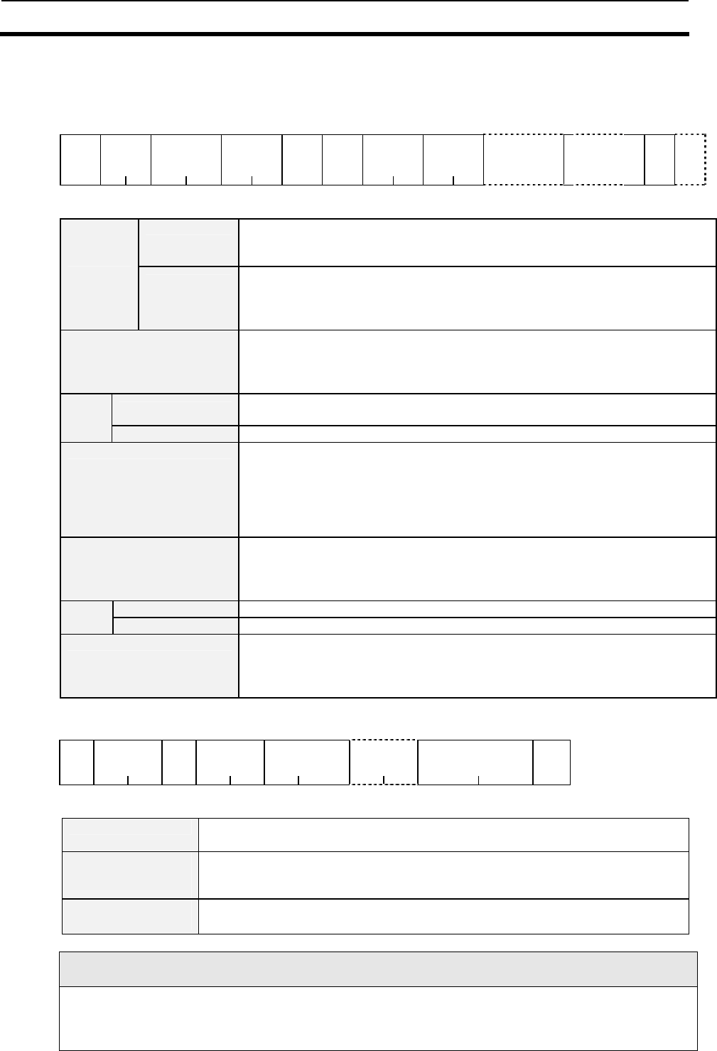
5-4 Communication Commands 5-4
5-33
5-4-5 Write (WT)-UID Select/Specified Tag
This command writes data to the Tag of either UID (SNR) (in ISO mode) or Temporary Number (in
I.CODE1 mode).
<Command Format>
STX
Node
No..
Command code
“WT”
Communi
cations
method
Data
type
Tag
type
First
write page
First
write page
UID(SNR) Write
data
ETX BCC
1 2 2 2 1 1 2 2 16 As specified 1 1
In ISO mode
Specifies the communications method with a Tag.
SL: UID (SNR) select
* Refer to SECTION 5-3-4 Communication Mode List for details.
Communic
ations
method
In I.CODE1
mode
Specifies the temporary No. in hexadecimal to write to the Tags.
□□: Temporary No. (The value of □□ should be within the range of
00h to 7Fh)
* Refer to SECTION 5-3-4 Communication Mode List for details.
Data type Specifies whether the read data is represented in ASCII or HEX.
A: ASCII code
H: HEX code
*Refer to SECTION 5-3-6 Specifying a Data Code for details.
In ISO mode Specify the Tag type.
A: I.CODE SLI chip
Tag
type
* In I.CODE1 mode “0” fixed.
First write page Specifies the first page in hexadecimal to write to the Tags.
Specification range: 00 to FFh In ISO mode: I.CODE SLI chip
should be between 00 to 1Bh)
Specification range: FB to 0Ah (In I.CODE1 mode: The available
user area should be between FF page and 0A page)
*Refer to SECTION 2-4 Memory Map of Tag for details.
No. of read pages Specifies the number of the pages in hexadecimal to write to the Tags.
Specification range: 01 to FFh (In ISO Mode: I.CODE SLI chip
should be from 01 to 1Ch)
Specification range: 01 to 0Eh (In I.CODE1 Mode)
In ISO mode Specifies UID (SNR) in hexadecimal to write to the Tags.
UID
(SNR) In I.CODE1 mode Not added.
Write data Indicates data to write to the Tag. The number of characters of the
data is as follows.
ASCII Code: No. of write pages x 4
HEX code: No. of write pages x 8
* Tag Type Setting is valid in the operating mode setting range of Reader/Writer.
<Response Format>
STX Node No..
Retry
flag
Command code
“WT”
Response code
“00”
Temporary
No.
ETX BCC
1 2 1 2 2 2 16 1 1
Response code 00:normal completion
For other response codes, refer to 5-3-7 Response code List.
Temporary number
(I.CODE1 Mode
only)
Returns the Temporary numbers from 00 to 7F in the normal state.
UID/SNR
(ISO Mode only)*
UID/SNR is added at the top of read data when UID/SNR addition setting is
enabled.
* UID/SNR is not added in I.CODE1 mode regardless of the UID/SNR addition setting status.
I.CODE1 SYSTEM AREA
From Page FD to Page FF is a system area for write-protect and QUIET/EAS settings. Depending on the
content of write data, a Tag may become write-protected or inaccessible, so be sure to understand these
pages fully before use.It is strongly recommended that you use a system command to write in these pages
(refer to 5-5) rather than using the write command.
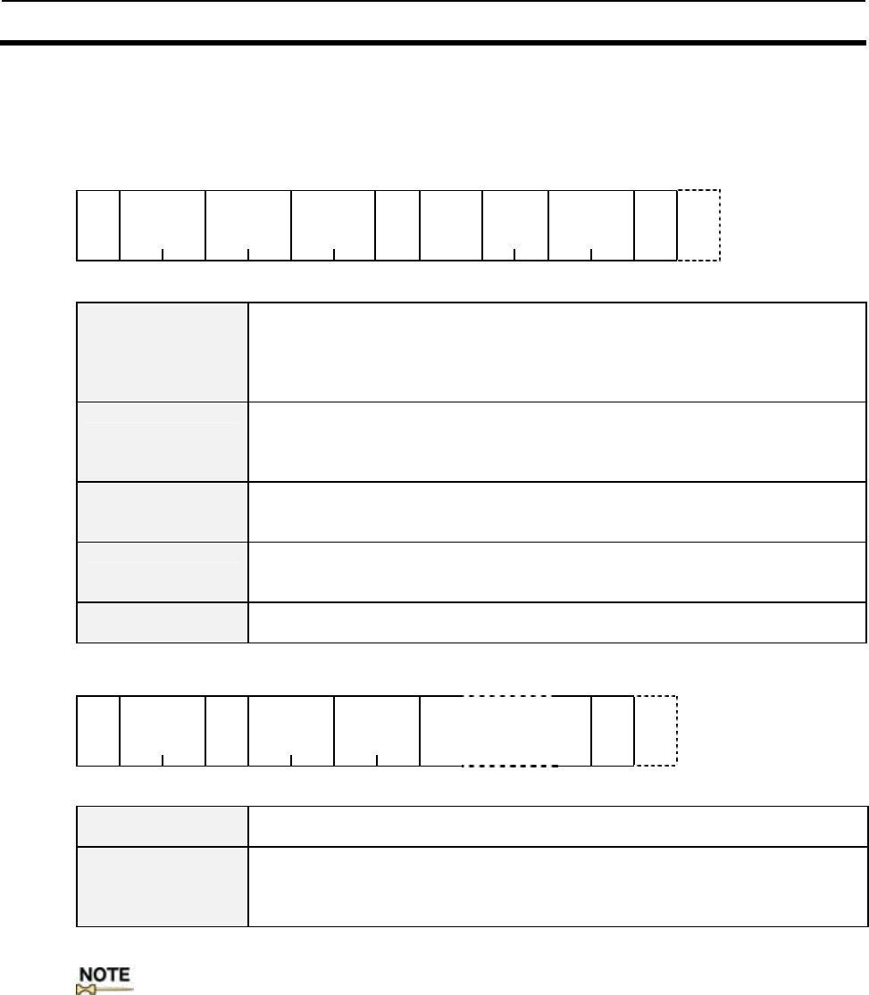
5-4 Communication Commands 5-4
5-34
5-4-6 Read (RD)-Fast Read Access: I.CODE1 Mode only
When there is only a single Tag in the communications area, this command enables to read data from the
Tag faster than a usual Read.
<Command Format>
STX
Node No..
Command
code
“RD”
Communi
cations
method
Data
type
Setting
Tag
No.
First
read
page
No. of
read pages
ETX BCC
1 2 2 2 1 1 2 2 1 1
Communications
method
Specifies the communications method with a Tag.
UT: Special Read Trigger
UA: Special Read Auto
UR: Special Read Repeat
* Refer to SECTION 5-3-4 Communication Mode List for details.
Data type Specifies whether the read data is represented in ASCII or HEX.
A : ASCII code
H : HEX code
* Refer to SECTION 5-3-6 Specifying a Data Code for details.
Tag No. setting Set the number of Tags which communicate simultaneously.
* Refer to SECTION 5-2-5 Specifying a Tag Code: I.CODE1 for details.
Specification range: 0 to 7
First read page Specifies the first page in hexadecimal to read from the Tags.
Specification range: FB to 0A (when Block 4 for a Philips product is
used as the user memory, refer to 2-4 of Section 2 Memory Map of Tag)
No. of read pages Specifies the number of pages from which data is read in hexadecimal.
Specification range: 01 to 10
<Response Format>
STX Node No..
Retry
flag
Command
code
“RD”
Response
code
“00”
Read data
ETX BCC
1 2 1 2 2
As specified 1 1
Response code 00:normal completion
For other Response Codes, refer to SECTION 5-3-7 Response Code List.
Read data Indicates data having read from the Tag. The number of characters of
the data is as follows.
ASCII Code: No. of write pages x 4
HEX code: No. of write pages x 8
:In Fast Read Access, multiple Tags can be read in the same way as in Multiple Repeat mode by
setting the Tag code other than 0 and specifying UR as the communication method. However, data is
repeatedly read while the Tag is in the communication area. (Refer to SECTION 3-2-5).
When UT or UA is specified as the communication method, the anti-collision processing (the operation to
prevent the collision of the response returned by the Tag), it is not performed even if a number other than
0 is specified as the Tag code. Therefore, if a collision (of the response) takes place, its Tag data cannot be
read. It is recommended that the command be used in Multiple Access mode (MT/MR). The command is
available in I.CODE1 Mode only; it is not available in ISO Mode.
5-4 Communication Commands 5-4
5-35
5-4-7 Polling Single Auto Read (PR)
Immediately after receiving the Polling Single Auto Read Command, the Reader/Writer returns a
response indicating the acceptance of the command, and waits for a Tag to enter the communications area
of the Antenna. Then it reads the data of the entering Tag. The host can inquire of the Reader/Writer
about the results of communications processing using the Polling Check (PC) command.
<Command Format>
STX
Node No..
Command code
“PR”
Data
type
Tag
type
First read
page
No. of
read
pages
ETX BCC
1 2 2 1 1 2 2 1 1
Data type Specifies whether the read data is represented in ASCII or HEX.
A : ASCII code
H : HEX code
* Refer to SECTION 5-3-6 Specifying a Data Code for details.
In ISO mode Specify the Tag type.
A: I.CODE SLI chip
Tag
type
* In I.CODE1
mode Not added.
First read page Specifies the first page in hexadecimal to read data from the Tags.
Specification range: 00 to FFh (In ISO mode: I.CODE SLI chip
should be from 00 to 1Bh)
Specification range: FB to 0Ah (In I.CODE1 mode)
* Refer to SECTION 2-4 Memory Map of Tag for details.
No. of read pages Specifies the number of the pages in hexadecimal to read data from
the Tags.
Specification range: 01 to FFh (In ISO mode: I.CODE SLI chip
should be from 01 to 1Ch)
Specification range: 01 to 10h (In I.CODE1 mode)
* Tag Type Setting is valid in the operating mode setting range of Reader/Writer.
<Response Format>
STX Node No..
Retry
flag
Command code
“PR”
Response
code
“74”
ETX BCC
1 2 1 2 2 1 1
Response code 74: Command acceptance
For other Response Codes, refer to SECTION 5-3-7 Response Code List.
5-4 Communication Commands 5-4
5-36
5-4-8 Polling Single Auto Write (PW)
Immediately after receiving the Polling Single Auto Write Command, the Reader/Writer returns a
response indicating the acceptance of the command and waits for a Tag to enter the communications area
of the Antenna. Then it writes data to the entering Tag. The host can inquire of the Reader/Writer about
the results of communications processing using the Polling Check (PC) command.
There is no need to perform the verify read process, since this command performs it as part of its
execution.
<Command Format>
STX
Node No..
Command
code
“PW”
Data
type
Tag
type
First write
page
No. of
write
pages
Write data ETX BCC
1 2 2 1 1 2 2 As specified 1 1
Data type Specifies whether the write data is represented in ASCII or HEX.
A : ASCII code
H : HEX code
* Refer to SECTION 5-3-6 Specifying a Data Code for details.
In ISO mode Specify the Tag type.
A: I.CODE SLI chip
Tag
type
* In I.CODE1
mode Not added.
First write page Specifies the first page in hexadecimal to write data to the Tags.
Specification range: 00 to FFh (In ISO mode: I.CODE SLI chip
should be from 00 to 1Bh)
Specification range: FB to 0Ah (In I.CODE1 mode: the range of the
writable user area is FF page to 0A page)
* Refer to SECTION 2-4 Memory Map of Tag for details.
No. of read pages Specifies the number of the pages in hexadecimal to write data to the
Tags.
Specification range: 01 to FFh (In ISO Mode: I.CODE SLI chip
should be from 01 to 1Ch)
Specification range: 01 to 0Eh (In I.CODE1 Mode)
Write data Indicates data to write to the Tag. The number of characters of the
data is as follows.
ASCII Code: No. of write pages x 4
HEX code: No. of write pages x 8
* Tag Type Setting is valid in the operating mode setting range of Reader/Writer.
<Response Format>
STX Node No.. Retry
flag
Command
code
“PW”
Response
code
“74”
ETX BCC
1 2 1 2 2 1 1
Response code 74: Command acceptance
For other Response Codes, refer to SECTION 5-3-7 Response Code List.
I.CODE1 SYSTEM AREA
The pages from FD to FF on the I.CODE1 Chip are system areas for setting write access conditions,
QUIET/EAS, family code/application ID. Users must understand thoroughly how the function works
because the Tag may be locked or access may be disabled depending on data written to the area. It is
strongly recommended that data be re-written using a command dedicated to system area writing rather
than Write Command (Refer to SECTION 5-5).
5-4 Communication Commands 5-4
5-37
5-4-9 Polling Check (PC)
You can check the results while the Polling Single Auto Read Command and Polling Single Auto Write
Command are being executed. You can use Polling Check after the Polling Single Auto Read Command
and Polling Single Auto Write Command have been sent.
<Command Format>
STX
Node No..
Command
code
“PC”
ETX BCC
1 2 2 1 1
<Response Format>
(1) Response to Polling Single Auto Read Command (PR)
STX Node No..
Retry
flag
Command
code
“PR”
Response
code
“00”
UID(SNR) Read data
ETX BCC
1 2 1 2 2 16 As specified 1 1
(2) Response to Polling Single Auto Write Command (PW)
STX Node No..
Retry
flag
Command
code
“PW”
Response
code
“00”
UID(SNR) ETX BCC
1 2 1 2 2 16 1 1
(3) Response when a Tag is not detected
A response when Polling Check Command is received before the communications with a Tag is
completed.
STX Node No..
Retry
flag
Command code
“PC”
Response
code
“74”
ETX BCC
1 2 1 2 2 1 1
Response code 00:normal completion
74: In a case before the communications with a Tag is completed.
For other Response Codes, refer to SECTION 5-3-7 Response Code List.
UID (SNR) Indicates UID (SNR) data having read from a tag.
UID (SNR) (Tag-specified code) additional setting (refer to 5-6-5 SN
Command) is added when it is valid as follow
• Polling Single Auto Read: UID (SNR) is added before Read data.
• Polling Single Auto Write: When it is in ISO mode, UID (SNR) is
added after the Response code “00.”
Read data Indicates data to read from the Tag. The number of characters of the
data is as follows.
ASCII Code: No. of write pages x 4
HEX code: No. of write pages x 8
5-4 Communication Commands 5-4
5-38
5-4-10 Polling End (PE)
This command aborts the execution of Polling commands. It is used after a Polling command is
sent.
<Command Format>
STX
Node No..
Command
code
“PE”
ETX BCC
1 2 2 1 1
<Response Format>
(1) Before the completion of communications with a Tag
STX Node No..
Retry
flag
Command
code
“PE”
Response
code
“75”
ETX BCC
1 2 1 2 2 1 1
(2) After the completion of communications with a Tag
STX Node No..
Retry
flag
Command
code
“PE”
Response
code
“76”
ETX BCC
1 2 1 2 2 1 1
Response code 75:Before the completion of communications with a Tag
76:After the completion of communications with a Tag
For other response codes, refer to 5-3-7 Response code List.
5-4 Communication Commands 5-4
5-39
5-4-11 Memory Check (MC): I.CODE1 Mode only
This command uses the generating polynomial, X16 + X12 + X5 + 1 to calculate the range of the check block
designated by a user and to compare the results with the check code attached to the check block.
<Command Format>
STX
Node No..
Command code
“MC”
Check
block.
header page
Check block
No. of pages
ETX BCC
1 2 2 2 2 1 1
Check block
Header page
Specifies the header page of check block in hexadecimal.
Specify the top page of the check block in hex number. Specification
range: FF to 09 (When using the Philips block 4 as the user memory,
refer to SECTION 2-4).
Check block
No. of pages
Specifies the number of the pages of check block in hexadecimal.
Specification range: 02 to 0C
<Response Format>
STX Node No..
Retry
flag
Command code
“MC”
Response
code
ETX BCC
1 2 1 2 2 1 1
Response code 75: When the check results are correct
76: When the check results are incorrect
For other Response Codes, refer to SECTION 5-3-7 Response Code List.
:This command is for I.CODE1 Mode Only. The command is not available in ISO mode.
5-4-12 Memory Calculation (MK): I.CODE1 Mode only
This command uses the generating polynomial, X16 + X12 + X5 + 1 to calculate the range of the
check block designated by a user and writes the check code to the last page of the check block.
<Command Format>
STX
Node No..
Command
code
“MK”
Check
block.
header
page
Check
block
No. of
pages
ETX BCC
1 2 2 2 2 1 1
Check block
header page
Specifies the header page of check block in hexadecimal.
Specify the top page of the check block in hex number. Specification
range: FF to 09 (When using the Philips block 4 as the user memory,
refer to Chapter 2, SECTION 2-4 Memory Map of Tag).
Check block
No. of pages
Specifies the number of the pages of check block in hexadecimal.
Specification range: 02 to 0C
<Response Format>
STX Node No..
Retry
flag
Command
code
“MK”
Response
code
“00”
ETX BCC
1 2 1 2 2 1 1
Response code 00:normal completion
For other Response Codes, refer to SECTION 5-3-7 Response Code List.
:This command is for I.CODE1 Mode Only. The command is not available in ISO mode.
5-5 System Command 5-5
5-40
5-5-1 System Read (SR): ISO Mode only
This command read system information in the system area of the Tag.
<Command Format>
STX
Node No..
Command
code
“SR”
Tag
type
System
method
“00
”
ET
X
BC
C
1 2 2 1 2 1 1
Tag type Specified a Tag type
A: I.CODE SLI chip
System method Specified the kind of system information.
“00” fixed.
<Response Format>
STX Node No..
Retry
flag
Command
code
“SR”
Response
code
“00”
Information
flag
UID(SNR)
Information
field
ETX BCC
1 2 1 2 2 2 16 2to10 1 1
Response code 00:normal completion
For other Response Codes, refer to SECTION 5-3-7 Response Code List.
Information flag Indicates information in the Information field with a flag.
Bit Information
0 DSFID
1 AFI
2 VICC memory size
3 IC reference information
4to7 For future use
* Information field is stored in order of bit when the bit above is 1.
* For the contents of information flag, refer to 2-4 Memory Map.
UID(SNR) Indicates UID (SNR) data having read from a Tag.
DSFID DSFID of a Tag
AFI AFI of a Tag
VICC
memory size
Defines the memory and block sizes of a Tag.
MSB LSB
15 13 12 8 7 0
Un-
assigned Block size Block length
* Block length: the number of blocks of a Tag(00h to FFh=1 to 256)
* Block size: the number of bytes per one block(00h to 1Fh=1 to 32)
<As for I.CODE SLI chip: “1B03”>
Block length: “1B”=28 blocks
Block size: “03”= 4 bytes
Information field
IC reference
information
IC reference Information of Tag
* IC reference Information is a form of data defined by IC manufacturer.
:This command is in ISO Mode Only. The command is not available for I.CODE1 mode.
5-5 System Command 5-5
5-41
5-5-2 System Write (SW): ISO Mode only
This command writes the settings of AFI, DSFID, and EAS to a Tag.
<Command Format>
(1) For normal write
STX
Node No..
Command code
“SW”
Tag
type
System
method
data
ETX BCC
1 2 2 1 2 2 1 1
(2) When UID of a Tag is specified
STX
Node No..
Command
code
“SW”
Tag
type
System
method
UID
data
ET
X
BC
C
1 2 2 1 2 16 2 1 1
Tag type Specifies the Tag type.
A: I.CODE SLI chip
System method Specifies the kind of system information to write to.
01: AFI
02: DSFID
03: EAS (For normal write)
83: Select EAS (When specifying UID of a Tag)
UID Specifies UID of a Tag in hexadecimal to write to.
AFI Specifies UID of a Tag in hexadecimal to write to.
Specification range: 00 to FFh
DSFID Specifies UID of a Tag in hexadecimal to write to.
Specification range: 00 to FFh
Data
EAS
setting
00: Enables EAS setting
01: Disables EAS setting
<Response Format>
STX Node No..
Retry
flag
Command code
“SW”
Response code
“00”
ETX BCC
1 2 1 2 2 1 1
Response code 00:normal completion
For other Response Codes, refer to SECTION 5-3-7 Response Code List.
:This command is in ISO Mode Only. The command is not available for I.CODE1 mode.
5-5 System Command 5-5
5-42
5-5-3 System Lock (SL): ISO Mode only
This command locks (write-inhibit) to write to system area information of a Tag.
<Command Format>
(1) Normal lock
STX
Node No..
Command code
“SL”
Tag
type
System
method
ETX BCC
1 2 2 1 2 1 1
(2) In a case where UID of a Tag is specified
STX
Node No..
Command code
“SL”
Tag
type
System
method
UID
ETX BCC
1 2 2 1 2 16 1 1
Tag type Specifies the Tag type.
A: I.CODE SLI chip
System method Specifies the system information to lock.
01:AFI
02: DSFID
03: EAS (normal lock)
83: Select EAS (In a case where UID of a Tag is specified and locked)
UID Specifies the UID of a Tag to lock in hexadecimal.
<Response Format>
STX Node No..
Retry
flag
Command
code
“SL”
Response
code
“00”
ETX BCC
1 2 1 2 2 1 1
Response code 00:normal completion
For other Response Codes, refer to SECTION 5-3-7 Response Code List.
(Important) Precautions on the Lock function
Be careful that once system information has been locked, the lock cannot be cleared.
:This command is in ISO mode Only. The command is not available for I.CODE1 mode.
5-5 System Command 5-5
5-43
5-5-4 Read (RD)-SNR Read: I.CODE1 Mode only
This command read SNR (Tag-specified code) which incorporates I.CODE1 chip. Refer to 2-4 of Section 2
Memory Map of Tag.
<Command Format>
STX
Node No..
Command code
“RD”
Communications
method
Data
type
Tag
No.
setting
Fixed
value
“∗∗”
Fixed
value
“((”
ETX BC
C
1 2 2 2 1 1 2 2 1 1
Communications
method
Specifies the communications
method with a Tag.
ST: Single Trigger
SA: Single Auto
SR: Single Repeat
FT: FIFO Trigger
FR: FIFO Repeat
MT: Multi-trigger
MR: Multi-repeat
LT: Selective Access (Tag detection)
□□: Selective Access (Read)
(For □□, the values from 00h to 7Fh
are available.)
UT: Special Read Trigger
UA:: Special Read Auto
UR: Special Read Repeat
Refer to SECTION 5-3-4
Communication Mode List for details.
Data type “H” fixed (HEX code)
For Single/FIFO/Selective Access (Read)
Set the number of Tags “0.”
Tag No. setting
For Multi/Selective Access (Tag detection command)
Reads SNR (unique code of the Tag) on the Tags with an I.CODE1 Chip.
Refer to SECTION 5-2-5, Specifying a Tag Code.
Specification range: 1 to 7
<Response Format>
(1) For Single/FIFO/Multi (except for the response of the completion of communications)
STX Node No..
Retry
flag
Command code
“RD”
Response
code
“00”
Serial
No.
ETX BCC
1 2 1 2 2 16 1 1
(2) For Selective Access (except for the response of the completion of Tag detection)
STX Node No..
Retry
flag
Command code
“RD”
Response
code
“00”
Temporary
No.
Serial
No.
ETX BCC
1 2 1 2 2 2 16 1 1
Response code 00:normal completion
For other Response Codes, refer to SECTION 5-3-7 Response Code List.
Serial No. Indicates serial number written to a Tag in advance. You cannot rewrite
the number.
:This command is for I.CODE1 Mode Only. The command is not available in ISO mode:
5-5 System Command 5-5
5-44
5-5-5 EAS Setting (ES): I.CODE1 Mode only
This command sets the EASBit of a Tag incorporating I.CODE1 chip. When the EASBit is
disabled, the Reader/Writer will not return a response to the EAS Check Command (EA).
<Command Format>
STX
Node No..
Command code
“ES”
Setting ETX BCC
1 2 2 2 1 1
Setting Specification range:00to01
00:EAS enabled
01:EASdisabled
<Response Format>
STX Node No..
Retry
flag
Command code
“ES”
Response
code
“00”
ETX BCC
1 2 1 2 2 1 1
Response code 00:normal completion
For other Response Codes, refer to SECTION 5-3-7 Response Code List.
:The relative commands are set in offline mode (refer to 5-7-12 FL Command). This command is
for I.CODE1 mode Only. The command is not available in ISO mode.
5-5-6 QuietBit Setting (QB): I.CODE1 Mode only
This command sets QuietBit of a Tag incorporating I.CODE1 chip. If you enable this bit, a Tag
ceases to return a response to any command (excluding the EAS Command).
<Command Format>
STX
Node No..
Command code
“QB”
Setting ETX BCC
1 2 2 2 1 1
Setting Specification range:00h to 01h
00: Disable QuietBit
01: Enable QuietBit
<Response Format>
STX Node No..
Retry
flag
Command
code
“QB”
Response
code
“00”
ETX BCC
1 2 1 2 2 1 1
Response code 00:normal completion
For other Response Codes, refer to SECTION 5-3-7 Response Code List.
:This command is for I.CODE1 Mode Only. The command is not available in ISO mode.
5-5 System Command 5-5
5-45
5-5-7 Lock Setting (LK): ISO Mode
This command is used to set and check the write-protection of Tags incorporating I.CODE1 chip.
A Tag can be locked (or write-protected) by memory page.
<Command Format>
STX
Node No..
Command code
“LK”
Tag
type
First lock page lock
No. of pages
ETX BCC
1 2 2 1 2 2 1 1
Tag type Specifies Tag type.
A: I.CODE SLI chip
First lock page
Specifies the first page to be locked in hexadecimal.
Specification range: 00 to FFh
* For details, refer to 2-4 Memory Map of Tag.
No. of lock pages
Specifies the first lock page t in hexadecimal.
Specification range: 01h to 1Ch
<Response Format>
STX Node No.. Retry
flag
Command code
“LK”
Response
code
“00”
ETX BCC
1 2 1 2 2 1 1
Response code 00:normal completion
For other response codes, refer to 5-3-7 Response code List.
(Important) Precautions on the Lock function
Be careful that once a lock is set, the lock cannot be cleared.
:This command is for ISO mode Only. The command is not available in I.CODE1 mode, refer to
5-5-9.
5-5 System Command 5-5
5-46
5-5-8 Lock Setting Read (LR): ISO Mode only
This command reads lock setting information of a Tag incorporating I.CODE SLI chip.
<Command Format>
STX
Node No..
Command code
“LR”
Tag
type
First lock page No. of lock
pages
ETX BCC
1 2 2 1 2 2 1 1
Tag type Specifies Tag type.
A: I.CODE SLI chip
First lock page
Specifies the first page, which reads lock information, in hexadecimal.
Specification range: 00 to FFh (I.CODE SLI chip: 00 to 1Bh)
*Refer to SECTION 2-4 Memory Map of Tag for details.
No. of lock pages
Specifies the number of pages, from which reads lock information, in
hexadecimal.
Specification range: 01h to FFh (I.CODE SLI chip: 01 to 1Ch)
<Response Format>
STX Node No.. Retry
flag
Command code
“LR”
Respons
code
“00”
Lock Information
ETX BCC
1 2 1 2 2
No. of lock pages
1 1
Response code 00:normal completion
For other Response Codes, refer to SECTION 5-3-7 Response Code List.
Lock information Indicates lock information having read from Tag.
Locked:”01”
Not locked :”00”
The number of characters of the data: “read pages x 2.
: This command is for ISO Mode Only. The command is not available in I.CODE1mode.
5-5 System Command 5-5
5-47
5-5-9 Lock Setting (LK): I.CODE1 Mode
This command is used to set and check the lock (write-protection) of Tags incorporating
I.CODE1 chip. A Tag can be locked (or write-protected) by memory page. To read lock
information set in a Tag, set all lock information in the commands to 0.
<Command Format>
STX
Node No..
Command code
“LK”
Lock setting ETX BCC
1 2 2 4 1 1
Lock setting
Set the bit corresponding to the page you want to lock to 1. *See the
table below.
<Lock setting check>
Set all lock settings to 0 to read the lock information in a Tag.
* The lock information for each page is represented by a 1-bit datum.
Lock setting
b7 b6 b5 b4 b3 b2 b1 b0 b7 b6 b5 b4 b3 b2 b1 b0
Page
10
Page
9
Page
8
Page
7
Page
6
Page
5
Page
4
Page
3
Page
2
Page
1
Page
0
A
I
,F
C
E Q
A U
S I
E
T
Write
-
protect
S
N
R
S
N
R
AI: Application ID FC: Family Code
<Response Format>
STX Node No.. Retry
flag
Command code
“LK”
Response
code
“00”
Lock setting Information ETX BCC
1 2 1 2 2 4 1 1
Response code 00:normal completion
For other Response Codes, refer to SECTION 5-3-7 Response Code List.
Lock setting
Information
Indicates lock information set in a Tag.
Description: This is an example of command and response when locking pages 1, 3, 7, and 8 in a Tag in
which page 10 has already been locked. This example does not include STX, ETX, BCC,
and the node number. The lock setting in the response included information concerning
the pages that have already been locked.
Command: LK3140
Response: LK00B143
:SNR (Tag-specific code) is locked at factory. SNR 2 bit in the lock setting in the response is
always on.
(Important) Precautions on the Lock function
Use utmost care when using the LK Command because once a page has been locked, it cannot be
unlocked. It is strongly recommended that you use a system command to lock a page rather than using
this command.
:This command is for I.CODE1 Mode Only. The command is not available in ISO mode, refer to
5-5-7.
5-5 System Command 5-5
5-48
5-5-10 EAS Check (EA)
This command transmits the EAS command continuously and returns the percentage of data
that matches the EAS response code.
<Command Format>
1)In ISO mode
STX
Node No..
Command code
“EA”
Tag
type
ETX BCC
1 2 2 1 1 1
2)In I.CODE1 mode
STX
Node No..
Command code
“EA”
ETX BCC
1 2 2 1 1
Tag type
(ISO mode)
Specifies Tag type.
A: I.CODE SLI chip
* Not added in I.CODE1 mode.
<Response Format>
STX Node No..
Retry
flag
Command code
“EA”
Response
code
“00”
Ratio ETX BCC
1 2 1 2 2 2 1 1
Response code 00:normal completion
For other Response Codes, refer to SECTION 5-3-7 Response Code List.
Ratio Indicates the ratio of data that matches the EAS response code in
hexadecimal.
(00h to 64h[%])
How to use properly
1) In some cases, this command will not indicate 0% even though there are no Tags. Be sure take this
into account when determining the presence or absence of Tags.
2) The EAS Check Command works as a repeat command. After this command is sent once, only a
response will be returned. To discontinue transmission of this command, you need to use the Stop
Command (refer to ST Command in 5-6-1).
5-6 Reader/Writer Control Commands 5-6
5-49
5-6-1 Stop (ST)
Stop (ST) Stop command terminates Auto mode, Repeat mode, EAS check and other command
processings, as well as continued FIFO state after FIFO Access, or Select state after executing
Detection command, returning to the Reader/Writer to a stand-by status to wait for commands.
<Command Format>
STX
Node No.
Command
code
"ST"
ETX BCC
1 2 2 1 1
<Response Format>
STX Node No.
Retry
flag
Command
code
"ST"
Response
code
"00"
ETX BCC
1 2 1 2 2 1 1
Response code 00: Normal completion
For other response codes, refer to 5-3-7Response Code List.
5-6-2 Reset (XZ)
Reset Command resets the Reader/Writer software. No response is returned for this command.
Other commands are rejected during the software reset process (approximately 2.5 seconds).
<Command Format>
STX
Node No.
Command
code
"XZ"
ETX BCC
1 2 2 1 1
5-6-3 ACK(AK)
This command is used during ACK/NACK control to inform the Reader/Writer that the host device
normally received a response from the Reader/Writer. There is no response if this command is used in
ACK/NACK control, but if the Reader/Writer is not waiting to receive ACK/NACK signals, an error will
occur when the command is received. Refer to SECTION 5-1-3 ACK/NACK Control for details.
<Command Format>
STX
Node No.
Command
code
"AK"
ETX BCC
1 2 2 1 1
5-6-4 NACK(NK)
This command is used during ACK/NACK control to inform the Reader/Writer that the host device did not
normally receive a response from the Reader/Writer. When the Reader/Writer receives a NACK command,
the previous response is retried provided that the maximum number of retries (9) has not been exceeded.
If the Reader/Writer is not waiting to receive ACK/NACK signals, an error will occur when the
command is received. Refer to SECTION 5-1-3 ACK/NACK Control for details.
<Command Format>
STX
Node No.
Command
code
"NK"
ETX BCC
1 2 2 1 1
5-6 Reader/Writer Control Commands 5-6
5-50
5-6-5 I/O Control Command (CC)
This command changes the state of the user output terminals (OUT1 to OUT4) and reads the state of the
user input terminals (IN1 to IN3).
<Command Format>
STX
Node No.
Command
code
"CC"
OUT
1
OUT
2
OUT
3
OUT
4
ETX BCC
1 2 2 1 1 1 1 1 1
OUT1to OUT4
The state of an output is designated in hexadecimal.
Specification range: 0 to 1 (1: ON / 0: OFF)
When * is specified, the Reader/Writer reads the state of a terminal.
<Response Format>
STX
Node No.
Retry
flag
Command
code
"CC"
Response
code
"00"
OUT
1
OUT
2
OUT
3
OUT
4
IN
1
IN
2
IN
3
ETX BCC
1 2 1 2 2 1 1 1 1 1 1 1 1 1
Response code 00: Normal completion
For other Response Codes, refer to SECTION 5-3-7 Response Code List.
OUT1 to OUT4 Indicates the state of the output.
1: ON, 0: OFF
IN1 to IN3 Indicates the state of the input.
1: ON, 0: OFF
5-6-6 Test (TS)
This command returns test messages sent from the host with no change made. The test
command is used for testing communications between the host and the Reader/Writer and
other purposes.
<Command Format>
STX
Node No.
Command
code
"TS"
Test message ETX BCC
1 2 2 1 1
Test message The number of characters from 0 up to 64 max is available.
<Response Format>
STX Node No.
Retry
flag
Command
code
"TS"
Response
code
"00"
Test message ETX BCC
1 2 1 2 2 1 1
Response code 00: Normal completion
For other Response Codes, refer to SECTION 5-3-7 Response Code List.
Test message Returns the test message received using commands.
5-6 Reader/Writer Control Commands 5-6
5-51
5-6-7 Version (VS)
This command reads the software version for the Reader/Writer.
<Command Format>
STX
Node No.
Command
code
"VS"
ETX BCC
1 2 2 1 1
<Response Format>
STX Node No.
Retry
flag
Command
code
"VS"
Response
code
"00"
Software version ETX BCC
1 2 1 2 2 4 1 1
Response code 00: Normal completion
For other Response Codes, refer to SECTION 5-3-7 Response Code List.
5-7 Setting Command 5-7
5-52
5-7-1 Reader/Writer AFI Enable/Disable Changeover (AE): ISO Mode only
In ISO mode, you must set AFI of the Reader/Writer either enable or disable when communicating with a
Tag. If you set AFI enable, only Tags, which has the same AFI, can be communicated. When you set AFI
disable, the communications are enabled no matter AFI in Reader/Writer is set or not.
<Command Format>
STX
Node No..
Command code
“AE”
AFI
Setting
ETX BCC
1 2 2 1 1 1
AFI
enable/disable
Specifies either valid or invalid of AFI setting in Reader/Writer.
0: disabled (factory setting)
1: enabled
For “*”, the Reader/Writer reads and writes current settings.
<Response Format>
STX Node No..
Retry
flag
Command code
“AE”
Response
code
“00”
AFI
Setting
ETX BCC
1 2 1 2 2 1 1 1
Response code 00:normal completion
For other Response Codes, refer to SECTION 5-3-7 Response Code List.
AFI valid/invalid Indicates valid/invalid of AFI in hexadecimal.
: ・A setting becomes valid after executing Reset Command(XZ). To keep the setting valid next
startup, you need to save with Setting Write Command(EW).
・This command is for ISO Mode Only. The command is not available in I.CODE1 mode.
5-7-2 Reader/Writer AFI Value setting (AF): ISO Mode only
In ISO mode, you must set and read AFI of the Reader/Writer. When you set AFI enable, only Tags, which
has the same AFI, can be communicated. When the setting is “00”, the communications are enabled.
<Command Format>
STX
Node No..
Command code
“AF”
AFI
ETX BCC
1 2 2 1 1 1
FI
Specifies AFI in hexadecimal.
Specification range:00h to FFh (factory setting “00”)
For “**”, the Reader/Writer reads and writes current setting of AFI.
<Response Format>
STX Node No..
Retry
flag
Command code
“AF”
Response
code
“00”
AFI
ETX BCC
1 2 1 2 2 1 1 1
Response code
00: normal completion
For other Response Codes, refer to SECTION 5-3-7 Response Code List.
AFI Specifies AFI in hexadecimal.
:・A setting becomes valid after executing Reset Command. To keep the setting valid next
startup, you need to save with Setting Write Command (EW).
・This command is for ISO Mode Only. The command is not available in I.CODE1 mode.
5-7 Setting Command 5-7
5-53
5-7-3 Reader/Writer Family Code Setting (FC): I.CODE1 Mode
The FC Command is used to set or read the Family Code in the Reader/Writer. Only Tags that have the
same Family Code as the one set by this command can perform communications. If this Family Code is set
to 00, communications will be possible with all Tags. The default set value of the Reader/Writer is 00.
<Command Format>
STX
Node No..
Command code
“FC”
Family
Code
ETX BCC
1 2 2 2 1 1
Family Code The Family Code is designated in hexadecimal.
Specification range: 00h to FFh (factory setting: ”00”)
When the Family Code set to " ," the Family Code currently set in the
Reader/Writer will be read.
<Response Format>
STX Node No..
Retry
flag
Command code
“FC”
Response
code
“00”
Family
Code
ETX BCC
1 2 1 2 2 2 1 1
Response code 00:normal completion
For other Response Codes, refer to SECTION 5-3-7 Response Code List.
Family Code Indicates current Family Code in hexadecimal.
:・A setting becomes valid after executing Reset Command(XZ). To keep the setting valid next
startup, you need to save with Setting Write Command (EW).
・This command is for I.CODE1 Mode Only. The command is not available in ISO mode.
5-7-4 Reader/Writer Application ID Setting (AI): I.CODE1 Mode
This Command is used to set or read and read the application ID in the Reader/Writer in 1.CODE1 Mode
Only Tags that have the same application ID as the one set by this command can perform communications.
If the application ID in the Reader/Writer is set to 00, communications will be possible with all Tags.
<Command Format>
STX
Node No..
Command code
“AI”
Application
ID
ETX BCC
1 2 2 2 1 1
Application ID
The application ID is designated in hexadecimal.
Specification range: 00h to FFh
When the application ID is set to "**," the application ID currently set in
the Reader/Writer will be read.
<Response Format>
STX Node No..
Retry
flag
Command
code
“AI”
Response
code
“00”
Application
ID
ETX BCC
1 2 1 2 2 2 1 1
Response code 00:normal completion
For other Response Codes, refer to SECTION 5-3-7 Response Code List.
Application ID
Indicates current Application I in hexadecimal.
:・A setting becomes valid after executing Reset Command(XZ). To keep the setting valid next
startup, you need to save with Setting Write Command(EW).
・This command is for I.CODE1 Mode Only. The command is not available in ISO mode.
5-7 Setting Command 5-7
5-54
5-7-5 UID/ SNR Addition Setting (SN)
This command selects whether SNR will be added to a response to a Read Command
(excluding Special Read).
<Command Format>
STX
Node No.
Command
code
"SN"
Additi
on
mode
ETX BCC
1 2 2 1 1 1
Specify whether SNR will be added to a response.
Setting range: 0 to 1, or *
When * is specified, the Reader/Writer reads the number that is
currently set.
Specification
number
0 1 *
Addition mode
UID(SNR)
addition mode
Disabled Enabled -
<Response Format>
STX Node No. Retry
flag
Command
code
"SN"
Response
code:
"00"
Addit
ion
mode
ETX BCC
1 2 1 2 2 1 1 1
Response code: 00: Normal completion
For other response codes, refer to 5-3-7 Response Code List.
addition mode Indicates the number corresponding to the specified addition mode.
<Response when setting is invalid>
STX Node No. Retry
flag
Command
code
"RD"
Response
code:
"00"
Read data ETX BCC
1 2 1 2 2 As specified 1 1
<Response when setting is valid>
STX Node No. Retry
flag
Command
code
"RD"
Response
code:
"00"
UID(SNR) Read data ETX BCC
1 2 1 2 2 16 As specified 1 1
Response code: 00: Normal completion
For other response codes, refer to 5-3-7 Response Code List.
UID(SNR) Indicates the UID(SNR) read from the Tag.
Read data Indicates the data read from the Tag.
Precautions on using the command in I.CODE1 mode
・SNR is not added to the response for Fast Read Access (U□) even though UID/SNR addition setting is
enabled.
・The correct SNR value is not returned as a response by the Tag Designation Command even though
UID/SNR addition setting is enabled. The setting must be disabled or data in SNR area must be
ignored.
:・The setting is enabled after reset by the Reset Command(XZ). To enable the setting forthe
next start-up, the setting must be saved by Set Value Writing (EW).
5-7 Setting Command 5-7
5-55
5-7-6 Node Number Setting(NN)
This command sets and reads the node number of the Reader/Writer.
<Command Format>
STX
Node No.
Command
code
"NN"
Node number
change
specification
ETX BCC
1 2 2 2 1 1
Node number
change
specification
Specifies the node number in decimal that you want to change.
Specification range: 00 to 31, **
When “**” is specified, the Reader/Writer reads the current setting.
<Response Format>
STX Node No. Retry
flag
Command
code
"NN"
Response
code
"00"
Node number ETX BCC
1 2 1 2 2 2 1 1
Response code 00: Normal completion
For other Response Codes, refer to SECTION 5-3-7 Response Code List.
Node number Indicates the specified node number in decimal.
:・The setting is enabled after reset by the Reset Command(XZ). To enable the setting forthe
next start-up, the setting must be saved by Set Value Writing (EW).

5-7 Setting Command 5-7
5-56
5-7-7 Communications Port Setting(CP)
This command sets the baud rate for the communications port (Com Port), data length, parity
bit, and stop bit for use in communications with the host.
<Command Format>
STX
Node No.
Command
code
"CP"
Port
No.
Baud
rate
Data
length
Parit
y bit
Stop
bit
BCC
Enabled
/Disable
d
ACK
NAC
K
time
out
ETX BCC
1 2 2 1 1 1 1 1 1 1 1 1 1
Specify the port number that you want to change in decimal.
Specification range: 1 or 2
Specification number 1 2
Port No.
Port COM1 COM2
Specify the number corresponding to the baud rate that you want to change.
Specification range: 0 to 3, *
When * is specified, the Reader/Writer reads the current setting.
Specified
number 0 1 2 3 *
Baud rate
Baud rate 9600 bps 19200 bps 38400 bps 115200 bps -
Specify the number corresponding to the data length that you want to change.
Specification range: 0, 1, *
When * is specified, the Reader/Writer reads the current setting.
Specification number 0 1 *
Data length
Data length 7Bit 8Bit -
Specify the number corresponding to the parity bit that you want to change.
Specification range: 0, 1, 2, *
When * is specified, the Reader/Writer reads the current setting.
Specification
number 0 1 2 *
Parity bit
Parity No Odd Even -
Specify the number corresponding to the stop bit that you want to change.
Specification range: 0, 1, *
When * is specified, the Reader/Writer reads the current setting.
Specification number 0 1 *
Stop bit
Stop bit 1 bit 2 bits -
Specify the number corresponding to the BCC setting that you want to change.
Specification range: 0, 1, *
When * is specified, the Reader/Writer reads the current setting.
Specification number 0 1 *
BCC
Enabled/Disabled
BCC Disabled Enabled -
Specify the number corresponding to the communications mode that you want to change.
Specification range: 0, 1, *
When * is specified, the Reader/Writer reads the current setting.
Specification number 0 1 *
ACK/NACK
ACK/NACK Control Disabled Enabled -
Specify the number corresponding to the timeout period that you want to change.
Specification range: 0, 1, *
When * is specified, the Reader/Writer reads the current setting.
Specification number 0 1 *
Timeout
ACK/NACK timeout
period setting
Timeout period 0.5 sec 5 sec -
5-7 Setting Command 5-7
5-57
<Response Format>
STX
Node No.
Retry
flag
Command
code
"CP"
Response
code:
"00"
Port
No.
Baud
rate
Data
length
Parity
bit
Stop
bit
BCC
Enabled
/Disabled
ACK
NACK
Time
out
ETX BCC
1 2 1 2 2 1 1 1 1 1 1 1 1 1 1
Response code: 00: Normal completion
For other Response Codes, refer to Response Code List.
Port No. Indicates the number corresponding to the specified terminal resistance.
Baud rate Indicates the number corresponding to the specified baud rate.
Data length Indicates the number corresponding to the specified data length.
Parity bit Indicates the number corresponding to the specified parity bit.
Stop bit Indicates the number corresponding to the specified stop bit.
BCC
Enabled/Disabled
Indicates the number corresponding to the specified BCC setting.
ACK/NACK Indicates the number corresponding to the specified control mode.
Timeout Indicates the number corresponding to the specified timeout period.
:・The setting is enabled after reset by the Reset Command(XZ). To enable the setting forthe
next start-up, the setting must be saved by Set Value Writing (EW).
5-7 Setting Command 5-7
5-58
5-7-8 Communications Type Setting (CT)
This command selects whether COM1 will be used as RS-232C or RS-485.
<Command Format>
STX
Node No.
Command
code
"CT"
Commni
cations
type
ETX BCC
1 2 2 1 1 1
Specify the number corresponding to the communications type that
you want to select.
Specification range: 0, 1, *
When “*” is specified, the Reader/Writer reads the current setting.
Specification
number
0 1 *
Communications
type
Communicati
ons type
RS-232C RS4-85 -
<Response Format>
STX Node No. Retry
flag
Command
code
"CT"
Response
code:
"00"
Commun
ications
type
ETX BCC
1 2 1 2 2 1 1 1
Response code 00: Normal completion
For other Response Codes, refer to SECTION 5-3-7 Response Code List.
Terminal setting Indicates the number corresponding to the specified terminal resistance.
:・The setting is enabled after reset by the Reset Command(XZ). To enable the setting forthe
next start-up, the setting must be saved by Set Value Writing (EW).
5-7-9 Tag Communications Mode Setting(CM)
This command sets and reads the communications mode for use in communications with Tags.
<Command Format>
STX
Node No.
Command
code
"CM"
Commni
cations
mode
ETX BCC
1 2 2 1 1 1
Specify the number corresponding to the communications mode that
you want to select for communications with Tags.
Specification range: 0, 1, *
When “*” is specified, the Reader/Writer reads the current setting.
Specification
number
0 1 *
Communicatio
ns mode
Tag
communications
mode
Standard
Mode
Fast Mode -
<Response Format>
STX Node No. Retry
flag
Command
code
"CM"
Response
code:
"00"
Communi
cations
mode
ETX BCC
1 2 1 2 2 1 1 1
Response code 00: Normal completion
For other Response Codes, refer to SECTION 5-3-7 Response Code List.
Communications
mode
Indicates the number corresponding to the specified terminal
resistance.
:・The setting is enabled after reset by the Reset Command(XZ). To enable the setting forthe
next start-up, the setting must be saved by Set Value Writing (EW).
5-7 Setting Command 5-7
5-59
5-7-10 Antenna Changeover(AC)
This command selects whether the receiving function of each antenna will be enabled or
disabled.
<Command Format>
STX
Node No.
Command
code
"AC"
Antenna
selection
ETX BCC
1 2 2 1 1 1
Specify the number corresponding to how TX/RX ANT and RX ANT
will be used.
Setting range: 0 to 3, or *
When “*” is specified, the Reader/Writer reads the current setting.
Setting 0 1 2 3 *
TX/RX
ANT Disabled Enabled Disabled Enabled -
Antenna
selection
RX ANT Disabled Disabled Enabled Enabled -
<Response Format>
STX Node No. Retry
flag
Command
code
"AC"
Response
code:
"00"
ETX BCC
1 2 1 2 2 1 1
Response code: 00: Normal completion
For other Response Codes, refer to SECTION 5-3-7 Response Code List.
Antenna selection Indicates the number corresponding to the specified antenna selection.
:・The setting is enabled after reset by the Reset Command(XZ). To enable the setting forthe
next start-up, the setting must be saved by Set Value Writing (EW).
・This setting enables or disables the receiving circuit of each antenna. Therefore. if TX/RX
ANT (transmitting/receiving antenna) is disabled by this setting, the antenna can perform
transmission only.
5-7-11 Terminal Resistance Setting (TM)
This command sets and reads the terminal resistance (for RS-485).
<Command Format>
STX
Node No.
Command
code
"TM"
Terminal
specification
ETX BCC
1 2 2 1 1 1
Specify the value, 0 or 1, that corresponds to the terminal resistance that
you want to change.
Specification range: 0, 1, or *
When “*” is specified, the Reader/Writer reads the current setting.
Specification number 0 1 *
Terminal
specification
OFF ON -
<Response Format>
STX Node No. Retry
flag
Command
code
"TM"
Response
code
"00"
Terminal
setting
ETX BCC
1 2 1 2 2 1 1 1
Response code 00: Normal completion
For other Response Codes, refer to SECTION 5-3-7 Response Code List.
Terminal setting Indicates the setting corresponding to the specified terminal resistance
in decimal.
:・The setting is enabled after reset by the Reset Command(XZ). To enable the setting forthe
next start-up, the setting must be saved by Set Value Writing (EW).
5-7 Setting Command 5-7
5-60
5-7-12 Offline Mode Setting (FL)
This command selects whether the Reader/Writer will start in online mode or offline mode.
When offline mode is selected, the Reader/Writer will perform EAS check independent of the
host, and output a signal from the output port (OUT1) if the result exceeds the specified
criterion.
<Command Format>
STX Node No. Command
code
"FL"
On/OFF
mode
Time Threshold ETX BCC
1 2 2 1 2 2 1 1
Specify the number corresponding to the mode in which the
Reader/Writer will start.
Specification range: 0, 1, *
When “* “is specified, the Reader/Writer reads the current setting.
Specification
number
0 1 *
On/OFF mode
On/OFF mode Online mode Offline mode -
Time (*100ms) Specify the length of time in HEX for which the signal will be output to
OUT1 in offline mode.
Specification range: 01 to FFh (100ms to 22.5s)
When “**” is specified, the Reader/Writer reads the current setting.
Threshold (%) Specify the threshold in HEX to be output to OUT1 in offline mode.
Specification range: 00h to 64h (%)
(Refer to EAS Check Command.)
When “**” is specified, the Reader/Writer reads the current setting.
<Response Format>
STX Node No. Retry
flag
Command
code
"FL"
Response
code:
"00"
On/OFF
mode
Time Threshold ETX BCC
1 2 1 2 2 1 2 2 1 1
Response code: 00: Normal completion
For other response codes, refer to 5-3-7 Response Code List.
On/OFF mode Indicates the number corresponding to the specified On/Off mode.
Time Indicates the time corresponding to the specified On/Off mode.
Threshold Indicates the criterion corresponding to the specified On/Off mode.
Notes on the execution of Offline Mode Setting Command
● The setting is enabled after reset by Reset Command (XZ).
● To enable the setting at the next startup, the setting must be saved in the non-volatile memory
(EEPROM) on the Reader/Writer using Set Value Writing (EW).
● To enable EAS on the Tag, use System Write (SW) in ISO Mode, or EAS Setting (ES) in I.CODE1
Mode. The command related to this is the EAS Setting(ES) and EAS Check(EA).
5-7 Setting Command 5-7
5-61
5-7-13 Set Value Initialization (IS)
If necessary, you can return all the settings to their factory settings.
<Command Format>
STX
Node No.
Command
code
"IS"
ETX BCC
1 2 2 1 1
<Response Format>
STX Node No. Retry
flag
Command
code
"IS"
Response
code:
"00"
ETX BCC
1 2 1 2 2 1 1
Response code: 00: Normal completion
For other Response Codes, refer to SECTION 5-3-7 Response Code List.
・The factory defaults vary, depending on the software version. The difference must be taken into
account when executing the command.
・The factory defaults vary, depending on the software version. The difference must be taken into
account when executing the command.
5-7-14 Set Value Writing (EW)
This command is executed to keep the settings made by the commands after recovering the
power of the Reader/Writer.
<Command Format>
STX
Node No.
Command
code
"EW"
ETX BCC
1 2 2 1 1
<Response Format>
STX Node No. Retry
flag
Command
code
"EW"
Response
code:
"00"
ETX BCC
1 2 1 2 2 1 1
Response code: 00: Normal completion
For other Response Codes, refer to SECTION 5-3-7 Response Code List.
:・On successful completion of this command, the settings are written to the
nonvolatile memory (EEPROM) of the Reader/Writer. Once the EW command has been
executed, all the settings made up to this point in time are written to the nonvolatile memory,
thereby eliminating the need to execute this command every time you make a setting.
・If Set Value Writing (EW) is not executed, the value specified will be reset to original value at
the next start-up.
5-7 Setting Command 5-7
5-62
5-7-15 Chip Operating Mode Switch (TY)
This command changes the operating mode (ISO/I.CODE1) of the Reader/Writer.
<Command Format>
STX
Node No..
Command code
“TY”
Tag
type
ETX BCC
1 2 2 1 1 1
Tag type Specifies the mode.
0: I.CODE1 mode
1: ISO mode
When the Operating Mode is set to "**," the Operating Mode currently
set in the Reader/Writer will be read.
<Response Format>
STX Node No..
Retry
flag
Command code
“TY”
Response
code
“00”
Tag
type
ETX BCC
1 2 1 2 2 1 1 1
Response code 00:normal completion
For other Response Codes, refer to SECTION 5-3-7 Response Code List.
Tag type Specifies the mode.
: The setting is enabled after reset by the Reset Command. To enable the setting forthe next
start-up, the setting must be saved by Set Value Writing (EW).
5-7 Setting Command 5-7
5-63
5-7-16 Duplicate Communication Protecting Function setting (MX)
This command specifies the enabled/disabled state of the duplicate communication protecting
function and the number of tables in the enabled state. When the function is enabled, the Tag
is read only once at the execution of a command with FIFO Repeat (FR), Multiple Trigger, or
Multiple Repeat (MR, UR [I.CODE1 mode]) options. Refer to SECTION 3-8 for the details of
the function.
<Command format>
STX
Node No. Command
code
MX”
Number
of tables
Extension
“0”
ETX BCC
1 2 2 1 1 1 1
Specifies the enabled/disabled state of the duplicate communication protecting
function and the number of tables used to record UID/SNR in the enabled state.
Specifying 0 for the number of tables disables the function. Specification range: 0
to 8 (Factory default: 0 - disabled)
When * is specified, the currently specified value is read.
Value “0” “1” “2” “3” “4” “5” “6” “7” “8”
Number of tables
Specified
number
Disa
bled
1 4 8 16 32 64 128 256
Extension The number specified for an extension, always specify 0.
<Response Format>
STX Node No. Retry
Flag
Command
code
MX”
Response
Code
00
Number
of tables
Extension
“0”
ETX BCC
1 2 1 2 2 1 1 1 1
Response Code 00:Normal completion
For other Response Codes, refer to SECTION 5-3-7 Response Code List.
Number of tables Number of tables specified extension.
Extension The Extension number specified 0 is always returned.
:・The setting is enabled after reset by the Reset Command. To enable the setting at the next
start-up, the setting must be saved by Set Value Writing command (EW).
・For the number of tables, specify the closest number above the maximum number of Tags that
coesxist in the communication area of the antenna used.
・In executing the command in I.CODE1 Mode with UR option, fix FB for the start page, and
specify the number 2 and greater for the number of pages. Specifying other than thsese values
results in command error (Code: 14).
Example: To read the pages from FB to 01, [STX]00RDURH2FB07[ETX][BCC]
5-7 Setting Command 5-7
5-64
5-7-17 I/O Automatic Changeover setting (CA)
This function alternately turns the output terminals (OUT3 and OUT4) ON and OFF for
Multiple Repeat and EAS. Check commands every time the command is issued. This is used to
switch multiple antennas automatically.
Enable the function when a special antenna that requires this function is used. Otherwise,
disable the function.
<Command Format>
STX
Node No. Command
code
CA”
Output ETX BCC
1 2 2 1 1 1
Specifies the enabled/disabled state of the output signal.
Specification range: 0,1, (Factory default: 0)
When * is specified, the currently specified value is read.
Specified number 0 1 *
Output
Disabled Enabled -
<Response Format>
STX Node No. Retry
flag
Command
code
CA”
Response
Code
00
Output ETX BCC
1 2 1 2 2 1 1 1
Response Code 00:Normal Completion
For other Response Codes, refer to SECTION 5-3-7 Response Code List.
Output Output value Displays the specified output value.
:・The setting is enabled after reset by the Reset Command. To enable the setting at the next
start-up, the setting must be saved by Set Value Writing (EW).
・Alternately, the OUT3 and OUT4 on the Reader/Writer are turned ON and OFF.
・This function is applied only for Multiple Repeat read and EAS check (and offline EAS check)
command in ISO mode, and EAS check (and offline EAS check) command in I.CODE1 Mode.
The function is not activated by other commands.
・When the function is enabled, the control of OUT3 and OUT4 by I/O Control Command (CC) is
unavailable. To control OUT1 and OUT2, specify * for the OUT3 and OUT4 values.
Example) When OUT1:ON, OUT2:OFF, Note No. 00 [STX]00CC10**[ETX][BCC]

5-8 Other commands 5-8
5-65
5-8-1 Command Undefined Response
When the Reader/Writer receives a command code which is not on the command list, the
Reader/Writer returns the Command Undefined Response.
<Response Format>
STX Node No.. Retry
flag
Command
code“IC”
ETX BCC
1 2 1 2 1 1
5-9 Command Connection: I.CODE1 Mode only 5-9
5-66
This Command Connection works in I.CODE1 Mode Only, and does not support ISO Mode.
A command connection function allows the Reader/Writer to perform a pair of read and write operations
at a time by sending a command only once.
Any of the following six commands can be paired.
• Read (RD) This excludes Special Read.
• Write (WT)
• Polling Single Auto Read (PR)
• Polling Single Auto Write (PW)
• Memory Check (MC)
• Memory Calculation (MK)
Example of command connection
In a command connection function, a single STX, Node No., BCC and ETX are shared each, and connected
to each other using "+."
<Command Format>
STX Node No..
Command
(1)
Fixed
“+”
Command
(2)
ETX BCC
1 2 1 1 1
<Response Format>
(1) When completed successfully
STX Node No..
Retry
flag
Response
(1)
Fixed
“+”
Response
(2)
ETX BCC
1 2 1 1 1 1
(2) When completed unsuccessfully
When a command has not completed successfully, the command code of the command (1) and a
response code are returned.
STX Node No..
Retry
flag
Command
(1) Code
Response
code
ETX BCC
1 2 1 2 2 1 1
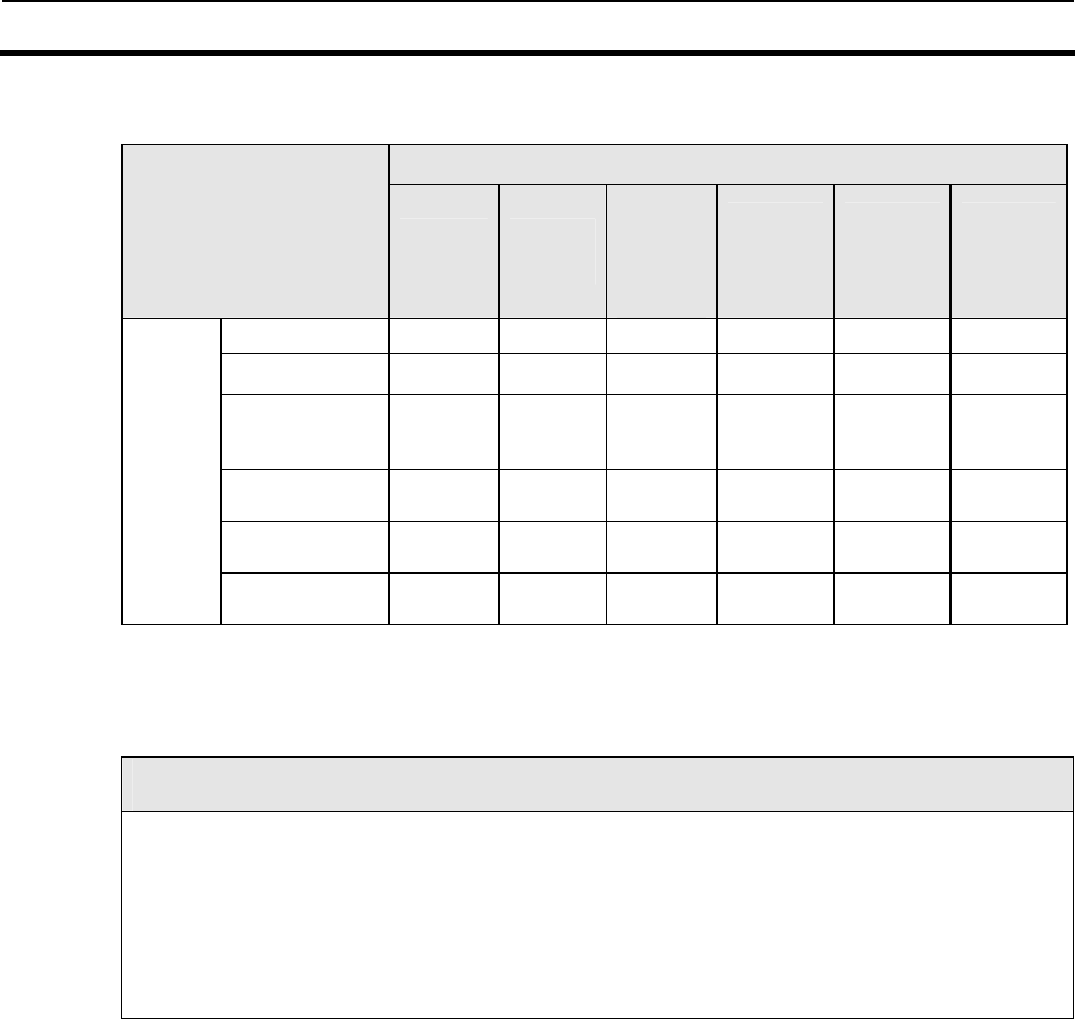
5-9 Command Connection: I.CODE1 Mode only 5-9
5-67
The Following Combinations of Command Connections Are Possible.
Command (1)
Read
(RD)
Write
(WT)
Memory
Calculati
on
(MK)
Memory
check
(MC)
Polling
read
(PR)
Polling
write
(PW)
Read(RD) 9 9 − − − −
Write(WT) 9 9 − − − −
Memory
Calculation
(MK) − 9 − − − −
Memory check
(MC) 9 − − − − −
Polling read
(PR) − − − − 9 9
Command
(2)
Polling write
(PW) − − − − 9 9
(: Command connection is possible;( : Command connection is not possible
Note
1. Communications method
The communications method specified using command (1) is given priority. Single Auto is specified for
Polling commands, and Single Trigger is specified for the memory check and memory calculations.
2. Polling process
If a Polling command is specified as command (1), the Reader/Writer will perform Polling.
3. Tag No. setting
The number of Tag No. setting made using command 1 is given priority.
6-1
SECTION 6
Startup and Full Operation
6-1 Error Types and Diagnostic Functions..............................................................6-2
6-2 Errors and Remedies..........................................................................................6-3
6-3 Maintenance and Inspection..............................................................................6-4
6-4 Troubleshooting..................................................................................................6-6
6-4-1 Check Flowchart...................................................................................................6-6
6-4-2 Check Items for Each Response Code ……………………………………… ……6-10
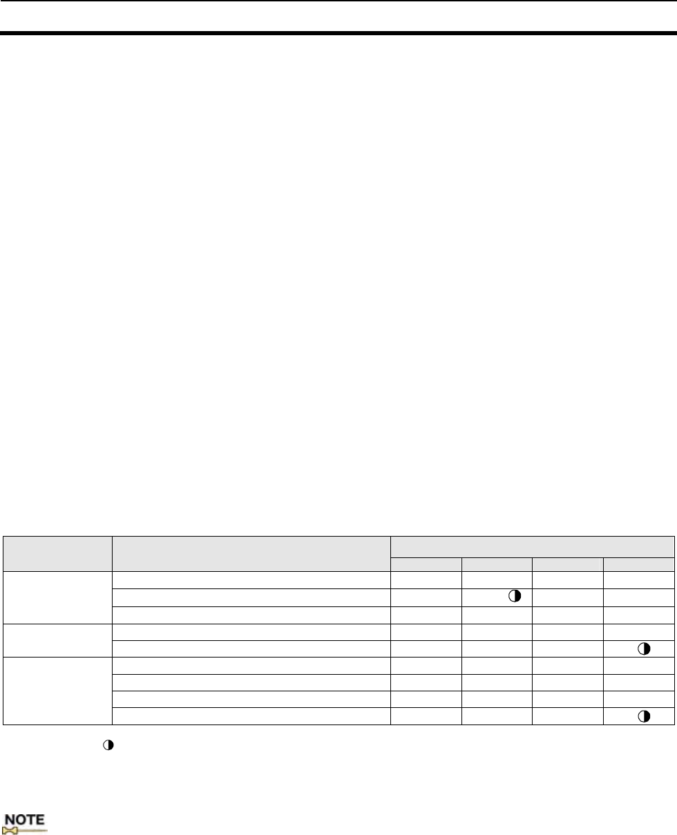
6-1 Error Types and Diagnostic Functions 6-1
6-2
The Reader/Writer performs a variety of self-diagnostic functions to reduce system downtime in case of an
error. The errors detected by the Reader/Writer are categorized into fatal errors and nonfatal errors.
Fatal Error If the Reader/Writer main unit or hardware fails, the CPU operation is interrupted and the
ERROR LED is turned on or flashed.
●CPU error
Detects the CPU operation error using the watch dog timer (W.D.T.)
●Memory error
Checks if data is read from or written onto the internal memory normally when the power is on.
Nonfatal error When an error occurs during communications between the Reader/Writer and the host, or the
antenna and Tag, the ERROR LED is turned on.
●Communication error
Checks for the errors in the communication processing sequence, frame, check code, and data at the execution of a command. The
error code corresponding to each error, is returned to the host as the response. (Error code:1□)
●Host communication error
Checks for the errors in the communication processing sequence of the command data, frame, check code, and data at the reception
of a command. The error code corresponding to each error is returned to the host as the response. (Error code:7□)
●System error
Checks that the command processing functions (EEPROM, communication circuit, etc.) are normal at the execution of a command.
The error code corresponding to each error is returned to the host as the response. If the error occurs repeatedly, the device needs
repair. (Error code:7C, 93)
●Set value error
Checks that set data concerning the operating environment on the EEPROM in the main unit is not corrupted.. Checks for errors at
power on, and if the error(s) are detected, operates in Online Mode with the factory default settings. The operating environment is
regained by setting the operating conditions once again.
■LED states in each condition
Indicator Item RUN COMM NORM ERROR
Awaiting command ○ ● ● ●
Communicating with Tag/ Offline mode ○ ○/ ● ●
Normal operation
Normal completion of communications with Tag ○ ● ○ ●
CPU error ● ● ● ○
Fatal error Memory error ● ● ●
Communications error ○ ● ● ○
Host communications error ○ ● ● ○
System error ○ ● ● ○
Nonfatal error
Setting error※ ○ ● ●
○:ON, ●:OFF, :Flashing
* The LED-lit state for the set value error is retained until the next command has been executed.
: During the communication with Tags in Online Mode, the COMM LED is lit in the software versions 1.20 and higher, or
flashes in versions 1.10 and lower.
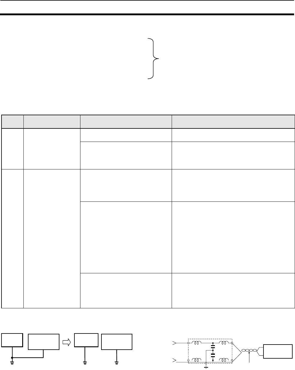
6-2 Errors and Remedies 6-2
6-3
The following are considered to be main causes of system breakdowns.
• Noise Interference.......................................Take appropriate countermeasures against noise.
• Failures in any of the external devices
• Failures in the Reader/Writer
• Failures in the Antenna
• Failures in the cable
• Failures in any of the Tags
• Others
■Noise Interference If the system malfunctions due to noise, refer to the following and take appropriate
countermeasures.
No. Circumstance of
failure Probably cause Remedy
1 An instantaneous voltage drop due
to inrush current to the heavy load. Increase the capacity of the power supply and
that of the power cable.
Occurs when a
heavy-duty motor,
transformer, or
capacitor is turned ON. Common mode noise caused by the
above cause. Provide the power through a 1-to1non-grounded
insulating transformer.
Independently ground the Reader/Writer at a
resistance less than 100 ohm.
2 Occurs irregularly
Noise on power line Provide the power through a 1-to-1
non-grounded insulating transformer or noise
filter.
Independently ground the Reader/Writer at a
resistance less than 100 ohm.
Noise propagated through space
1. When a power circuit, power
wire, or other signal wires for the
devices are located near the
antenna.
2. When a driving system such as
an inverter or motor is located
nearby.
3. When a power unit such as a
switching power source is located
nearby.
1. Place the power circuit, power wire, or other
signal wires for the devices as far away from the
antenna as possible.
Be sure to wire antenna cables separately from
other cables. Shield the power circuit, power
wire, or signal wires for other devices.
2. Be sure to ground the unit of the driving
system. Place the unit as far away from the
antenna as possible.
3. Be sure to ground the power unit. Place the
unit as far away from the antenna as possible.
More than one V720-series
Antenna When operating more than one V720-series
Antenna, provide a sufficient clearance between
the Antennas.
Refer to the instruction manual for your
antenna for details.
Improvement of grounding Remedy for power noise
Repairs are required.
Other
equipmen Reader/Writer
Reader/Writer
Other
equipment
Reader/Writer
Use twisted - pair wires.
Do not install them in parallel
with other power lines.
Line filter
+24 VDC
0 V
connecting to
a ground of
100 ohm or less

6-3 Maintenance and Inspection 6-3
6-4
The V720 Series must be inspected on a daily or regular basis so that the functions of the V720
Series can be used in good condition.
The V720 Series consists of semiconductors that last almost indefinitely. The following
malfunctions may, however, result due to the operating environment and conditions.
(1) Element deterioration due to overvoltage or overcurrent.
(2) Element deterioration due to continuous stress caused by high ambient temperature.
(3) Connector contact faults or insulation deterioration due to humidity and dust.
(4) Connector contact faults or element corrosion due to corrosive gas.
Item
No
. Item Detail Criteria Remarks
1 (1) Check that the supply voltage
fluctuation at the power supply
terminal block is within the
permissible range.
Supply voltage rating Voltage tester
Supply voltage fluctuation
(2) Check that there is no frequent
instantaneous power failures or
radical voltage drops.
Within permissible voltage
fluctuation range Power supply
analyzer
2 Environment
a. Ambient temperature
b. Ambient humidity
c. Vibration and shock
d. Dust
e. Corrosive gas
a. Check that the ambient
temperature is within the specified
range.
b. Check that the humidity is within
the specified range.
c. Check that no vibration or shock is
transmitted from any machines.
d. Check that the system is free of
adherence or accumulation of dust
or foreign matter.
e. Check that no metal part of the
system is discolored or corroded.
a. Check that the ambient
temperature is within the
specified range.
b. Check that the humidity is
within the specified range.
c. Check that the ambient
temperature and humidity
are within the specified
ranges.
d. Check that there is no dust
or foreign matter.
e. Check that there is no
discoloration or corrosion.
Maximum and
minimum
thermometer
Hygrometer
3 Panel condition
a. Ventilation
b. Packing for any
enclosed construction
a. Check that the system is ventilated
properly with natural ventilation,
forced ventilation, or cooling air.
b. Check that the packing is properly
attached with no damage.
a. The interior temperature
must be within a range
between -10°C and 50°C
with proper ventilation.
b. The packing has no damage.
―
4 I/O power supply
a. Voltage fluctuation
b. Ripple
Check on the I/O terminal block that the
voltage fluctuation and ripple are within
the permissible ranges.
The voltage fluctuation and
ripple must be within the
specified range.
Voltage tester
Oscilloscope
(1) Check that each device is securely
mounted. There must be no loose screws. ―
(2) Check that each connector is
securely connected. Each connector is locked or
securely tightened with screws ―
(3) Check that no screw of the
terminal block is loosened. There must be no loose screws. ―
(4) Check that no wire is broken or
nearly broken. There must be no wire that is
broken or nearly broken. ―
(5) Check that the distance between
the Tag and Antenna is within the
specified range.
The distance between the Tag
and Antenna must be within
the specified range. ―
5 Mounting condition
(6) Check that the GR terminal is
grounded. The terminal must be grounded
to a resistance of 100 ohm or
less. ―
6-4 Troubleshooting 6-4
6-5
6-4-1 Check Flowchart
Use the following main check flowchart to determine the cause of the error.
■Main Check Flowchart
メインチェックフロー
リーダライタは
コマンド待ち状態
ですか?
上位通信は
正常ですか?
タグとの交信は
正常ですか?
YES
YES
YES
NO
NO
NO
「システム接続チェックフロー」へ
「上位通信チェックフロー」へ
「交信チェックフロー」へ
リーダライタの
故障が考えられます
外部環境は
正常ですか?
YES
NO 「外部環境チェックフロー」へ
Is the ambient environment
normal?
Go to Host
communications
Check Flowchart
Go to Ambient
Environment Check
Flowchart
Go to Communications
Check Flowchart
Go to System
connection Check
Flowchart
Is the system
connection normal?
Is the host communications
normally?
Is the communications
with tag normal?
Main Check Flowchart
Replace
he Reader/Writer.
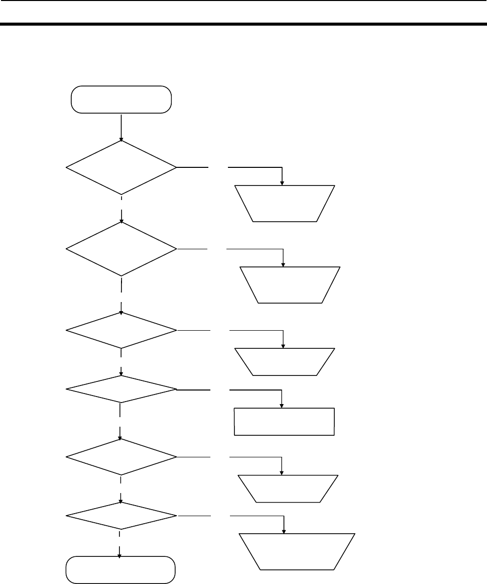
6-4 Troubleshooting 6-4
6-6
■System connections check flowchart
Start
A
re the connectors and
cables connected
properly?
Connect the
connector/cable
p
ro
p
erl
y
.
Is the specified
voltage applied or
current supplied?
Is Reset input ON?
Apply the specified
voltage or supply the
s
p
ecified current.
Turn OFF Reset
it
Is the RUN LED lit?
Is COMM LED
flashing?
The Reader/Writer
may have failed.
Is ERR LED
flashing?
Cancel the Offline
setting.
Set the Reader/Writer setting
values again and write using
EW Command.
OK
YES
YES
YES
YES
YES
NO
NO
NO
NO
NO
NO
NO
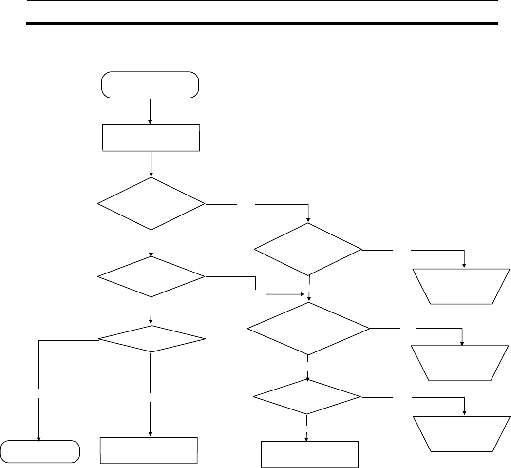
6-4 Troubleshooting 6-4
6-7
■Host communications Check Flowchart
Start
Specify the correct
communication settings
and node ID.
Modify the host program
or replace the host
device.
Error response 7C
Is the host operating
normally?
Issue TS Command
from the host.
OK
The lit NORML LED
or ERR LED is
turned off.
The response has
been received.
YES
YES
YES
NO
NO
YES
A
re the communication
conditions, command
frame, node ID OK?
A
re the connector’s pin
assignments for the
communication cables OK?
Correct the pin
assignments of the
connectors.
The Reader/Writer
may have failed.
Refer to section 6-4-2 Check
Items for Each Response Code.
NO
YES
NO
YES
NO
NO
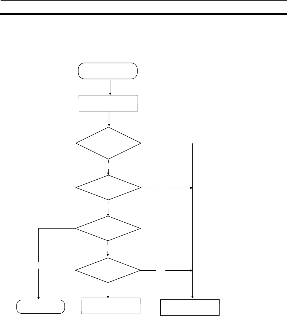
6-4 Troubleshooting 6-4
6-8
■Communications Check Flowchart
Start
Issue Write Command in
Single Trigger mode.
The lit NORML LED
or ERR LED is
turned off.
The response has
been received.
Is the response
normal?
Response Code 7C
The Reader/Writer
may have failed.
Refer to section 6-4-2 Check
Items for Each Response Code.
OK
YES
YES
NO
NO
YES
NO
NO
YES
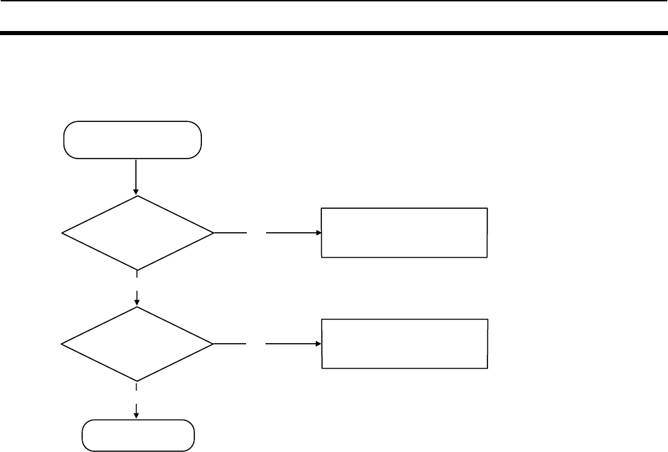
6-4 Troubleshooting 6-4
6-9
■External Environment Check Flowchart
Refer to section 6-3
Maintenance and Inspection.
Refer to section 6-2 Errors
and Remedies.
Start
I
s
th
e am
bi
en
t
noise OK?
Are the operating
conditions working
well?
OK
YES
YES
NO
NO

6-4 Troubleshooting 6-4
6-10
6-4-2 Check Items for Each Response Code
Response Code Primary check items
(Nonresponding
state) ・Are the communication conditions set for the host and the Reader/Writer matched?
Transmission rate, data length, stop bit length, parity (even, odd, none)
・Is the control code (STX/ETX) transmitted properly?
・Are the command node No. and Reader/Writer node No. setting matched?
・Is the Reader/Writer set to Offline mode?
・Is the command issued by the Reader/Writer executable in the state?
Offline mode: Commands are not accepted.
Communication with the Tag in progress: Commands are not accepted.
FIFO mode: Only FIFO Access command is accepted.
Select state: Only Tag Designation command is accepted.
*Stop Command (ST) and Reset Command (XZ) are always executable.
・Is the command issued during the initialization (approximately 2.5 seconds) that follows
power ON or Reset Command execution?
10
11
12
・Are the communication conditions set for the host and the Reader/Writer matched?
Transmission rate, data length, stop bit length, parity (even, odd, none)
・Is there a noise source near the communication cables?
13 ・Is the added BCC correct?
Calculation method, Format (Binary,1byte)
14 ・Is data for each command field correct?
Communication method specified (Types, combination with the commands), specified data,
Tag types, page, written data
・Is the command executable with the Reader/Writer’s chip operating mode (I.CODE1/ISO)
settings?
・Is the simplified number already assigned using Tag designation command? [I.CODE1
Mode]
18 ・Is the command to be issued correct?
・Is the control code (STX/ETX) transmitted correctly?
70 ・Aren’t there multiple Tags present in the communication area? [In Single Access mode]
・Is there any antennas other than the one communicating, nearby?
・Are there any devices or cables that could be a source of noise nearby?
・Is the Tag in the stable communication area?
・Does the Tag stay for a short time in the communication area? (Is it moving fast enough?)
・Is the specified page within the Tag’s memory range?
・Does the Reader/Writer support the Tag?
71 ・Is the Tag re-written exceeding its rewrite cycle?
・Is the write target page locked? [In ICODE1 Mode]
・Does the Reader/Writer support the Tag?
72 ・Is the communication distance between the antenna and Tag appropriate?
・Are there multiple Tags present in the communication area?
・Are chip operating mode and the type of Tag used matched?
・Does the Reader/Writer support the Tag?
79 ・Is the specified page within the Tag’s memory range? [ISO mode - I.CODE SLI]
・Is the write target page locked? [ISO Mode - I.CODE SLI]
7A ・Is the specified page within the Tag’s memory range? [ISO mode]
7C ・If this occurs continuously, the Reader/Writer may fail.
7E ・Is the specified page locked? [ISO Mode]
(IC) ・The command code for the command is incorrect.
7-1
SECTION 7
Reference Data
7-1 Turn Around Time and Communication Time........................................................7-2
7-1-1 Communication time in I.CODE1 mode...................................................................7-2
7-1-2 ISO mode - Communication time of I.CODE SLI chip............................................7-4
7-1-3 Turn Around Time (TAT) Calculation Method.........................................................7-6
7-2 Calculating the speed of the Tag.............................................................................7-7
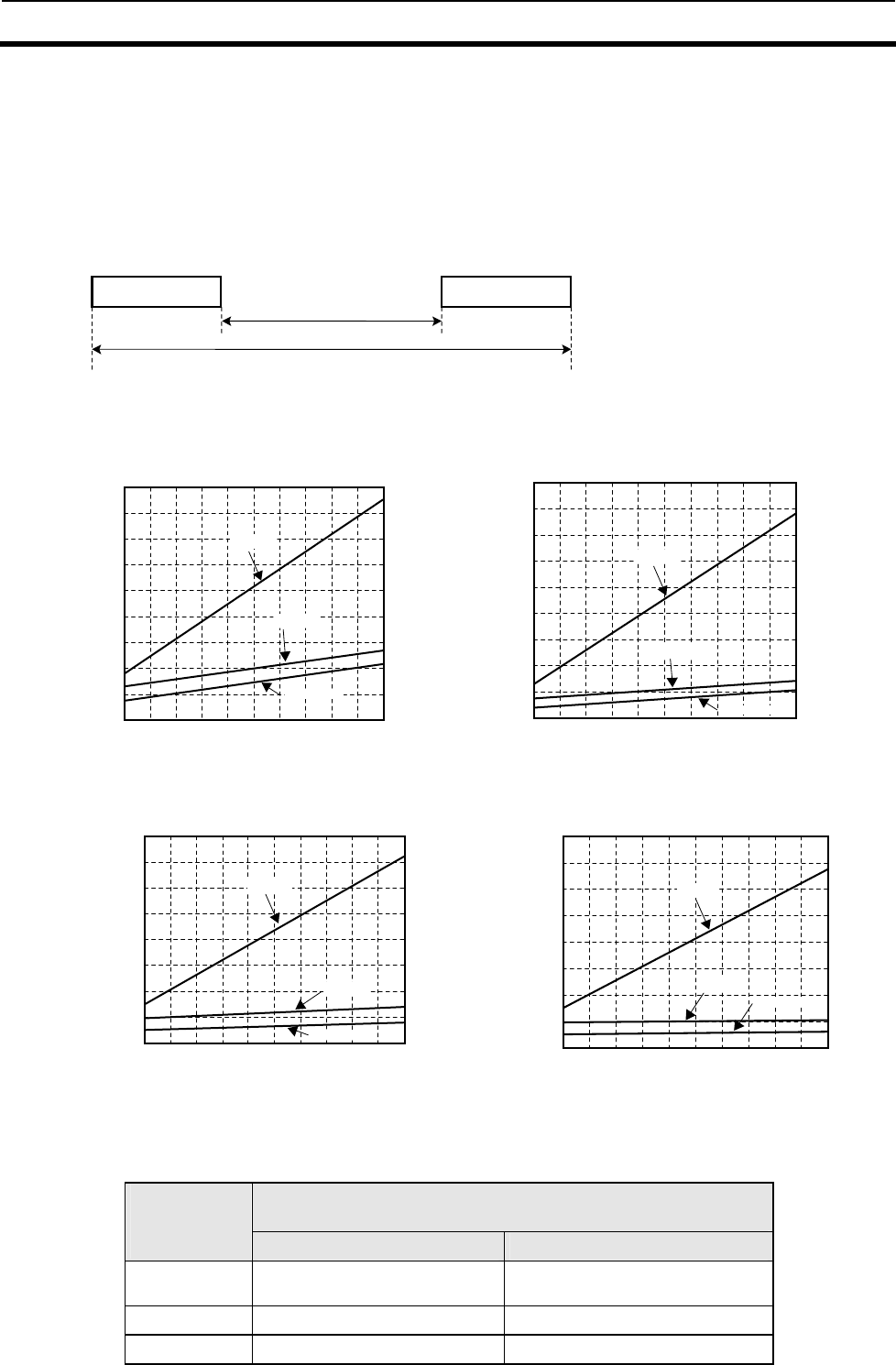
7-1 Turn Around Time and Communication Time 7-1
7-2
In the V720-series Reader/Writer, actual communications with a Tag are performed by reading
or writing four-byte data per page.
• The following chart specifies the TAT (turn-around time) and actual communications time.
• The actual communications time in the following chart is the time required for
communications between the Antenna and Tag, not including communications with the host.
Use this for calculating the speed of the Tag for the execution of auto commands.
Ex.)
7-1-1 Communication time in I.CODE1 mode
(1)Communication time in Single Access Mode
●Fast mode
●Standard Mode
Calculation Formula:I.CODE1 Chip
Actual communications time (msec) N: Number of pages
processed
Communicatio
n time setting Fast mode Standard Mode
Special
reading T = 1.3N + 6.2 T = 1.3N + 43.4
Read T = 1.3N + 12.7 T = 1.3N + 91.6
Write T = 13N +13.5 T = 54.2N + 90.0
Command Response
A
ctual
communications time
T
A
T
1
0
2 0
4
0
6 0
8
0
1
0
0
1 2 0
1
4
0
1
8
0
T
A
T
(
m
s
)
Number of pages processed
2 3 4 5 6 7 8 9 10 11
1 6 0
Writing
Reading
Special reading
1
0
20
40
60
80
100
120
140
180
A
ctual
communicat
ions time
(ms)
Number of pages processed
2 3 4 5 6 7 8 9 1
0 1
1
160
Writing
Reading
Special reading
1
0
1 0 0
2 0 0
3
0
0
4 0 0
5 0 0
6
0
0
7
0
0
8 0 0
Number of pages processed
2 3 4 5 6 7 8 9 10 11
Writing
Reading
Special reading
TAT(ms)
1
0
100
200
300
400
500
600
700
800
A
ctual
communicati
ons time
(ms)
Number of pages processed
23456 7 8 9 1
0 11
Writing
Reading
Special reading
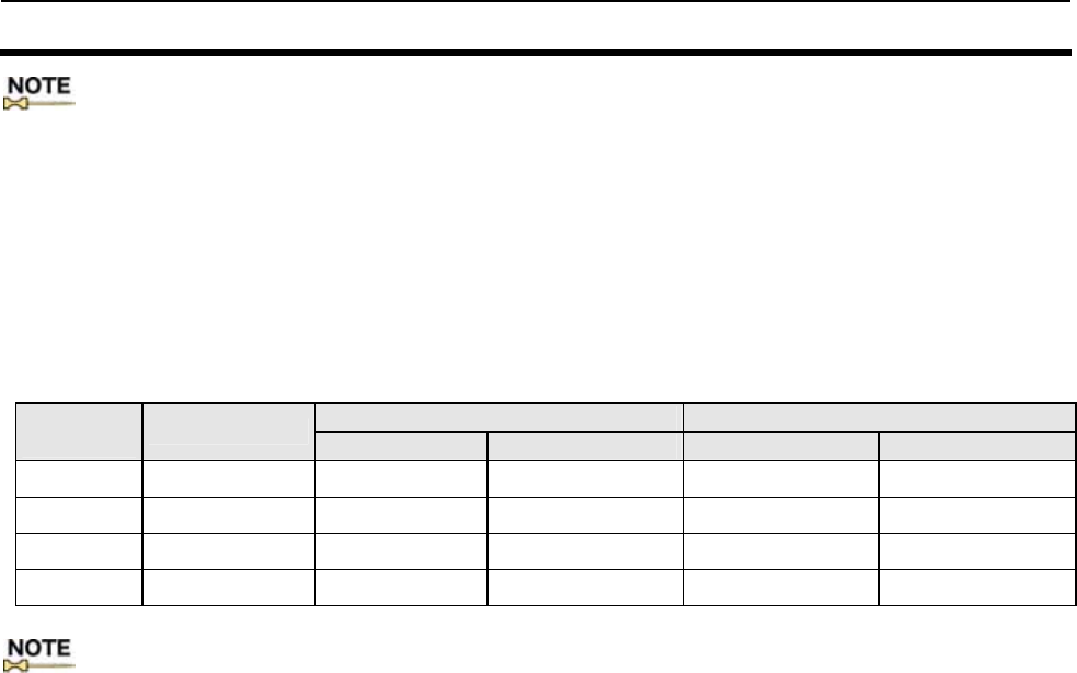
7-1 Turn Around Time and Communication Time 7-1
7-3
: ・ The provided TAT graph data shows an example in which the V720S-BC5D4A Controller is used with the
following communications specifications for host communications: Data is continuously sent with no
space between characters, at a baud rate of 38,400 bps, in a data length of 7 bits with 1 start bit, 2 stop
bits and even parity . The number of bytes in case ASCII are specified as the data code.
・The transmission rate of the Tag is set in Fast Mode as factory default.
(2)Communication time in
Multiple modes:
The communication time when the commands with multiple access options
are used varies depending on operating conditions. Those conditions
include the number of bytes, as well as the number of Tags in the
communication area. The mean values in consideration of these conditions
are shown in the table below.
Example of Multiple Access communication time: I.CODE1 Chip (msec)
2 pages (8 bytes) Read 2 pages (8 bytes) Write
Number of
Tags Tag No.setting Fast Mode Standard Mode Fast Mode Standard Mode
2 1 144 560 190 715
4 2 301 917 378 1139
8 3 644 1659 784 2016
16 4 1391 3239 1656 3867
:The transmission rate of the Tag is set in Fast Mode as factory default.
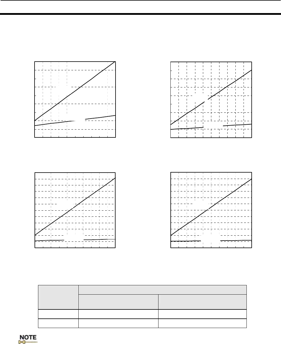
7-1 Turn Around Time and Communication Time 7-1
7-4
7-1-2 ISO mode - Communication time of I.CODE SLI chip
(1)Communication time in Single Access Mode
● Fast mode
●Standard mode
Calculation Formula:I.CODE SLI Chip
Actual communications time (msec) N: Number of pages processed
Communicatio
n time setting Fast mode Standard Mode
Read T = 1.3N + 18.0 T = 1.3N +104
Write T = 13N +18.0 T = 90N + 105
: ・ The provided TAT graph data shows an example in which the V720S-BC5D4 Controller is used
with the following communications specifications for host communications: Data is continuously
sent with no space between characters, at a baud rate of 38,400 bps, in a data length of 7 bits with
1 start bit, 2 stop bits and even parity . The number of bytes in case ASCII are specified as the
data code.
・ The transmission rate of the Tag is set in Fast Mode as factory default.
(ms)
リード
ライト
0
20
40
60
80
100
120
140
160
180
1234567891011
処理ページ数
交信時間
(ms)
リード
ライト
0
20
40
60
80
100
120
140
160
180
1234567891011
処理ページ数
TAT
(ms)
リード
ライト
0
100
200
300
400
500
600
700
800
900
1000
1100
1200
1234567891011
処理ページ数
交信時間
(ms)
リード
ライト
0
100
200
300
400
500
600
700
800
900
1000
1100
1200
1234567891011
処理ページ数
TAT
writing
Reading
writing
Reading
Reading
Reading
writing
writing
Actual
communica
tions time
(ms)
Actual
communica
tions time
(ms)
Number of pages proceeds
Number of pages proceeds
Number of pages proceeds
Number of pages proceeds
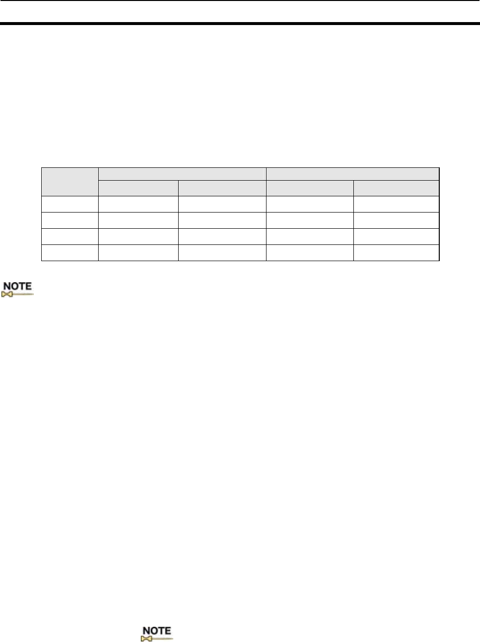
7-1 Turn Around Time and Communication Time 7-1
7-5
(2)Communication time in
Multiple modes:
The communication time when the commands with multiple access options
are used varies depending on operating conditions. Those conditions
include the number of bytes, as well as the number of Tags in the
communication area. The mean values in consideration of these conditions
are shown in the table below.
:The transmission rate of the Tag is set in Fast Mode as factory default.
7-1-3 Turn Around Time (TAT) Calculation Method
Calculation of TAT TAT can be calculated by adding the host communications time to the
actual communications time. The host communications time varies
depending on the communications settings and the codes that you specify.
Example of calculation: when operating in Single Access Mode and Trigger
Mode to read 1 page (4 bytes) data
■Code-specified in ASCII:
The total number of characters is 29, i.e., 15 characters in the command
part and 14 characters in the response part. From this, the host
communications time would be 29 * 11 bits /38400(bps) * 1000 = 8.3 (ms).
The communications time would be14 ms for Fast Mode and 92.9 ms for
Standard Mode. TAT, therefore, would be 8.3 + 14 = 22.3 ms for Fast Mode
and 8.3 + 92.9 = 101.2 ms for Standard Mode.
■Code-specified in HEX:
The total number of characters is 33, i.e., 15 characters in the command
part and 18 characters in the response part. From this, the host
communications time would be 33 * 11 bits /38400(bps) * 1000 = 9.5 (ms).
The communications time would be14 ms for Fast Mode and 92.9 ms for
Standard Mode. TAT, therefore, would be 9.4 + 14 = 23.5 ms for Fast Mode
and 9.4 + 92.9 = 102.4 ms for Standard Mode.
:
・ The provided TAT graph data shows an example in which the V720S-BC5D4
Controller is used with the following communications specifications for host
communications: The data is continuously sent with no space between
characters, at a baud rate of 38,400 bps, in a data length of 7 bits with 1 start bit,
2 stop bits and even parity.
Example of Multiple Access communication
time: I.CODE SLI Chip (msec)
2 pages (8 bytes) to read (ms) 2 pages (8 bytes) to write (ms)
Number of
Tags Fast mode Standard Mode Fast mode Standard Mode
2 115 749 161 1103
4 192 1300 285 2009
8 338 2354 525 3773
16 639 4511 1013 7349
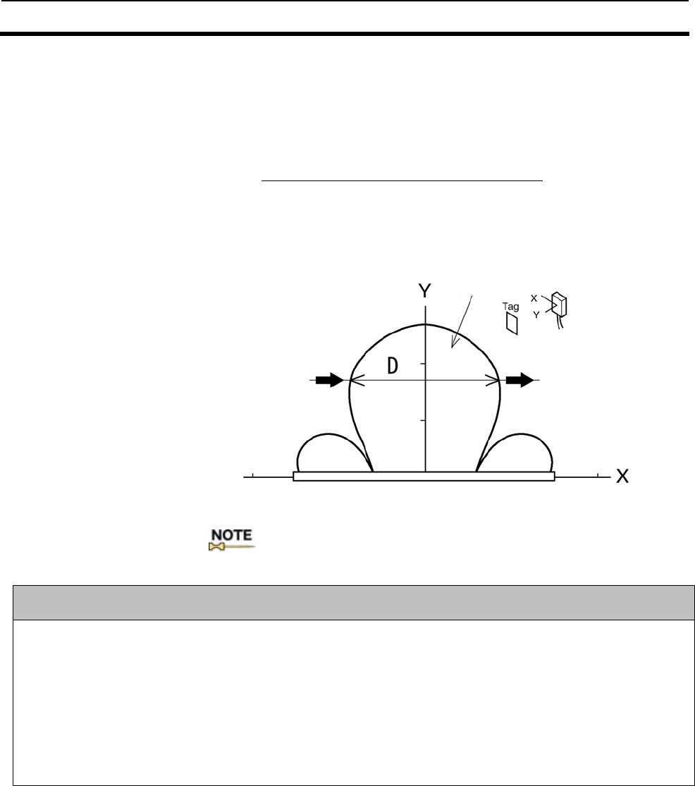
7-2 Calculating the speed of the Tag 7-2
7-6
When communicating with a Tag in motion, select Auto or Repeat for the
communications method.
The maximum speed at which the Tag can travel can be obtained easily,
using the formula below.
D (travel distance in communications
area)
Max. traveling speed = T (communications time) x Safety factor (0.5)
Calculate D from the communications area drawing between the Antenna
and the Tag or from the actual measurement.
:The formula above is for communications with one Tag. Be sure to check
the traveling speed of multiple Tags in advance.
Notes on the passing speed evaluation:
1) As a precaution to ensure minimal noise, the Reader/Writer performs retransmission tests in the event of a
communication error between the Tag and antenna. Since the transmission time is dependent on the noise
conditions in each environment, a transmission test using the actual device must be conducted in advance. The
calculation formula for the communication time does not assume retransmission.
2) The calculation formula above assumes the communication with one Tag. The communication with multiple
Tags in transit must be tested in advance. It cannot be calculated with the formula. The anti-collision
algorithm for the access to multiple Tags is derived from a probability theory; the communication time will
fluctuate depending on how the collisions occur, which means enough time must be allowed for the
communications.
Communications
area
Direction of travel
8-1
SECTION 8
Appendix
Appendix 1 Accessories ....................................................................................................8-2
Appendix 2 JIS8 Code Table (ASCII Code Table) ...........................................................8-3
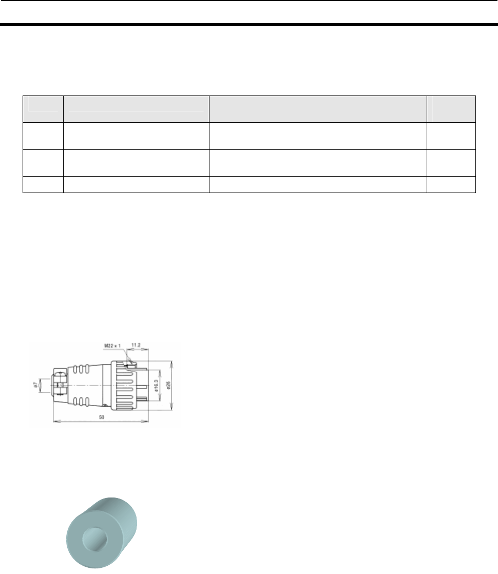
A
ppendix 1 Accessories
8-2
Appendix 1 Accessories
No. Name Model Quantit
y
1) Mounting plate (already
attached to the Reader/Writer) - 2
2) I/O connector plug NJW-2010-PM10 from Nanaboshi Electric Mfg.
Co., Ltd. 1
3) Ferrite core ZCAT3035-1330 from TDK 1
<Description>
1) Mounting plate (already attached to the Reader/Writer)
Secure the Reader/Writer by using four M6 screws to .
2) I/O connector plug
Use the I/O connector plug under the following conditions:
Outer diameter of the cable to be used φ8.0 to φ11.0.
For detail information for assemble, refer to 4-6-3-1 Assembly of Host Communications Connector and
I/O Connector.
3) Ferrite core
Clamp the ferrite core around the wire near the 100VAC of power supply (S82K-03024 from OMRON
recommended). For attachment method, refer to 4-6-1 “Power Supply and Grounding Wires”.
<Contact>
Nanaboshi Electric Mfg. Co., Ltd.
49-15, Kamitakada 1-chome, Nakano-ku,
Tokyo 164-0022
TEL: 03-3386-3181
FAX: 03-3388-1561
<Contact>
TDK. Corporation
1-13-1, Nihonbashi, Chuo-ku,
Tokyo, 103-8272
TEL: 03-3278-5111
A
ppendix 2 JIS8 Code Table (ASCII Code Table)
8-3
High Order
Low Order b8 - b5 0000 0001 0010 0011 0100 0101 0110 0111
b4 - b1 Colum
Row 0 1 2 3 4 5 6 7
0000 0 NUL TC7(DLE) (SP) 0 @ P ` p
0001 1 TC1(SOH) DC1 ! 1 A Q a q
0010 2 TC2(STX) DC2 " 2 B R b r
0011 3 TC3(ETX) DC3 # 3 C S c s
0100 4 TC4(EOT) DC4 $ 4 D T d t
0101 5 TC5(NEQ
) TC8(NAK
) % 5 E U e
0110 6 TC6(ACK) TC9(SYN) & 6 F V f v
0111 7 BEL TC10(ETB
) ' 7 G W g w
1000 8 FE0(BS) CAN ( 8 H X h x
1001 9 FE1(HT) EM ) 9 I Y i y
1010 10 FE2(LF) SUB * : J Z j z
1011 11 FE3(VT) ESC + ; K [ k {
1100 12 FE4(FF) IS4(FS) , < L \ l |
1101 13 FE5(CR) IS3(GS) - = M ] m }
1110 14 S0 IS2(RS) . > N ^ n ~
1111 15 S1 IS1(US) / ? O _ o DEL
:The ASCII code character for the fifth row, line 12 is “ “.

Revision History
A manual revision code appears as a suffix to the catalog number on the front cover of the manual.
SRFM- 002A
Revision code
The following table outlines the changes made to the manual during each revision. Page numbers refer to the
previous version.
Revision code Date Revised content
1 September, 2006 First Edition (New issued for Rohs Directive)

Manual No. SRFM-005A Note: Specifications subject to change without notice. Printed in Japan
Authorized Distributor:
Up-to-date information on RFID Systems can be accessed at OMRON's web site at
http://www.omronrfid.com/
OMRON CORPORATION
RFID BUSINESS DEVELOPMENT DEPARTMENT
14th Fl., Gate City Osaki West Tower
1-11-1 Osaki, Shinagawa-ku,
Tokyo 141-0032 Japan
Tel: (81)3-5435-2016/Fax: (81)3-5435-2017
Regional Headquarters
OMRON ELECTRONICS LLC
1920 Thoreau Drive Suite 165 Schaumburg, IL 60173
U.S.A.
Tel: (1)847-303-0780/Fax: (1)847-925-1260
OMRON EUROPE B.V.
Wegalaan 57, NL-2132 JD Hoofddorp
The Netherlands
Tel: (31)23-568-1200/Fax: (31)23-568-1222
OMRON ASIA PACIFIC PTE. LTD.
83 Clemenceau Avenue,
#11-01, UE Square,
239920 Singapore
Tel: (65)835-3011/Fax: (65)835-2711
OMCC: OMRON (CHINA) CO., LTD.
Rm.302, AZIA Center, 1233 Lujiazui Ring Road
Pudong New Area, Shanghai 200120, PRC.
Tel: (86)21-5888-1666
Fax: (86)21-58888-7633/7933