Omron RFID Business Development Department V750-BA50C04 RFID Tag Reader User Manual
Omron Corporation, RFID Business Development Department RFID Tag Reader
UserManual.wiki
>
Omron RFID Business Development Department
>
V750 BA50C04 User Manual
user manaual
Navigation menu
Upload a User Manual
Namespaces
Wiki Guide
HTML
PDF
Info
Views
User Manual
Discussion / Help
Navigation
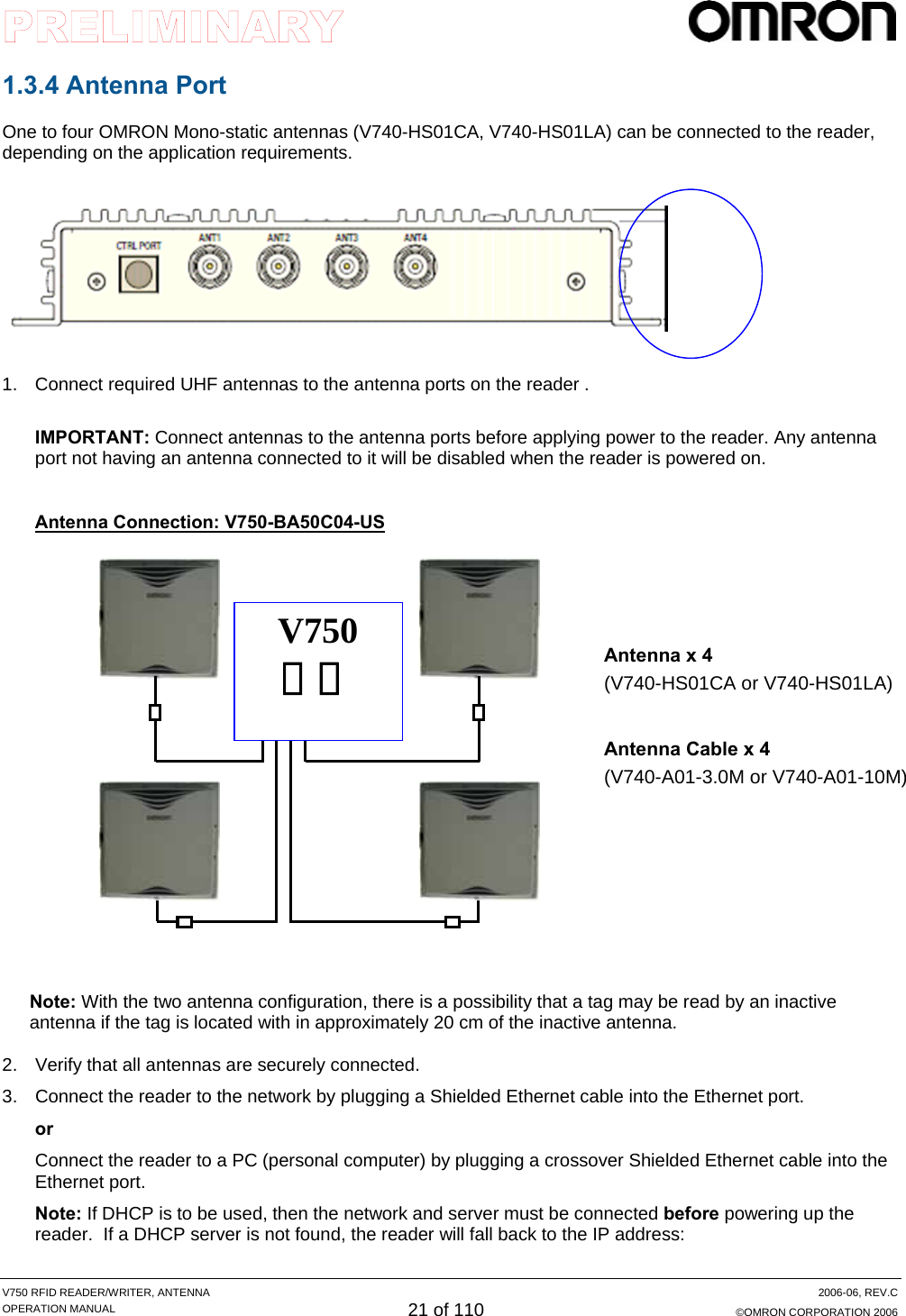
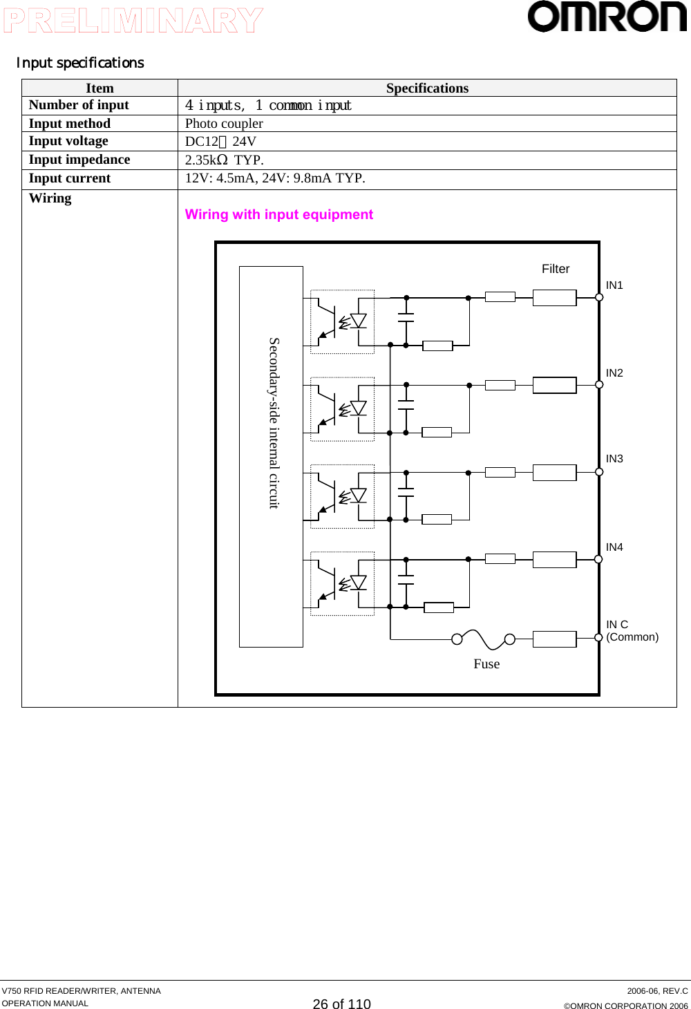
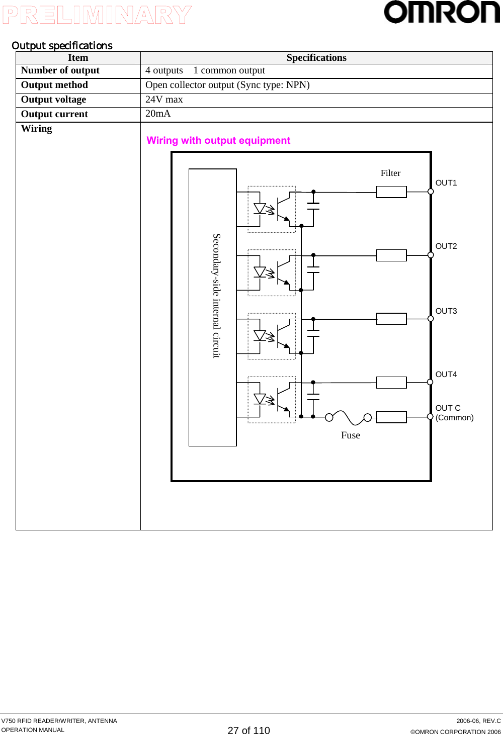
![V750 RFID READER/WRITER, ANTENNA 2006-06, REV.C OPERATION MANUAL 25 of 110 ©OMRON CORPORATION 2006 1.3.6 I/O Interface As an input/ output port, the R/W contains a terminal block of which male connector is removable and attachable with screws. Terminal block connector: MC1.5/10-SFT-3.81 (PHOENIX CONTACT GmbH & Co.KG) Pin assignment Pin No Name I/O Description 1 OUT 1 OUT Output 1 2 OUT 2 OUT Output 2 3 OUT 3 OUT Output 3 4 OUT 4 OUT Output 4 5 OUT C - Output common 6 IN 1 IN Input 1 7 IN 2 IN Input 2 8 IN 3 IN Input 3 9 IN 4 IN Input 4 10 IN C - Input common [配線手順] (必要工具) ①ケーブルをコネクタに結線 ※ マイナスドライバ ・ケーブル固定ネジを緩めて(左回し)、ケーブルを奥まで挿入する。 ・ケーブル固定ネジを閉めて(右回し) ②コネクタをリーダライタ本体に取付け ③取り付けネジ2本で固定 マイナスドライバ ※ケーブルのコネクタへの結線は、必ずコネクタの本体取付け前に行ってください。 6 10 9 8 7 5 4 3 2 1Input terminal Output terminal Mounting screw Mounting screw ケーブル固定ネジ x 8](https://usermanual.wiki/Omron-RFID-Business-Development-Department/V750-BA50C04/User-Guide-714521-Page-25.png)

![V750 RFID READER/WRITER, ANTENNA 2006-06, REV.C OPERATION MANUAL 47 of 110 ©OMRON CORPORATION 2006 2.4 Tag Fundamentals Tag Memory Structure Protocols and the tag memory structures supported by the V750 reader are described below. For additional information regarding tag operation, refer to each tag specification. GEN2 Tags GEN2 tags have four memory banks. Kill Password and Access Password are stored in bank 00 (Reserved Area), EPC code is in bank 01 (EPC Area), Tag Identification Memory data that is read only is in bank 10 (TID Area). User data is in bank 11 (User Area). For the detailed information refer each tag's specification. Bank block number Bit Contents 0 00-0F Kill Password [31:16] 1 10-1F Kill Password [15:0] 2 20-2F Access Password [31:16] 3 30-3F Access Password [15:0] 00 (Reserved Area) ... ... ... 0 00-0F CRC-16 1 10-1F Protocol-Control Bits (PC) 2 20-2F EPC[95:80] 3 30-3F EPC[79:64] 4 40-4F EPC[63:48] 5 50-5F EPC[47:32] 6 60-6F EPC[31:16] 7 70-7F EPC[15:0] 01 (EPC Area) ... ... ... 0 00-0F 1 10-1F Tag Identification Memory data (read only) 10 (TID Area) ... ... ... 0 00-0F User data 1 10-1F 2 20-2F 11 (User Area) ... ... ...](https://usermanual.wiki/Omron-RFID-Business-Development-Department/V750-BA50C04/User-Guide-714521-Page-47.png)
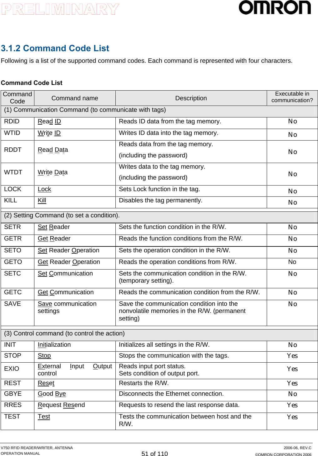
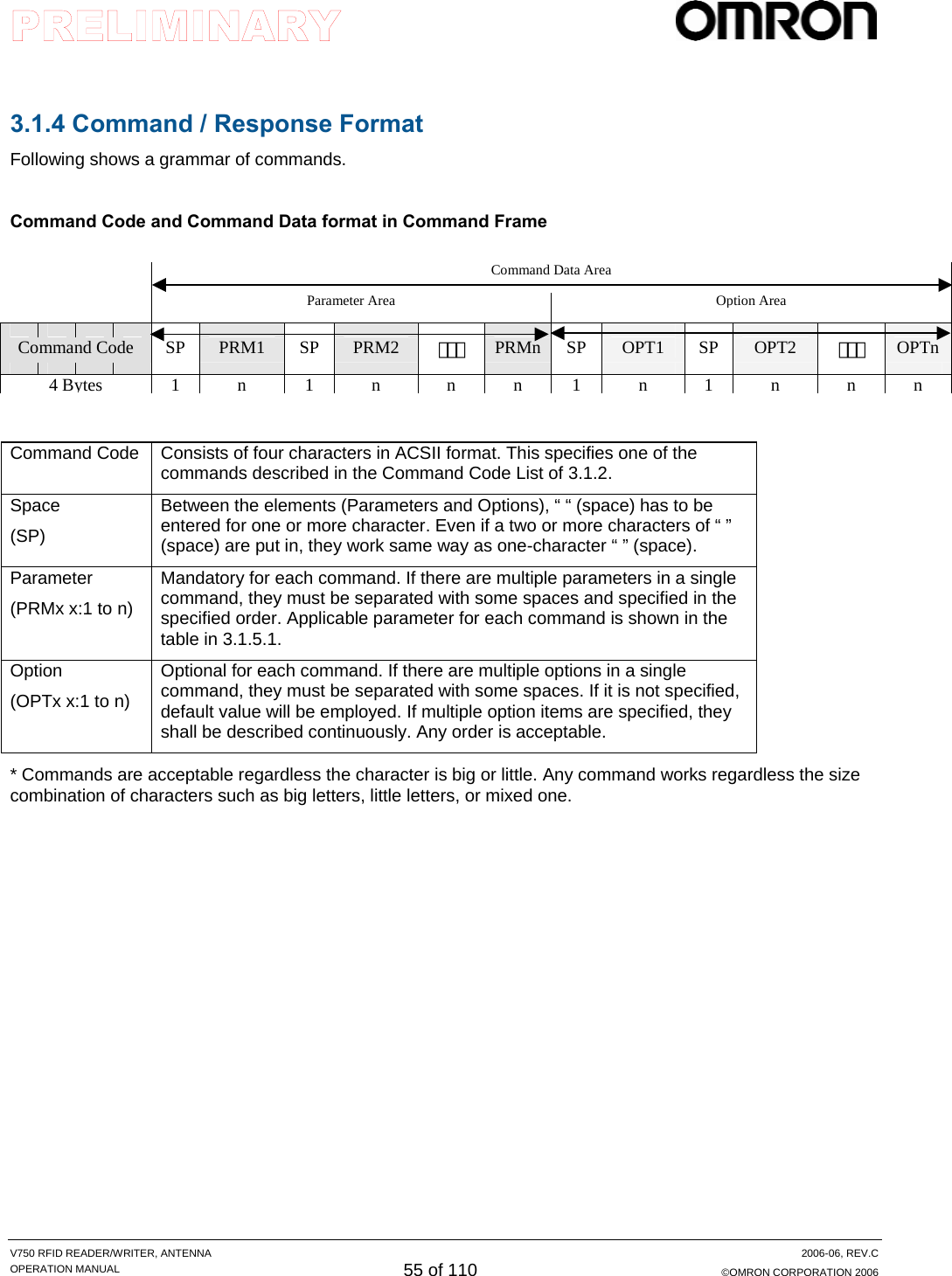
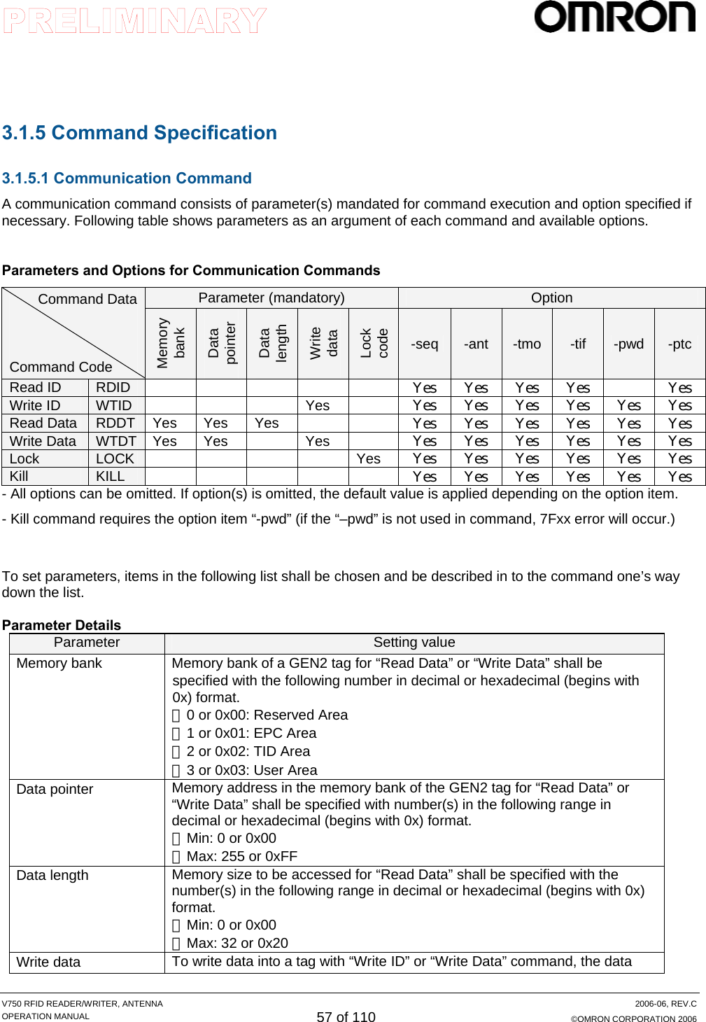
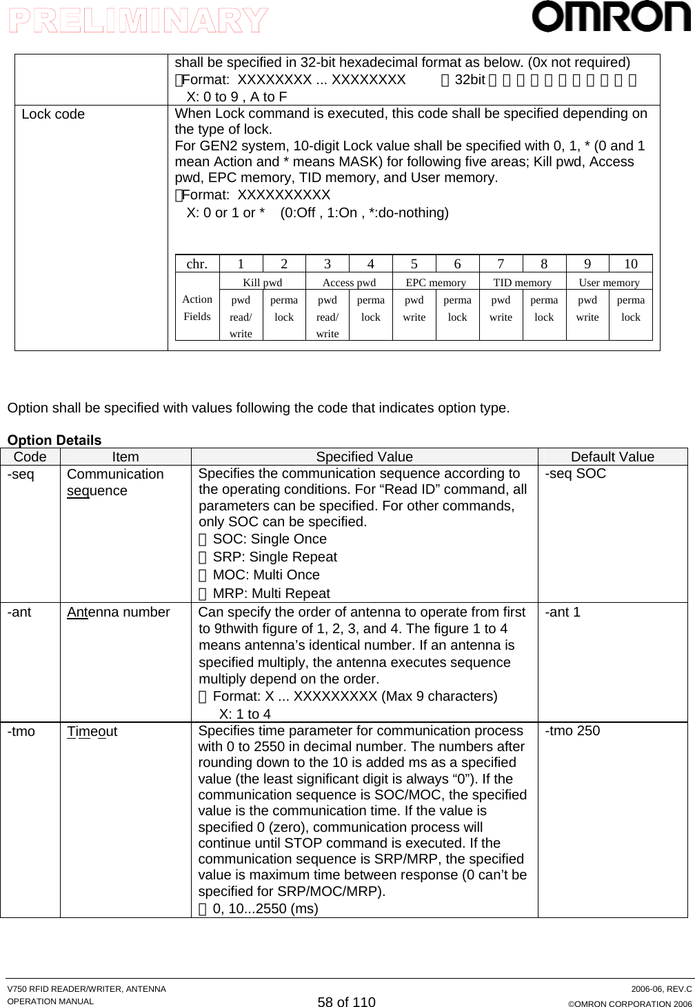
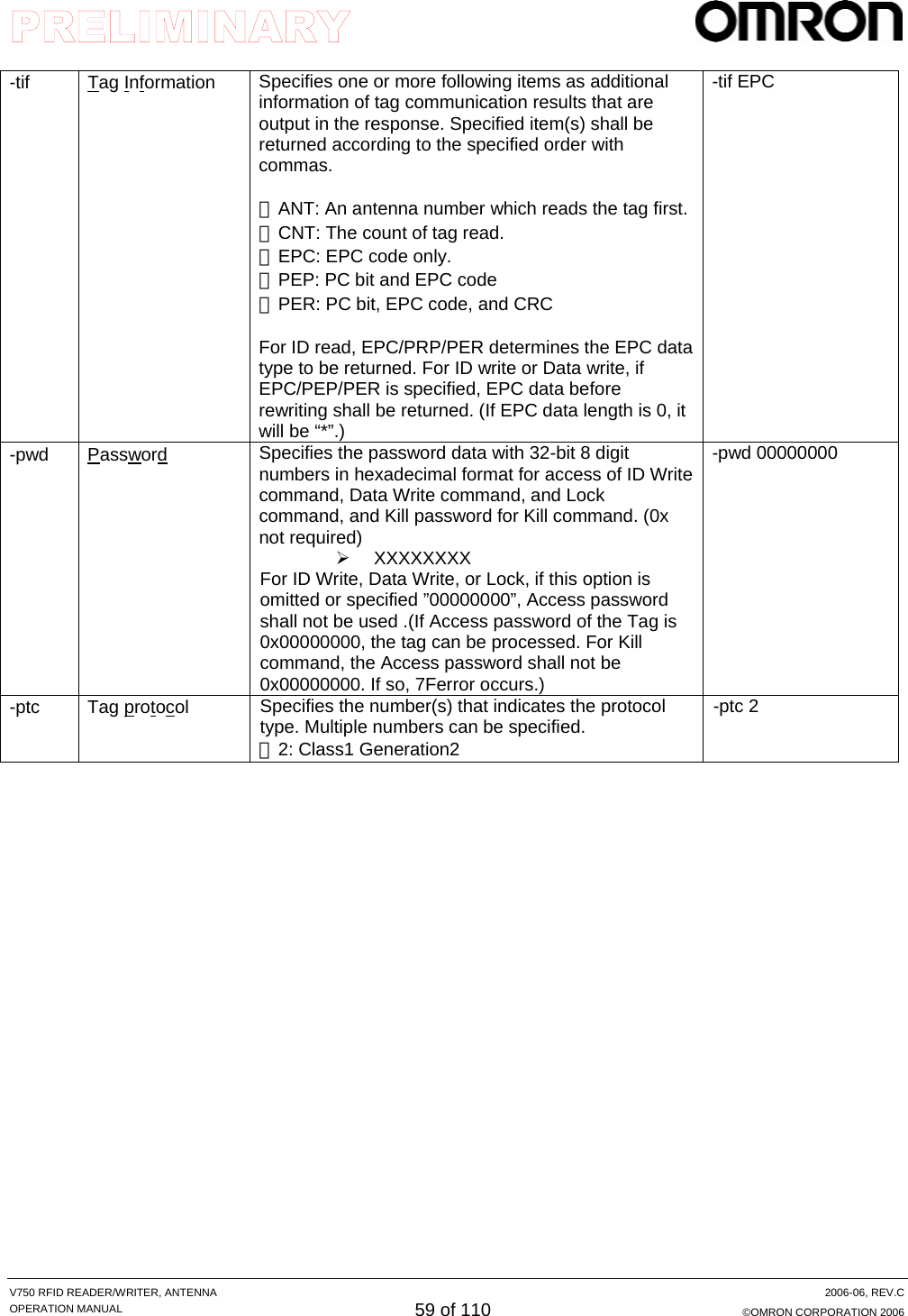
![V750 RFID READER/WRITER, ANTENNA 2006-06, REV.C OPERATION MANUAL 48 of 110 ©OMRON CORPORATION 2006 3. Command Line Interface About this Guide This chapter lays the groundwork for the communication protocol between client software running on a remote computer and the V750 reader. 3.1 Command Interface 3.1.1 Command / Response Frame Structure Ethernet and RS-232C has almost same command structure for command line I/F. Command frame has a Command Code area to control the R/W and Command Data area that is used with Command Code. Terminator that indicates the end of the frame is [LF]. RS-232C requires a start code [SOH], check data, and [CR]. The start code shall be at the beginning of the frame, and the check data and the [CR] shall be immediately before terminator ([LF]). Command frame for Ethernet Command frame for RS-232C Contents in command frame Contents Description Ethernet required? RS-232Crequired?Start code [SOH,0x01] Indicates the beginning of the frame with SOH,0x01. No Yes Command code Specifies the command the Reader executes. Yes Yes Command data Specifies the data for use with Command Code Yes Yes FCD Stands for Frame Check Data (hereinafter referred to as “FCD”. The code is to detect a data error.) The result of the horizontal parity calculation from after SOH through immediately before FCD is expressed by two characters of ASCII code. No Yes Command Code Command Data LF4 Bytes n 1 SOH Command Code Command Data FCD CR LF1 4 n 2 1 1 TerminatorFCC Calculation Area](https://usermanual.wiki/Omron-RFID-Business-Development-Department/V750-BA50C04/User-Guide-714521-Page-48.png)
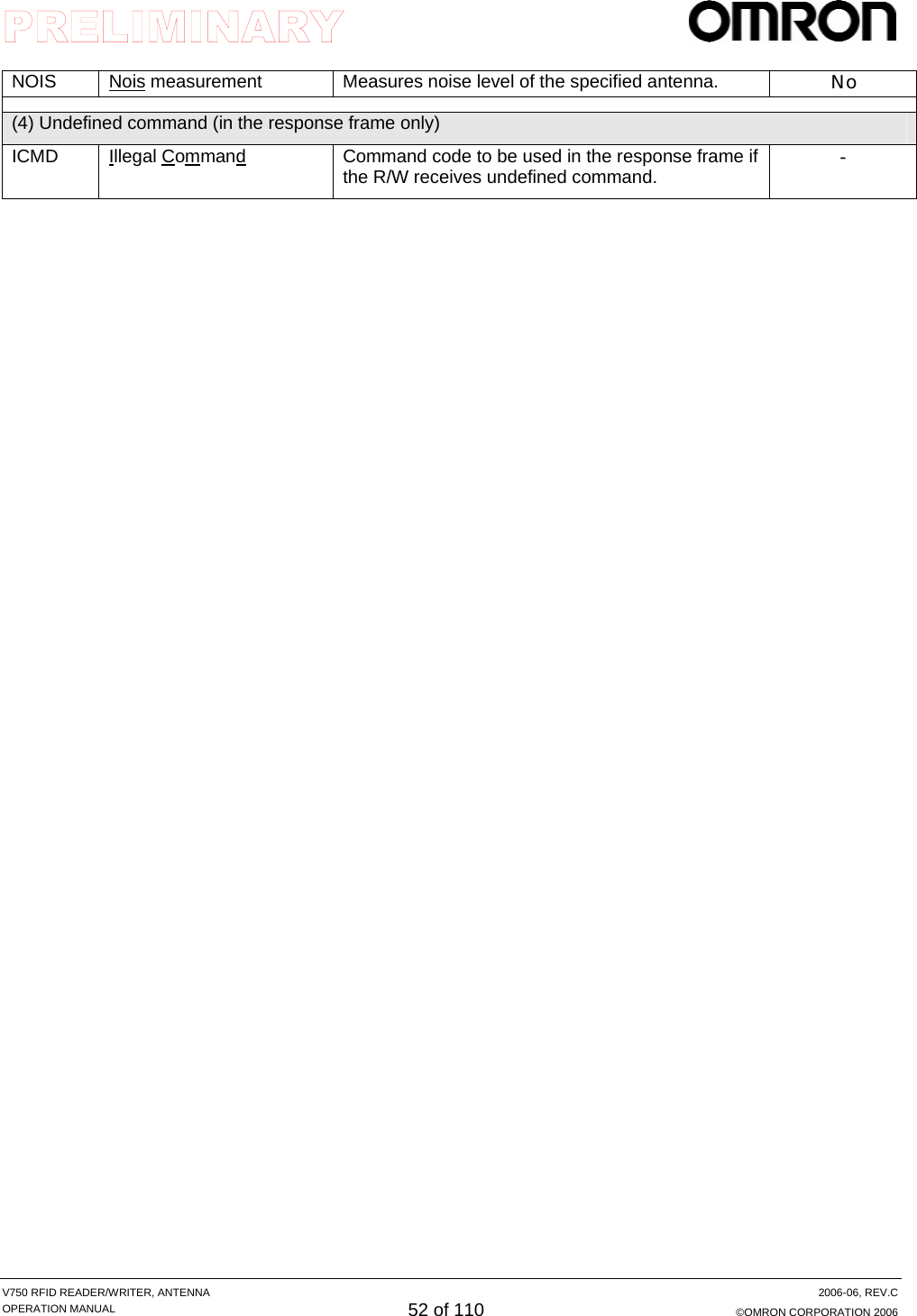
![V750 RFID READER/WRITER, ANTENNA 2006-06, REV.C OPERATION MANUAL 49 of 110 ©OMRON CORPORATION 2006 Terminator [CR,0x0d] Indicates the end of the frame with CR,0x0d. No Yes Terminator [LF,0x0a] Indicates the end of the frame with LF,0x0a. Yes Yes Response frame for Ethernet Response frame for RS-232C Contents in command frame Contents Description Ethernet required? RS-232Crequired?Start code [SOH,0x01] Indicates the beginning of the frame with SOH,0x01. No Yes Command code Specifies the command the Reader executes. Yes Yes Response data Indicates the results of command execution. Yes Yes FCD Stands for Frame Check Data No Yes Terminator [CR,0x0d] Indicates the end of the frame with CR,0x0d. No Yes Terminator [LF,0x0a] Indicates the end of the frame with LF,0x0a. Yes Yes Command Code Response Code Response Data LF4 bytes 4 n 1 SOH Command Code Response Code Response Data FCD CR LF1 4 4 n 2 1 1 FCC Calculation Area](https://usermanual.wiki/Omron-RFID-Business-Development-Department/V750-BA50C04/User-Guide-714521-Page-49.png)
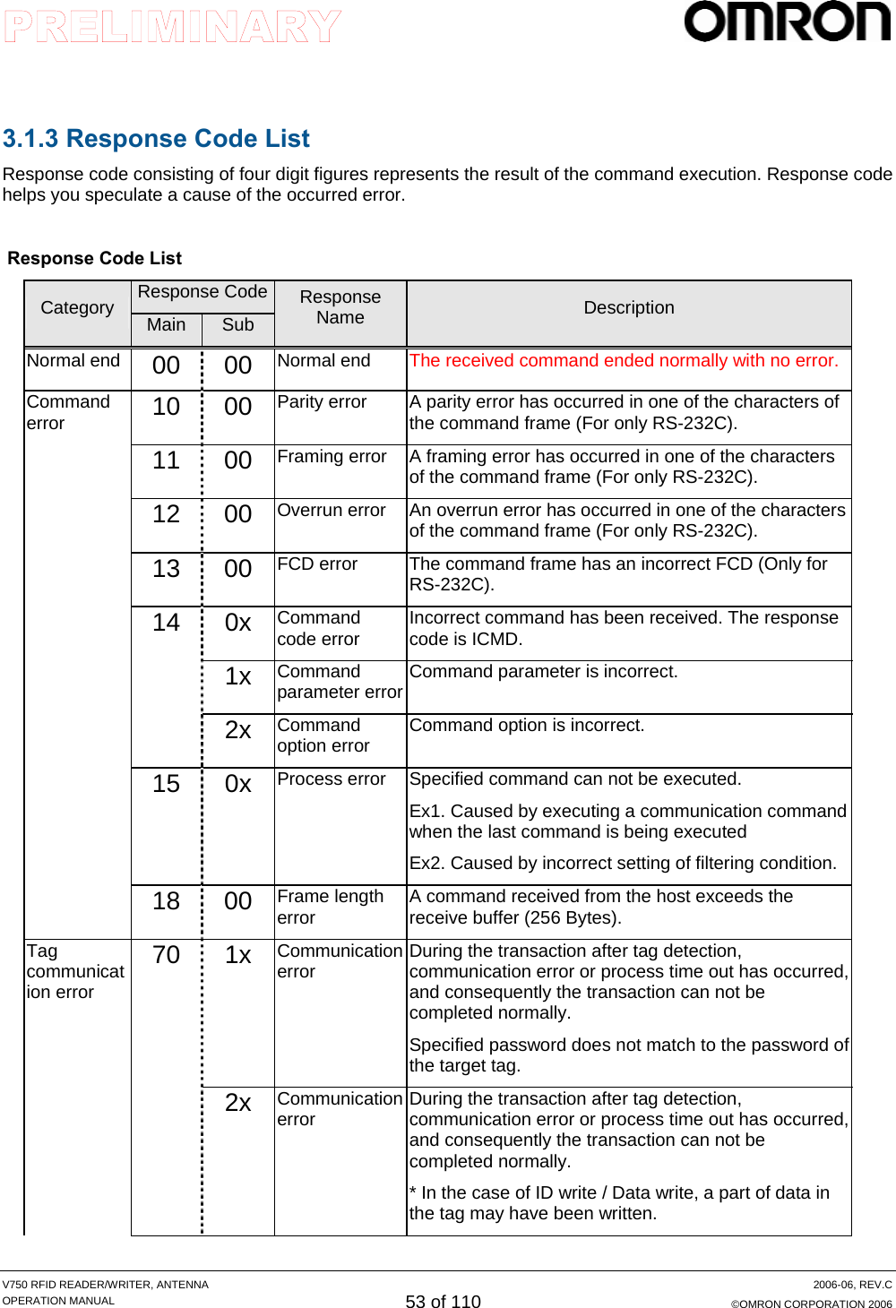
![V750 RFID READER/WRITER, ANTENNA 2006-06, REV.C OPERATION MANUAL 50 of 110 ©OMRON CORPORATION 2006 How to calculate FCC in frame for RS-232C. Calculate XOR (Exclusive OR) of figures included in the range of FCD calculation and put the result as a ACSII code at the end of the command. An example of FCD calculation: Command code and Command data: RDID –seq MOC –ant 1 –tmo 500 FCD value: 19 Command frame: [SOH]RDID –seq MOC –ant 1 –tmo 50019[CR][LF] Calculation Character ASCII Code (Hex) Binary R 52 01010010 D 44 01000100 I 49 01001001 D 44 01000100 (Space) 20 00100000 - 2C 00101100 s 73 01110011 e 65 01100101 q 71 01110001 (Space) 20 00100000 M 4C 01001100 O 4F 01001111 C 43 01000011 (Space) 20 00100000 - 2C 00101100 a 61 01100001 n 6E 01101110 t 74 01110100 (Space) 20 00100000 1 31 00110001 (Space) 20 00100000 - 2C 00101100 t 74 01110100 m 6C 01101100 o 6F 01101111 (Space) 20 00100000 5 35 00110101 0 30 00110000 0 30 00110000 XOR 19 00011001](https://usermanual.wiki/Omron-RFID-Business-Development-Department/V750-BA50C04/User-Guide-714521-Page-50.png)
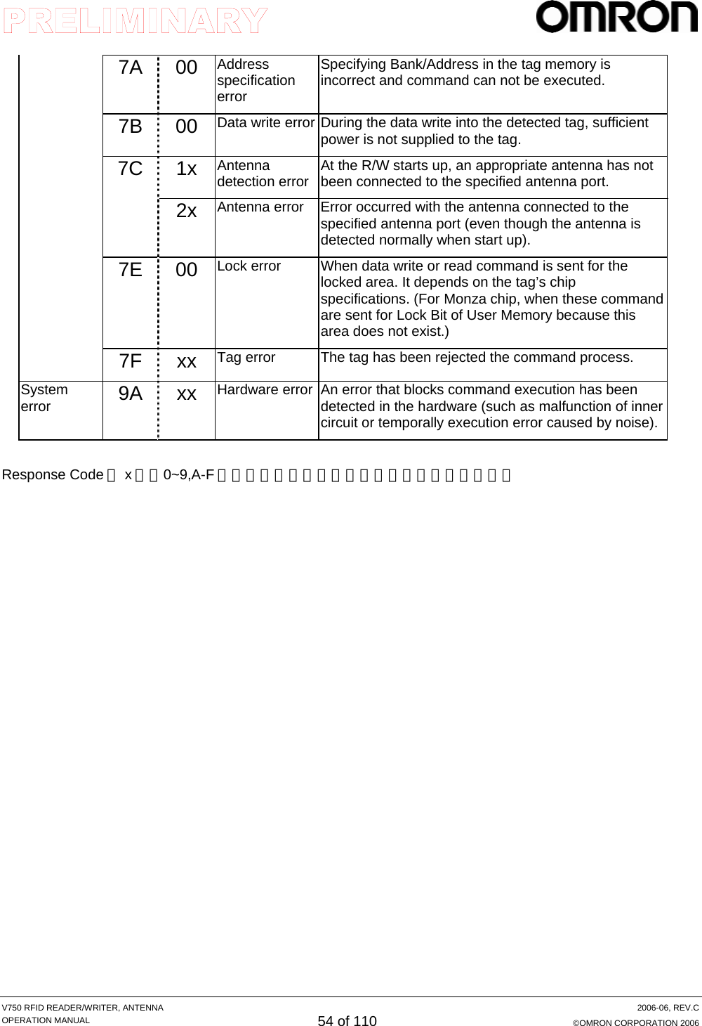
![V750 RFID READER/WRITER, ANTENNA 2006-06, REV.C OPERATION MANUAL 56 of 110 ©OMRON CORPORATION 2006 Command Code, Response Code and Response Data format in Response Frame * All hexadecimal numbers as commands and data in the read tags are indicated with capitals (A to F). Response Data Area Command Code Response Code SP DATA1 SP DATA2 ・・・ DATAn 4 Bytes 4 1 n1nnn Command Code Set same characters specified as a command sent from the host. Response Code Indicates four-digit hexadecimal numbers. Response Data Returns the some data executed by R/W. Example1: No. of tags for communication commands Example2: The tag ID(s) (or data) read by R/W with Hex code. If R/W reads multiple tags’ IDs (or data), it indicates them in line with space(s) between each ID (or data). Data in hexadecimal numbers does not need [0x].](https://usermanual.wiki/Omron-RFID-Business-Development-Department/V750-BA50C04/User-Guide-714521-Page-56.png)
![V750 RFID READER/WRITER, ANTENNA 2006-06, REV.C OPERATION MANUAL 60 of 110 ©OMRON CORPORATION 2006 [Note] For setting a timeout value, 100ms or less shall not be specified under the repeat mode (SRP/ MRP). If so, the Reader/Writer may freeze (setting error may occur) depending on the communication performance of the Ethernet or RS-232C. If Ethernet’s traffic is large or the communication speed setting for RS-232C is low, the value shall be set longer.](https://usermanual.wiki/Omron-RFID-Business-Development-Department/V750-BA50C04/User-Guide-714521-Page-60.png)
![V750 RFID READER/WRITER, ANTENNA 2006-06, REV.C OPERATION MANUAL 61 of 110 ©OMRON CORPORATION 2006 ■ Example of command/ response ReaD ID (RDID) Command RDID (S) [options...]<LF> Response RDID[RC] (S) [CNT] (S) [ID1 with ITM1] (S)... [IDn with ITMn]<LF> [RC] Response Code [CNT] Tag Count [IDn with ITMn] tagID with Items indicated by TIF option. Items are delimited by a comma. If EPC data length is “0” (zero), the ID shall be “*”. *(S) Space character Example 1) When command is processed with all options omitted and the R/W reads a single tag (Each option item is specified with default values): [Tx] RDID<LF> [Rx] RDID0000 001 1234567890ABCDEF12345678<LF> (Without any options, the command is executed with Seq=SOC/ ant=1/ tmo=250 and EPC data [1234567890ABCDEF12345678] is returned.) Example 2) When [SingleOnce, Antenna 1 and 2] is specified, the command is executed, and when the R/W reads two tags: [Tx] RDID -seq MOC -ant 12<LF> [Rx] RDID0000 002 111111111111111111111111 222222222222222222222222<LF> Example 3) When [MultiRepeat, Antenna 1-4, read items; PC+EPC+CRC, Antenna, Protocol, Read count] is specified, the command is executed, and when the R/W reads a single tag: [Tx] RDID -seq MRP -ant 1234 -tif PER,ANT,PTC,CNT<LF> [Rx] RDID0000 001 3000111111111111111111111111ABCD,2,1,3 <LF> (The code is returned with comma-separation. EPC code including PC code; 3000 and CRC; ABCD, antenna ID; 2, protocol ID; 1, and read count; 3 are returned) Example 4) When [MultiRepeat, Antenna; 1-4 (Antenna 1 is used as main antenna), Timeout; 1000msec] is specified, the command is executed and then the R/W read 10 tags: [Tx] RDID -seq MRP -ant12131411 -tmo 1000<LF> [Rx] RDID0000 010 111111111111111111111111 222222222222222222222222 ...(7 Tag IDs)... AAAAAAAAAAAAAAAAAAAAAAAA<LF> Example 5) When an error occurred during communication process: [Tx] RDID -seq SOC -ant 4<LF> [Rx] RDID7000<LF> (The error code [Code:7011] is returned.)](https://usermanual.wiki/Omron-RFID-Business-Development-Department/V750-BA50C04/User-Guide-714521-Page-61.png)
![V750 RFID READER/WRITER, ANTENNA 2006-06, REV.C OPERATION MANUAL 62 of 110 ©OMRON CORPORATION 2006 (2) WriTe ID (WTID) Command WTID (S) dat (S)[Options]...<LF> dat : Data to be written Response WTID[RC] (S) [CNT] (S) [ITM1]<LF> [RC] Response Code [CNT] Tag Count [ITM1] Items indicated by TIF option. Items are delimited by a comma. If EPC/PEP/PER are specified for TIF, EPC data shall be the data before rewrite. If Data length is zero during EPC specification, data shall become ”*”. *(S) Space character Example 1) When all set values are default values and ID 1234567890ABCDEF12345678 is specified, the command is executed and write process has been completed successfully: [Tx] WTID 1234567890ABCDEF12345678<LF> [Rx] WTID0000 001<LF> Example 2) When ANT and 1234567890ABCDEF12345678 are specified for Tag InFormation, Write data and the command is executed and then R/W has succeeded to write data with Antenna 1. [Tx] WTID 1234567890ABCDEF12345678 -tif EPC,ant<LF> [Rx] WTID0000 001*, 1<LF> If tif is specified for EPC code, tag’s EPC data before rewritten is returned. If the tag has no EPC data, [*] is returned. Example 3) When FFFFFFFFFFFFFFFFFFFFFFFF, 2, and 300 are specified for ID, antenna, and TimeOut and the command is executed but no tag is found: [Tx] WTID FFFFFFFFFFFFFFFFFFFFFFFF -ant 2 -tmo 300<LF> [Rx] WTID0000 000<LF> Example 4) When an error has occurred during communication process: [Tx] WTID 1234567890ABCDEF12345678<LF> [Rx] WTID7F00<LF> * The error code is added to the response code.](https://usermanual.wiki/Omron-RFID-Business-Development-Department/V750-BA50C04/User-Guide-714521-Page-62.png)
![V750 RFID READER/WRITER, ANTENNA 2006-06, REV.C OPERATION MANUAL 63 of 110 ©OMRON CORPORATION 2006 (3) ReaD Data (RDDT) Command RDDT(S) mbk (S) dpt (S) dln (S)[options...]<LF> mbk: Memory Bank dpt: Data Pointer dln; Data Length Response RDDT[RC] (S) [CNT] (S) [Data1 with ITM1] <LF> [RC] Response Code [CNT] Tag Count [Data with ITM] Data with Items indicated by TIF option. Items are delimited by a comma. *(S) Space Character Example 1) When [Memory bank; 2, start address; 16, word count to be read; 4] is specified, other settings are default value and then read process has completed successfully: [Tx] RDDT 2 16 4<LF> [Rx] RDDT0000 001 1111222233334444<LF> Example 2) When [Memory bank; 0x01, start address; 0x02, word count to be read; 0x03, Antenna; 1- 3] is specified and read process has succeeded: [Tx] RDDT 0x01 0x02 0x03 -ant 123 -tif EPC,ANT<LF> [Rx] RDDT0000 001 111122223333, 1234567890ABCDEF12345678,2<LF> (In this case, the read data is [111122223333], the tag EPC code is [1234567890ABCDEF12345678], and the read antenna ID is [2].) Example 3) When an incorrect address is specified: [Tx] RDDT 0 0x100 0x1 -ant 123<LF> [Rx] RDDT1412<LF> (The command data error [Code:1412] is returned.) Example 4) When an error has occurred during communication process: [Tx] RDDT 0 0 1 -ant 123<LF> [Rx] RDDT7000<LF> The error code is returned.](https://usermanual.wiki/Omron-RFID-Business-Development-Department/V750-BA50C04/User-Guide-714521-Page-63.png)
![V750 RFID READER/WRITER, ANTENNA 2006-06, REV.C OPERATION MANUAL 64 of 110 ©OMRON CORPORATION 2006 (4)WriTe DaTa (WTDT) Command WTDT (S) mbk (S) dpt (S) dln (S) [options...]<LF> mbk: Memory Bank dpt: Data Pointer dln; Data Length Response WTDT[RC] (S) [CNT] (S) [ITM1] <LF> [RC] Response Code [CNT] Tag Count [ITM1] Items indicated by TIF option. Items are delimited by a comma. If EPC/PEP/PER are specified for TIF, EPC data shall be the data before rewrite. If Data length is zero during EPC specification, data shall become ”*”. *(S) Space Character Example 1) When [Memory bank; 0, Start address; 0, Data; 0x12345678] is specified, other setting are default and then the write process has been succeeded: [Tx] WTDT 0 0 12345678<LF> [Rx] WTDT0000 001<LF> Example 2) When [Memory bank;1, Start address; 32, word count to be written ;6, Data; 0x1234567890ABCDEF12345678 , ANT: 2-3, Time Out: 200] is specified: [Tx] WTDT 1 32 1234567890ABCDEF12345678 -ant 23 -tmo 200 –tif ANT<LF> [Rx] WTDT0000 001 2<LF> * In this case, write command is processed with Antenna 2. Example 3) When [Memory bank; 0x00, Start address; 0x00, Data; 0x00 ABCDEFGH] is specified and a format error has occurred. [Tx] WTDT 0x00 0x00 ABCDEFGH<LF> [Rx] WTDT1412<LF> * The error code [1412] is returned. Example 4) When an error occurred during communication process. [Tx] WTDT 1 32 1234567890ABCDEF12345678 -ant 23 <LF> [Rx] WTDT7011<LF> * The error code [7011] is returned.](https://usermanual.wiki/Omron-RFID-Business-Development-Department/V750-BA50C04/User-Guide-714521-Page-64.png)
![V750 RFID READER/WRITER, ANTENNA 2006-06, REV.C OPERATION MANUAL 65 of 110 ©OMRON CORPORATION 2006 (5) LOCK (LOCK) Command LOCK (S) lkc (S) [options...]<LF> lkc: Lock Code (10 characters 0/1/*) Response LOCK[RC] (S) [CNT] (S) [ITM1]<LF> [RC] Response Code [CNT] Tag Count [ITM1] Items indicated by TIF option. Items are delimited by a comma. *(S) Space Character Example 1) When [Password; 0x12341234, EPC memory; locked temporally] is set: [Tx] LOCK ****10**** –pwd 12341234<LF> [Rx] LOCK0000 001<LF> Example 2) When [Password; 0xFFFFFFFF, all memory are locked permanently, and antenna; 2] is set: [Tx] LOCK 1111111111 –pwd FFFFFFFF -ant 2 –tif EPC<LF> [Rx] LOCK0000 001 1234567890ABCDEF12345678<LF> *The EPC code of the tag is [1234567890ABCDEF12345678]. Example 3) When [Password; 0x12341234 and all memories are permanently locked] is specified incorrectly: [Tx] LOCK 1111111111 –pwd 12341234<LF> [Rx] LOCK7011<LF> * The communication error [7011] is returned. Example 4) When [Password; 0xFFFFFFFF] is specified and specified lock code is incorrect: [Tx] LOCK 2222222222 –pwd FFFFFFFF -ant 2<LF> [Rx] LOCK1411<LF> * The error code [1411] is returned.](https://usermanual.wiki/Omron-RFID-Business-Development-Department/V750-BA50C04/User-Guide-714521-Page-65.png)
![V750 RFID READER/WRITER, ANTENNA 2006-06, REV.C OPERATION MANUAL 66 of 110 ©OMRON CORPORATION 2006 (6)Kill (KILL) Command KILL (S) [options...]<LF> Option “pwd” is mandatory. Response KILL[RC] (S) [CNT] (S) [ITM1] <LF> [RC] Response Code [CNT] Tag Count [ITM1] Items indicated by TIF option. Items are delimited by a comma. *(S) Space Character Example 1) When [Password; 0x22222222] is specified and then KILL command is completed normally: [Tx] KILL –pwd 22222222<LF> [Rx] KILL0000 001<LF> Example 2) When [Antenna; 3, Password; 0xAAAABBBB, items; PER and ANT] is specified and KILL command has completed normally: [Tx] KILL –pwd AAAABBBB -ant 3 -tif PER,ANT<LF> [Rx] KILL0000 001 30001234567890ABCDEF12345678ABCD,3<LF> * The PC code of the tag is [3000], EPC code is [1234567890ABCDEF12345678], CRC is [ABCD], and command executed Antenna ID is [3]. Example 3) When [Password; 0x12345678] is specified and password has turned out incorrect: [Tx] KILL –pwd 12345678<LF> [Rx] KILL7012<LF> * The error code [7012] is returned. Example 4) When [Password; 0x12] is specified and password has turned out incorrect: [Tx] KILL –pwd 12<LF> [Rx] KILL1421<LF> * The error code [1421] is returned.](https://usermanual.wiki/Omron-RFID-Business-Development-Department/V750-BA50C04/User-Guide-714521-Page-66.png)
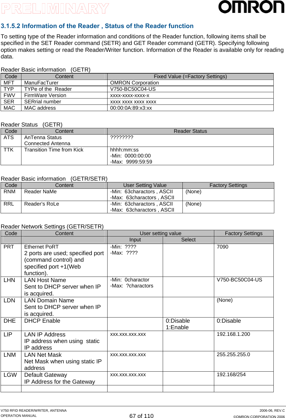
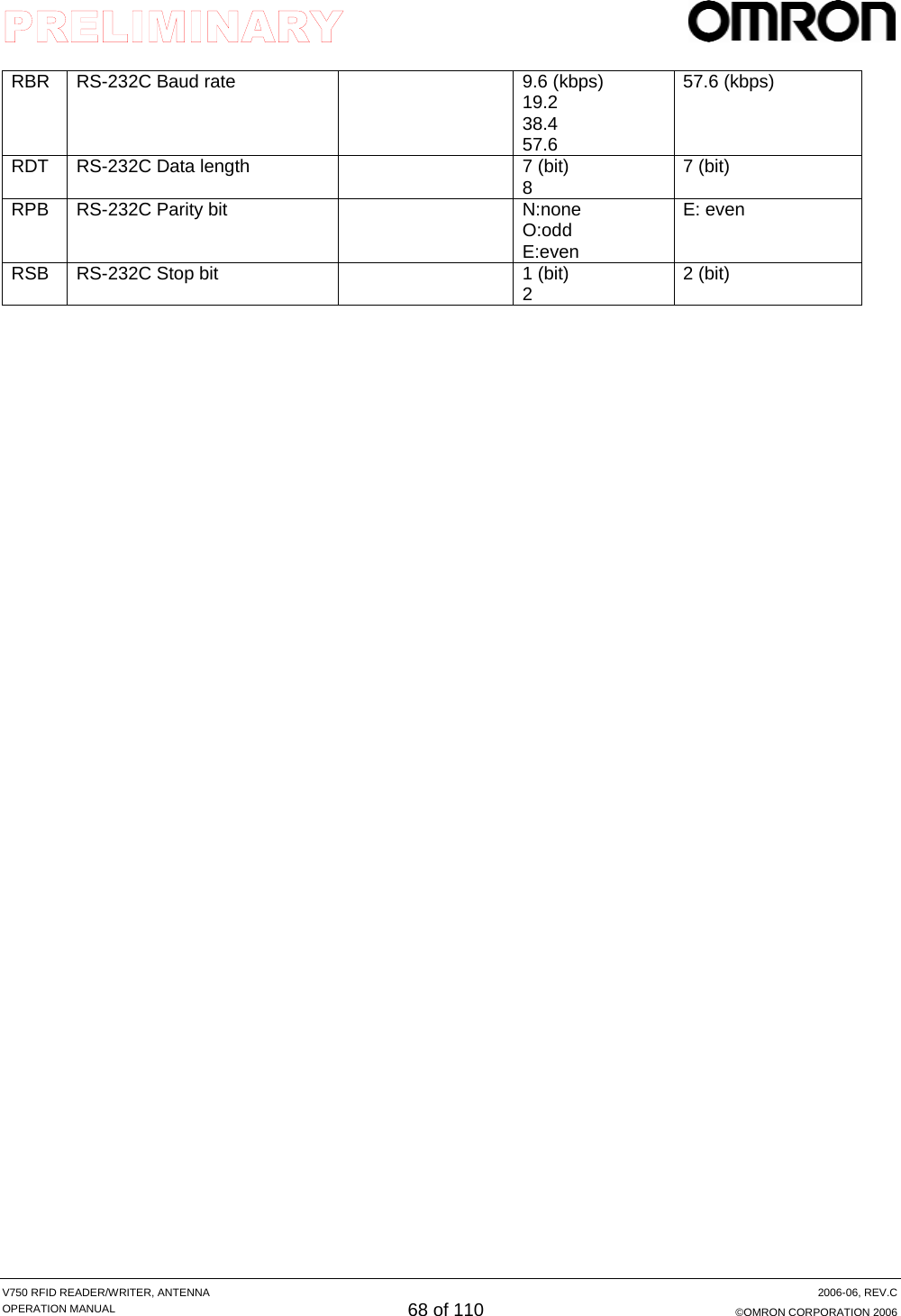
![V750 RFID READER/WRITER, ANTENNA 2006-06, REV.C OPERATION MANUAL 69 of 110 ©OMRON CORPORATION 2006 (1) SET Reader function (SETR) This command writes the functional conditions of the command in process into the nonvolatile memory in the Reader/ Writer. The setting shall be enabled at the upcoming startup. Command SETR (S) param1=value1 (S)...param n=value n<LF> It specifies a parameter connecting a setting item to a setting value with equal. (The setting item does not have to be prepended with ‘ -‘.) No space shall be put in from the beginning of the setting item to the end of the setting value. If the setting value includes any space, the space shall be enclosed with double quotation. In a single command, multiple setting items can be specified by separating with space. A 2 or more character space is acceptable for indicating separation. Response SETR0000<LF> *(S) Space Character Example 1) When DHCP Enabled is set “ON”: [Tx] SETR dhe=1<LF> [Rx] SETR0000<LF> Example 2) When [Host name; V750-BA50C04, IP; 192.168.1.1, and Net Mask; 255.255.255.0] is set: [Tx] SETR lhn=“V750 BA50C04” lip=192.168.1.1 lnm=255.255.255.0<LF> [Rx] SETR0000<LF> Example 3) When [RS-232C Baud rate; 19200bps, Data length; 7bit, Parity; Even, and Stop; 1bit] is set: [Tx] SETR rbr=19200 rdt=7 rpb=E rsb=1<LF> [Rx] SETR0000<LF> Example 4) When the setting item is incorrect: [Tx] SETR xxx=111<LF> [Rx] SETR1407<LF>](https://usermanual.wiki/Omron-RFID-Business-Development-Department/V750-BA50C04/User-Guide-714521-Page-69.png)
![V750 RFID READER/WRITER, ANTENNA 2006-06, REV.C OPERATION MANUAL 70 of 110 ©OMRON CORPORATION 2006 (2) GET Reader (GETR) This command allows the Reader/Writer to read the current functional conditions. Even after SET Reader command (SETR) is executed, the old information shall be read out unless the reboot is completed. Command GETR (S) param1 (S) param2...<LF> It specifies a parameter connecting a setting item to a setting value. (‘The setting item does not have to be prepended with ‘ -‘ .) In a single command multiple setting items can be specified by separating with space. A 2 or more character space is acceptable for indicating separation. Response GETR (S) param1=value1 (S) ...param n = value n<LF> If multiple items are specified, the Reader/Writer shall return response with connecting specified items to the setting values with equal in the specified order. Alphabetical characters included in the item name in the response shall be small characters. If the setting value includes any space, the space shall be enclosed with double quotation. *(S) Space Character Example 1) When [Firmware version;100-100-100-0] is read: [Tx] GETR fwv<LF> [Rx] GETR0000 fwv=100-100-100-0<LF> Example 2) When [Host name; V750-BA50C04, IP; 192.168.1.1, and Net Mask; 255.255.255.0] is read: [Tx] GETR lhn lip lnm<LF> [Rx] GETR0000 lhn=V750-BA50C04 lip=192.168.1.1 lnm=255.255.255.0 <LF> Example 3) When [RS-232C Baud rate; 19200bps, Data length; 7 bit, Parity; even, and Stop; 1bit] is read: [Tx] GETR rbr rdt rpb rsb<LF> [Rx] GETR0000 rbr=19200 rdt=7 rpb=E rsb=1<LF> [Tx] GETR rbr rdt rpb rsb<LF> [Rx] GETR0000 rbr=19200 rdt=7 rpb=E rsb=1<LF>](https://usermanual.wiki/Omron-RFID-Business-Development-Department/V750-BA50C04/User-Guide-714521-Page-70.png)
![V750 RFID READER/WRITER, ANTENNA 2006-06, REV.C OPERATION MANUAL 72 of 110 ©OMRON CORPORATION 2006 OT3 Output port #3 function setting Same as OT1 (None) OT4 Output port #4 function setting Same as OT1 (None) ● If the NML mode is specified in output function setting, you can set conditions by using the following format. Condition(A) Condition(B) Dynamic comparison data “DAT”: data (リードしたタグデータ) “TCT”: tag count (リードしたタグ枚数) Comparison operators “==”:Data match ”!=”:Data unmatch “>=”:data value or more ”<=”:data or less When comparison data is “TCT”, the code is able to be specified. Static comparison data 00∼ [Hex] *mark is a wild card (effective only for Data matched or Data unmatched ) Logical operator “&”:AND operator Format: condition A & condition B “|”: OR operator Format: condition A | condition B * If there is no condition to be set or condition (A) is set, condition (B) shall not be included in the setting. Ex.) When the characters from 5th to 8th in read data or when the number of tags is 8 or more, "DAT==XXXX0000|TCT>=8" ● In the case that ERR mode is specified for output function setting, you can set conditions with the following format. Conditions Error code specifying. Error code: Specified error has occurred (Max 6 code can be specified.) ex. ”7071”・・・ * If there is no condition to be set, any condition shall not be specified. Ex.) When communication error or verify error has been occurred, "dat==7071"](https://usermanual.wiki/Omron-RFID-Business-Development-Department/V750-BA50C04/User-Guide-714521-Page-72.png)
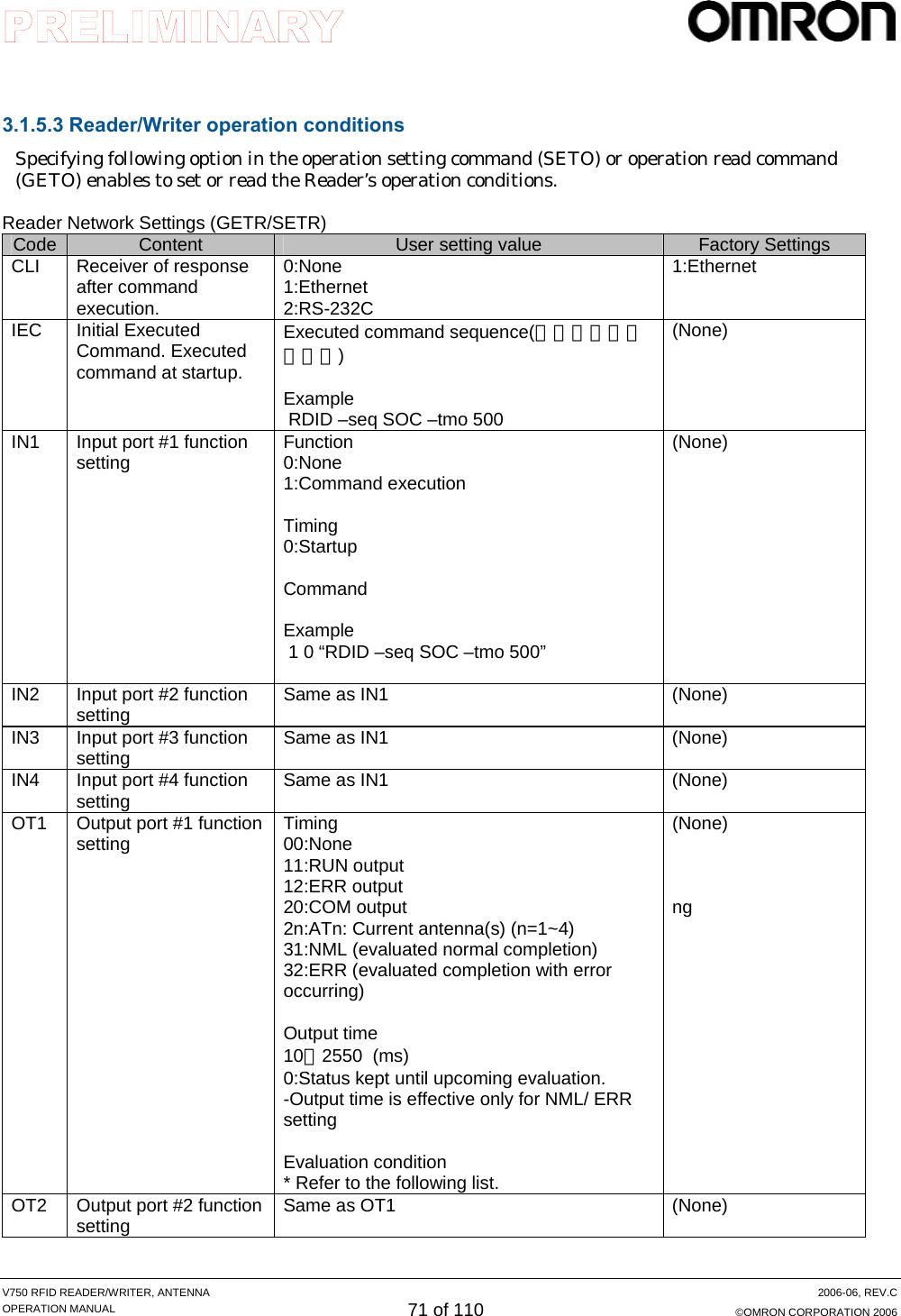
![V750 RFID READER/WRITER, ANTENNA 2006-06, REV.C OPERATION MANUAL 73 of 110 ©OMRON CORPORATION 2006 (1) Set Operation of Reader (SETO: ST Operation) This command is to write operation conditions into the nonvolatile memories in the Reader/Writer. The new setting shall be enabled at the upcoming startup. Command SETO (S) param1=value1<LF> Putting equal between a single setting item and a setting value specifies the value (no need to put ‘-‘ before setting item). * Multiple setting items can not be applicable. Response SETO0000<LF> *(S) Space Character Example 1) When the receiver of response after command execution is set RS-232, [Tx] SETO cli=2<LF> [Rx] SETO0000<LF> Example 2) When the executed command at the start up is set as [rdid -ant 122322 -tmo 100] , [Tx] SETO iec="rdid -ant 122322 -tmo 100"<LF> [Rx] SETO0000<LF> Example 3) When Input 1 function setting is set as [Command execution, start up edge," rdid -ant 122322 -tmo 100"], [Tx] SETO in1=1 0 "rdid -ant 122322 -tmo 100"<LF> [Rx] SETO0000<LF> Example 4) When output 2 function setting is set [output time;500ms when ERR], [Tx] SETO ot2=01 500 [Rx] SETO0000<LF> Example 5) When output 2 function setting is set as; if data read from memory bank1 and address 2 is XXXX0000 after data read completes normally, output status shall be kept until upcoming evaluation, 出力 3機能設定を、正常読取り完了時、メモリバンク 1、アドレス 2から読み出したデータが XXXX0000 のときに次回の判定まで出力状態を保持する場合 [Tx] SETO ot3=31 0 1 2 dat=XXXX0000 [Rx] SETO0000<LF>](https://usermanual.wiki/Omron-RFID-Business-Development-Department/V750-BA50C04/User-Guide-714521-Page-73.png)
![V750 RFID READER/WRITER, ANTENNA 2006-06, REV.C OPERATION MANUAL 74 of 110 ©OMRON CORPORATION 2006 (2) Get operation of reader (GETO: GET Operation) This command allows the Reader/Writer to read the current operation conditions. Even after setting operation command (SETO) is executed, the old information shall be read out unless the reboot is completed. Command GETO (S) param1 (S) ... param n<LF> Specifies a single setting item. (not required ‘-‘ before the item) * Multiple setting items cannot not be specified. Response GETO (S) param1=value1 (S)<LF> *(S) Space Character Example 1) When executed command is read at startup, [Tx] GETO iec<LF> [Rx] GETO0000 iec=" rdid -ant 122322 -tmo 100"<LF> Example 2) When Input 1 function setting is read, [Tx] GETO in1<LF> [Rx] GETO0000 in1=1 0 "rdid -ant 122322 -tmo 100"<LF> Example 3) When Output 1 function setting is read, [Tx] GETO ot1<LF> [Rx] GETO0000 ot2="31 0 mbk 1 dpt 2 dat=XXXX0000"<LF>](https://usermanual.wiki/Omron-RFID-Business-Development-Department/V750-BA50C04/User-Guide-714521-Page-74.png)
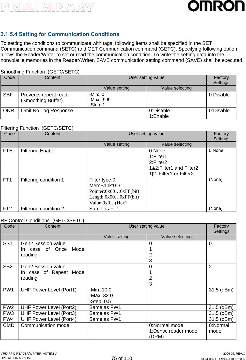

![V750 RFID READER/WRITER, ANTENNA 2006-06, REV.C OPERATION MANUAL 77 of 110 ©OMRON CORPORATION 2006 (1) SET Communication (SETC) While the command is being executed, setting conditions in the Reader/ Writer are changed. This setting is enabled when another communication command is executed. To write the setting data into the nonvolatile memories in the Reader/Writer, SAVE communication setting command (SAVE) shall be executed. The new setting shall be enabled at the upcoming startup. Command SETC (S) param1=value1 (S)... param n=value n<LF> It specifies a parameter connecting a setting item to a setting value. (‘The setting item does not have to be prepended with ‘ -‘ .) No space shall be put in from the beginning of the setting item to the end of the setting value unless setting item is ft1 or ft2. If the setting item is ft1 and/or ft2, the five items shall be specified with space separation between each item. Instead of space, enclosing double quotations is not allowable. In a single command, multiple setting items can be specified by separating with space. A 2 or more character space is acceptable for indicating separation. Response SETC0000<LF> *(S) Space Character Example 1) When [Port 1 power; 10, Session; S1]is specified: [Tx] SETC cp1=10 ss1=1<LF> [Rx] SETC0000<LF> Example 2) When [Filter; 1 or 2, Filter1; Bank 1, Address; 20, Dat; 0x**11, Filter2; Bank 1, Data Pointer; 20, Dat; 0x1211] is specified: [Tx] SETC ft1=0 1 20 XX11<LF> [Rx] SETC0000<LF> [Tx] SETC ft2=0 1 20 1211<LF> [Rx] SETC0000<LF> [Tx] SETC fte=1|2 <LF> [Rx] SETC0000<LF>](https://usermanual.wiki/Omron-RFID-Business-Development-Department/V750-BA50C04/User-Guide-714521-Page-77.png)
![V750 RFID READER/WRITER, ANTENNA 2006-06, REV.C OPERATION MANUAL 78 of 110 ©OMRON CORPORATION 2006 (2) GET Communication (GETC) This command allows the Reader/ Writer to read the current communication conditions. Just after SET Communication command (SETC) is executed, new information shall be read out. Command GETC (S) param1 (S) param n<LF> It specifies a parameter connecting a setting item to a setting value. (‘The setting item does not have to be prepended with ‘ -‘ .) In a single command, multiple setting items can be specified by separating with space. (A 2 or more character space is acceptable for indicating separation.) Response GETC0000 (S) param1=value1 (S) ... param n=value n<LF> If multiple items are specified, the Reader/Writer shall return response with connecting specified items to the setting values with equal in the specified order. Alphabetical characters included in the item name in the response shall be small characters. If the setting item is ft1 and/or ft2, the five items shall be returned with space separation between each item. Double quotations shall not be used for enclosing. *(S) Space Character Example 1) When [UHF power, Session] is read out: [Tx] GETC cpw ss1<LF> [Rx] GETC0000 cpw=10 ss1=1<LF> Example 2) When [Filter setting, Filter condition 1, Filter condition 2] is read out: [Tx] GETC fte fl1 fl2<LF> [Rx] GETC0000 fte=1&2 ft1=0 1 20 XX11 ft2=0 1 20 1211<LF>](https://usermanual.wiki/Omron-RFID-Business-Development-Department/V750-BA50C04/User-Guide-714521-Page-78.png)
![V750 RFID READER/WRITER, ANTENNA 2006-06, REV.C OPERATION MANUAL 79 of 110 ©OMRON CORPORATION 2006 (3) SAVE communication setting (SAVE) This command allows the Reader/Writer to write communication setting into the nonvolatile memories in the Reader/Writer. If SET Communication command (SETC) is executed and then the Reader/ Writer is started up without executing this command(SAVE), new setting will be abandoned. Command SAVE<LF> No arguments. * In the future, the function will be extended so that the Reader/Writer can write data into a certain area with specifying the area. ex. SAVE 0(<= specified area number ) Response SAVE0000<LF> Example 1) When communication setting is saved (New setting is written into the nonvolatile memory): [Tx] SAVE [Rx] SAVE0000](https://usermanual.wiki/Omron-RFID-Business-Development-Department/V750-BA50C04/User-Guide-714521-Page-79.png)
![V750 RFID READER/WRITER, ANTENNA 2006-06, REV.C OPERATION MANUAL 80 of 110 ©OMRON CORPORATION 2006 3.1.5.5 Control Command (1)INITialize setting (INIT) This command initializes all setting of reader so that all setting will return to factory default setting. All setting shall be written into the inner nonvolatile memories. After executing this INIT command, the Reader/Writer requires reboot. Command INIT<LF> No argument ex. INIT 1(← Initilized range) Response INIT0000<LF> Example 1) All setting of reader is initialized to the factory default setting. [Tx] INIT [Rx] INIT0000](https://usermanual.wiki/Omron-RFID-Business-Development-Department/V750-BA50C04/User-Guide-714521-Page-80.png)
![V750 RFID READER/WRITER, ANTENNA 2006-06, REV.C OPERATION MANUAL 81 of 110 ©OMRON CORPORATION 2006 (1) External Input Output control (EXIO) This command allows the Reader /Writer to output ON/OFF to the output terminal and read an input terminal status. If output setting value is omitted, the Reader/Write shall read the input status only. Command EXIO <LF> (For only input status read) EXIO (S) outd<LF> (For output specifying) outd: For OUT1-4, values are set with four characters (left to the right; 1-4) (”0”-OFF/”1”-ON/”*”-Don’t care) Response EXIO0000 (S) inpd (S) outd<LF> inpd: For IN1-4, values 2-4 are set with four characters (left to the right). (”0”-OFF/”1”-ON) *(S) Space Character Example 1) When [Output 1; High, Output 2; Low, Output 3; High, Output 4; Low] is specified: [Tx] EXIO 1010 [Rx] EXIO0000 1111 1010 Example 2) When [Getting I/O status] is specified: [Tx] EXIO<LF> [Rx] EXIO0000 1011 1001<LF> (From the left side, the following status is shown; IN1...IN4, OUT1…OUT4)](https://usermanual.wiki/Omron-RFID-Business-Development-Department/V750-BA50C04/User-Guide-714521-Page-81.png)
![V750 RFID READER/WRITER, ANTENNA 2006-06, REV.C OPERATION MANUAL 82 of 110 ©OMRON CORPORATION 2006 (2) RESeT (RSET) This command reboots the Reader/Writer after the Reader/ Writer returns the response indicating command receipt. Command RESET<LF> Nor arguments. * In the future, the function will be extended so that it can specify reset level. ex. RESET 1 (<= Reset level) Response REST0000<LF> Example 1) When all the settings of the Reader/Writer are initialized to factory default setting:。 [Tx] REST<LF> [Rx] REST0000<LF> (3) STOP the operation (STOP) This command instructs the Reader/Writer to stop the operation in process. Command STOP<LF> No arguments Response STOP0000<LF> Example 1) When the Reader/Writer stops multi-repeat communication: [Tx] RDID -seq MRP -ant 12 ---- ReaD ID command starts multi-repeat. [Tx] STOP<LF> [Rx] STOP0000<LF>](https://usermanual.wiki/Omron-RFID-Business-Development-Department/V750-BA50C04/User-Guide-714521-Page-82.png)
![V750 RFID READER/WRITER, ANTENNA 2006-06, REV.C OPERATION MANUAL 83 of 110 ©OMRON CORPORATION 2006 (4) Good BYE (GBYE) - Connection shut down This command enables to shut down connection with Ethernet. This command is valid only when Connection Method is Passive. (Error occurs if the mode is Active.) The communication of response that indicates command receipt is shut down (disconnected?) after sending. Command GBYE<LF> No argument Response GBYE0000<LF> Example 1) All setting of the reader shall be initialized to factory default setting. [Tx] GBYE<LF> [Rx] REST0000<LF>](https://usermanual.wiki/Omron-RFID-Business-Development-Department/V750-BA50C04/User-Guide-714521-Page-83.png)
![V750 RFID READER/WRITER, ANTENNA 2006-06, REV.C OPERATION MANUAL 84 of 110 ©OMRON CORPORATION 2006 (6) RERESponse (RERES) This command instructs the Reader/Writer to re-send the latest response data that has been sent. This command shall not be accepted when the other command such as Repeat mode is being processed. REPEAT 系 Command RRES<LF> No argument Response (The latest response) Example 1) When the host requests to resend the response for the External Input Output control command (EXIO) that has been executed most lately. [Tx] RRES<LF> [Rx] EXIO0000 1011 1001<LF>](https://usermanual.wiki/Omron-RFID-Business-Development-Department/V750-BA50C04/User-Guide-714521-Page-84.png)
![V750 RFID READER/WRITER, ANTENNA 2006-06, REV.C OPERATION MANUAL 85 of 110 ©OMRON CORPORATION 2006 (4) TEST (TEST) This command instructs the Reader/ Writer to return the exact data message just after receiving it from the host. It is to test a communication line. Command TEST (S) TestData<LF> Response TEST0000 (S) TestData<LF> *(S) Space Character Example 1) When test data “123456789”is entered to check a communication status between the host and the Reader/Writer: [Tx] TEST 1234567890 [Rx] TEST0000 1234567890](https://usermanual.wiki/Omron-RFID-Business-Development-Department/V750-BA50C04/User-Guide-714521-Page-85.png)
![V750 RFID READER/WRITER, ANTENNA 2006-06, REV.C OPERATION MANUAL 86 of 110 ©OMRON CORPORATION 2006 (8) Noise level check (NOIS) This command is to check the noise level of specified antenna. Command NOIS (S) antenna <LF> antenna: the port number of antenna (1-4) that is to check the noise level. Response NOIS0000 (S) ch1 (S) ch2 (S) ch3 ・・・ (S) chn<LF> ch1-n: Noise level of each communication channel. (S:n=50,EU:n=10,JP:n=9) * Absolute value (not db unit) For the graph via Web site, the level will be plotted with log. *(S) Space Character Example 1) Noise level check for the antenna port 1(US version). [Tx] NOIS 1<LF> [Rx] NOIS0000 1111 2222 3333 4444 ・・・・ nnnn<LF>](https://usermanual.wiki/Omron-RFID-Business-Development-Department/V750-BA50C04/User-Guide-714521-Page-86.png)

![V750 RFID READER/WRITER, ANTENNA 2006-06, REV.C OPERATION MANUAL 91 of 110 ©OMRON CORPORATION 2006 3.2.4 Example 4 【System example of self-operation】 Simplified setting operation provides low-cost system. [1] Automated pass check at a portal gate. When products with tags pass through the portal, the R/W can check whether it reads specified quantity of tags or not. Then the R/W reports the judgment; passing OK or not, to the operator. ■ Operating conditions Item Registered contents Start Up ID read, Multi Repeat OUT1 Outputs tms when read tag count is 9. OUT2 Communication status output OUT3 Output tms when read tag count is other than 9. OUT1: Blue (100% read) OUT2: Yellow (Under communication) OUT3: Red (Read tags insufficient) TCP/IP Data control server](https://usermanual.wiki/Omron-RFID-Business-Development-Department/V750-BA50C04/User-Guide-714521-Page-91.png)
![V750 RFID READER/WRITER, ANTENNA 2006-06, REV.C OPERATION MANUAL 92 of 110 ©OMRON CORPORATION 2006 3.2.5 Example 5 [2]コンベアの自動仕分け 行先情報が書き込まれたタグを読み出し、該当する行先のものだけを検出してパルスを出力する場合。何らかの異常で読み出しができなかった場合には、異常パルスを出力する。 ■システム構成 ■設定と動作フロー 動作条件の設定 項目 登録内容 IN1 IDリード , Single Repeat OUT1 データ一致時 OUT1 をtms 出力 OUT2 異常終了時に OUT2 を出力 Input1 入力 異常出力パルス 一致出力パルス データ読出し(E) 正常終了 データ一致(D) 電源 ON N Y N Y NY 高速移動 タグ 通信処理 通信処理通信処理 tms tms (データ不一致)(データ一致) (データ一致) トリガ入力(IN)一致出力(OUT1) 異常出力(OUT2) 一致出力 異常出力 トリガ入力 (同期センサ)アンテナ OMRON一致出力異常出力トリガ入力 (同期センサ) アンテナOMRON](https://usermanual.wiki/Omron-RFID-Business-Development-Department/V750-BA50C04/User-Guide-714521-Page-92.png)
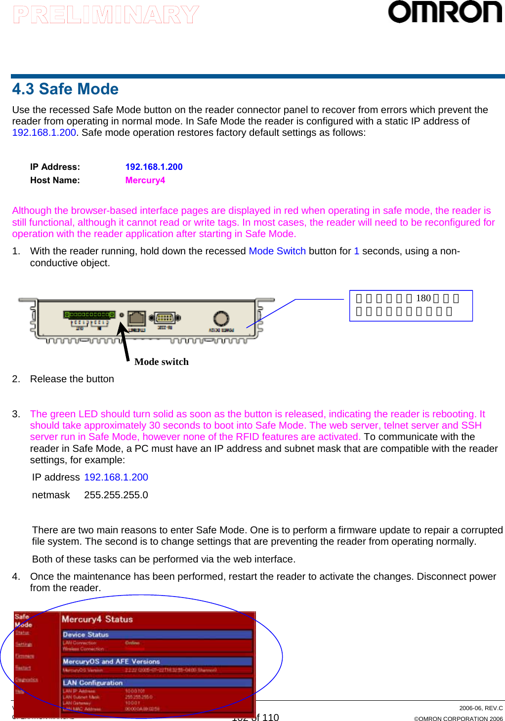
![V750 RFID READER/WRITER, ANTENNA 2006-06, REV.C OPERATION MANUAL 94 of 110 ©OMRON CORPORATION 2006 <Safe Mode 時> [Query] [Set Reader] [Utility] OMRON V740 UHF Reader/Writer <Safe Mode> [Status] Set Reader Update Help OMRON V750 UHF Reader/Writer Status [Query] Set Communication Set Operation Set Reader Utility Update Help OMRON V750 UHF Reader/Writer Status Query [Set Communication] Set Operation Set Reader Utility Update Help OMRON V750 UHF Reader/Writer Status Query Set Communication Set Operation Set Reader [Utility] Update Help OMRON V750 UHF Reader/Writer Status Query Set Communication Set Operation Set Reader Utility [Update] Help OMRON V750 UHF Reader/Writer Status Query Set Communication Set Operation Set Reader Utility Update [Help] [Update] [Help] [Status] オフライン機能 [Set Communication] [Set Operation]](https://usermanual.wiki/Omron-RFID-Business-Development-Department/V750-BA50C04/User-Guide-714521-Page-94.png)
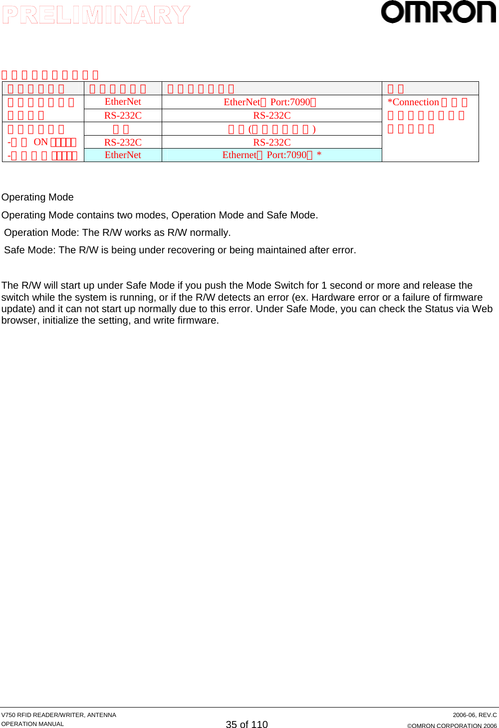
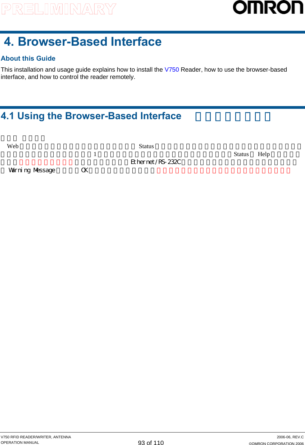
![V750 RFID READER/WRITER, ANTENNA 2006-06, REV.C OPERATION MANUAL 95 of 110 ©OMRON CORPORATION 2006 4.2 Web Operation (1) Status 画面 ブラウザでリーダにアクセスした場合、最初に表示される。 ①[Static Status(静的情報)] リーダ起動後に変更されない状態情報を表示する。 ・リーダ形式 :V740-BC50C04-US ・バージョン :XXXX-XXXX-XXXX-X(SH ソフト - MB ソフト - ロジック - H/W レベル) ・製造番号 :出荷時に書き込んだ製造管理番号 ・MAC アドレス :リーダの MAC アドレス ・[EPC コード] :リーダ自身の EPC コード(コード取得時に対応) ・アンテナ接続状態 :起動時に接続を認識したアンテナ ②[Dynamic Status(動的情報)] 刻々と変化するリーダの状態情報をリアルタイムで表示する。 ・Ethernet 状態 :コマンド I/FPort のConnection Method/Connection 有無 ・実行中のコマンド :起動元、実行コマンド、状態/結果 ・[時刻] :現在時刻 hh:mm:ss [NTP サーバー対応時] ・起動後経過時間 :起動後経過時間 hh:mm:ss Static Status Dynamic Status](https://usermanual.wiki/Omron-RFID-Business-Development-Department/V750-BA50C04/User-Guide-714521-Page-95.png)
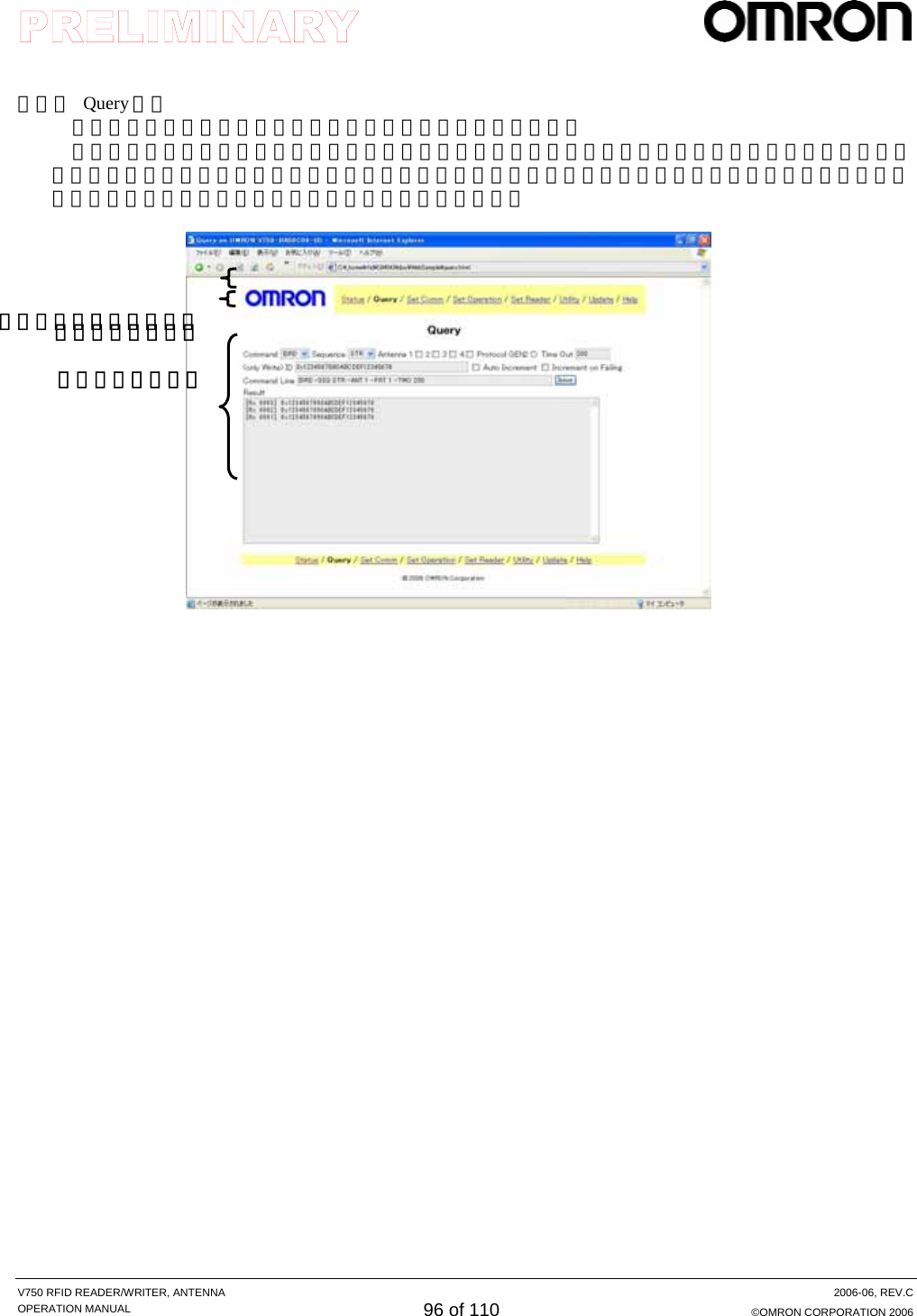
、Host、Domain、DHCP、IP Address、Net Mask、Gateway、[DNS Server]、[Connection Method]、[Default Host/Port]、[NTP Server]、[SNMP Server] ・RS-232C 設定 :[機能] (機能拡張時に対応※)、ボーレート、データ構成、[RS/CS 制御有無](機能拡張時に対応) ※RS-232C 接続の拡張 I/O 対応など、システム I/F 以外に使用する場合 ・[制御ポート] :機能[スキャン接続、アンテナ切替機、など](機能拡張時に対応) 設定反映ボタン 設定項目 設定ファイル指定 リセットボタン](https://usermanual.wiki/Omron-RFID-Business-Development-Department/V750-BA50C04/User-Guide-714521-Page-97.png)
、実行コマンド列 ※信号立上り時に以外の起動条件に対応した場合 ・出力1∼4動作 :機能−なし(ユーザ)/状態出力/交信結果判断出力、出力時間、条件 (出力時間と条件は機能を交信結果判断出力時に有効) 設定反映ボタン 設定項目](https://usermanual.wiki/Omron-RFID-Business-Development-Department/V750-BA50C04/User-Guide-714521-Page-98.png)
![V750 RFID READER/WRITER, ANTENNA 2006-06, REV.C OPERATION MANUAL 99 of 110 ©OMRON CORPORATION 2006 (5) Set Communication 画面 タグとの交信設定条件を表示、設定変更する。 ・Smoothing 機能 :2度読み防止機能、不在レスポンス省略 ・Filtering 機能 :有効/無効、Filtering 条件1−[タグ種類※]/パラメータ(MemBank、Pointer、Length、Data) ※Gen2 以外のタグの Filtering 機能に対応する場合 ・RF 制御条件 :使用 Session、アンテナ出力レベル、交信実行モード、[LBT 使用]、、[ライトベリファイ有無] 一斉に設定変更する場合は、所定のフォーマットで項目とその値を記述したファイルをアップロードすることで、反映させることができる。 各項目の値を記入し、[設定反映ボタン]を押すと、設定が変更される。 [リセットボタン]を押すと、設定値がすべてデフォルト状態に戻される。 設定反映ボタン 設定項目 設定ファイル指定 リセットボタン](https://usermanual.wiki/Omron-RFID-Business-Development-Department/V750-BA50C04/User-Guide-714521-Page-99.png)
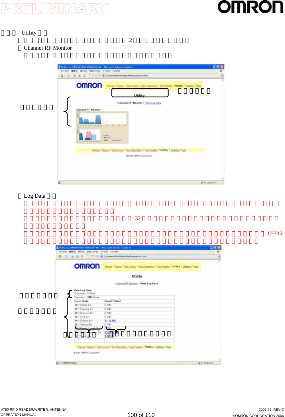
![V750 RFID READER/WRITER, ANTENNA 2006-06, REV.C OPERATION MANUAL 101 of 110 ©OMRON CORPORATION 2006 (7) Update 画面 ファームウェアのアップグレード時に、ファームウェアファイルを指定して[更新指示]ボタンを押すことによりファームウェアを更新する。 (8) Help 画面 各画面の操作方法、コマンドオプションの意味などを説明する。 ファームウェアファイル指定更新指示](https://usermanual.wiki/Omron-RFID-Business-Development-Department/V750-BA50C04/User-Guide-714521-Page-101.png)