Omron 6CYAIDV7000100 RF-ID System User Manual V700HMD11 Manual 2000 7
Omron Corporation RF-ID System V700HMD11 Manual 2000 7
UserManual.wiki
>
Omron
>
6CYAIDV7000100 User Manual
>
Manual HMD11
Contents
1.
Manual HMC71 and 73
2.
Manual HMD11
Manual HMD11
Navigation menu
Upload a User Manual
Namespaces
Wiki Guide
HTML
PDF
Info
Views
User Manual
Discussion / Help
Navigation
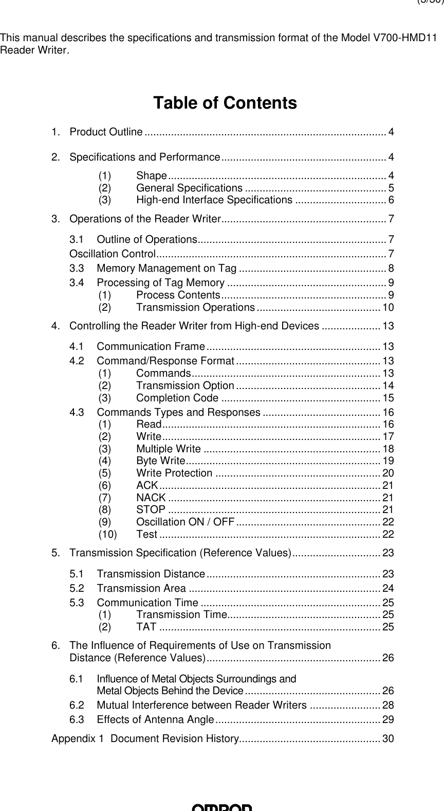
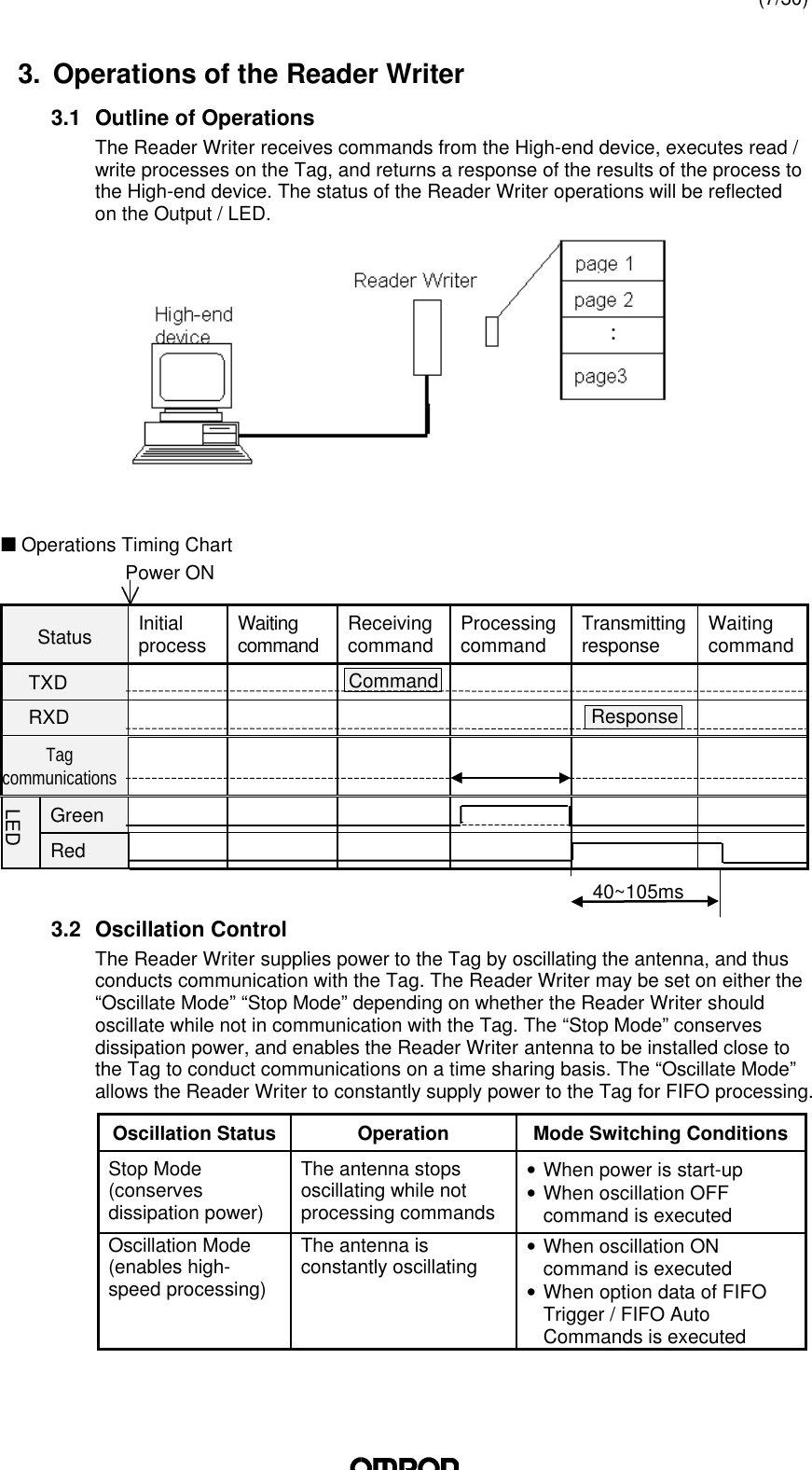

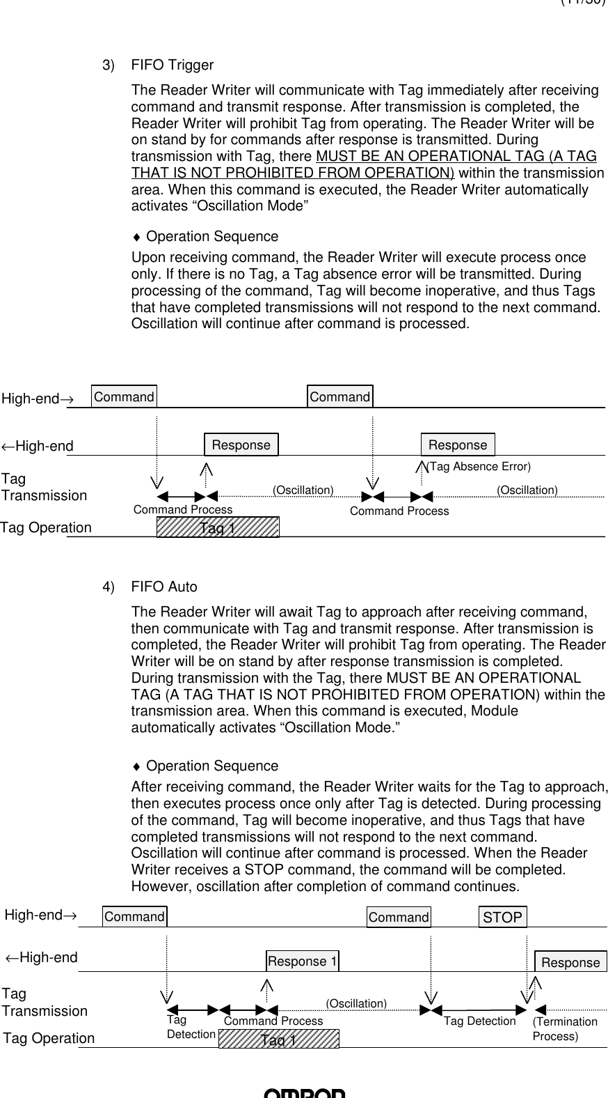
![(12/30)5) FIFO ContinueAfter waiting for the Tag to approach, then communicates with the Tagand transmits a response. After transmission is completed, Tag willbecome inoperative. After transmitting a response, the Reader Writer willawait Tag to approach again if it receives [ACK], and CONTINUE UNTILTHE READER WRITER RECEIVES A STOP COMMAND. Whencommunicating with the Tag, THERE MUST BE ONLY ONE ACTIVE TAGwithin the transmission area.♦ Operation SequenceUpon receiving the command, the Reader Writer awaits Tag to approach.When Tag is detected, the Reader Writer executes command andtransmits a response. Afterwards, when [ACK] is received, the ReaderWriter repeats the same operation. Once process is executed on a Tag,the Tag becomes inoperative, and thus a Tag will only be processed once.When the Reader Writer receives a STOP command, processing will stop.6) FIFO RepeatAfter waiting for the Tag to approach, then the Reader Writercommunicates with the Tag and transmits a response. After transmissionis completed, Tag will become inoperative. THE READER WRITER WILLCONTINUE PROCESS UNTIL IT RECEIVES A STOP COMMAND. Whencommunicating with the Tag, THERE MUST BE ONLY ONE ACTIVE TAG(A TAG THAT IS NOT PROHIBITED FROM OPERATION) within thetransmission area.♦ Operation SequenceUpon receiving the command, the Reader Writer awaits Tag to approach.When Tag is detected, the Reader Writer executes command andtransmits a response. Afterwards, the Reader Writer repeats the sameoperation. Once process is executed on a Tag, the Tag becomesinoperative, and thus a Tag will only be processed once. When theReader Writer receives a STOP command, processing will stop.TagDetectionTagDetectionTagDetectionTagDetectionSTOPCommandResponse 3ResponsResponse 2(TerminationProcess)Command ProcessCommandCommandResponse 1Tag 3Tag 2Tag 1TagTransmissionTag Operation←High-endHigh-end→(Oscillation)Tag 2Tag 1Command STOPNACKACKResponse 2Response 2Response 1TagDetectionTagDetectionTagTransmissionTag Operation←High-endHigh-end→Command ProcessCommand Process(Oscillation)](https://usermanual.wiki/Omron/6CYAIDV7000100.Manual-HMD11/User-Guide-109338-Page-12.png)
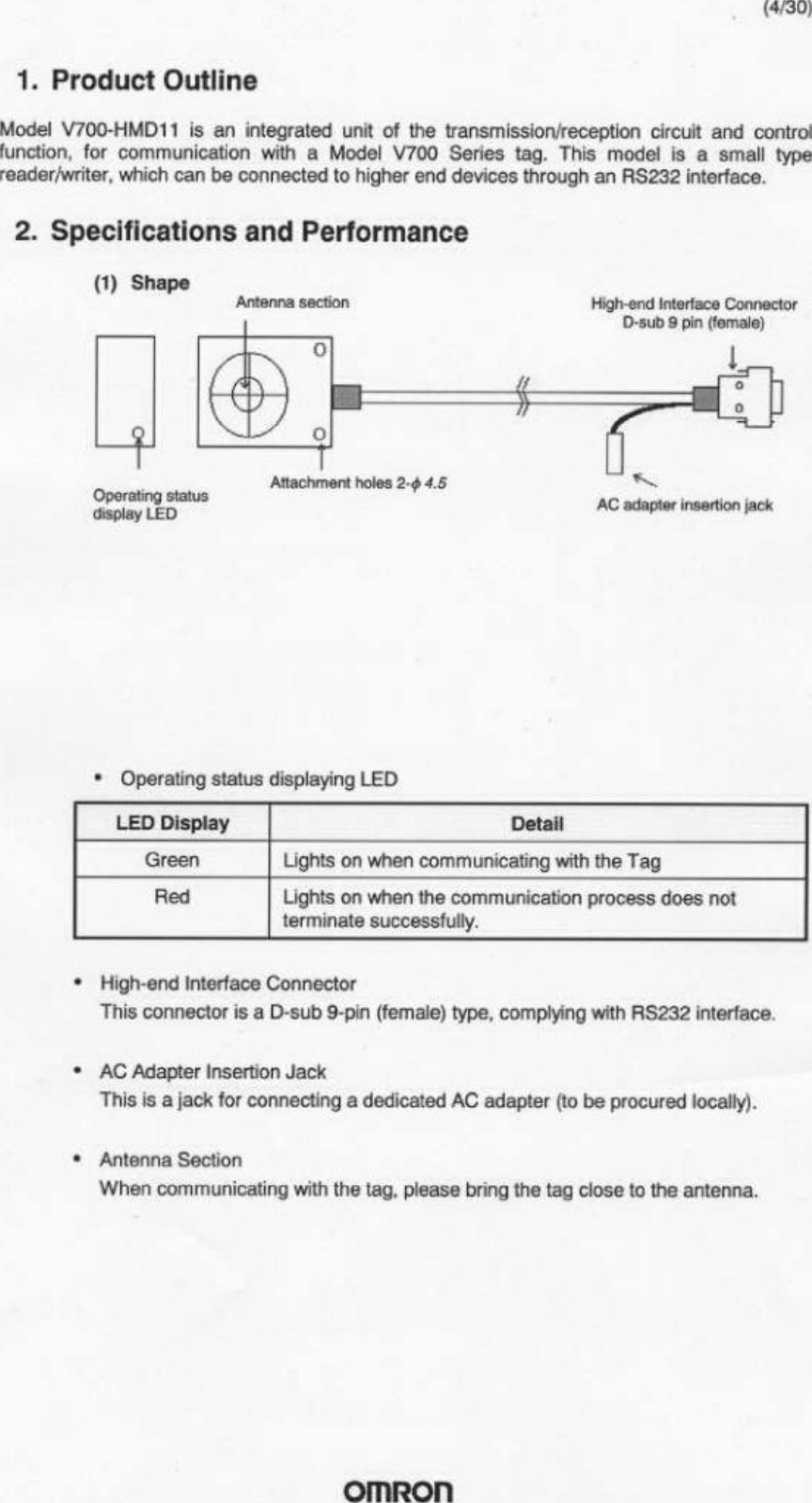
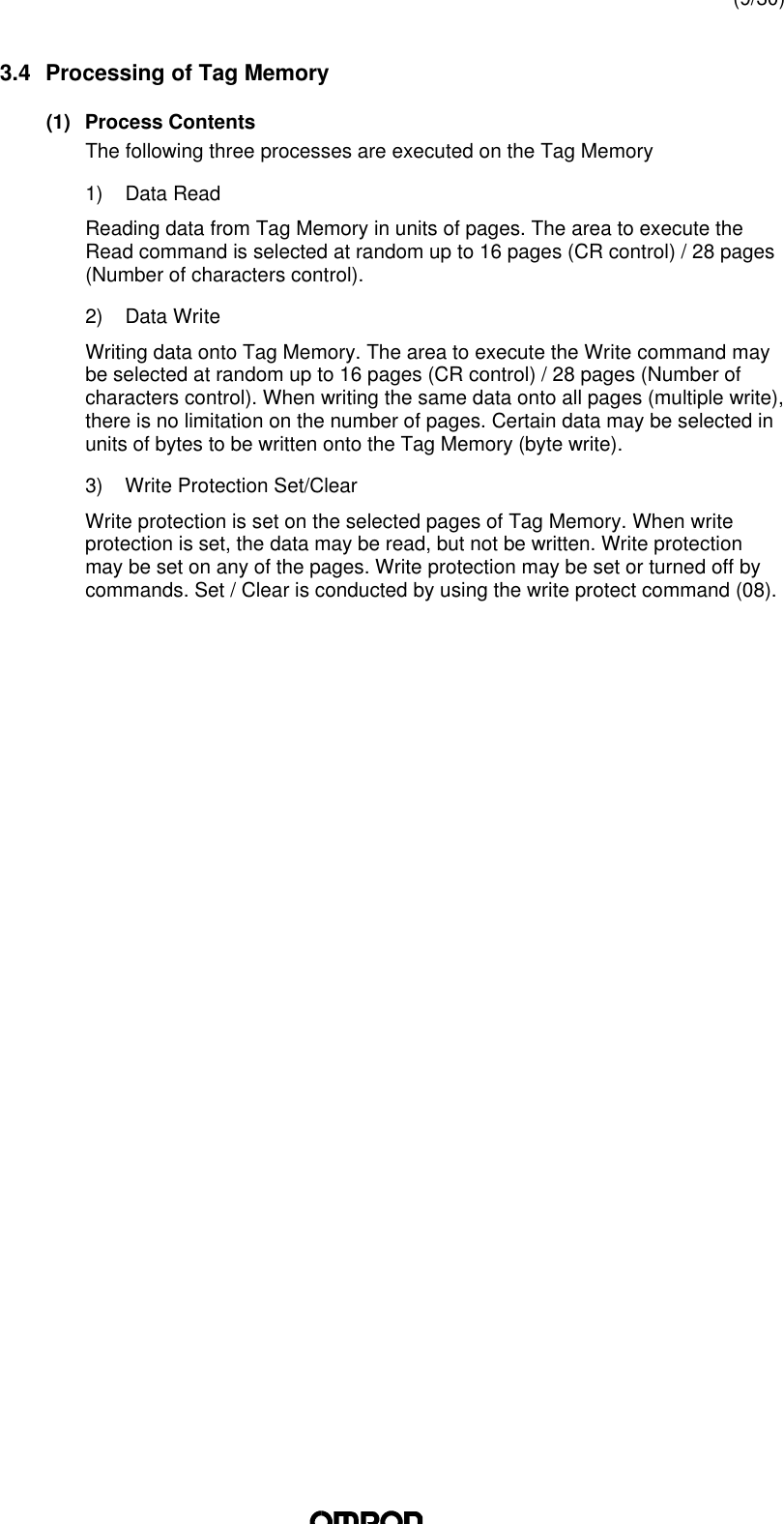
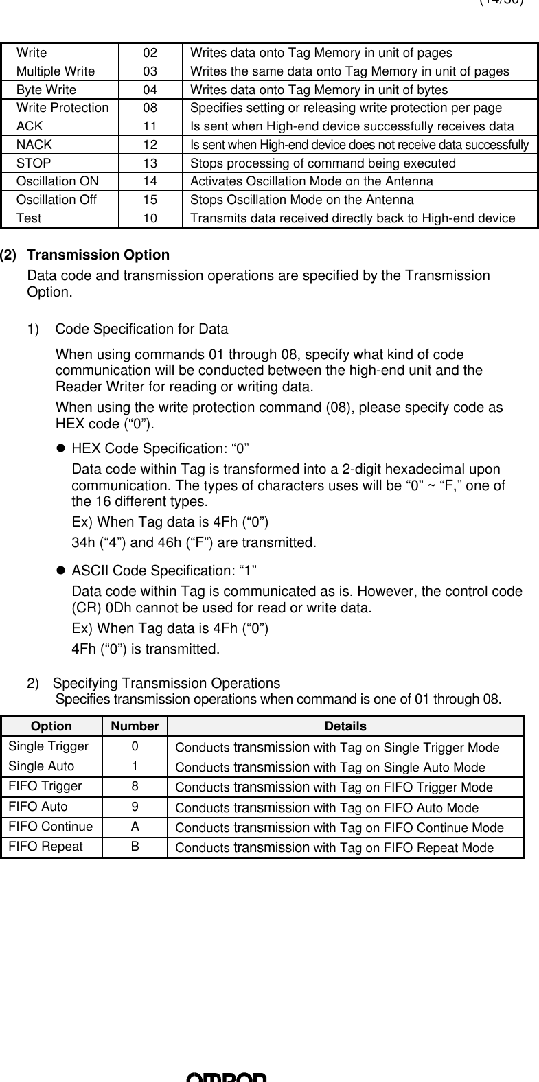
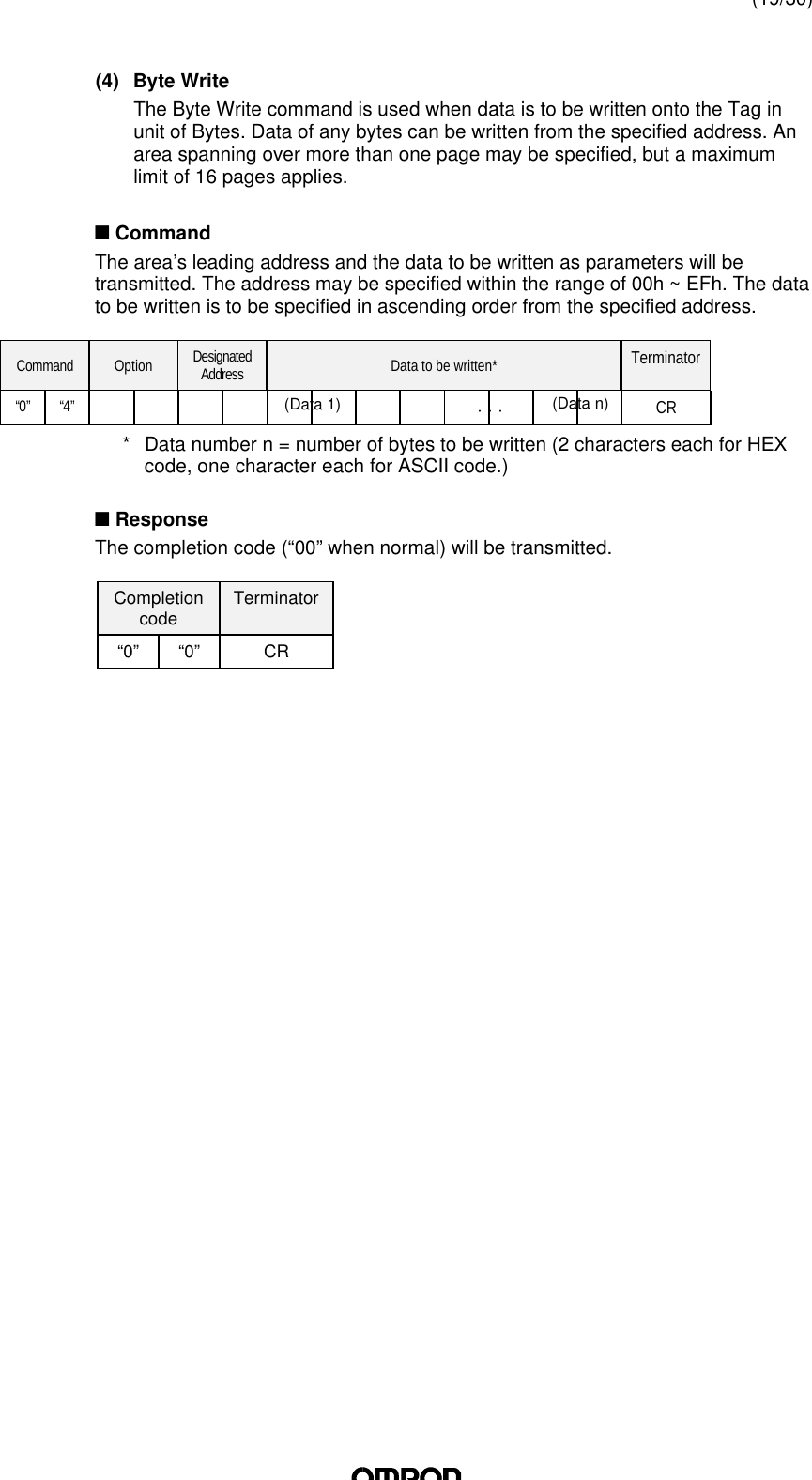
![(13/30)4. Controlling the Reader Writer from High-end Devices4.1 Communication FrameFrame format consists of 16 different types of data, “0” ~ “F,” in units of even-number characters and a terminator [CR] (ASCII Code: 0Dh). Data 1 Data 2 . . . Data n TerminatorData Number ofcharacters DetailsText 0 ~ 272 Parameters of each command (“0” ~ “F”)Terminator 1Code [CR] (0Dh) indicating the completion of transmissionframe(Communication Control Procedure)Receipt commences when a character is received first, and when [CR] is received,the frame is recognised as finished. If the interval between data exceeds 2 seconds,a transmission error will be detected. A frame error completion code (error code:18) is sent as a response to the high-end device from the Reader Writer.4.2 Command/Response Formatn CommandThe communication frame consists of command, transmission option, andparameters. The transmission option can only be attached to commands 01 ~ 08.Command Transmissionoption Parameter 1 . . . Parameter n TerminatorCRn ResponseThe communication frame consists of a completion code, parameters and aterminator.Terminationcode Parameter 1 . . . Parameter n TerminatorCR(1) CommandsSpecifies the process of the Reader Writer. The following commands areavailable.Command Name Number DescriptionRead 01 Reads Tag Memory data in unit of pagesData section: within 272 characters (in even numbers)TransmissionData code specification](https://usermanual.wiki/Omron/6CYAIDV7000100.Manual-HMD11/User-Guide-109338-Page-13.png)
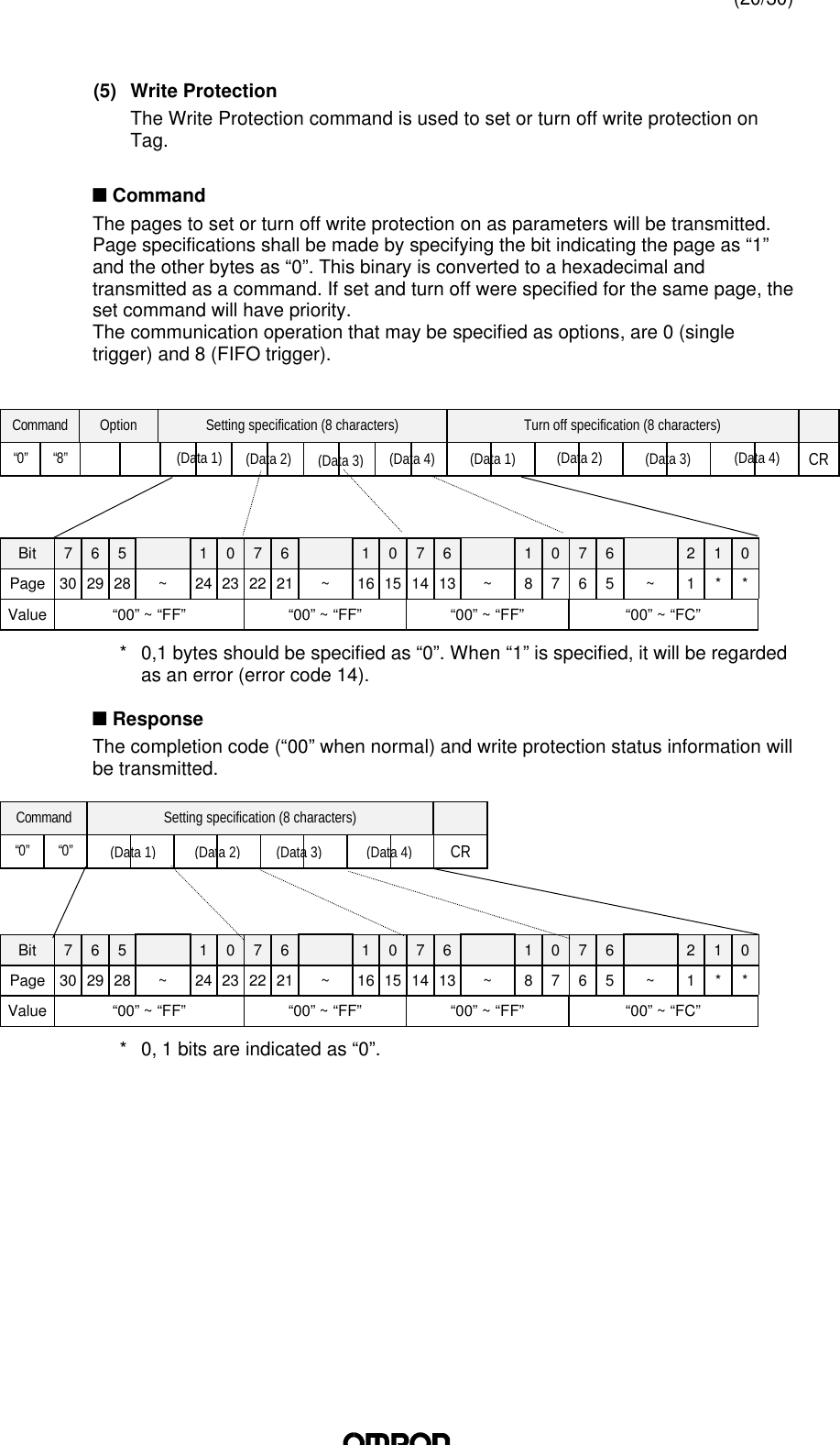
(Data n)⋅ ⋅ ⋅(Data 1)](https://usermanual.wiki/Omron/6CYAIDV7000100.Manual-HMD11/User-Guide-109338-Page-16.png)
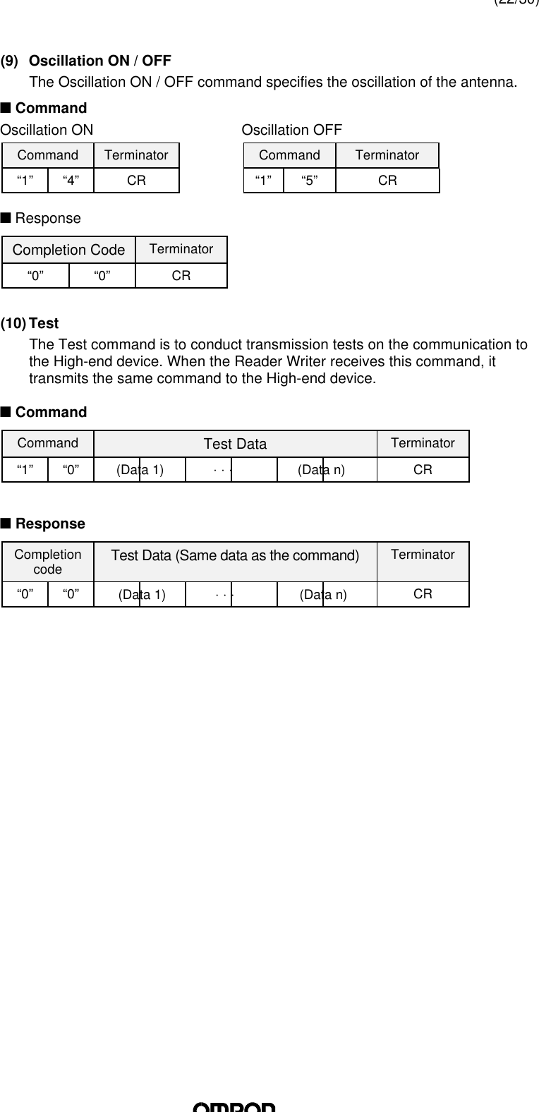
(Data n)⋅ ⋅ ⋅(Data 1)](https://usermanual.wiki/Omron/6CYAIDV7000100.Manual-HMD11/User-Guide-109338-Page-17.png)


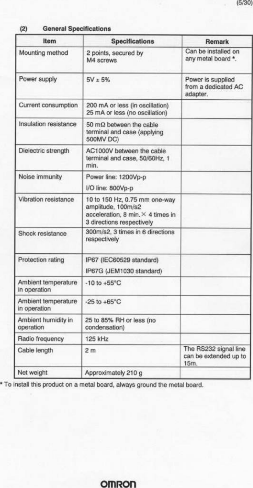
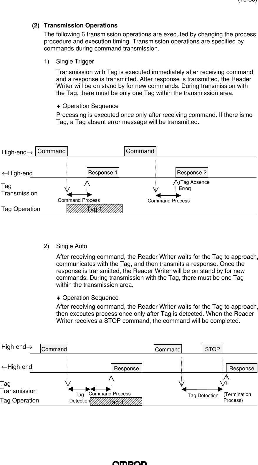
![(25/30)5.3 Communication TimeThe Model V700 Series has two communication times: the transmission time andthe TAT (Turn Around Time).(1) Transmission TimeThis is the transmission processing time between the Reader Writer and theTags. This time varies in accordance with the number of pages to be read /written.The transmission time values are as indicated below. This value is estimatedbased on the assumption that the transmission operation is on trigger modeand that there is no interference in transmission due to noise and other causes.(2) TATThis is the time required for the high-end unit to transmit a command to the ReaderWriter, and to complete receipt of a response. This time varies in accordance withthe transmission speed and the communication control mode.<Example of TAT Calculation>• Read 1 page(bit time) (number of bits per character) (number of characters transmitted)Prerequisites: 1HEX code specification2No spaces between characters; all data sent consecutivelyTotal pages processedTransmission Time(ms)WriteReadCommand ResponseTATTransmission timeTransmission Time Calculation FormulaTransmission Time (msec)Read T=48N+66Write T=55N+120N: pages to be processedCommand010000000004[CR]Transmission time Response001234567890ABCDEF[CR]( ) ( ) ( ) ( ) ( ) ( ) ( ) ( )sec1511911sec96001sec1141311sec96001mcharactersbitsmcharactersbits =××++××](https://usermanual.wiki/Omron/6CYAIDV7000100.Manual-HMD11/User-Guide-109338-Page-25.png)