Omron 6CYAIDV7000100 RF-ID System User Manual V700HMD11 Manual 2000 7
Omron Corporation RF-ID System V700HMD11 Manual 2000 7
Omron >
Contents
- 1. Manual HMC71 and 73
- 2. Manual HMD11
Manual HMD11
(1/30)
V700 RFID System
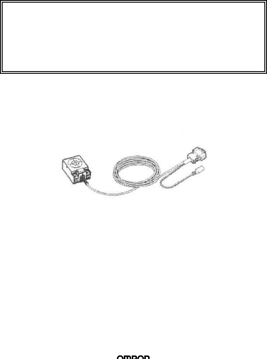
Model V700-HMD11 Reader Writer
Operation Manual
Issued: July 7, 2000

(2/30)
Applicable Standards
FCC (USA) Part 15 subpart B and C
FCC NOTICE
This equipment has been tested and found to comply with the limits for a Class B digital
device, pursuant to part 15 of the FCC Rules. These limits are designed to provide
reasonable protection against harmful interference in a residential installation.
This equipment generates, uses and can radiate radio frequency energy and, if not installed
and used in accordance with the instructions, may cause harmful interference to radio
communications. However, there is no guarantee that interference will not occur in a
particular installation. If this equipment dose cause harmful interference to radio or television
reception, which can be determined by turning the equipment off and on, the user is
encouraged to try to correct the interference by one or more of the following measures:
-Reorient or relocate the receiving antenna.
-Increase the separation between the equipment and receiver.
-Connect the equipment into an outlet on a circuit different from that to which the receiver is
connected.
-Consult the dealer or an experienced radio / TV technician for help.
FCC WARNING
Changes or modifications not expressly approved by the party responsible for compliance
could void the user’s authority to operate the equipment.
Properly shielded an grounded cables and connectors must be used for connection to host
computer and / or peripherals in order to meet FCC emission limits.
AC adapter with ferrite core must be used for RF interference suppression.
Precautions of Use
This device uses a frequency of 125 kHz to communicate with a tag. Some transceivers,
motors, monitor units, and power supply (power IC) emit noise that adversely affects this
communication with the tag. If this product is to be used in an environment close to such
devices, please check the effects from these devices prior to use.
To minimise the effect of noise, please ground any metal object surrounding this device.

(3/30)
This manual describes the specifications and transmission format of the Model V700-HMD11
Reader Writer.
Table of Contents
1. Product Outline.................................................................................. 4
2. Specifications and Performance........................................................ 4
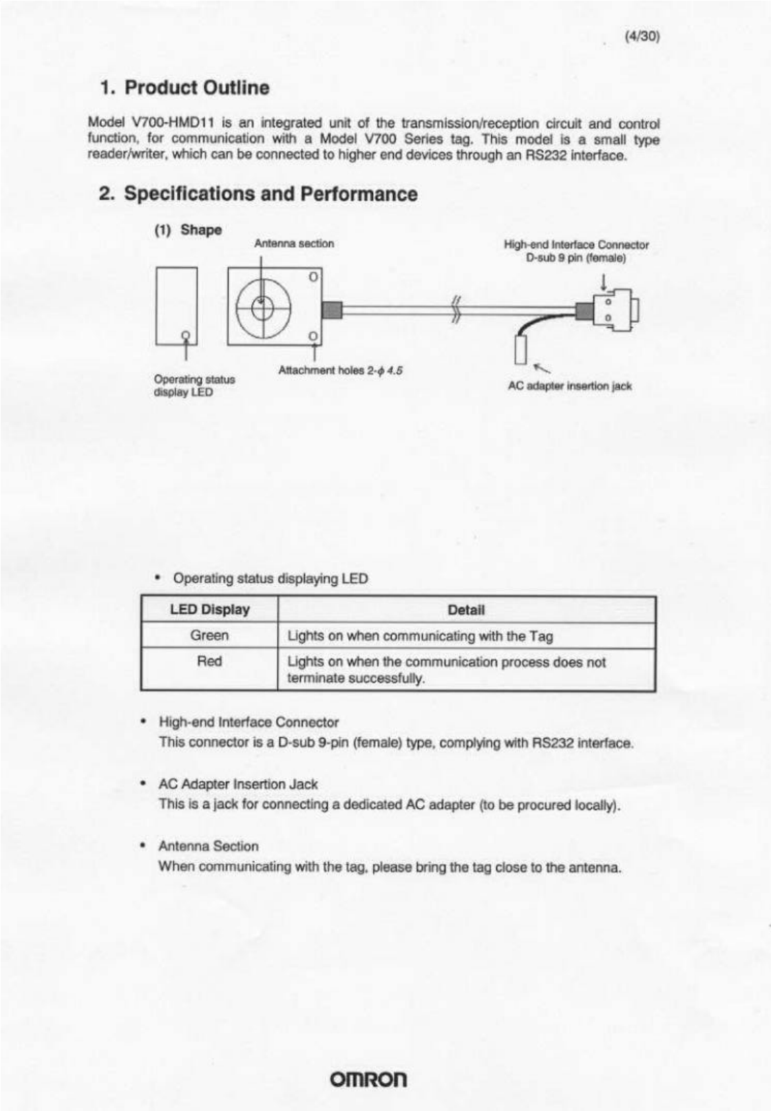
(1) Shape.......................................................................... 4
(2) General Specifications ................................................ 5
(3) High-end Interface Specifications ............................... 6
3. Operations of the Reader Writer........................................................ 7
3.1 Outline of Operations................................................................ 7
Oscillation Control.............................................................................. 7
3.3 Memory Management on Tag .................................................. 8
3.4 Processing of Tag Memory ...................................................... 9
(1) Process Contents........................................................ 9
(2) Transmission Operations.......................................... 10
4. Controlling the Reader Writer from High-end Devices .................... 13
4.1 Communication Frame........................................................... 13
4.2 Command/Response Format................................................. 13
(1) Commands................................................................ 13
(2) Transmission Option................................................. 14
(3) Completion Code ...................................................... 15
4.3 Commands Types and Responses ........................................ 16
(1) Read.......................................................................... 16
(2) Write.......................................................................... 17
(3) Multiple Write ............................................................ 18
(4) Byte Write.................................................................. 19
(5) Write Protection ........................................................20
(6) ACK........................................................................... 21
(7) NACK ........................................................................ 21
(8) STOP ........................................................................ 21
(9) Oscillation ON / OFF................................................. 22
(10) Test ........................................................................... 22
5. Transmission Specification (Reference Values).............................. 23
5.1 Transmission Distance........................................................... 23
5.2 Transmission Area ................................................................. 24
5.3 Communication Time ............................................................. 25
(1) Transmission Time.................................................... 25
(2) TAT ........................................................................... 25
6. The Influence of Requirements of Use on Transmission
Distance (Reference Values)........................................................... 26
6.1 Influence of Metal Objects Surroundings and
Metal Objects Behind the Device.............................................. 26
6.2 Mutual Interference between Reader Writers ........................ 28
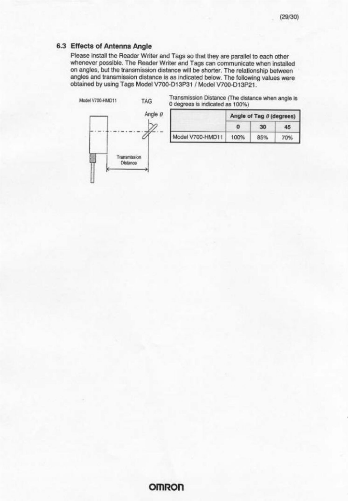
6.3 Effects of Antenna Angle........................................................ 29
Appendix 1 Document Revision History................................................ 30
(6/30)
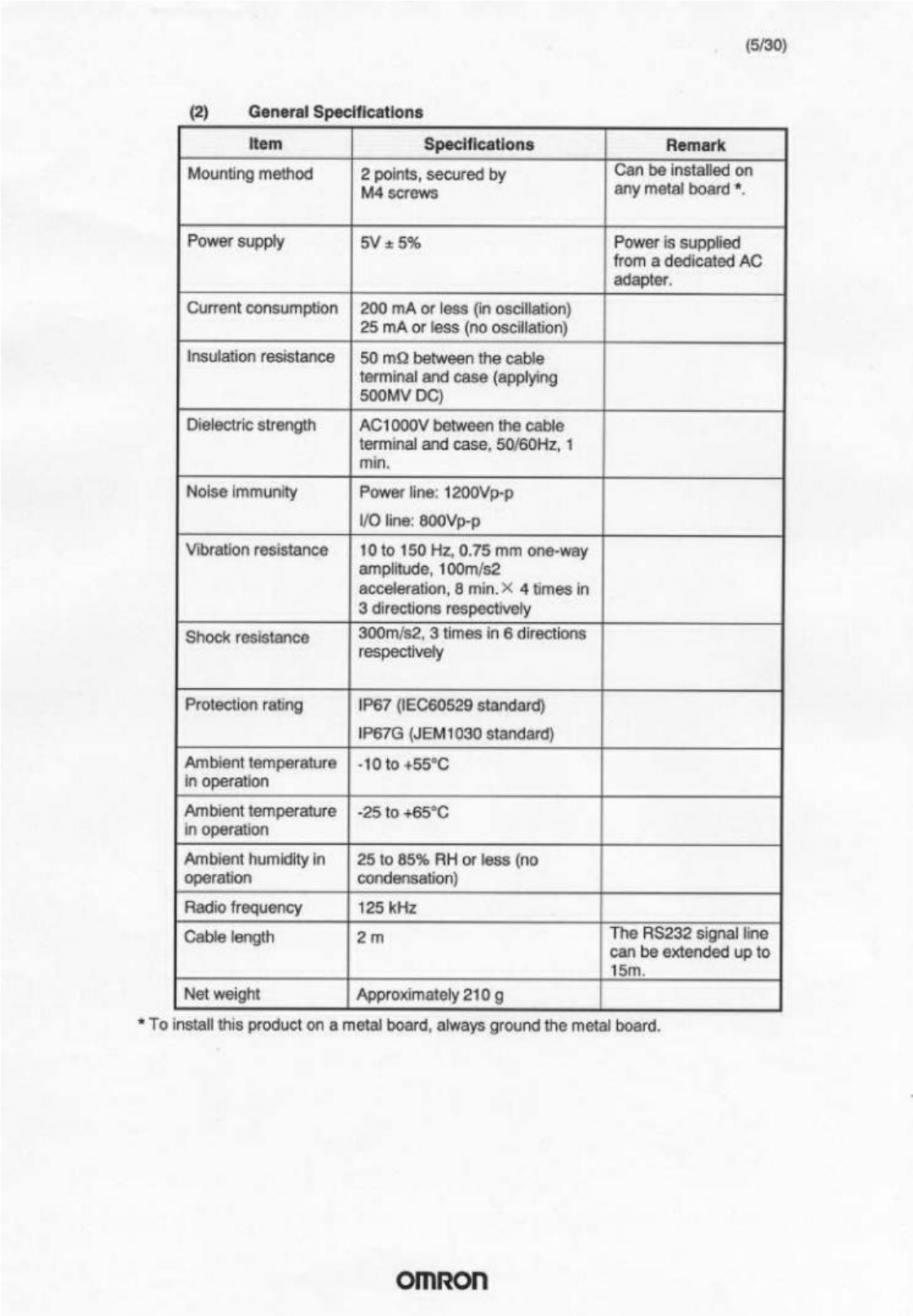
(3) High-end Interface Specifications
Item Specifications
Connector D-sub 9-pin connector, female (applies to DOS/V
machines)
Communication method RS232 compliant
Synchronisation method Asynchronous mode, start-stop synchronisation
method
Communication control
method One to one procedure
Transmission speed
(fixed) 9600 bps
Character format Start bit Data bit Parity bit Stop bit Total
(fixed) 1 8 Even 1 11
Error detection method Even parity
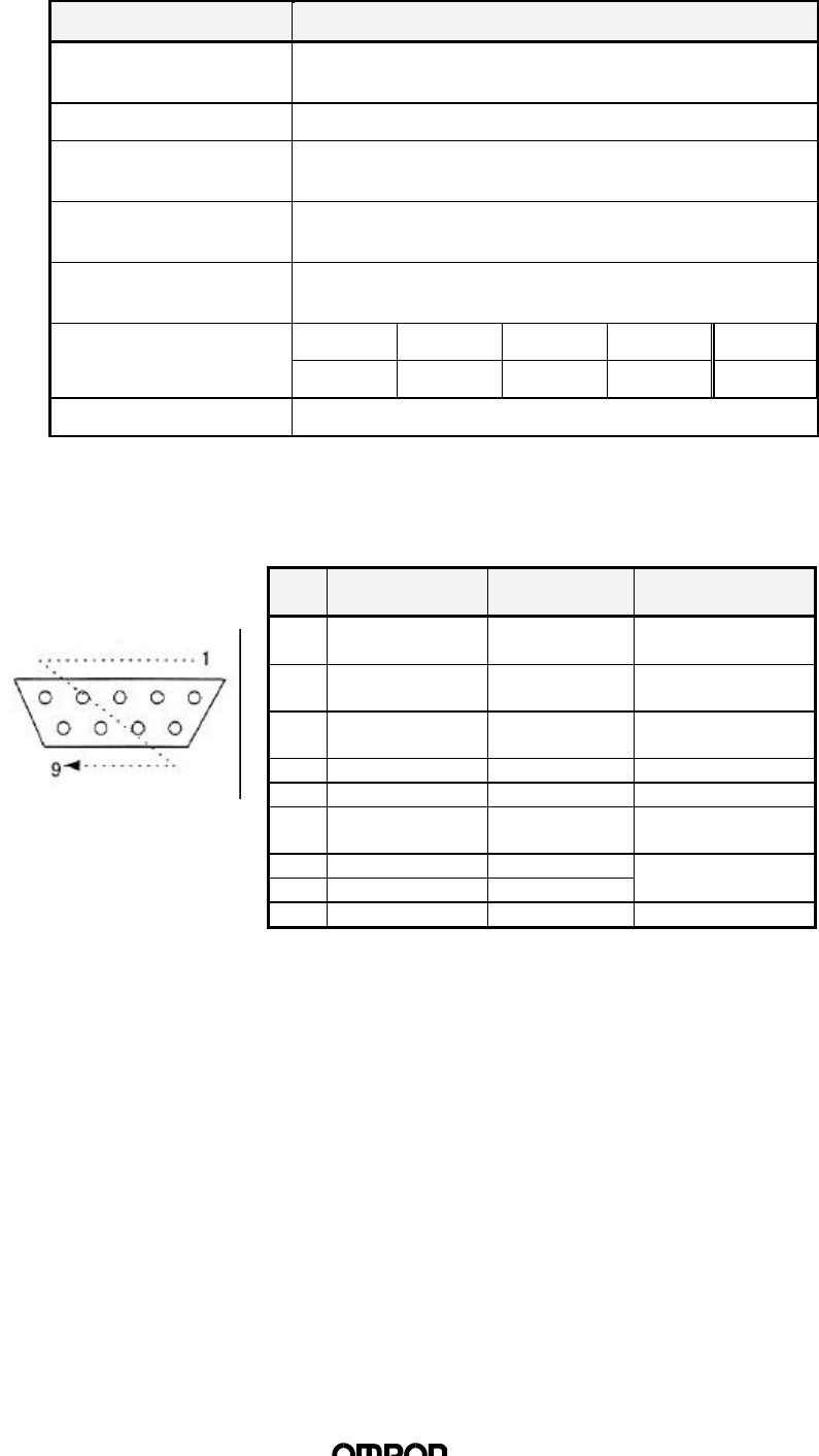
n Pin Assignment and Connection with High-end Devices
Pins are assigned for DOS/V machines.
Pin
No. Name Abbreviation Signal direction
1Carrier detection CD Connected to DR
in the connector.
2Receive data RD Upper device ß
reader/writer
3Send data SD Upper device à
reader/writer
4- - -
5Signal ground SG -
6Data set ready DR* Upper device ß
reader/writer
7Request to send RS
8Send possible CS
Looped back in the
connector.
9- - -
* DR is always ON when this product is operating.
(7/30)
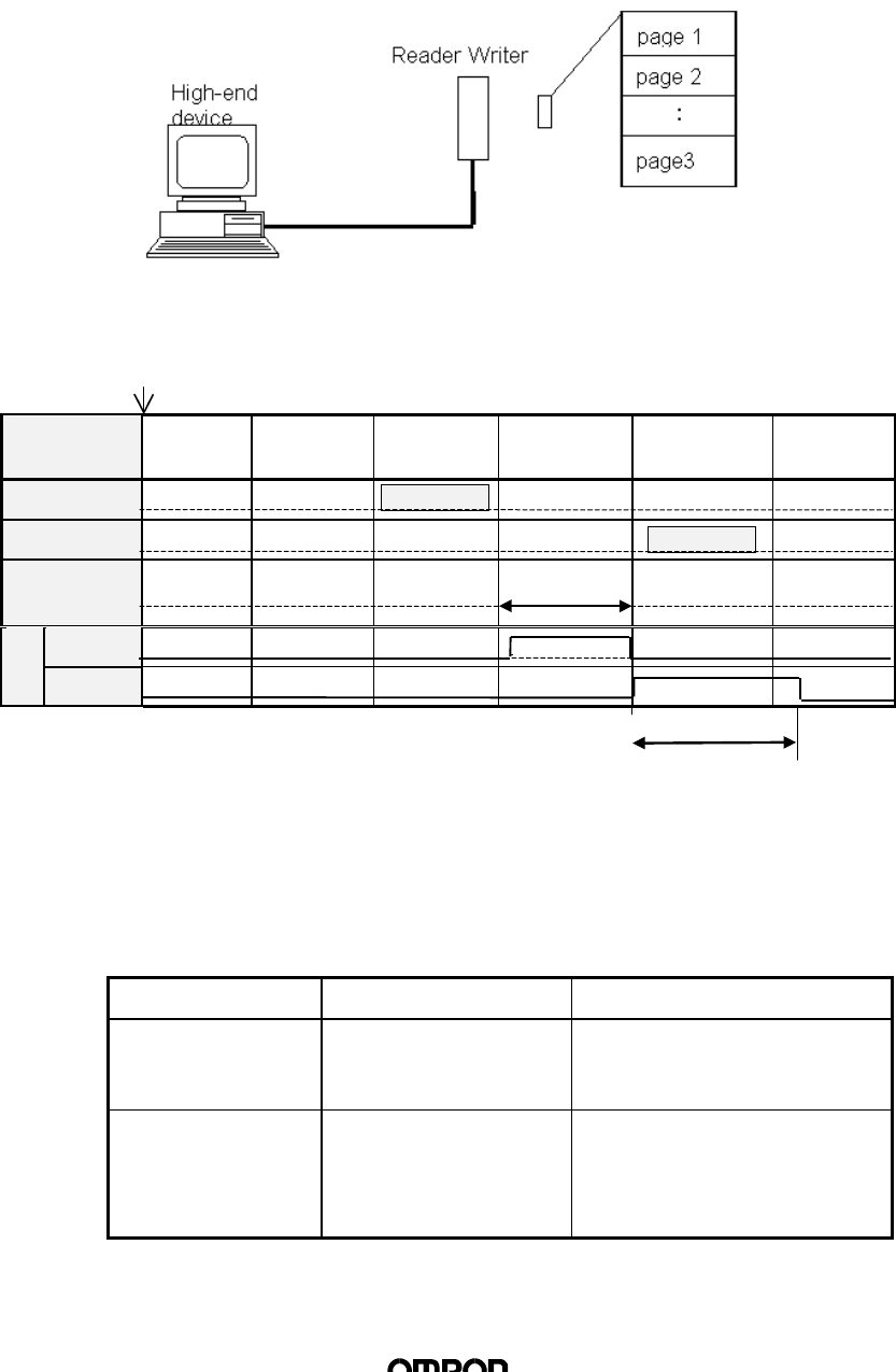
3. Operations of the Reader Writer
3.1 Outline of Operations
The Reader Writer receives commands from the High-end device, executes read /
write processes on the Tag, and returns a response of the results of the process to
the High-end device. The status of the Reader Writer operations will be reflected
on the Output / LED.
n Operations Timing Chart
Power ON
Status Initial
process Waiting
command Receiving
command Processing
command Transmitting
response Waiting
command
TXD Command
RXD Response
Tag
communications
Green
LED
Red
3.2 Oscillation Control
The Reader Writer supplies power to the Tag by oscillating the antenna, and thus
conducts communication with the Tag. The Reader Writer may be set on either the
“Oscillate Mode” “Stop Mode” depending on whether the Reader Writer should
oscillate while not in communication with the Tag. The “Stop Mode” conserves
dissipation power, and enables the Reader Writer antenna to be installed close to
the Tag to conduct communications on a time sharing basis. The “Oscillate Mode”
allows the Reader Writer to constantly supply power to the Tag for FIFO processing.
Oscillation Status Operation Mode Switching Conditions
Stop Mode
(conserves
dissipation power)
The antenna stops
oscillating while not
processing commands
• When power is start-up
• When oscillation OFF
command is executed
Oscillation Mode
(enables high-
speed processing)
The antenna is
constantly oscillating • When oscillation ON
command is executed
• When option data of FIFO
Trigger / FIFO Auto
Commands is executed
40~105ms

(8/30)
3.3 Memory Management on Tag
There are two types of the tag in the memory capacity: 128 bytes (user area 112
bytes) and 256 bytes (user area 240 bytes). The memory area recognises every 8
bytes as one page, distinguished by such addresses as 00h ~ 07h, 08h ~0Fh, and
so on.
n
Memory Map (00h ~ EFh indicates memory address)
Page 8 bytes / page
1 00h 01h 02h 03h 04h 05h 06h 07h
2 08h 09h 0Ah 0Bh 0Ch 0Dh 0Eh 0Fh
3 10h 11h 12h ⋅⋅⋅ ⋅⋅⋅ 17h
4 18h 19h 1Ah ⋅⋅⋅ ⋅⋅⋅ 1Fh
5 20h 27h
6 28h 2Fh
7 30h 37h
8
9
10 : :
11 : :
12
13
14 68h ⋅⋅⋅ ⋅⋅⋅ 6Fh
15 70h ⋅⋅⋅ ⋅⋅⋅ 77h
16 78h ⋅⋅⋅ ⋅⋅⋅ 7Fh
: : :
: : :
29 E0h E1h ⋅⋅⋅ ⋅⋅⋅ E7h
30 E8h E9h ⋅⋅⋅ ⋅⋅⋅ EFh
112 bytes
240 bytes

(9/30)
3.4 Processing of Tag Memory
(1) Process Contents
The following three processes are executed on the Tag Memory
1) Data Read
Reading data from Tag Memory in units of pages. The area to execute the
Read command is selected at random up to 16 pages (CR control) / 28 pages
(Number of characters control).
2) Data Write
Writing data onto Tag Memory. The area to execute the Write command may
be selected at random up to 16 pages (CR control) / 28 pages (Number of
characters control). When writing the same data onto all pages (multiple write),
there is no limitation on the number of pages. Certain data may be selected in
units of bytes to be written onto the Tag Memory (byte write).
3) Write Protection Set/Clear
Write protection is set on the selected pages of Tag Memory. When write
protection is set, the data may be read, but not be written. Write protection
may be set on any of the pages. Write protection may be set or turned off by
commands. Set / Clear is conducted by using the write protect command (08).
(10/30)
(2) Transmission Operations
The following 6 transmission operations are executed by changing the process
procedure and execution timing. Transmission operations are specified by
commands during command transmission.
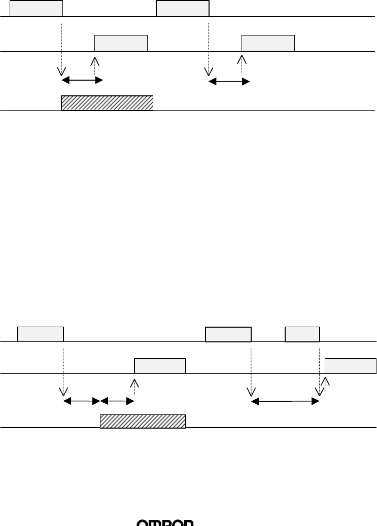
1) Single Trigger
Transmission with Tag is executed immediately after receiving command
and a response is transmitted. After response is transmitted, the Reader
Writer will be on stand by for new commands. During transmission with
the Tag, there must be only one Tag within the transmission area.
♦ Operation Sequence
Processing is executed once only after receiving command. If there is no
Tag, a Tag absent error message will be transmitted.
2) Single Auto
After receiving command, the Reader Writer waits for the Tag to approach,
communicates with the Tag, and then transmits a response. Once the
response is transmitted, the Reader Writer will be on stand by for new
commands. During transmission with the Tag, there must be one Tag
within the transmission area.
♦ Operation Sequence
After receiving command, the Reader Writer waits for the Tag to approach,
then executes process once only after Tag is detected. When the Reader
Writer receives a STOP command, the command will be completed.
Tag
Transmission
Tag 1
Tag Operation
←High-end
High-end→Command Command
Response 2
(Tag Absence
Error)
Command Process
Command Process
Response 1
Response
Tag
Transmission
Tag 1
Tag Operation
←High-end
High-end→
Command
Command
STOP
(Termination
Process)
Tag Detection
Tag
Detection
Command Process
Response
(11/30)
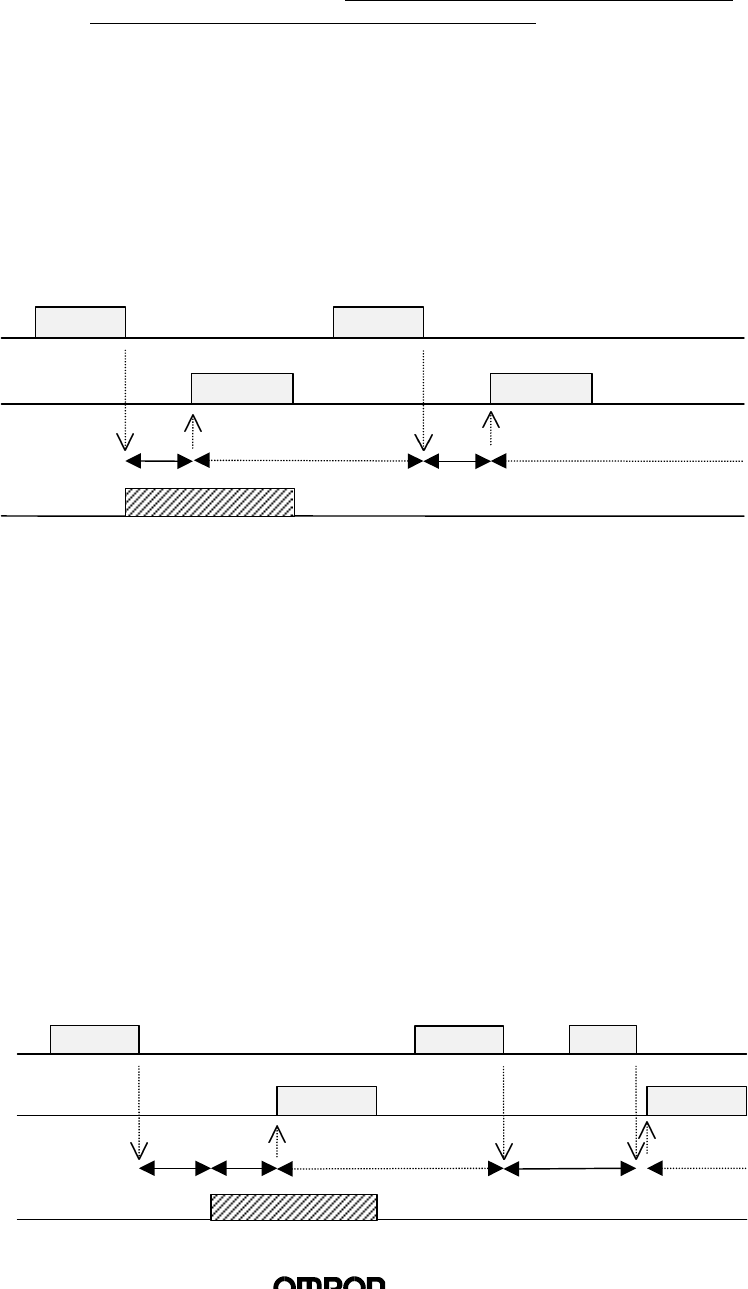
3) FIFO Trigger
The Reader Writer will communicate with Tag immediately after receiving
command and transmit response. After transmission is completed, the
Reader Writer will prohibit Tag from operating. The Reader Writer will be
on stand by for commands after response is transmitted. During
transmission with Tag, there MUST BE AN OPERATIONAL TAG (A TAG
THAT IS NOT PROHIBITED FROM OPERATION) within the transmission
area. When this command is executed, the Reader Writer automatically
activates “Oscillation Mode”
♦ Operation Sequence
Upon receiving command, the Reader Writer will execute process once
only. If there is no Tag, a Tag absence error will be transmitted. During
processing of the command, Tag will become inoperative, and thus Tags
that have completed transmissions will not respond to the next command.
Oscillation will continue after command is processed.
4) FIFO Auto
The Reader Writer will await Tag to approach after receiving command,
then communicate with Tag and transmit response. After transmission is
completed, the Reader Writer will prohibit Tag from operating. The Reader
Writer will be on stand by after response transmission is completed.
During transmission with the Tag, there MUST BE AN OPERATIONAL
TAG (A TAG THAT IS NOT PROHIBITED FROM OPERATION) within the
transmission area. When this command is executed, Module
automatically activates “Oscillation Mode.”
♦ Operation Sequence
After receiving command, the Reader Writer waits for the Tag to approach,
then executes process once only after Tag is detected. During processing
of the command, Tag will become inoperative, and thus Tags that have
completed transmissions will not respond to the next command.
Oscillation will continue after command is processed. When the Reader
Writer receives a STOP command, the command will be completed.
However, oscillation after completion of command continues.
(Oscillation)
Tag 1
Command Command
Response
STOP
Response 1
1
Tag
Transmission
Tag Operation
←High-end
High-end→
Tag Detection
Tag
Detection
Command Process
(Termination
Process)
Tag 1
Tag
Transmission
Tag Operation
←High-end
High-end→
Command Command
(Tag Absence Error)
Command Process
Command Process
(Oscillation)
(Oscillation)
ResponseResponse
(12/30)
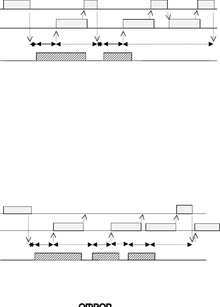
5) FIFO Continue
After waiting for the Tag to approach, then communicates with the Tag
and transmits a response. After transmission is completed, Tag will
become inoperative. After transmitting a response, the Reader Writer will
await Tag to approach again if it receives [ACK], and CONTINUE UNTIL
THE READER WRITER RECEIVES A STOP COMMAND. When
communicating with the Tag, THERE MUST BE ONLY ONE ACTIVE TAG
within the transmission area.
♦ Operation Sequence
Upon receiving the command, the Reader Writer awaits Tag to approach.
When Tag is detected, the Reader Writer executes command and
transmits a response. Afterwards, when [ACK] is received, the Reader
Writer repeats the same operation. Once process is executed on a Tag,
the Tag becomes inoperative, and thus a Tag will only be processed once.
When the Reader Writer receives a STOP command, processing will stop.
6) FIFO Repeat
After waiting for the Tag to approach, then the Reader Writer
communicates with the Tag and transmits a response. After transmission
is completed, Tag will become inoperative. THE READER WRITER WILL
CONTINUE PROCESS UNTIL IT RECEIVES A STOP COMMAND. When
communicating with the Tag, THERE MUST BE ONLY ONE ACTIVE TAG
(A TAG THAT IS NOT PROHIBITED FROM OPERATION) within the
transmission area.
♦ Operation Sequence
Upon receiving the command, the Reader Writer awaits Tag to approach.
When Tag is detected, the Reader Writer executes command and
transmits a response. Afterwards, the Reader Writer repeats the same
operation. Once process is executed on a Tag, the Tag becomes
inoperative, and thus a Tag will only be processed once. When the
Reader Writer receives a STOP command, processing will stop.
Tag
Detection
Tag
Detection
Tag
Detection
Tag
Detection
STOP
Command
Response 3
Respons
Response 2
(Termination
Process)
Command Process
Command
Command
Response 1
Tag 3
Tag 2
Tag 1
Tag
Transmission
Tag Operation
←High-end
High-end→
(Oscillation)
Tag 2
Tag 1
Command STOPNACKACK
Response 2Response 2Response 1
Tag
Detection
Tag
Detection
Tag
Transmission
Tag Operation
←High-end
High-end→
Command Process
Command Process
(Oscillation)
(13/30)
4. Controlling the Reader Writer from High-end Devices
4.1 Communication Frame
Frame format consists of 16 different types of data, “0” ~ “F,” in units of even-
number characters and a terminator [CR] (ASCII Code: 0Dh).
Data 1 Data 2 . . . Data n Terminator
Data Number of
characters Details
Text 0 ~ 272 Parameters of each command (“0” ~ “F”)
Terminator 1Code [CR] (0Dh) indicating the completion of transmission
frame
(Communication Control Procedure)
Receipt commences when a character is received first, and when [CR] is received,
the frame is recognised as finished. If the interval between data exceeds 2 seconds,
a transmission error will be detected. A frame error completion code (error code:
18) is sent as a response to the high-end device from the Reader Writer.
4.2 Command/Response Format
n
Command
The communication frame consists of command, transmission option, and
parameters. The transmission option can only be attached to commands 01 ~ 08.
Command Transmission
option Parameter 1 . . . Parameter n Terminator
CR
n
Response
The communication frame consists of a completion code, parameters and a
terminator.
Termination
code Parameter 1 . . . Parameter n Terminator
CR
(1) Commands
Specifies the process of the Reader Writer. The following commands are
available.
Command Name Number Description
Read 01 Reads Tag Memory data in unit of pages
Data section: within 272 characters (in even numbers)
Transmission
Data code specification

(14/30)
Write 02 Writes data onto Tag Memory in unit of pages
Multiple Write 03 Writes the same data onto Tag Memory in unit of pages
Byte Write 04 Writes data onto Tag Memory in unit of bytes
Write Protection 08 Specifies setting or releasing write protection per page
ACK 11 Is sent when High-end device successfully receives data
NACK 12 Is sent when High-end device does not receive data successfully
STOP 13 Stops processing of command being executed
Oscillation ON 14 Activates Oscillation Mode on the Antenna
Oscillation Off 15 Stops Oscillation Mode on the Antenna
Test 10 Transmits data received directly back to High-end device
(2) Transmission Option
Data code and transmission operations are specified by the Transmission
Option.
1) Code Specification for Data
When using commands 01 through 08, specify what kind of code
communication will be conducted between the high-end unit and the
Reader Writer for reading or writing data.
When using the write protection command (08), please specify code as
HEX code (“0”).
l HEX Code Specification: “0”
Data code within Tag is transformed into a 2-digit hexadecimal upon
communication. The types of characters uses will be “0” ~ “F,” one of
the 16 different types.
Ex) When Tag data is 4Fh (“0”)
34h (“4”) and 46h (“F”) are transmitted.
l ASCII Code Specification: “1”
Data code within Tag is communicated as is. However, the control code
(CR) 0Dh cannot be used for read or write data.
Ex) When Tag data is 4Fh (“0”)
4Fh (“0”) is transmitted.
2) Specifying Transmission Operations
Specifies transmission operations when command is one of 01 through 08.
Option Number Details
Single Trigger 0Conducts transmission with Tag on Single Trigger Mode
Single Auto 1Conducts transmission with Tag on Single Auto Mode
FIFO Trigger 8Conducts transmission with Tag on FIFO Trigger Mode
FIFO Auto 9Conducts transmission with Tag on FIFO Auto Mode
FIFO Continue AConducts transmission with Tag on FIFO Continue Mode
FIFO Repeat BConducts transmission with Tag on FIFO Repeat Mode

(15/30)
(3) Completion Code
The Reader Writer will return the response to the high-end unit by transmitting
a completion code. The definitions of the completion codes are as follows:
Class Completion
Code Name Details
Normal end 00 Normal end Normal operations completed.
10 Parity error ∗ There is a parity error in the command
received.
11 Framing error There is a framing error in the command
received.
12 Overrun error There is an overrun error in the command
received.
14 Format error The command format is not suitable for the
specification.
Ex) Command section is not defined;
page/address specification is incorrect, etc.
Communication
Error between
high-end unit
and Reader
Writer
18 Frame length error When the receiving frame exceeds 273
characters.
When the intervals between the characters
being received exceeded 2 sec.
70 Transmission error Noise or other disruption occurred during
communication with Tag, and the command
cannot be executed properly.
71 Verification error Tag is dated or incapable of being written
correctly for physical reasons.
72 Tag absence error Tag is not present near antenna at time of
Trigger commands execution.
7A Address
specification error Page specification is incorrect.
7B Outside of write
area error There is a Tag in the area where reading is
possible but writing is not.
7D Write protection
error Write command was executed on a page
specified with write protection.
Transmission
Error between
Reader Writer
and Tag
7F ID system error The Tag used is not to specification of
system.
Hardware Error 7C Antenna hardware
error There is a hardware problem on the
antenna.
(16/30)
4.3 Commands Types and Responses
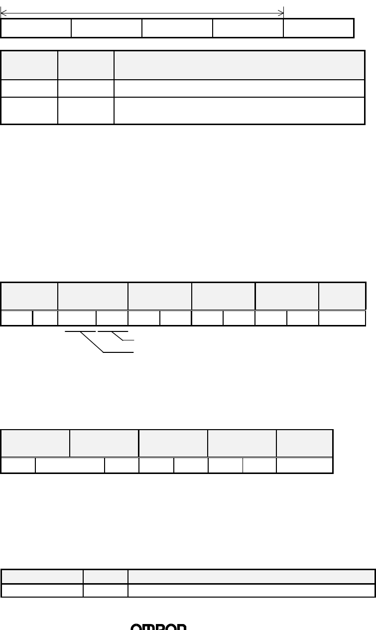
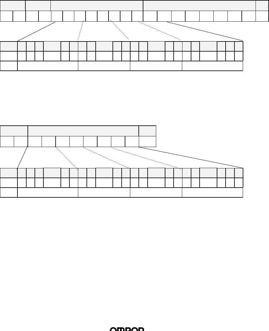
(1) Read
Read command is used when data is to be read from the Tag. Data for any
specified page may be read. The maximum number of pages that may be read
at one time is 16.
n
Command
The pages to be read as parameters will be transmitted. Page specifications shall
be made by specifying the bit indicating the page as “1” and the other bytes as “0”.
This binary is converted to a hexadecimal and transmitted as a command. Pages
can be specified at random.
Command Communication
Option Page specification (8 characters) Terminator
“0” “1”CR
Bit 7 6 5 1 0 7 6 1 0 7 6 1 0 7 6 2 1 0
Page 30 29 28 ~24 23 22 21 ~16 15 14 13 ~8 7 6 5 ~1* *
Value “00” ~ “FF” “00” ~ “FF” “00” ~ “FF” “00” ~ “FC”
*0,1 bits should be specified as “0”. When “1” is specified, it will be regarded as
an error (error code 14).
n
Response
The completion code (“00” when normal) and read data will be transmitted. The
read data will be transmitted continuously according to the order of page
specification. When an error occurs, the error code is transmitted as a completion
code for the reply.
Completion code Read data* Terminator
“0” “0”CR
*Data number n = specified page x 8 (2 characters each in HEX specifications,
one character each in ASCII codes.)
<Command Example>
When reading all 6 pages from pages 1, 3, 5 ~ 8 using the single trigger mode
with HEX specification:
0100000003D4 [CR]
(00000000000000000000001111010100b)
(Data n)
⋅ ⋅ ⋅
(Data 1)
(17/30)
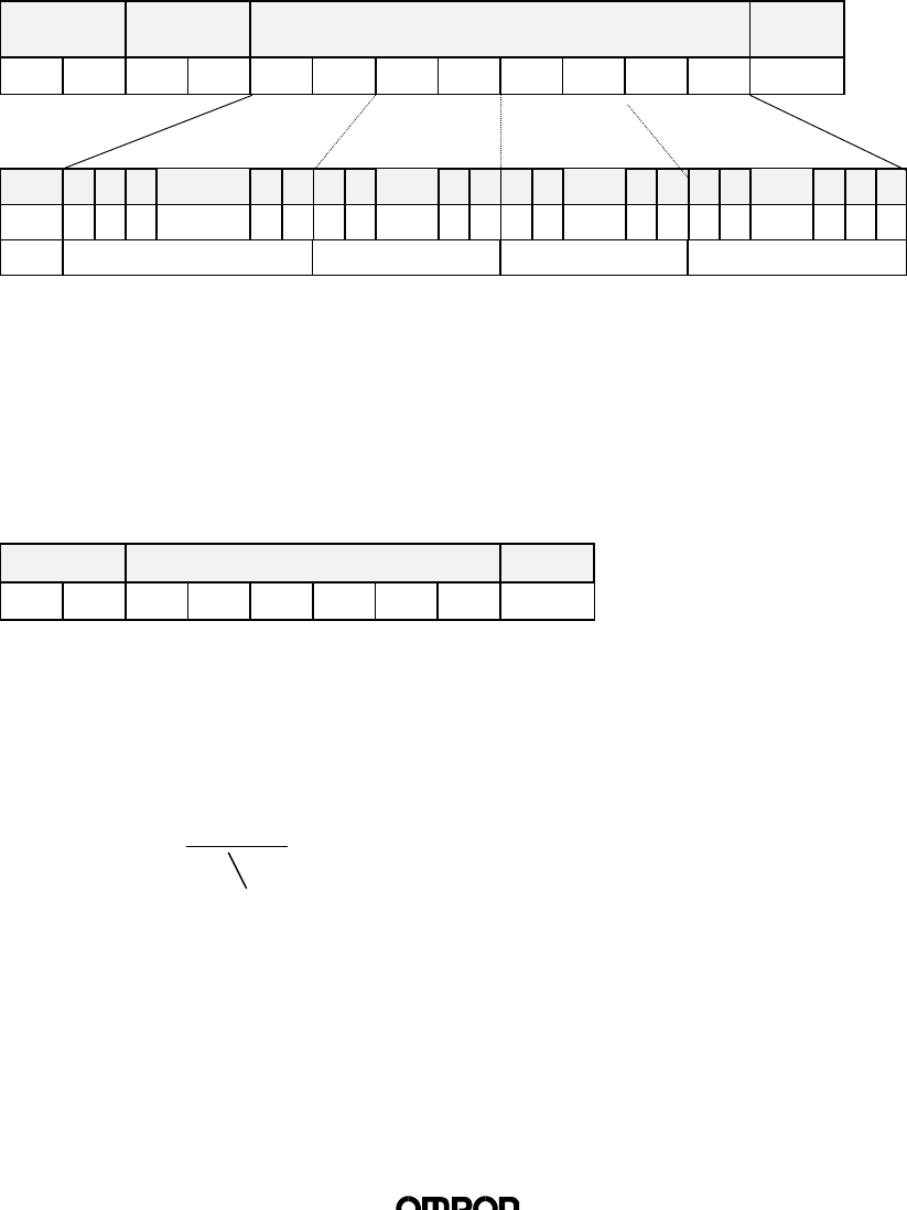
(2) Write
The Write command is used when data is to be written onto the Tag Memory
in units of pages. Data can be written on any specified page. The maximum
number of pages onto which data may be written at one time is 16.
n
Command
The pages to be written on, as parameters and the data to be written onto each
page will be transmitted. Page specifications shall be made by specifying the bit
indicating the page as “1” and the other bytes as “0”. This binary is converted to a
hexadecimal and transmitted as a command. Data to be written should be specified
in the order of specification of the designated pages.
Command Option Page specification (8 characters) Data to be written*
“0” “2”CR
Bit 7 6 5 1 0 7 6 1 0 7 6 1 0 7 6 2 1 0
Page 30 29 28 ~ ~ 24 23 22 21 ~16 15 14 13 ~8 7 6 5 ~1** **
Value “00” ~ “FF” “00” ~ “FF” “00” ~ “FF” “00” ~ “FC”
*Data number n = specified page x 8 (2 characters each in Hex data, one
character each in ASCII code)
** 0, 1 bits should be specified as “0”. When “1” is specified, it will be regarded
as an error (error code 14).
n
Response
The completion code (“00” when successful) will be transmitted.
Completion
code Terminator
“0” “0”CR
<Command Example>
When writing 2 pages of data onto pages 8 and 9 using the FIFO repeat mode
with ASCII specification:
021B00000600 (Data on page 8) (Data on page 9) [CR]
(000000000000000000000011000000000b)
(Data n)
⋅ ⋅ ⋅
(Data 1)
(18/30)
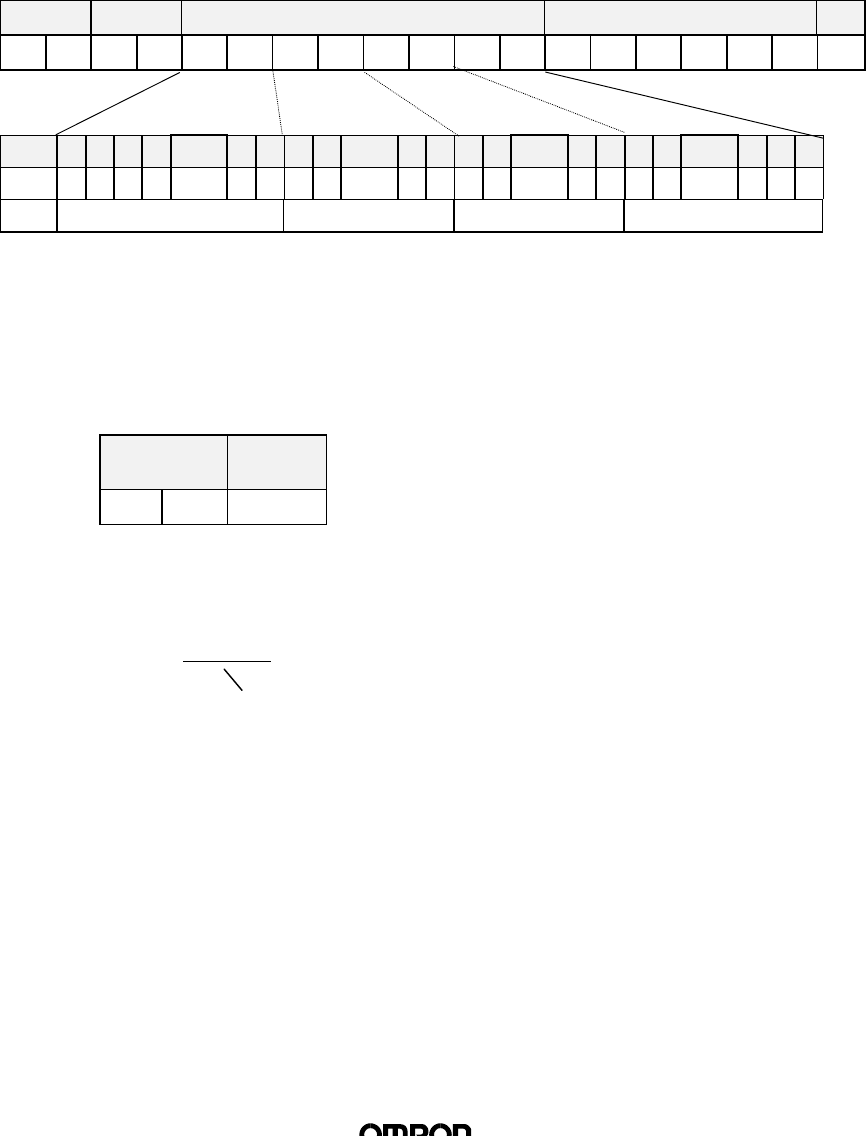
(3) Multiple Write
The Multiple Write command is used when the same data is written in units of
pages. Pages may be specified at random. There is no limit on the number of
pages that may be written at one time.
n
Command
The designated pages to be written as parameters and the data to be written onto
each page is transmitted. Page specifications shall be made by specifying the bit
indicating the page as “1” and the other bytes as “0”. This binary is converted to a
hexadecimal and transmitted as a command. Data to be written should be specified
in the order of specification of the designated pages.
Command Option Page specification Data to be written*
“0” “3”CR
Bit 7 6 5 1 0 7 6 1 0 7 6 1 0 7 6 2 1 0
Page 30 29 28 ~24 23 22 21 ~16 15 14 13 ~8 7 6 5 ~1** **
Value “00” ~ “FF” “00” ~ “FF” “00” ~ “FF” “00” ~ “FC”
*Data number n = 8 (2 characters each in Hex code, one character each in
ASCII code)
** 0, 1 bits should be specified as “0”. When “1” is specified, it will be regarded
as an error (error code 14).
n
Response
The completion code (“00” when successful) will be transmitted.
Completion
code Terminator
“0” “0”CR
(Data n)
⋅ ⋅ ⋅
(Data 1)

(19/30)
⋅ ⋅ ⋅
(4) Byte Write
The Byte Write command is used when data is to be written onto the Tag in
unit of Bytes. Data of any bytes can be written from the specified address. An
area spanning over more than one page may be specified, but a maximum
limit of 16 pages applies.
n
Command
The area’s leading address and the data to be written as parameters will be
transmitted. The address may be specified within the range of 00h ~ EFh. The data
to be written is to be specified in ascending order from the specified address.
Command Option Designated
Address Data to be written* Terminator
“0” “4”CR
*Data number n = number of bytes to be written (2 characters each for HEX
code, one character each for ASCII code.)
n
Response
The completion code (“00” when normal) will be transmitted.
Completion
code Terminator
“0” “0”CR
(Data n)
(Data 1)
(20/30)
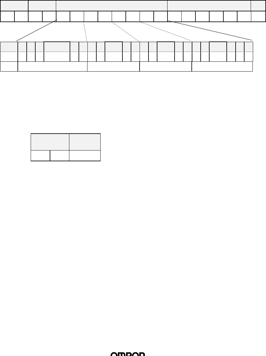
(5) Write Protection
The Write Protection command is used to set or turn off write protection on
Tag.
n
Command
The pages to set or turn off write protection on as parameters will be transmitted.
Page specifications shall be made by specifying the bit indicating the page as “1”
and the other bytes as “0”. This binary is converted to a hexadecimal and
transmitted as a command. If set and turn off were specified for the same page, the
set command will have priority.
The communication operation that may be specified as options, are 0 (single
trigger) and 8 (FIFO trigger).
Command Option Setting specification (8 characters) Turn off specification (8 characters)
“0” “8”CR
Bit 7 6 5 1 0 7 6 1 0 7 6 1 0 7 6 2 1 0
Page 30 29 28 ~24 23 22 21 ~16 15 14 13 ~8 7 6 5 ~1* *
Value “00” ~ “FF” “00” ~ “FF” “00” ~ “FF” “00” ~ “FC”
*0,1 bytes should be specified as “0”. When “1” is specified, it will be regarded
as an error (error code 14).
n
Response
The completion code (“00” when normal) and write protection status information will
be transmitted.
Command Setting specification (8 characters)
“0” “0”CR
Bit 7 6 5 1 0 7 6 1 0 7 6 1 0 7 6 2 1 0
Page 30 29 28 ~24 23 22 21 ~16 15 14 13 ~8 7 6 5 ~1* *
Value “00” ~ “FF” “00” ~ “FF” “00” ~ “FF” “00” ~ “FC”
*0, 1 bits are indicated as “0”.
(Data 1)
(Data 2)
(Data 3)
(Data 4)
(Data 1)
(Data 2)
(Data 3)
(Data 4)
(Data 1)
(Data 2)
(Data 3)
(Data 4)

(21/30)
(6) ACK
ACK is transmitted after receiving the response during FIFO Continue
operation, and it allows reading of the following:
n
Command
Command Terminator
“1” “1”CR
n
Response
There is no response.
(7) NACK
When the High-end device was not able to receive a response correctly, NACK
is transmitted to demand the response to be transmitted again. When the
Reader Writer receives this command, the most recent response will be
transmitted again.
n
Command
Command Terminator
“1” “2”CR
n
Response
The most recent response will be transmitted again.
(8) STOP
The STOP command is used to stop the Reader Writer executing a command.
When the Reader Writer receives this command, it immediately stops the
execution of the current command and sets on stand by mode for a new
command.
n
Command
Command Terminator
“1” “3”CR
n
Response
Completion
Code Terminator
“0” “0”CR

(22/30)
(9) Oscillation ON / OFF
The Oscillation ON / OFF command specifies the oscillation of the antenna.
n
Command
Oscillation ON Oscillation OFF
Command Terminator Command Terminator
“1” “4”CR “1” “5”CR
n Response
Completion Code Terminator
“0” “0”CR
(10) Test
The Test command is to conduct transmission tests on the communication to
the High-end device. When the Reader Writer receives this command, it
transmits the same command to the High-end device.
n
Command
Command Test Data Terminator
“1” “0”CR
n
Response
Completion
code Test Data (Same data as the command) Terminator
“0” “0”CR
(Data n)
⋅ ⋅ ⋅
(Data 1)
(Data n)
⋅ ⋅ ⋅
(Data 1)

(23/30)
5. Transmission Specification (Reference Values)
5.1 Transmission Distance
The transmission distance specifications are as follows. Please take note that
transmission distance is subject to change, depending on installation requirements.
Please refer to “6. The Influence of Requirements of Use on Transmission
Distance.”
Tag Transmission
Distance
Still 8 ∼ 43 mm
Model V700-D13P31
In motion 20 ∼ 43 mm
Still 8 ∼ 43 mm
Model V700-D13P21
In motion 20 ∼ 43 mm
Note 1. The read distance and write distance are the same
2. The values indicated above are based on the assumption that there is no axis
variation.
(24/30)
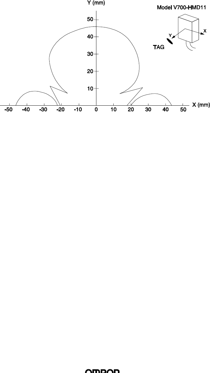
5.2 Transmission Area
• Reader Writer: Model V700-HMD11
• Tag: Model V700-D13P31 / Model V700-D13P21
The transmission area diagram going through the center of the antenna and
indicated on a flat surface vertical to the antenna surface is as indicated below.
Read / write are the same area.
(25/30)
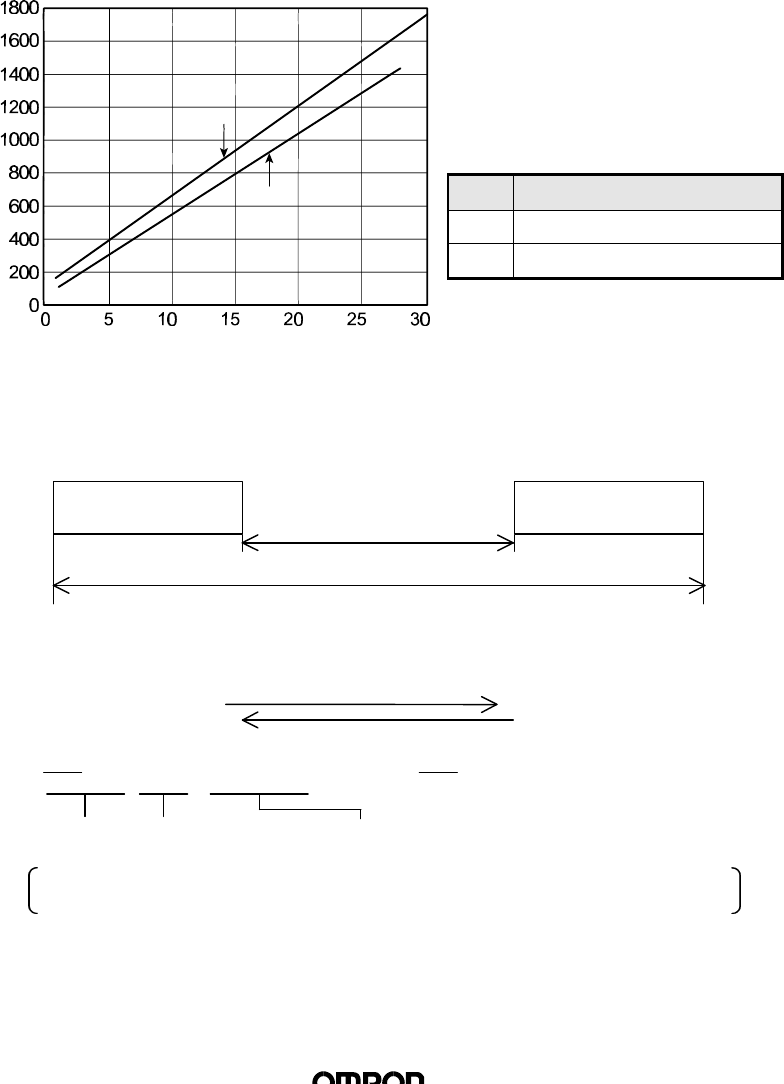
5.3 Communication Time
The Model V700 Series has two communication times: the transmission time and
the TAT (Turn Around Time).
(1) Transmission Time
This is the transmission processing time between the Reader Writer and the
Tags. This time varies in accordance with the number of pages to be read /
written.
The transmission time values are as indicated below. This value is estimated
based on the assumption that the transmission operation is on trigger mode
and that there is no interference in transmission due to noise and other causes.
(2) TAT
This is the time required for the high-end unit to transmit a command to the Reader
Writer, and to complete receipt of a response. This time varies in accordance with
the transmission speed and the communication control mode.
<Example of TAT Calculation>
• Read 1 page
(bit time) (number of bits per character) (number of characters transmitted)
Prerequisites: 1HEX code specification
2No spaces between characters; all data sent consecutively
Total pages processed
Transmission Time
(ms)
Write
Read
Command Response
TAT
Transmission time
Transmission Time Calculation Formula
Transmission Time (msec)
Read T=48N+66
Write T=55N+120
N: pages to be processed
Command
010000000004[CR]
Transmission time Response
001234567890ABCDEF[CR]
( ) ( ) ( ) ( ) ( ) ( ) ( ) ( )
sec1511911sec
9600
1
sec1141311sec
9600
1mcharactersbitsmcharactersbits =××++××
(26/30)
6. The Influence of Requirements of Use on Transmission
Distance (Reference Values)
When using the Reader Writer, transmission distance varies in accordance with the
requirements of use (the existence / non-existence of metal objects in the vicinity, the use
/non-use of multiple Reader Writer, power voltage value, etc.). This section indicates how
such requirements and changes in them affect communication distance. Please use the
following figures for your reference. Note that all values indicated in this section are reference.
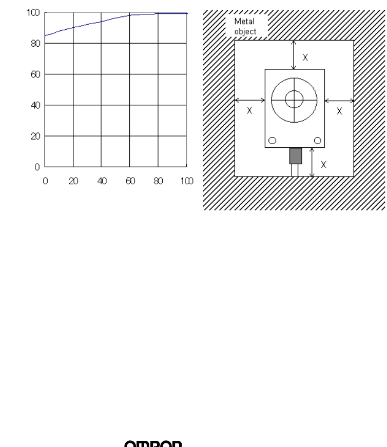
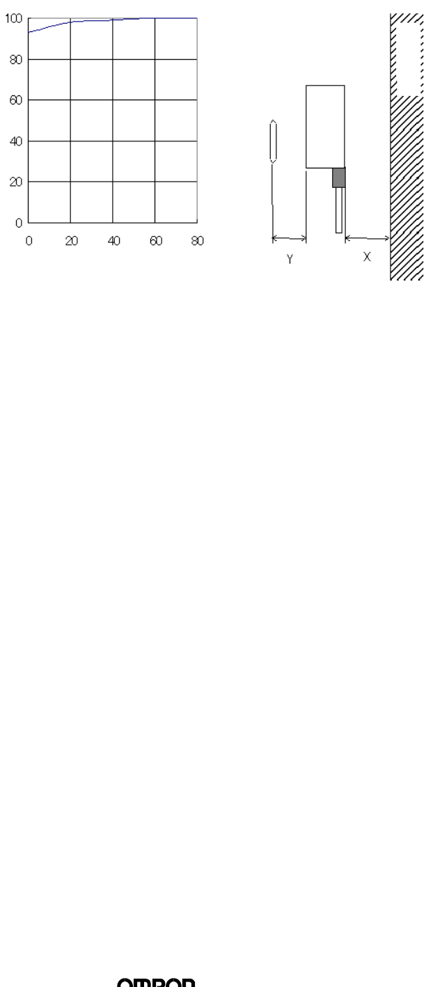
6.1 Influence of Metal Objects Surroundings and Metal Objects Behind the
Device
When metal objects are around or behind the Reader Writer, transmission distance
deteriorates. Please take note of the distance between the metal objects and the
Reader Writer as per below when using the Reader Writer.
When the metal object is steel, the relationship between the distance of the metal
objects around and behind the Model V700-HMC71 from the device and the
transmission distance (read / write) is indicated below. The following values were
obtained by using Tags Model V700-D13P31 / Model V700-D13P21 with an axis
variation of +- 0 mm.
n Surrounding Metal Objects
Transmission distance
(no surrounding metal=%100) Y (%)
Distance away from metal X (mm)
(27/30)
n Metal Objects behind Reader Writer
Distance away from metal X (mm)
Transmission distance
(no metal behind Reader Writer=%100) Y (%)
Metal Object
Model V700-HMD11
TAG
(28/30)
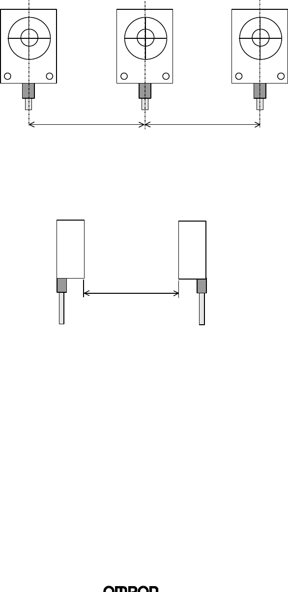
6.2 Mutual Interference between Reader Writers
When using more than one Reader Writer, to prevent erroneous operations due to
interference from other Reader Writers, please be sure to check that the below-
indicated distance between Reader Writers is secured.
n When Using Multiple Reader Writers in a Line
410mm or more
n When Using the Reader Writers Facing Each Other
460mm or more
410mm or more 410mm or more
460mm or more

(30/30)
Appendix 1 Document Revision History
Date Modification Contents
Oct., 1998
July 2000
First Edition
“Applicable Standards” is added on the page 2