Omron 6CYAIDV7000100 RF-ID System User Manual V700HMC 7173 Manual 2000 7
Omron Corporation RF-ID System V700HMC 7173 Manual 2000 7
Omron >
Contents
- 1. Manual HMC71 and 73
- 2. Manual HMD11
Manual HMC71 and 73

(1/23)
Operation Manual
Issued: July 7, 2000
Product Name:
R/W Module Board Type (L) V700-HMC71
R/W Module Board Type (S) V700-HMC73
OMRON Corporation
Industrial Automation Company
Advanced Sensors Development Department
Sensing Devices & Components Division H.Q.
Revision history Revised date Revised item
−′98/ 7/ 17 New issue
′00/ 7/ 07 “Applicable Standards” is added on the page 2

(2/23)
Applicable Standards
FCC (USA) Part 15 subpart B and C
This device complies with part 15 of the FCC Rules. Operation is subjected to the following
two conditions:
(1) This device may not cause harmful interference, and (2) this device must accept any
interference received, including interference that may cause undesired operation.
FCC ID : E4E6CYAID7000100
FCC NOTICE
This equipment has been tested and found to comply with the limits for a Class B digital device,
pursuant to part 15 of the FCC Rules. These limits are designed to provide reasonable
protection against harmful interference in a residential installation.
This equipment generates, uses and can radiate radio frequency energy and, if not installed and
used in accordance with the instructions, may cause harmful interference to radio
communications. However, there is no guarantee that interference will not occur in a particular
installation. If this equipment dose cause harmful interference to radio or television reception,
which can be determined by turning the equipment off and on, the user is encouraged to try to
correct the interference by one or more of the following measures:
-Reorient or relocate the receiving antenna.
-Increase the separation between the equipment and receiver.
-Connect the equipment into an outlet on a circuit different from that to which the receiver is
connected.
-Consult the dealer or an experienced radio / TV technician for help.
FCC WARNING
Changes or modifications not expressly approved by the party responsible for compliance could
void the user’s authority to operate the equipment.
Properly shielded an grounded cables and connectors must be used for connection to host
computer and / or peripherals in order to meet FCC emission limits.
AC adapter with ferrite core must be used for RF interference suppression.
Precautions of Use
This device uses a frequency of 125 kHz to communicate with a tag. Some transceivers,
motors, monitor units, and power supply (power IC) emit noise that adversely affects this
communication with the tag. If this product is to be used in an environment close to such
devices, please check the effects from these devices prior to use.
To minimise the effect of noise, please ground any metal object surrounding this device.

(3/23)
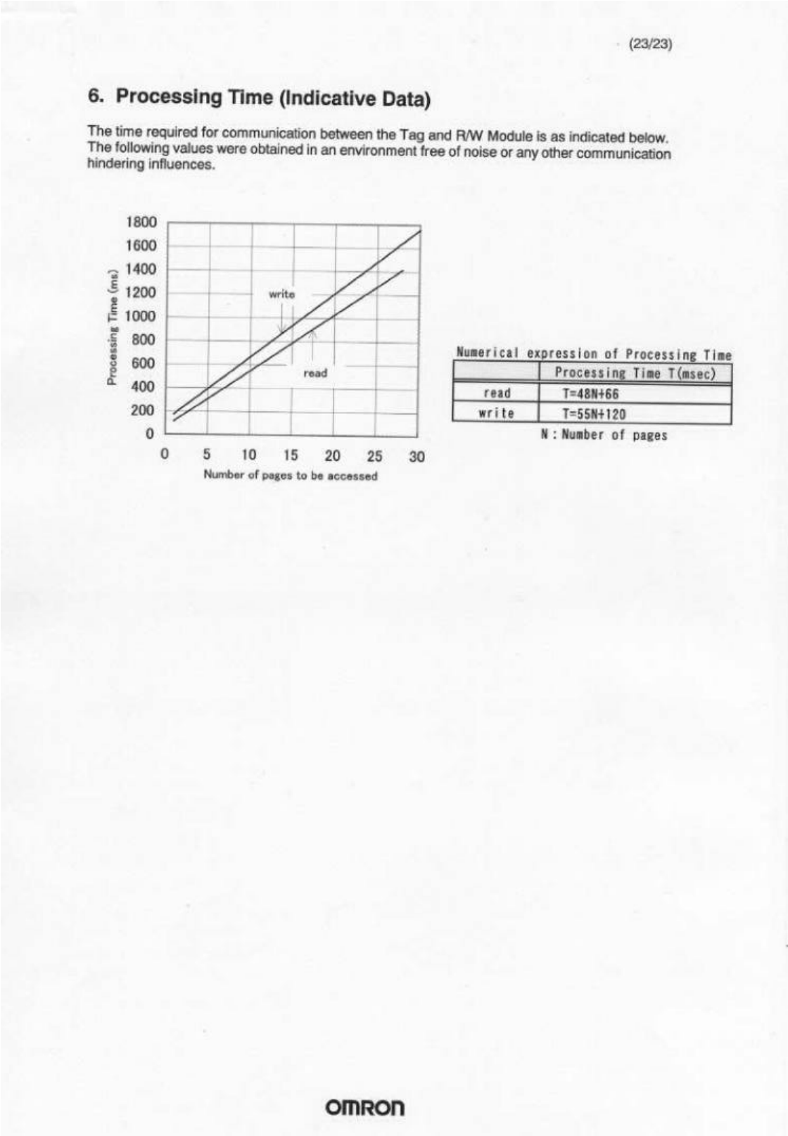
This manual specifies the specifications and transmission format of the R/W Module.
Table of Contents
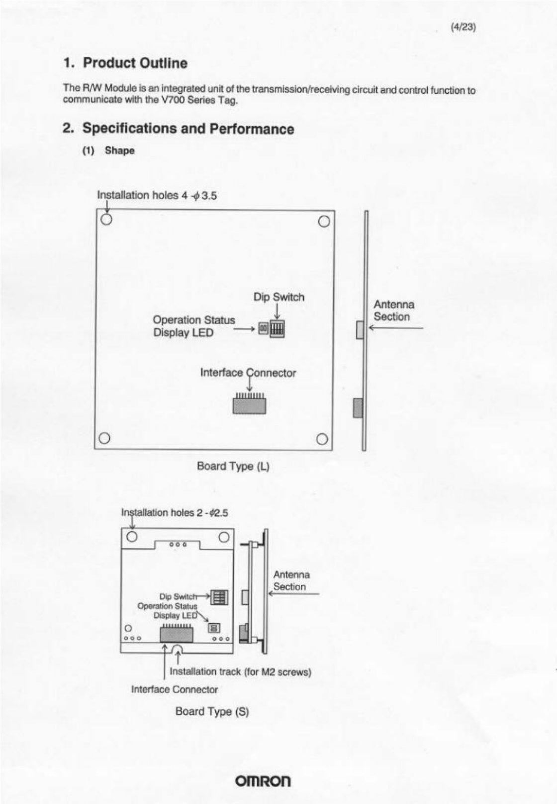
1. Product Outline ................................................................................... 4
2. Specifications and Performance.......................................................... 4
3. Operations of the R/W Module ............................................................ 9
3.1 Outline of operations.................................................................... 9
3.2 Oscillation Control........................................................................ 9
3.3 Input STOP................................................................................ 10
3.4 Memory Management on Tag.................................................... 10
3.5 Processing Tag Memory............................................................ 11
4. Controlling the Module from User board............................................ 14
4.1 Transmission Control Format .................................................... 14
4.2 Command/Response Format .................................................... 15
4.3 Types of Commands and Responses ....................................... 16
5. Error Code List................................................................................... 22
6. Processing Time (Indicative Data)..................................................... 23

(5/23)
• Dip Switch
Will not be used. Turn every dip switch OFF.
• Operating conditon displaying LED
LED Display Detail
Green lights on Lights on when communicating with the Tag
Red lights on Lights on when communication process does not complete
successfully.
• Interface Connector
This connector connects the R/W module to a User Board.
• Antenna Section
When communicating with the Tag, please bring the Tag close to the antenna
section.
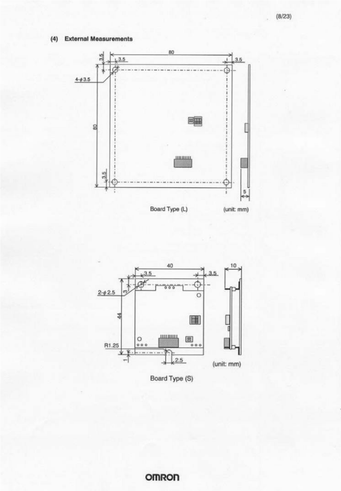
(2) General Specifications
Item Board Type (L) Board Type (S)
External measurement 80 × 80 × 5 mm 40 × 44 × 10 mm
Installation 4 points Secured by
M3 screws Secured at 3 points,
M2 or M2.3 screws
Electric current 5V ±10%
Dissipation current 180 mA or less (during oscillation)
20 mA or less (no oscillation)
Vibration resistance Destruction: 20m/s2 10 to 150Hz, 0.15mm double
amplitude, with 4 sweeps of 8min each in 3 directions
Shock resistance Destruction: 200m/s2, 3 times each in 6 directions
Ambient temperature
during use -10 ~ +55°C
Ambient temperature
during storage -25 ~ +65°C
Ambient humidity
during use 25 ~ 85% RH or less (with no condensation)
Radio frequency 125 kHz
Transmission distance
(Tag: V700 - D13P31)
Distance at center of
coil - Tag axis
5 ~ 65 mm 10 ~ 40 mm
(6/23)
(3) Signal Interface Specifications
Item Specifications
Connector
specifications S10B-ZR-SM3A-TF
(manufactured by J.S.T. MFG CO.,LTD.)
(applicable wires: AWG#32 ~ #26)
Transmission format 2 wire system semi-double serial (CMOS level)
Synchronization format Asynchronous mode; start-stop system
Transmission control
format Cr control
Transmission speed 9600 bps (fixed)
Character format (fixed) Start bit Data bit Parity bit Stop bit Total
1 8 Even 1 11
Error detection format Even number parity
Bit transmission order Low order fist (from LSB)
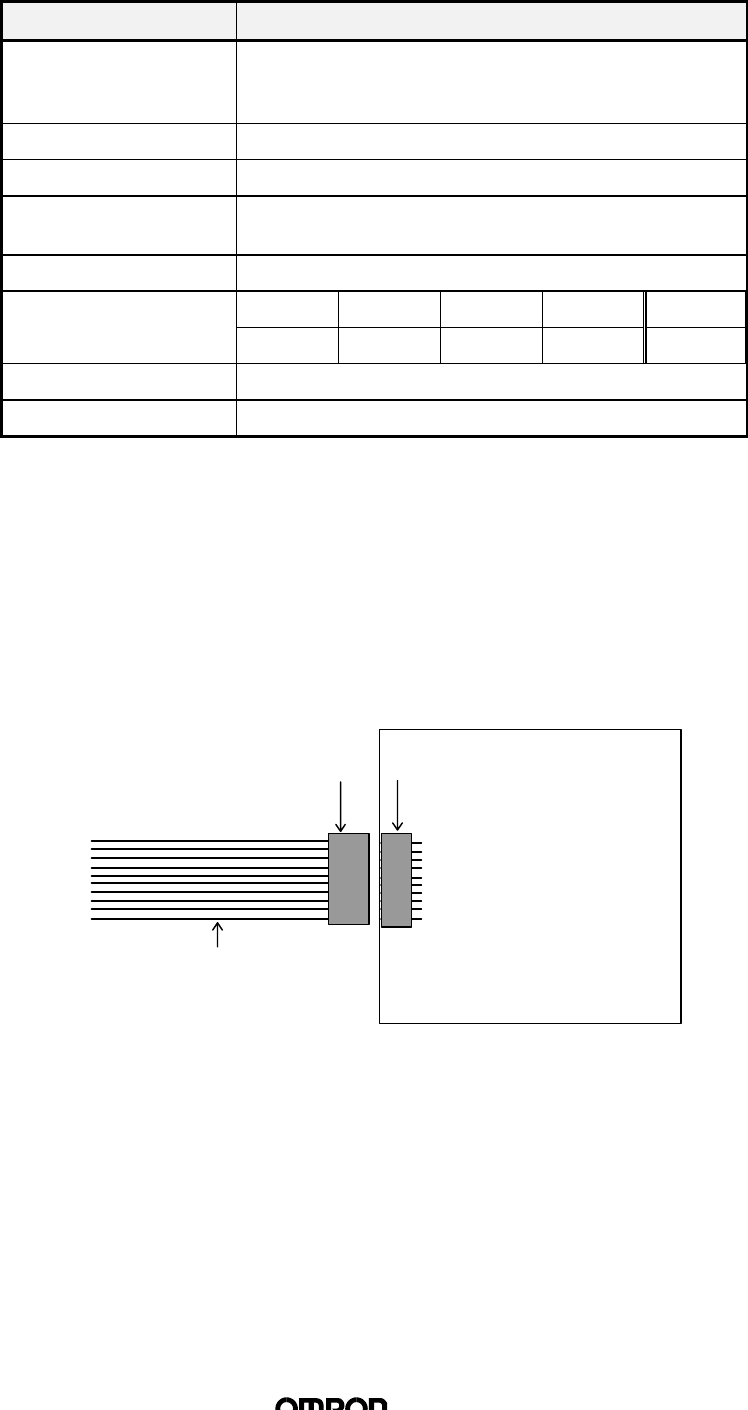
n Pin Layout and Connection with User board
For housing of cable connecting the R/W Module with the User board, please use the
following:
Manufactured by J.S.T. MFG CO.,LTD.
Socket housing: ZHR-10
Socket contact: SZH-002T-P0.5 or SZH-003T-P0.5
Housing: ZHR-10
Applicable wires:
AWG#32 ~ #26
1
2
:
:
:
:
10
Pin Header: S10B-ZR-SM3A-TF
R/W Module
(7/23)
n
Names of Signals and Functions
No. Codes I/O Function Performance Signal Logic
15V -Power 5V ±10% -
2GND -Ground - -
3RXD Input Serial input CMOS CMOS input
47 kΩ pull up 0:0V, 1:5V
(positive logic)
4TXD Output Serial output CMOS output
IOL=2mA,
IOH=2mA
5STOP Input Receive process of command
being executed / command
execution will be aborted and
after STOP is input, will be on
stand by for command
CMOS input
47 kΩ pull up ↓ active
6EXT_IN Input (unused) CMOS input
47 kΩ pull up -
7COMM Output Will be output while
communication is occurring
between tag
CMOS output
IOL =10mA,
IOH =2mA
H active
8NORM Output Will be output after
transmission with tag is
successfully completed
CMOS output
IOL =10mA,
IOH =2mA
H active
9ERR Output Will be output when
transmission with tag was
unsuccessful
CMOS output
IOL =10mA,
IOH =2mA
H active
10 RUN Output Will be output when Module is
operating normally CMOS output
IOL =10mA,
IOH =2mA
H active
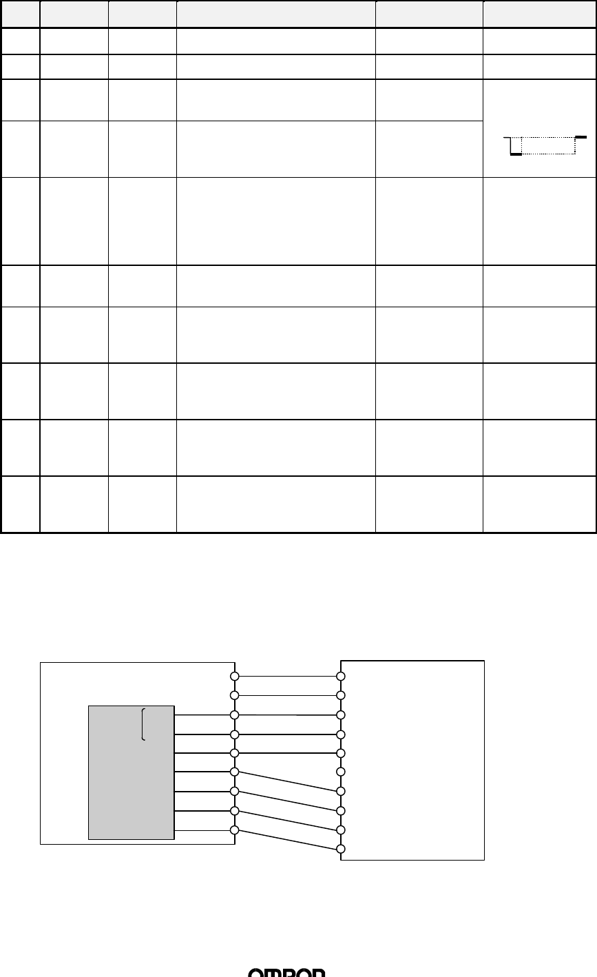
n
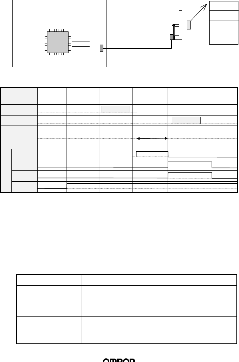
Example of Connection with User board
Please refer to the below-indicated connection for connecting the Module to the User board. Any
signals that will be unused should not be connected.
5V
GND
5V(1)
GND(2)
RXD(3)
TXD(4)
STOP(5)
EXT_IN(6)
COMM(7)
NORM(8)
ERR(9)
RUN(10)
TXD
RXD
OUT1
IN1
IN2
IN3
IN4
User board
User CPU
R/W Module
Numbers in ( ) indicates
pin number
SCI
0V data
SE
5V
(9/23)
3. Operations of the R/W Module
3.1 Outline of operations
The R/W Module receives commands from the User board, executes read / write
processes on the Tag, and returns a response of the results of the process to the
User board. The status of the R/W Module operations will be reflected on the Output
/ LED.
n
Operations Timing Chart
Status Initial
process Waiting for
command Receiving
command Processing
command Transmitting
response Waiting
command
TXD Command
RXD Response
Tag
communi-
cations
COMM ↓
NORM ↓
ERR ↓
RUN ↓
3.2 Oscillation Control
The R/W Module supplies power to the Tag by oscillating the antenna, and thus
conducts communication with the Tag. The Module may be set on either the
“Oscillate Mode” “Stop Mode” depending on whether the Module should oscillate
while not in communication with the Tag. The “Stop Mode” conserves dissipation
power, and enables the R/W Module antenna to be installed close to the Tag to
conduct communications on a time sharing basis. The “Oscillate Mode” allows the
Module to constantly supply power to the Tag for FIFO processing.
Oscillation Status Operation Mode Switching Conditions
Stop Mode (conserves
dissipation power) The antenna stops
oscillating while not
processing commands
• Mode switching conditions at
start-up
• When oscillation OFF
command is active
Oscillation Mode
(enables high-speed
processing)
The antenna is
constantly oscillating • When oscillation ON command
is active
• When option is active in FIFO
Trigger / FIFO Auto Command
Out-
put /
LED
Page 1
Page 2
:
Page n
User CPU
R/W Module
Tag
User Board

(10/23)
3.3 Input STOP
When a STOP signal is input to the R/W Module, receiving and processing of
commands and command processing will stop and then, after the STOP signal is
deactivated, the Module will be on stand by for new commands. When the STOP
signal is input, oscillation will stop regardless of the setting of the oscillation control
mode.
If a STOP signal is input more than 50 msec prior to shut down, writing of unstable
data to the Tag may be prevented. However, if writing of the command in process
requires more than one page, not all pages may be completely rewritten.
3.4 Memory Management on Tag
The Tags used to conduct communication with the R/W Module may be one of the
following two types depending on memory capacity: 128 bytes (user area 112 bytes)
or 256 bytes (user area 240 bytes). The memory area recognizes every 8 bytes as
one page, distinguished by such addresses as 00h ~ 07h, 08h ~ 0Fh, and so on.
n
Memory Map (00h ~ EFh indicates to address)
Page 8 bytes / page
1 00h 01h 02h 03h 04h 05h 06h 07h
2 08h 09h 0Ah 0Bh 0Ch 0Dh 0Eh 0Fh
3 10h 11h 12h ⋅⋅⋅ ⋅⋅⋅ 17h
4 18h 19h 1Ah ⋅⋅⋅ ⋅⋅⋅ 1Fh
5 20h 27h
6 28h 2Fh
7 30h 37h
8
9
10 : :
11 : :
12
13
14 68h ⋅⋅⋅ ⋅⋅⋅ 6Fh
15 70h ⋅⋅⋅ ⋅⋅⋅ 77h
16 78h ⋅⋅⋅ ⋅⋅⋅ 7Fh
: : :
: : :
29 E0h E1h ⋅⋅⋅ ⋅⋅⋅ E7h
30 E8h E9h ⋅⋅⋅ ⋅⋅⋅ EFh
112 bytes
240 bytes
(11/23)
3.5 Processing Tag Memory
(1) Process Contents
The following three processes may be executed on the Tag Memory
1) Read
Reading data from Tag Memory. The area to execute the Read command
may be selected at random up to 16 pages.
2) Write
Writing data onto Tag Memory. The area to execute the Write command
may be selected at random up to 16 pages. When writing the same data
onto all pages (multiple write), there is no limitation on the number of pages.
Certain data within a page may be selected in units of bytes to be written
onto the Tag Memory (byte write).
3) Write Protection Set/OFF
Write protection may be set on the selected pages of Tag Memory. When
write protection is set, the data may be read, but not re-written. Write
protection may be set on any of the pages. Write protection may be set or
turned off by commands.
(2) Communication Operations
The following 6 communications operation may be executed by changing the
process procedure and execution timing. Communication operations may be
specified by commands during command transmission.
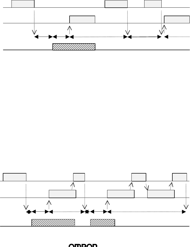
1) Single Trigger
Communication with Tag will be executed immediately after receiving
command and a response will be transmitted. After response is transmitted,
the Module will be on stand by for new commands. During communication
with the Tag, there may only be one Tag within the communication area.
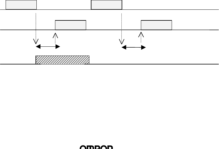
♦ Operation Sequence
Processing will be executed once only after receiving command. If there is
no Tag, a Tag absent error message will be transmitted.
Tag
Communication
Tag 1
Tag Operation
User ←
User →Command Command
Response 2
(Tag Absence Error)
Command Process
Command Process
Response 1
(12/23)
2) Single Auto
After receiving command, the Module waits for the Tag to approach,
communicates with the Tag, and then transmits a response. Once the
response is transmitted, Module will be on stand by for new commands.
During communication with the Tag, there must be one Tag within the
communication area.
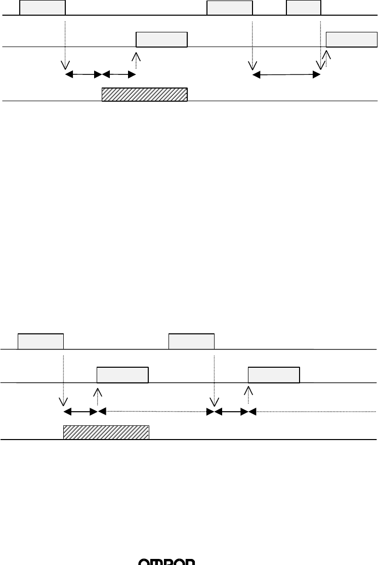
♦ Operation Sequence
After receiving command, the Module waits for the Tag to approach, then
executes process once only after Tag is detected. When Module receives a
STOP command, the command will be completed.
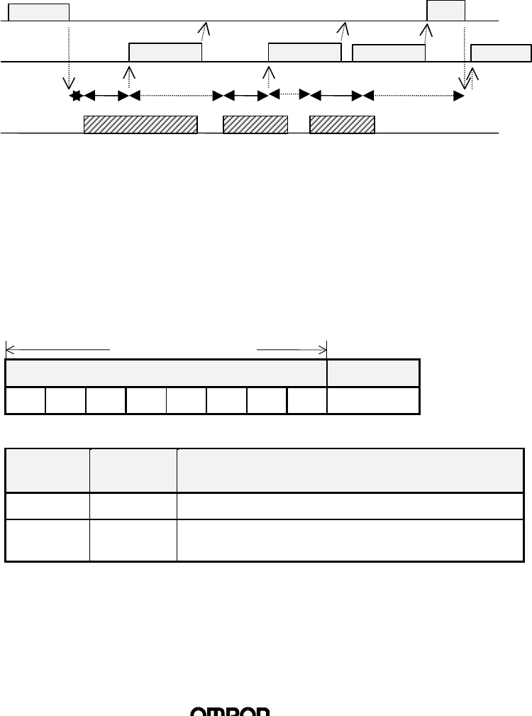
3) FIFO Trigger
Module will communicate with Tag immediately after receiving command
and transmit response. After communication is completed, Module will
prohibit Tag from operating. Module will be on stand by for commands after
response is transmitted. During communication with Tag, there MUST BE
AN OPERATIONAL TAG (A TAG THAT IS NOT PROHIBITED FROM
OPERATION) within the communication area. When this command is
executed, Module automatically activates “Oscillation Mode”
♦ Operation Sequence
Upon receiving command, Module will execute process once only. If there
is no Tag, a Tag absence error will be transmitted. During processing of the
command, Tag will become inoperative, and thus will not respond to the
next command. Oscillation will continue after command is processed.
Tag 1
Tag
Communication
Tag Operation
User ←
User →
Command Command
(Tag Absence Error)
Command Process
Command Process
(Oscillation)
(Oscillation)
Response 2Response 1
Response
Tag
Communication
Tag 1
Tag Operation
User ←
User →
Command
Command
STOP
(Truncation
Process)
Tag Detection
Tag
Detection
Command Process
Response
(13/23)
4) FIFO Auto
Module will await Tag to approach after receiving command, then
communicate with Tag and transmit response. After communication is
completed, Module will prohibit Tag from operating. Module will be on stand
by after response transmission is completed. During communication with
the Tag, there MUST BE AN OPERATIONAL TAG (A TAG THAT IS NOT
PROHIBITED FROM OPERATION) within the communication area. When
this command is executed, Module automatically activates “Oscillation
Mode.”
♦ Operation Sequence
After receiving command, the Module waits for the Tag to approach, then
executes process once only after Tag is detected. During processing of the
command, Tag will become inoperative, and thus will not respond to the
next command. Oscillation will continue after command is processed.
When Module receives a STOP command, the command will be
completed.
5) FIFO Continue
After receiving command, the Module waits for the Tag to approach, then
communicates with the Tag and transmits a response. After communication
is completed, Tag will become inoperative. After transmitting a response,
Module will await Tag to approach again if it receives [ACK], and
CONTINUE UNTIL MODULE RECEIVES A STOP COMMAND. When
communicating with the Tag, THERE MUST ONLY BE ONE ACTIVE TAG
within the communication area.
♦ Operation Sequence
Upon receiving the command, Module awaits Tag to approach. When Tag
is detected, Module executes command and transmits a response.
Afterwards, when [ACK] is received, Module repeats the same operation.
Once process is executed on a Tag, the Tag becomes inoperative, and thus
a Tag will only be processed once. When Module receives a STOP
command, processing will stop.
(Oscillation)
Tag 1
Command Command
Response
STOP
Response 1
1
Tag
Communication
Tag Operation
User ←
User →
Tag Detection
Tag
Detection
Command Process
(Truncation
Process)
(Oscillation)
Tag 2
Tag 1
Command STOPNACKACK
Response 2
Response 2
Response 1
Tag
Detection
Tag
Detection
Tag
Communication
Tag Operation
User ←
User →
Command Process
Command Process
(Oscillation)
(14/23)
6) FIFO Repeat
After receiving command, the Module waits for the Tag to approach, then
communicates with the Tag and transmits a response. After communication
is completed, Tag will become inoperative. MODULE WILL CONTINUE
PROCESS UNTIL IT RECEIVES A STOP COMMAND. When
communicating with the Tag, THERE MUST ONLY BE ONE ACTIVE TAG
(A TAG THAT IS NOT PROHIBITED FROM OPERATION) within the
communication area.
♦ Operation Sequence
Upon receiving the command, Module awaits Tag to approach. When Tag
is detected, Module executes command and transmits a response.
Afterwards, Module repeats the same operation. Once process is executed
on a Tag, the Tag becomes inoperative, and thus a Tag will only be
processed once. When Module receives a STOP command, processing will
stop.
4. Controlling the Module from User board
4.1 Transmission Control Format
The frame format consists of 16 types of text in even number units from through “0”~
“F” (Band the terminator [Cr] (ASCII code : 0Dh).
Text Terminator
Cr
Data Number of
characters Details
Text 1 ~ 272 Parameters of each command (“0” ~ “F”)
Terminator 1Code (0Dh) indicating the completion of transmission
frame
(Transmission Control Procedure)
Receipt commences when a character is received first, and when [Cr] is received,
the frame is recognized as finished. If the interval between data exceeds 2 seconds,
a transmission error will be recognized.
272 characters or less
Tag
Detection
Tag
Detection
Tag
Detection
Tag
Detection
STOP
Command
Response 3
Respons
Response 2
(Truncation
Process)
Command Process
Command
Command
Response 1
Tag 3
Tag 2
Tag 1
Tag
Communication
Tag Operation
User ←
User →

(15/23)
4.2 Command/Response Format
n
Command
The frame consists of an operation option, parameters, and terminator.
Communication options can be attached to commands No. 01 through 08 only.
Command Option Parameter 1 ~Parameter n Terminator
Cr
n
Response
The frame consists of a completion code, parameters, and terminator.
Completion
code Parameter 1 ~Parameter n Terminator
Cr
(1) Types of Commands
Specifies the process of the R/W Module
Command
Name Number Details
Read 01 Reads Tag Memory data in units of pages
Write 02 Writes data onto Tag Memory in units of pages
Multiple Write 03 Writes the same data onto Tag Memory in units of
pages
Byte Write 04 Writes data onto Tag Memory in units of bytes
Write
Protection 08 Specifies setting or to undo write protection per
page
ACK 11 Is sent when User board successfully receives data
NACK 12 Is sent when User board does not receive data
successfully
STOP 13 Stops processing of command being executed
Oscillation ON 14 Activates Oscillation Mode on Module Antenna
Oscillation OFF 15 Stops Oscillation Mode on Module Antenna
Test 10 Transmits data received directly back to User board
(16/23)
(2) Options
Specifies communication operations when command is one of 01 through 08.
Option Number Details
Single
Trigger 00 Conducts communication with Tag on Single Trigger
Mode
Single
Auto 01 Conducts communication with Tag on Single Auto Mode
FIFO
Trigger 08 Conducts communication with Tag on FIFO Trigger
Mode
FIFO Auto 09 Conducts communication with Tag on FIFO Auto Mode
FIFO
Continue 0A Conducts communication with Tag on FIFO Continue
Mode
FIFO
Repeat 0B Conducts communication with Tag on FIFO Repeat
Mode
(3) Completion Code
When command process is completed successfully, completion code becomes
“00”.
If process was not completed successfully, an error code will be transmitted.
4.3 Types of Commands and Responses
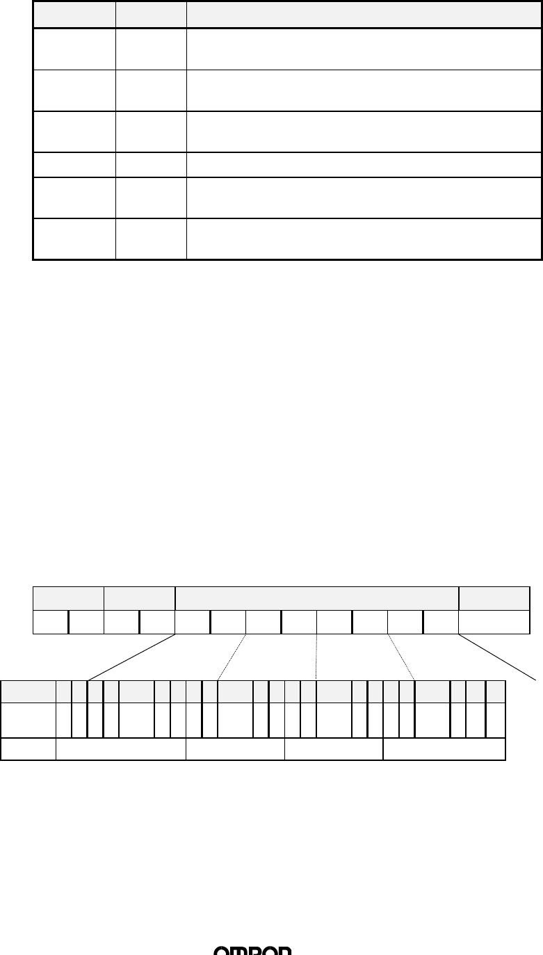
(1) Read
Read is used when data is to be read from the Tag. Data for any specified page
may be read. The maximum number of pages that may be read at one time is
16.
n
Command
The pages to be read will be transmitted as parameters. Page specifications shall be
made by specifying the bit indicating the page as 1 and the other bits as 0. Pages can
be specified at random.
Command Option Page specification (8 characters) Terminator
“0” “1”Cr
Bit 7 6 5 4 1 0 7 6 1 0 7 6 1 0 7 6 2 1 0
Page 3
0
2
9
2
8
2
7
~2
4
2
3
2
2
2
1
~1
6
1
5
1
4
1
3
~8 7 6 5 ~1* *
Value “00” ~ “FF” “00” ~ “FF” “00” ~ “FF” “00” ~ “FC”
*0,1 bits should be specified as 0. When 1 is specified, it will register as
an error (error code 14).

(17/23)
n
Response
The completion code (“00”when successful) and read data will be transmitted. The
read data will be transmitted continuously according to the order of page
specification.
Completion
code Read data* Terminator
“0” “0”Cr
*Data number n = specified page × 8
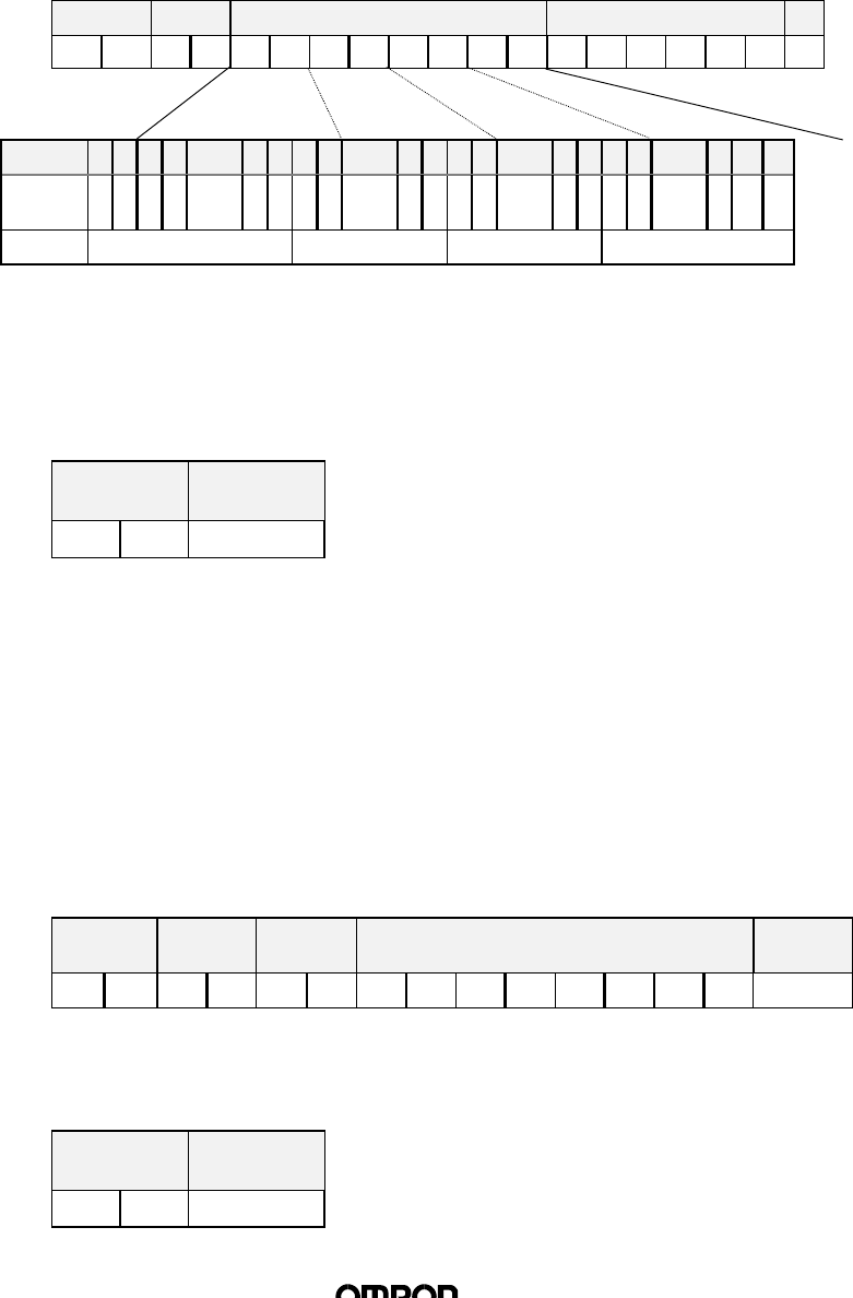
(2) Write
The Write command is used when data is to be written onto the Tag Memory in
units of pages. Data can be written on any specified page. The maximum
number of pages onto which data may be written at one time is 16.
n
Command
The pages to be written on and the data to be written onto each page will be
transmitted as parameters. Page specifications shall be made by specifying the bit
indicating the page as 1 and the other bits as 0. Data to be written should be specified
in the order of specification of the designated pages.
Command Option Page specification (8 characters) Data to be written*
“0” “2”Cr
Bit 7 6 5 4 1 0 7 6 1 0 7 6 1 0 7 6 2 1 0
Page 3
0
2
9
2
8
2
7
~2
4
2
3
2
2
2
1
~1
6
1
5
1
4
1
3
~8 7 6 5 ~1** **
Value “00” ~ “FF” “00” ~ “FF” “00” ~ “FF” “00” ~ “FC”
*Data number n = specified page x 8
** 0,1 bits should be specified as 0. When 1 is specified, it will register as an error
(error code 14).
n
Response
The completion code (“00” when successful) will be transmitted.
Completion
code Terminator
“0” “0”Cr
(Data n)
⋅ ⋅ ⋅
(Data 1)
(Data n)
⋅ ⋅ ⋅
(Data 1)
(18/23)
⋅ ⋅ ⋅
(3) Multiple Write
The Multiple Write command is used when the same data is written in units of
pages. Pages may be specified at random. There is no limit on the number of
pages that may be written at one time.
n
Command
The designated pages to be written and the data to be written onto each page is
transmitted as parameters. Page specifications shall be made by specifying the bit
indicating the page as 1 and the other bits as 0. Data to be written should be specified
in the order of specification of the designated pages.
Command Option Page specification Data to be written*
“0” “3”Cr
Bit 7 6 5 4 1 0 7 6 1 0 7 6 1 0 7 6 2 1 0
Page 3
0
2
9
2
8
2
7
~2
4
2
3
2
2
2
1
~1
6
1
5
1
4
1
3
~8 7 6 5 ~1** **
Value “00” ~ “FF” “00” ~ “FF” “00” ~ “FF” “00” ~ “FC”
*Data number n = 8
** 0,1 bits should be specified as 0. When 1 is specified, it will register as an error
(error code 14).
n
Response
The completion code (“00” when successful) will be transmitted.
Completion
code Terminator
“0” “0”Cr
(4) Byte Write
The Byte Write command is used when data is to be written onto the Tag
Memory in Units of Bytes. Data can only be written on the same specified page.
Data cannot be written on more than one page.
n
Command
The pages to be written on and the data to be written onto each page will be
transmitted as parameters. Address specifications are done by specifying the first
address where the data is to be written (specification range: 00h ~ EFh). Data will be
written in accordingly from the specified address. (The maximum volume of data is 8
bytes)
Command Option Designated
Address Data to be written* Terminator
“0” “4”Cr
*Data number n = number of bytes to be written (maximum 8)
n
Response
The completion code (“00” when successful) will be transmitted.
Completion
code Terminator
“0” “0”Cr
(Data n)
(Data n)
⋅ ⋅ ⋅
(Data 1)
(Data 1)

(19/23)
(5) Write Protection
The Write Protection command is used to set or turn off write protection on Tag.
n
Command
The pages to set or turn off write protection on will be transmitted as parameters.
Page specifications shall be made by specifying the bit indicating the page as 1 and
the other bits as 0. If set and turn off were specified for the same page, the set
command will have priority.
Command Option Setting specification (8 characters) Turn off specification (8 characters)
“0” “8”Cr
Bit 7 6 5 4 1 0 7 6 1 0 7 6 1 0 7 6 2 1 0
Page 3
0
2
9
2
8
2
7
~2
4
2
3
2
2
2
1
~1
6
1
5
1
4
1
3
~8 7 6 5 ~1* *
Value “00” ~ “FF” “00” ~ “FF” “00” ~ “FF” “00” ~ “FC”
*0,1 bits should be specified as 0. When 1 is specified, it will register as an error
(error code 14).
Command
code Setting specification (8 characters)
“0” “0”Cr
Bit 7 6 5 4 1 0 7 6 1 0 7 6 1 0 7 6 2 1 0
Page 3
0
2
9
2
8
2
7
~2
4
2
3
2
2
2
1
~1
6
1
5
1
4
1
3
~8 7 6 5 ~1* *
Value “00” ~ “FF” “00” ~ “FF” “00” ~ “FF” “00” ~ “FC”
*0, 1 bits are indicated as 0.
n
Response
The completion code (“00” when successful) and write protection status information
will be transmitted.
(6) ACK
ACK is transmitted after FIFO Continue is operated and the response is
received to allow reading of the following:
n
Command
Command Terminator
“1” “1”Cr
n
Response
There is no response.
(Data 4)
(Data 3)
(Data 2)
(Data 1)
(Data 4)
(Data 3)
(Data 2)
(Data 1)
(Data 4)
(Data 3)
(Data 2)
(Data 1)
(20/23)
(7) NACK
When the User board was not able to receive a response correctly, NACK is
transmitted to demand that the response to be transmitted again. When the R/w
Module receives this command, the most recent response will be transmitted
again.
n
Command
Command Terminator
“1” “2”Cr
n
Response
The most recent response will be transmitted again.
(8) STOP
The STOP command is used to stop the R/W Module from executing a
command. When the R/W Module receives this command, it immediately stops
the execution of the current command and sets on stand by mode for a new
command.
n
Command
Command Terminator
“1” “3”Cr
n
Response
Completion Code Terminator
“0” “0”Cr
(9) Oscillation ON / OFF
The Oscillation ON / OFF command specifies the oscillation of the antenna.
n
Command
Oscillation ON Oscillation OFF
Command Terminator Command Terminator
“1” “4”Cr “1” “5”Cr
n
Response
Completion Code Terminator
“0” “0”Cr

(21/23)
(10) Test
The Test command is to conduct transmission tests on the transmission to the
User board. When the R/W Module receives this command, it transmits the
same command to the User board.
n
Command
Command Test Data Terminator
“1” “0”Cr
n
Response
Completion
code Test Data (Same data as the command) Terminator
“0” “0”Cr
(Data n)
⋅ ⋅ ⋅
(Data 1)
(Data n)
⋅ ⋅ ⋅
(Data 1)

(22/23)
5. Error Code List
(1) Transmission Between User board and R/W Module
Completion Code Name Details
10 Parity error • There is a parity error in one of the characters
among the command received.
11 Framing error • There is a framing error in one of the characters
among the command received.
12 Overrun error • There is an overrun error in one of the characters
among the command received.
14 Format error • The command format is not suitable for the
specification
Ex) Command section is not specified; page
specification is incorrect, etc.
18 Frame length error • When the receiving frame exceeds 260
characters.
• When the intervals between the characters being
received exceeded 2 sec.
(2) Transmission Between R/W Module and Tag
Completion Code Name Details
70 Transmission
error • Noise or other disruption occurred during
communication with Tag and command cannot be
executed properly.
71 Verification error • Tag is dated or incapable of being written correctly
for physical reasons.
72 Tag absence error • Tag is not present near antenna at time of
command execution.
7A Address
specification error • Page specification is incorrect.
7B Outside of write
area error • There is a Tag in the area where reading is
possible but writing is not.
7D Write protection
error • Write command was executed on a page specified
with write protection.
7F ID system error • The Tag used is not to specification of system.
(3) Hardware problem
Completion Code Name Details
7C Antenna hardware
error • There is a hardware problem on the antenna.