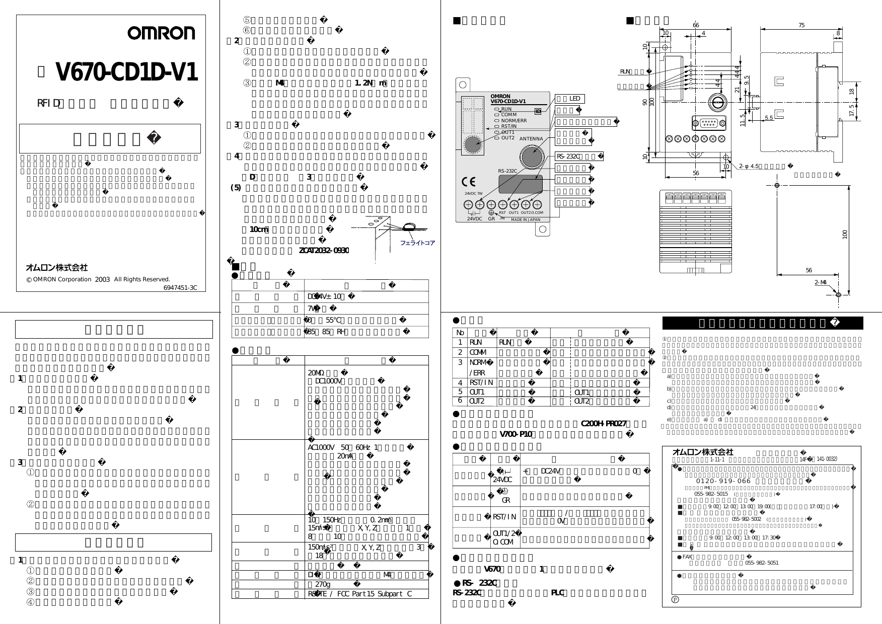
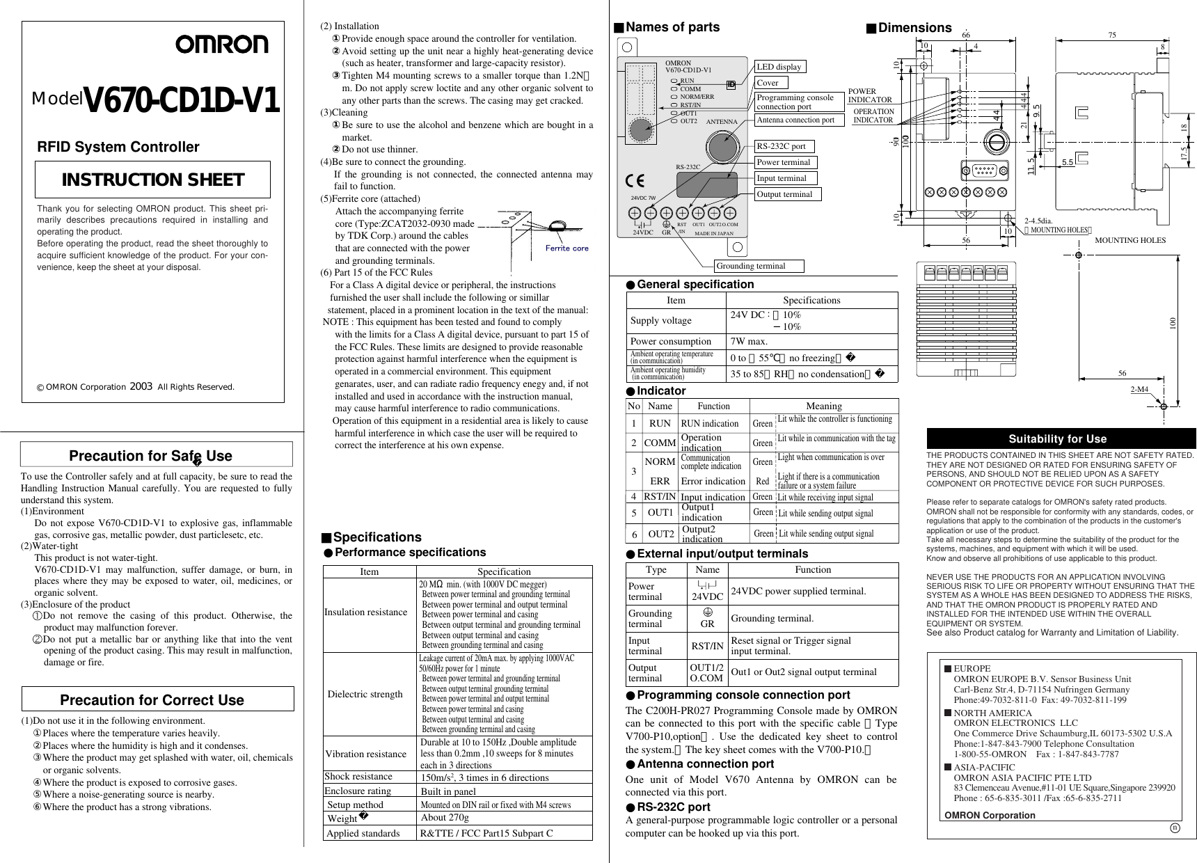
Omron 6CYCIDV6700206 RFID System User Manual V670 CD1D V1 6947451 3C J ai

Omron Corporation RFID System V670 CD1D V1 6947451 3C J ai

Contents

User Manual 1

安全上の要点安全に正しくご使用いただくために、お使いになる前に必ず「取扱い方法を記載したマニュアル」をお読みになり、十分に理解してください。(1)使用環境について爆発性ガス、引火性ガス、腐食性ガス、金属粉、粉じん等のあるところでは使用しないでください。(2)防水についてこの製品は防水タイプではありません。そのため、水・油・薬品・有機溶剤がかかる環境では、製品の誤動作、損傷または発火につながる可能性があります。(3)製品の構造について この製品のケースは取り外さないようにしてください。取り外した場合、性能を果たさなくなる可能性があります。 製品ケースの通風口から金属棒等を差し込まないでください。製品の誤動作・損傷または発火につながる可能性があります。 ノイズの発生源周辺 激しい振動が加わる場所(2)取り付けについて 通風スペースを十分とってください。 発熱量の高い機器(ヒータ、トランス、大容量の抵抗)の近くに取り付けることは避けてください。 取付穴M4のネジ締めトルクは1.2N・m以下としてください。また、ネジロック剤等の有機溶剤はネジ締め部には塗装しないでください。ケースに割れが発生する可能性があります。(3)清掃について 市販のアルコールまたはベンジンをご使用ください シンナー類は使用しないでください。(4)アース線の接地は必ず行ってください。接地しない場合は接続したアンテナが正常動作しなくなります。    (D種接地工事 第3種接地工事) (5) 付属品のフェライトコアについて  付属品のフェライトコアは電源用端子、接地用端子に接続したコードに束ねて必ず接続してください。フェライトコアと製品本体は    約10cm離してください。  フェライトコア形式:  TDK(株)製 ZCAT2032-0930当社製プログラミングコンソール形C200H-PR027を接続ケーブル(形V700-P10別売)にて接続可能です。RS-232C準拠により、汎用のPLCやパソコンと接続することができます。当社製形V670アンテナを1台接続可能です。使用上の注意(1)下記の環境では使用しないでください。 温度変化の激しい場所 湿度が高く、結露の生じる恐れのある場所 水・油・薬品・有機溶剤がかかる場所 腐食性ガスがある場所■仕様■各部の名称 ■外形寸法●一般仕様●表示灯●電源・外部入出力端子●プロコン接続ポート●RS‐232Cポート●アンテナ接続ポート●性能仕様電源電圧消費電力使用周囲温度(交信時)使用周囲湿度(交信時)仕    様DC24V±10%7W以下0∼+55℃(氷結なきこと)35∼85%RH(結露なきこと)項  目絶縁抵抗耐電圧耐振動耐衝撃構造取付方法仕    様20MΩ以上(DC1000Vメガにて)電源・入力端子一接地端子間電源・入力端子一出力端子間電源・入力端子一ケース間出力端子一接地端子間出力端子一ケース間接地端子一ケース間AC1000V 50/60Hz 1分間にて漏れ電流20mA以下電源・入力端子一接地端子間電源・入力端子一出力端子間電源・入力端子一ケース間出力端子一接地端子間出力端子一ケース間接地端子一ケース間10∼150Hz、複振幅0.2mm、加速度15m/s2の振動をX,Y,Z各方向に1掃引8分間で10掃引印加し異常ないこと150m/s2の衝撃をX,Y,Z各方向に各3回計18回印加し異常ないこと盤内蔵型DINレール取付けまたはM4ネジ締付け項  目電源用端子接地用端子入力端子名称 24VDC GRRST/INOUT1/2O.COM機       能+側にDC24V電源を供給し、他方に0Vを接続します。接地用端子です。(D種接地)外部リセット入力/外部トリガ入力を使用時、電源用端子0Vと対になって使用します。外部出力を使用する場合に使用します。種類66 751817.5810 21 44456 2-φ4.5(取付穴) 取付穴加工方法RUN表示灯動作表示灯2-M4561004101010 10090OMRON V670-CD1D-V1RUNCOMMNORM/ERRRST/INRS-232C24VDC GR RST/IN OUT2MADE IN JAPANO.COMANTENNA表示LEDカバープロコン接続ポートアンテナ接続ポートRS-232Cポート電源用端子入力用端子出力用端子接地用端子1234名称RUNCOMMNORM機能RUN表示動作状態表示通信完了表示意    味緑色 正常動作時点灯緑色 タグとの交信中に点灯緑色 交信正常終了時に点灯No/ERR エラー表示 赤色 エラー発生時に点灯RST/IN 入力表示 緑色 信号入力時に点灯OUT1 出力表示 緑色 OUT1出力時に点灯5OUT2 出力表示6緑色 OUT2出力時に点灯出力端子OUT1OUT2OUT144+24VDC 7WID9.511.55.5 質量約270g適応規格R&TTE / FCC Part15 Subpart C© OMRON Corporation              All Rights Reserved. 取扱説明書このたびは、本製品をお買い上げいただきまして、まことにありがとうございます。ご使用に際しては、次の内容をお守りください。 ・電気の知識を有する専門家が扱ってください。 ・この取扱説明書をよくお読みになり、十分にご理解のうえ  正しくご使用ください。 ・この取扱説明書はいつでも参照できるよう大切に保管くだ  さい。 ・詳細につきましては、ユーザーズマニュアルをご参照ください。6947451-3C2003  形 V670-CD1D-V1  RFIDシステム コントローラご使用に際してのご承諾事項           営業統轄事業部東京都品川区大崎1-11-1 ゲートシティ大崎ウエストタワー14F①安全を確保する目的で直接的または間接的に人体を検出する用途に、本製品を使用しないでください。同用途には、当社センサカタログに掲載している安全センサをご使用ください。②下記用途に使用される場合、当社営業担当者までご相談のうえ仕様書などによりご確認いただくとともに、定格・性能に対し余裕を持った使い方や、万一故障があっても危険を最小にする安全回路などの安全対策  a)屋外の用途、潜在的な化学的汚染あるいは電気的妨害を被る用途  またはカタログ、取扱説明書等に記載のない条件や環境での使用  b)原子力制御設備、焼却設備、鉄道・航空・車両設備、医用機械、娯楽機械、  安全装置、および行政機関や個別業界の規制に従う設備  c)人命や財産に危険が及びうるシステム・機械・装置  d)ガス、水道、電気の供給システムや24時間連続運転システムなどの  高い信頼性が必要な設備  e)その他、上記 a) ∼ d) に準ずる、高度な安全性が必要とされる用途    *上記は適合用途の条件の一部です。当社のベスト、総合カタログ・データシート等最新版の    カタログ、マニュアルに記載の保証・免責事項の内容をよく読んでご使用ください。●営業にご用の方も、技術的なお問い合せの方も、フリーコールにお電話ください。音声ガイダンスが流れますので、案内に従って操作ください。  0120-919-066 (フリーコール)携帯電話・PHSなどではご利用いただけませんので、その場合は下記電話番号へおかけください。055-982-5015   (通話料がかかります)〔技術のお問い合わせ時間〕■営業時間:9:00∼12:00/13:00∼19:00(土・日・祝祭日は17:00まで)■営 業 日 :年末年始休暇を除く上記フリーコール以外に 055-982-5002   (通話料がかかります)におかけいただくことにより、直接センシング機器の技術窓口につながります。〔営業のお問い合わせ時間〕■営業時間:9:00∼12:00/13:00∼17:30■営 業 日 :土・日・祝祭日/春期・夏期・年末年始休暇を除く●FAXによるお問い合わせはお客様相談室 FAX055-982-5051●その他のお問い合せ先納期・価格・修理・サンプル・承認図は貴社のお取引先、または貴社担当オムロン営業員にご相談ください。(〒141-0032)p
1009044Precaution for Safe UseTo use the Controller safely and at full capacity, be sure to read the Handling Instruction Manual carefully. You are requested to fully understand this system. (1)Environment Do not expose V670-CD1D-V1 to explosive gas, inflammable gas, corrosive gas, metallic powder, dust particlesetc, etc. (2)Water-tight This product is not water-tight. V670-CD1D-V1 may malfunction, suffer damage, or burn, in places where they may be exposed to water, oil, medicines, or organic solvent. (3)Enclosure of the product  Do not remove the casing of this product. Otherwise, the product may malfunction forever.  Do not put a metallic bar or anything like that into the vent opening of the product casing. This may result in malfunction, damage or fire.(2) Installation ①Provide enough space around the controller for ventilation. ②Avoid setting up the unit near a highly heat-generating device (such as heater, transformer and large-capacity resistor). ③Tighten M4 mounting screws to a smaller torque than 1.2N・m. Do not apply screw loctite and any other organic solvent to any other parts than the screws. The casing may get cracked. (3)Cleaning ①Be sure to use the alcohol and benzene which are bought in a market. ②Do not use thinner. (4)Be sure to connect the grounding. If the grounding is not connected, the connected antenna may fail to function.(5)Ferrite core (attached)      Attach the accompanying ferrite      core (Type:ZCAT2032-0930 made      by TDK Corp.) around the cables      that are connected with the power      and grounding terminals.(6) Part 15 of the FCC Rules    For a Class A digital device or peripheral, the instructions       furnished the user shall include the following or simillar    statement, placed in a prominent location in the text of the manual: NOTE : This equipment has been tested and found to comply       with the limits for a Class A digital device, pursuant to part 15 of       the FCC Rules. These limits are designed to provide reasonable       protection against harmful interference when the equipment is       operated in a commercial environment. This equipment       genarates, user, and can radiate radio frequency enegy and, if not       installed and used in accordance with the instruction manual,       may cause harmful interference to radio communications.      Operation of this equipment in a residential area is likely to cause       harmful interference in which case the user will be required to       correct the interference at his own expense.A general-purpose programmable logic controller or a personal computer can be hooked up via this port.One unit of Model V670 Antenna by OMRON can be connected via this port.■Specifications■Names of parts ■Dimensions●Indicator●External input/output terminals●RS-232C port●Antenna connection port●Performance specificationsPowerterminalGroundingterminal InputterminalOutputterminalName 24VDC GRRST/INOUT1/2O.COMFunction24VDC power supplied terminal.Grounding terminal.Reset signal or Trigger signalinput terminal.Out1 or Out2 signal output terminal Type66 751817.5810 21 4 4 4562-4.5dia.(MOUNTING HOLES)POWERINDICATOROPERATIONINDICATORMOUNTING HOLES2-M456100101010 10090OMRON V670-CD1D-V1RUNCOMMNORM/ERRRST/INRS-232C24VDC GRRST/INOUT1MADE IN JAPANO.COMANTENNALED displayCoverProgramming consoleconnection portAntenna connection portRS-232C portPower terminalInput terminalOutput terminalGrounding terminalModelV670-CD1D-V123COMMNORMERROperation indicationCommunicationcomplete indicationError indicationLit while the controller is functioning Lit while in communication with the tagLight when communication is overLight if there is a communication failure or a system failureGreenGreenRed1NameRUNFunctionRUN indicationMeaningGreenNoInsulation resistanceDielectric strengthVibration resistanceSpecification20 MΩ min. (with 1000V DC megger) Between power terminal and grounding terminalBetween power terminal and output terminalBetween power terminal and casingBetween output terminal and grounding terminalBetween output terminal and casingBetween grounding terminal and casingLeakage current of 20mA max. by applying 1000VAC50/60Hz power for 1 minuteBetween power terminal and grounding terminal Between output terminal grounding terminalBetween power terminal and output terminalBetween power terminal and casingBetween output terminal and casingBetween grounding terminal and casingDurable at 10 to 150Hz ,Double amplitudeless than 0.2mm ,10 sweeps for 8 minuteseach in 3 directionsItemShock resistanceEnclosure ratingSetup methodWeight150m/s2, 3 times in 6 directionsBuilt in panelMounted on DIN rail or fixed with M4 screwsAbout 270g4 RST/IN Input indicationLit while receiving input signalGreenOUT1 Output1  indicationLit while sending output signalGreen5OUT2 Output2  indicationLit while sending output signalGreen6The C200H-PR027 Programming Console made by OMRON can be connected to this port with the specific cable (Type V700-P10,option). Use the dedicated key sheet to control the system.(The key sheet comes with the V700-P10.)●Programming console connection portOUT1OUT2OUT29.511.55.5 4●General specificationSupply voltagePower consumptionAmbient operating temperature(in communication)Ambient operating humidity (in communication)Specifications24V DC : +10%−10%7W max. 0 to +55℃(no freezing)35 to 85%RH(no condensation)ItemID24VDC 7W(1)Do not use it in the following environment.①Places where the temperature varies heavily.②Places where the humidity is high and it condenses. ③Where the product may get splashed with water, oil, chemicals or organic solvents.④Where the product is exposed to corrosive gases. ⑤Where a noise-generating source is nearby.⑥Where the product has a strong vibrations.Precaution for Correct UseApplied standards R&TTE / FCC Part15 Subpart CSuitability for UseTHE PRODUCTS CONTAINED IN THIS SHEET ARE NOT SAFETY RATED.  THEY ARE NOT DESIGNED OR RATED FOR ENSURING SAFETY OF PERSONS, AND SHOULD NOT BE RELIED UPON AS A SAFETY COMPONENT OR PROTECTIVE DEVICE FOR SUCH PURPOSES.  Please refer to separate catalogs for OMRON's safety rated products.OMRON shall not be responsible for conformity with any standards, codes, or regulations that apply to the combination of the products in the customer's application or use of the product.Take all necessary steps to determine the suitability of the product for the systems, machines, and equipment with which it will be used.Know and observe all prohibitions of use applicable to this product. NEVER USE THE PRODUCTS FOR AN APPLICATION INVOLVING SERIOUS RISK TO LIFE OR PROPERTY WITHOUT ENSURING THAT THE SYSTEM AS A WHOLE HAS BEEN DESIGNED TO ADDRESS THE RISKS, AND THAT THE OMRON PRODUCT IS PROPERLY RATED AND INSTALLED FOR THE INTENDED USE WITHIN THE OVERALL EQUIPMENT OR SYSTEM.See also Product catalog for Warranty and Limitation of Liability.OMRON CorporationEUROPEOMRON EUROPE B.V. Sensor Business UnitCarl-Benz Str.4, D-71154 Nufringen GermanyPhone:49-7032-811-0  Fax: 49-7032-811-199NORTH AMERICAOMRON ELECTRONICS  LLCOne Commerce Drive Schaumburg,IL 60173-5302 U.S.APhone:1-847-843-7900 Telephone Consultation1-800-55-OMRON    Fax : 1-847-843-7787ASIA-PACIFICOMRON ASIA PACIFIC PTE LTD83 Clemenceau Avenue,#11-01 UE Square,Singapore 239920Phone : 65-6-835-3011 /Fax :65-6-835-2711n© OMRON Corporation              All Rights Reserved.INSTRUCTION SHEETThank you for selecting OMRON product. This sheet pri-marily describes precautions required in installing andoperating the product.Before operating the product, read the sheet thoroughly toacquire sufficient knowledge of the product. For your con-venience, keep the sheet at your disposal.2003RFID System Controller

Navigation menu