Omron 6CYCIDV6700206 RFID System User Manual Z148 E1 04
Omron Corporation RFID System Z148 E1 04
Omron >
Contents
- 1. User Manual 1
- 2. User Manual 2
User Manual 2

Electromagnetic Inductive RFID System
V670 Series
User’s Manual
ID Controller, Antenna, and ID Tag
ID Controller
Model V670-CD1D-V1
Antenna
Model V670-H11
Model V670-H51
Model V670-H51Q
ID Tag
Model V670-D13F03
Model V670-D13F01
Model V670-D13F01H
Catalog No. Z148-E1-04
Introduction
We sincerely appreciate your purchase of the V670 series of the Electromagnetic Induction Type RFID System. The V670 series is fully
supported by our cutting-edge technology and vast expertise. This user's manual provides vital information on its operational functions
and product performances, and includes full instructions for use.

READ AND UNDERSTAND THIS DOCUMENT
Please read and understand this document before using the products. Please consult your OMRON representative if you have any
questions or comments.
WARRANTY
OMRON’s exclusive warranty is that the products are free from defects in materials and workmanship for a period of one year (or
other period if specified) from date of sale by OMRON.
OMRON MAKES NO WARRANTY OR REPRESENTATION, EXPRESS OR IMPLIED, REGARDING NON-INFRINGEMENT,
MERCHANTABILITY, OR FITNESS FOR PARTICULAR PURPOSE OF THE PRODUCTS. ANY BUYER OR USER
ACKNOWLEDGES THAT THE BUYER OR USER ALONE HAS DETERMINED THAT THE PRODUCTS WILL SUITABLY MEET
THE REQUIREMENTS OF THEIR INTENDED USE. OMRON DISCLAIMS ALL OTHER WARRANTIES, EXPRESS OR IMPLIED.
LIMITATIONS OF LIABILITY
OMRON SHALL NOT BE RESPONSIBLE FOR SPECIAL, INDIRECT, OR CONSEQUENTIAL DAMAGES, LOSS OF PROFITS
OR COMMERCIAL LOSS IN ANY WAY CONNECTED WITH THE PRODUCTS, WHETHER SUCH CLAIM IS BASED ON
CONTRACT, WARRANTY, NEGLIGENCE, OR STRICT LIABILITY.
In no event shall responsibility of OMRON for any act exceed the individual price of the product on which liability is asserted.
IN NO EVENT SHALL OMRON BE RESPONSIBLE FOR WARRANTY, REPAIR, OR OTHER CLAIMS REGARDING THE
PRODUCTS UNLESS OMRON’S ANALYSIS CONFIRMS THAT THE PRODUCTS WERE PROPERLY HANDLED, STORED,
INSTALLED, AND MAINTAINED AND NOT SUBJECT TO CONTAMINATION, ABUSE, MISUSE, OR INAPPROPRIATE
MODIFICATION OR REPAIR.
SUITABILITY FOR USE
THE PRODUCTS CONTAINED IN THIS DOCUMENT ARE NOT SAFETY RATED. THEY ARE NOT DESIGNED OR RATED FOR
ENSURING SAFETY OF PERSONS, AND SHOULD NOT BE RELIED UPON AS A SAFETY COMPONENT OR PROTECTIVE
DEVICE FOR SUCH PURPOSES. Please refer to separate catalogs for OMRON's safety rated products.
OMRON shall not be responsible for conformity with any standards, codes, or regulations that apply to the combination of products
in the customer’s application or use of the product.
At the customer’s request, OMRON will provide applicable third party certification documents identifying ratings and limitations of
use that apply to the products. This information by itself is not sufficient for a complete determination of the suitability of the
products in combination with the end product, machine, system, or other application or use.
The following are some examples of applications for which particular attention must be given. This is not intended to be an
exhaustive list of all possible uses of the products, nor is it intended to imply that the uses listed may be suitable for the products:
• Outdoor use, uses involving potential chemical contamination or electrical interference, or conditions or uses not described in this
document.
• Nuclear energy control systems, combustion systems, railroad systems, aviation systems, medical equipment, amusement
machines, vehicles, safety equipment, and installations subject to separate industry or government regulations.
• Systems, machines, and equipment that could present a risk to life or property.
Please know and observe all prohibitions of use applicable to the products.
NEVER USE THE PRODUCTS FOR AN APPLICATION INVOLVING SERIOUS RISK TO LIFE OR PROPERTY WITHOUT
ENSURING THAT THE SYSTEM AS A WHOLE HAS BEEN DESIGNED TO ADDRESS THE RISKS, AND THAT THE OMRON
PRODUCT IS PROPERLY RATED AND INSTALLED FOR THE INTENDED USE WITHIN THE OVERALL EQUIPMENT OR
SYSTEM.
PERFORMANCE DATA
Performance data given in this document is provided as a guide for the user in determining suitability and does not constitute a
warranty. It may represent the result of OMRON’s test conditions, and the users must correlate it to actual application requirements.
Actual performance is subject to the OMRON Warranty and Limitations of Liability.
CHANGE IN SPECIFICATIONS
Product specifications and accessories may be changed at any time based on improvements and other reasons.
It is our practice to change model numbers when published ratings or features are changed, or when significant construction
changes are made. However, some specifications of the product may be changed without any notice. When in doubt, special model
numbers may be assigned to fix or establish key specifications for your application on your request. Please consult with your
OMRON representative at any time to confirm actual specifications of purchased products.
DIMENSIONS AND WEIGHTS
Dimensions and weights are nominal and are not to be used for manufacturing purposes, even when tolerances are shown.
ERRORS AND OMISSIONS
The information in this document has been carefully checked and is believed to be accurate; however, no responsibility is assumed
for clerical, typographical, or proofreading errors, or omissions.
PROGRAMMABLE PRODUCTS
OMRON shall not be responsible for the user’s programming of a programmable product, or any consequence thereof.
COPYRIGHT AND COPY PERMISSION
This document shall not be copied for sales or promotions without permission. This document is protected by copyright and is
intended solely for use in conjunction with the product. Please notify us before copying or reproducing this document in any
manner, for any other purpose. If copying or transmitting this document to another, please copy or transmit it in its entirety.
The following signal words are used in this instruction manual.
The following alert symbols are used in this instruction manual.
The following alert statements apply to the products in this instruction manual. Each alert statement also appears at the locations needed
in the manual to attract your attention.
Meaning of Signal Words
CAUTION Indicates a potentially hazardous situation which, if not avoided, may result in minor or
moderate injury or in property damage.
Meaning of Alert Symbols
Indicates the possibility of electric shock under specific conditions.
Alert Statement in this user’s Manual
CAUTION
When you plug or unplug the connector into the programming console when the power supply turns on, take care not to
touch the controller wire. Otherwise, you may get an electric shock.

For the safety, be sure to follow the instructions below:
1. Do not operate this device in any flammable, explosive or corrosive gas environment.
2. Do not disassemble, repair nor remodel this device.
3. Tighten the base lock screws and terminal block screws completely.
4. Be sure to use wiring crimp terminal of a specified size.
5. If any cable has a locking mechanism, be sure to check that it has been locked before using it.
6. The DC power supply must meet the following items:
(1) Such DC power supply must be used for the V670 Series only and must not be connected to any other devices nor apparatuses.
(2) Voltage of such DC power supply must be within the specified rating (24 VDC+10%-10%).
7. Be sure to follow any other warnings, cautions and notices mentioned in this manual.
8. In the event that the system gives out a foul smell, is heated abnormally in the main body portion, emits smoke, or exhibits any other
abnormal condition, immediately stop using the system and turn off the power.
9. Dispose of this product as industrial waste.
Please observe the following precautions to prevent failure to operate, malfunctions, or undesirable effects on product performance.
♦System Construction
• In consequence of diversification of small-size antennas/tags, the ID controller has been upgraded to Model V670-CD1D-V1. Be
sure to combine Model V670-H51 or Model V670-H51Q antenna with Model V670-CD1D-V1 controller. Combination of this
antenna with Model V670-CD1D controller might result in unstable communication.
♦Installation Site
Install the product at a location where:
• It is not exposed to corrosive gases, dust, metal chips, or salt.
• The working temperature is within the range stipulated in the specifications.
• There are no sudden variations in temperature (no condensation).
• The relative humidity is within the range stipulated in the specifications.
• No vibration or shock exceeding the values stipulated in the specifications is transmitted directly to the body of the product.
• It is not subject to splashing water, oil, or chemical substances.
♦Installation
• This device uses the frequency band 13.56 MHz to communicate with a tag. This frequency band 13.56 MHz is used also as the
ISM band (one of frequencies assigned to medical or industrial heater; ). So, such heater may affect the communication with a tag
or may damage the tag, if the heater is located near this device. If you must use this device near such heater, we would like you to
check the influence in advance.
• To minimize general influence of noise, follow the instructions below:
(1) Ground any metallic material located around this device according to Class D (Class III).
(2) Wire this device keeping away from high voltage and heavy current.
• Connectors are not waterproof. Avoid using the product in a humid environment.
• Do not use any chemical that may affect the materials of the product.
♦Cleaning
• Do not use any thinner. Resin material and case paint are dissolved by thinner.
Precautions for safe use.
Precautions for correct use.
1. FCC Rules (Federal Communications Commission)
This Product complies with Part 15 Subpart C of the FCC Rules.
FCC ID: E4E6CYCIDV6700206
FCC NOTICE
This device complies with part 15 of the FCC Rules. Operation is subject to the following two conditions:
(1) This device may not cause harmful interference.
(2) This device must accept any interference received, including interference that may cause undesired operation.
FCC WARNING
Changes or modifications not expressly approved by the party responsible for compliance could void the user's authority to operate
the equipment.
Properly shielded ground cables and connectors must be used for connection to host computer and/or peripherals in order to meet
FCC emission limits.
Ferrite cores (TDK Type ZCAT2032-0930 or its equivalent) must be attached to the cables connecting the power supply and ground
to suppress RF interference.
2. EC Declaration of Conformity
Hereby, OMRON Corporation declares that this RFID System, Antenna V670-H11, V670-H51, V670-H51Q and Controller V670-
CD1D-V1. Controller are in compliance with essential requirements and other relevant provisions of Directive 1995/5/EC, and sat-
isfy tests for the appropriate requirements of the following relevant standards.
Radio: EN 300 330-2 V1.1.1 (06-2001) EN 300 300-1 V1.3.1 (06-2001)
EMC: EN 301 489-3 V1.4.1 (08-2002) EN 301 489-1 V1.4.1 (08-2002)
Safety: EN 61010-1: 2001 (2nd Edition)
Countries of intended use:
Austria, Belgium, Denmark, Estonia, Finland, France, Germany, Greece, Iceland, Ireland, Italy, Liechtenstein, Luxembourg, Nether-
lands, Norway, Portugal, Romania, Spain, Sweden, Switzerland, United Kingdom
Changes or modifications not expressly approved by the party responsible for compliance could void the user's authority to operate
the equipment.
Properly shielded ground cables and connectors must be used for connection to host computer and/or peripherals in order to meet the
FCC emission limits.
Ferrite cores (TDK Type ZCAT2032-0930 or its equivalent) must be attached to the cables connecting the power supply and ground
to suppress RF interference.
Standard Conformity
English Hereby, Omron, declares that the RFID System, Antenna V670-H11 Series, V670-H51 Series, V670-H51Q Series, and Controller V670-CD1D Series are
in compliance with the essential requirements and other relevant provisions of Directive 1999/5/EC.
Finnish Omron vakuuttaa täten että RFID Säännös, Antenni V670-H11 Series, V670-H51 Series, V670-H51Q Series, jar Kontrollida V670-CD1D Series tyyp-
pinen laite on direktiivin 1999/5/EY oleellisten vaatimusten ja sitä koskevien direktiivin muiden ehtojen mukainen.
Dutch Hierbij verklaart Omron dat het toestel de RFID Systeem, Antenne V670-H11 ´Serie, V670-H51 ´Serie, V670-H51Q ´Serie, en Controleur V670-CD1D
´Serie in overeenstemming is met de essentiële eisen en de andere relevante bepalingen van richtlijh 1999/5/EG.
French Par la présente Omron déclare que la RFID Système, Antenne V670-H11 Série, V670-H51 Série, V670-H51Q Série, et Contrôler V670-CD1D Série sont
conforme aux exigences essentielles et aux autres dispositions pertinentes de la directive 1999/5/CE.
Swedish Härmed intygar Omron att den RFID System, Antenn V670-H11 Serie, V670-H51 Serie, V670-H51Q Serie, och Kontrollant V670-CD1D Serie stär l öve-
rensstämmelse med de väsentliga egenskapskrav och övriga relevanta bestämmelser som framgår av direktiv 1999/5/EG.
Danish Undertegnede Omron erklærer herved, at følgende den RFID System, Antenne V670-H11 Serie, V670-H51 Serie, V670-H51Q Serie, og Kontrollør V670-
CD1D Serie overholder de væsentlige krav og øvrige relevante krav i direktiv 1999/5/EF.
German Hiermit erklärt Omron, die RFID System, Antenne V670-H11 Serie, V670-H51 Serie, V670-H51Q Serie, und Kontrolleur V670-CD1D Serie in Überein-
stimmung mit den grundlegenden Anforderungen und den anderen relevanten Vorschriften der Richtlinie 1999/5/EG befindet. (BMWi)
Greek ME THN PAPOYSA Omron DHLONEI RFID O
’YO
’GHMA, KEPAIA V670-H11 O
’EIPA, V670-H51Q O
’EIPA, KAI KOYPOLHPY V670-CD1D O
’EIPA
SYMMOPF ONETAI PPOS TIS OYSIODEIS APAITHSEIS KAI TIS LOIPES SXETIKES DIATAXEIS THS ODHGIAS 1999/5/EK.
Italian Con la presente Omron dichiara che la RFID Sistema, Antena V670-H11Serie, V670-H51 Serie, V670-H51Q Serie, e Controlleur V670-CD1D Serie sono
conforme ai requisiti essenziali ed alle altre disposizioni pertinenti stabilite dalla direttiva 1999/5/CE.
Spanish Por medio de la presente Omron declara que el RFID Sistema, Antena V670-H11 Serie, V670-H51 Serie, V670-H51Q Serie, y Controlador V670-CD1D
Serie esta conforme a los requisitos esenciales y cualesquiera otras disposiciones aplicables o exigibles de la Directiva 1999/5/CE.
Portuguese Omron declara que a RFID Sistema, Antena V670-H11 Série, V670-H51 Série, V670-H51Q Série, e Controlador V670-CD1D Série ser conforme com os
tequisitos essenciais e outras disposições da Directiva 1999/5/CE.
Romanian Prin prezenta, Omron declar c acest V670-H11, V670-H51, V670-H51Q, V670-CD1D este conform cu cerin ele principale çi cu celelalte prevederi
relevanate ale Directivei 1999/5/EC.
A manual revision history code is added to the end of catalog number shown at the left lower part of front cover
and back cover
Manual Revision History
Revision
Code
Date of
Revision Reason of Revision / Revised Page
-- October 2000 First Edition
-02 May 2003 New models have been added.
-03 March 2005 Prefix (Standard Conformity): Last line in FCC WARNING
description changed and sentence added after table.
Warranty and Limitations of Liability page updated.
Romania added to list of countries of intended use.
-04 January 2006 Pages 1-1, 2-1, 2-5, 2-6, 3-7, 3-10, 3-11, and appendix-2:
Mark removed from V670-CD1D-V1 graphic.
Page 2-3: Insulation resistance changed to "20 MΩ or
more (at 100 VDC mega)."
Page 2-3: Withstand voltage changed to "Leakage current
20 mA or less at 1,000 VAC (for 1 minute)."
Catalog No. Z148-E1-04
Revision code

Contents
Chapter 1 Features and System Configuration
1-1 Features .........................................................................................................................1-1
1-2 System Configuration.....................................................................................................1-3
Chapter 2 Specifications and Performance
2-1 Controller........................................................................................................................2-1
2-1-1 Component Names and Functions .....................................................................................................2-1
2-1-2 General Specifications ....................................................................................................................... 2-3
2-1-3 Performance Specifications................................................................................................................2-3
2-1-4 Communication Specifications ..........................................................................................................2-4
2-1-5 I/O Specifications...............................................................................................................................2-4
2-1-6 Example of Wiring............................................................................................................................. 2-5
2-1-7 Outside Dimension............................................................................................................................. 2-6
2-2 Antenna ..........................................................................................................................2-7
2-2-1 Specifications.....................................................................................................................................2-7
2-2-2 Outside Dimension............................................................................................................................. 2-8
2-3 Tag ..................................................................................................................................2-9
2-3-1 Specifications.....................................................................................................................................2-9
2-3-2 Outside Dimension........................................................................................................................... 2-10
2-3-3 Memory Map.................................................................................................................................... 2-11
2-3-4 Attachment (Model V670-A81) for Model V670-D13F01H Tag....................................................2-12
2-4 Cable.............................................................................................................................2-13
2-4-1 Specifications...................................................................................................................................2-13
2-4-2 Outside Dimension........................................................................................................................... 2-13
2-5 Communication Range Specifications .........................................................................2-14
2-5-1 Communication Area (Reference) ...................................................................................................2-15
2-5-2 Operation Time (Reference) ............................................................................................................2-17
2-5-3 Traffic and Passing Speed (Reference) ............................................................................................2-19

Contents
Chapter 3 Setting and Installation
3-1 Controller........................................................................................................................3-1
3-1-1 Switch Setting.................................................................................................................................... 3-1
3-1-1-1 How to Open Cover ................................................................................................................. 3-1
3-1-1-2 How to Set ............................................................................................................................... 3-2
3-1-1-3 Setting List............................................................................................................................... 3-2
3-1-1-4 Setting Node Number Setup Switch ........................................................................................ 3-3
3-1-1-5 Setting a Dip Switch ................................................................................................................ 3-4
3-1-2 Installation Site .................................................................................................................................. 3-6
3-1-3 How to Install..................................................................................................................................... 3-7
3-1-4 How to Connect Antenna................................................................................................................... 3-8
3-1-5 How to Connect Extension Cable and How to Extend Antenna ....................................................... 3-9
3-1-6 How to Wire....................................................................................................................................... 3-9
3-1-6-1 Wiring Power Supply and Grounding Cable ......................................................................... 3-10
3-1-6-2 Wiring Reset Signal ............................................................................................................... 3-10
3-1-6-3 Wiring Output Signal............................................................................................................. 3-11
3-1-7 Connecting RS-232C Interface........................................................................................................ 3-12
3-2 Antenna.........................................................................................................................3-16
3-2-1 Installation Site ................................................................................................................................ 3-16
3-2-2 How to Install................................................................................................................................... 3-16
3-3 Tag ................................................................................................................................3-18
3-3-1 Installation Site ................................................................................................................................ 3-18
3-3-2 How to Install................................................................................................................................... 3-18
Chapter 4 Functions
4-1 Communication Designation Function...........................................................................4-1
4-1-1 Designation of Command Trigger System Communication (ST) ..................................................... 4-1
4-1-2 Designation of Automatic System Communication (SA/RA/PA)..................................................... 4-2
4-1-3 Designation of External Trigger System Communication (SI/RI/PI)................................................ 4-3
4-2 Tag Designation Function...............................................................................................4-5
4-3 Operation Mode..............................................................................................................4-6
4-4 Operation Parameter Setting...........................................................................................4-8
4-4-1 Communication Restriction Time...................................................................................................... 4-8
4-4-2 Character Interval Monitoring Time.................................................................................................. 4-8
4-4-3 Response Ready Time........................................................................................................................ 4-9
4-5 Memory Check Function..............................................................................................4-10
4-6 Write Protect Function..................................................................................................4-11

Contents
Chapter 5 Control From Host Device
5-1 Controller Operation Status ...........................................................................................5-1
5-2 Command Response Format ..........................................................................................5-2
5-3 Command Response Flow..............................................................................................5-6
5-4 Command List ................................................................................................................5-7
5-5 Communication Designation List...................................................................................5-8
5-6 Communication Command.............................................................................................5-9
5-6-1 Read (RD) ........................................................................................................................................5-10
5-6-2 Write (WT)....................................................................................................................................... 5-11
5-6-3 Computation Write (CW).................................................................................................................5-12
5-6-4 Data Fill (DF)...................................................................................................................................5-13
5-6-5 Memory Check (MD).......................................................................................................................5-14
5-6-6 Tag Function Designation (TF)........................................................................................................5-15
5-6-7 ID Read (ID) ....................................................................................................................................5-16
5-7 Communication Subcommand .....................................................................................5-17
5-7-1 Command Processing Abort (AA)...................................................................................................5-17
5-7-2 Polling Query (PC)........................................................................................................................... 5-17
5-8 Controller Control Command.......................................................................................5-18
5-8-1 Operation Mode Change (MO)........................................................................................................5-18
5-8-2 Data Retransmission (RR) ...............................................................................................................5-18
5-8-3 Reset (XZ)........................................................................................................................................5-19
5-8-4 Controller Control (CC)...................................................................................................................5-19
5-8-5 Operation Condition Setting (SE)....................................................................................................5-20
5-8-6 Parameter Setting (SP)..................................................................................................................... 5-22
5-9 Host Command.............................................................................................................5-23
5-9-1 Test (TS)...........................................................................................................................................5-23
5-9-2 Version Information (VS).................................................................................................................5-23
5-10 Termination Code List..................................................................................................5-24
5-11 Example of Communication Program..........................................................................5-25

Contents
Chapter 6 How to Use Self-Execution Mode
6-1 Available Conditions ......................................................................................................6-1
6-2 Setting Procedure ...........................................................................................................6-2
6-3 Example of Setting .........................................................................................................6-3
Chapter 7 How to Use Programming Console
7-1 Component Name...........................................................................................................7-1
7-2 Outside Dimension .........................................................................................................7-2
7-3 Connection of Programming Console ............................................................................7-3
7-3-1 Inserting Key Sheet............................................................................................................................ 7-3
7-3-2 Connecting Cable............................................................................................................................... 7-4
7-4 How to Use .....................................................................................................................7-5
7-5 Functions ........................................................................................................................7-6
7-5-1 Programming Console Function List................................................................................................. 7-6
7-5-2 How to Operate.................................................................................................................................. 7-7
7-5-2-1 Password Input Screen............................................................................................................. 7-7
7-5-2-2 Changing Operation Mode....................................................................................................... 7-7
7-5-2-3 Accepting Key in Initial Screen of Monitor Mode .................................................................. 7-8
7-5-2-4 Accepting Key in Initial Screen of Run Mode ........................................................................ 7-9
7-5-3 Displaying Details of Setting........................................................................................................... 7-10
7-5-4 Address Setting................................................................................................................................ 7-12
7-5-4-1 For Reading............................................................................................................................ 7-12
7-5-4-2 For Writing............................................................................................................................. 7-12
7-5-5 Data Setting...................................................................................................................................... 7-13
7-5-6 Reading/Writing Data ...................................................................................................................... 7-13
7-5-6-1 Reading .................................................................................................................................. 7-13
7-5-6-2 Reading Again ....................................................................................................................... 7-14
7-5-6-3 Writing ................................................................................................................................... 7-15
7-5-6-4 Writing Again ........................................................................................................................ 7-15
7-5-7 Test................................................................................................................................................... 7-16
7-5-7-1 Setting Communication Mode...............................................................................................7-16
7-5-7-2 Test Reading........................................................................................................................... 7-16
7-5-7-3 Test Writing............................................................................................................................ 7-16
7-5-8 Reading Latest Error Information.................................................................................................... 7-17
7-5-9 Statistic Error Information............................................................................................................... 7-18
7-5-10 Execution Monitor........................................................................................................................... 7-19

Contents
Chapter 8 From Startup to Run
8-1 Trial Operation ...............................................................................................................8-1
8-2 Diagnosis Function.........................................................................................................8-2
8-3 Errors and Countermeasures...........................................................................................8-3
8-4 Maintenance and Inspection...........................................................................................8-4
8-5 Troubleshooting..............................................................................................................8-5
Chapter 9 Characteristic Data Depending on Operating Condition
(Reference)
9-1 Influence of Metal of Antenna (Reference)....................................................................9-1
9-2 Mutual Interference between Antennas (Reference)......................................................9-3
9-3 Mutual Interference between Tags (Reference) .............................................................9-4
9-4 Influence of Back Metal of Tag (Reference)..................................................................9-5
9-5 Influence of Tag Angle (Reference) ...............................................................................9-7
9-6 Chemical Resistance of Tag (Reference) .......................................................................9-8
Appendix
Appendix 1 ASCII Code List ............................................................................... Appendix-1
Appendix 2 Order Format List ............................................................................. Appendix-2
Appendix 3 Protective Structure........................................................................... Appendix-3
1-1
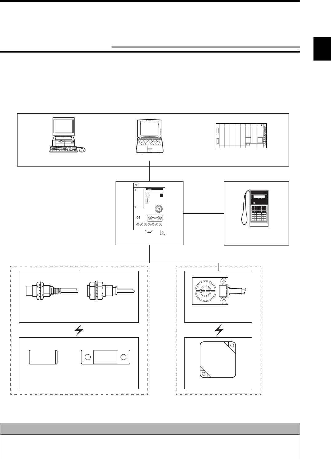
The V670 Series is the electromagnetic inductive. RFID system which has achieved fast, long-life and high-performance communica-
tion. This ID system is the most suitable for process control of high-speed line and traffic control of moving object in a plant and an
application that information must be updated frequently in a process.
♦ID Controller (referred to as “Controller”)
•Model V670-CD1D-V1
Model V670-CD1D-V1 connects to a personal computer (referred to as "PC") and/or programmable controller (PLC) and controls
the RFID system.
Model V670-CD1D-V1 has a general-purpose I/O terminal and a function to judge and process independently (Self-Execution
mode) and, therefore, a very fast system can be configured for simple process only without any host device.
♦Antenna (referred to as “Antenna”)
•Model V670-H11
Model V670-H11 is a waterproof antenna (standard antenna) with dimensions of 4 × 5.3 cm. Model V670-H11 can achieve the com-
munication range of 20 mm in combination with model V670-D13F03. Model V670-H11 has a very fast communication perfor-
mance and can transfer 12 bytes of data in approximately 5 ms.
•Model V670-H51
Model V670-H51 is a cylindrically-shaped waterproof antenna. Model V670-H51 can achieve a communication range of 5.0 mm
when combined with Model V670-D13F01 or V670-D13F01H tag. Model V670-H51 has a communication performance as high as
that of Model V670-H11.
•Model V670-H51Q
Model V670-H51Q is a cylindrically-shaped antenna. Housed in a Teflon (tetrafluoroethylene) casing, Model V670-H51Q is highly
resistant to chemicals. Model V670-H51Q can achieve a communication range of 4.5 mm when combined with Model V670-
D13F01 or V670-D13F01H tag. Model V670-H51Q has a communication performance as high as that of Model V670-H11.
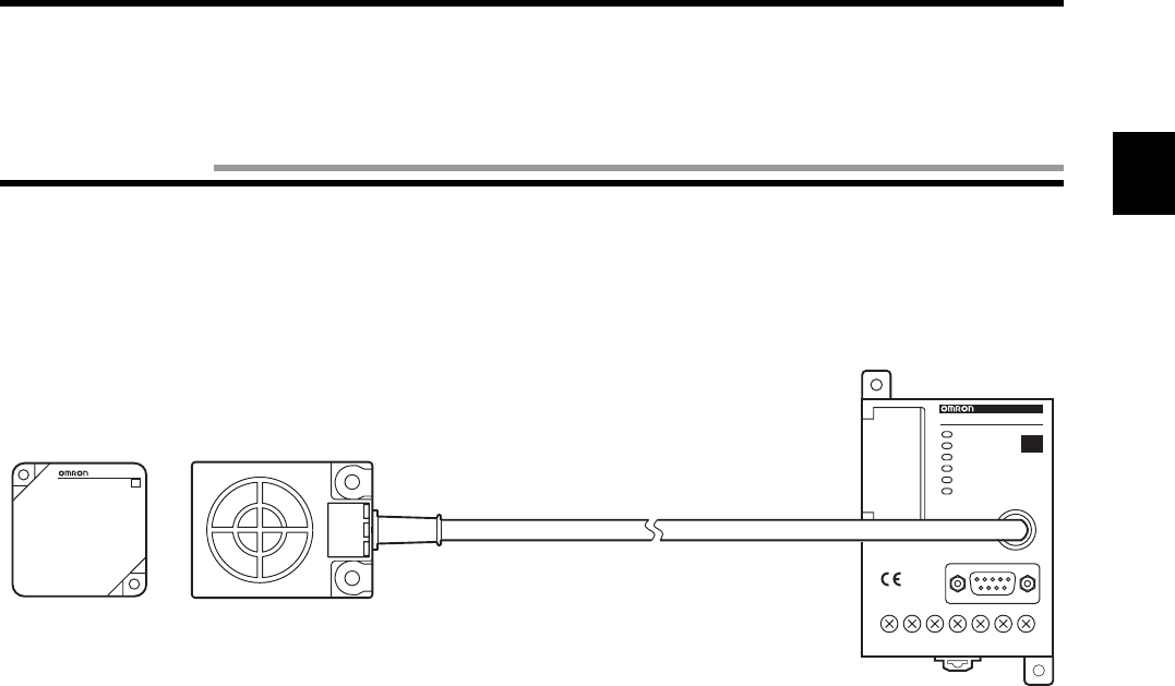
V6 7 0 - CD1 D
V670-CD1D-V1
ID
V670-D13F03
ID
Model V670-D13F03 Model V670-H11
Model V670-CD1D-V1
Chapter 1 Features and System Configuration
1-1 Features

1-1 Features
1-2
♦ID tag (referred to as “Tag”)
•Model V670-D13F03
Model V670-D13F03 is a waterproof tag which has 128 bytes of memory capacity with dimensions of 40 × 40 mm. Model V670-
D13F03 uses high-performance nonvolatile memory called Ferroelectric RAM (FeRAM) as internal memory. So, memory life is
semi-permanent. (The memory can be accessed one billion times.)
•Model V670-D13F01
Model V670-D13F01 is a rectangular tag with dimensions of 8 mm × 16 mm. Model V670-D13F01 is highly resistant to chemicals
since it is housed in a PPS casing filled with chemical-resistant epoxy resin. Model V670-D13F01 has the same memory capacity
and characteristics as those of Model V670-D13F03.
•Model V670-D13F01H
Model V670-D13F01H is a tag provided with screw holes to assure the same performance and construction as those of Model V670-
D13F01, and is easy to install.
•Model V670-A81
Model V670-A81 is an attachment specially designed for Model V670-D13F01H. When combined with Model V670-A81, Model
V670-D13F01H retains its original communication range even when fitted to a steel structure. Made of PPS, Model V670-A81 is
highly resistant to chemicals.
♦Easy to use
By connecting the programming console model C200H-PRO27 (unbundled, referred to as "ProCon") to the Controller via the special
cable model V700-P10 (unbundled), the system operation status and error log information can be read. This is useful for system star-
tup and maintenance at a working site.
Ferroelectric RAM (FeRAM)
Ferroelectric RAM is one of nonvolatile RAMs and data can be written into and read from it faster than conventional memory (such
as EEPROM and flash ROM). Data can be written into the ferroelectric RAM semi-permanently.
While any conventional RAM cannot hold data if nothing is written into it for a specified period (approximately 10 years), the ferro-
electric RAM can hold data if anything is written into or read from it. So, the characteristic of ferroelectric RAM is very excellent in
data-holding performance.
Precaution for Correct use
In consequence of diversification of small-size antennas/tags, the ID controller has been upgraded to Model V670-CD1D-V1. Be
sure to combine Model V670-H51 or Model V670-H51Q antenna with Model V670-CD1D-V1 controller. Combination of this
antenna with Model V670-CD1D controller might result in unstable communication.
1-3
•Example of Model V670-CD1D-V1 system configuration
Model V670-CD1D-V1 contains a serial interface based on RS-232C and can connect easily to a general-purpose PC and program-
mable controller (PLC). Model V670-CD1D-V1 has a command execution mode and self-execution mode as an operation mode and
controls the communication to a tag according to the instructions from a host device (in the command execution mode) or the regis-
tered conditions (in the self-execution mode).
<Host Devices>
Precaution for Correct use
In consequence of diversification of small-size antennas/tags, the ID controller has been upgraded to Model V670-CD1D-V1. Be
sure to combine Model V670-H51 or Model V670-H51Q antenna with Model V670-CD1D-V1 controller. Combination of this
antenna with Model V670-CD1D controller might result in unstable communication.
PRO27
V6 70-CD1 D
V670-CD1D-V1
ID
Desktop PC Notebook PC Programmable Controller
(PLC)
Model V670-CD1D-V1
Model V700-P10
Model C200H-PRO27
Model V670-A4@
(Only when extension cable is used)
Model V670-H11
Model V670-D13F03
Model V670-H51 Model V670-H51Q
Model V670-D13F01 Model V670-D13F01H
1-2 System Configuration

1-4
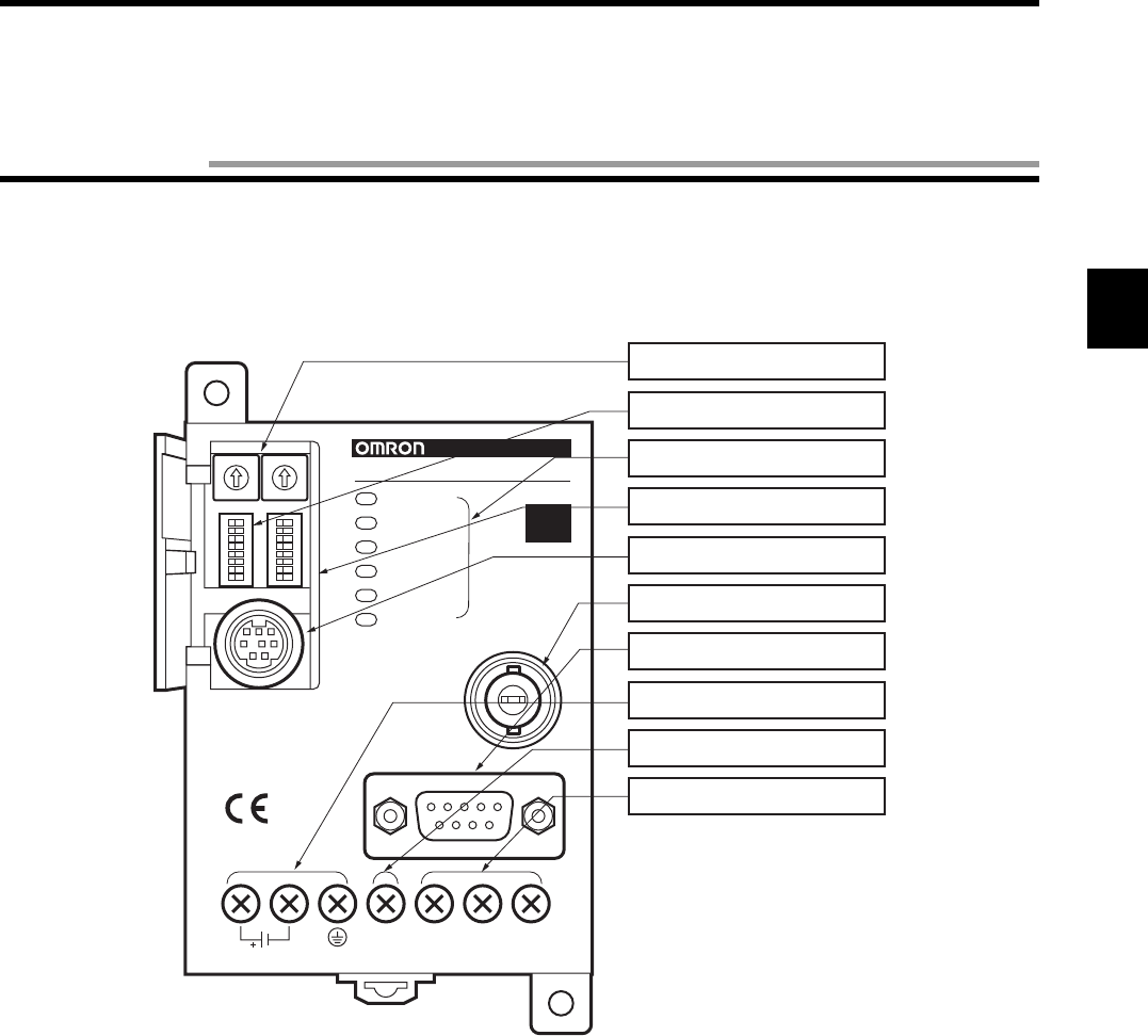
2-1
2-1-1 Component Names and Functions
•Model V670-CD1D-V1
0
1
2
3
4
5
6
7
8
9
0
1
2
3
4
5
6
7
8
9
SW1 SW2
SW3 SW4
RUN
COMM
NORM/ERR
RST/IN
OUT1
OUT2 ANTENNA
RS-232C
O.COMOUT2
GR
RST
/IN
OUT1
MADE IN JAPAN
24VDC
24VDC 7W
V6 7 0 - CD1 D
V670-CD1D-V1
ID
(1)Node number setup switch
(2)Dip switch
(3)LED display
(4)Cover
(5)Connecting port for
programming console
(6)Connecting port for antenna
(7)RS-232C port
(8)Power supply terminals
(9)Reset terminal/Input terminal
(10)Output terminals
Chapter 2 Specifications and Performance
2-1 Controller
2-1 Controller
2-2
No.
Name Function Description
(1) Note number setup switch Sets a controller node
number.
Used to identify the controllers when a maximum of 31
controllers are connected to one host computer.
(2) Dip switch Sets every mode. Sets an input function, operation mode, protocol, com-
munication conditions, etc.
(3) LED display An operation status is shown on this LED displayed.
RUN Green Shows the RUN sta-
tus.
Turns on when an operation is normal.
COMM Green Shows an operation
status.
Turns on during the communication to a tag.
NORM/ERR Green Shows the end of
communication.
Turns on once and turns off when the communication has
ended correctly.
Red Shows an error. Turns on once and turns off when the communication has
ended due to an error. Turns on when a system error
occurs.
RST/IN Green
Shows an input status.
Turns on when the RST/IN input signal turns ON.
OUT1 Green
Shows an output status.
Turns on when the OUT1 output signal turns ON.
OUT2 Green
Shows an output status.
Turns on when the OUT2 output signal turns ON.
(4) Cover
Cover common to (1), (2) and (5).
Open as necessary.
(5) Connecting port for pro-
gramming console
Used to connect a
programming con-
sole.
Our programming console type C200H-PRO27 (unbun-
dled) can connect to this port through the connecting
cable model V700-P10 (unbundled). When you operate
the programming console, use the key sheet that comes
with the V700-P10.
(6) Connecting port for antenna Used to connect an
antenna.
One antenna can connect to this port. To extend the
cable, use model V670-A4(unbundled).
(7) RS-232C port Used to connect a
host device.
Based on the RS-232C, a general-purpose programma-
ble controller (PLC) and PC can connect to this port.
(8) Power supply terminal Terminal for power supply.
24 VDC+ Supplies the power. Connects the "+" side of 24 VDC power supply.
24 VDC- Connects 0 V.
GR Ground Class D (Class III).
(9) Input terminal Terminal for input.
RST/IN Supplies a reset sig-
nal or trigger signal.
When external reset input and external trigger input are
used, they connects to this terminal together with 24
VDC- in pairs. Function can be selected with a dip
switch.
(10)
Output terminal Terminal for output.
OUT1 Output signal 1 When external output is used, it connects to this terminal
together with O.COM in pairs.
OUT2 Output signal 2
O.COM Output common

2-1 Controller
2-3
2-1-2 General Specifications
2-1-3 Performance Specifications
Item Specifications
Model V670-CD1D-V1
Power supply voltage
(Power consumption)
24 VDC±10%
(7 W or less)
Ambient operating temperature
0 to +55°C (no icing)
Ambient operating humidity
35 to 85%RH (no condensation)
Ambient storage temperature
-20 to +75°C (no icing)
Ambient storage humidity 35 to 85%RH (no condensation)
Insulation resistance 20 MΩ or more (at 100 VDC mega) (1) to (6).
(1) Between a group of the power supply terminals and the grounding terminal.
(2) Between a group of the power supply terminals and a group of the output terminals.
(3) Between a group of the power supply terminals and the case.
(4) Between a group of the output terminals and the grounding terminal.
(5) Between a group of the output terminals and the case.
(6) Between the grounding terminal and the case.
Withstand voltage Leakage current 20 mA or less at 1,000 VAC (for 1 minute).
Impressed to (1) to (6) above.
Protective structure Contains a panel.
Vibration resistance 10 to 150 Hz, double amplitude 0.2 mm, acceleration 15 m/s2.
Performing sweep 10 times for 8 minutes in an upward, downward, leftward, rightward, forward and backward directions.
Impact Giving impact of 150 m/s2 3 times each in upward, downward, leftward, rightward, forward
and backward directions, i.e., 18 times in total.
Ground According to Class D (conventional Class III)
Material PC/ASA resin
Weight Approximately 270 g
Installation DIN or M4 screws
Item Specifications
Communication
function
Single/Repeat/Input mode access function.
Write protect function/Memory check function
Self-Execution Function
Maintenance
function
Error reading function
Diagnosis func-
tion
CPU error, host communication error, satellite communication error.
I/O function Input contact: 1 (RST/IN)
Output contact: 2 (OUT1 and OUT2)
2-1 Controller
2-4
2-1-4 Communication Specifications
* This can be set by a dip switch of the controller. For how to set, refer to Chapter 3.
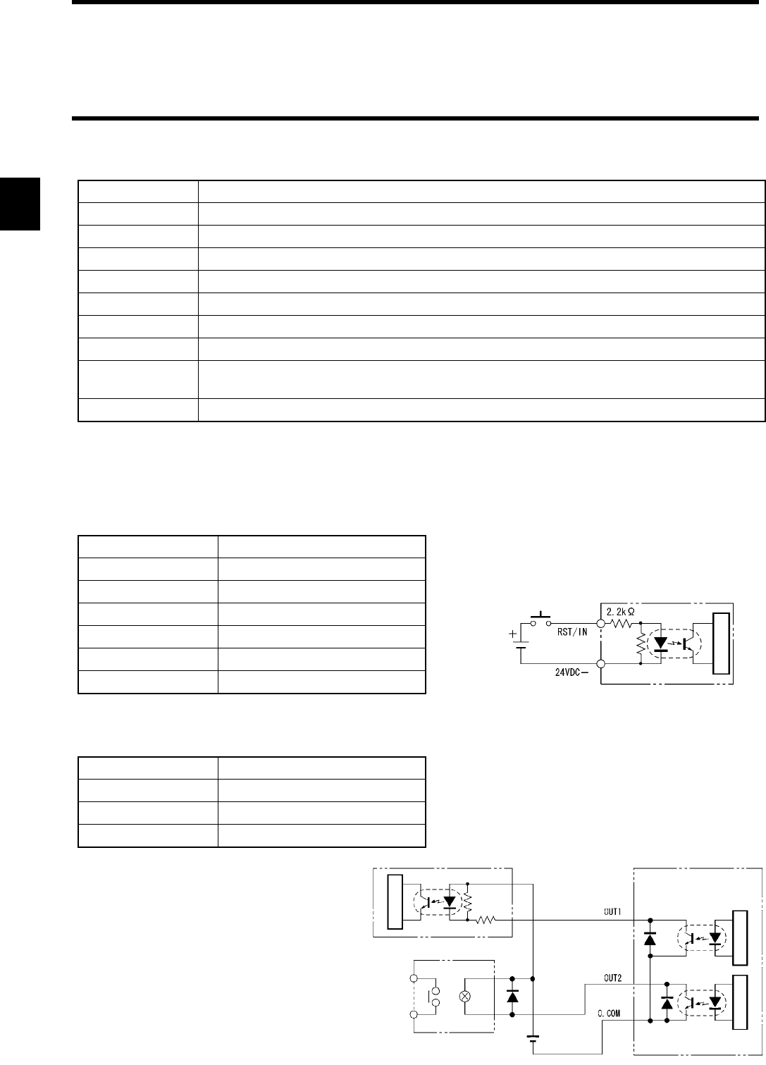
2-1-5 I/O Specifications
•Input Specifications (RST/IN)
•Output Specifications (OUT1/OUT2)
The output is the open collector specification.
Item Specifications
Base specification RS-232C
Communication method
EIA/TIA-232-E
Transmission rate 9600 bps, 19200 bps, 38400 bps, 115200 bps *
Synchronization method
Start-stop synchronization (Stop bit 1 or 2) *
Transmission code
ASCII7 unit or JIS8 unit *
Error control Vertical parity (even, odd, nil)*. Horizontal parity is used as FCS.
Line length A maximum of 15 m.
Suitable connector
D-SUB 9-pin, male
Model XM2A-0901 (plug) and model XM2S-0911 (hood), which come with our controller.
Recommendable cable
CO-MA-VV-SB 5Px28AWG (Hitachi Cable)
Item Specifications
Input voltage 24 VDC ±10% (including ripple)
Input impedance 2.2 kΩ
Input current 10 mA TYP (24 VDC)
ON voltage 19 to 24 V
OFF voltage 5 V or less
Input response time 40 µs or less
Item Specifications
Maximum open/close ability
24 V ±10% 100 mA
Leakage current 1 µA or less
Residual voltage 1.0 V or less
Internal
24VDC
Circuit Structure
Controller input section
Circuit Structure
Input circuit Controller output section
Relay
Internal
InternalInternal
24VDC
2-1 Controller
2-5
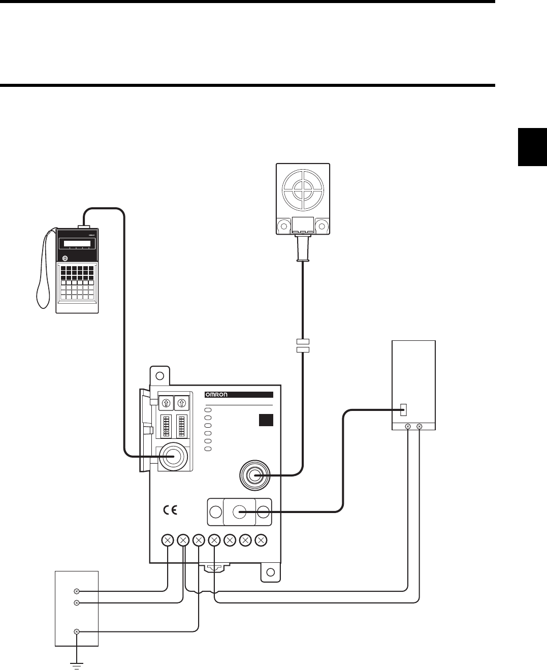
2-1-6 Example of Wiring
0
1
2
3
4
5
6
7
8
9
0
1
2
3
4
5
6
7
8
9
SW1 SW2
SW3 SW4
ANTENNA
RS-232C
COMRST
GR
+ SYNC –
MADE IN JAPAN
24VDC
PRO27
COM24VDC+
24VDC-
GR
RS-232C
RESET
RUN
COMM
NORM/ERR
RST/IN
OUT1
OUT2
V670-CD1D-V1
ID
Connecting Cable
Model V700-P10
Controller
Model V670-CD1D-V1
Antenna Type
Model V670-H11
Host Programmable
Controller (PLC)
Antenna Cable
Model V670-A4
(Only when extension
cable is used)
Programming Console
Model C200H-PRO27
24 VDC Power Supply
2-1 Controller
2-6
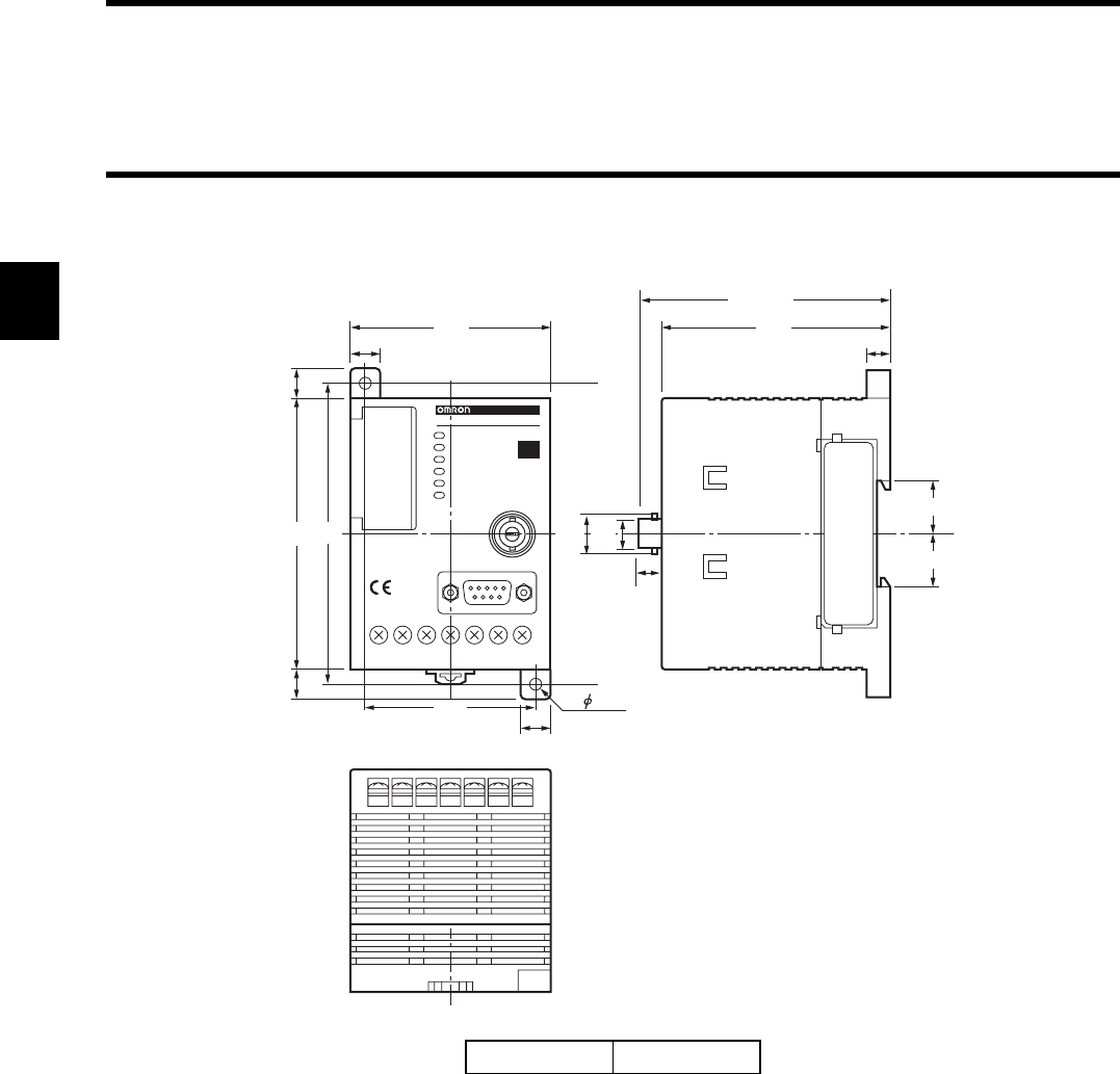
2-1-7 Outside Dimension
Case material PC/ASA resin
10 8
10
10
10
5.5
100
66
56
75
Max. 85
17.5
18
90
2- 4.5
11.5 9.5
V6 7 0 - CD1 D
V670-CD1D-V1
ID
(Unit: mm)

2-7
2-2-1 Specifications
*1: Connectors are not waterproof.
*2: Teflon is the registered trade name of fluorocarbon resin made by DuPont Company and Mitsui DuPont Fluorochemical
Co., Ltd.
Item Specifications
Model V670-H11 V670-H51 V670-H51Q
Oscillating frequency 13.56 MHz
Ambient operating temperature
-10 to +70°C
Ambient operating humidity
35 to 85%RH 35 to 95%RH
Ambient storage temperature
-25 to +85°C -25 to +75°C
Ambient storage humidity
35 to 85%RH 35 to 95%RH
Insulation resistance 20 MΩ or more (at 1,000 VDC mega).
Impressed between a group of terminals and a case.
Withstand voltage 1,000 VAC (for 1 minute).
Impressed between a group of terminals and a case. Leakage current 1 mA or less.
Protective structure IP67 (IEC60529 Standard) *1
IP67 (IEC60529 Standard) *1
IP67g (for communication
side only, JEM Standard)
Vibration resistance
10 to 150 Hz, double amplitude
0.7 mm, acceleration 50 m/s
2
.
Performing sweep 10 times for
8 minutes in an upward, down-
ward, leftward, rightward, for-
ward and backward directions.
10 to 500 Hz, double amplitude 1.5 mm, acceleration 100 m/s
2
.
Performing sweep 10 times for 11 minutes in an upward, down-
ward, leftward, rightward, forward and backward directions.
Impact Giving impact of 150 m/s2 3
times each in upward, down-
ward, leftward, rightward,
forward and backward direc-
tions, i.e., 18 times in total.
Giving impact of 300 m/s2 3 times each in upward, down-
ward, leftward, rightward, forward and backward directions,
i.e., 18 times in total.
Material ABS/epoxy filler
(Cable section material is PVC.)
PBT/brass/filled with epoxy
resin
Teflon*2/filled with epoxy
resin
Cable length 2 m
Weight Approximately 160 g Approximately 140 g Approximately 130 g
2-2 Antenna
2-2 Antenna
2-8
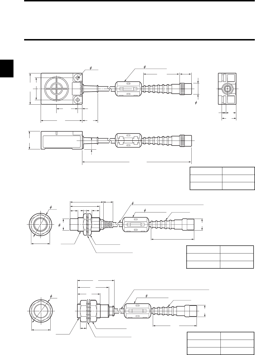
2-2-2 Outside Dimension
•Model V670-H11
•Model V670-H51
•Model V670-H51Q
Case material ABS resin
Filler resin Epoxy resin
Cable PVC
44.9
2- 4.5 Core 18
× 34 mm
15.4
15
11
23
40
20
6
53
2000
27
18
513
28
±
0.1
+70
-0
(Unit: mm)
29
14.8
10
38
43 12
5.0 coaxial cable with a standard length of 2 m
Connector
60.3
15
410
M18 × 1 2-stuffing nut
Toothed lock washer
24
Core 18 × 34 mm
(Unit: mm)
Case material Brass/PBT
Filler resin Epoxy resin
Cable PVC
Toothed lock washer
2-stuffing nut
29
47
40
29
8
M18 × 1
24
5.0 coaxial cable with a standard length of 2 m
Connector
60.3
15
Core 18 × 34 mm
(Unit: mm)
Case material Teflon
Filler resin Epoxy resin
Cable PVC
2-9
2-3-1 Specifications
* Number of accesses is the total number of read/write communication times.
Item Specifications
Model V670-D13F01 V670-D13F01H V670-D13F03
Memory capacity 128 bytes
Type of memory FeRAM (Ferroelectric RAM)
Memory life Number of accesses*: One billion
Data-holding period 10 years after accessing (read or write).
Ambient operating temperature
-10 to +70°C
Ambient storage temperature
-10 to +70°C
Ambient operating humidity
35 to 95%RH 35 to 85%RH
Protective structure IP67 (IEC60529 Standard)
Vibration 10 to 2000 Hz, double amplitude 1.5 mm, acceleration 150 m/s2.
Performing sweep 10 times for 15 minutes in an upward, downward, leftward, rightward, for-
ward and backward directions.
Impact Giving impact of 500m/s2 3 times each in upward, downward, leftward, rightward, forward and
backward directions, i.e., 18 times in total.
Material PPS/epoxy filler resin ABS/epoxy filler resin
Weight Approximately 1 g Approximately 1 g Approximately 6 g
2-3 Tag
2-3 Tag
2-10
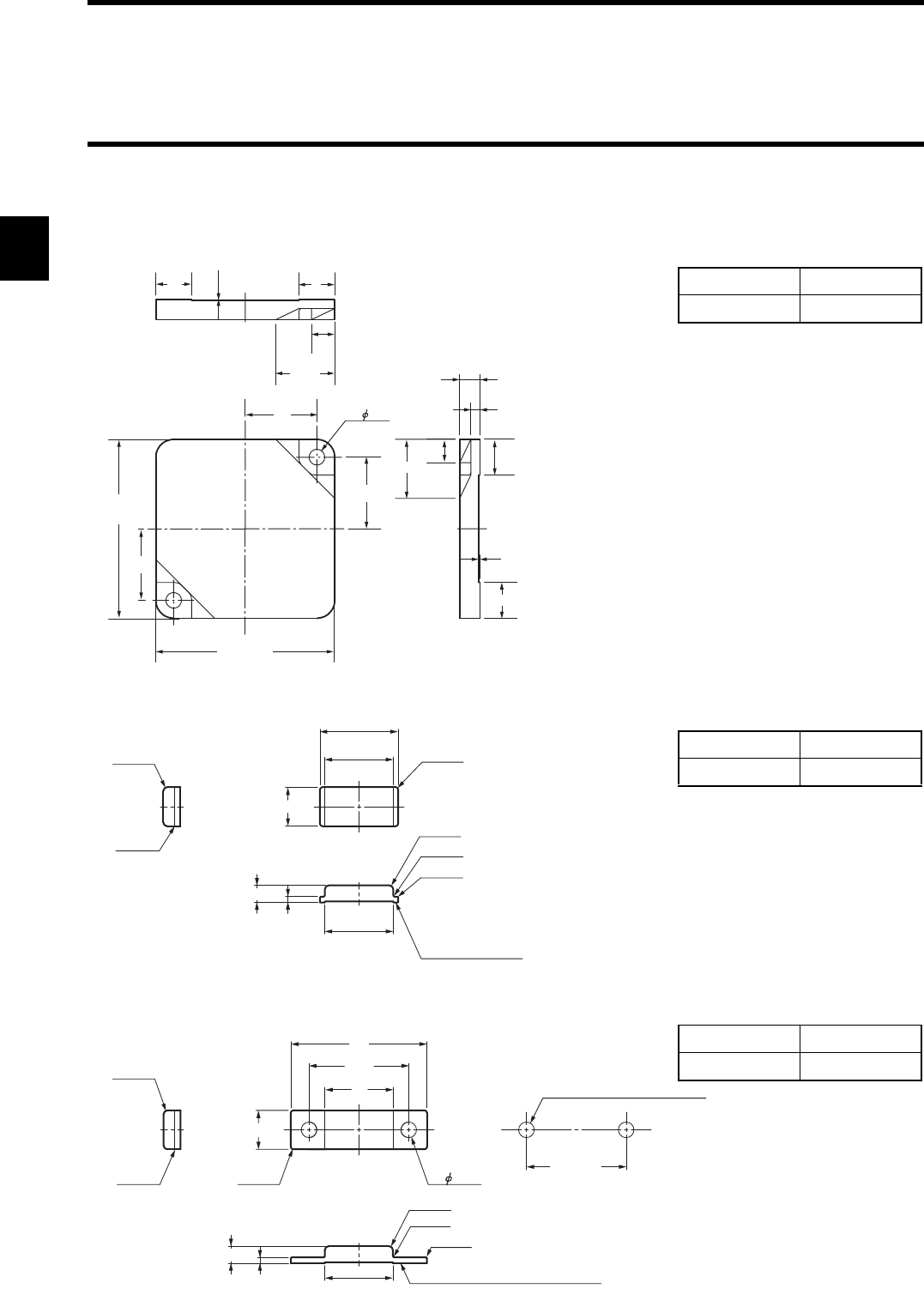
2-3-2 Outside Dimension
•Model V670-D13F03
•Model V670-D13F01
•Model V670-D13F01H
16 2- 3.5
16
40+ 0.1
- 0.5
16
40+ 0.1
- 0.5
16
5.2
8
13.2
0.2
8
13.2
4.5
2
0.2
5.2 8
Case material ABS resin
Filler resin Epoxy resin
(Unit: mm)
Reference plane
for installation
8
3.5
1.2 14
2-R0.8
2-R0.2
2-R0.2
14
16
4-R0.5
2-R0.8
2-R0.2
Case material PPS resin
Filler resin Epoxy resin
(Unit: mm)
2-R0.8
2-R0.2
8
14
20.5
28
4-R0.5
2-R0.8
2-R0.2
2-R0.2
3.5
1.2 14
2- 3.2 20.5 ±
.1
Reference hole for installation
2-φ3.2 hole for M3 screw
Reference plane for installation
Fitting hole dimension
Case material PPS resin
Filler resin Epoxy resin
(Unit: mm)

2-3 Tag
2-11
2-3-3 Memory Map
There are a user area and ID code in memory in a tag. Memory capacity of user area is 128 bytes. You can write 1 byte of data into one
address. Memory area is divided into 4 bytes of pages and every page has its own address like 0000h to 0003h, 0004h to 0007, etc.
♦Memory Map
* When a protect function is used, the addresses 0000h to 0003h are used as protect address information and cannot be used as a user
area. For details, refer to "4-6 Write Protection Function".
♦ID Code
This is a 4-byte area where tag identification number (inherent tag number) is written. The ID code is written at shipment from a fac-
tory and it cannot be modified. The ID code can be read by an ID read command.
Page User Address User Area
When a protect function is not used When a protect function is used
1
$0000
User Area
Specified address in a protect area
$0001
$0002
$0003
.
.
.
.
$0004
User Area
.
.
.
.
$007F
2-3 Tag
2-12
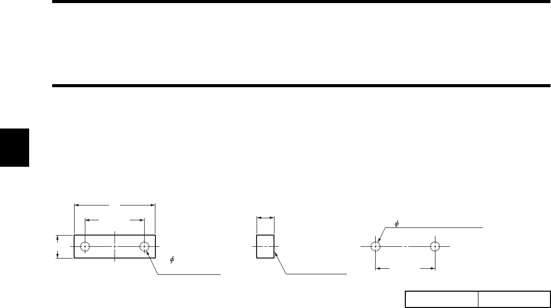
2-3-4 Attachment (Model V670-A81) for Model V670-D13F01H Tag
When a tag is attached to a metal structure, the metal will reduce the communication range of the tag. Model V670-A81 is an attachment
specially designed for Model V670-D13F01H Tag. When combined with this attachment, Model V670-D13F01H tag retains its original
communication range even when installed on a metal structure.
Tag to be combined: Model V670-D13F01H
♦Outside Dimension
♦How to install
Place the attachment on the reference plane of the tag and adjust its position until the fitting holes align with each other. Then secure
both parts with M3 screws.
Screw tightening torque: 5 N • m
♦For general applications
Conform to the tag specifications.
♦Influence of back metal
Use of this attachment increases the distance between the tag and metal surface to 6 mm. Before use, refer to Chapter 9-4, "Influence
of Back Metal of Tag."
Material PPS resin
20.5 ± 0.1
2- 3.2 hole for
M3 screw
8
6
Reference plane
for installation
28
20.5 ± 0.1
Reference hole for installation
Fitting hole dimension
2- 3.2 hole for M3 screw
2-13
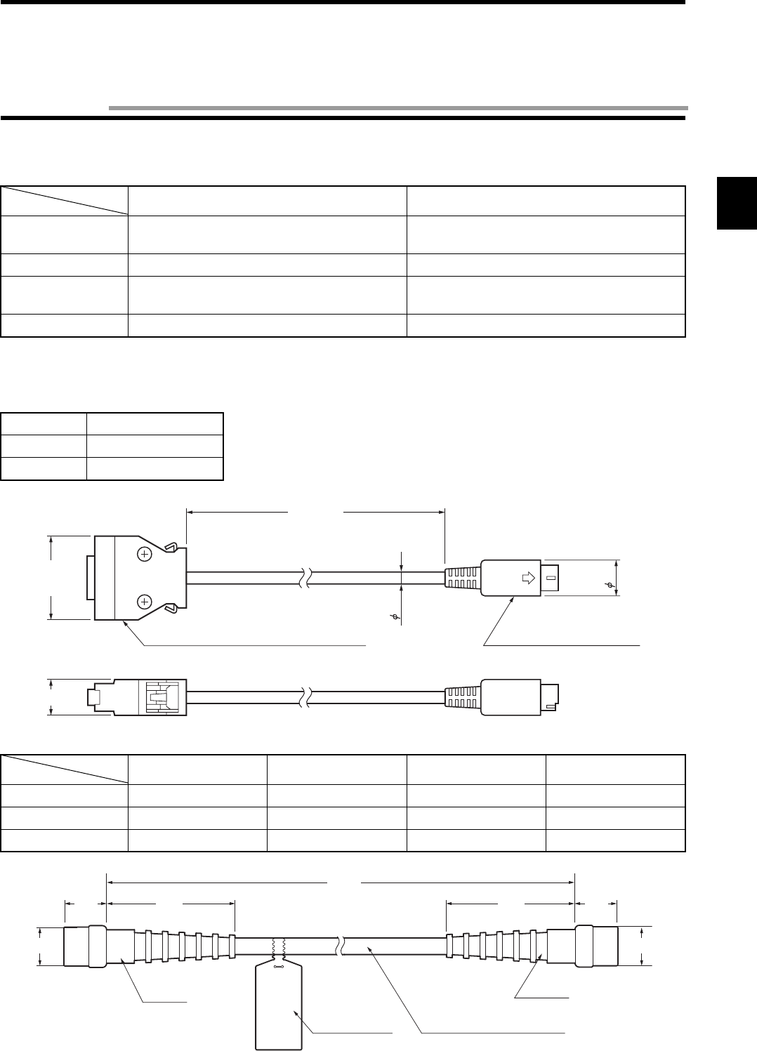
2-4-1 Specifications
2-4-2 Outside Dimension
•Model V700-P10 (Programming console connecting cable)
•Model V670-A4 (Antenna extension cable)
Model V700-P10 Model V670-A4
Insulation resis-
tance
50 MΩ or more between a terminal and
sheathing (at 250 VDC mega).
20 MΩ or more between a terminal and
sheathing (at 1000 VDC mega).
Withstand voltage 250 VAC, 1 minute. 1000 VAC, 1 minute.
Maximum operating
temperature
70°C70°C
Remarks Connector without waterproof specification. Connector without waterproof specification.
Item Model V700-P10
Length Approximately 2 m
Weight Approximately 110 g
Model V670-A40 Model V670-A41 Model V670-A42 Model V670-A43
Length Approximately 3 m Approximately 10 m Approximately 18 m Approximately 28 m
Weight Approximately 140 g Approximately 410 g Approximately 710 g Approximately 1100 g
L1 3000 mm 10000 mm 18000 mm 28000 mm
Model
Item
12
4.8
2000±
100
28.95
Connector (at a programming console side) Connector (at a controller)
12
(Unit: mm)
Model
Item
44.9
L1
44.9
Connector
Connection label Coaxial cable 5 mm in diameter
Connector
15
15
15.4 15.4
+50
-0
(Unit: mm)
2-4 Cable
2-14
Communication range varies depending on the installation conditions and environment conditions. Check the conditions mentioned in
this manual carefully.
♦Maximum communication range
Measurement conditions:
•Combination of Model V670-H11 with Model V670-D13F03
*Antenna extension cable (Model V670-A4: not used)
•Combination of Model V670-H51/H51Q with Model V670-D13F01/D13F01H
*Antenna extension cable (Model V670-A4: not used)
♦Use of extension cable (Model V670-A4)
Use of an extension cable will reduce the communication range.
* For extension cable connection procedure, refer to the descriptions on pages 3-9 and the instruction manual packaged together with
the extension cable.
Antenna / Controller ID Tag Communication Range
Model V670-H11
+ Model V670-CD1D-V1
Model V670-D13F03 5 to 23 mm
(Area width 20 mm or more if the range between a tag
and antenna is 5 to 20 mm.)
Model V670-H51
+ Model V670-CD1D-V1
Model V670-D13F01 /
Model V670-D13F01H
0.5 to 5.0 mm
Model V670-H51Q
+ Model V670-CD1D-V1
Model V670-D13F01 /
Model V670-D13F01H
0.5 to 4.5 mm
Extension cable Communication range
Model V670-H11 Model V670-H51 Model V670-H51Q
Model V670-A40 (3 m) 5.0 to 21.5 mm 0.5 to 5.0 mm 0.5 to 4.5 mm
Model V670-A41 (10 m) 5.0 to 21.0 mm 0.5 to 5.0 mm 0.5 to 4.5 mm
Model V670-A42 (18 m) 5.0 to 20.5 mm 0.5 to 4.0 mm 0.5 to 3.5 mm
Model V670-A43 (28 m) 5.0 to 20.0 mm 0.5 to 4.0 mm 0.5 to 3.5 mm
Antenna
Nonmetal Nonmetal
Tag
Communication
range
Antenna
Nonmetal
Tag
Communication
range
2-5 Communication Range Specifications
2-5 Communication Range Specifications
2-15
2-5-1 Communication Area (Reference)
♦Combination of Model V670-H11 with Model V670-D13F03
The communication area varies depending on the installation conditions and grounding environment.
The operation area formed on a plane, which is on an antenna center line and vertical to the antenna, is shown below.
*Antenna extension cable (Model V670-A4: not used)
♦Combination of Model V670-H51 with Model V670-D13F01/ D13F01H
The communication area varies depending on the installation conditions and grounding environment.
The operation area formed on a plane, which is on an antenna center line and vertical to the antenna, is shown below.
•When tag is attached perpendicular to the passing direction (X-direction) (typical example)
*Antenna extension cable (Model V670-A4: not used)
•When tag is attached horizontally in relation to the passing direction (X-direction) (typical example)
*Antenna extension cable (Model V670-A4: not used)
5
10
15
20
25
30
-40 -30 -20 -10 0 10 20 30 40
Communication area characteristic
Y
X
Unit: mm
Model V670-H11
Y (mm)
X (mm)
Nonmetal
Nonmetal
Model V670-D13F03
0-15 -10 -5 5 10 15
1
2
3
4
5
6
7
8
9
X
Y
Communication area characteristic
Unit: mm
Model V670-H51
Y (mm)
X (mm)
Nonmetal
Model V670-D13F01 (H)
0-15 -10 -5 5 10 15
1
2
3
4
5
6
7
8
9
X
Y
Communication area characteristic
Unit: mm
Model V670-H51
Y (mm)
X (mm)
Nonmetal
Model V670-D13F01 (H)
2-5 Communication Range Specifications
2-16
♦Combination of Model V670-H51Q with Model V670-D13F01/ D13F01H
The communication area varies depending on the installation conditions and grounding environment.
The operation area formed on a plane, which is on an antenna center line and vertical to the antenna, is shown below.
•When tag is attached perpendicular to the passing direction (X-direction) (typical example)
*Antenna extension cable (Model V670-A4: not used)
•When tag is attached horizontally in relation to the passing direction (X-direction) (typical example)
*Antenna extension cable (Model V670-A4: not used)
0-15 -10 -5 5 10 15
1
2
3
4
5
6
7
8
9
X
Y
Communication area characteristic
Unit: mm
Model V670-H51Q
Y (mm)
X (mm)
Nonmetal
Model V670-D13F01 (H)
0-15 -10 -5 5 10 15
1
2
3
4
5
6
7
8
9
X
Y
Communication area characteristic
Unit: mm
Model V670-H51Q
Y (mm)
Nonmetal
X (mm)
Model V670-D13F01 (H)
2-5 Communication Range Specifications
2-17
2-5-2 Operation Time (Reference)
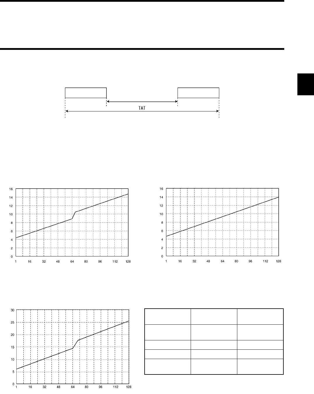
There are TAT (Turn Around Time) and communication time in the operation time.
TAT means the total processing time required to operate V670 from the viewpoint of a host device. The communication time means a
time required for the communication between an antenna and tag, excluding host communication.
♦Communication time
Time required for the communication between an antenna and ID tag. The time varies depending on data amount to be read and written.
The communication time can be calculated from the charts and formulas below.
•Read • Write
•Write (with verification)
Command Response
Communication time
Number of processed bytes (Byte)
Communication time (ms)
Number of processed bytes (Byte)
Communication time (ms)
Number of processed bytes (Byte)
Communication time (ms)
Command Bytes Communication
time (ms)
Read 1 to 64 bytes
65 to 128 bytes
0.07 x N + 4.22
0.07 x N + 5.64
ID Read 4 bytes 1.59
Write 1 to 128 bytes 0.07 x N + 4.72
Write
(with verification)
1 to 64 bytes
65 to 128 bytes
0.14 x N + 6.45
0.14 x N + 7.79
N: Number of bytes to be processed

2-5 Communication Range Specifications
2-18
In the communication with a tag, any data is read and written at every 4 bytes. Therefore, to minimize the communication time, specify
the address and the number of bytes suitably so that the address for writing can be a multiple of 4.
Example: If 4 bytes of data is written from the address 0001h, change the address to 0000h.
If you cannot change as stated above due to the structure of change system, add the following time to the communication time.
♦TAT
Time from the start of command transmission by a host device to the end of receiving of response to the host device. It can be calculated
from the communication time and the number of characters of command/response. The formula is as follows:
TAT = command transfer time + communication time + response transmission time
* The number of bits per character and baud rate vary depending on the communication conditions (baud rate, data length, parity and
stop bit).
Assuming that the number of characters of command is A, the number of characters of response is B, the baud rate is 9600 bps, data
length is 7 bits, parity is even and stop bit is 2 bits, the following formula can be obtained:
When a protect function is used +2.9 ms
When a start address is not a multiple of 4 +2.9 ms
When an end address (start address + the number of addresses) is not a multiple of 4 +2.9 ms
Correct Usage
The formula above calculates the time when processing (transmission of command) starts if the ID tag is within an area
of communication with an antenna. The time varies depending on a communication mode and ID tag status.
Bits per character (bit)
Baud rate (bps)
Transmission time = × number of characters (second)
11 × (A + B)
9600
TAT = + communication time (second)
2-5 Communication Range Specifications
2-19
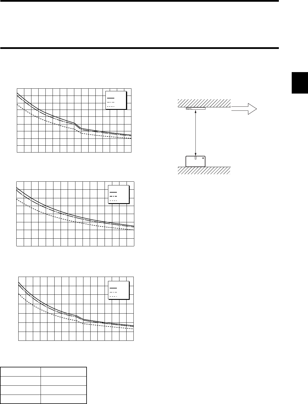
2-5-3 Traffic and Passing Speed (Reference)
♦Combination of Model V670-H11 with Model V670-D13F03
•Read
•Write (without verification)
•Write (with verification)
•ID Read
Distance Passing speed
10 mm 750 m/min
15 mm 710 m/min
20 mm 600 m/min
1 163248648096112128
Number of processed bytes (Byte)
450
400
350
300
250
200
150
100
50
0
Maximum passing speed (m/min)
10mm
Distance
15mm
20mm
Antenna
Distance (mm)
Passing speed (m/min)
Nonmetal
Nonmetal
Tag
Measurement Conditions:
*Antenna extension cable (Model V670-A4: not used)
0
500
100
150
200
250
300
350
400
1 163248648096112128
Number of processed bytes (Byte)
Maximum passing speed (m/min)
10mm
Distance
15mm
20mm
0
50
100
150
200
250
300
350
1 163248648096112128
Number of processed bytes (Byte)
Maximum passing speed (m/min)
10mm
Distance
15mm
20mm
* Passing speed varies depending on the distance Y
(between tag and antenna), axial displacement, etc.
Refer to the data on communication area to use the
product over its widest communication range.
* Graphs are for reference only. Prior to practical applica-
tion, carry out the evaluation test of the product.
* Graphs do not include communication error correction.
2-5 Communication Range Specifications
2-20
♦Combination of Model V670-H51/H51Q with Model V670-D13F01/D13F01H
•Vertical
•Read
•Write (without verification)
•Write (with verification)
•ID Read
Distance Passing speed
3 mm 225 m/min
1 163248648096112128
Number of processed bytes (Byte)
200
160
180
140
120
100
80
60
40
20
0
Maximum passing speed (m/min)
3mm
Distance
Passing speed (m/min)
A
ntenna
Distance (mm)
Tag
Nonmetal
Measurement Conditions:
*Antenna extension cable (Model V670-A4: not used)
1 163248648096112128
Number of processed bytes (Byte)
200
160
180
140
120
100
80
60
40
20
0
Maximum passing speed (m/min)
3mm
Distance
1 163248648096112128
Number of processed bytes (Byte)
100
80
90
70
60
50
40
30
20
10
0
Maximum passing speed (m/min)
3mm
Distance
* Passing speed varies depending on the distance Y
(between tag and antenna), axial displacement, etc.
Refer to the data on communication area to use the
product over its widest communication range.
* Graphs are for reference only. Prior to practical applica-
tion, carry out the evaluation test of the product.
* Graphs do not include communication error correction.
2-5 Communication Range Specifications
2-21
♦Horizontal
•Read
•Write (without verification)
•Write (with verification)
•ID Read
Distance Passing speed
3 mm 275 m/min
1 163248648096112128
Number of processed bytes (Byte)
200
160
180
140
120
100
80
60
40
20
0
Maximum passing speed (m/min)
3mm
Distance
Antenna
Distance (mm)
Tag
Passing speed (m/min)
Nonmetal
Measurement Conditions:
*Antenna extension cable (Model V670-A4: not used)
1 163248648096112128
Number of processed bytes (Byte)
200
160
180
140
120
100
80
60
40
20
0
Maximum passing speed (m/min)
3mm
Distance
1 163248648096112128
Number of processed bytes (Byte)
120
80
100
60
40
20
0
Maximum passing speed (m/min)
3mm
Distance
* Passing speed varies depending on the distance Y
(between tag and antenna), axial displacement, etc.
Refer to the data on communication area to use the
product over its widest communication range.
* Graphs are for reference only. Prior to practical applica-
tion, carry out the evaluation test of the product.
* Graphs do not include communication error correction.

2-22
3-1
3-1-1 Switch Setting
To set the switches, open a cover at the upper left part of the unit.
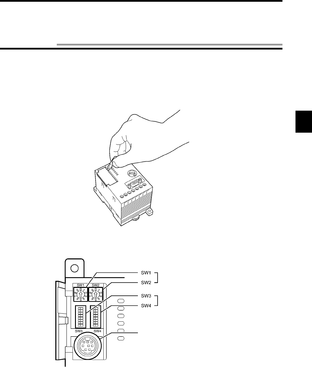
3-1-1-1 How to Open Cover
To open the cover, insert a screwdriver, which comes with the controller, into a notch at the left end of the cover.
When the cover opens, you can see the two node number setup switches (SW1 and SW2), two dip switches (SW3 and SW4) and con-
necting port for programming console.
Node number setup switch
Dip switch
Connecting port for programming
console
Chapter 3 Setting and Installation
3-1 Controller
3-1 Controller
3-2
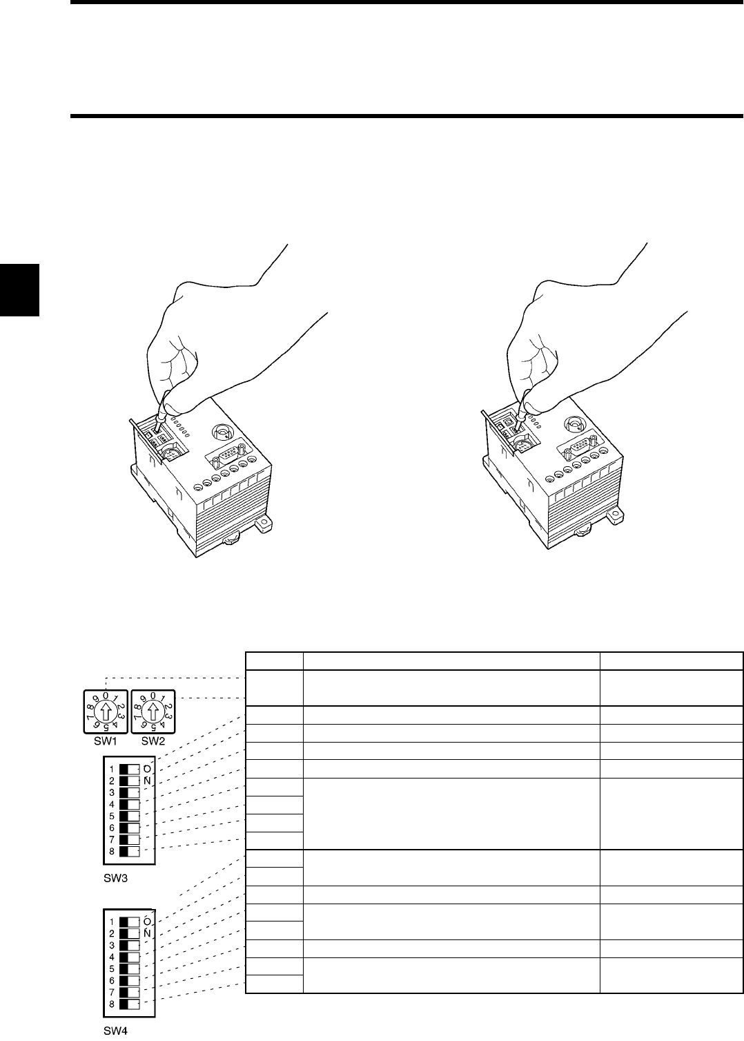
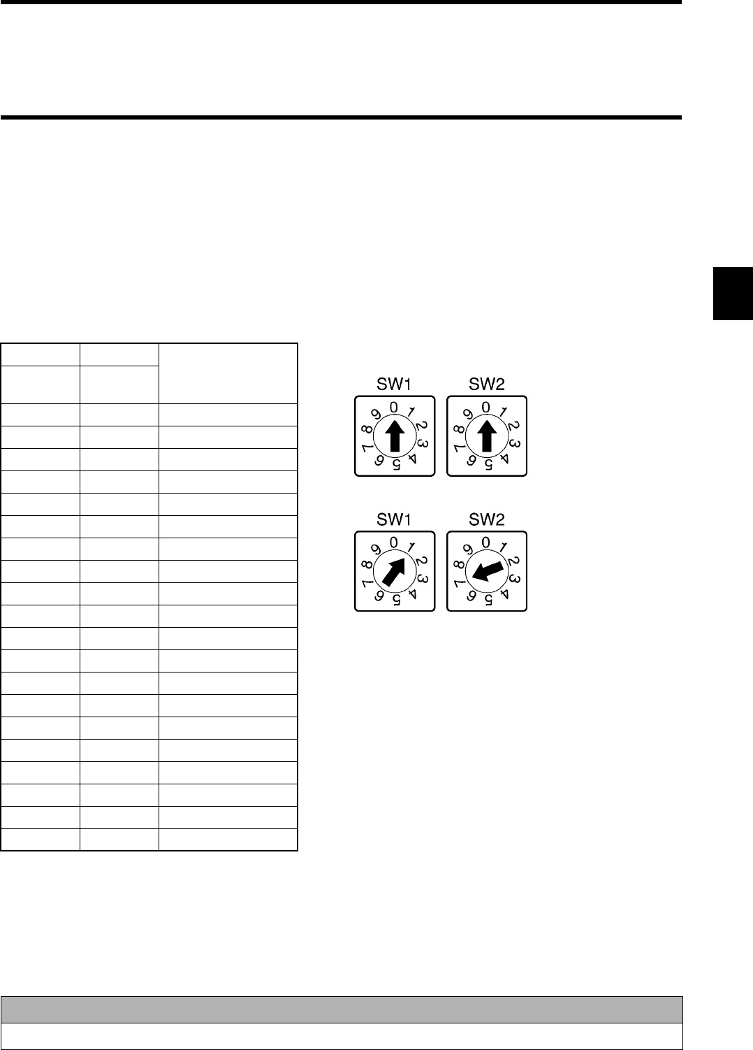
3-1-1-2 How to Set
Set the switch using the screwdriver which comes with the controller as shown below.
•Setting a node number
Turn clockwise or counterclockwise.
3-1-1-3 Setting List
Set the switches according to the list below. (The switches are set to a default value at shipment from a factory.)
Name Function Default Value
SW1 Node number setup switch used in 1:N protocol. 00
SW2
SW3-1
Switch to change a function of input terminal (RST/IN).
Reset input
SW3-2 Switch to set an operation mode at startup.
Command execution mode
SW3-3 Switch to enable or disable verification at writing. Disabling verification
SW3-4 Switch to set a protocol (1:1 / 1:N). 1:1 protocol
SW3-5 Set to OFF. OFF
SW3-6
SW3-7
SW3-8
SW4-1 Switch to set a communication speed of RS-232C. 9600 bps
SW4-2
SW4-3 Switch to set data length of RS-232C. 7 bits
SW4-4 Switch to set parity of RS-232C. Even parity
SW4-5
SW4-6 Switch to set stop bit of RS-232C. 2 bits
SW4-7 Set to OFF. OFF
SW4-8
•Setting a dip switch
Set to the right or left.
(Left)
(Right)
3-1 Controller
3-3
3-1-1-4 Setting Node Number Setup Switch
♦Node number
To connect several controllers to one host device using a link adapter etc., the host device needs to identify each of those controllers.
The number to identify them is referred to as node number. A unique node number must be assigned to every controller.
The command and response of 1:N protocol have the node number. So, unless the node number is assigned appropriately, any commu-
nication cannot be made.
♦Setting node number
Set the node number with the two node number setup switch. SW1 (left) is for an upper order and SW2 (right) for a lower order. Avail-
able number range is from 00 to 31 as shown below.
The factory default setting of the node number is 00.
SW1 SW2
Node Number
Upper
order
Lower
order
000
011
022
033
044
055
066
077
088
099
1010
1111
:::
2929
3030
3131
3 2 Disabled
3 3 Disabled
:::
9 9 Disabled
Correct Usage
Never assign the numbers 32 to 99 to the node number setup switch.
Node No. 0
Node No. 17
Example of setting:
3-1 Controller
3-4
3-1-1-5 Setting a Dip Switch
♦SW3
SW3-1: Input function change
SW3-2: Operation mode
SW3-3: Verification at writing
SW3-4: Protocol designation
SW3-1 Description
ON Functions as trigger input.
OFF Functions as reset input.
SW3-2 Description
ON Starts in the Self-Execution mode when the power supply turns ON.
OFF Starts in the Command Execution mode when the power supply turns ON.
SW3-3 Description
ON Enables verification.
OFF Disables verification.
SW3-4 Description
ON Uses the 1:N protocol.
OFF Uses the 1:1 protocol.
Correct Usage
Set SW3-5, SW3-6, SW3-7 and SW3-8 to OFF always. Otherwise, any operation cannot be guaranteed.
3-1 Controller
3-5
♦SW4
SW4-1/4-2: Communication speed setting
SW4-3: Data length setting
SW4-4/4-5: Parity bit setting
SW4-6: Stop bit setting
SW4-2 SW4-1 Description
ON ON 115200 bps
OFF 38400 bps
OFF ON 19200 bps
OFF 9600 bps
SW4-3 Description
ON 8 bits
OFF 7 bits
SW4-5 SW4-4 Description
ON ON Even parity
OFF No parity
OFF ON Odd parity
OFF Even parity
SW4-6 Description
ON 1 bit
OFF 2 bits
Correct Usage
Set SW4-7 and SW4-8 to OFF always. Otherwise, any operation cannot be guaranteed.

3-1 Controller
3-6
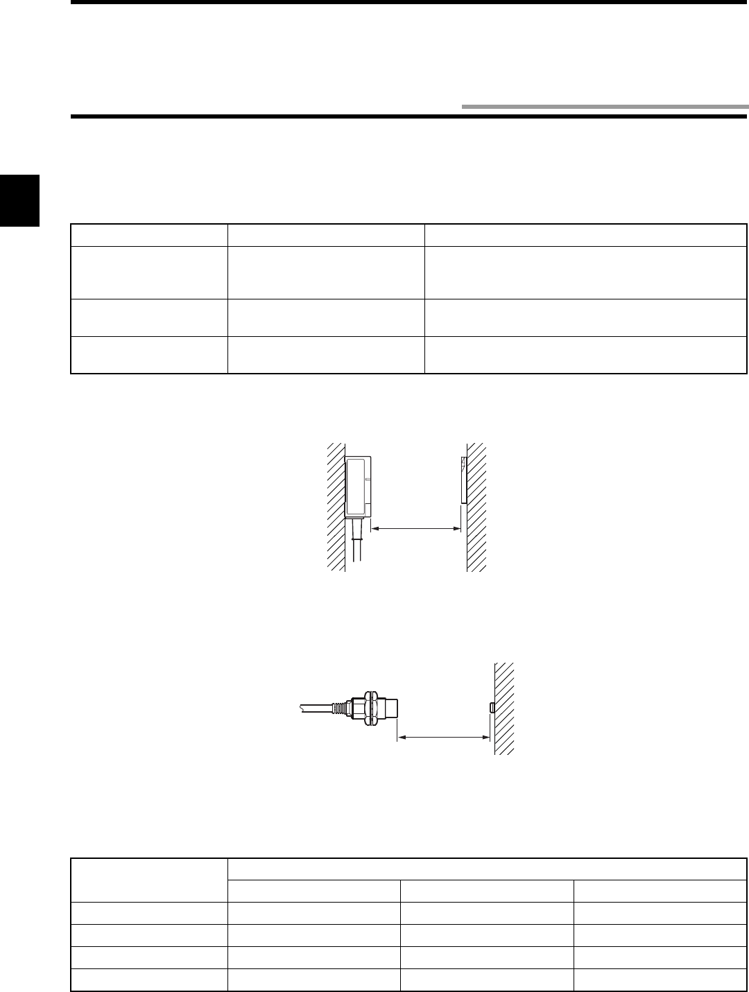
3-1-2 Installation Site
The controller model V670-CD1D-V1 has high reliability as durable control device under any environmental conditions. To increase
the system reliability and to fulfill the functions completely, install the controller according to the instructions below.
♦Installation site
Do not install the controller at any place below:
• Place where the ambient temperature is out of the range between 0 and +55°C, where the temperature fluctuates considerably and
where moisture condensation occurs.
• Place where the relative humidity is out of the range between 35 and 85%RH.
• Place where there is corrosive gas, flammable gas, dust, salt or iron powder.
• Place affected by vibration or impact.
• Place exposed to the direct sunlight.
• Place splashed with water, oil or chemicals
♦Assembly in panel
The ambient operating temperature of controller is between 0 and +55°C. The following conditions must be met.
• Provide sufficient space for ventilation.
• Do not install the controller near by any heating sources (heater, transformer and large-sized resistance).
• If the ambient temperature rises to 55°C or more, install a ventilating fan or air conditioner to keep the temperature at 55°C or less.
• If you wire a power line (for high current to drive a motor) near the controller, test it fully to reduce the influence of noise and wire it
according to the wiring conditions with care.
Note
When you install the controller, be sure to follow the instructions above and test it fully.
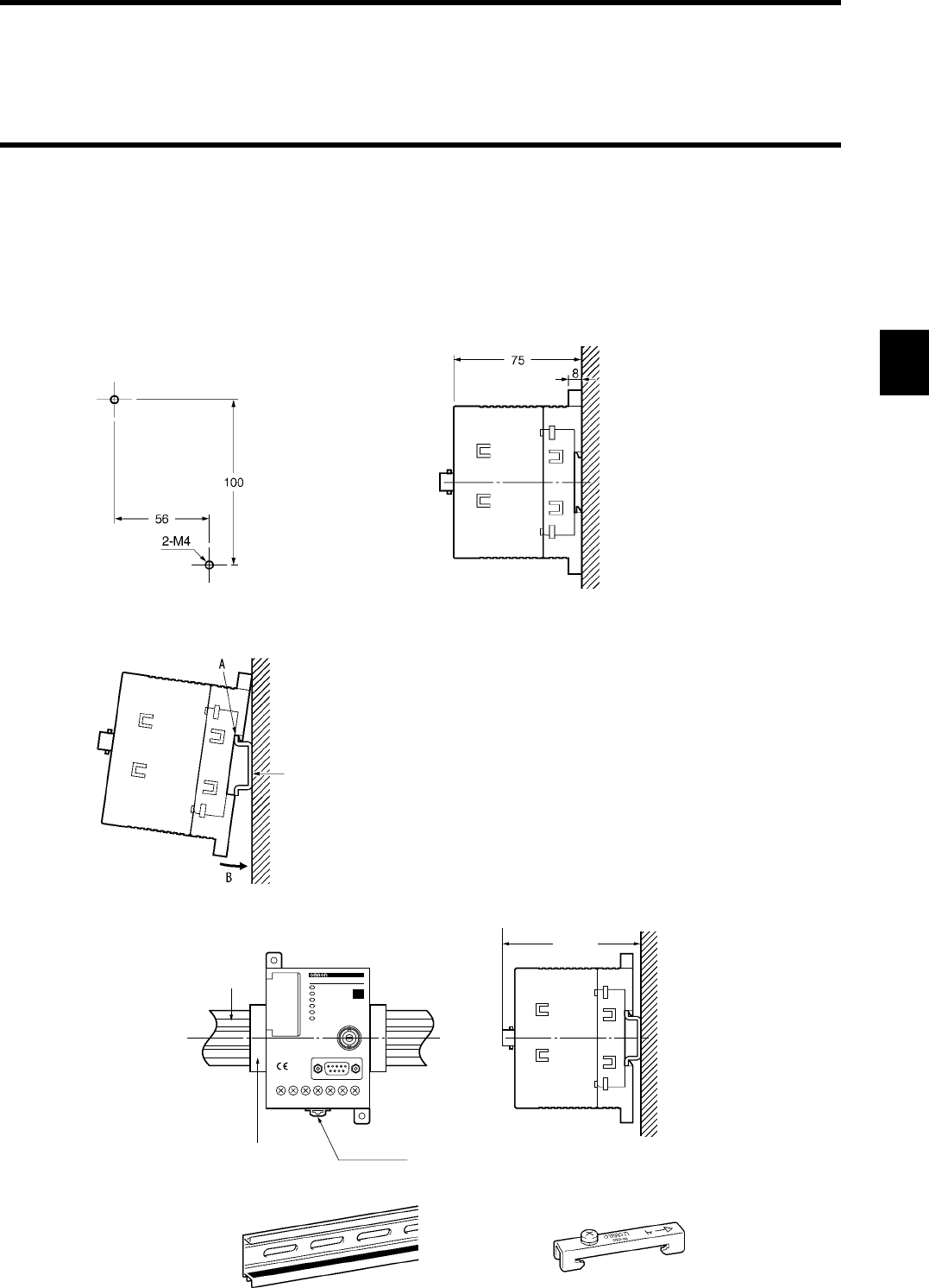
3-1 Controller
3-7
3-1-3 How to Install
The controller can be installed in a panel with screws or on a DIN rail.
♦Installation in a panel
If you install the controller in a panel, be sure to use spring washers, flat washers and M4 screws. (Tightening torque: 1.2 N•m or less)
Do not use any organic solvent such as lock paint to fix screws. Otherwise, the case may crack.
♦Installation on a DIN rail
(Unit: mm)
•When you install the controller on the DIN rail, hook the
controller over the A and push the controller in the direc-
tion B.
•When you remove the controller from the DIN rail, pull
the hook downward and remove the controller pushing
slightly upward.
Recommendable DIN rail
Model PFP-100N2 (Rail
length 1 m)
(OMRON)
MAX.90
DIN Rail
End Plate Hook
V670-CD1D
V670-CD1D
ID
Support Rail
Model PFP-100N2 End Plate
Model PFP-M
(Unit: mm)
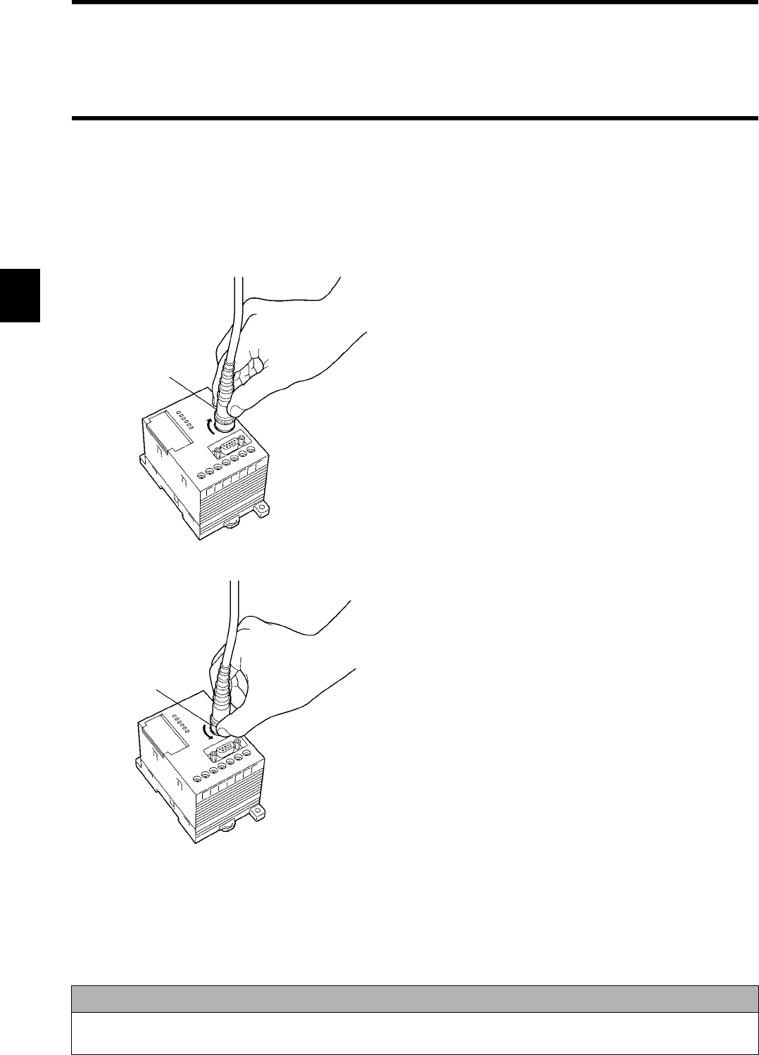
3-1 Controller
3-8
3-1-4 How to Connect Antenna
You can connect one antenna to the controller. The antenna can be extended up to 30 m by using the extension cable model V670-A4
(unbundled). Only one extension cable can be used.
♦How to connect and disconnect a connector
•How to connect
•How to disconnect
Correct Usage
Do not pull the cable forcibly. Otherwise, the cable may be broken or damaged. When you connect or disconnect the
connector, be sure to turn off the power supply. Otherwise, a trouble may occur.
Lock (1) Hold the cable lock of connector and fit a lug of the con-
troller in a groove in the connector lock.
(2) Push the connector straight tightly.
(3) Turn the connector lock clockwise.
Lock
(1) Turn the connector lock counterclockwise.
(2) Hold the lock and pull out it straight.
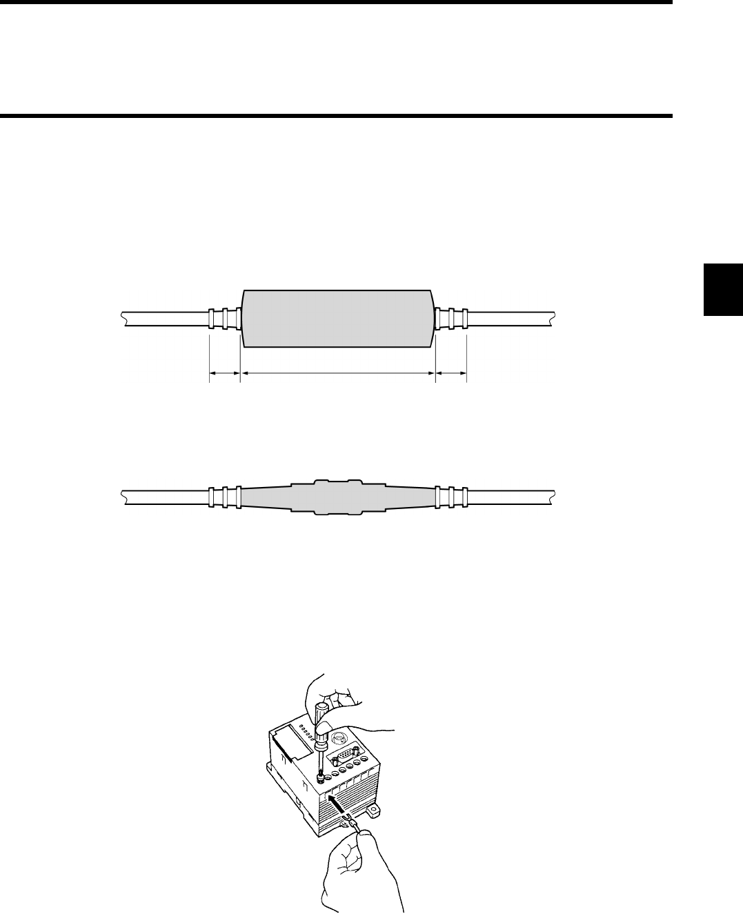
3-1 Controller
3-9
3-1-5 How to Connect Extension Cable and How to Extend Antenna
The antenna can be extended by using the extension cable type V670-A4 (unbundled). The extension cables up to 28 m in length are
available. When you use the extension cable, to prevent the devices being broken due to static electricity, follow the instructions below:
♦Procedure to connect extension cable
Connect the antenna and extension cable with a connector accessory (accessory: WTN-B-384). Cover a metal part of connector joint
with a sheath (Sumitomo Electric Industries: SumiTube A 20 mm in diameter) as shown below.
Heat the sheath (120°C is recommendable) using a drier etc. to shrink it.
* The cable and connector may be deformed if the sheath is heated for a long time. Heat the sheath quickly.
♦Procedure to disconnect extension cable
Remove the tube using a nipper etc. first and then remove the extension cable. If a new tube is required, use the heat shrinkable tube
(SumiTube A 20 mm in diameter) of Sumitomo Electric Industries which should be cut down to 10 cm.
3-1-6 How to Wire
Wire as shown in this figure.
Approximately
15 mm
Approximately
100 mm
Approximately
15 mm
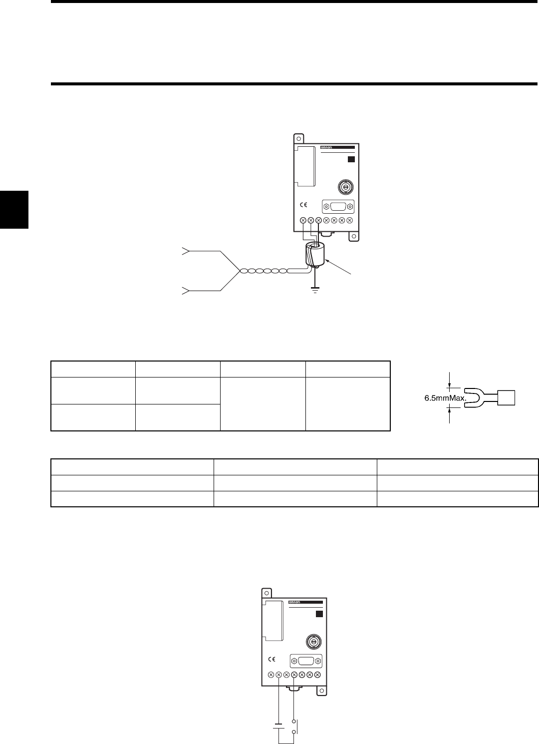
3-1 Controller
3-10
3-1-6-1 Wiring Power Supply and Grounding Cable
M3 self-up screws are used for the power supply and ground terminal. For a crimp terminal, use any of terminals below. Tightening
torque should be approximately 0.6 N•m.
♦Applicable crimp terminal
♦Recommendable DC power supply (small-sized) (OMRON)
* Rated power consumption of the controller is 24VDC and 0.2 A (7 W). Decide the capacity taking into consideration inrush current
(approximately 5 A).
3-1-6-2 Wiring Reset Signal
Manufacturer Model Applicable Wire Type
Japan Solderless
Ter m i n al
1.25-N3A AWG24 to
AWG16
Fork
Japan Solderless
Ter m i n al
1.25-Y3A
Model Output Capacity Input Voltage
S82K-03024 24 VDC 1.3 A 100/200 VAC
S82J-0224 24 VDC 1.1 A 100 VAC
V6 7 0 - CD1 D
V670-CD1D-V1
ID
Grounding of Class D
+DC24V
0V
(Example of Wiring)
Ferrite core
(attached to the product)
24VDC Reset Input
O.COM
OUT2
OUT1RST
/IN
V6 7 0 - CD1 D
V670-CD1D-V1
ID
(For M3)
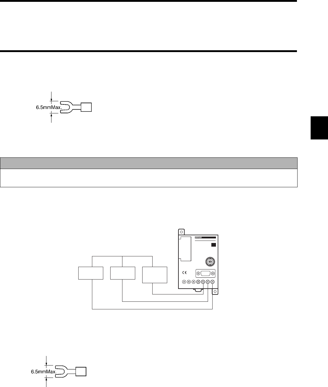
3-1 Controller
3-11
•Crimp terminal for terminal
M3 self-up screws are used for the terminal.
For a crimp terminal, use the terminal below.
Tightening torque should be approximately 0.6 N•m.
3-1-6-3 Wiring Output Signal
•Crimp terminal for terminal
M3 self-up screws are used for the terminal.
For a crimp terminal, use the terminal below.
Tightening torque should be approximately 0.6 N•m.
Correct Usage
Take care that the input voltage does not exceed the maximum impressed voltage (26.4 V). Otherwise, a trouble may
occur in devices.
(For M3)
O.COM
OUT2
OUT1
O.COM
OUT2
OUT1RST
/IN
V6 7 0 - CD1 D
V670-CD1D-V1
ID
DC Power
Supply
Relay External
I/O Unit
+
-
(For M3)
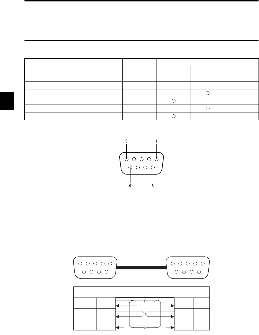
3-1 Controller
3-12
3-1-7 Connecting RS-232C Interface
Note 1: To prevent an operation error, ground the shielded wire either at the controller side or the computer side mentioned above. (The
figure above shows an example of grounding the shielded wire at the ID controller side.)
Note 2: Short-circuit pin No. 7 (RS) and pin No. 8 (CS) at the inside of the connector.
Connecting to a host device of IBM PC compatible machine, 9-pin
Signal Name Code Signal Direction Pin No.
Input Output
Ground for maintenance or ground GR — — Shield
Ground for signal or common return SG — — 5
Send data SD — 3
Receive data RD — 2
Request to send RS — 7
Clear to send CS — 8
Controller Pin Layout
(TOP VIEW)
5 1
9 6
1 5
6 9
Controller Connecting Device
Connector with a cable9-Pin, male
IBM PC Compatible Machine
9-Pin, female
Shield
5
3
2
7
8
5
3
2
7
8
FG
SG
SD
RD
RS
CS
(Shielded wire)
GR
SG
SD
RD
RS
CS
View of fitting face of cable connector
at the controller side
View of fitting face of cable connector
at the host device side
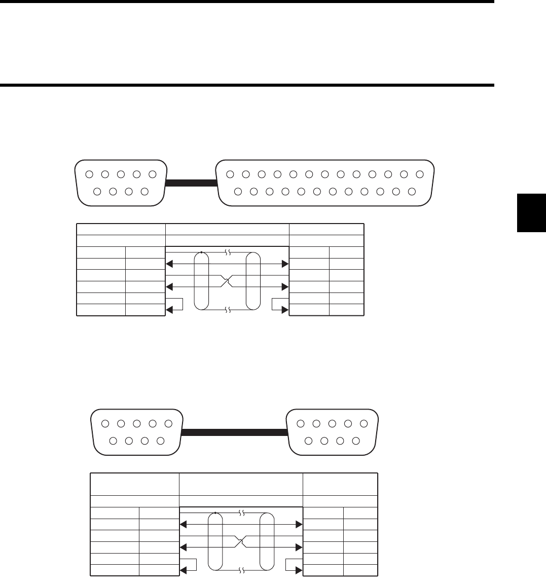
3-1 Controller
3-13
Connecting to a host device of NEC PC-9801 compatible machine, 25-pin
Connecting to the OMRON programmable controller (PLC)
1 5
6 9
113
14 25
Controller Connecting Device
Connector with a cable9-Pin, male
NEC PC-9801 Compatible Machine
25-Pin, male
Shield
(Shielded wire)
FG
SG
SD
RD
RS
CS
1
7
2
3
4
5
5
3
2
7
8
GR
SG
SD
RD
RS
CS
View of fitting face of cable connector
at the controller side
View of fitting face of cable connector
at the host device side
1 5
6 9
1 5
6 9
Controller
Model CS1W-SCU41
Model CJ1W-SCU41
Connecting Device
Connector with a cable9-Pin, male 9-Pin, male
Shield
(Shielded wire)
FG
SG
SD
RD
RS
CS
1
9
2
3
4
5
5
3
2
7
8
GR
SG
SD
RD
RS
CS
View of fitting face of cable connector
at the controller side
View of fitting face of cable connector
at the host device side
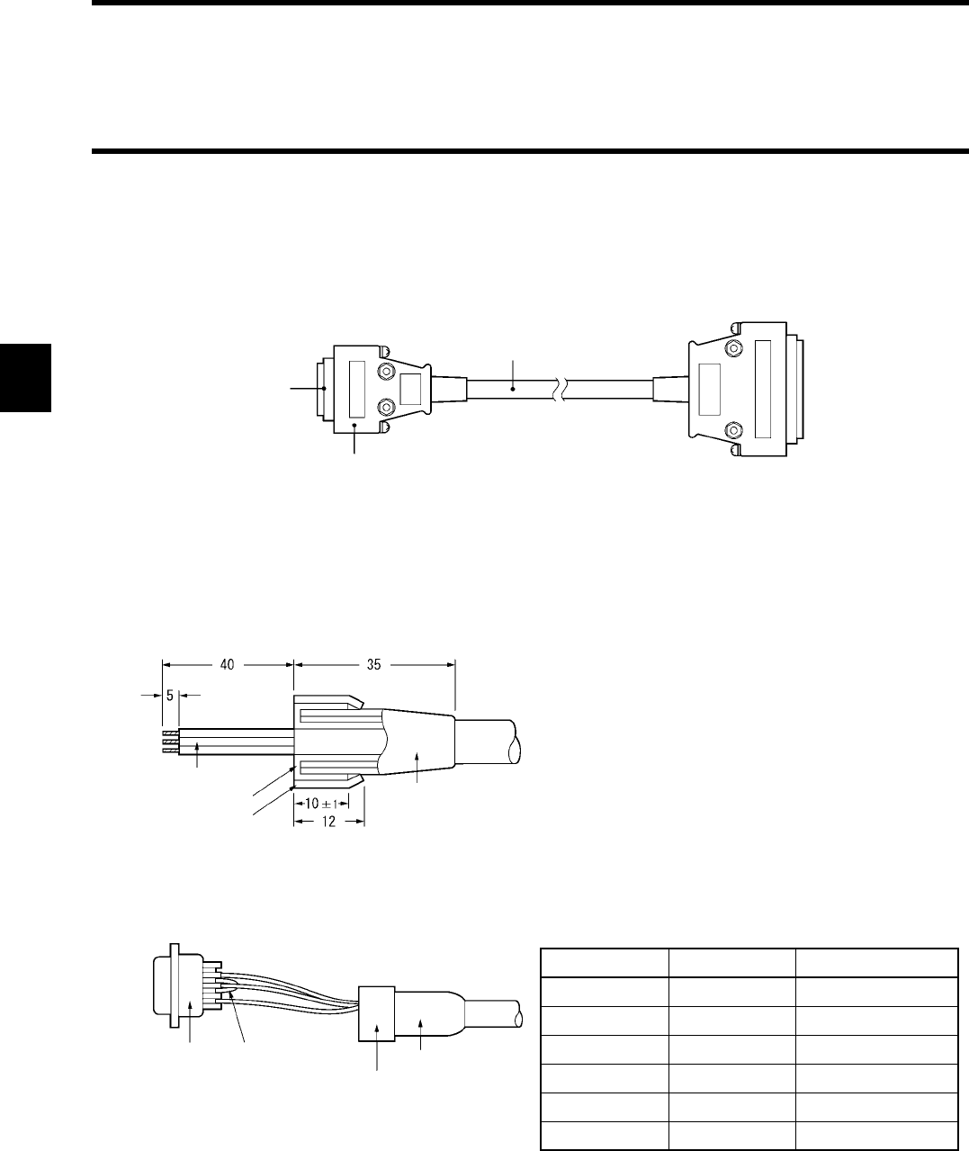
3-1 Controller
3-14
♦Assembling and connecting a connector for communication
Use our connector for communication, which comes with the controller. Prepare a connecting cable and connector for a host computer
by yourself. Our connector which comes with the controller is based on the countermeasures against EMI.
(Instead of our connector which comes with the controller, you may use any other commercial connector. Refer to "Appendix 2 Order
Format List".)
* 1. One set of connectors (based on the countermeasures against EMI) comes with the ID controller.
* 2. You may use any other cable if the cable specifications are the same as ours. (The outer diameter is 7 mm.)
♦How to assemble a connector
(1) Terminate the cable properly.
(2) Solder the core and plug pin.
To the ID controller
Plug
Model XM2A-0901
(which comes with the
controller)
(OMRON)
Hood
Model XM2S-0911 *1
(which comes with the controller)
(OMRON)
•Recommendable cable
CO-MA-VV-SB 5PX28AWG *2
(Hitachi Cable)
Connecting cable
To the host computer
Core
Shield braid
Shield tape
Cable bush
(Unit: mm)
• Fit the cable bush in the cable in advance.
• Ravel the shield braid, turn back it and cover the cable
bush with the shield braid. The length of the shield
braid covering the cable bush should be 10 mm.
• Wind the shield tape on the shield braid.
Plug Crossover
Aluminum tape
Cable bush
Note: Short-circuit No. 7 (RS) and No. 8 (CS) pins with cross-
over.
Pin No. Code Name
Shield GR Ground
5 SG Ground for signal
3 SD Send data
2RDReceive data
7 (Note) RS Request to send
8 (Note) CS Clear to send
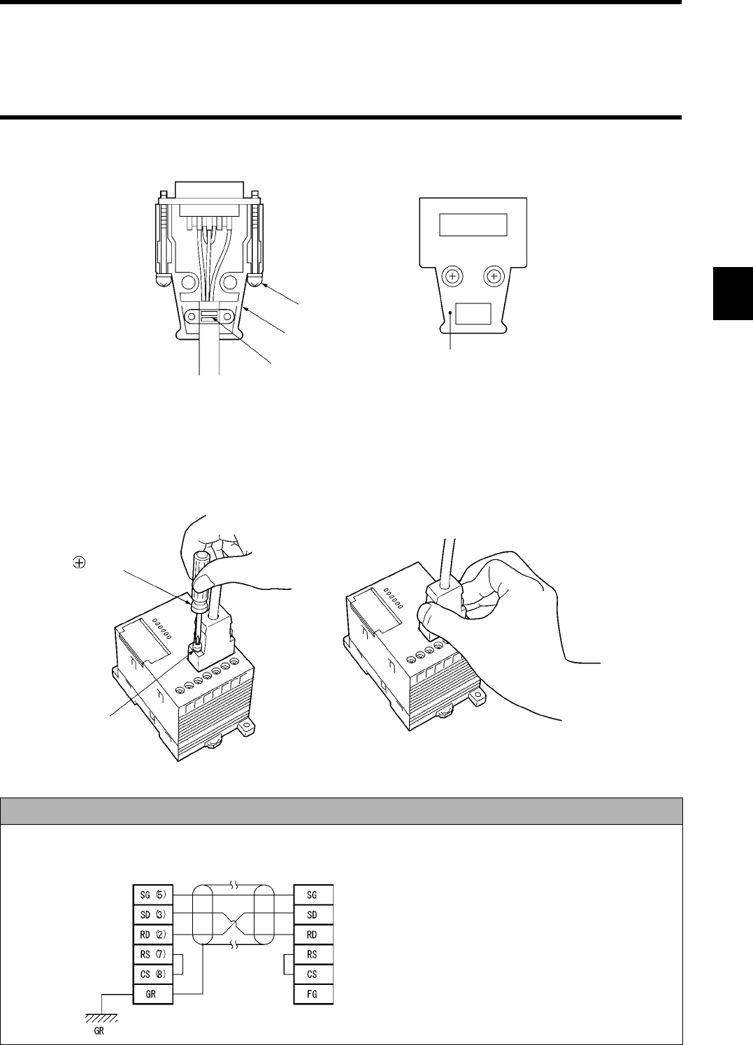
3-1 Controller
3-15
(3) Set the plug in the housing A2 of the hood and fix the aluminum tape with a clamp.
(4) Set the two connector lock screws and put the housing B2 there to complete the connector.
♦How to connect and disconnect a connector
• When you connect the connector, be sure to hold the connector and insert it completely. When you have inserted the connector,
tighten the two lock screws with the Phillips screwdriver.
• When you disconnect the connector, loosen the two lock screws and pull out the lug of connector hood straight. If it is hard to pull
out the connector, hold the controller tightly and pull out it.
Correct Usage
Example of grounding a shielded wire at the controller side:
Lock screw (2-M2.6)
Housing A2
Cable clamp Housing B2
Phillips screwdriver
Lock screw
ID controller Host computer • To prevent an operation error, ground the shielded wire
either at the controller side or the host computer side.
(This figure shows an example of grounding it at the con-
troller side.)
• Short-circuit the RS pin and CS pin inside the connector.
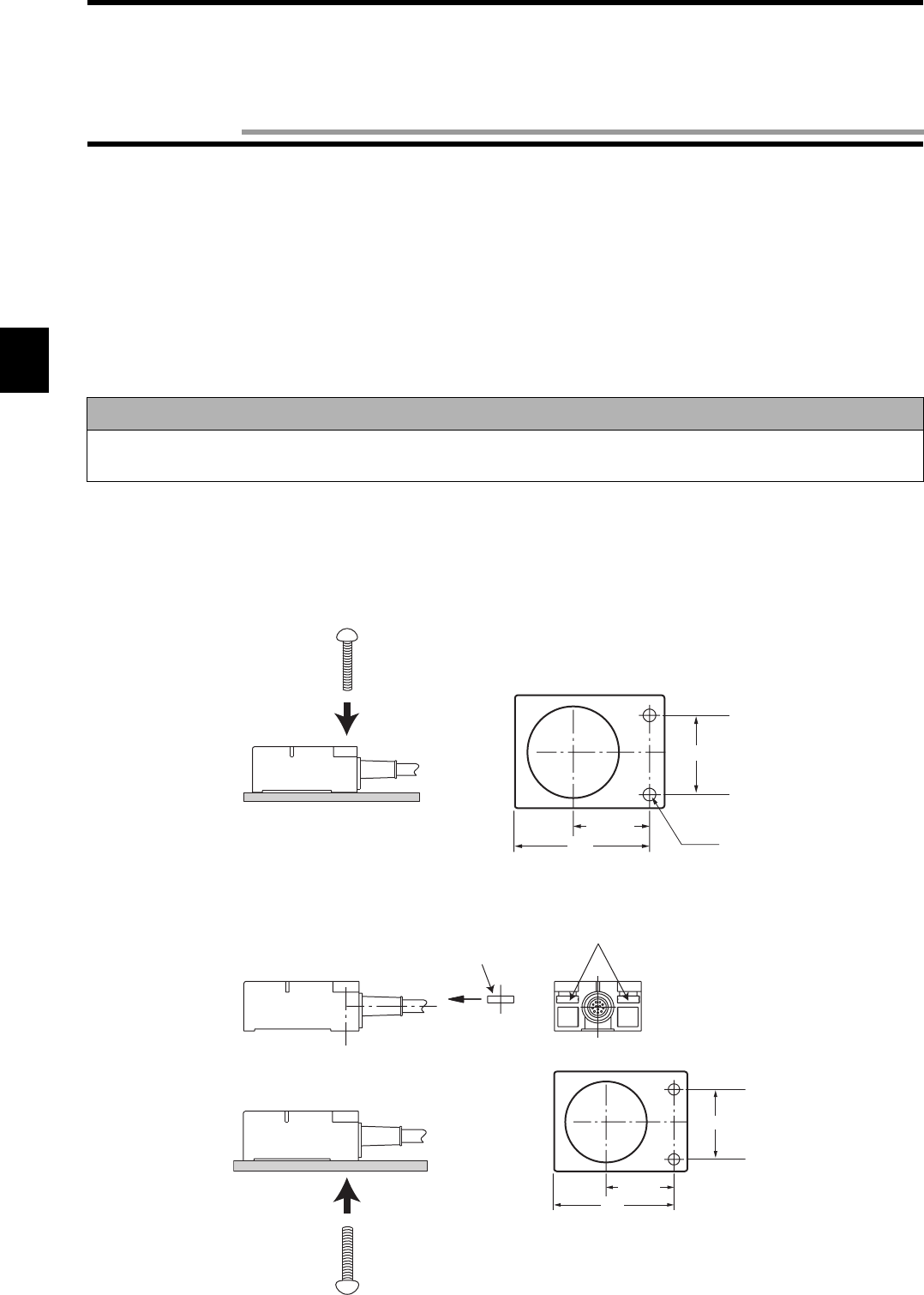
3-16
3-2-1 Installation Site
♦Installation site
Do not install the antenna at any place below:
• Place where the ambient temperature is out of the range between -10 and +70°C, where the temperature fluctuates considerably and
where condensation occurs.
• Place where the relative humidity is out of the range between 35 and 85%RH.
• Place where there is corrosive gas, flammable gas, dust, salt or iron powder.
• Place affected by vibration or impact.
• Place splashed with water, oil or chemicals
3-2-2 How to Install
♦Model V670-H11
•Installation on a surface
•Installation on the back
Insert a nut which comes with the antenna into the section A.
Note
When you install the antenna, be sure to follow the instructions above and test it fully.
In addition, on both inside and outside of the control panel, lay the antenna cables separately from the power cables.
27±0.2
28±0.2
47 2-M4
M4 screw
(Tightening torque: 1.2 N•m or less)
(Unit: mm)
27±0.2
28±0.2
A
47
M4 nut
M4 screw
(Tightening torque: 1.2 N•m or less)
(Unit: mm)
3-2 Antenna
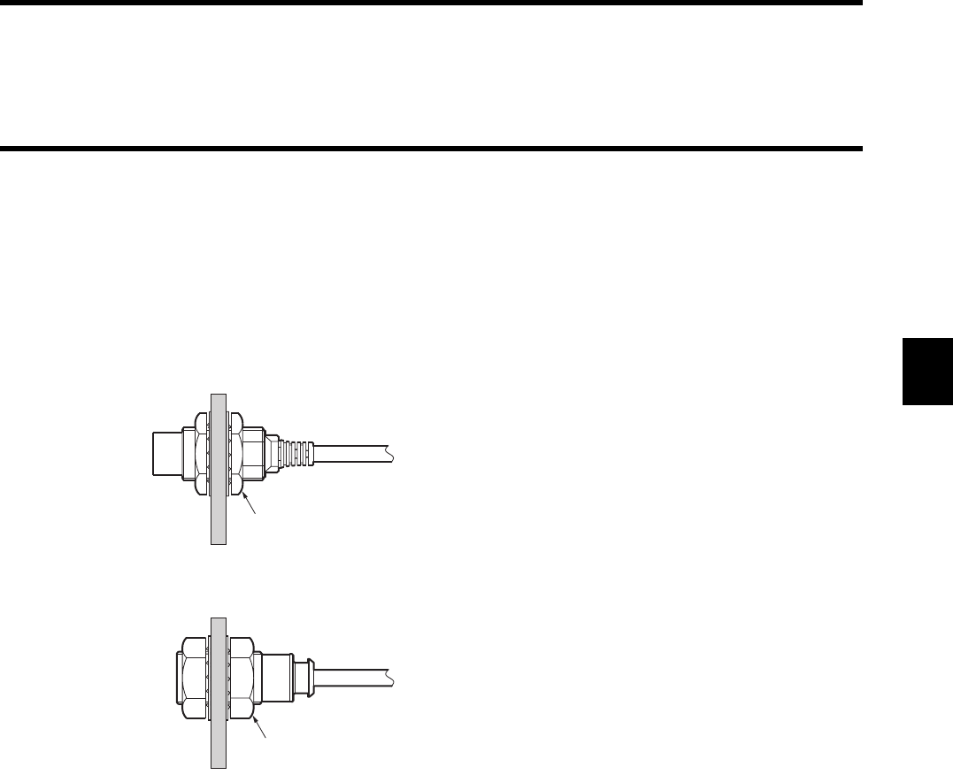
3-1 Controller
3-17
♦Model V670-H51/H51Q
•Installation
When installing the antenna, do not apply large shock to it with a hammer or other tool. Shock may damage the antenna or may
reduce its water resistance.
•Tightening strength
Tighten the nuts to the torque specified below. When tightening the nuts, be sure to use toothed lock washers.
♦Model V670-H51
♦Model V670-H51Q
M18 nuts attached to products
(Tightening torque: 70 N•m or less)
M18 nuts attached to products
(Tightening torque: 2 N•m or less)
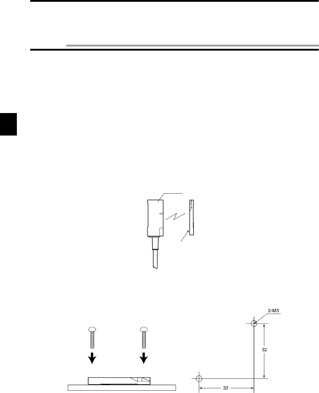
3-18
3-3-1 Installation Site
Do not install the tag at any place below:
• Place where there is corrosive gas, flammable gas or iron powder.
• Place where the ambient temperature is out of the range between -10 and +70°C, where the temperature fluctuates considerably and
where condensation occurs.
• In a microwave oven.
3-3-2 How to Install
Install the tag according to the following instructions:
• Neither shave, drill nor machine the tag.
• Do not apply any excessive force to the tag.
• Neither contact the tag and any metal with each other nor install the tag near any metal.
* When the tag is used in both high temperature and low temperature, the tag may bend. However, the function is not affected.
♦Model V670-D13F03
•Tag installation direction
Install this tag so that the tag surface can be in parallel with the antenna.
•Example of tag installation
Install the tag with the screws.
Antenna
Marking side
M3 screw (Tightening torque: 0.6 N•m or less)
(Unit: mm)
3-3 Tag
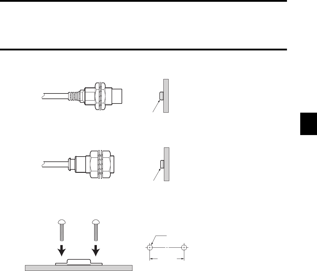
3-1 Controller
3-19
♦Model V670-D13F01
•Tag installation direction
♦Model V670-D13F01H
•Tag installation direction
•Example of tag installation
* Install the tag on a flat surface. Avoid installation on a curved surface.
Marking side
Marking side
M3 screw (Tightening torque: 5 N•m or less)
20.5 ± 0.1
2-M3
(Unit: mm)

3-20
4-1
Depending on an operation sequence, you can specify various communications through the communication command for communica-
tion with a tag. The following seven communication designations are available.
Those seven communication designations are classified into three groups; a command trigger system which starts the communication by
sending a command, auto system which detects a tag automatically and executes the communication, and input trigger system which
start the communication by external input.
According to this classification, the operation of every communication designation is described below.
4-1-1 Designation of Command Trigger System Communication (ST)
In the command trigger system communication designation, the communication with a tag is executed by sending a command and the
controller command processing is ended by terminating the communication. If the tag is not in the communication area when the com-
mand is sent, an error (error code: 72) is returned to indicate that there is no tag in the communication area. Therefore, you must check
the tag in the communication area with a sensor etc. and return a command.
ST designation:
Code Name Description
ST Single command Trigger When the command is received, the communication with the tag is executed and
the response is returned.
SA Single Auto command After the command is received, the communication is executed when a tag has
been detected in a communication area and the response is returned.
SI Single Input trigger After the command is received, the communication with the tag is executed at the
leading edge timing of external input (TRG) and the response is returned.
RA Repeat Auto command "SA" designation is repeated. The communication with the same tag, which
exists continuously, is executed only one time.
RI Repeat Input trigger "SI" designation is repeated.
PA Poling Auto command "SA" designation is executed and the response is returned by the polling query
(PC) command.
PI Poling Input trigger "SI" designation is executed and the response is returned by the polling query
(PC) command.
Tag
Antenna
The communication with tag in the
communication area is executed when
a command from a host is received.
So, if the tag is not in the communica-
tion area, the response is returned to
indicate that there is no tag in the com-
munication area.
Host → Controller
Host ← Controller
Controller ↔ Ta g
(Tag action)
ST mode command
Response *
* Responds whether there is a tag or not.
Communication
End of process
Tag
Chapter 4 Functions
4-1 Communication Designation Function
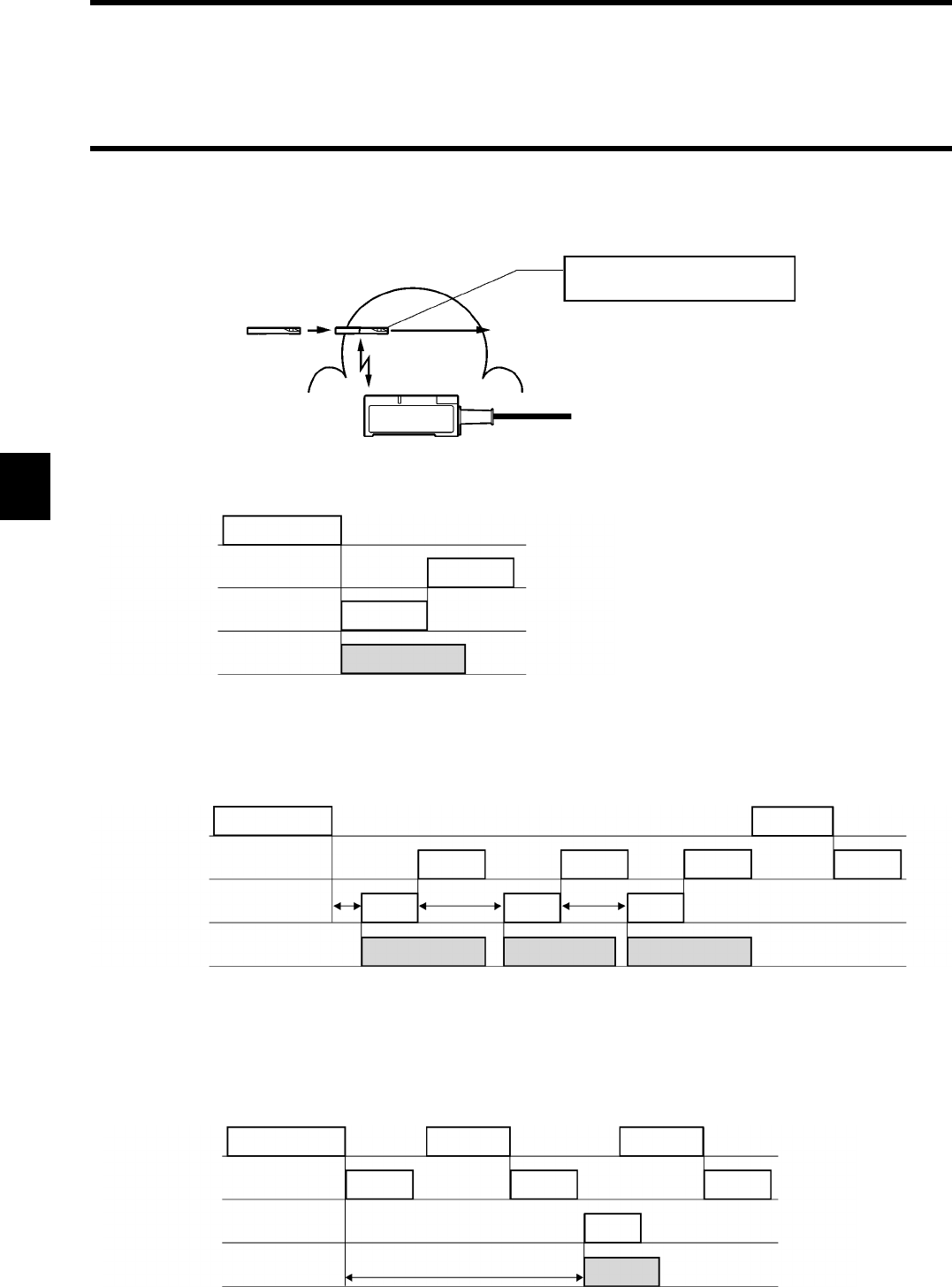
4-1 Communication Designation Function
4-2
4-1-2 Designation of Automatic System Communication (SA/RA/PA)
In the auto system communication designation, a tag is detected automatically. So, unlike the command trigger system, you do not need to check the tag.
SA designation:
For the single designation (SA), the controller command processing is ended by terminating the communication.
RA designation:
For the repeat designation (RA), the system waits until the next tag has come even after the communication is terminated. If the tag
once executes the communication, the tag does not execute the communication until it has moved out of the communication area.
Repeat processing is ended by a command process abort command (AA).
PA designation:
In the PA designation, similarly with RA, processing is repeated until the processing is terminated by a command process abort com-
mand (AA). However, no response is made after the communication with one tag is ended. Response is returned by a polling query
(PC) command instead. Use this designation when several controllers are connected to a host device through RS-485, etc. (Commercial
232C/485 converter is required.)
When the tag enters the communica-
tion area, the communication starts.
Tag
Antenna
Host → Controller
Host ← Controller
Controller ↔ Ta g
(Tag action)
SA mode command
Response
Communication
End of process
Tag
Host → Controller
Host ← Controller
Controller ↔ Tag
(Tag action)
RA mode command
Response
Communication
A
End of
process
Tag A
Communication
B
Communication
C
Tag B Tag B
Response
Waiting for a tag Waiting for a new tag Waiting for a new tag
Response Response
AA command
Host → Controller
Host ← Controller
Controller ↔ Tag
(Tag action)
PA designation command
Response
Tag
Communication
Response
(Acceptance) (No communication)
Response
PC command
PC command
(Result of communication)
End of process
Waiting for a tag
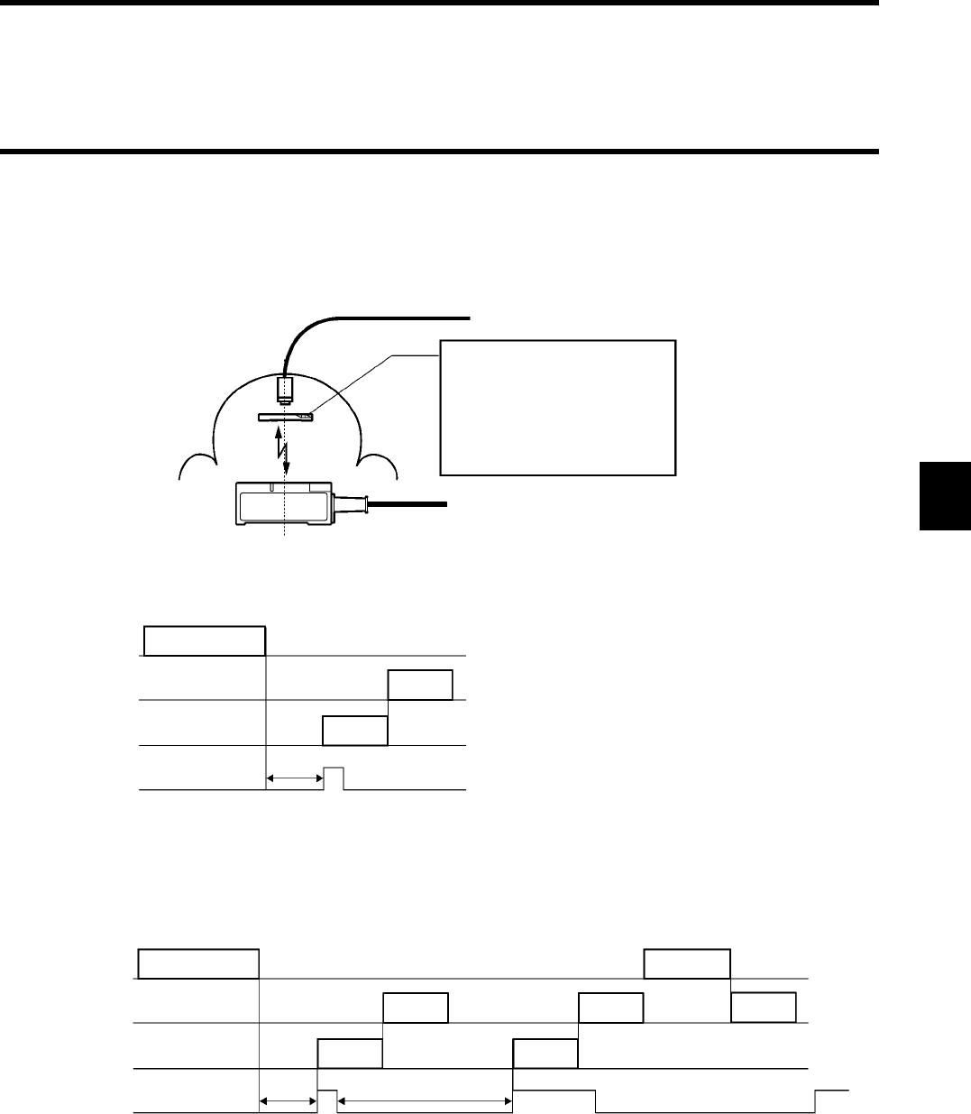
4-1 Communication Designation Function
4-3
4-1-3 Designation of External Trigger System Communication (SI/RI/PI)
In the external trigger system communication designation, the communication is started at a leading edge of an external input signal.
The communication is directly controlled by output of a sensor which detects a tag in the communication area. So, the communication
can be executed even in a fast line without fail.
SI designation:
In the single designation (SI), the controller command processing is ended by terminating the communication.
RI designation:
In the repeat designation (RI), the system waits for a leading edge of the next input signal even after the communication is ended. The
communication is executed to the tag whenever the leading edge of input signal is detected. Repeat processing is ended by a command
process abort command (AA).
To the external input of ID controller
The system waits for a leading edge of an
input signal when a command has been
issued by a host. (An sensor is one of
examples.) The communication is exe-
cuted to the tag in the communication area
at the leading edge of the input signal. If
the tag is not in the communication area,
an error occurs to indicate that there is no
tag in the communication area.
Tag
Antenna
Host → Controller
Host ← Controller
Controller ↔ Tag
External input
SI mode command
Response*
* Responds whether there is a tag or not.
Communication
End of process
Waiting for input
Host → Controller
Host ← Controller
Controller ↔ Tag
External input
SI designation command
Response*
* Responds whether there is a tag or not.
Communication
End of
process
Waiting for
input
Response*
Communication
Waiting for input
Response*
(Terminated)
AA command
4-1 Communication Designation Function
4-4
PI designation:
In the polling designation (PI), similarly with RI, processing is repeated until the processing is terminated by a command process abort
command (AA). However, no response is made after the communication with one tag is ended. Response is returned by a polling query
(PC) command instead. Use this designation when several controllers are connected to a host device through RS-485 etc. (Commercial
232C/485 converter is required.)
Correct Usage
To use the communication designation of SI, RI and PI, turn ON (trigger input) the dip switch 3-1.
Host → Controller
Host ← Controller
Controller ↔ Tag
External input
PI designation command
Response*
Communication
End of process
Waiting for input
PC command PC command
(Acceptance)
Response*
(No communication)
Response*
(Result of communication)
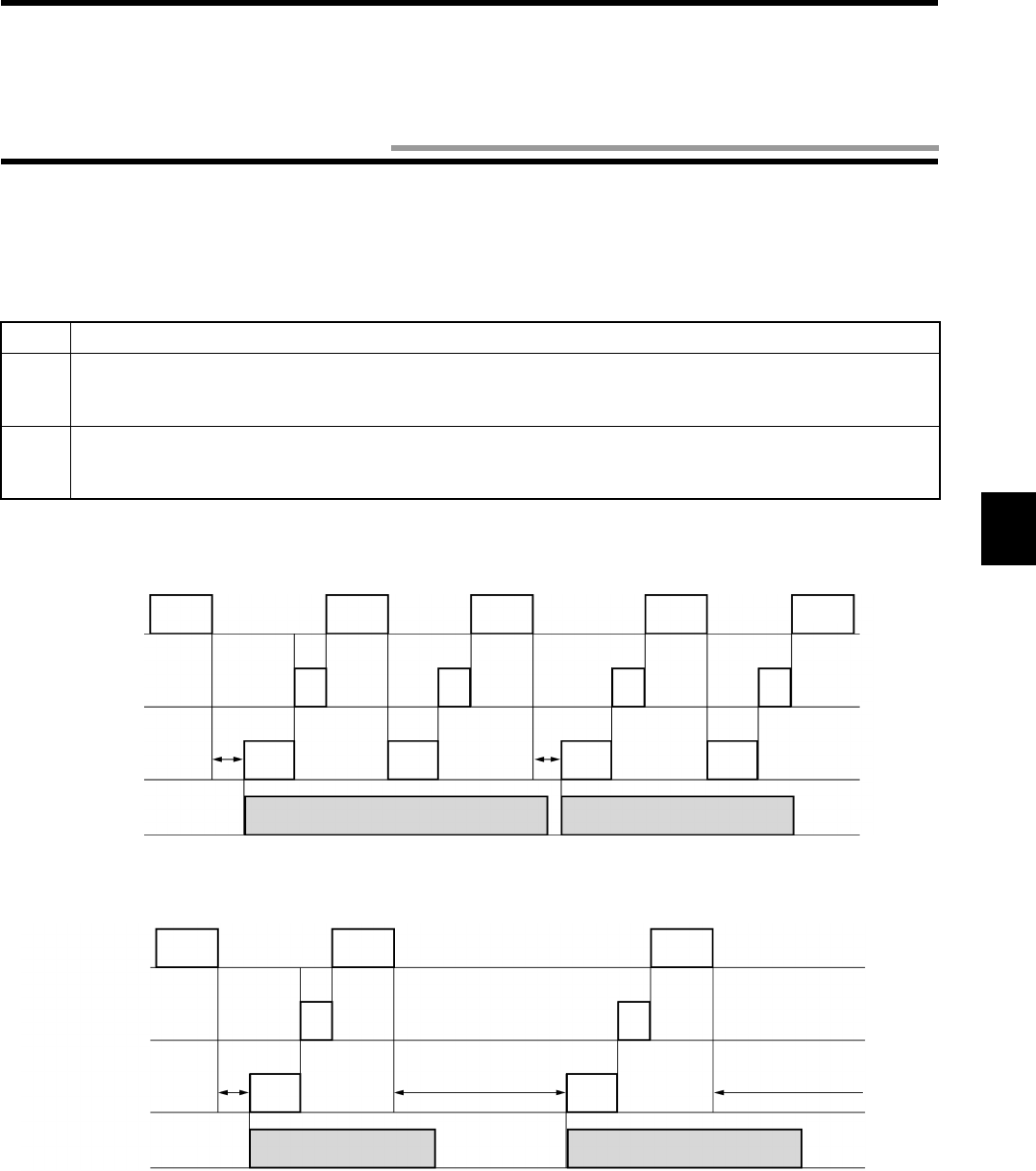
4-5
When reading data or writing fixed data, you can use "Repeat Auto" designation or "Repeat Trigger" designation. However, if you write
different data per tag or if you use several commands (e.g., read → judge → write), you cannot use this function.
To enable this process, you can use the Tag Designation function. By using this function, regardless of timing, you can only send the
commands consecutively to communication with an objective tag without fail. Moreover, a sensor for tag detection is not required. So,
the system configuration can be simplified.
<Example of process sequence>
When you execute a command 1 and command 2 to the tags (A, B, ...) moving continuously, you can use the following sequence.
When you write different data into the tags (A, B, ...) moving continuously, you can use the following sequence.
Code Description
“sa” When a tag enters the communication area, the communication to the tag is executed. The communication is
made to any tag other than the tag to which the communication has been executed immediately before. If the
same tag exists continuously, the system waits until any other tag enters the communication area.
“st”
When a command has been received, the communication is executed to the tag in the communication area. The communi-
cation is made to the same tag to which the communication has been executed immediately before. Even if any different tag
is in the communication area, an error occurs to indicate that there is no tag in the communication area.
Host
↓
Controller
Host
↑
Controller
Controller
↓↑
Tag
Tag
in communication
area
Command 1
(sa
designation)
Command 2
(st
designation)
Command 1
(sa
designation)
Command 2
(st
designation)
Response Response Response Response
Waiting
for a new
tag
Commu-
nication
1A
Waiting
for a new
tag
Previous ta g
only
Commu-
nication
2A
Commu-
nication
1B
Commu-
nication
2B
Previous tag
only
Tag A Tag B
Command 1
(sa
designation)
Host
↓
Controller
Host
↑
Controller
Controller
↓↑
Tag
Tag
in communication
area
Command 1
(sa
designation)
Command 2
(st
designation)
Response
Waiting
for a new
tag
Commu-
nication
A
Tag A
Command 2
(sa
designation)
Response
Waiting for a new tag Commu-
nication
B
Waiting for a new tag
Tag B
4-2 Tag Designation Function
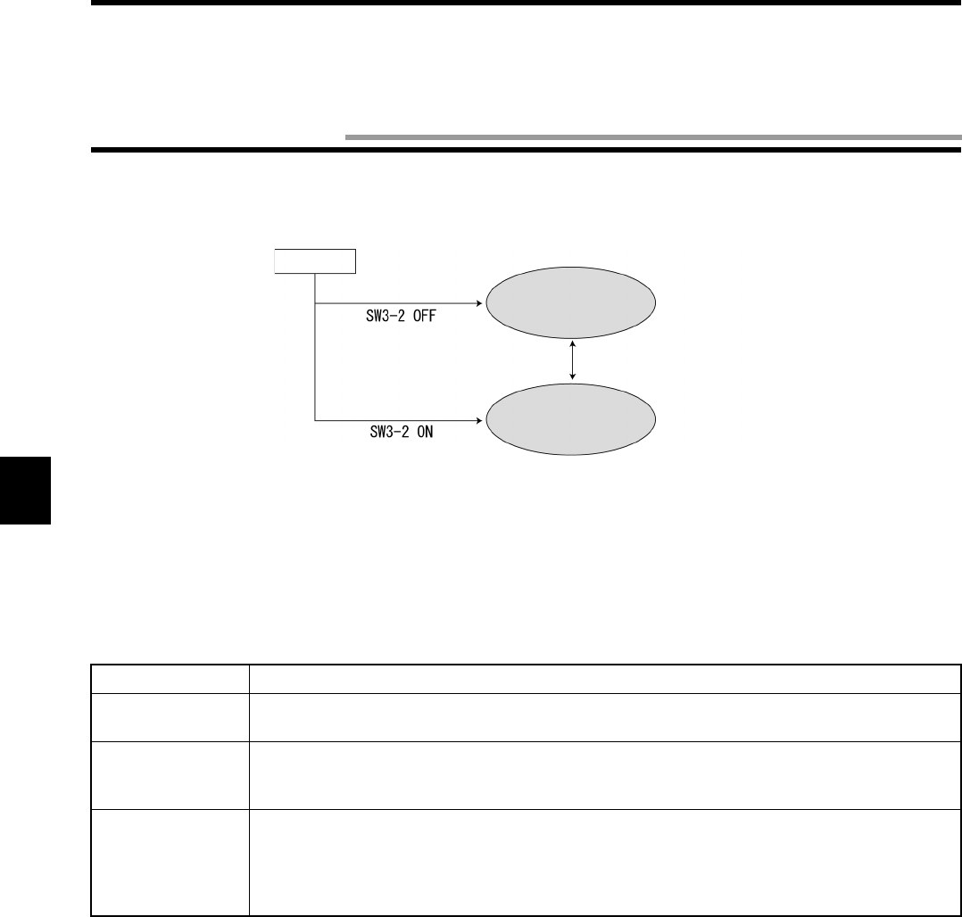
4-6
There are two operation modes, i.e., Command Execution mode and Self-Execution mode. Through the dip switch 3-2, you can specify
one mode of them to be started at the power ON. Also, you can change the mode by a mode change command (MO) from a host device.
(1) Command Execution mode
The communication is executed by an instruction (command) from a host device. In this mode, you can use all the command. All,
you can read/control the external I/O terminals (IN, OUT1 and OUT2) by a command from a host device.
(2) Self-Execution mode
The communication to a tag is executed automatically according to the operating conditions registered in the controller, the commu-
nication result can be judged (judgment conditions), and the self-completion operation, to which is output to the two external out-
puts (OUT1 and OUT2) or to the RS-232C port (result output), can be performed. The ID system does not need to be controlled
from a host device. So, a simplified system can be built up very quickly. The following operating conditions can be registered.
The preset operating conditions are stored in nonvolatile memory in the controller. So, you do not need to set them at every power on.
Item Description
Execution process A communication command only can be used. An available communication mode is RA or RI
only.
Judgment condi-
tions
One of the conditions below can be specified per output.
1) Judges the communication result and generates output.
2) Compares response data and set data with each other and generates output.
Result output When a preset judgment condition has been met, the three outputs below can be specified. The
judgment condition can be specified per output.
1) Outputs to OUT1. Output time can be specified.
2) Outputs to OUT2. Output time can be specified.
3) Responds to RS-232C.
Power ON
Command Execution
mode
Self-Execution mode
Mode change command (MO)
4-3 Operation Mode
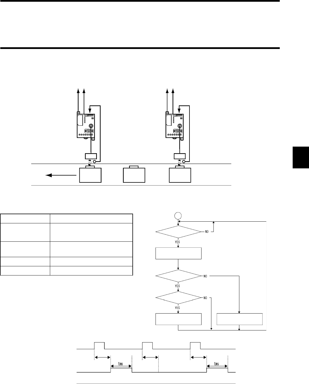
4-3 Operation Mode
4-7
<Example of usage>
When data is read out of the tag into which destination information has been written, the applicable destination only is detected and the
pulse is output, and reading could not be done due to any trouble, an error pulse is output as shown below.
•Setting and operation flow
Setting of operating conditions
Item Description
Execution process Communication command: RD
Communication mode: RI
OUT1 Outputs OUT1 in tms at data
matched.
OUT2 Outputs OUT2 at abnormal end.
RS-232C Nil
Error output Coincidence
output
Trigger input
(Synchronization sensor)
Antenna
Tag
Fast movement
Error output Coincidence
output
Trigger input
(Synchronization sensor)
Trigger input (IN)
Coincidence output (OUT1)
Abnormal output (OUT2)
Communication process
Data matched
Communication process
Data unmatched
Communication process
Data matched
Power ON
TRIG input
Data read (E)
Correct end
Data matched(D)
Coincidence
output pulse
Abnormal output
pulse
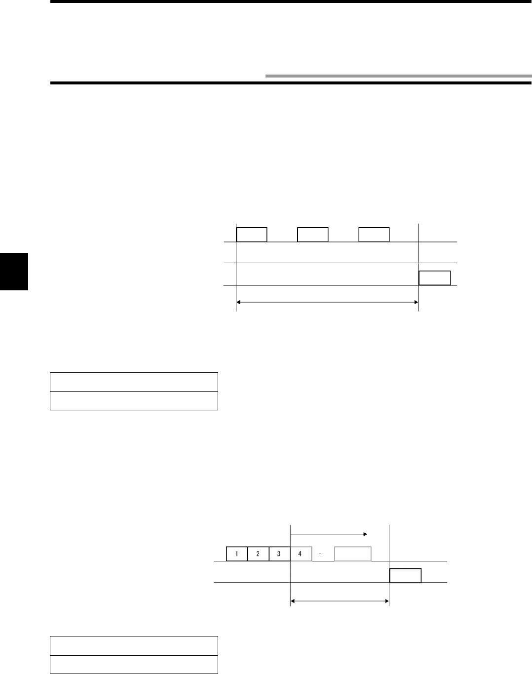
4-8
In the controller, you can specify the operation parameters (Communication Restriction Time, Character Interval Monitoring Time and
Response Delay Time) according to your system to optimize the performance and reliability.
Usually, you may use the default values. However, this setting allows you to optimize your system. Those parameters are stored in non-
volatile memory in the controller. So, the parameters are not erased even if the power supply turns off.
4-4-1 Communication Restriction Time
In the communication to a tag, if a response cannot be made correctly due to any trouble at the communication after tag detection,
"Retry" is executed to send the same command again.
By specifying the communication restriction time, retry is repeated until the specified time has passed after the command process starts.
In the external trigger system command, command process starts when the command process starts. In the auto system command, com-
mand process starts when the tag has been detected.
* If the default value is set, "retry" is repeated 9 times.
4-4-2 Character Interval Monitoring Time
In the controller, a command is recognized by receiving a termination code of command string sent from a host device. However, if the
entire command string cannot be received completely due to any trouble, receiving is monitored for a specified time after the last char-
acter is received. Then, a format error (14) is returned.
* The default value is 100 ms.
Setting Range
10 to 990 ms. A default value is 0.
Setting Range
0 to 9999 ms.
Controller → Tag
Controller ← Tag
Host ← Controller
External input
Send Send Send
Retry Retry
Communication restriction time
Response
Error 72
Host → Controller
Host ← Controller
External input Character interval monitoring time
If there is no data any more
Termination
code
Error 14
Response
4-4 Operation Parameter Setting
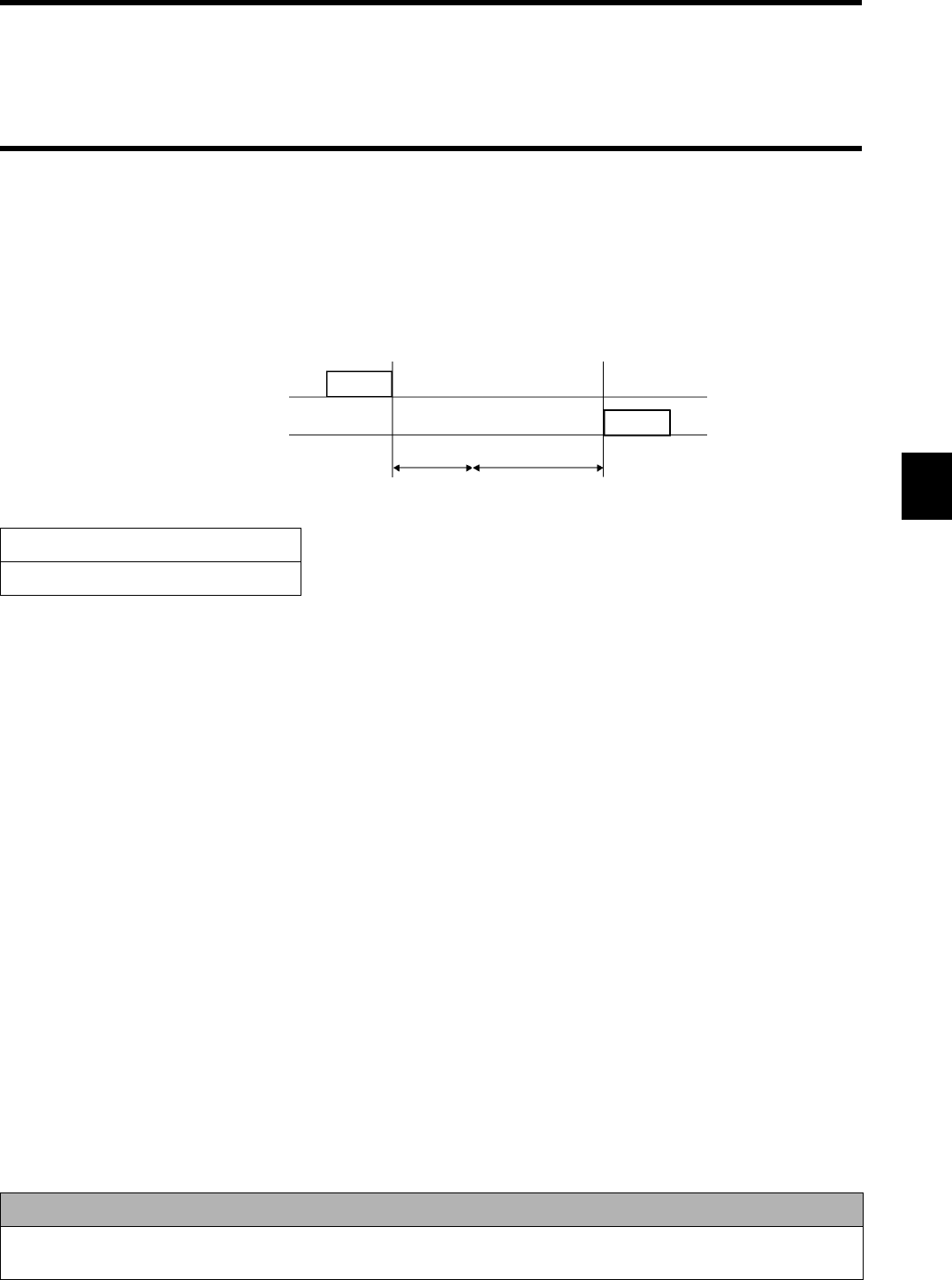
4-4 Operation Parameter Setting
4-9
4-4-3 Response Delay Time
When several controllers are connected to a host device through RS-485 etc. (commercial 232C/485 converter is required), RS-485
switches into receiving after data string is sent. Switching time varies depending on a converter. So, if a response from the controller is
fast, the communication cannot be executed correctly.
By specifying the Response Delay time, the response start time can be changed.
* Actual time from the transmission of command to the start of response is internal process time (a minimum time is 0 ms) of the con-
troller + Response Delay time (specified time).
* The default value is 0 ms.
Setting Range
0 to 9999 ms.
Correct Usage
For how to use the operation parameter setting (SP) command, refer to the description of "5-8-6 Parameter Setting
(SP)".
Host → Controller
Host ← Controller
External input
Response
Internal process time
Response Delay time
Command
4-10
By adding a check code to a data in a tag, you can detect a data error arisen from memory rewrite life or unintentional factor. A CRC
code of generating polynomial X16 + X12 + X5 + 1 is used as the check code.
For memory check, a memory check command (MC) to write a check code and a memory calculation command (MK) to verify the
check code are used.
In a check block specified by the first address and the number of
bytes, an area excluding the last 2 bytes of the block is a target area
to be calculated and the last 2 bytes are a check code area.
When a command to write the check code is sent, the CRC code of
data in the target area for calculation is calculated and it is written
into the check code area. When a data verification command is
sent, the CRC code of data in the target area for calculation is cal-
culated and it is compared with data of the check code area. If
those data match, "0" is returned. This shows that the data is cor-
rect in a response status flag. If those data do not match, "1" is
returned as warning.
<How to use>
Calculate/write the check code with the memory check command (MC) after writing a data and verify the check code with the memory
calculation command (MK) before reading it. Beforehand, you can detect data corruption in the tag which is not accessed.
Writing stage
Reading stage
Data writing
Check code calculation
Check code verification
Data reading
4-5 Memory Check Function
Add
ress
First address in this
area →
Target area for check code
calculation
(Number of check block
bytes: 2)
Check code area (2 bytes)
(High order
(Low order
digit)
digit)
4-11
The Write Protect Function prevents a fixed data, such as pallet information or product information stored in memory in a tag, being
erased by careless writing.
By setting protect information in the tag, Write Protect can be enabled in any area (a maximum of two areas) of a specified address. If
you try to write anything into a write-protected page, a Protect error occurs.
The protect area information is set by using a part (address $0000 to 0003) of user data area.
To enable the Write Protect, write the protect area information into a specified address and specify "Protect Setting" with process desig-
nation parameter using a tag function setting command (TF). Similarly, to disable the Write Protect, specify "Disable" with the process
designation parameter.
♦Relation between Protect information and Protect area
* Available range of Protect area: 0004h to 007Fh
User Address Description Example of data
$0000 Start address of Write Protect area 1 05h
$0001 End address of Write Protect area 1 10h
$0002 Start address of Write Protect area 2 70h
$0003 End address of Write Protect area 2 75h
$0004
User Area
$0005
Write Protect area 1
.
.
$0010
$0011
.
.
$006F
$0070
Write Protect area 2.
.
$0075
$0076
$007F
Correct Usage
If you use the Write Protect function, the area $0000 to 0003 cannot be used as a data area. Also, if you enables the
Write Protect function, the communication time is prolonged (approximately 3 ms).
4-6 Write Protect Function

4-12
5-1
The V670 series RFID system communicates with a tag ((2)) according to the instruction of a command ((1)) sent from a connected host
device and returns the result to the host device as the response ((3)).
♦Controller operation status
•Waiting for command
This refers to the status that the controller does not execute any command process. Then, the controller can accept all the commands
except the subcommands etc. When the controller has accepted any command, the controller enters the command processing status.
•Command processing
When the command has been accepted, the next command is ignored until the process of such accepted command is completed. How-
ever, a command process termination command and reset command can be accepted always.
Host Device Controller
Communication
Antenna Tag
Communication between
the antenna and tag
(1)
(3)
(2)
Command
Response
Chapter 5 Control From Host Device
5-1 Controller Operation Status
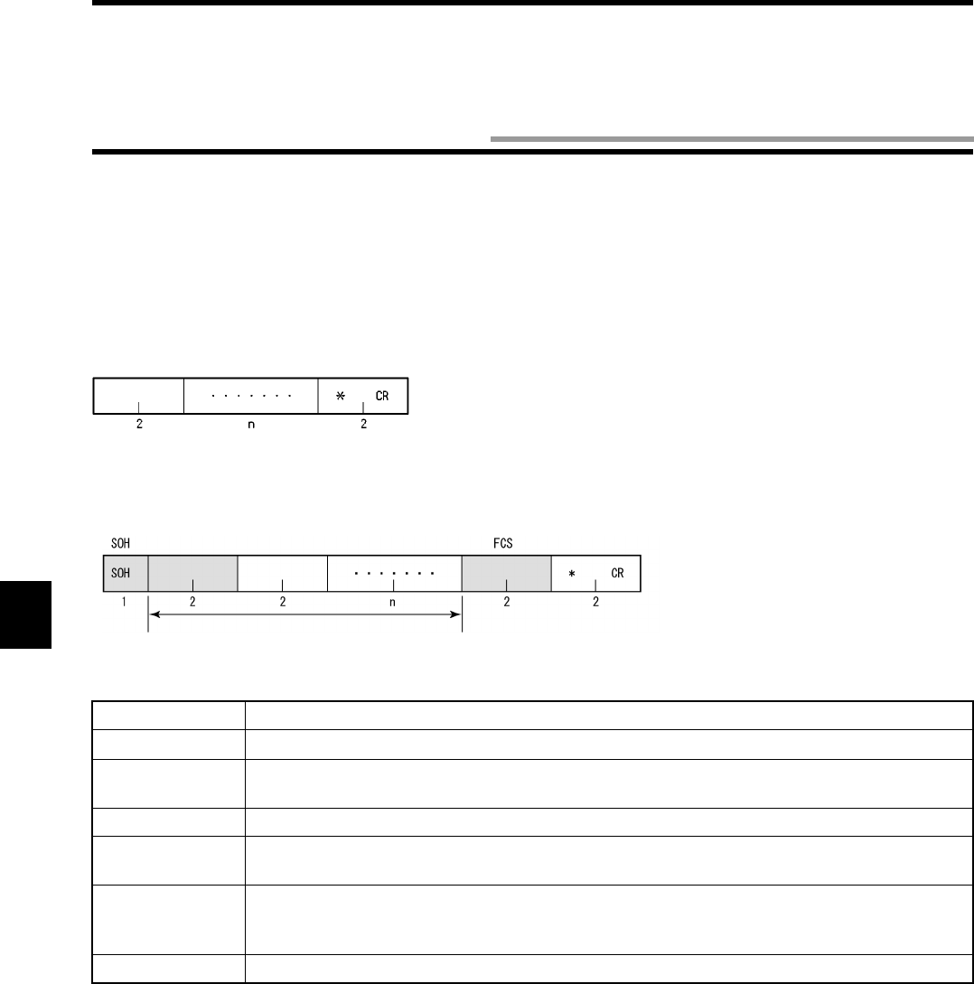
5-2
For the format of command and response communicated between a host device and controller, there are 1:1 protocol used usually and
1:N protocol used to connect several controllers and the configuration is described below.
The protocol is specified through the dip switch (SW3-4) of the controller.
(1) Command frame
1:1 Protocol
1:N Protocol
* In the 1:N protocol, a gray part is added.
Name Description
SOH Shows the beginning of the frame with SOH ($01).
Node No. A number to identify a target controller at the 1:N connection. Specify it through a rotary switch
(SW1/2).
Command code Specifies the execution (command).
Data Specifies the parameters (address, number of bytes, etc.) for the command execution or a data to
be written.
FCS Frame check sequence. This is a code to detect an error in data string. This expresses a calcula-
tion value of horizontal parity of character string between immediately after SOH and immediately
before FCS in two ASCII characters.
Terminator Shows the end of command with two characters, "*" ($2A) and CR code ($0D).
Command code Data Terminator
Node No. Command code Data Terminator
Calculation range of FCS
5-2 Command Response Format
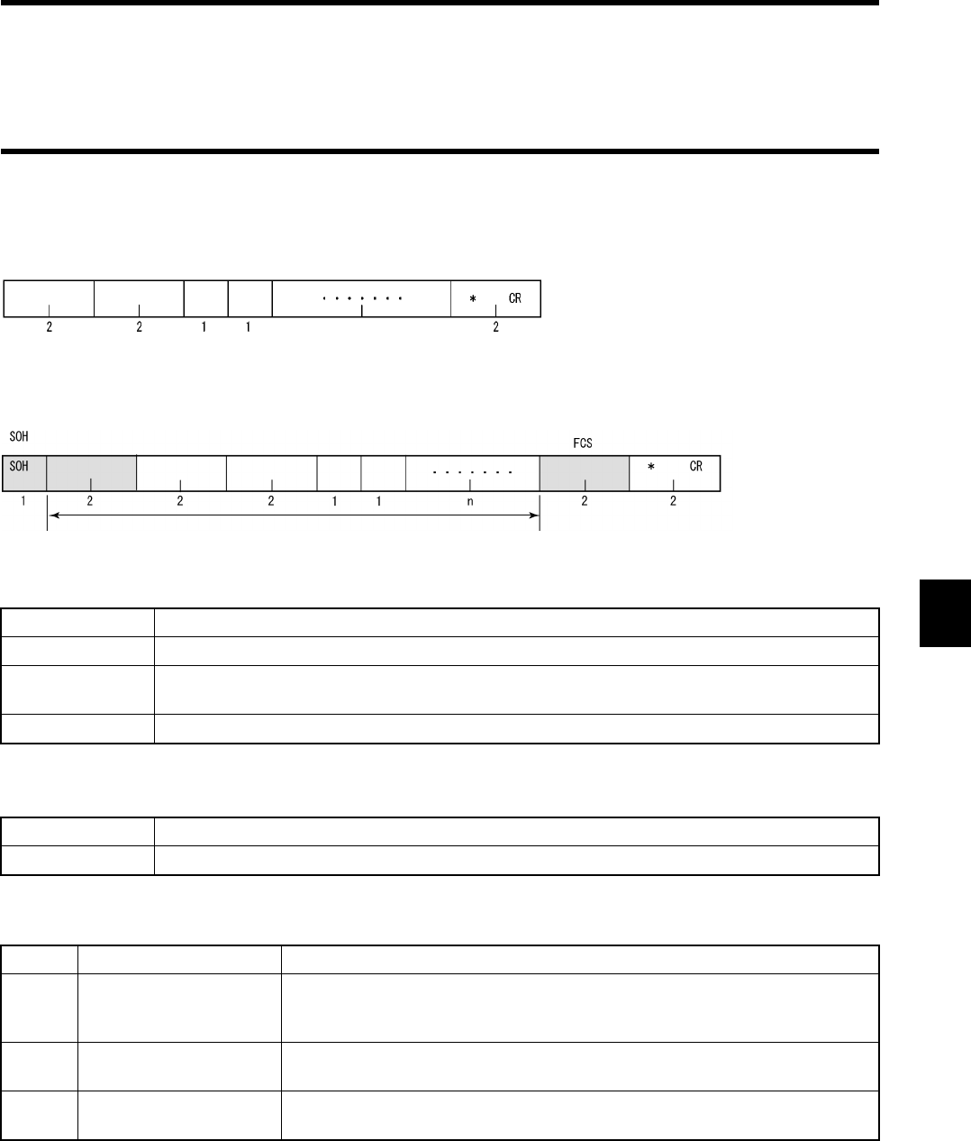
5-2 Command Response Format
5-3
(2) Response frame
1:1 Protocol
1:N Protocol
* In the 1:N protocol, a gray part is added.
* For any part other than the above-mentioned, the same data as the sent command frame is added and returned.
♦Retransmission flag
♦Status flag
Name Description
Termination code Shows the command execution result.
Retransmission
flag
Flag to show the response to retransmission. This is "1" at retransmission.
Status flag Code to show the command execution status.
"0" Response after usual command process.
"1" Response returned by a request to retransmit data (RR).
"0" Communication status Shows that process has been executed correctly.
"1" Tag data status Shows that the verification result of data check command (MD) is invalid or that
overflow/underflow has occurred in the calculation of a calculation writing com-
mand (CW).
"2" Abort status Shows that communication to a tag has been aborted after the start by an abort-
ing command (AA).
"4" Polling acceptance Shows that the polling status is enabled by accepting the communication desig-
nation "PA (pa)" or "PI".
Command code Termination code
Retransmission
flag
Status
flag
Data Terminator
n
Command code Termination code
Retransmission
flag Status
flag
Data Terminator
Node No.
Calculation range of FCS
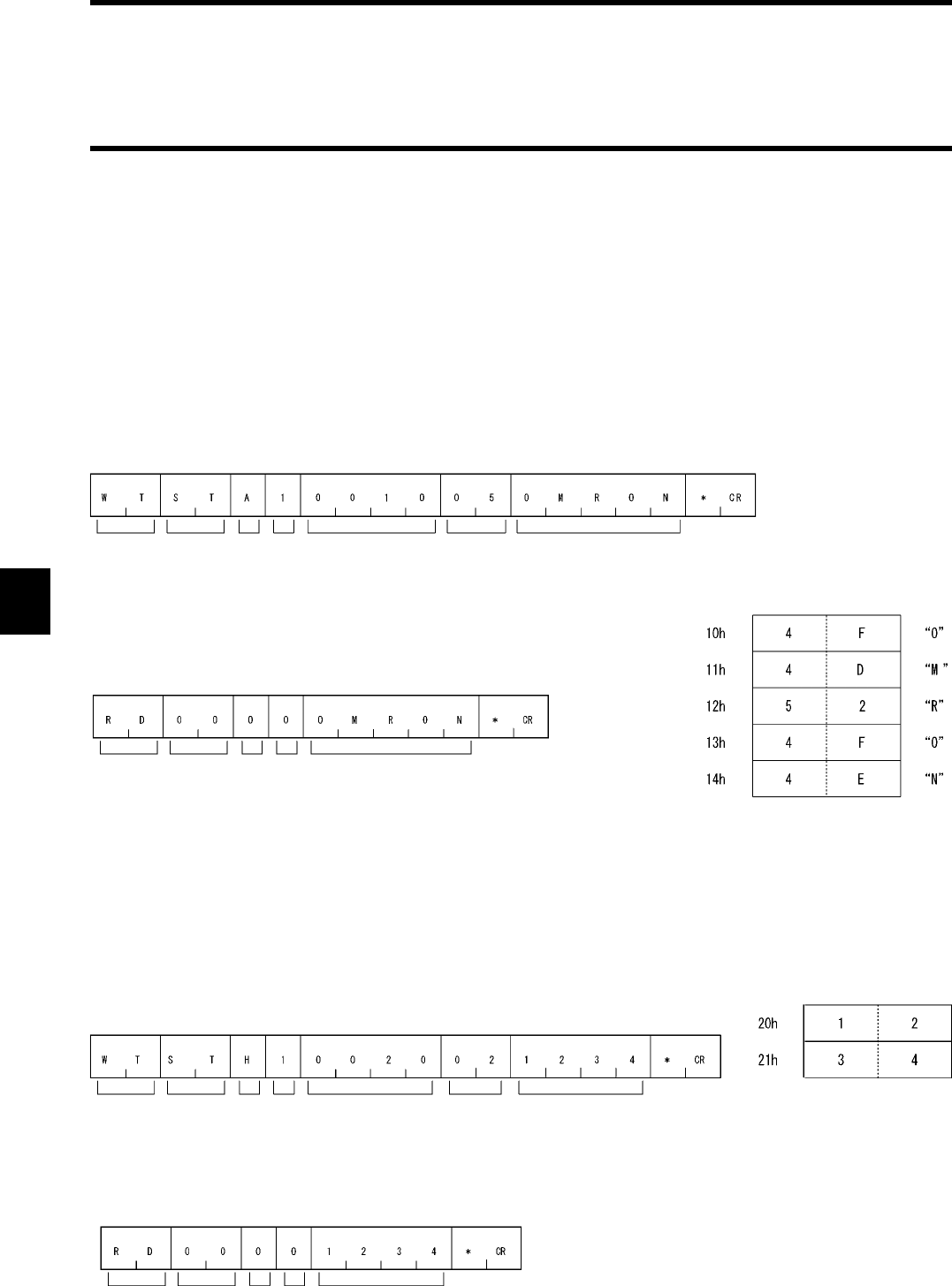
5-2 Command Response Format
5-4
(3) Data code designation
You can specify in a command a code to be used to transmit a data to be read or written between a host device and ID controller. ASCII
code designation and hexadecimal code designation are available.
•ASCII code (JIS8 unit code) designation "A"
1 Byte of data in a tag is transmitted directly as ASCII code or JIS8 unit code. Transmitted one character is equivalent to 1 byte of data
in a tag. Character data can be read/written directly. However, do not use any control code [SOH] nor [CR] in a data to be transmitted.
If [SOH] or [CR] is specified in a written data, a command error occurs.
<Example of writing>
If you specify "OMRON" as a written data in 5 bytes of memory beginning with the address 10h, the data is written in memory in a tag
as shown in this figure.
<Example of reading>
•Hexadecimal code designation "H"
1 Byte of data in a tag is converted into two hexadecimal characters ("00" to "FF") and transmitted. Transmitted two character is equiv-
alent to 1 byte of data in a tag. Be sure to specify a written data with every two characters "00" to "FF" (even number). If any data of
odd number of characters is specified, a command error occurs.
<Example of writing>
If you specify "1234" as a written data in 2 bytes of memory beginning with the address 20h, the data is written in memory in a tag as
shown in this figure.
<Example of reading>
If you read 2 bytes of memory beginning with the address 20h, the read data is "1234" in the data shown in this figure.
<Command>
Command
Communication
designation
ASCII
designation
Antenna
designation
First address Number of
bytes
Written data
Command
Termination code
Read data
Retransmis-
sion flag
Stavtus
flag
Memory in tag
Address
If you read 5 bytes of memory beginning with the address 10h,
the read data is "OMRON" in the data shown in this figure.
<Command>
Command
Communication
designation
ASCII
designation
Antenna
desivgnation
First address Number of
bytes
Written data
Memory in tag
Address
<Response>
Command
Termination code
Read data
Retransmis-
sion flag
Status
flag
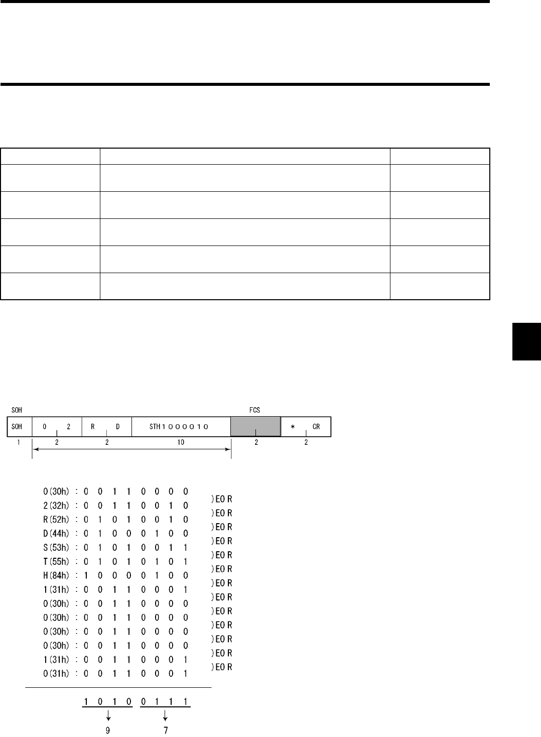
5-2 Command Response Format
5-5
(4) Available designation range of first address and number of bytes
A command to specify the first address and the number of bytes in a command and the available designation range are shown in the
table below. If you specify any value out of the available range, a command error occurs.
* If the first address is 20h and the number of bytes is 70h, a command error occurs due to "A + B = 90h".
(5) Example of calculation of FCS
Exclusive-OR is executed from the node number to the end of data at every 1 byte. The result is converted into an ASCII code and
added.
Reading 16 bytes from the address 0000h
Command code Available designation range of first address and number of bytes Other restriction
Read (RD) A) Available designation range of first address: 0000h to 007Fh
B) Available designation range of number of bytes: 01h to 80h
A + B ≤ 80h*
Write (WT) A) Available designation range of first address: 0000h to 007Fh
B) Available designation range of number of bytes: 01h to 80h
A + B ≤ 80h*
Computation Write
(CW)
A) Available designation range of first address: 0000h to 007Fh
B) Available designation range of computation area: 01h to 80h
A + B ≤ 80h*
Data Fill (DF) A) Available designation range of first address: 0000h to 007Fh
B) Available designation range of end address: 0000h to 007Fh
A ≤ B
Memory Check (MD) A) Available designation range of first address: 0000h to 007Dh
B) Available designation range of number of check bytes: 03h to 80h
A + B ≤ 80h*
Command code Terminator
Data
Node No.
Calculation range of FCS
Calculation result
79
5-6
Depending on a type of command and the communication designation, receiving the command from a host device to the controller and
the response to the host device vary.
(1) No response
When the controller receives a reset command, the controller does not send any response, performs resetting and waits for a command.
(2) Single response
When single trigger (ST/st), single auto (SA/sa), single input trigger (SI), polling auto (PA/pa) or polling input trigger (PI) is specified
by a command to communicate with the tag, or when a command not for the communication with the tag (communication subcommand,
controller control command or host command) is specified, one response is returned to one command.
(3) Several responses
When repeat auto (RA) or repeat input trigger (RI) is specified by a command to communicate with the tag, several responses are sent to
one command.
Host Device
Controller
Reset Command
Execution of Resetting
Host Device
Controller
Command
Response
Host Device
Controller
Command
Response Response Response Response
5-3 Command Response Flow
5-7
The commands are classified mainly into four categories.
(1) Communication command
Command to communicate with a tag.
(2) Communication subcommand
Subcommand used to inquire the execution result or abort the execution when polling auto command is used.
(3) Controller control command
Command used to terminate the communication with the tag or reset the controller.
(4) Host command
Command used for a communication test between the controller and host device.
* For the use of self-execution mode, refer to Chapter 6, "How to Use Self-execution Mode."
Command
Type
Command
Code Name Description Use of self-
execution mode
Communication
command
RD Read Reads a data from memory in a tag. ×
WT Write Writes a data into memory in a tag. ×
CW Computation Write Writes the calculation result of
memory data into a tag.
×
DF Data Fill Fills a specified area with specified
data.
×
MD Memory Check Specifies/verifies a check code of
memory in a tag.
×
TF Tag Function
Designation
Specifies/cancels the Write Protect
function to a tag.
×
ID ID Read Reads a user ID in a tag. ×
Communication
subcommand
AA Command Processing
Abort
Aborts communication with a tag. ×
PC Polling Query Inquires polling process. ×
Controller control
command
MO Operation Mode
Change
Switches the Self-Execution mode/
Command execution mode.
RR Data Retransmission Requests to send again the last
data.
XZ Reset Resets the controller.,
CC Controller Control Controls/checks I/O of the
controller.
×
SE Operation Condition
Setting
Registers operation conditions in
the Self-Execution mode.
×
SP Parameter Setting Perform controller setting. ×
Host command TS Test Sends a data received from a host
device.
×
VS Version Information Reads a version of software of the
controller.
×
5-4 Command List

5-8
A communication command can specify the following ten types of communication designation:
Communication
designation
code
Name Description
ST Single trigger When a command has been received, the communication with a tag is
executed and the response is returned.
st Tag-specified single trig-
ger
The communication with the tag to which the last communication was
executed and the response is returned. This operation is the same as
the single trigger (ST).
SA Single auto After the command is received, the communication is executed when
a tag has been detected in a communication area and the response is
returned.
sa Tag-specified single auto The communication with any tag other than the tag to which the last
communication was executed and the response is returned. This
operation is the same as the single auto (SA).
SI Single input trigger After the command is received, the communication with the tag is exe-
cuted at the leading edge timing of external input (TRG) and the
response is returned.
RA Repeat auto "SA" designation is repeated. The communication with the same tag,
which exists continuously, is executed only once. Processing is termi-
nated by an abort command.
RI Repeat input trigger "SI" designation is repeated. Processing is terminated by an abort
command.
PA Polling auto "SA" designation is executed and the response is returned by a query
(polling). Acceptance response is made when a command has been
received.
pa Tag-specified polling auto The communication with any tag other than the tag to which the last
communication was executed and the response is returned. This
operation is the same as the palling auto (PA).
PI Polling input trigger "SI" designation is executed and the response is returned by a query
(polling). Acceptance response is made when a command has been
received.
Correct Usage
For details of communication designation, refer to "4-1 Communication Designation Function".
5-5 Communication Designation List
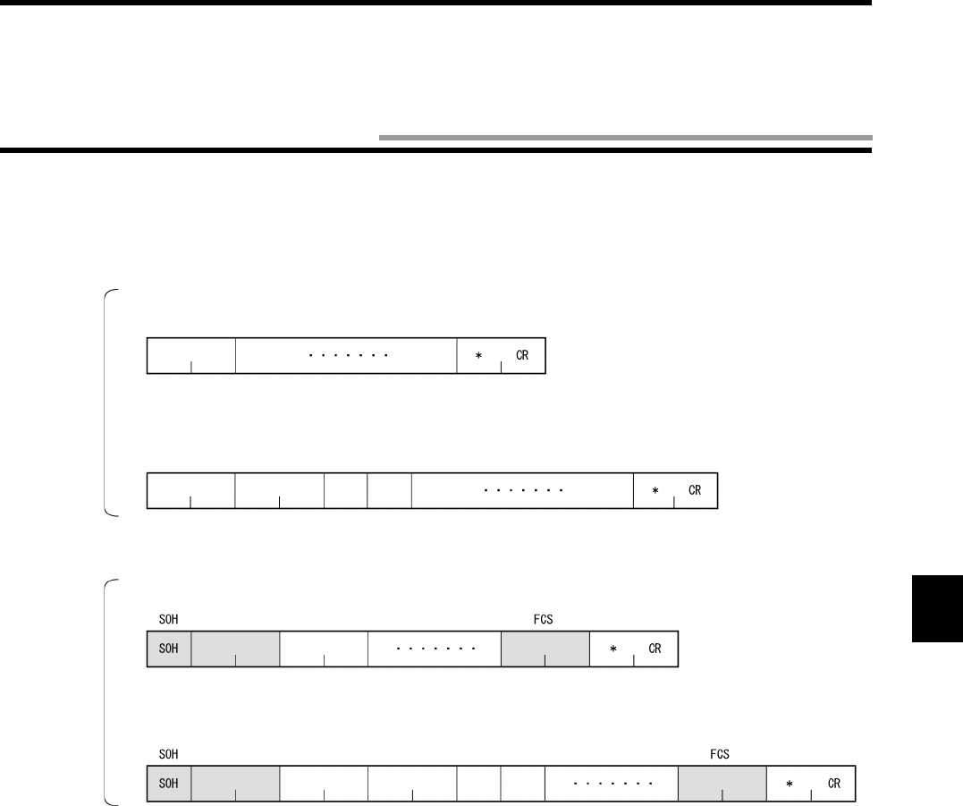
5-9
Communication commands to communicate with a tag are described here in this section. The commands are described assuming that
1:1 protocol is used. If 1:N protocol is used, follow the 1:N protocol format. (For details of protocol format, refer to "5-2 Command
Response Format".)
1:1 Protocol
Example of sent data
Example of received data
Command code Data Terminator
Te r mi n a t orCommand code Data
Termination code
Retransmis-
sion flag
Status
flag
1:N Protocol
Command codeNode No. Data Terminator
Command codeNode No. Data TerminatorTermination
Retransmis-
sion flag
Status
flag
Example of sent data
Example of received data
5-6 Communication Command
5-6 Communication Command
5-10
5-6-1 Read (RD)
Reads a data in a area specified by the first address and the number of bytes.
Example: Reading 8 bytes of data from the address 0000h
(Single trigger, hexadecimal code)
Sent data: RDSTH 1 0 0 0 0 0 8 * [CR]
Received data: RD 0 0 0 0 1 2 3 4 5 6 7 8 1 2 3 4 5 6 7 8 * [CR]
Communication designation Specifies how to communicate with a tag.
For details, refer to the communication designation list.
Data designation Specifies a type of transmitted code of read data at the response.
"A": ASCII code
"H": Hexadecimal code
Antenna designation Fixed to "1".
First address of read area Specifies the first address of area, where data is read from a tag, in four hexadecimal
digits.
Available designation range: 0000h to 007Fh.
Number of read bytes Specifies the number of bytes to be read in HEX code.
The number of bytes that can be read at a time is as follows:
-ASCII:256 bytes (256 characters)
-HEX:128 bytes (256 characters)
Available designation range: 01h to 80h.
Read data Data read from a tag. For the ASCII code, the number of characters is the number of read bytes.
For the hexadecimal code, the number of characters is the number of read bytes x 2.
Correct Usage
Specify the number of read bytes so that the sum of the number of read bytes and the first address of read area cannot
exceed the tag memory capacity (128 bytes).
Example: For the address 0010h, the range between 00h and 70h can be specified.
<Command>
Command
code
"RD"
Communication
designation
Data
desig-
nation
Antenna
desig-
nation
First address of read area Number of read
bytes
<Response>
Command
code
"RD"
Termination
code
"00"
Retrans-
mission
flag
Status
flag
Read data
Number of specified bytes
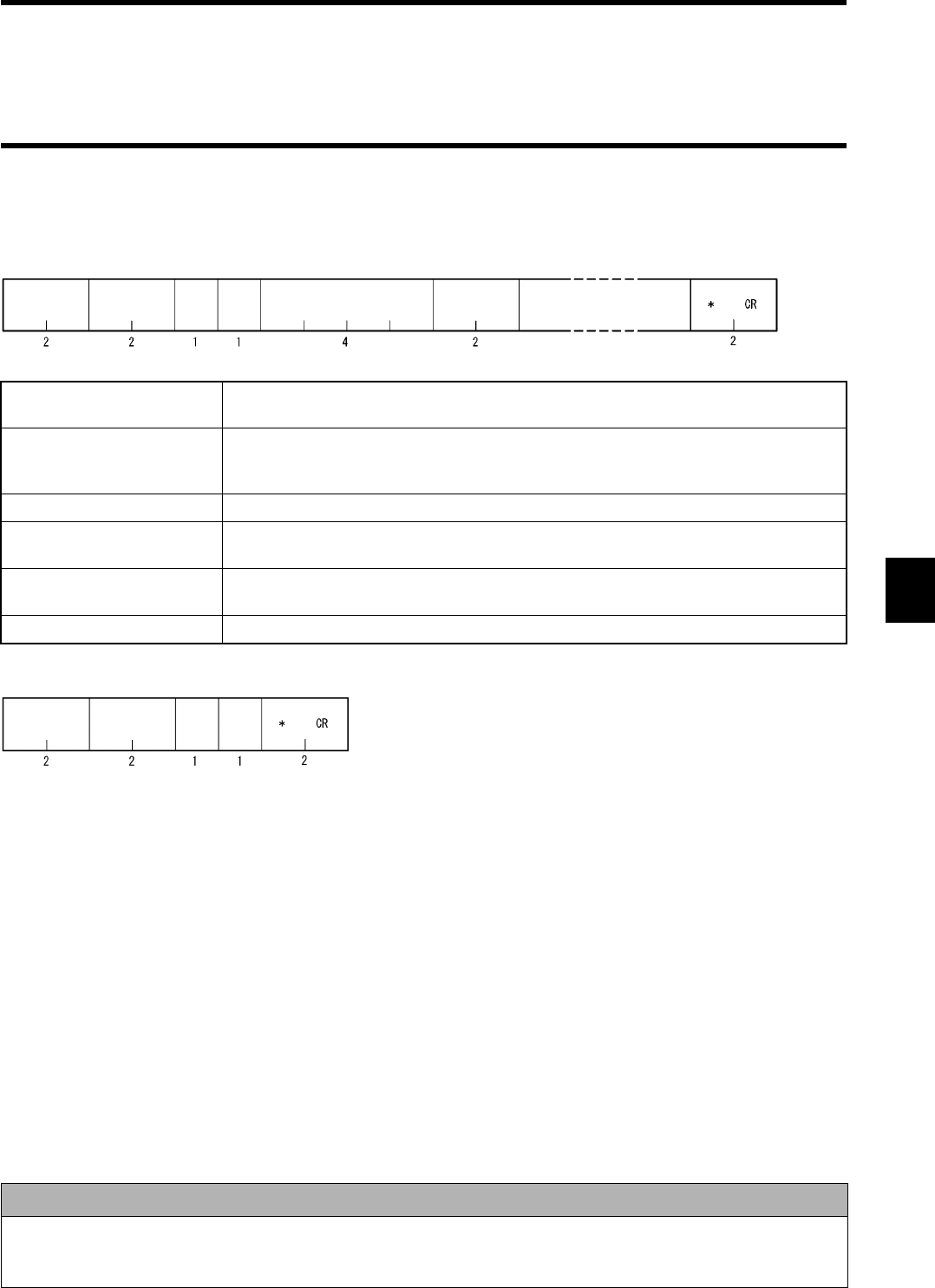
5-6 Communication Command
5-11
5-6-2 Write (WT)
Writes the specified bytes of data from the specified first address into a tag.
Example: Writing 4 bytes of data ("11223344") from the address 0010h
(Single trigger, hexadecimal code)
Sent data: WTSTH 1 0 0 1 0 0 4 1 1 2 2 3 3 4 4 * [CR]
Received data: WT 0 0 0 0 * [CR]
Communication designation Specifies how to communicate with a tag. For details, refer to the communication desig-
nation list.
Data designation Specifies a type of transmitted code of data written into a tag.
"A": ASCII code
"H": Hexadecimal code
Antenna designation Fixed to "1".
First address of written area Specifies the first address of area, where data is written into, in four hexadecimal digits.
Available designation range: 0000h to 007Fh.
Number of written bytes Specifies the number of bytes of data written into a tag in two hexadecimal digits.
Available designation range: 01h to 80h.
Written data Data written into a tag. For a hexadecimal code, two characters per byte.
Correct Usage
Specify the number of written bytes so that the sum of the number of written bytes and the first address of written area
cannot exceed the tag memory capacity (128 bytes).
Example: For the address 0010h, the range between 00h and 70h can be specified.
<Command>
Command
code
"WT"
Communication
designation
Data
desig-
nation
Antenna
desig-
nation
The first address of written area The number of
written bytes
Written data
Number of specified bytes
<Response>
Command
code
"WT"
Termination
code
"00"
Retrans-
mission
flag
Status
flag
5-6 Communication Command
5-12
5-6-3 Computation Write (CW)
Performs the computation of data in tag memory and computation data in a hexadecimal number and writes the result into the tag. If
overflow and underflow occurs in addition and subtraction, respectively, no data is written and "1" is returned to the status flag.
Example: Subtracting the computation data ("0002") from 2 bytes data ("0010") in the address 0001h and writing the result
(Single trigger, initial value "0010")
Sent data: CWSTS 1 0 0 0 1 0 2 0 0 0 2 * [CR]
Received data: CW 0 0 0 0 0 0 0 E * [CR]
Communication designation Specifies how to communicate with a tag. For details, refer to the communication desig-
nation list.
Process designation Specifies how to compute.
"A": Hexadecimal addition
"S": Hexadecimal subtraction
Antenna designation Fixed to "1".
First address of computation
area
Specifies the first address of area, where data is computed, in four hexadecimal digits.
Available designation range: 0000h to 007Fh.
Number of addition area
bytes
Specifies the number of bytes of area, where data is computed, in two hexadecimal dig-
its.
Available designation range: 01h to 04h.
Computation data Specifies a numerical value to be computed in a hexadecimal number.
Result data Returns a calculation result data written into the tag. If overflow and underflow occurs in addition
and subtraction, respectively, the result data is a data before the calculation. In this case, the sta-
tus flag is "1".
Correct Usage
This command performs the hexadecimal computation. So, you must specify all the data in a hexadecimal code. More-
over, specify an addition area within one page. Otherwise, a command error occurs.
<Command>
Command
code
"CW"
Communication
designation
Process
designa-
tion
Antenna
designa-
tion
The first address of computation
area
The number of
computation
area bytes
Computation data
Number of specified bytes
<Response>
Command
code
"CW"
Termination
code
"00"
Retrans-
mission
flag
Status
flag
Result data
Number of specified bytes
5-6 Communication Command
5-13
5-6-4 Data Fill (DF)
Write 1 or 2 bytes of the same data into an area specified by the first address and the last address of tag memory. Written data is speci-
fied by a hexadecimal code.
Example: Writing a fixed data ("00FF") from the address 0000h to 007Fh
(Single trigger, writing 2 bytes)
Sent data: DFSTW 1 0 0 0 0 0 0 7 F 0 0 F F * [CR]
Received data: DF 0 0 0 0 * [CR]
Communication designation Specifies how to communicate with a tag. For details, refer to the communication desig-
nation list.
Data designation Specifies a unit of written data.
"B": Byte
"W": Word (2 bytes)
Antenna designation Fixed to "1".
First address of written area Specifies the address to write a data into a tag in four hexadecimal digits.
Available designation range: 0000h to 007Fh.
Last address of written area Specifies the last address to write a data into a tag in four hexadecimal digits.
Available designation range: 0000h to 007Fh.
Written data Data written into a tag. Specify 1 or 2 bytes of hexadecimal code.
Correct Usage
When you write a fixed data into a specified area, this command can reduce the traffic to a host device and, therefore,
the system can be operated fast by this command.
<Command>
Command
code
"DF"
Communication
designation
Data
desig-
nation
Antenna
designa-
tion
The first address of written area Written data
1/2 byte
The last address of written area
<Response>
Command
code
"DF"
Termination
code
"00"
Retrans-
mission
flag
Status
flag

5-6 Communication Command
5-14
5-6-5 Memory Check (MD)
Executes the generating polynomial X16 + X12 + X5 + 1 in an area per check block specified by a user and verifies with a check code
added in the check block.
Example: Example of address: Adding a check code to 4 bytes of data from the address 0010h
(Single trigger)
Sent data: MDSTK 1 0 0 1 0 0 6 * [CR]
Received data: DF 0 0 0 0 * [CR]
* 2 Bytes of data are added to 4 bytes of data. So, the number of specified bytes is 6.
Communication designation Specifies how to communicate with a tag. For details, refer to the communication desig-
nation list.
Process designation Specifies a type of check process.
"K": Check code calculation
"C": Check code verification
Antenna designation Fixed to "1".
First address of check block Specifies the first address of check block in four hexadecimal digits.
Available designation range: 0000h to 007Dh.
Number of bytes of check
block
Specifies the number of bytes of check block in two hexadecimal digits.
Available designation range: 03h to 80h.
Status flag Shows the verification result of check code.
"0": The verification result is normal.
"1": The verification result is abnormal.
Correct Usage
Do not write necessary information into the last 2 bytes of an area because 2 bytes are used for a record of check code.
For details, refer to "4-5 Memory Check Function".
<Command>
Command
code
"MD"
Communication
designation
Process
designa-
tion
Antenna
designa-
tion
The first address of check block The number of
bytes of check
block
<Response>
Command
code
"MD"
Termination
code
"00"
Retrans-
mission
flag
Status
flag
5-6 Communication Command
5-15
5-6-6 Tag Function Designation (TF)
Sets/cancels Write Protect etc. to a tag.
Example: Setting Write Protect function of the addresses 0010h to 001Fh to a tag
(Single trigger)
Setting protect area information
Sent data: WTSTH 1 0 0 0 0 0 4 0 0 1 0 0 0 1 F * [CR]
Received data: WT 0000*[CR]
Setting protect function
Sent data: TFSTP 1 * [CR]
Received data: TF 0 0 0 0 * [CR]
Communication designation Specifies how to communicate with a tag. For details, refer to the communication desig-
nation list.
Process designation Sets/cancels a function.
"P": Sets Protect
"R": Cancels
Antenna designation Fixed to "1".
Correct Usage
For details of Write Protect, refer to "4-6 Write Protect Function".
<Command>
Command
code
"TF"
Communication
designation
Process
designa-
tion
Antenna
designa-
tion
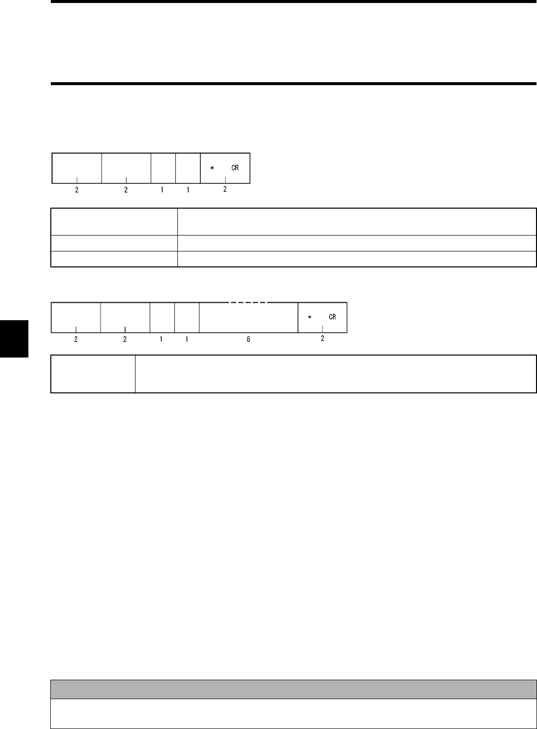
5-6 Communication Command
5-16
5-6-7 ID Read (ID)
Reads a user ID of tag.
Example:Reading user ID of tag
(Single trigger, user ID "1 2 3 4 5 6 7 8")
Sent data: IDSTH1*[CR]
Received data: ID 0 0 0 0 1 2 3 4 5 6 7 8 * [CR]
Communication designation Specifies how to communicate with a tag. For details, refer to the communication desig-
nation list. The communication designation "st" only is unavailable.
Data designation Fixed to "H" (hexadecimal code).
Antenna designation Fixed to "1".
Read data User ID data read out of a tag.
"00000000" to "3FFFFFFF"
High order 2 bits are fixed to "0" because of system bit.
Correct Usage
Every tag stores its own code. If it needs to be checked only whether there is a tag or not, communication can be done
very fast by this command.
<Command>
Command
code
"ID"
Communication
designation
Data
desig-
nation
Antenna
designa-
tion
<Response>
Command
code
"ID"
Termination
code
Retrans-
mission
flag
Status
flag
Read data
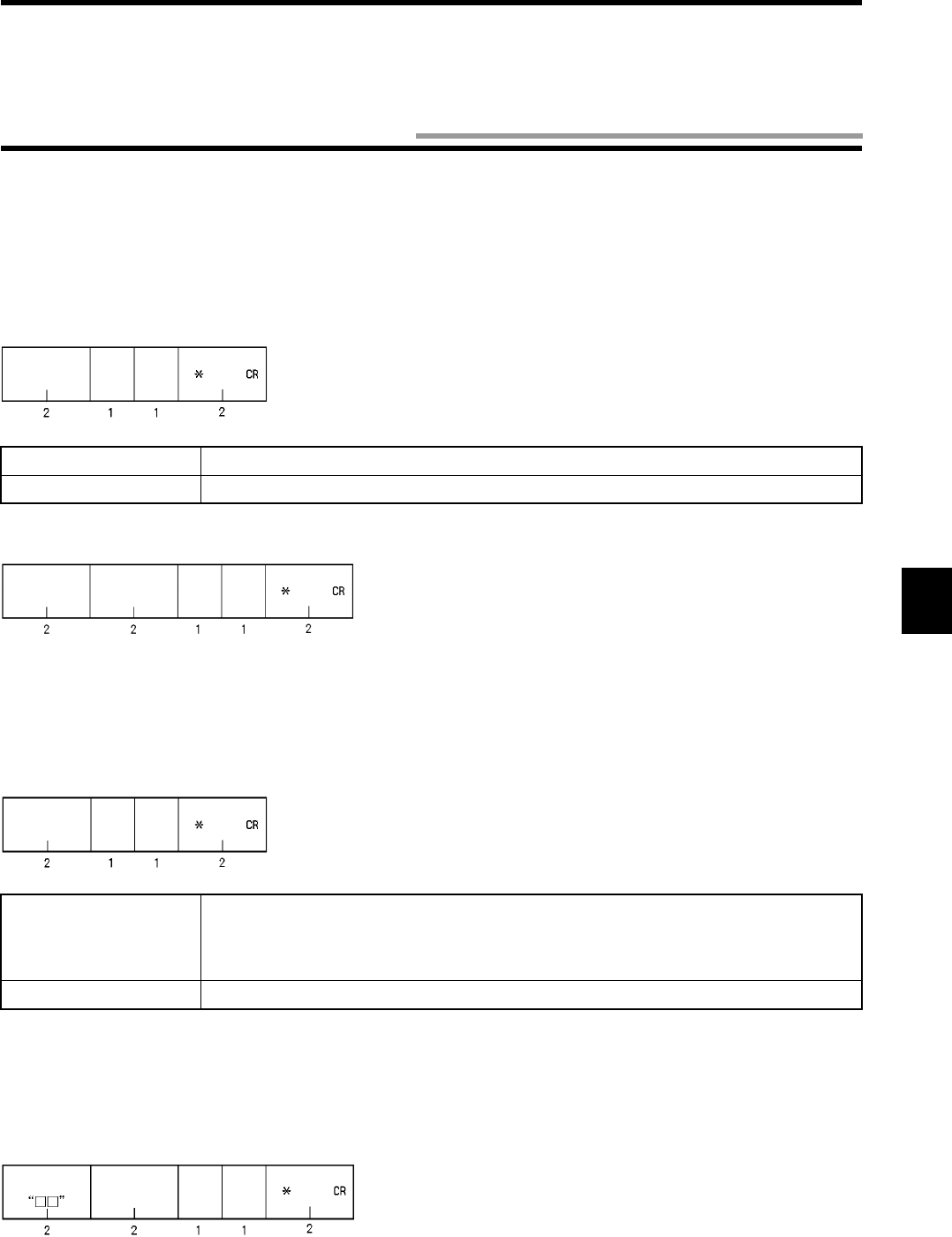
5-17
The communication subcommand is used in combination with a communication command. Any communication to a tag cannot be done
by the subcommand alone.
5-7-1 Command Processing Abort (AA)
Aborts a command process in execution and returns to a state of waiting for a command. This can be executed when any command
other than the communication designation "ST" is in process.
When a command process has been aborted after a tag is detected, the status flag becomes "2".
5-7-2 Polling Query (PC)
Inquires the result of communication with a tag during polling.
<Response>
(1) Received after the communication with a tag is ended.
Response according to a type of command executed specified by the communication designation of polling.
(2) Received before the communication is ended.
The command code is the same as one when polling is executed.
Process designation Fixed to "0".
Antenna designation Fixed to "1".
Process designation Specifies a type of process when the result has been returned after the communication
ends.
"E": Process ended.
"C": Executes the same command again.
Antenna designation Fixed to "1".
<Command>
Command
code
"AA"
Process
designa-
tion
Antenna
designa-
tion
<Response>
Command
code
"AA"
Termination
code
Retrans-
mission
flag
Status
flag
<Command>
Command
code
"PC"
Process
designa-
tion
Antenna
designa-
tion
<Response>
Command
code
Termination
code
"74"
Retrans-
mission
flag
Warning
flag
5-7 Communication Subcommand
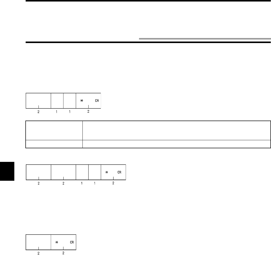
5-18
The controller control commands have no direct relation to the communication to a tag, but those commands specify the communication
conditions, controller operation mode, Self-Execution conditions, etc.
5-8-1 Operation Mode Change (MO)
Changes a controller operation mode.
5-8-2 Data Retransmission (RR)
Requests to send again the last response from the controller.
<Response>
Returns the response data returned last. In this case, the retransmission flag becomes "1".
Process designation Specifies a controller operation mode.
"S": Self-Execution mode
"C": Command Execution mode
Execution designation Fixed to "0".
<Command>
Command
code
"MO"
Process
designa-
tion
Execu-
tion des-
ignation
<Response>
Command
code
"MO"
Termination
code
Retrans-
mission
flag
Status
flag
<Command>
Command
code
"RR"
5-8 Controller Control Command
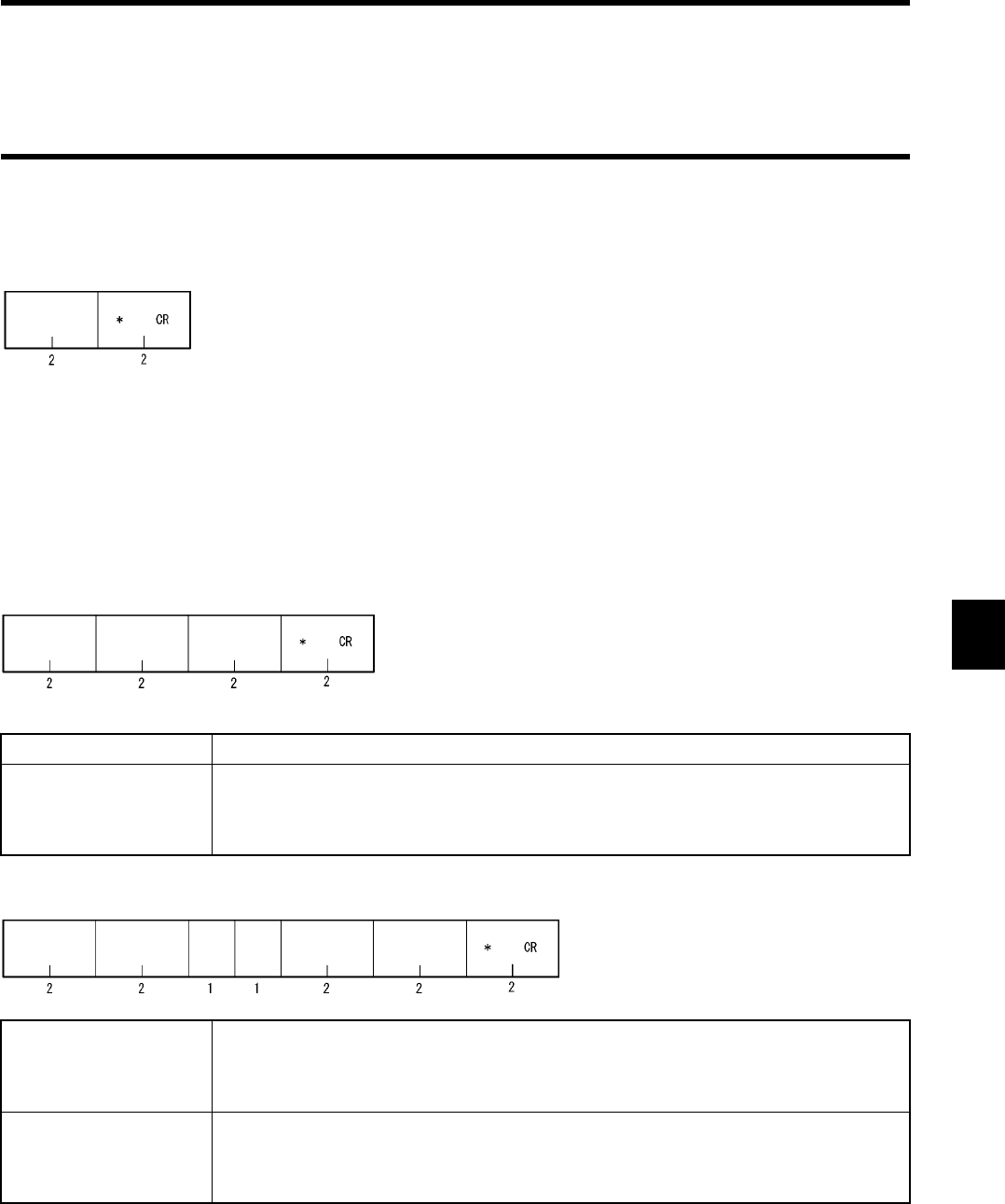
5-8 Controller Control Command
5-19
5-8-3 Reset (XZ)
Aborts all the controller processes and performs "Power ON" initial process. There is no response.
<Response>
Nil
5-8-4 Controller Control (CC)
Changes or obtains the state of external I/O of controller.
Process code Fixed to "00" (I/O control).
External output informa-
tion
Specifies the output of external output 1 and external output 2.
"0": No change
"1": Turned OFF forcibly.
"2": Turned ON forcibly.
External input informa-
tion
Returns the signal status when a command of external input has been received. (The sec-
ond character is always "0".)
"0": "OFF"
"1": "ON"
External output informa-
tion
Returns the signal status when a command of external output 1 and external output 2 has
been received.
"0": "OFF"
"1": "ON"
<Command>
Command
code
"XZ"
<Command>
Command
code
"CC"
Process code External out-
put information
<Response>
Command
code
"CC"
Termination
code
Retrans-
mission
flag
Status
flag
External input
information
External output
information
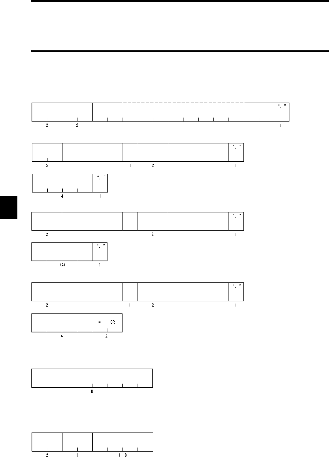
5-8 Controller Control Command
5-20
5-8-5 Operation Condition Setting (SE)
Specifies operating conditions in the Self-Execution mode.
* There are the following three patterns in the comparison parameter section.
The condition is regarded as ER (Communication NG) in the communication judgment:
The condition is regarded as anything other than ER in the communication judgment:
No parameter
The condition is data judgment:
<Command>
(1) Process command
Command
code
"SE"
Process code Example of execution command
(2) OUT1 output
Condition (A) Comparison parameter* Opera-
tor
Condition (B) Comparison parameter*
Output parameter
(3) OUT2 output
Condition (A) Comparison parameter* Opera-
tor
Condition (B) Comparison parameter*
Output parameter
(4) RS-232C output
Condition (A) Comparison parameter* Opera-
tor
Condition (B) Comparison parameter*
Output parameter
Error code
Comparison data
Number of bytes
of data
Data offset
to
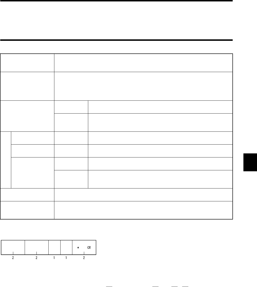
5-8 Controller Control Command
5-21
* The communication judgment condition DS performs the process only when the status flag becomes "1" ("CW" and "MD" only).
Even if no condition is specified (e.g., OUT1/2 is "1 condition judgment", there is no output to "OUT2 RS-232C" etc.), send an uncon-
ditional symbol ("X") according to the format (underlined in the data string below). If this symbol is not sent, a format error (14) occurs.
Sent data string: "SE00RDRAH1001010, = 080400000001 + XX, 0500, ER00000000 + XX, 0000, XX + XX, 0000"
Process code Specifies an operation to be executed in the operating condition.
"00": Setting
"10": Read
Example of execution
command
Specifies a command to be executed according to the following conditions.
Condition 1: A command can be specified by a communication command only.
Condition 2: The communication designation is "RA" and "RI" only.
Condition 3: The number of written bytes is a maximum of 8 bytes (for both of ASCII and
hexadecimal).
Condition
(A) (B)
Communica-
tion judgment
"OK": Communication OK. "ER": Communication NG. "DS": Data status.
"AL": Always. "xx": Nil.
Data judgment "= =": Judgment data matched. "! =": Judgment data unmatched.
"> =": Judgment data or more. "< =": Judgment data or less.
The data judgment can be used by an execution command "RD" or "CW".
Data offset
(A) (B)
Condition is
data judgment
Specifies an offset value of area used for judgment in read data string.
Available designation range is between 00h and 7Fh.
Number of bytes of
data (A) (B)
Condition is
data judgment
Specifies the number of bytes which performs judgment.Available desig-
nation range is between 01h and 04h.
Comparison data
(A) (B)
Condition is
data judgment
Specifies a comparison data for data judgment.
Condition is
"ER" judgment
Error code designation. If "00000000" is specified, process is executed
when any error occurs.
Example: "707A0000" Communication error and address error.
Operator Operator for the condition A and condition B.
"&": AND, "+": OR
Output parameter Specifies the output ON time in millisecond assuming that a process method is output.
1 to 9999 millisecond. Continued to the next judgment (0000 is specified).
Fixed to "0000" in the RS-232C output part.
<Response>
Command
code
"SE"
Termination
code
"00"
Retrans-
mission
flag
Status
flag
Comparison parameter
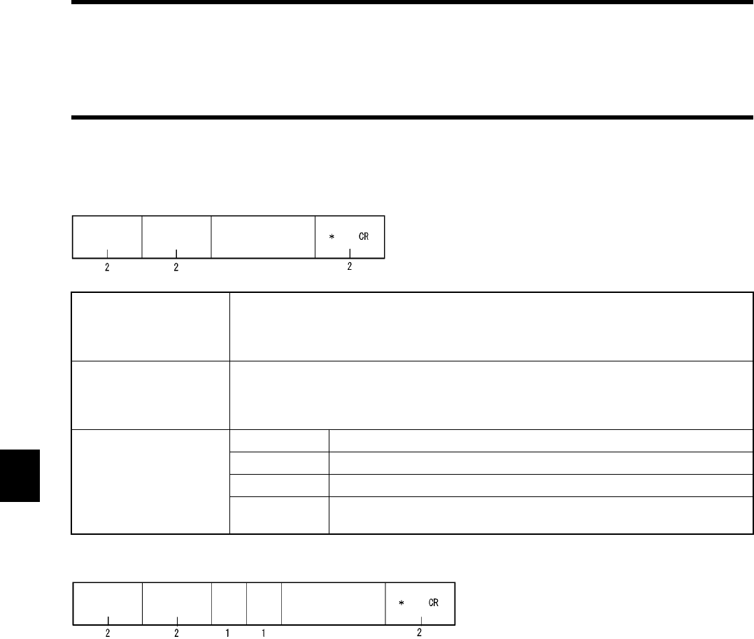
5-8 Controller Control Command
5-22
5-8-6 Parameter Setting (SP)
Operates the parameters used in the controller from a host device.
Process code
(High order digit)
Specifies a type of process to parameter.
"0": Change
"1": Read
"9": Initialize (set to a default value)
Process code
(Low order digit)
Specifies a type of parameter.
"1": Character interval monitoring time
"2": Response Ready time
"3": Communication restriction time setting
Parameter data
(only when changing)
Data No. Available value
"1" Specifies four decimal digits. 0 to 9999 (ms)
"2" Specifies two decimal digits. 0 to 99 (ms)
"3" Specifies two decimal digits. 01 to 99 (x 10 ms). For "00", nothing is
specified.
<Command>
Command code
"SP"
Process code Parameter data
(only when changing)
<Response>
Command
code
"SP"
Termination
code
Retrans-
mission
flag
Status
flag
Parameter data
(only when changing)
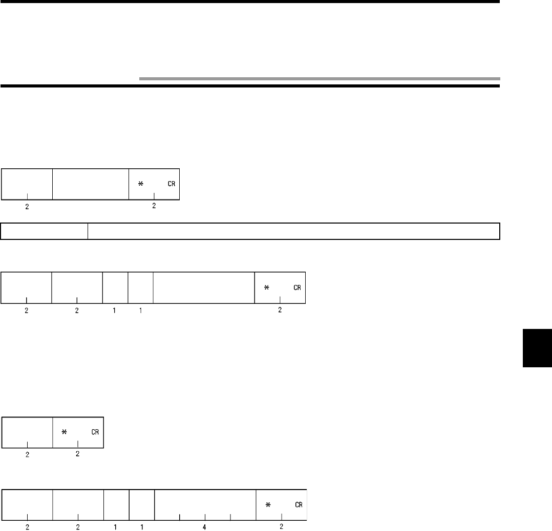
5-23
5-9-1 Test (TS)
Makes a response directly to a message sent by a host device. This command is used for a communication test between the host device
and ID controller.
5-9-2 Version Information (VS)
Reads a version of software of the controller.
Message data Any character string to execute a test communication.
<
C
ommand>
Command code
"TS"
Message data
<Response>
Command
code
"TS"
Termination
code
Retrans-
mission
flag
Status
flag
Message data
<Command>
Command code
"VS"
<Response>
Command
code
"VS"
Termination
code
Retrans-
mission
flag
Status
flag
Version of software
5-9 Host Command

5-24
The meanings of termination code of response are described below.
Type
Termination Code
Name Description
Normal end "00" Normal end Command execution has ended correctly. A command
was executed correctly when polling process is speci-
fied.
Host commu-
nication
error
"10" Parity error A parity error has occurred in any character of com-
mand.
"11" Framing error A framing error has occurred in any character of com-
mand.
"12" Overrun error An overrun error has occurred in any character of com-
mand.
"13" FCS error FCS of received command is invalid.
"14" Format error A command format is incorrect. Character interval has
exceeded a preset time.
"15" Execution status error Communication designation is SI/RI/PI when input set-
ting is RESET. The "MO" command was executed
when no operating condition is registered.
"18" Frame length error A command string more than 300 characters was
received.
Tag communi-
cation error
"70" Communication error An error has occurred during the communication with a
tag and the communication cannot be completed cor-
rectly.
"71" Verification error A correct data cannot be written into a tag (only when
verification is enabled).
"72" No-tag error There is no tag in a communication area of antenna
when a trigger system command is executed. In a com-
mand which performed communication designation of
"st", there is no tag, which communicated immediately
before, in a communication area of antenna. The
antenna is not connected.
"74" Outstanding tag error In polling query, a communication process has not yet
been completed.
"7A" Address designation
error
Designation of process address is unsuitable and the
execution is impossible.
"7D" Write protect error Something was written into a write-protected page.
"7E" ID system error (1) A tag cannot execute a command process.
"7F" ID system error (2) An inapplicable tag was used.
System error "7C" Antenna section error No communication can be executed due to antenna
trouble.
"9A" EEPROM error An error in writing into/reading from nonvolatile memory
in the controller (the SP/SE command). The "MO" com-
mand was executed under invalid operating condition.
5-10 Termination Code List

5-25
Example of BASIC program
1:1 Protocol
100 ’***** V670-CD1D SAMPLE PROGRAM *****
110 CLS
120 OPEN “COM:E73NN” AS #1 ’Opens a RS-232C port.
130 ’
140 ’***** MAIN LOOP ****
150 *LOOP
160 LINE INPUT “Input TX Data : “, ITD$ ’Inputs a command data.
170 TXD$=ITD$+”*”+CHR$(13) ’Sets a data string to be sent.
180 PRINT “[TX] : “;ITD$ ’Displays a command data.
190 PRINT #1,TXD$; ’Sends a data string.
200 GOSUB *RECEIVE ’Receives a data string.
210 PRINT “[RX] : “;REC$ ’Displays a response data.
220 GOTO *LOOP
230 ’
240 ’***** RECEIVE DATA *****
250 *RECEIVE
260 RXD$=” “
270 WHILE (LOC(#1)=0):WEND ’Checks a receiving buffer.
280 WHILE (INSTR(RXD$,”*”+CHR$(13))=0) ’Checks a termination code.
290 RXD$=RXD$+INPUT$(1,#1) ’Reads a received data.
300 WEND
310 REC$=LEFT$(RXD$,LEN(RXD$)-2) ’Extracts a response data.
320 RETRUN
330 ’
340 END
5-11 Example of Communication Program

5-11 Example of Communication Program
5-26
1:n Protocol
100 ’***** V670-CD1D SAMPLE PROGRAM2 *****
110 CLS
120 OPEN “COM:E73NN” AS #1 ’Opens a RS-232C port.
130 ’
140 ’***** MAIN LOOP ****
150 *LOOP
160 LINE INPUT “Input TX Data : “, ITD$ ’Inputs a command data.
170 IP$=”00”+ITD$:GOSUB *FCS ’Calculates FCS.
180 TXD$=CHR$(1)+IP$+OP$+”*”+CHR$(13) ’Sets a data string to be sent.
190 PRINT “[TX] : ”;ITD$ ’Displays a command data.
200 PRINT #1,TXD$; ’Sends a data string.
210 GOSUB *RECEIVE ’Receives a data string.
220 PRINT “[RX] : “;REC$ ’Displays a response data.
230 GOTO *LOOP
240 ’
250 ’***** RECEIVE DATA *****
260 *RECEIVE
270 RXD$=” “
280 WHILE (LOC(#1)=0):WEND
290 WHILE (INSTR(RXD$,”*”+CHR$(13))=0)
300 RXD$=RXD$+INPUT$(1,#1)
310 WEND
320 IP$=MID$(RXD$,2,LEN(RXD$)-5):GOSUB *FCS ’Calculates FCS
330 REC$=MID$(RXD$,4,LEN(RXD$)-7)
340 FCS$=MID$(RXD$,LEN(RXD$)-3,2):GOSUB *CHK.FCS ’Checks FCS
350 RETRUN
360 ’
370 ‘***** CALCULATE FCS *****
380 *FCS
390 K=0
400 FOR I=1 TO LEN(IP$)
410 TMP$=MID$(IP$,I,1)
420 K=K XOR ASC(TMP$)
430 NEXT I
440 OP$=HEX$(K)
450 RETURN
460 ‘
470 ‘***** CHECK FCS *****
480 *CHK.FCS
490 IF FCS$<>OP$ THEN REC$=”FCS ERR!!”
500 RETURN
510 ’
520 END

6-1
In the Self-Execution mode, by executing automatically the operating conditions (communication command, judgment condition, out-
put condition, etc.) registered in the controller, the communication and peripheral devices can be controlled without control from a host
device.
In the Self-Execution mode, the following conditions can be specified.
* For a format and any other details, refer to "5-8-5 Operation Condition Setting (SE)".
* There is a limited number of commands that can be used in self-execution mode. For details, refer to Chapter 5-4, "Command List."
Item Condition Remarks
Execution com-
mand
Communication command. For the communication command, refer to "5-4 Command
List".
Communication
mode
RA, RI. Continuous operation is required in the Self-Execution mode.
So, a repeat system command only can be specified.
Output Signal output: OUT1/2.
Data output: RS-232C.
In the signal output, output time can be specified.
Data output is a response of execution command.
Number of judg-
ments
Two judgments per output. One judgment also can be specified.
Judgment condi-
tions
• Judgment in communication
result
• Comparison of data of
response
(matched, unmatched, large or
small).
For data comparison, an area to be compared can be speci-
fied. (1 to 4 bytes)
Chapter 6 How to Use Self-Execution Mode
6-1 Available Conditions

6-2
Procedure to use the Self-Execution mode is described below.
(1) Connect a host interface, power supply and antenna.
(2) Turn on the power supply.
(3) Check a host communication with a test command.
(4) Register an operating condition with the SE (Operation Condition Setting) command.
(5) Enter the Self-Execution mode through the dip switch (turn ON SW 3-2) or with the MO (Operation Mode Change) command.
If you enters the Self-Execution mode through the dip switch, turn OFF the power supply once, turn on the power supply again and
check the operation.
-- Then, the antenna starts communicating. --
(6) Check an operation by using an applicable tag to check the operating condition.
Here, you can use the Self-Execution mode.
If you want to cancel the Self-Execution mode due to any reason, use the MO (Operation Mode Change) command.
6-2 Setting Procedure

6-3
An example of setting to execute the following items is described.
Communication process : Reads 16 bytes from the address 10h in a hexadecimal number in an automatic operation.
Judgment, OUT1 output : 4 Bytes of data from the address 18 is "00000001" and turning ON for 0.5 seconds.
Judgment, OUT2 output : ON at an error. (Time is not monitored.)
Judgment, RS-232C output: No output.
•Sent command string
"SE00RDRAH1001010, = = 080400000001 + XX, 0500, ER00000000 + XX, 0000, XX + XX, 0000"
•Description of sent command string
SE00RDRAH1001010 ← Execution command
Read 16 bytes from the address 10h.
==080400000001+XX, 0500, ← Specifies a condition of OUT1 output.
Output time (0.5 seconds).
No condition (B).
Condition (A) is judged as matched.
ER00000000+XX, 0000, ← Specifies a condition of OUT2 output.
ON (unlimited)
No condition (B).
Condition (A) is judged as unmatched. (All the error codes)
XX+XX, 0000 ← Specifies a condition of RS-232C output.
Fixed data.
No condition (B).
No condition (A).
6-3 Example of Setting

6-4
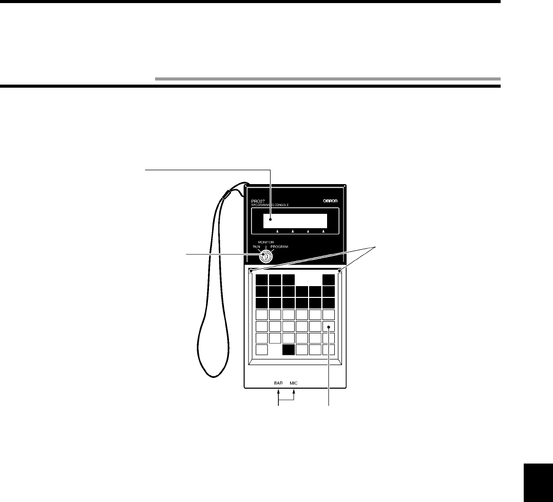
7-1
By using a Programming Console, the controller model V670-CD1D-V1 can check the communication with a tag at the system startup,
read/write a data of tag, check the controller setting and read the details of error. We recommend you to use our Programming Console
model C200H-PRO27 (unbundled). To connect the Programming Console to the controller, the cable model V700-P10 (unbundled) is
required.
LCD Display
Used to show a program
or as a monitor.
Mode Change Switch
Specifies a mode.
Key Sheet Slit
Keypad
Cassette
Jack
(not used)
Chapter 7 How to Use Programming Console
7-1 Component Name
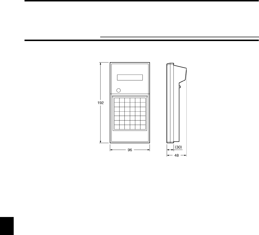
7-2
(Unit: mm)
7-2 Outside Dimension
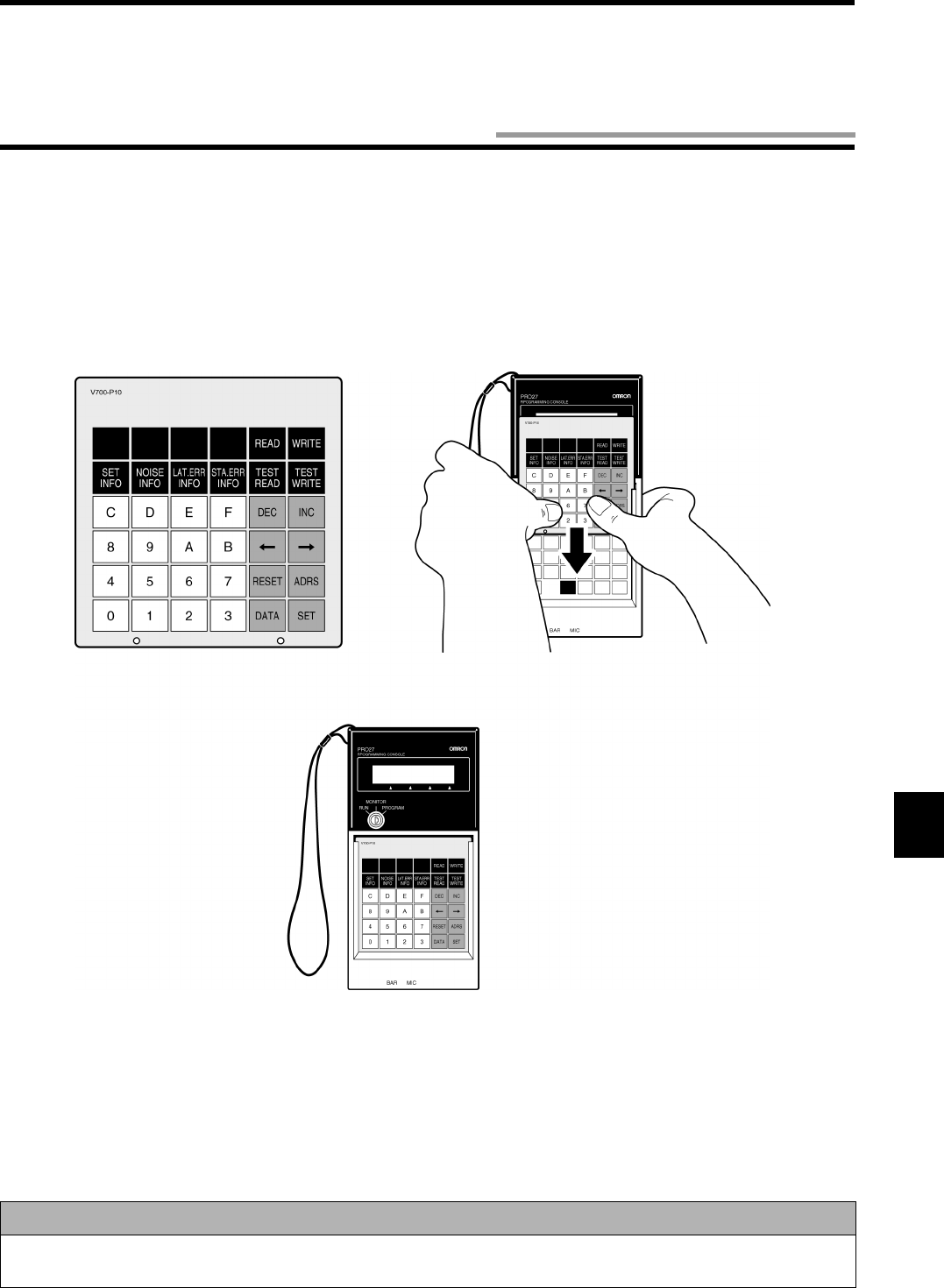
7-3
To connect the programming console to the controller, the cable model V700-P10 (unbundled) is required. A key sheet comes with the
cable model V700-P10.
7-3-1 Inserting Key Sheet
As shown below, insert the dedicated key sheet into the slit at the top of programming console. Insert the key sheet pressing it with your
fingers softly until the key sheet has been held completely in place.
Correct Usage
Insert the key sheet correctly as shown above. Otherwise, the keypad of the programming console may not function
properly.
7-3 Connection of Programming Console
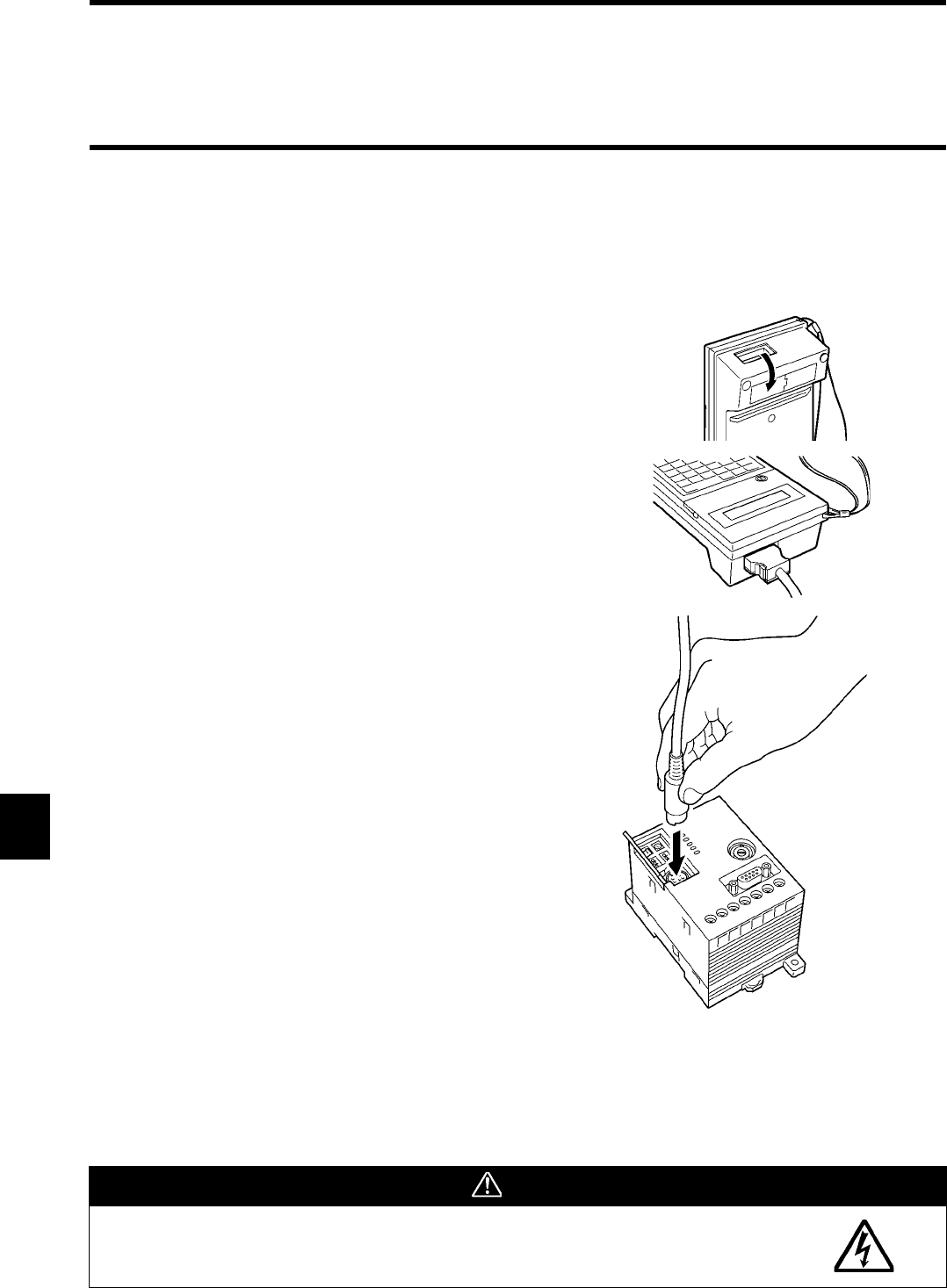
7-3 Connection of Programming Console
7-4
7-3-2 Connecting Cable
Connect the programming console with the dedicated cable model V700-P10. A round connector and square connector come with the
cable. Use the round connector and square connector to the controller, and the programming console respectively.
A connector always can be plugged into and unplugged from the programming console when the power supply turns on.
(1) Remove the connector cover at top of the reverse side or at the
reverse side. Keep the removed panel as shown in the figure.
(2) Insert the square connector of the connecting cable completely
until a lock lever clicks to fix it.
(3) Open a cover at the front panel of the controller.
(4) The round connector of the connecting cable is marked with an
arrow. Insert the connector with the arrow up into the program-
ming console connector of the controller completely. This connec-
tor is not equipped with a lock.
Caution
When you plug or unplug the connector into the programming console when the power supply
turns on, take care not to touch the controller wire. Otherwise, you may get an electric shock.
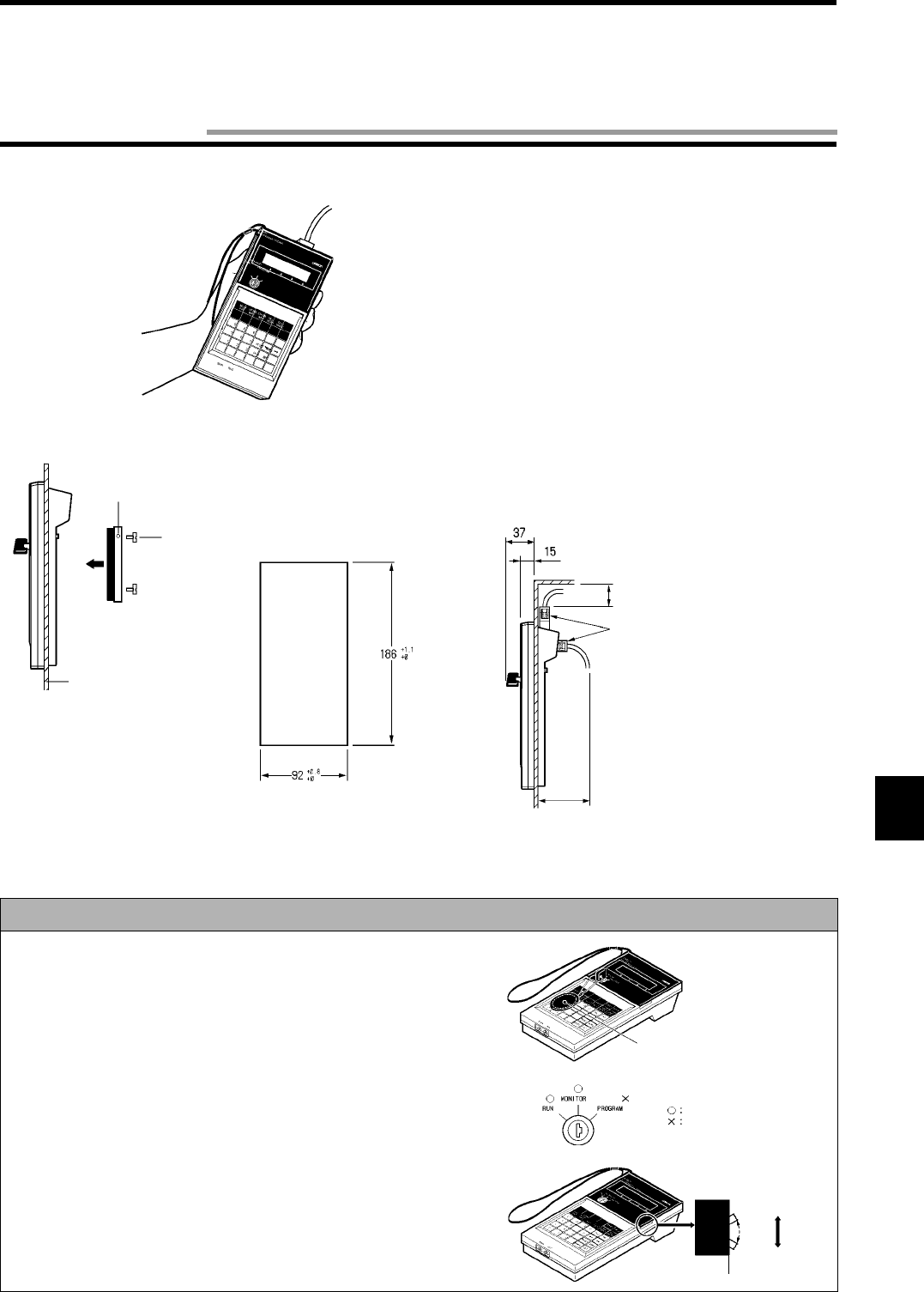
7-5
•Holding in your hand
•Panel installation
To install a panel, use a mounting bracket Type C200H-ATT01 (unbundled).
(Unit: mm) When you install the panel, take the cable height into consideration.
When you use this unit in a control panel etc., keep the ambient temperature within 0 and 45°C.
Correct Usage
• Do not attach a key holder etc. to the mode change key switch. Oth-
erwise, it becomes hard to operate the key pad.
• You can pull out the mode change key when it is positioned at RUN
or MONITOR. You cannot pull of the mode change key, when it is
positioned at PROGRAM.
• In the V670 Series, the PROGRAM mode is not used. Do not posi-
tion the key at PROGRAM when you use the V670 Series.
• To reduce the buzzer sound when you press the key pad, set the
lever at the side face of the programming console to an upper posi-
tion.
• When you disconnect the connecting cable from the programming
console, nip the levers at the both sides of the connector and then
pull out it.
Mounting bracket
Two screws
Applicable panel thickness
11.0 to 3.2
Mounting hole dimension
Standard panel cut is as fol-
lows (based on DIN43700):
Approximately 50 mm
Use either connector.
Approximately 70 mm
If you attach a key holder, it becomes
hard to operate the key pad.
You can pull out the key.
You cannot pull out the key.
Buzzer sound small
Buzzer sound large
7-4 How to Use
7-6
By using a programming console, the controller model V670-CD1D-V1 can check the communication with a tag at the system startup,
read/write a data of tag, check the controller setting and read the details of error.
7-5-1 Programming Console Function List
(1) MONITOR Mode
• Display of Setting
Displays every item of controller setting (DIP-SW).
• Reading/Writing
Reads/Writes the content of a tag put in front of an antenna.
• Communication Test
Used to check the communication or communication area when a tag moves.
• Latest Error Information
Displays a maximum of 30 items of error information in order of occurrence.
• Statistic Error Information
According to the error code, displays the number of errors occurred after the controller started the operation.
(2) RUN Mode
• Display of Setting
Displays every item of controller setting (DIP-SW).
• Execution Status Monitor
Displays any command, termination code, etc., which the controller received, in real time.
(3) PROGRAM Mode
This mode is unavailable in this controller.
MONITOR Mode Display of Setting
Reading/Writing
Communication
Latest Error Information
Statistic Error Information
Display of Setting
Execution Status Monitor
RUN Mode
PROGRAM Mode
Read
Write
Execution of Test Read
Execution of Test Write
7-5 Functions
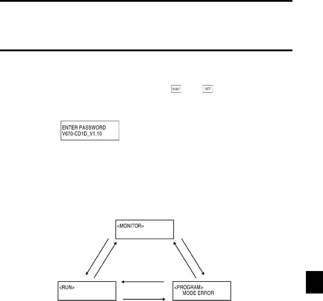
7-5 Functions
7-7
7-5-2 How to Operate
7-5-2-1 Password Input Screen
When the programming console is connected, the screen below appears. Press and then . An initial status of the mode is dis-
played according to key switch setting.
If you enter the password when the key switch is set to the MONITOR mode, all the operations are aborted even if the controller works.
Please note that the screen is ready to accept the execution of operation in the MONITOR mode then.
7-5-2-2 Changing Operation Mode
The controller operation mode is switched by changing the key switch of the programming console.
• MONITOR Mode
Communication with a tag can be executed by using the programming console in the MONITOR mode. Any command cannot be
controlled from a host device.
• RUN Mode
The controller setting and execution status can be displayed in the RUN mode. Any other functions cannot be used.
• PROGRAM Mode
This mode is unavailable in this controller.
Set the key switch to RUN. Set the key switch to
MONITOR. Set the key switch to PROGRAM.
Set the key switch to RUN.
Set the key switch to PROGRAM.
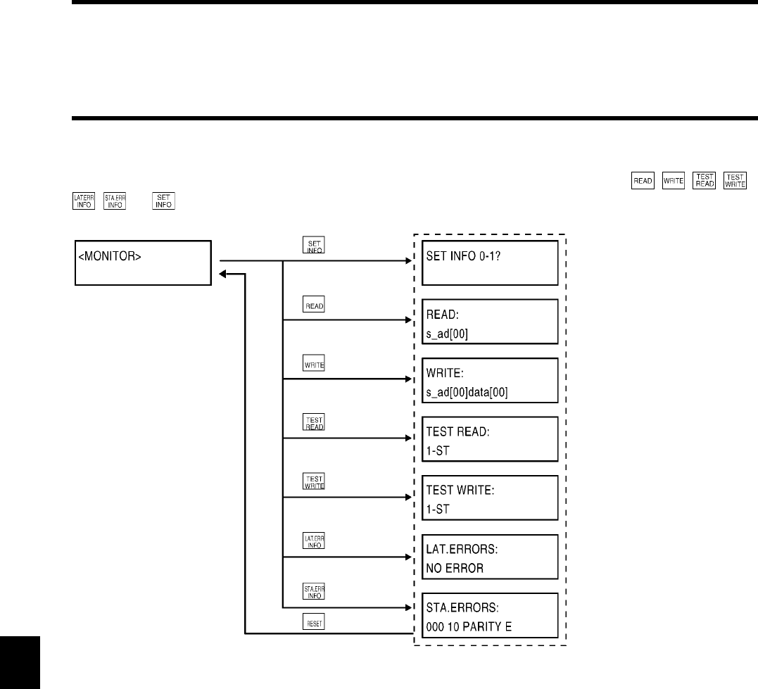
7-5 Functions
7-8
7-5-2-3 Accepting Key in Initial Screen of Monitor Mode
When the key switch is set to MONITOR, an initial screen of MONITOR mode is appears. In this screen, the , , , ,
, and keys only can be accepted.
Shows the display information
selection screen.
Shows the READ initial selection
screen.
Shows the WRITE initial selection
screen.
Shows the TEST READ initial
selection screen.
Shows the TEST WRITE initial
selection screen.
Shows the latest error information
screen.
Shows the statistic error information
screen.
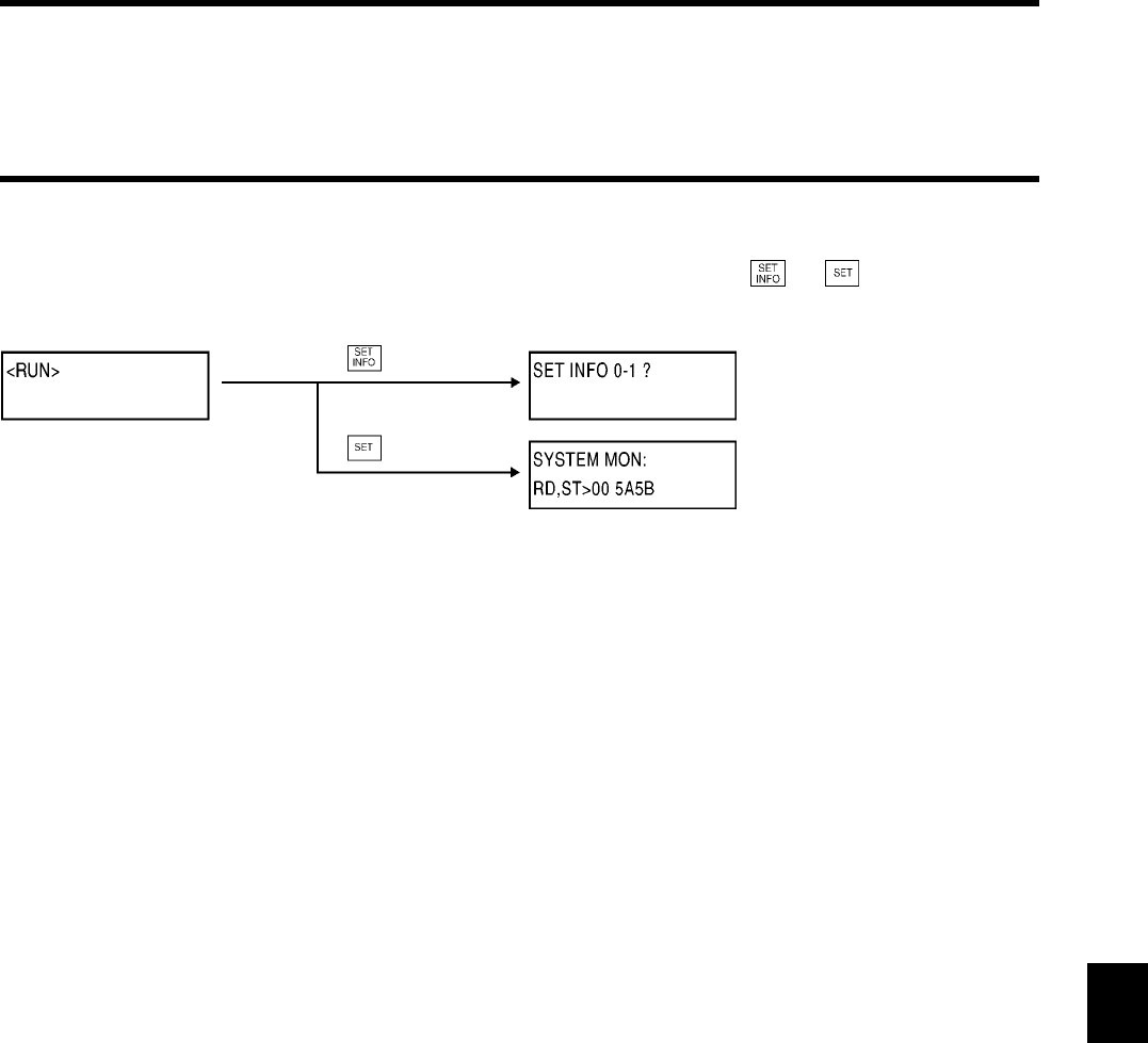
7-5 Functions
7-9
7-5-2-4 Accepting Key in Initial Screen of Run Mode
When the key switch is set to RUN, an initial screen of RUN mode is appears. In this screen, the and keys only can be
accepted.
Shows the display information selec-
tion screen.
Shows the controller execution status
screen.
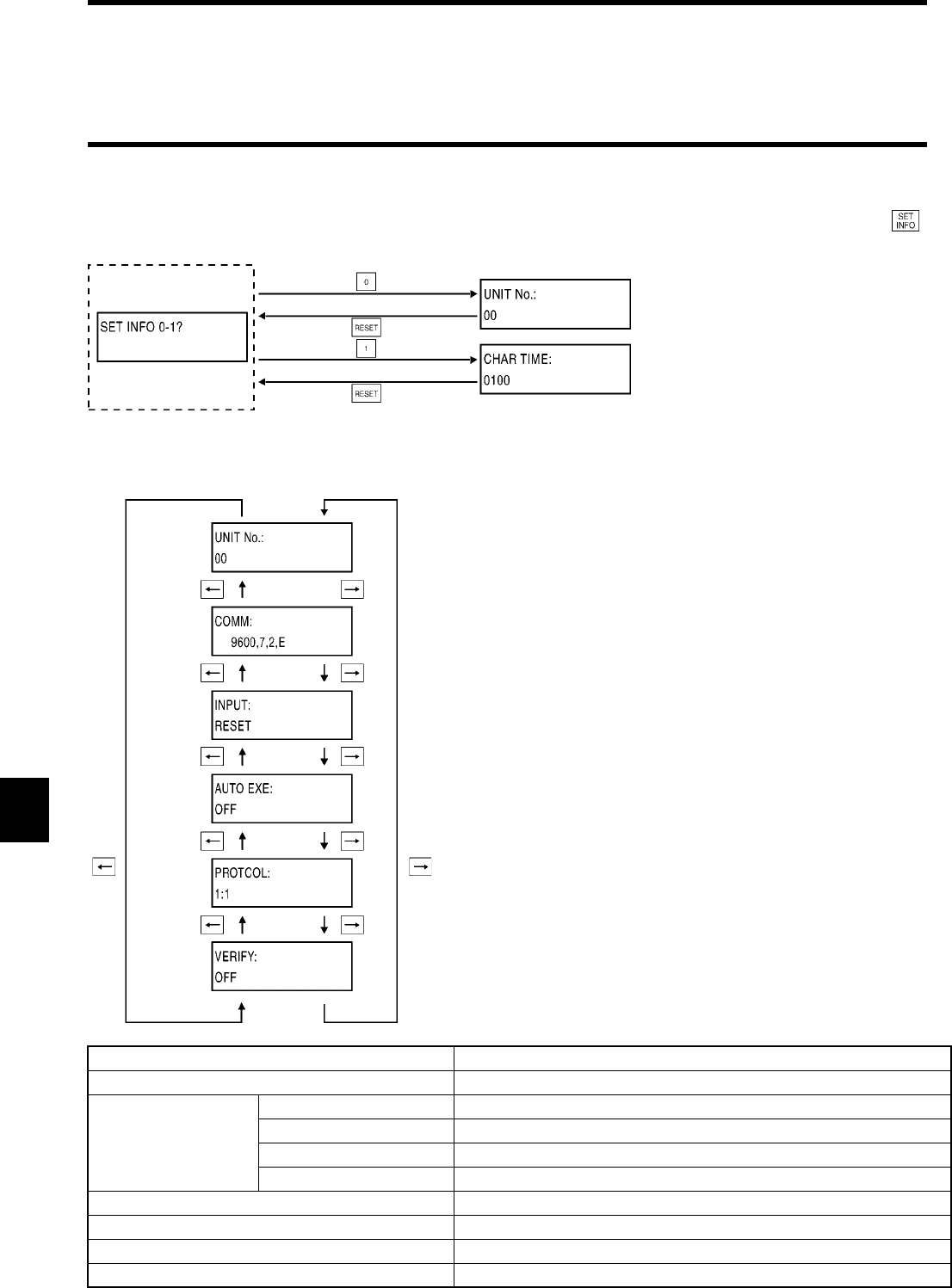
7-5 Functions
7-10
7-5-3 Displaying Details of Setting
This function of displaying details of setting of the programming console displays every item of controller setting. By pressing the
and then 0 or 1 key, an item to be displayed can be selected.
♦Dip switch setting information [0]
The dip switch setting information shows every item of controller setting specified by the dip switch.
The items are shown as follows:
Item Display
Node No. 00 to 31
RS-232C communi-
cation setting
Communication speed 9600, 19200, 38400, 115200
Data length 7, 8
Stop bit 1, 2
Parity E, O, N
Input function changeover RESET, TRIGGER
Operation mode at startup OFF, ON
Protocol designation 1:N, 1:1
Verification at writing OFF, ON
Shows the dip switch setting information
display screen.
Shows the parameter information display
screen.
Shows a node number.
Shows the RS-232C setting.
Shows the input function setting.
Shows the execution mode.
Shows a host device.
Shows whether Write verification
is enabled or disabled.
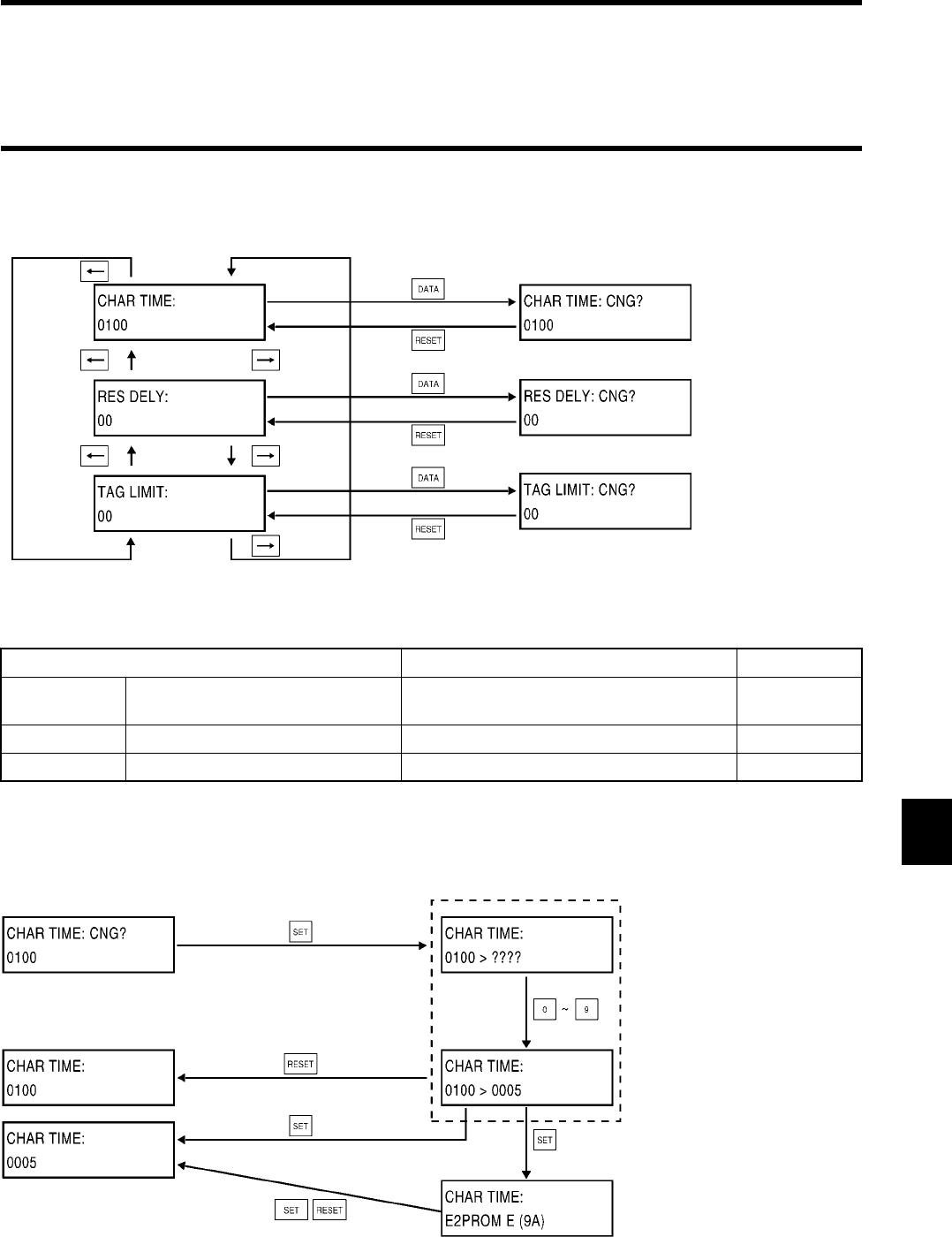
7-5 Functions
7-11
♦Parameter information [1]
The parameter information shows every item of controller setting stored in internal nonvolatile memory.
The items are shown as follows:
♦Parameter setting change
In the parameter setting change, you can change the controller setting stored in internal nonvolatile memory. The figure below shows
the character interval monitoring time as an example. When you change any other parameter, the sequence is the same.
Item Display Value
CHAR TIME Character interval monitoring time Other than 9600 bps: 0001 to 9999
9600 bps : 0002 to 9999
x 1 m-second
RES DELY Response Ready time 00 to 99 x 1 m-second
TAG LIMIT Communication restriction time 00 to 99 x 10 m-second
Parameter information display Parameter information display
* The MONITOR mode only.
EEPROM error
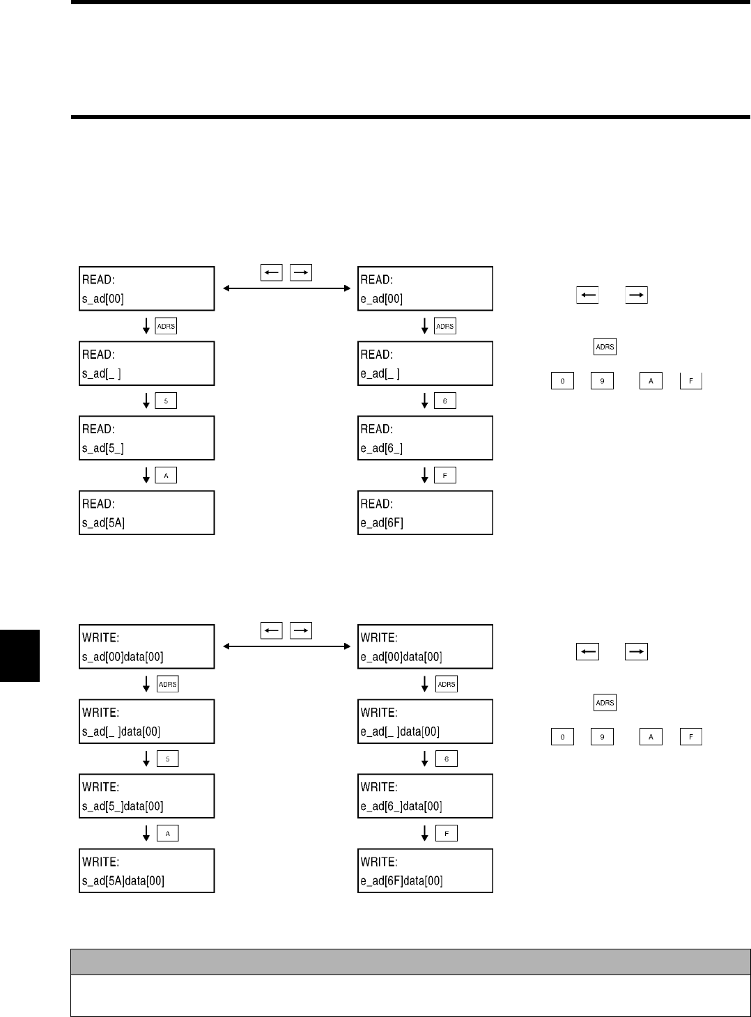
7-5 Functions
7-12
7-5-4 Address Setting
In this screen, you can specify the first address and end address, from which a data is read, to which a data is written and to be tested.
7-5-4-1 For Reading
An example to set the start address to 5Ah and the end address to 6Fh is shown below.
7-5-4-2 For Writing
An example to set the start address to 5Ah and the end address to 6Fh is shown below.
Correct Usage
• The start address value must be equal to the end address value or less.
• When you use the available designation range, check the tag memory capacity.
You can select the start address and end
address with and .
When you press , the screen is ready to
accept the address input. The available charac-
ters are to and to .
The start address value must be equal to the
end address value or less. If the start address
value is more than the end address value, an
address error occurs during the communication.
Also, if the address value more than 7Fh is
specified, an address error occurs.
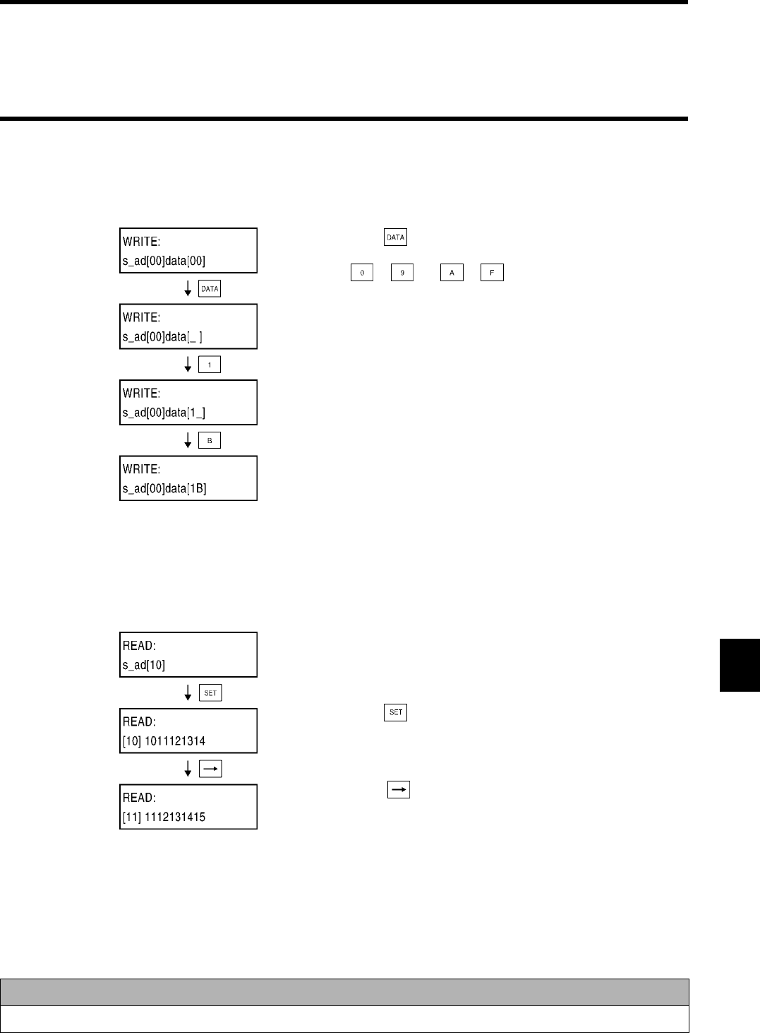
7-5 Functions
7-13
7-5-5 Data Setting
In this screen, you can specify a written data in two hexadecimal digits within 00 and FF.
Setting a data in 1B:
7-5-6 Reading/Writing Data
7-5-6-1 Reading
In this screen, you can read a data from any address of the tag and display it.
Correct Data
When you use the available designation range, check the tag memory capacity.
When you press the key, the screen is
ready to accept the address entry. The avail-
able keys are to and to .
Set the start address to 10h and the end
address to 1Fh.
When you press the key, a data is read out of
the tag and a maximum of 4 bytes of data beginning
with the specified start address is displayed.
When you press the key, the start address
value increases one. Then, the first address of the
displayed 4 bytes of data is changed.
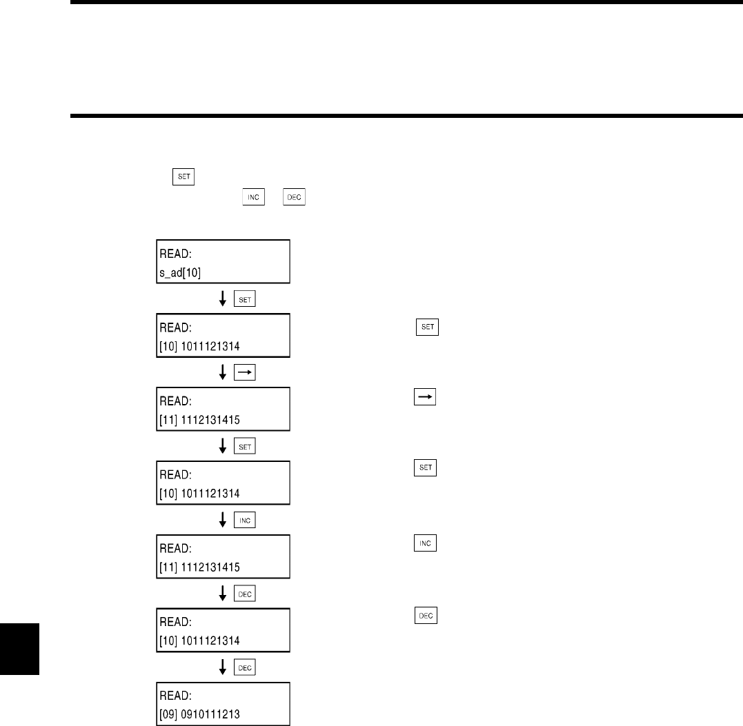
7-5 Functions
7-14
7-5-6-2 Reading Again
When you press the key again after reading the content of tag, you can read the data again according to the specified start address
and end address. When you press or , the start address value and end address value increase or decrease one. Then, the data
is read again.
Set the start address to 10h and the end
address to 1Fh.
When you press the key, a data is read out of
the tag and a maximum of 4 bytes of data beginning
with the specified start address is displayed.
When you press the key, the start address
value increases one. Then, 4 bytes of data from the
start address is shown.
When you press the key, a data is read out of
the tag again.
When you press the key, the start address
value and end address value increase one and the
data is read out of the tag again.
When you press the key, the start address
value and end address value decrease one and the
data is read out of the tag again.
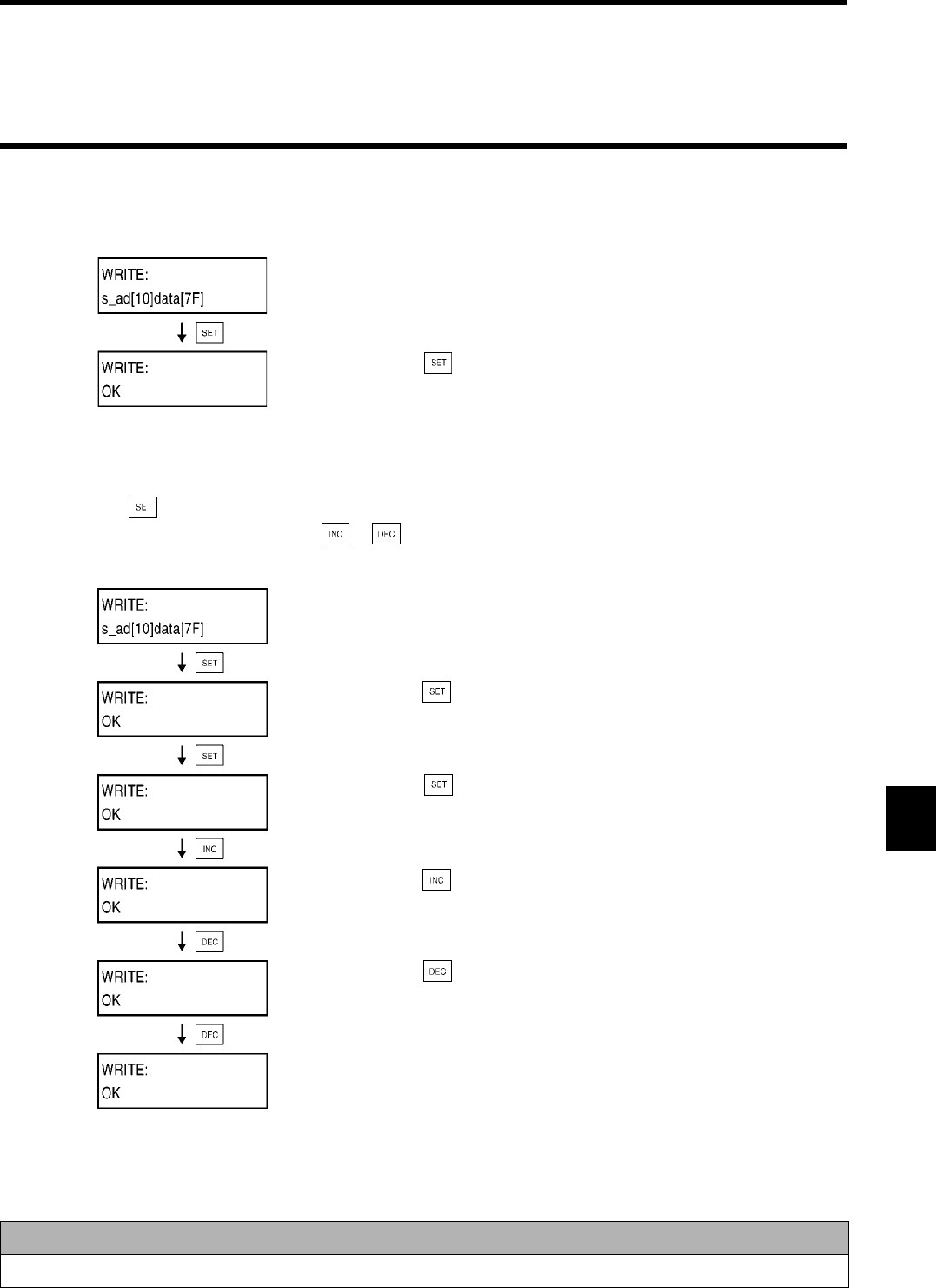
7-5 Functions
7-15
7-5-6-3 Writing
In this screen, you can write any data into any address of the tag. The same data is written into all the specified areas.
7-5-6-4 Writing Again
When you press the key again after writing a data into the tag, you can write the data into the tag again according to the specified
start address and end address. When you press the or key, the start address value and end address value increase or decrease
one. Then, the data is written into the tag again.
Correct Data
When you use the available designation range, check the tag memory capacity.
Set the start address to 10h, the end address to
1Fh and a data to 7F.
When you press the key, the data is writ-
ten into the tag. When the data has been writ-
ten correctly, "OK" is shown.
Set the start address to 10h, the end address to
1Fh and a data to 7F.
When you press the key, the data is writ-
ten into the tag. When the data has been writ-
ten correctly, "OK" is shown.
When you press the key, the data is writ-
ten into the tag again.
When you press the key, the start address
value and end address value increase one and
the data is written into the tag again.
When you press the key, the start address
value and end address value decrease one and
the data is written into the tag again.
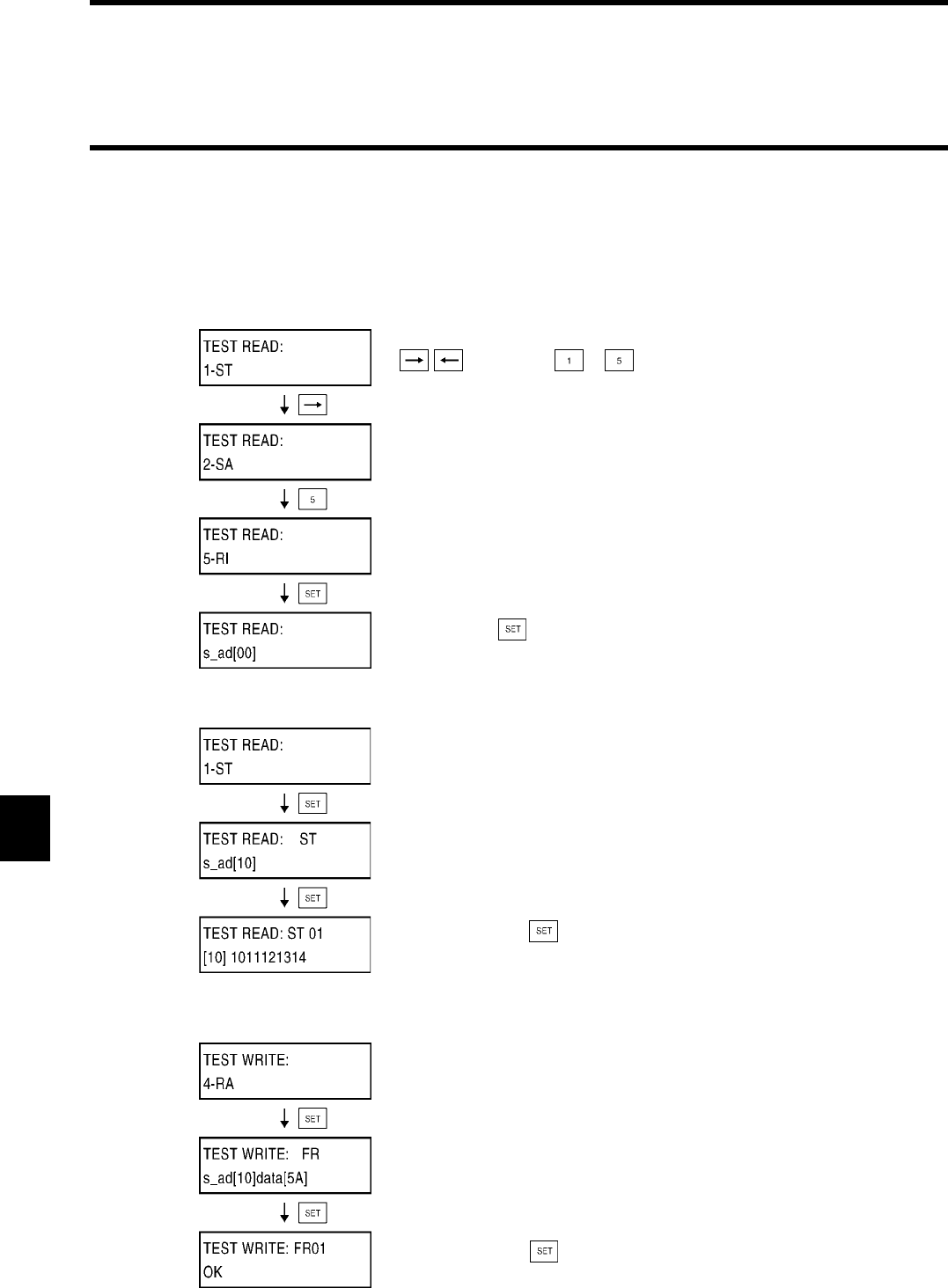
7-5 Functions
7-16
7-5-7 Test
When you check the position of antenna and tag in an applicable communication mode, you can execute the communication in a test
operation to judge whether the location and relative speed are suitable or not.
7-5-7-1 Setting Communication Mode
When you execute the Test Reading and Test Writing, you need to specify a communication mode first.
7-5-7-2 Test Reading
7-5-7-3 Test Writing
Specify a communication mode. Using the
/ key(s) or the to keys,
change a communication mode to be displayed.
Decide with the keys.
Specify the Single Trigger mode as a communi-
cation mode.
Specify the start address and end address.
When you press the keys, the number of
repeats and a data of tag are displayed.
Specify Repeat Auto as a communication
mode.
Specify the start address, end address and data
to be written.
When you press the key, the number of
repeats and the result are displayed.
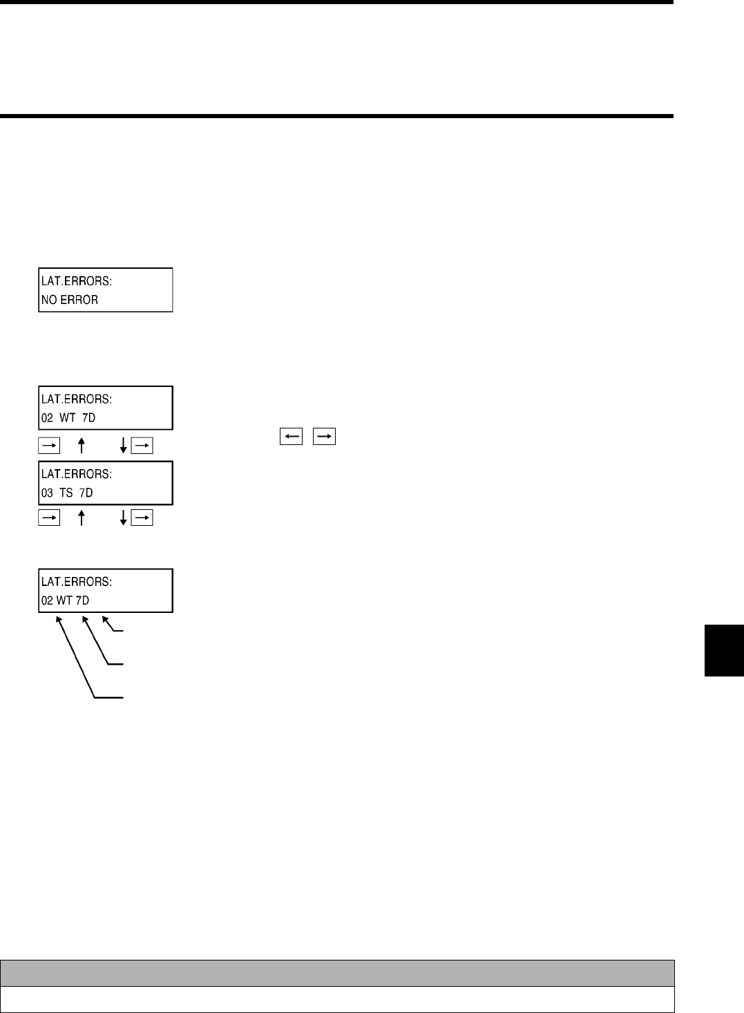
7-5 Functions
7-17
7-5-8 Reading Latest Error Information
The controller can store a maximum of 30 errors occurred in the RUN mode after the power supply turns on. When the controller stores
30 errors, if an error occurs, the oldest error is deleted from the controller memory and the new one is stored. When the power supply
turns off or the system is reset, all the stored errors are erased.
•No error occurs
•An errors occur
Correct Usage
If you want to keep the details of errors, neither turn off the power supply nor reset the system.
If any error does not occur, "NO ERROR" is dis-
played.
If any errors occur, the stored errors are read
out in reverse order of occurrence. The error
information is displayed in order of occurrence
with the / key(s).
As shown in this screen, the details of the latest
error information are the error occurrence num-
ber, command code and error code. For the error
code, refer to "5-10 Termination Code List".
Error Code
Command Code
Error Occurrence Number
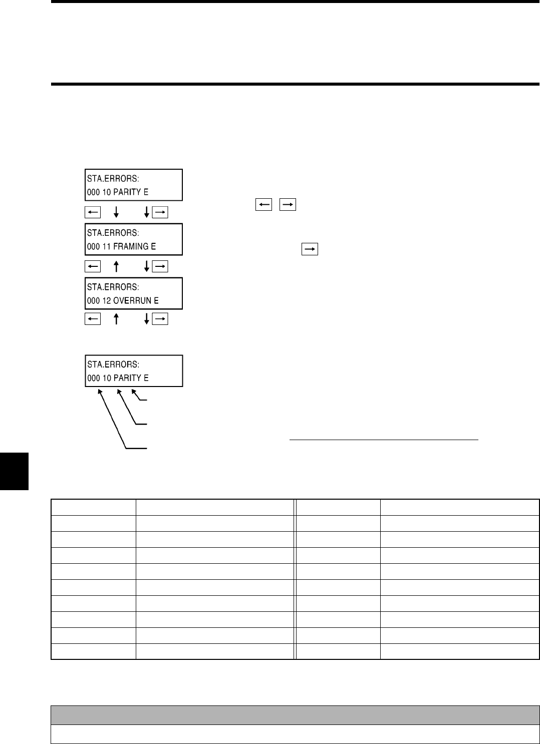
7-5 Functions
7-18
7-5-9 Statistic Error Information
The controller adds the number of error occurrences per error at every error occurrence. At the same time, the controller calculates
MCBF. Those data are all stored in memory. However, when the power supply turns off or the system is reset, all the stored data are
erased.
♦Error Indication List
Error Code Error Name Error Code Error Name
10 PARITY E 70 COM.DC E
11 FRAMING E 71 VERIFY E
12 OVERRUN E 72 NO DC E
13 FCS_E 7A ADRS E
14 FORMAT E 7B WT AREA E
15 RUN E 7C ANT E
18 FRAME E 7D PROTECT E
7E ID SYS1 E
9A E2PROM_E 7F ID SYS2 E
Correct Usage
If you want to keep the statistic error information, neither turn off the power supply nor reset the system.
Those are read out per error code in ascending
numeric order of error code number. The error
information is changed and displayed with the
/ key(s).
MCBF = Total number of host commands / num-
ber of total error occurrences
When the details of all the error occurrences
have been displayed, MCBF is displayed by
pressing the key.
As shown in this screen, the details of the statis-
tic error information are the number of error
occurrences, error code and error name. A
maximum number of error occurrences is 999.
No error is added any more.
Error Name
Error Code
Number of Error
Occurrences
Total number of commands
Communication error/ Number of total system error occurrences
MCBF =

7-5 Functions
7-19
7-5-10 Execution Monitor
In this screen, you can monitor a command, which the controller received, and the execution result in the RUN mode.
Termination code
Received command
This screen shows the received command and
termination code. If there are any received
command, communication designation, termi-
nation code and response data in the tag com-
munication, the first 4 characters of the
response data are displayed.

7-20
8-1
♦Items to be checked
Before performing a trial operation, check the following items:
♦Trial operation procedure
♦Off-line test with a programming console.
By using the programming console, you can test the communication between an antenna and tag without connection to a host device.
Use this off-line test to check the installation position and movement speed before the trial operation. For how to operate, refer to
"Chapter 7 How to Use Programming Console".
♦Communication test to a host device
You can test the communication between the controller and host device with a test command. Before performing a trial operation of the
entire system, you can check the cable connection and communication process.
• Create a simple communication program and let the host device send a test command.
• If the communication system is correct, the controller returns received data.
No. Items to be checked Checking Page
1 Connection of power supply and I/O
cable
• Whether wiring is correct.
• Whether terminal screws are tightened completely.
3-10
2 Setting of dip switch • Whether the node number is set properly.
• Whether the communication is set properly.
• Whether the operation mode is set properly.
• Whether the protocol is set properly.
3-3
3-4
3 Connection of antenna Whether the antenna is connected properly. 3-8
4 Connection to a host device Whether the RS-232C connector is connected properly. 3-12
5 Location of antenna and tag Whether the antenna and tag are located properly. Chapter 9
Turns on the power supply.
Off-line test
with a programming console.
On-line test
with a host device.
Trial operation of system.
End.
• Check the power supply voltage and power supply terminal connection.
• Check whether the RUN LED of ID controller turns on.
Check the communication between an antenna and tag without connection to a host
device (or with connection to the host device).
Check the communication between a host device and ID controller with a test command.
Check a total system operation with an actual command.
Chapter 8 From Startup to Run
8-1 Trial Operation
8-2
The controller diagnoses many items to shorten the system down time preparing for error. When an error occurs, depending on a type of
error, you may read out the details of error through the programming console.
♦Details of error
Errors detected by the controller are classified into the two types of errors. One terminates an operation and the other does not terminate
any operation.
•Error which terminates an operation
When a hardware error has occurred in the controller, the CPU operation is terminated and NORM/ERR (red) turns on.
•Error which does not terminate an operation
When an error in the communication between the controller and host device (host communication error) or between the antenna and tag
(communication error), the ERR LED turns on. A maximum of 30 errors are stored in memory. When 30 errors are stored in memory,
if an error occurs, the oldest error is deleted from memory and the new one is stored. By using the programming console, you can read
out the details of those errors and, moreover, the total number of occurrences per error.
: Turns on
: Turns off
* Turns on once when an error occurs.
Items LED Display
RUN COMM NORM ERR
Normal operation Waiting for a command
Communicating with a tag
Communication with a tag completed correctly
Error which terminates
an operation
CPU error
Error which does not ter-
minate an operation
Communication error *
Host communication error *
8-2 Diagnosis Function

8-3
Main six causes of troubles in V670 Series are as follows:
• External device failure
• Controller failure
• Antenna failure
• Cable failure
• Tag failure
• Others
♦Host communication error
♦Communication error
♦System error
Error Code Name Description
"10" Parity error A parity error has occurred in any character of command.
"11" Framing error A framing error has occurred in any character of command.
"12" Overrun error An overrun error has occurred in any character of command.
"13" FCS error FCS of received command is invalid.
"14" Format error
A command format is incorrect. Character interval has exceeded a preset time.
"15" Execution status error Communication designation is Input Trigger (SI/RI/PI) when input setting
is RESET. The "MO" command was executed when no operating condi-
tion is registered.
"18" Frame length error A command string more than 300 characters was received.
Error Code Name Description
"70" Communication error An error has occurred during the communication with a tag and the com-
munication cannot be completed correctly.
"71" Verification error
Correct data cannot be written into a tag (only when verification is enabled).
"72" No-tag error
There is no tag in a communication area of antenna when a trigger system
command is executed. In a command which performed communication des-
ignation of "st", there is no tag, which communicated immediately before, in a
communication area of antenna. The antenna is not connected.
"74" Outstanding tag error In polling query, a communication process has not yet been completed.
"7A"
Address designation error Designation of process address is unsuitable and the execution is impossible.
"7D" Write Protect error Something was written into a write-protected page.
"7E" Lock error Writing into a locked area has been specified.
"7F" Tag error Communication has been made to unavailable tag (password is not spec-
ified, etc.).
Error Code Name Description
"7C" Antenna section error No communication can be executed due to antenna trouble.
"9A" EEPROM error An error in writing into/reading from nonvolatile memory in the controller
(the SP/SE command). The "MO" command was executed under invalid
operating condition.
Correct Usage
The details of those error are all stored in the controller and you can read out an error code or error message through the
programming console.
8-3 Errors and Countermeasures
Must be repaired.

8-4
To maintain V670 Series in the best condition, you need to inspect it daily or periodically. V670 Series mainly consists of semiconduc-
tor components which have a long life. However, the following malfunctions are expected depending on the service environment or
operating condition.
(1) Deterioration of element due to over-voltage or over-current.
(2) Deterioration of element due to long-term stress arisen from use in a high-temperature site.
(3) Deterioration of insulation or imperfect contact of connector due to unsuitable humidity or dust.
(4) Imperfect contact of connector or corrosion of element due to corrosive gas.
♦Inspection item
No. Inspection Item Inspection Criterion Remarks
1 Fluctuation of power sup-
ply voltage
(1) Check at a terminal block of
power supply whether the
criterion is satisfied.
Within the specifications
for power supply voltage.
Tester.
(2) Check whether instanta-
neous power failure occurs
frequently and whether volt-
age fluctuates considerably.
Within a allowable voltage
fluctuation range.
Power supply
analyzer.
2 Ambient environment
(a) Temperature
(b) Humidity
(c) Vibration or impact
(d) Dust
(e) Corrosive gas
(a) Within the specifications.
(b) Within the specifications.
(c) Influence of vibration or
impact of machines.
(d) Adherence or sedimenta-
tion of dust or foreign mat-
ter.
(e) Discoloration or corrosion in
a metal part.
(a)
Within the specifications.
(b)
Within the specifications.
(c)
Within the specifications.
(d)
Neither dust nor foreign
material is acceptable.
(e)
Neither discoloration nor
corrosion is acceptable.
Lowest tempera-
ture thermometer.
Hygrometer.
3 Panel conditions
(a) Whether the panel is
ventilated.
(b) Whether packing mate-
rial of sealed structure
is deteriorated.
(a) Check whether natural ven-
tilation, forced ventilation
and cooling are performed.
(b) Check whether packing
material in the panel is
removed or damaged.
(a) Ventilation must be
made properly.
Temperature must be
within -10 to +55°C.
(b) Any damage is unac-
ceptable.
—
4 Power supply for I/O
(a) Voltage fluctuation
(b) Ripple
Check at a terminal block of
every I/O section whether crite-
rion is satisfied.
Within the specifications. Tester.
Oscilloscope.
5 Mounting state (1) Whether every device is
fixed tightly.
Every device must be fixed
tightly.
—
(2) Whether every connector is
inserted completely.
Every connector must be locked
properly and fixed by screws.
—
(3)
Whether terminal block screws
are tightened completely.
The terminal block screws
must be tightened completely.
—
(4) Whether wire is not dam-
aged.
The wire must not be dam-
aged.
—
(5) Whether condition between
a tag and antenna is within
the specifications.
The condition must be
within the specifications.
—
(6) Whether grounding com-
plies with the Class D (con-
ventional Class III).
—
6 Error logging Check the details of error. —
8-4 Maintenance and Inspection
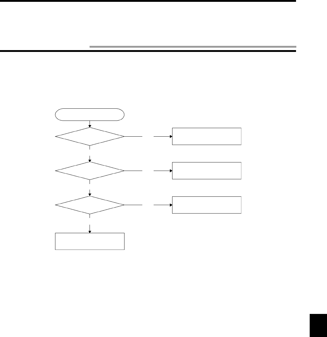
8-5
When an error has occurred, grasp the situation fully, check whether the error occurs repeatedly or not, judge the relation to any other
devices properly and check according to the flow below.
♦Main check flow
Judge this main check flow according to the details of error.
Main check flow
Check
whether the system connection is
correct.
Check
whether the host communication is
correct.
Correct
Wrong
To the system connection
check flow. Page 8-6.
To the host device check flow.
Page 8-7.
Correct
Wrong
Check
whether the communication to a tag
is correct.
Correct
Wrong
To the communication check
flow. Page 8-8.
Replace the controller with
another one.
8-5 Troubleshooting
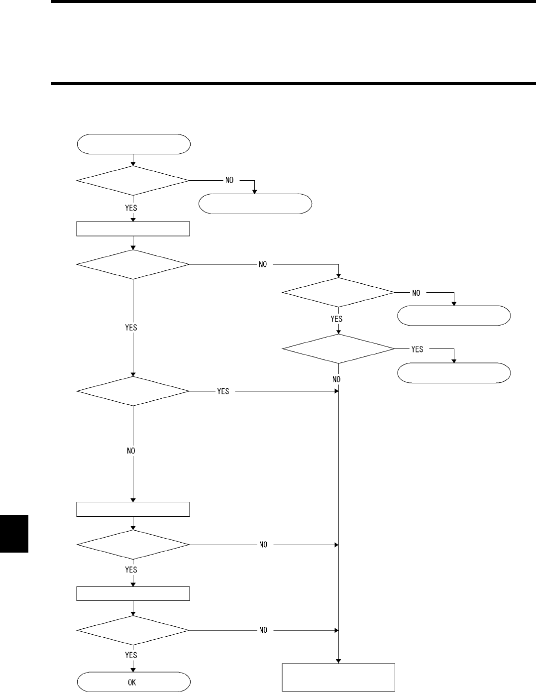
8-5 Troubleshooting
8-6
♦System connection check flow
Start
Check
whether the connectors and cables are con-
nected correctly.
Connect them correctly.
Turn on the power supply.
Does RUN LED turn ON?
Check
whether the specified volt-
age is supplied.
Supply the specified voltage.
Does reset input turn ON?
Turn OFF reset input.
Does NORM/ERR (red) turn
ON?
Connect the programming console.
Does the display work?
Input the password.
Do the key switch and display
match?
Replace the controller with
another one.
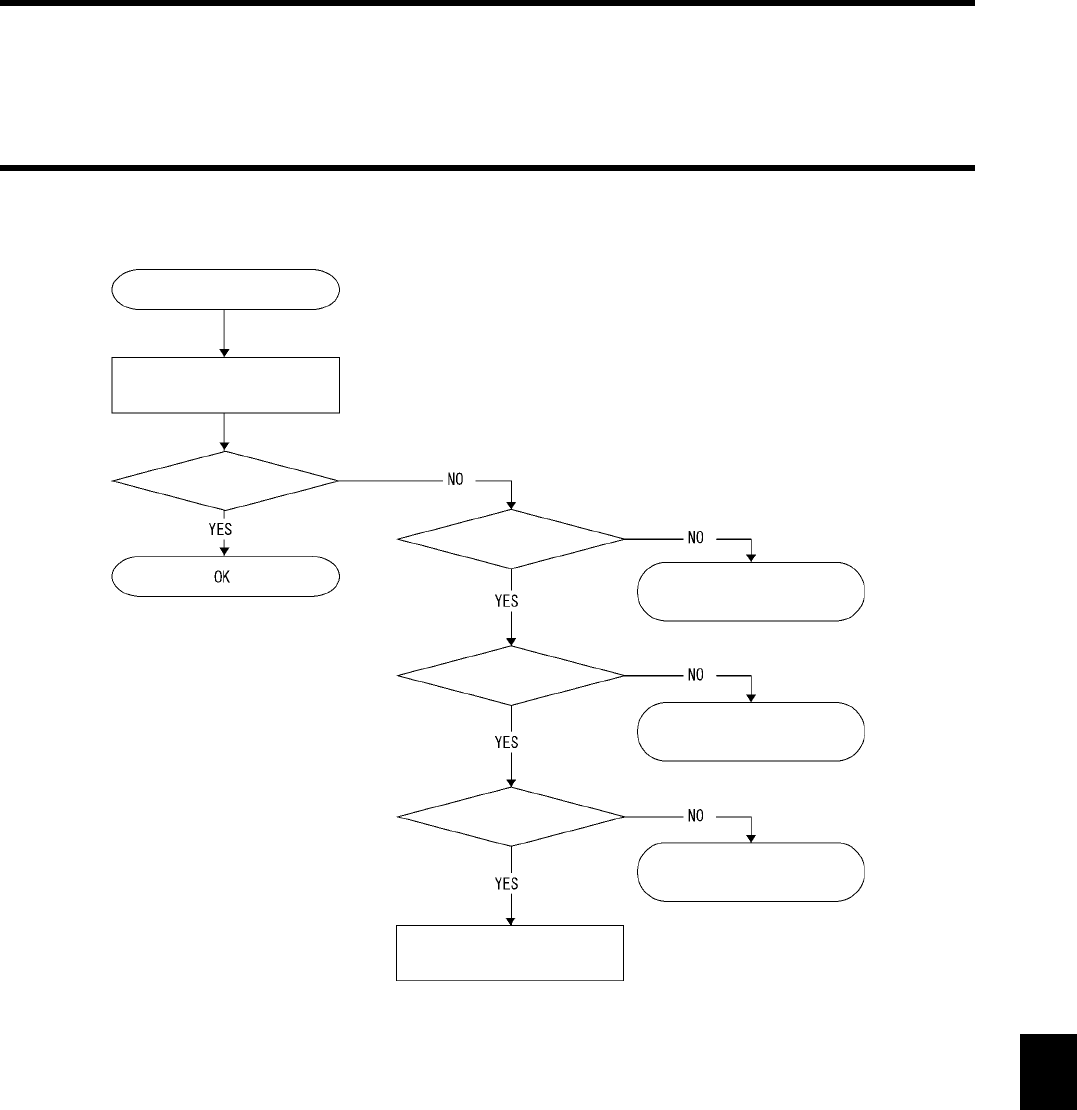
8-5 Troubleshooting
8-7
♦Host communication check flow
Start
Send the TS command from a
host device.
Is the response correct
Is the communication for-
mat correct?
Is
the communication cable \
connector wired correctly?
Correct the communication
format.
Modify the connector wiring.
Does the host device work
correctly?
Modify the host program or
replace the host device with
another one.
Replace the controller with
another one.
8-5 Troubleshooting
8-8
♦Communication check flow
Start
Can
the programming console be
used?
Connect the programming console and
turn ON the power supply in the MONI-
TOR mode.
Execute Test Writing in
the Single Auto mode
Turn ON the power supply without con-
necting the programming console and
connect the host device.
Send the Write com-
mand in the Single Auto
mode.
The COMM
LED turns on and then
turns off.
Is the movement speed correct?
Decrease the move-
ment speed.
Is the tag
correct?
Replace the tag with
another one.
Is the opposed condition
correct?
Adjust the distance and
restrain flutter.
Is
the tag correct?
Replace the tag with
another one.
Are
the tag memory capacity and set
address correct?
Specify the address
again.
Is
the antenna cor-
rect?
Replace the antenna
with another one.
Is
the Write Protect setting cor-
rect?
Disable Write Protect.
Is the tag correct?
Replace the tag with
another one.
Is the tag correct?
Replace the tag with
another one.
Is
the distance between the antenna
and tag correct?
Adjust the distance.
Is the tag correct?
Replace the tag with
another one.
Is
the communication with a tag exe-
cuted correctly?
Is the communication ended cor-
rectly?
Replace the ID control-
ler with another one.
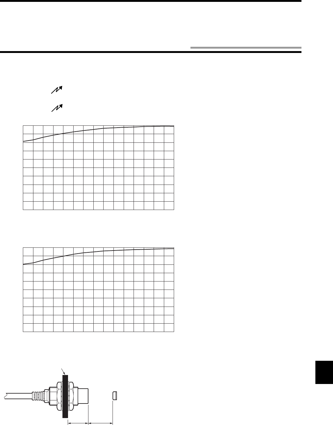
9-1
Even if the antenna is mounted on any metallic material, the antenna is not affected. However, be sure to check the antenna when you
install it.
•Model V670-H11 Model V670-D13F03
The metal has hardly any influence on the performance of Model V670-H11. However, be sure to check the performance after installation.
•Model V670-H51 Model V670-D13F01 (H)
Metal: Iron
Metal: Aluminum
0123456789101112131415
Distance between the sensing head of antenna and metal (mm)
100
80
90
70
60
50
40
30
20
10
0
Communication range ratio (%)
* Assume that the communication distance
without metal is 100%.
0123456789101112131415
Distance between the sensing head of antenna and metal (mm)
100
80
90
70
60
50
40
30
20
10
0
Communication range ratio (%)
* Assume that the communication distance
without metal is 100%.
Antenna
Tag
Metal
Distance between
metal and sensing
head of antenna
Communication
range
Chapter 9 Characteristic Data Depending on Operating Condition (Reference)
9-1 Influence of Metal of Antenna (Reference)
9-1 Influence of Metal of Antenna (Reference)
9-2
•Model V670-H51Q Model V670-D13F01 (H)
Metal: Iron
Metal: Alminum
0123456789101112131415
Distance between the sensing head of antenna and metal (mm)
100
80
90
70
60
50
40
30
20
10
0
Communication range ratio (%)
* Assume that the communication distance
without metal is 100%.
0123456789101112131415
Distance between the sensing head of antenna and metal (mm)
100
80
90
70
60
50
40
30
20
10
0
Communication range ratio (%)
* Assume that the communication distance
without metal is 100%.
Antenna
Tag
Metal
Distance between
metal and sensing
head of antenna
Communication
range
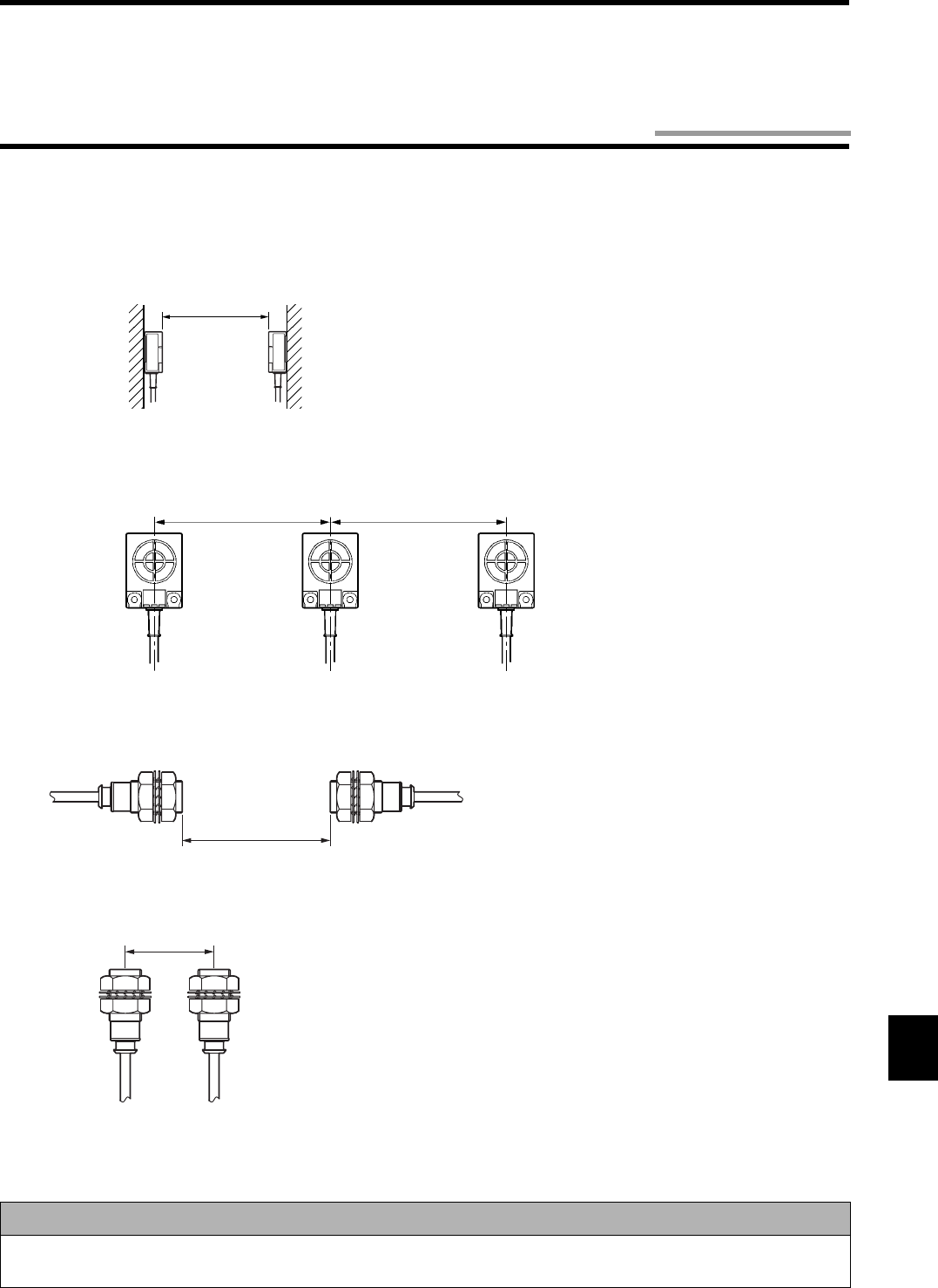
9-3
When you use several antennas, to prevent the mutual interference between them, keep the specified distance between those antennas as
shown below.
•Model V670-H11
• Installing the antennas facing each other
• Installing the antennas in parallel
•Model V670-H51 (Q)
• Installing the antennas facing each other
• Installing the antennas in parallel
Precaution for Correct use
With the above description as reference, carry out a preliminary test or take other appropriate measures to ensure successful installa-
tion of the product.
100 mm or more
100 mm or more 100 mm or more
70 mm or more
30 mm or more
9-2 Mutual Interference between Antennas (Reference)
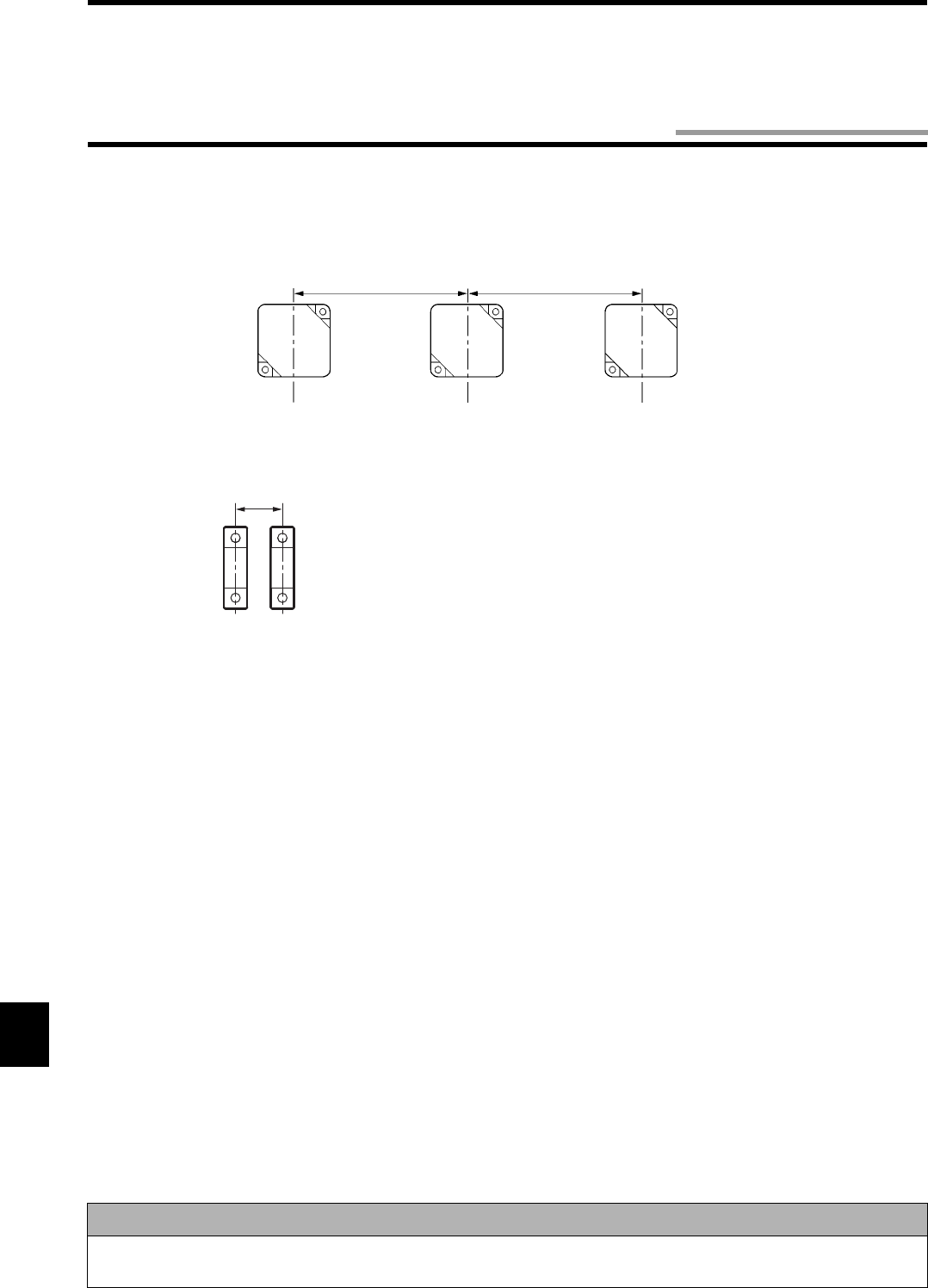
9-4
When you use several tags, to prevent the mutual interference between them, keep the specified distance between those tags as shown
below.
•Model V670-D13F03
•Model V670-D13F01 (H)
Precaution for Correct use
With the above description as reference, carry out a preliminary test or take other appropriate measures to ensure successful installa-
tion of the product.
70 mm or more 70 mm or more
16 mm or more
9-3 Mutual Interference between Tags (Reference)
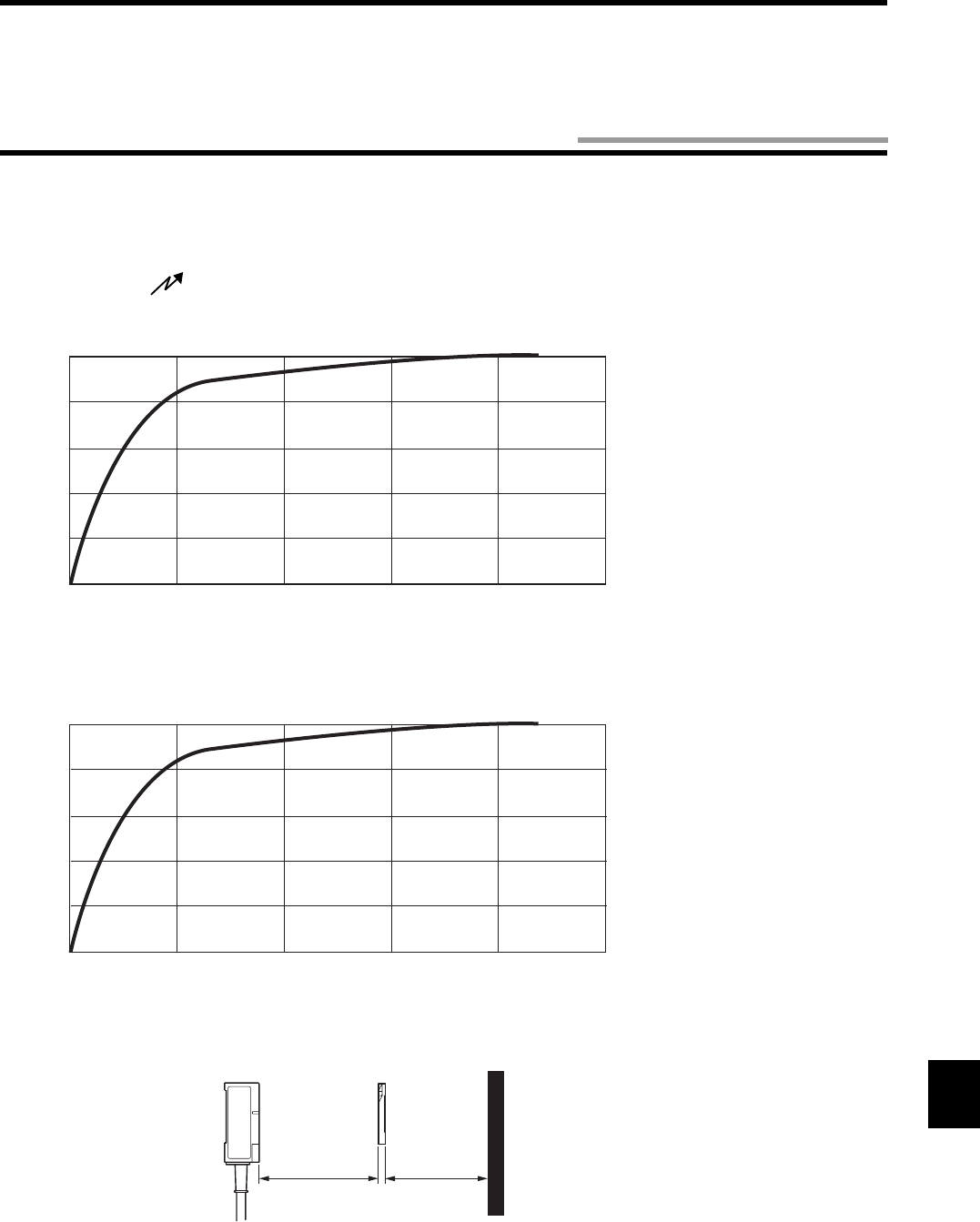
9-5
When you install the tag, take into consideration the influence of back metal.
If there is any metallic material behind the tag, the communication range deteriorates. The characteristic of communication range dete-
rioration depending on the distance between the tag and back metal of tag (the same size as antenna) is shown below.
•Model V670-H11 Model V670-D13F03
0
0
100
80
60
40
20
20 40 60 80 100
Distance between metal and tag (mm)
Communication range ratio (%)
0 20406080100
Distance between metal and tag (mm)
Communication range ratio (%)
0
100
80
60
40
20
Antenna Metal
Tag
Distance
between back
metal and tag
Communication
range
* Assume that the communication
distance without metal is 100%.
* Assume that the communication
distance without metal is 100%.
Metal: Aluminum
Metal: Iron
9-4 Influence of Back Metal of Tag (Reference)
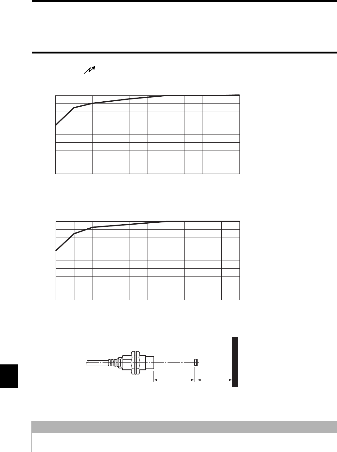
9-4 Influence of Back Metal of Tag (Reference)
9-6
•Model V670-H51 Model V670-D13F01 (H)
Precaution for Correct use
With the above description as reference, carry out a preliminary test or take other appropriate measures to ensure successful installa-
tion of the product.
0246891357 10
Distance between metal and tag (mm)
Communication range ratio (%)
0
100
80
60
40
20
10
90
70
50
30
0246891357 10
Distance between metal and tag (mm)
Communication range ratio (%)
0
100
80
60
40
20
10
90
70
50
30
Antenna
Metal
Tag
Distance
between back
metal and tag
Communication
range
* Assume that the communication
distance without metal is 100%.
* Assume that the communication
distance without metal is 100%.
Metal: Aluminum
Metal: Iron
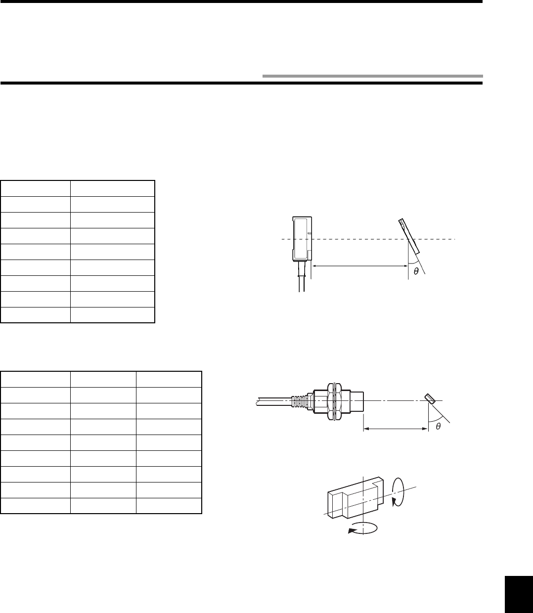
9-7
A maximum communication range can be obtained by installing a tag so that the antenna surface and tag surface can be parallel to each
other. When you install the tag, take into consideration the influence of tag angle.
If the tag surface is not parallel to the antenna surface, the communication range deteriorates. The characteristic of communication
range deterioration depending on the tag angle is shown below.
•Model V670-D13F03
Communication range deterioration
•Model V670-D13F01 (H)
Communication range deterioration
The tag makes contact with the sensing head of
antenna when it is tilted to 60 degrees or more in
the longitudinal direction (*1) in the above mea-
surement.
θ° Deterioration ratio
00%
10 0%
20 1%
30 2%
40 3%
50 4%
60 9%
70 18%
θ° *1 *2
10 2% 2%
20 2% 3%
30 2% 6%
40 2% 10%
50 2% 14%
60 ( * ) 20%
70 ( * ) 29%
80 ( * ) 41%
Model V670-H11 Model V670-D13F03
Communication range
Antenna
Tag
Communication range
*1
*2
9-5 Influence of Tag Angle (Reference)

9-8
Chemicals which affect a tag are shown below.
ABS resin and epoxy resin are used as case material and filling material, respectively. Referring to the list below, use suitable chemi-
cals. Do not use any chemicals which affect the ABS resin and epoxy resin.
Any chemicals cannot be used for explosion-proof application.
•Chemicals which cause deformation, crack, etc.
•Chemicals which may cause discoloration, swelling, etc.
•Chemicals which do not affect ABS resin nor epoxy resin.
Note: The test above is the result at a room temperature (23°C). Even if the chemicals do not affect the ABS resin or epoxy resin at the
room temperature (23°C), such chemicals may affect the resin at a high temperature or low temperature. Check the chemicals
fully in advance.
ABS Resin Epoxy Resin
Trichlene, acetone, xylene, toluene, gasoline, creosol,
methylene chloride, phenol, miclohexanone, aqua regia,
chromic acid, sulfur (90% RT), methyl ethyl ketone,
aniline, nitrobenzene, monochlorobenzene, pyridine, nitric
acid (60% RT), and formic acid (80% RT).
Aqua regia, chromic acid, sulfuric acid (90% RT), nitric
acid (60% RT), liquid ammonia, acetone, methylene chlo-
ride, phenol, and trichlene.
ABS Resin Epoxy Resin
Hydrochloric acid, alcohol, freon, sodium hydroxide,
hydrogen peroxide, benzine, sulfuric acid (10% RT), nitric
acid (10% RT), phosphoric acid (85% RT), and liquid
ammonia.
Sulfuric acid (10% RT), nitric acid (10% RT), hydrochloric
acid (30% RT), acetic acid (50% RT), nitric acid, calcium
hydroxide, benzene, creosol, alcohol, miclohexanone, tol-
uene, xylene, benzine, and grease.
ABS Resin Epoxy Resin
Ammonia, kerosene, mineral oil, developer, YUSHIRO-
KEN S50, CHEMICOOL Z, VELOCITY NO. 3, YUSHIRO-
KEN EEE-30Y, petroleum, grease, acetic acid, nitric acid,
calcium hydroxide, phosphoric acid (30% RT), hydrochlo-
ric acid (10% RT) and potassium hydroxide.
Ammonia, hydrochloric acid (10% RT), potassium hydrox-
ide, petroleum, gasoline, YUSHIROKEN S50, CHEMI-
COOL Z, VELOCITY NO. 3, YUSHIROKEN EEE-30Y.
9-6 Chemical Resistance of Tag (Reference)
Appendix-1
b8~b5 0000 1001
0010 0011 0100 0101 0110 0111 1000 1001 1010 1011 1100 1101 1110 1111
b4~b1 0 1 23456789101112131415
0000 0 NUL TC7(DLE)
(SP)
0@P p
0001 1
TC
1
(SOH)
DC
1
!1AQaq
0010 2 TC2(STX) DC22BRb r
0011 3 TC3(ETX) DC3#3CScs
0100 4 TC4(EOT) DC4$4DTd t
0101 5
TC
5
(NEQ)
TC8(NAK) % 5 E U e u
0110 6 TC6(ACK)
TC9(SYN)
&6FV f v
0111 7 BEL
TC10(ETB)
’7GWgw
1000 8 FE0(BS) CAN ( 8 H X h x
1001 9 FE1(HT) EM ) 9 I Y i y
1010 10 FE2(LF) SUB * : J Z j z
1011 11 FE3(VT) ESC + ; K [ k {
1100 12 FE4(FF) IS4(FS) , < L \l|
1101 13 FE
5
(CR) IS3(GS) - = M ] m }
1110 14 S0 IS2(RS) . > N ^ n ~
1111 15 S1 IS1(US) / ? O _ o
DEL
Undefined
Undefined
Undefined
Undefined
Undefined
High order
digit
Low order
digit
Column
Row
Undefined
Undefined
Undefined
Undefined
Appendix
Appendix 1 ASCII Code List
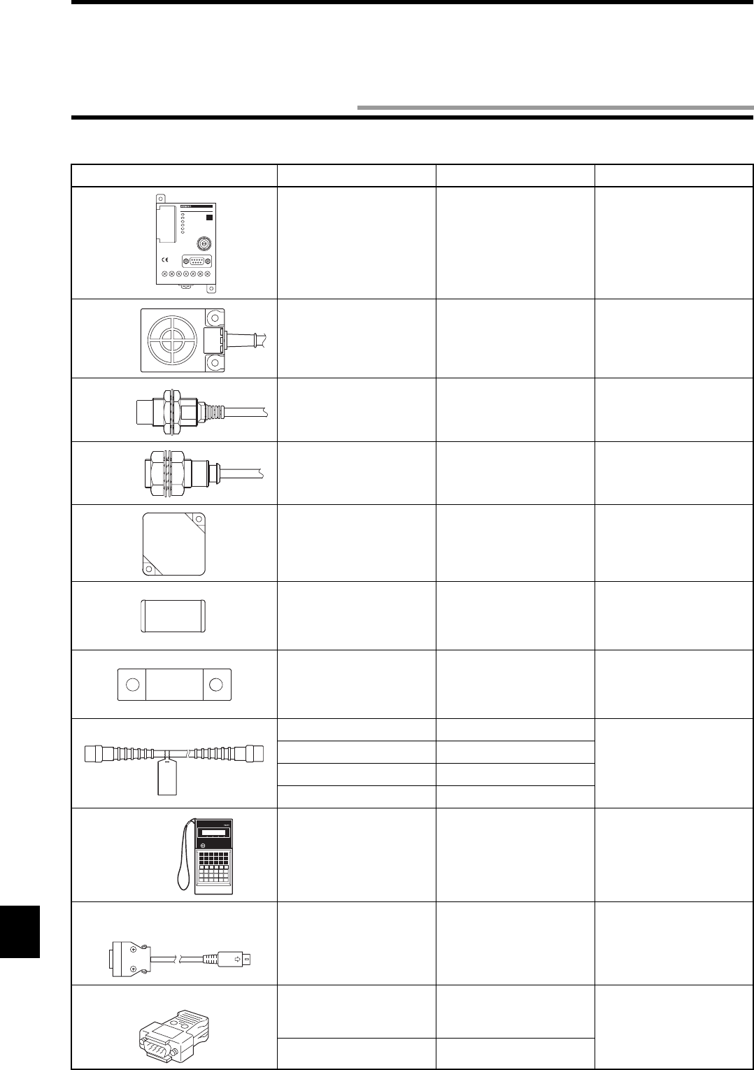
Appendix-2
♦Main unit and system components
Name/Shape Specifications Model Remarks
Controller RS-232 interface
24 VDC power supply
Outside dimension:
90 × 66 × 75 mm
Model V670-CD1D-V1 —
Antenna Outside dimension:
40 × 53 × 23 mm
Model V670-H11 —
Antenna Outside dimension:
M18 × 43 mm
Model V670-H51 —
Antenna Outside dimension:
M18 × 47 mm
Model V670-H51Q —
Tag Memory capacity:
128 bytes
Outside dimension:
40 × 40 × 4.5 mm
Model V670-D13F03 —
Tag Memory capacity:
128 bytes
Outside dimension:
8 × 16 × 3.5 mm
Model V670-D13F01 —
Tag Memory capacity:
128 bytes
Outside dimension:
8 × 28 × 3.5 mm
Model V670-D13F01H —
Junction cable 3 m Model V670-A40 For connection of
antenna and controller.
10 m Model V670-A41
18 m Model V670-A42
28 m Model V670-A43
Programming
console
— Model CR200H-PRO27 —
Programming console
connecting cable
2 m Model V700-P10 A dedicated key sheet
comes together.
Communication connector Connector plug Model XM2A-0901 One set comes with
Model V670-CD1D.
Connector hood Model XM2S-0911
V6 7 0 - CD1 D
V670-CD1D-V1
ID
PRO27
Appendix 2 Order Format List
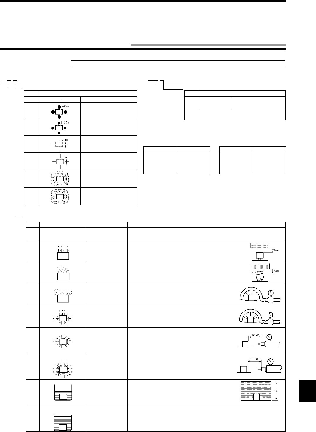
Appendix-3
•Protective Structure
Note: IP-
is classified by a test method below. Check sealing in working environment and operating conditions in advance.
♦
IEC
(International Electrotechnical Commission)
Standards
(IEC60529: 1989-11)
♦
JEM
(Japan Electrical Manufacturers’ Association)
Standards
(JEM1030: 1991)
IP- IP-
(January 1998)
Appendix 3 Protective Structure
Protective property code (International Protection)
Protective classification for "1st Symbol" solid foreign material
Class Protection Level
0 No protection.
1 Solid foreign material 50 mm or
more in diameter (hand etc.) can-
not come in.
2 Solid foreign material 12.5 mm or
more in diameter (finger etc.) can-
not come in.
3 Solid foreign material 2.5 mm or
more in diameter (wire etc.) can-
not come in.
4 Solid foreign material 1 mm or
more in diameter (wire etc.) can-
not come in.
5 Dust, which interferes a normal
operation of device or spoils the
safety, cannot come in.
6 Any dust cannot come in.
Complies with the 1st and 2nd symbols of IEC60529.
Protective classification for oil penetration.
Note) There are four other classes: “h”, “c”, “d”, and “e”.
Class Protection Level
f Oil retaining type Not affected considerably by oil
drops or oil spray in any direc-
tion.
g Oil resistance type Any oil drop or oil spray in any
direction cannot come in.
♦NEMA (National Electrical Manufacturers Association)
Table for conversion from NEMA enclosure into IEC60529. (Conversion from IEC60529 into
NEMA enclosre is unavailable.)
Note: Based on the NEMA Standards. The difference between NEMA enclosure classification and
IEC60529 is anticorrosion, rust prevention, moisture condensation on surface, etc.
NEMA250 IEC60529
1
2
3
3R
3S
IP10
IP11
IP54
IP14
IP54
NEMA250 IEC60529
4, 4X
5
6, 6P
12, 12K
13
IP56
IP52
IP67
IP52
IP54
Protective classification for "2nd Symbol" water penetration
Class Protection Level Test Method Overview (Test with fresh water)
0 No particular protection Any particular protection
is not taken to water
penetration.
No Test.
1
Protection against drop of water
Not to be affected by
water dropped vertically.
Drop water for 10 minutes using a water drop tester.
2
Protection against drop of water
Not to be affected by
water dropped deviat-
ing 15° from a vertical
line.
Drop water to an object set inclined 15° for 10 minutes (2.5 minutes per
direction) using a water drop tester.
3
Protection against water spray
Not to be affected by
water spray deviating
within 60° from a vertical
line.
Spray water in an area within 60° to the right and left from a verti-
cal line for 10 minutes using a tester shown in this figure.
4
Protection against water splash
Not to be affected by
water splash from all the
directions.
Spray water from all the directions for 10 minutes using a tester
shown in this figure.
5
Protection against water jet flow
Not to be affected by
direct water jet flow from
all the directions.
Spray water from all the directions for 1 minute per surface area
1 m2, total 3 minutes or more using a tester shown in this figure.
6 Protection against extreme
water jet flow
Not to be affected by
extreme direct water jet
flow from all the direc-
tions.
Spray water from all the directions for 1 minute per surface area
1 m2, total 3 minutes or more using a tester shown in this figure.
7
Protection against water soaking
Even if an object is
immersed in water of
specified pressure for a
specified time, any
water penetration must
not be observed.
Immerse an object at 1 m deep in water for 30 minutes (assuming
that device height is lower than 850 mm).
8 Protection against water
immersion
An object must work
always in water.
According to an agreement between a manufacturer and device user.
0.07 L/min per
spray nozzle
0.07 L/min per
spray nozzle
Water jet nozzle diameter: 6.3 mm
12.5 L/min
Water jet nozzle diameter: 12.5 mm
100 L/min

OMRON Corporation
Industrial Automation Company
Sensing Devices Division H.Q.
Industrial Sensors Division
Shiokoji Horikawa, Shimogyo-ku,
Kyoto, 600-8530 Japan
Tel: (81)75-344-7022/Fax: (81)75-344-7107
Regional Headquarters
OMRON EUROPE B.V.
Sensor Business Unit,
Carl-Benz-Str. 4, D-71154 Nufringen,
Germany
Tel: (49)7032-811-0/Fax: (49)7032-811-199
OMRON ELECTRONICS LLC
1 East Commerce Drive, Schaumburg, IL 60173
U.S.A.
Tel: (1)847-843-7900/Fax: (1)847-843-8568
OMRON ASIA PACIFIC PTE. LTD.
83 Clemenceau Avenue,
#11-01, UE Square,
239920 Singapore
Tel: (65)6835-3011/Fax: (65)6835-2711
OMRON (CHINA) CO., LTD.
Room 2211, Bank of China Tower,
200 Yin Cheng Road (M),
Shanghai, 200120 China
Tel: (86)21-5037-2222/Fax: (86)21-5037-2200

Authorized
Distributor:
Printed in Japan
0206-?C (?)
Cat. No. Z148-E1-04 Note: Specifications subject to change without notice.