Contents
- 1. User Manual
- 2. 05 User Manual_1
- 3. 05 User Manual_2
User Manual
Cat. No. NTLP
DeviceNet ID Slave
V680-HAM42-DRT
V680 Series
User’s Manual
Antennas
V680-HS51
V680-HS52
V680-HS63
V680-HS65
ID Tags
V680-D1KP52MT
V680-D1KP66T/-D1KP66MT
V680-D1KP66T-SP
V680-D2KF52M
V680-D2KF67/-D2KF67M
V680-D8KF68/-D32KF68

Introduction
Thank you for purchasing a V680-series RFID System. This manual describes the functions, performance,
and application methods needed for optimum use of the V680-series RFID System.
Please observe the following items when using the RFID System.
•Allow the RFID System to be installed and operated only by qualified specialist with a sufficient knowledge
of electrical systems.
•Read and understand this manual before attempting to use the RFID System and use the RFID System
correctly.
•Keep this manual in a safe and accessible location so that it is available for reference when required.

Introducti Section 1 Section 2 Section 3 Section 4 Section 5 Section 6
Introduction
Section 1
Section 2
Section 3
Section 4
Section 5
Section 6
READ AND UNDERSTAND THIS DOCUMENT
Product Overview
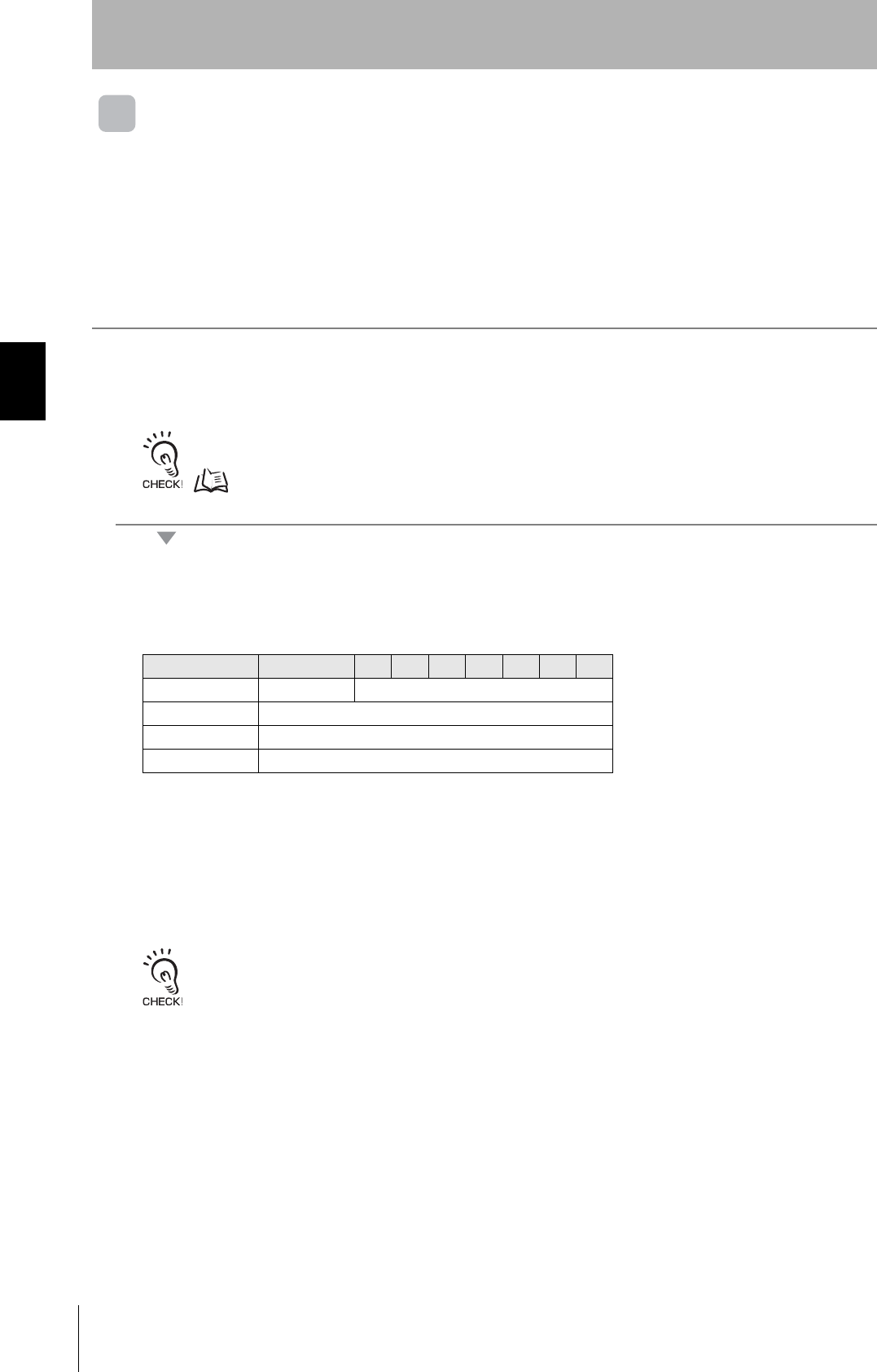
Names and Functions of Components
Functions and Operation
Installation, Connections, and Wiring
I/O Settings and Control Methods
Appendices
RFID System
V680-HAM42-DRT DeviceNet Remote ID Controller
V680-HS51 Antenna
V680-HS52 Antenna
V680-HS63 Antenna
V680-HS65 Antenna
V680-D1KP52MT ID Tag
V680-D1KP66T/-D1KP66MT ID Tag
V680-D1KP66T-SP ID Tag
V680-D2KF52M ID Tag
V680-D2KF67/-D2KF67M ID Tag
V680-D8KF68/-D32KF68 ID Tag

2
Introduction
RFID System
User's Manual
Introduction
READ AND UNDERSTAND THIS DOCUMENT
Please read and understand this document before using the products. Please consult your OMRON representative if you have any questions or comments.
WARRANTY
OMRON’s exclusive warranty is that the products are free from defects in materials and workmanship for a period of one year (or other period if specified)
from date of sale by OMRON.
OMRON MAKES NO WARRANTY OR REPRESENTATION, EXPRESS OR IMPLIED, REGARDING NON-INFRINGEMENT, MERCHANTABILITY, OR FIT-
NESS FOR PARTICULAR PURPOSE OF THE PRODUCTS. ANY BUYER OR USER ACKNOWLEDGES THAT THE BUYER OR USER ALONE HAS
DETERMINED THAT THE PRODUCTS WILL SUITABLY MEET THE REQUIREMENTS OF THEIR INTENDED USE. OMRON DISCLAIMS ALL OTHER
WARRANTIES, EXPRESS OR IMPLIED.
LIMITATIONS OF LIABILITY
OMRON SHALL NOT BE RESPONSIBLE FOR SPECIAL, INDIRECT, OR CONSEQUENTIAL DAMAGES, LOSS OF PROFITS OR COMMERCIAL LOSS IN
ANY WAY CONNECTED WITH THE PRODUCTS, WHETHER SUCH CLAIM IS BASED ON CONTRACT, WARRANTY, NEGLIGENCE, OR STRICT LIABIL-
ITY.
In no event shall responsibility of OMRON for any act exceed the individual price of the product on which liability is asserted.
IN NO EVENT SHALL OMRON BE RESPONSIBLE FOR WARRANTY, REPAIR, OR OTHER CLAIMS REGARDING THE PRODUCTS UNLESS OMRON’S
ANALYSIS CONFIRMS THAT THE PRODUCTS WERE PROPERLY HANDLED, STORED, INSTALLED, AND MAINTAINED AND NOT SUBJECT TO CON-
TAMINATION, ABUSE, MISUSE, OR INAPPROPRIATE MODIFICATION OR REPAIR.
SUITABILITY FOR USE
THE PRODUCTS CONTAINED IN THIS DOCUMENT ARE NOT SAFETY RATED. THEY ARE NOT DESIGNED OR RATED FOR ENSURING SAFETY OF
PERSONS, AND SHOULD NOT BE RELIED UPON AS A SAFETY COMPONENT OR PROTECTIVE DEVICE FOR SUCH PURPOSES. Please refer to sep-
arate catalogs for OMRON's safety rated products.
OMRON shall not be responsible for conformity with any standards, codes, or regulations that apply to the combination of products in the customer’s applica-
tion or use of the product.
At the customer’s request, OMRON will provide applicable third party certification documents identifying ratings and limitations of use that apply to the prod-
ucts. This information by itself is not sufficient for a complete determination of the suitability of the products in combination with the end product, machine,
system, or other application or use.
The following are some examples of applications for which particular attention must be given. This is not intended to be an exhaustive list of all possible uses
of the products, nor is it intended to imply that the uses listed may be suitable for the products:
• Outdoor use, uses involving potential chemical contamination or electrical interference, or conditions or uses not described in this document.
• Nuclear energy control systems, combustion systems, railroad systems, aviation systems, medical equipment, amusement machines, vehicles, safety
equipment, and installations subject to separate industry or government regulations.
• Systems, machines, and equipment that could present a risk to life or property.
Please know and observe all prohibitions of use applicable to the products.
NEVER USE THE PRODUCTS FOR AN APPLICATION INVOLVING SERIOUS RISK TO LIFE OR PROPERTY WITHOUT ENSURING THAT THE SYSTEM
AS A WHOLE HAS BEEN DESIGNED TO ADDRESS THE RISKS, AND THAT THE OMRON PRODUCT IS PROPERLY RATED AND INSTALLED FOR THE
INTENDED USE WITHIN THE OVERALL EQUIPMENT OR SYSTEM.
PERFORMANCE DATA
Performance data given in this document is provided as a guide for the user in determining suitability and does not constitute a warranty. It may represent the
result of OMRON’s test conditions, and the users must correlate it to actual application requirements. Actual performance is subject to the OMRON Warranty
and Limitations of Liability.
CHANGE IN SPECIFICATIONS
Product specifications and accessories may be changed at any time based on improvements and other reasons.
It is our practice to change model numbers when published ratings or features are changed, or when significant construction changes are made. However,
some specifications of the product may be changed without any notice. When in doubt, special model numbers may be assigned to fix or establish key spec-
ifications for your application on your request. Please consult with your OMRON representative at any time to confirm actual specifications of purchased prod-
ucts.
DIMENSIONS AND WEIGHTS
Dimensions and weights are nominal and are not to be used for manufacturing purposes, even when tolerances are shown.
ERRORS AND OMISSIONS
The information in this document has been carefully checked and is believed to be accurate; however, no responsibility is assumed for clerical, typographical,
or proofreading errors, or omissions.
PROGRAMMABLE PRODUCTS
OMRON shall not be responsible for the user’s programming of a programmable product, or any consequence thereof.
COPYRIGHT AND COPY PERMISSION
This document shall not be copied for sales or promotions without permission. This document is protected by copyright and is intended solely for use in con-
junction with the product. Please notify us before copying or reproducing this document in any manner, for any other purpose. If copying or transmitting this
document to another, please copy or transmit it in its entirety.

3
RFID System
User's Manual
Introduction
Introduction
z Alert Symbols for Safe Use
The following symbols are used in this manual to indicate precautions that must be observed to ensure safe
use of the V680-HAM42-DRT, V680-series Antennas, and V680-series ID Tags.
The precautions provided here contain important safety information. Be sure to observe these precautions.
The following signal words are used in this manual.
z Meanings of Alert Symbols
z Warning
Safety Precautions
Indicates a potentially hazardous situation which, if not avoided, will result in minor or mod-
erate injury, or may result in serious injury or death. Additionally, there may be significant
property damage.
Indicates general prohibitions for which there is no specific symbol.
These Products are not designed to be used either directly or indirectly in applications that detect human
presence for the purpose of maintaining safety. Do not use these Products as a sensing means for protecting
human lives.
WARNING
WARNING
4
Introduction
RFID System
User's Manual
Introduction
The Products conform to the following overseas regulations and standards.
1. The United States
FCC NOTICE
This device complies with part 15 of the FCC Rules. Operation is subject to the following two conditions:
(1) This device may not cause harmful interference.
(2) This device must accept any interference received, including interference that may cause undesired operation.
FCC WARNING
Changes or modifications not expressly approved by the party responsible for compliance could void the user's author-
ity to operate the equipment.
Do not remove the ferrite core (TDK model ZCAT1730-0730A:V680-HS52/-HS63/-HS65, TDK model ZCAT1525-
0430AP:V680-HS51) installed on the cables to suppress RF interference.
FCC Part 15 subpart B
NOTICE
This equipment has been tested and found to comply with the limits for a Class A digital device, pursuant to part 15 of
the FCC rules. These limits are designed to provide reasonable protection against harmful interference when the
equipment is operated in a commercial environment.
This equipment generates, uses and can radiate radio frequency energy and, if not installed and used in accordance
with the instructions, may cause harmful interference to radio communications. Operation of this equipment in a
residential area is likely to cause harmful interference in which case the user will be required to correct the interference
at his own expense.
2. Europe
Regulations and Standards
DeviceNet Remote ID Controller Antenna
FCC Part 15 Subpart C
FCC ID: E4E6CYSIDV6800108
V680-HAM42-DRT V680-HS51
V680-HS52
V680-HS63
V680-HS65
DeviceNet Remote ID Controller Antenna
(Radio and Telecommunication Terminal Equipment Directive 1999/5/EC) V680-HAM42-DRT V680-HS51
V680-HS52
V680-HS63
V680-HS65
Radio:
EMC:
Safety:
EN 300 330-2V1.3.1 (04-2006)
EN 300 330-1V1.5.1 (04-2006)
EN 301 489-3V1.4.1 (08-2002)
EN 301 489-1V1.6.1 (09-2005)
EN 61010-1:2001 (2nd Edition)
English Hereby, Omron, declares that the RFID System, V680-HS51 Series, V680-HS52 Series, V680-HS63 Series, V680-HS65 Series, and V680-HAM42-DRT
Series are in compliance with the essential requirements and other relevant provisions of Directive 1999/5/EC.
Finnish Omron vakuuttaa täten että RFID Säännös, V680-HS51 Series,, V680-HS52 Series, V680-HS63 Series, V680-HS65 Series, V680-HAM42-DRT Series
tyyppinen laite on direktiivin 1999/5/EY oleellisten vaatimusten ja sitä koskevien direktiivin muiden ehtojen mukainen.
Dutch Hierbij verklaart Omron dat het toestel de RFID Systeem, V680-HS51 ´Serie, V680-HS52 ´Serie, V680-HS63 ´Serie, V680-HS65 ´Serie, V680-HAM42-
DRT ´Serie in overeenstemming is met de essentiële eisen en de andere relevante bepalingen van richtlijh 1999/5/EG.
French Par la présente Omron déclare que la RFID Système, V680-HS51 Série, V680-HS52 Série, V680-HS63 Série, V680-HS65 Série, V680-HAm42-DRT
Série sont conforme aux exigences essentielles et aux autres dispositions pertinentes de la directive 1999/5/CE.
Swedish Härmed intygar Omron att den RFID System, V680-HS51 Serie, V680-HS52 Serie, V680-HS63 Serie, V680-HS65 Serie, V680-HAM42-DRT Serie stär l
överensstämmelse med de väsentliga egenskapskrav och övriga relevanta bestämmelser som framgår av direktiv 1999/5/EG.
Danish Undertegnede Omron erklærer herved, at følgende den RFID System, V680-HS51Serie, V680-HS52 Serie, V680-HS63 Serie, V680-HS65 Serie, 680-
HAM43-DRT Serie overholder de væsentlige krav og øvrige relevante krav i direktiv 1999/5/EF.
German Hiermit erklärt Omron, die RFID System, V680-HS51 Serie, V680-HS52 Serie, V680-HS63 Serie, V680-HS65 Serie, V680-HAM42-DRT Serie in
Übereinstimmung mit den grundlegenden Anforderungen und den anderen relevanten Vorschriften der Richtlinie 1999/5/EG befindet. (BMWi)

5
RFID System
User's Manual
Introduction
Introduction
3. Japan
4. Canada
This device complies with RSS-Gen of IC Rules.
Operation is subject to the following two conditions: (1) this device may not cause harmful interference,
and (2) this device must accept any interference received, including interference that may cause
undesired operation.
This class A digital apparatus complies with Canadian ICES-003.
Cet appareil numerique de la classe A est conforme a la norme NMB-003 du Canada.
Greek ME THN PAPOYSA Omron DHLONEI RFID O
’YO
’GHMA, V680-HS51 O
’EIPA, V680-HS52 O
’EIPA, V680-HS63 O
’EIPA, V680-HS65 O
’EIPA, V680-
HAM42-DRT O
’EIPA SYMMOPF ONETAI PPOS TIS OYSIODEIS APAITHSEIS KAI TIS LOIPES SXETIKES DIATAXEIS THS ODHGIAS 1999/5/
EK.
Italian Con la presente Omron dichiara che la RFID Sistem, V680-HS51 Seriea, V680-HS52 Serie, V680-HS63 Serie, V680-HS65 Serie, V680-HAM42-DRT
Serie sono conforme ai requisiti essenziali ed alle altre disposizioni pertinenti stabilite dalla direttiva 1999/5/CE.
Spanish Por medio de la presente Omron declara que el RFID Sistema, V680-HS51 Serie, V680-HS52 Serie, V680-HS63 Serie, V680-HS65 Serie, V680-HAM42-
DRT Serie esta conforme a los requisitos esenciales y cualesquiera otras disposiciones aplicables o exigibles de la Directiva 1999/5/CE.
Portuguese Omron declara que a RFID Sistema, V680-HS51 Série, V680-HS52 Série, V680-HS63 Série, V680-HS65 Série, V680-HAM42-DRT Série ser conforme
com os tequisitos essenciais e outras disposições da Directiva 1999/5/CE.
Romanian Prin prezenta, Omron declar c acest V680-HS51,V680-HS52,V680-HS63,V680-HS65, V680-HAM42-DRT este conform cu cerin ele principale çi cu
celelalte prevederi relevanate ale Directivei 1999/5/EC.
DeviceNet Remote ID Controller 1
Equipment using high frequencies: Inductive Reading/Writing
Communications Equipment
Conforming standards: Inductive Reading/Writing Communications
Equipment; Standard: ARIB STD-T82
EC-06019
V680-HAM42-DRT V680-HS51
V680-HS52
V680-HS63
V680-HS65
DeviceNet Remote ID Controller 2
IC ID: 850J-V6800108 V680-HAM42-DR V680-HS51
V680-HS52
V680-HS63
V680-HS65

6
Introduction
RFID System
User's Manual
Introduction
Be sure to observe the following precautions to ensure safe use of the Products.
1. Do not use the Products in environments with flammable, explosive, or corrosive gasses.
2. Do not attempt to disassemble, repair, or modify any Product.
3. Because a cable has a locking mechanism, make sure that it has been locked before using the cable.
4. Make sure the power supplied by the DC power supply unit is within the rated power supply voltage
(24 VDC +10%/-15%) before using the Product.
5. Do not connect the power supply in reverse.
6. Do not allow water or pieces of wire to enter from openings in the case. Doing so may cause fire or electric
shock.
7. Make sure that the Controller is provided with sufficient ventilation space.
8. Do not install the Products near any equipment that generates a large amount of heat (such as heaters,
transformers, and large-capacity resistors).
9. Turn OFF the Controller power supply before mounting or removing an Antenna.
10. If an error is detected in any Product, immediately stop operation and turn OFF the power supply. Consult
with an OMRON representative.
11. Dispose of the Products as industrial waste.
12. Do not clean the Products with paint thinner, benzene, acetone, or kerosene.
13. If multiple Antennas are mounted near each other, communications performance may decrease due to
mutual interference. Refer to Reference Data in Section 6 Appendices and check to make sure there is no
mutual interference.
14. To remove the Unit, catch a tool on the hook and gently remove the Unit.
15. Do not perform wiring incorrectly or short-circuit the load. Doing so may result in rupture or damage from
burning.
16. Do not use the Products in environments subject to oil.
Precautions for Safe Use

7
RFID System
User's Manual
Introduction
Introduction
Always observe the following precautions to prevent operation failures, malfunctions, and adverse effects on
performance and equipment.
1. Installation and Storage Environment
Do not use or store the Product in the following locations.
•Locations exposed to corrosive gases, dust, metallic powder, or salts
•Locations not within the specified operating temperature range
•Locations subject to rapid changes in temperature or condensation
•Locations not within the specified operating humidity range
•Locations subject to direct vibration or shock outside the specified ranges
•Locations subject to spray of water, oil, or chemicals
2. Installation
•The Products communicate with Tags using the 13.56-MHz frequency band. Some transceivers,
motors, inverters, and switching power supplies generate noise that can affect communications with
the Tags and cause errors. If such devices are located near the Tags, always test operation in
advance to confirm whether the system will be affected.
•Observe the following precautions to minimize the effects of normal noise.
(1)Ground all metal objects in the vicinity of the Products to 100 Ω or less.
(2)Do not use the Products near high-voltage or high-current lines.
•Always bundle the cables connected to the power supply terminals and the ground terminal and
connect the enclosed ferrite core (ZCAT2032-0930 manufactured by TDK).
•Do not pull on the cables with excessive strength.
•The Products are not waterproof. Do not use them in an environment where mist is present.
•Do not expose the Products to chemicals that adversely affect the Product materials.
3. Host Communications
Always confirm that the Controller has been started before attempting to communicate with it from the
host. Also, when the Controller is started, unstable signals may be output from the host interface.
When starting operation, clear the reception buffers in the host or take other suitable countermeasures.
Precautions for Correct Use

8
Introduction Meanings of Symbols
RFID System
User's Manual
Introduction
Meanings of Symbols
Indicates particularly important points related to a function, including precautions and application advice.
Indicates page numbers containing relevant information.
Indicates reference to helpful information and explanations for difficult terminology.

9
RFID System
User's Manual
Introduction
Introduction
Table of Contents
Introduction 1
READ AND UNDERSTAND THIS DOCUMENT 2
Safety Precautions 3
Regulations and Standards 4
Precautions for Safe Use 6
Precautions for Correct Use 7
Meanings of Symbols 8
Table of Contents 9
Section 1 Product Overview 11
Features 12
System Configuration 14
Application Flowchart 15
Section 2 Names and Functions of Components 17
ID Controller 18
Antennas 22
ID Tags 23
Section 3 Functions and Operation 25
ID Controller 26
ID Tags 31
Section 4 Installation, Connections, and Wiring 35
DeviceNet Remote ID Controller 36
Installing Antennas 41
Installing ID Tags 44
Section 5 I/O Settings and Control Methods 47
I/O Specifications 48

10 RFID System
User's Manual
Introduction
Introduction
Timing Charts 61
Section 6 Appendices 69
Product Specifications 70
Dimensions 78
Characteristics 87
Reference Data 102
Chemical Resistance of the Antennas 128
Chemical Resistance of Tags 129
Degree of Protection 136
Revision History 140

Section 1 Product Overview
11
RFID System
User's Manual
Section 1
Product Overview
Features 12
System Configuration 14
Application Flowchart 15
12
Section 1 Features
RFID System
User's Manual
Section 1
Product Overview
Features
The V680-series RFID System uses electromagnetic induction and supports the ISO/IEC 18000-3 (ISO/IEC
15693) RFID system international standards. With compliance to DeviceNet, a world standard for host
interfaces, the V680 enables constructing more universal systems.
Highly Reliable Tag Communications
The V680 features highly reliable ID Tag communications developed through the V600-series RFID
Systems, making it easy to use on-site.
Compatible with DeviceNet
The V680 enables constructing more universal systems with compliance to DeviceNet, a world
standard.
Compact Design with an Internal Amplifier
With a compact size of 65 × 65 × 65 mm, the DeviceNet Remote ID Controller requires less space for
installation.
Antennas and Tags with Superior Environmental Resistance
Fluororesin has superior environmental resistance, and is used for the external coatings of the
Antenna case, Antenna cable, and the ID Tags.
EEPROM Memory Capacity of 1,000 Bytes
The ID Tags have 1,000 bytes of EEPROM memory capacity. They can be used to store various data,
which can be rewritten up to 100,000 times per block if used at an ambient temperature not exceeding
25°C.
Simple Installation and No Worrying about Mechanical Life or Problems
Use long-distance communications up to 100 mm.
No need to worry about difficult positioning or mutual interference, as required with previous Sensors.
Also, there are no conventional cylinders or other mechanical parts, such as there are with mechanical
flags, so the user need not be concerned about service life or mechanical problems.
Combination with Previous RFID Systems
The V600-series Data Carriers can be used in both systems, so the V680 can also be used to expand
existing lines.

13
RFID System
User's Manual
Section 1 Features
Section 1
Product Overview
Compliant with EN Standards
The set consisting of the Amplifier, Sensor, and ID Tags complies with EMC Directive of the EC
Directives.
14
Section 1 System Configuration
RFID System
User's Manual
Section 1
Product Overview
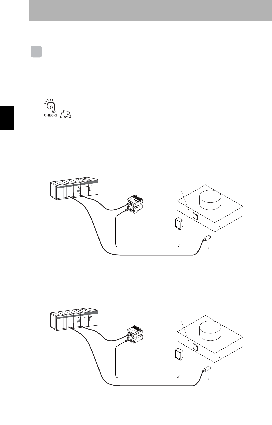
System Configuration
The DeviceNet Remote ID Controller conforms to the open network DeviceNet and enables simple connection
for slaves using special connectors. One-touch connectors on the Amplifier and Antenna improve usability.
Also, any of the V680-series ID Tags can be used.
Master Unit
Slave I/O I/O
Master Unit
V680-HAM42-DRT
Special Cable
DCA1/DCA2-5C10
Connector
Wireless communications
V680-HS51 V680-HS52 V680-HS63 V680-HS65
V680-D1KP52MT V680-D1KP66T V680-D1KP66MT V680-D1KP66T-SP
V680-D2KF52M V680-D2KF67 V680-D2KF67M V680-D8KF68/
-D32KF68
DeviceNet Remote ID Controller
DeviceNet Remote Master Unit
Antennas
ID Tags

15
RFID System
User's Manual
Section 1 Application Flowchart
Section 1
Product Overview
Application Flowchart
Preparation
Communications
Install the system.
Connect the system.
Perform actual communications using commands.
p.36
p.38
p.53

16
Section 1 Application Flowchart
RFID System
User's Manual
Section 1
Product Overview

Section 2 Names and Functions of Components
17
RFID System
User's Manual
Section 2
Names and Functions of Components
ID Controller 18
Antennas 22
ID Tags 23
18
Section 2 ID Controller
RFID System
User's Manual
Section 2
Names and Functions of Components
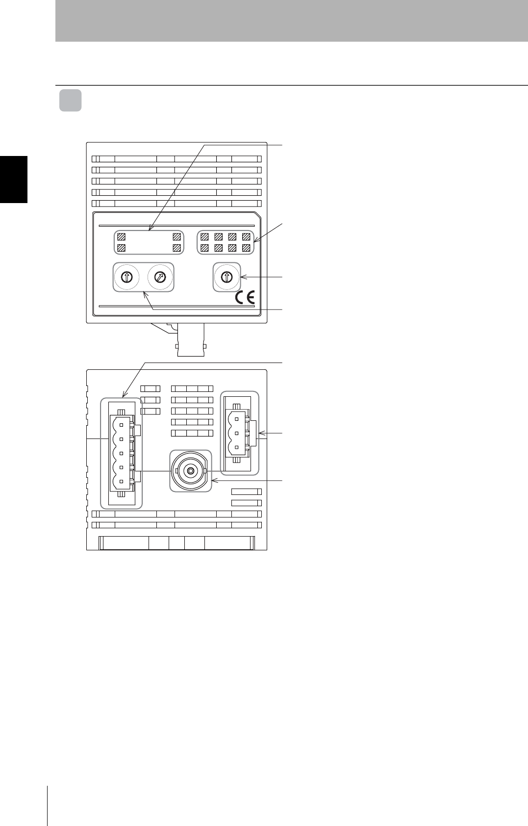
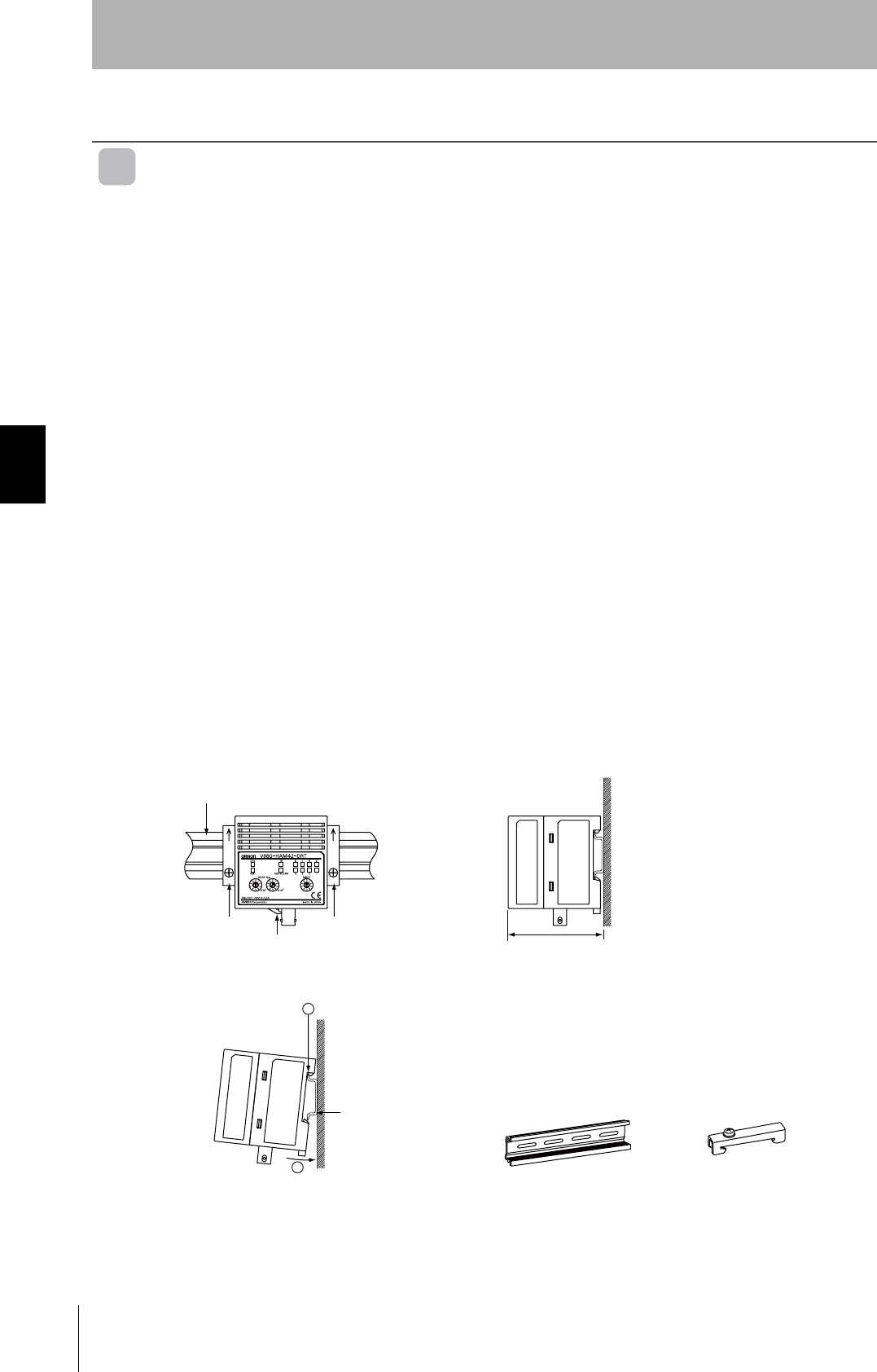
ID Controller
Part Names
OFF
FSM RFID
㪇
㪐
㪏
㪎
㪍
㪌
㪋
㪊
㪉
㪈
㪇
㪐
㪏
㪎
㪍
㪌
㪋
㪊
㪉
㪈
㪇
㪐
㪏
㪎
㪍
㪌
㪋
㪊
㪉
㪈
V680-HAM42-DRT
OMRON
OMRON Corporation
SOURCE : 24VDC 0.3A
MADE IN JAPAN
X10
1
X10
0
DEV
RMT
TR
NORM/ERR
8
4
7
3
6
2
5
1
NODE No. MODE
Operation Indicators
MS: Unit status
NS: Network status
TR: ID Tag communications status
NORM/ERR: Result of communications with ID Tag
Data/Error Code Indicators (Two-color)
Data (green)
Error code (red)
Mode Switch
Remote ID Controller operating mode setting switch
Node Address Switches
Node address switches (00 to 63)
DeviceNet Connector
Connects to DeviceNet Remote Master Unit.
Power Supply Terminals
Connect to 24-VDC power.
Recommended Power Supply: S8VS-03024
Antenna Connector
Connects to V680-series Antenna (V680-H@@).

19
RFID System
User's Manual
Section 2 ID Controller
Section 2
Names and Functions of Components
Functions
Operation Indicators
MS Indicator (Machine Status)
The MS indicator shows the Controller status.
NS Indicator (Network Status)
The NS indicator shows the network status.
TR Indicator
The TR indicator shows the ID Tag communications status.
NORM/ERR Indicator
The NORM/ERR indicator shows the result of communications with ID Tags.
Data/Error Code Indicators
These indicators show the first byte of data that was read or written when communications ends
normally. They also show the error code if communications end in an error.
Status Definition
Lit green Normal
Flashing green Settings not made.
Lit red Fatal error
Flashing red Non-fatal error
Not lit No power
Status Definition
Lit green Communications connected.
Flashing green Communications not connected.
Lit red Fatal communications error
Flashing red Non-fatal communications error
Not lit No power
Status Definition
Lit yellow ID Tag is communicating.
Flashing yellow ID Tag is communicating.
Not lit Standby
Status Definition
Lit green Normal end
Lit red Error end
Not lit Standby
Status Definition
Lit green Data displayed.
Lit red Error code displayed.
Not lit Standby
20
Section 2 ID Controller
RFID System
User's Manual
Section 2
Names and Functions of Components
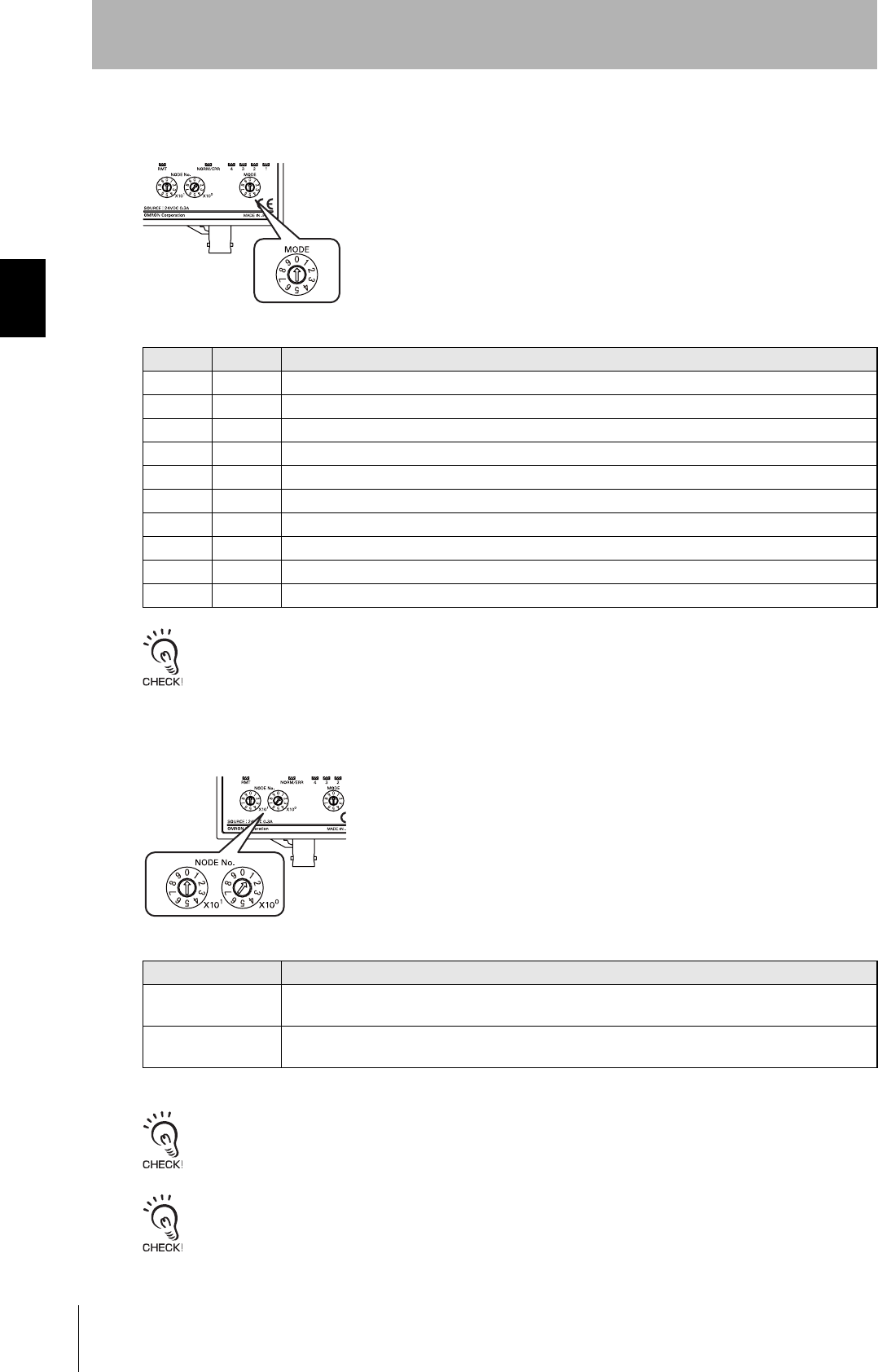
Mode Switch
The mode switch sets the DeviceNet Remote ID Controller’s operating mode.
Turn the power OFF before setting the mode switch. The mode that is set when the power is turned ON will be used.
Node Address Switches
The node address switches set the node address of the DeviceNet Remote ID Controller.
Node addresses between 64 and 99 can be set using the Configurator. Refer to the DeviceNet DRT2-series Slave
Manual (Cat. No. ntlp) for information on the setting procedure.
Turn the power OFF before setting the node address switches. The node address that is set when the power is turned
ON will be used.
Mode Symbol Description
0 4CH 4-byte access mode
1 16CH 26-byte access mode
2 32CH 58-byte access mode
3 SYNC1 V600-compatible Trigger Mode, 100-ms output time
4 SYNC2 V600-compatible Trigger Mode, 500-ms output time
5 AUTO1 V600-compatible Auto Mode, 100-ms output time
6 AUTO2 V600-compatible Auto Mode, 500-ms output time
7 TEST Test mode (checking operation alone)
8 NOISE Noise measurement mode (measuring the noise environment around the Antenna)
9 - Mode setting error
Item Description
Setting method Two-digit decimal number
The left rotary switch sets the 10s digit, and the right rotary switch set the 1s digit.
Setting range 00 to 63
The default setting is 00.
21
RFID System
User's Manual
Section 2 ID Controller
Section 2
Names and Functions of Components
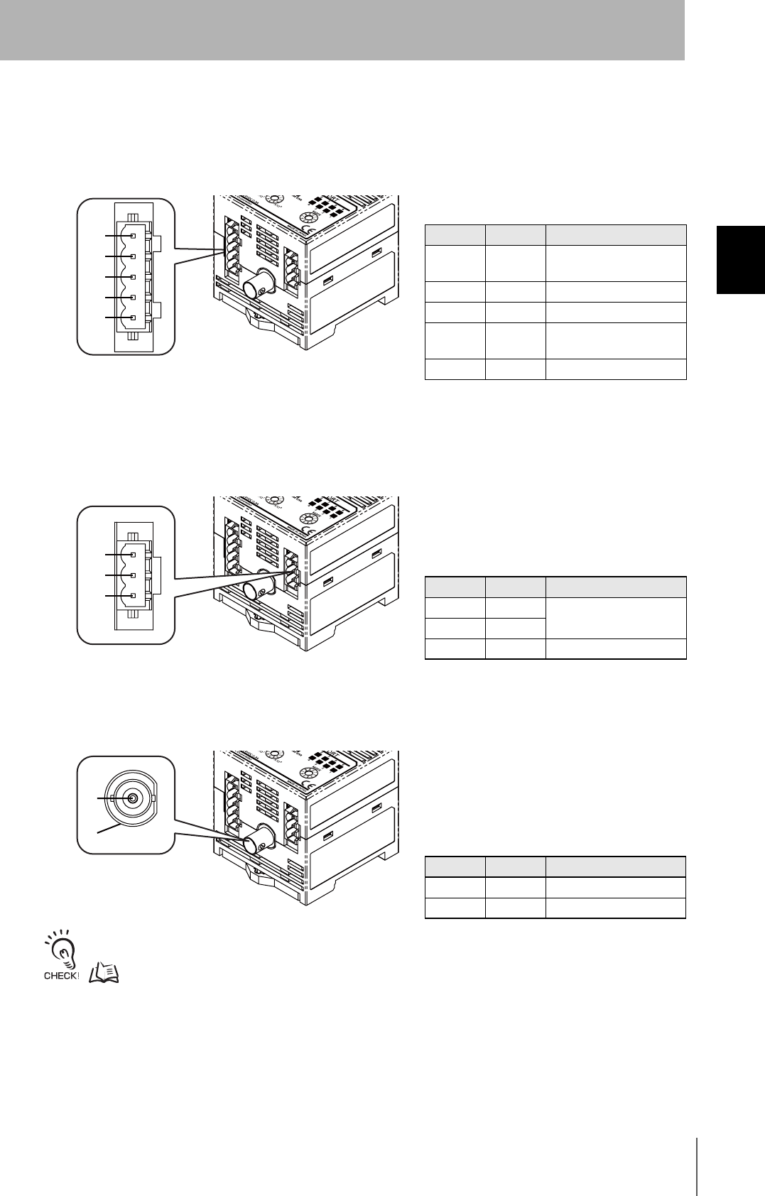
DeviceNet Connector
The DeviceNet connector port connects the DeviceNet Remote ID Controller to the Master Unit. Use
the enclosed connector.
Enclosed connector model: FKC2.5/5-ST-5.08-RFAUM (Phoenix Contact)
Power Supply and Ground Connector
The power supply terminals supply 24-VDC power using the enclosed connector.
Enclosed connector model: FKC2.5/3-ST-5.08-RF (Phoenix Contact)
Antenna Connector
Connect this connector to the V680-series Antenna (V680-H@@).
Refer to System Configuration in Section 1 Product Overview for information on the Antennas that can be connected.
p.14
Pin No. Name Signal type
1 V- Power supply negative
side
2 CAN_L Low communications data
3 Drain Shield
4 CAN_H High communications
data
5 V+ Power supply positive side
Pin No. Name Function
1 +V 24-VDC input terminals
2-V
3 GR Ground terminal
Pin No. Name Signal type
1 S Signal line
2 GND Analog ground
5
4
3
2
1
3
2
1
2
1
22
Section 2 Antennas
RFID System
User's Manual
Section 2
Names and Functions of Components
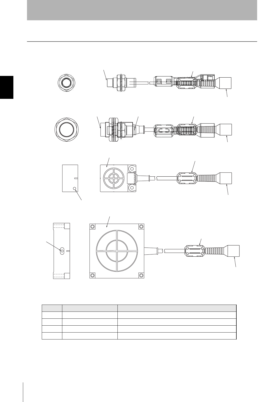
Antennas
No. Name Description
1 Operation indicator Lights when a signal is transmitted.
2 Communications surface Mounted facing the ID Tags.
3 Ferrite core Attenuates noise from the ID Tags.
4 Connector Connects to the ID Controller.
(2) Communications surface
(2) Communications
sufrace
(2) Communications surface
(2) Communications surface
(3) Ferrite core
(3) Ferrite core
(3) Ferrite core
(3) Ferrite core
(1) Operation indicator
(1) Operation indicator
(1) Operation
indicator
(4) Connector
(4) Connector
(4) Connector
(4) Connector

23
RFID System
User's Manual
Section 2 ID Tags
Section 2
Names and Functions of Components
ID Tags
The ID Controller communications with the ID Tags through the Antenna to read and write data in the
internal memory of the ID Tags.
The printed side is the communications surface. Mount the ID Tags with the communications surfaces
facing the Antenna.

24
Section 2 ID Tags
RFID System
User's Manual
Section 2
Names and Functions of Components
MEMO

Section 3 Functions and Operation
25
RFID System
User's Manual
Section 3
Functions and Operation
ID Controller 26
ID Tags 31
26
Section 3 ID Controller
RFID System
User's Manual
Section 3
Functions and Operation
ID Controller
Communications with ID Tags
With the DeviceNet Remote ID Controller, the operating mode is set on the mode switch and the
command is selected to communicate with the ID Tags.
Operating Mode
There are four operating modes.
For the mode settings, refer to Names and Functions of Components in Section 2.
p.17
Trigger Mode
When the ID Tag on a workpiece or palette moves within the communications range of the Antenna, it
is detected by a sensor or a switch. A control signal (trigger signal) is output from the PLC to the
DeviceNet Remote ID Controller, which triggers the DeviceNet Remote ID Controller to begin
communications with the ID Tag. The DeviceNet Remote ID Controller reads the Tag data and outputs
the results to the PLC.
Auto Mode
When the ID Tag of a workpiece or palette is within the communications range of the Antenna, the
Remote ID Controller automatically begins communications with the ID Tag and outputs the result to
the PLC.
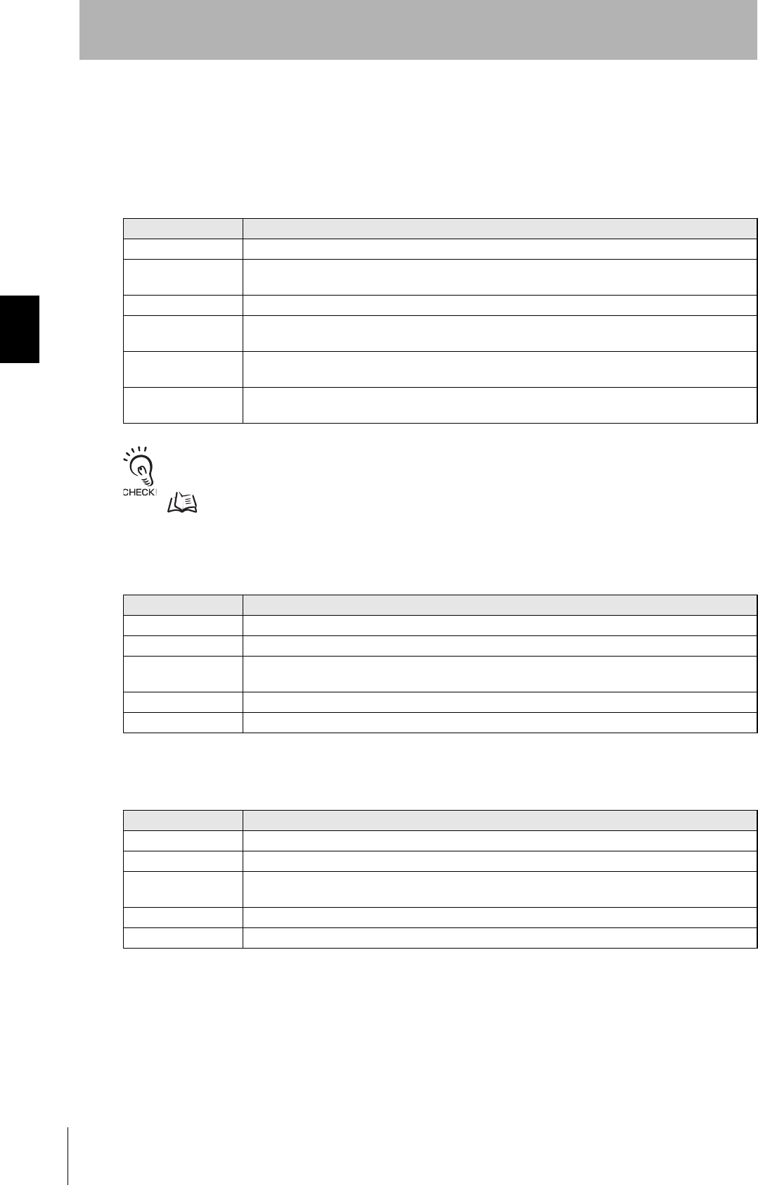
Master Unit
DeviceNet Remote ID
V680-HAM42-DRT
Antenna
Sensor or Switch
Palette, etc.
ID Tag
Master Unit
DeviceNet Remote ID
V680-HAM42-DRT
Antenna
Sensor or Switch
Palette, etc.
ID Tag

27
RFID System
User's Manual
Section 3 ID Controller
Section 3
Functions and Operation
Test Mode
During system installation or maintenance, the mode switch can be set to 7 (Test Mode) to read ID Tag
data when the power supply is turned ON. The communications results are display on the operation
indicators and the data/error code indicators.
Noise Measurement Mode
If communications with the ID Tags is unstable, set the mode switch to 8 (Noise Measurement Mode).
When the power supply is turned ON, the noise around the Antenna will be measured, and the data will
be shown on the indicators.
Refer to Noise Measurement in this section for information on measuring noise.
p.30
28
Section 3 ID Controller
RFID System
User's Manual
Section 3
Functions and Operation
Commands
Communications with the ID Tag is controlled by commands allocated to the DeviceNet Remote ID
Controller signals.
Using 4-byte, 26-byte, and 56-byte Access Modes
The commands given in the following table can be used if the mode switch is set to 0 to 2.
Noise measurement is not a command used for communications with ID Tag, but a command used for maintenance.
Refer to Noise Measurement for details.
p.30
Using V600-compatible Sync Modes 1 and 2
The commands given in the following table can be used if the mode switch is set to 3 to 4.
Using V600-compatible Auto Modes 1 and 2
The commands given in the following table can be used if the mode switch is set to 4 to 5.
Command Explanation
READ Data in the ID Tag memory is read by specifying the number of bytes to process.
WRITE Data is written to the ID Tag by specifying the memory address, number of bytes to process, and the
data.
BIT SET Bits in the ID Tag memory are set by specifying the memory address and number of bytes to process.
BIT CLEAR Bits in the ID Tag memory are cleared by specifying the memory address and number of bytes to
process.
DATA FILL Based on the specified address, number of blocks to process, and data, the specified memory area of
the ID Tag is filled with the same data.
NOISE
MEASUREMENT
The strength of noise affecting the Antenna is measured.
Command Explanation
READ/WRITE Switches between the WRITE command and the READ command.
BYTE/BIT WRITE Switches between the BYTE WRITE command and the BIT WRITE command.
BIT SET/CLEAR Switches between the BIT SET and the BIT CLEAR command when the BIT WRITE command is
used.
WRITE BYTES Switches the number of bytes to be written.
WRITE AREA Switches the address where writing will be performed.
29
RFID System
User's Manual
Section 3 ID Controller
Section 3
Functions and Operation
Options
The following functions can be used with the DeviceNet Remote ID Controller by setting the control
signal options.
Using 4-byte, 26-byte, and 56-byte Access Modes
The functions given in the following table can be used if the mode switch is set to 0 to 2.
Using V600-compatible Sync Modes 1 and 2
The functions given in the following table can be used if the mode switch is set to 3 or 4.
Using V600-compatible Auto Modes 1 and 2
The functions given in the following table can be used if the mode switch is set to 5 or 6.
Function Explanation
Communications Speed The communications time required for writing large amounts of data to the ID Tag using
the DATA FILL command can be reduced by setting the communications speed to high.
Be aware that the noise resistance may be lower during communications when this
function is being used.
For details on the communications time, refer to Communications Time (Reference).
p.101
Verification Select whether to enable or disable the verification function.
Write Protection Important data stored in the memory of an ID Tag, such as the product model or type, can
be protected from being overwritten inadvertently by enabling the Write Protection
function.
Refer to Write Protection for details.
p.32
Output Time When Auto Mode is being used, the result output time can be set to either 100 ms or
500 ms.
Refer to I/O Settings and Control Methods for details on the output timing.
p.61
Host Communications Mode Trigger Mode or Auto Mode can be selected as the method for the communications with
the PLC.
Read/Write Data Code The number of bytes that can be accessed can be increased by converting the read/write
data code from ASCII to hexadecimal if the data code in the ID Tag is ASCII.
Function Explanation
Output Time When Auto Mode is being used, the result output time can be set to either 100 or 500 ms.
Refer to I/O Settings and Control Methods for details on output timing.
p.61
Host Communications Mode Trigger Mode or Auto Mode can be selected as the method for the communications with
the PLC.
Function Explanation
Output Time When Auto Mode is being used, the result output time can be set to either 100 or 500 ms.
Refer to I/O Settings and Control Methods for details on output timing.
p.61
Host Communications Mode Trigger Mode or Auto Mode can be selected as the method for the communications
procedure with the PLC.

30
Section 3 ID Controller
RFID System
User's Manual
Section 3
Functions and Operation
Noise Measurement
You can check whether noise that affects communications with ID Tags exists in the area where the
Antenna and ID Controller are installed.
When a noise measurement command is sent from the PLC, the noise strength received by the
Antenna is output in a value from 00 to 99.
The measured noise strength is also displayed in four levels on the data indicators, and so it can be
checked directly on the DeviceNet Remote ID Controller.
Refer to NOISE MEASUREMENT for details of the noise measurement command.
p.58
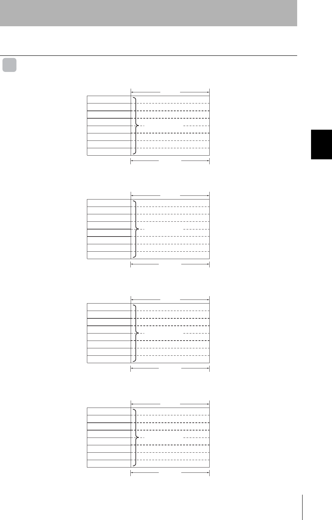
Relation between Result Output and Data Indicators
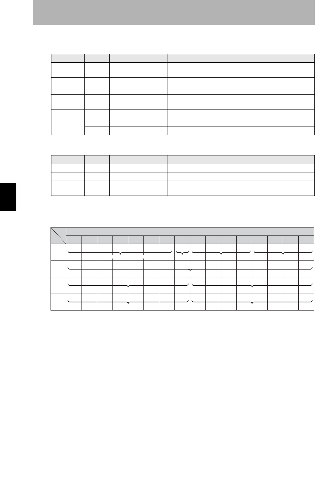
Example of Results Output and Influence on Communications Distance
Figure
Result output Data indicator status Result output Data indicator status
00 to 09 10 to 19
20 to 29 30 to 39
40 to 99
7654
3210
7654
3210
7654
3210
7654
3210
7654
3210 : OFF : ON
31
RFID System
User's Manual
Section 3 ID Tags
Section 3
Functions and Operation
ID Tags
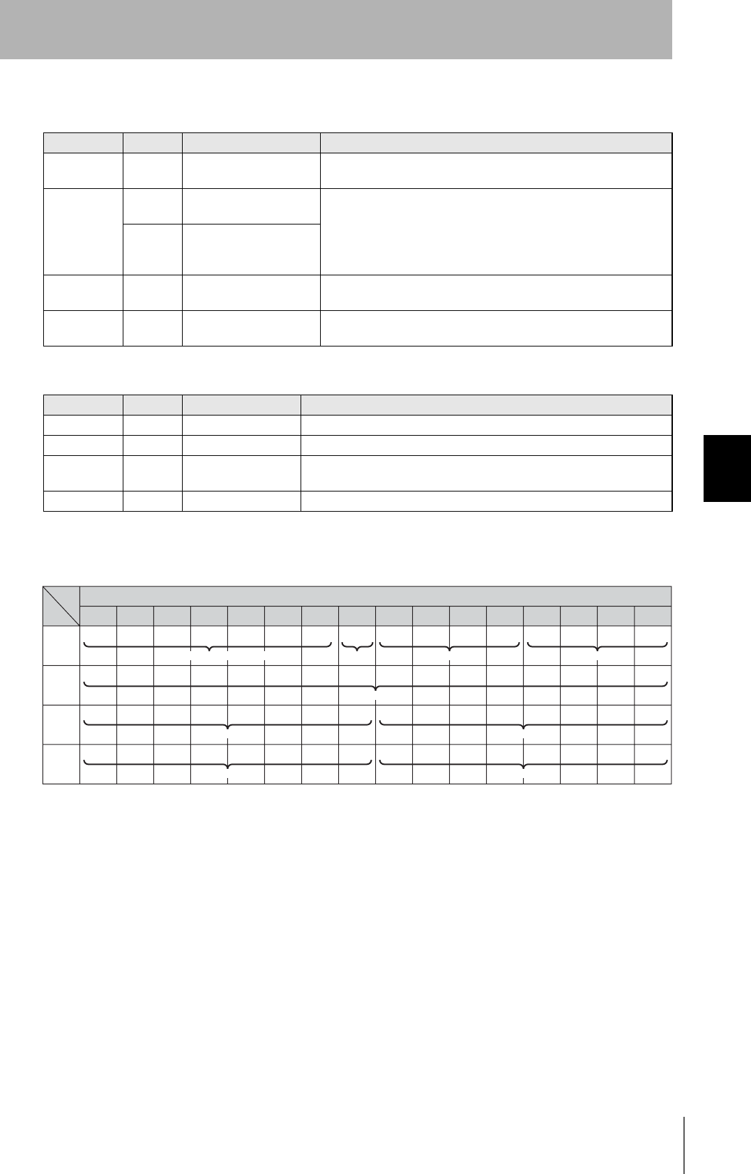
ID Tag Memory Map
V680-D1KP@@
V680-D2KF@@
V680-D8KF@@
V680-D32KF@@
Address (hex) Data
User area
1 byte
0000
0001
0002
0003
03E6
03E7
.
.
.
.
Address (hex) Data
User area
1 byte
0000
0001
0002
0003
07CEH
07CFH
.
.
.
.
Address (hex) Data
User area
1 byte
0000
0001
0002
0003
1FFE
1FFF
.
.
.
.
Address (hex) Data
User area
1 byte
0000
0001
0002
0003
7FFE
7FFF
.
.
.
.
32
Section 3 ID Tags
RFID System
User's Manual
Section 3
Functions and Operation
Write Protection
The write protection function protects important data stored in the memory of a ID Tag, such as the
product model or type, from being overwritten inadvertently.
Enable the write protection function after writing important data as described in this section.
Setting Write Protection
For the write protection function to be effective, it must be enabled or disabled in both the DeviceNet
Remote ID Controller settings and the ID Tag settings.
1. Enabling the Write Protection for the DeviceNet Remote ID Controller
The write protection function can be enabled or disabled by setting the write-protect bit of the DeviceNet Remote ID Controller in
the I/O Allocation Table.
Refer to the Signal Names and Functions for details.
p.49
2. Setting Write Protection in ID Tags
Write protection for individual ID Tags is set in the most significant bit of address 0000H.
Write protection is set in the 4 bytes from Tag address 0000H to 0003H.
• Write-protect bit (most significant bit of address 0000H)
1: Write-protected (Enable)
0: Not write-protected (Disable)
• Addresses in Tag Memory That Can Be Write Protected
Start address: 0000H to 7FFFH
End address: 0000H to FFFFH
The ID Tag write protection setting area (addresses 0000 hex to 0003 hex) can be used as user memory if the write
protection function is not used. To use the ID Tag’s write protection setting area (addresses 0000 hex to 0003 hex) as
user memory, be sure to disable write protection by setting the Write Protect Bit in the DeviceNet Remote ID Controller.
Address Bit 7 6 5 4 3 2 1 0
0000H Enable/disable Upper two digits of start address (00 to 7F)
0001H Lower two digits of start address (00 to 7F)
0002H Upper two digits of end address (00 to 7F)
0003H Lower two digits of end address (00 to 7F)
33
RFID System
User's Manual
Section 3 ID Tags
Section 3
Functions and Operation
Example of Write Protection
Start Address Is Lower Than the End Address
The memory area between the start address and end address will be write-protected.
Start Address Is Equal to End Address
Only the selected address (one byte) will be write-protected.
End Address Is Higher than the Last ID Tag Address
The memory area between the start address and the last ID Tag address will be write-protected.
Write-protected
0000H
0015H
0120H
03E7H
Address Bit Upper digits Lower digits
0000H 10000000
80
0001H 00010101
15
0002H 00000001
01
0003H 00100000
20
Write-protected
0000H
0021H
03E7H
Address Bit Upper digits Lower digits
0000H 10000000
80
0001H 00100001
21
0002H 00000000
00
0003H 00100001
21
Write-protected
0000H
0300H
03E7H
Address Bit Upper digits Lower digits
0000H 10000011
83
0001H 00000000
00
0002H 00000011
03
0003H 11111111
FF
34
Section 3 ID Tags
RFID System
User's Manual
Section 3
Functions and Operation
Start Address Is Higher Than End Address
The memory area between the start address and the last ID Tag address, as well as the area between
0004H and the end address will be write-protected.
Disabling Write Protection
Disabling Write Protection for Part of the ID Tags
Set the uppermost bit of 0000H to 0.
Disabling All Write Protection for the Whole RFID system
Set the Write Protection Enable Bit to 1 in the DeviceNet Remote ID Controller.
Caution When Using Write Protection
The write protect function is a DeviceNet Remote ID Controller function. It cannot be used with ID Controllers
manufactured by other companies.
Write-protected
0000H
0004H
0015H
03E7H
Write-protected
0120H
Last address
Start address
Address Bit Upper digits Lower digits
0000H 10000001
81
0001H 00100000
20
0002H 00000000
00
0003H 00010101
15

Section 4 Installation, Connections, and Wiring
35
RFID System
User's Manual
Section 4
Installation, Connections, and Wiring
DeviceNet Remote ID Controller 36
Installing Antennas 41
Installing ID Tags 44
36
Section 4 DeviceNet Remote ID Controller
RFID System
User's Manual
Section 4
Installation, Connections, and Wiring
DeviceNet Remote ID Controller
Installation
To ensure full functionality of the V680-HAM42-DRT DeviceNet Remote ID Controller, follow the
instructions provided in this section for installation.
Installation Site
Do not install the DeviceNet Remote ID Controller in the following locations.
•Locations exposed to ambient temperatures that are not between −10 and 55°C or where there are
radical temperature changes resulting in condensation
•Locations exposed to humidity that is not between 25% and 85%
•Locations subject to corrosive gas, flammable gas, dust, salt, or metal powder
•Locations that will expose the DeviceNet Remote ID Controller to direct vibration or shock
•Locations exposed to direct sunlight
•Locations exposed to spray of water, oil, or chemicals
•Locations more than 2,000 m above sea level
Mounting in a Panel
The DeviceNet Remote ID Controller can be used at an ambient temperature range of −10 to 55°C. Be
sure to observe the following precautions.
•Make sure that the Unit is provided with sufficient ventilation space.
•Do not install the Unit close to heaters, transformers, or large-capacity resistors that radiate
excessive heat.
Installation Method
Mounting to DIN Track
1. First hook the DeviceNet Remote ID Controller to part A, then press it in direction B to mount it to the
DIN Track.
2. To disconnect the DeviceNet Remote ID Controller from the DIN Track, pull the mounting hook
downwards, and then lift the Controller upwards.
DIN Track
End Plate
Mounting Hook
End Plate
65
OMRON PFP-100N2
(track length: 1 m)
is recommended.
DIN Track (recommended)
PFP-100N2
End Plate
PFP-M
A
B
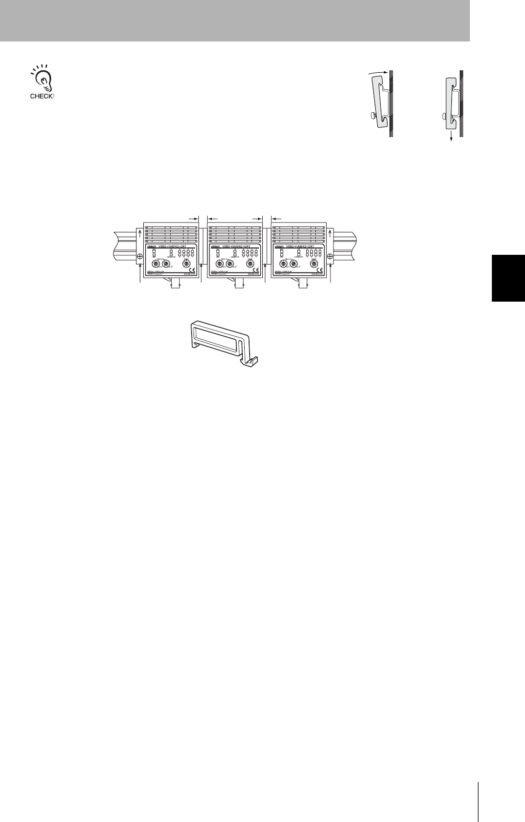
37
RFID System
User's Manual
Section 4 DeviceNet Remote ID Controller
Section 4
Installation, Connections, and Wiring
Attaching the End Plates
To mount an End Plate easily, first hook the bottom of the End Plate and then hook
the top on the DIN Track, pull the End Plate downwards and tighten the screw.
Recommended tightening torque: 1.2 N·m.
Mounting Interval
The V680-HAM42-DRT DeviceNet Remote ID Controllers will generate heat if they are mounted side-
by-side. Leave space between the Controllers of at least 10 mm.
Use at least 2 OMRON DIN Track Spacers. (Each Spacer is 5 mm wide.)
10 mm min.
10 mm min.
Spacer Spacer End Plate
End Plate
Spacer
PFP-S
38
Section 4 DeviceNet Remote ID Controller
RFID System
User's Manual
Section 4
Installation, Connections, and Wiring
Connection and Wiring
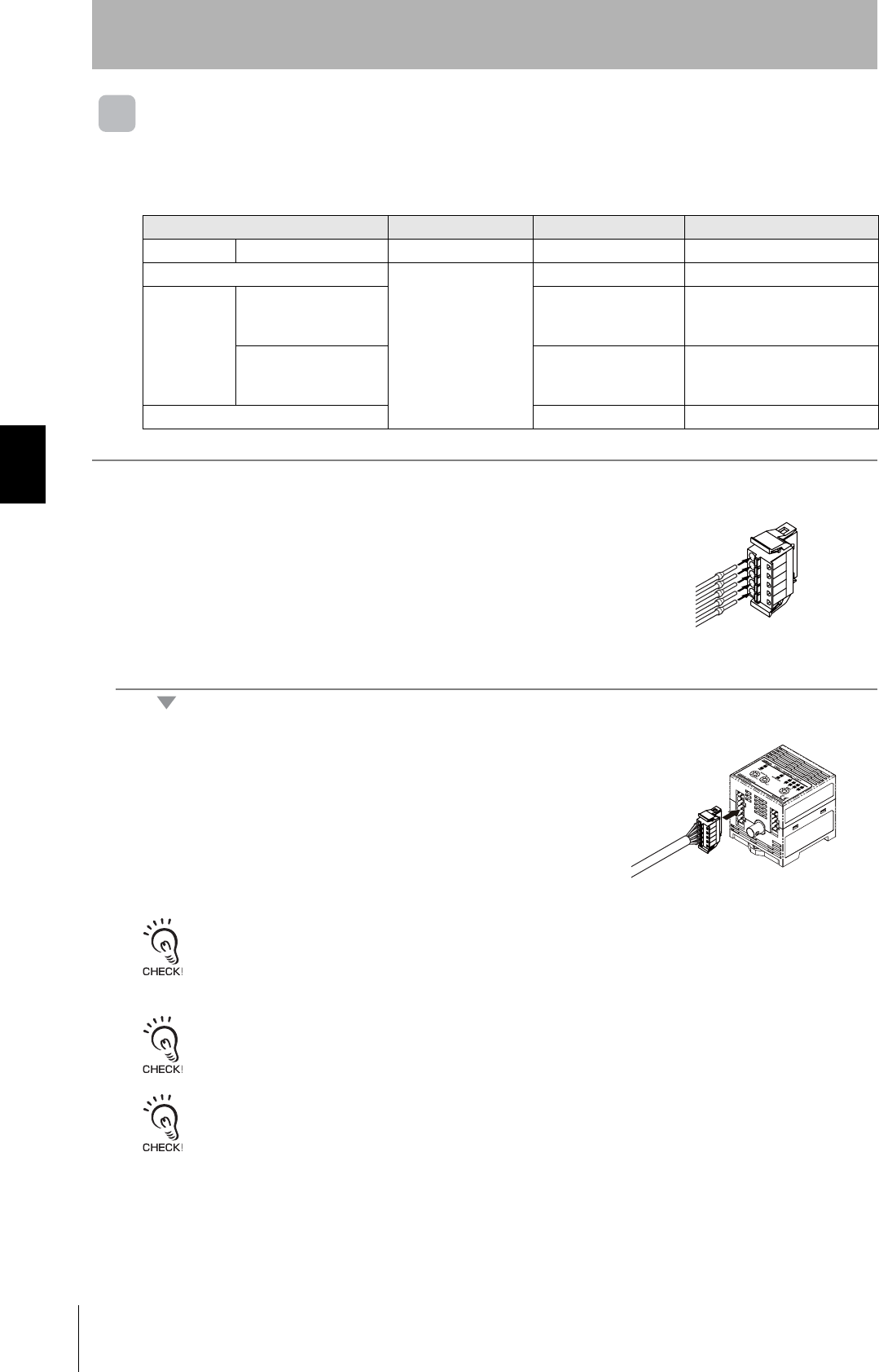
DeviceNet Remote Connector
Use the connector that comes with the Unit. You must provide the connecting cable.
1. Attach the crimp terminals to the sections of the cable where the
sheath has been stripped.
2. Make sure the connector is facing the right direction and insert
each crimp terminal into the correct connector hole.
3. Once all of the cables have been connected to the connector,
attach the connector to the DeviceNet Remote ID Controller.
Align the cable connector with the connector on the DeviceNet Remote ID
Controller. Hold the connector body and push the connector firmly into place.
Removing the Connector
Remove the connector by pressing in on the lock on the cable connector to release the lock and pulling the connector
straight out. If the connector is difficult to remove, press on the DeviceNet Remote ID Controller while pulling on the
connector.
Do not connect cables to the connector after attaching the connector to the DeviceNet Remote ID Controller.
Use the recommended Power Supply (S8VS-03024, OMRON).
Brand Model Note
Cable Power line --- --- 1.0 mm2 (equivalent to AWG18)
Connector
Phoenix Contact
FKC2.5/5ST5.08RFAUM ---
Crimp
Terminal
When one line is
connected to one
terminal
AI1-10RD
---
When two lines are
connected to one
terminal
AI-TWIN2 × 1-10RD
---
Crimping Tool CRIMPFOX UD6 ---
39
RFID System
User's Manual
Section 4 DeviceNet Remote ID Controller
Section 4
Installation, Connections, and Wiring
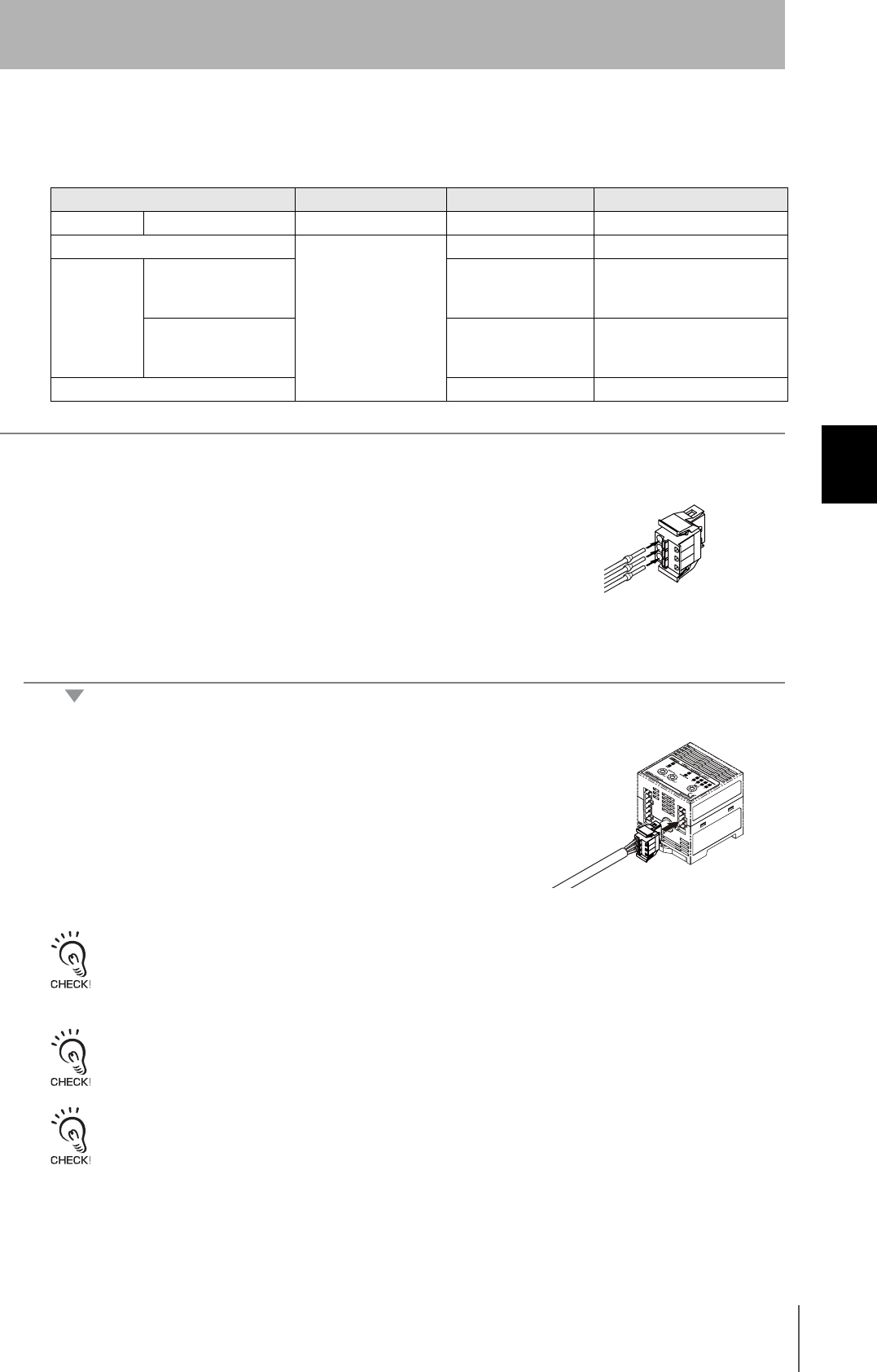
Power Supply Connector
Use the enclosed connector. The user must provide the cable.
1. Attach the crimp terminals to the sections of the cable where the
sheath has been stripped.
2. Make sure the connector is facing the right direction and insert
each crimp terminal into the correct connector hole.
3. Once all of the cables have been connected to the connector,
attach the connector to the DeviceNet Remote ID Controller.
Align the cable connector with the connector on the DeviceNet Remote ID
Controller. Hold the connector body and push the connector firmly into place.
Removing the Connector
Remove the connector by pressing in on the lock on the cable connector to release the lock and pulling the connector
straight out. If the connector is difficult to remove, press on the DeviceNet Remote ID Controller while pulling on the
connector.
Do not connect cables to the connector after attaching the connector to the DeviceNet Remote ID Controller.
Use the recommended Power Supply (S8VS-03024, OMRON).
Brand Model Note
Cable Power line --- --- 1.0 mm2 (equivalent to AWG18)
Connector
Phoenix Contact
FKC2.5/3-ST-5.08-RF ---
Crimp
Terminal
When one line is
connected to one
terminal
AI1-10RD
---
When two lines are
connected to one
terminal
AI-TWIN2 × 1-10RD
---
Crimping Tool CRIMPFOX UD6 ---
40
Section 4 DeviceNet Remote ID Controller
RFID System
User's Manual
Section 4
Installation, Connections, and Wiring
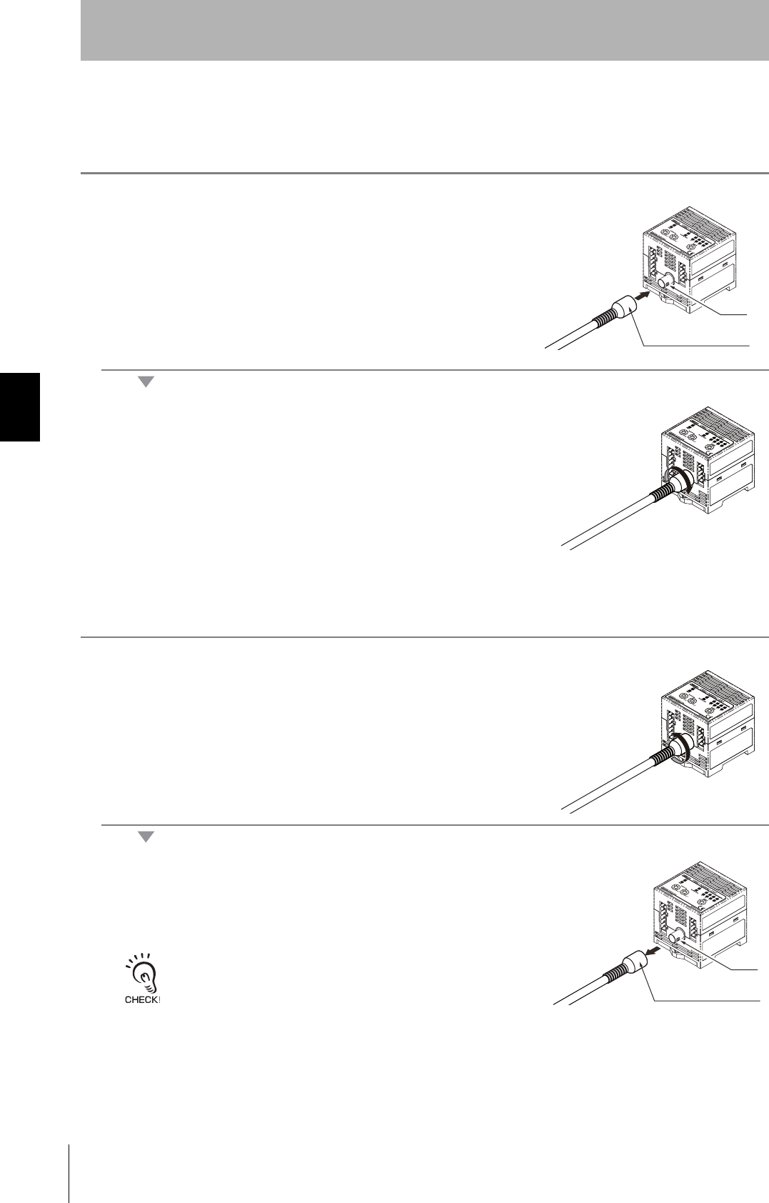
Antenna Connector
Mounting the Antenna
1. Hold the connector part of the Antenna and insert it into the
Antenna port while matching the key on the Unit with the groove
on the connector.
2. Turn the connector clockwise to lock it in place.
Removing the Antenna
1. Turn the connector in counterclockwise to release the lock.
2. Pull the connector straight out of the port.
The connector cannot be removed without turning it to release the lock.
If the cable is pulled without releasing the lock, it may cause the cable or
wires to break. Make sure that the lock is released before pulling out the
connector.
Key
Antenna connector
Key
Antenna connector
41
RFID System
User's Manual
Section 4 Installing Antennas
Section 4
Installation, Connections, and Wiring
Installing Antennas
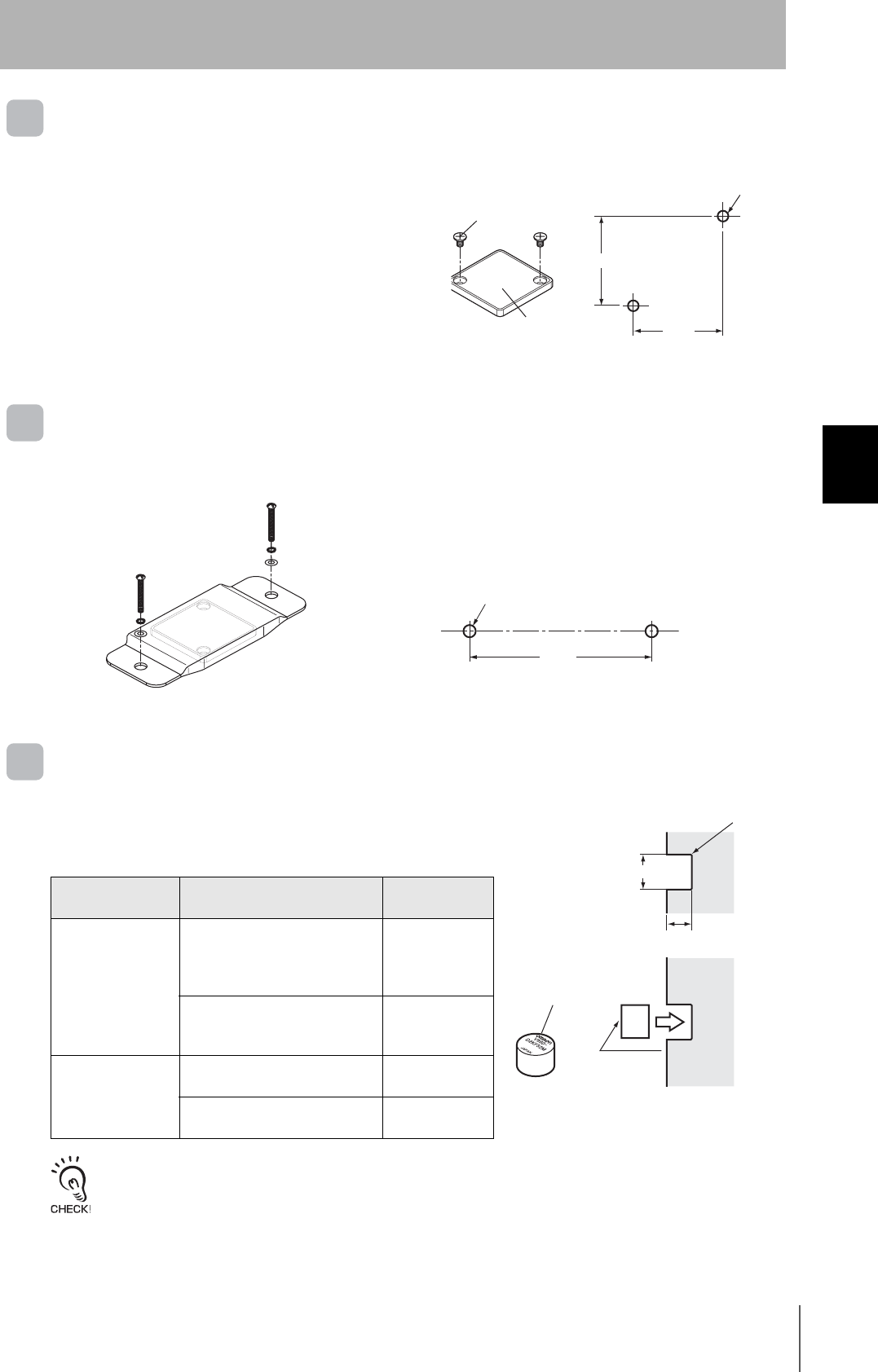
V680-HS51
Install the Antenna using the nuts and toothed washers that are provided on both sides of the mounting
material, as shown in the diagram below.
Securely tighten the screws to a maximum torque of 6 N·m.
V680-HS52
Install the Antenna using the nuts and toothed washers that are provided on both sides of the mounting
material, as shown in the diagram below.
When the Antenna is mounted to a metal object, the communications distance will be reduced by approximately 10%
compared with mounting to a non-metallic object. For details on the effect of metal surrounding the Antenna, refer to
Effect of Surrounding Metals on the Antenna (Reference).
102
Securely tighten the screws to a maximum torque of 40 N·m.
12 dia.
+0.5
0
Metallic material
Nut
Toothed washers
Antenna
22 dia.
+0.5
0
Non-metallic material
Nut
Toothed washers
Antenna
42
Section 4 Installing Antennas
RFID System
User's Manual
Section 4
Installation, Connections, and Wiring
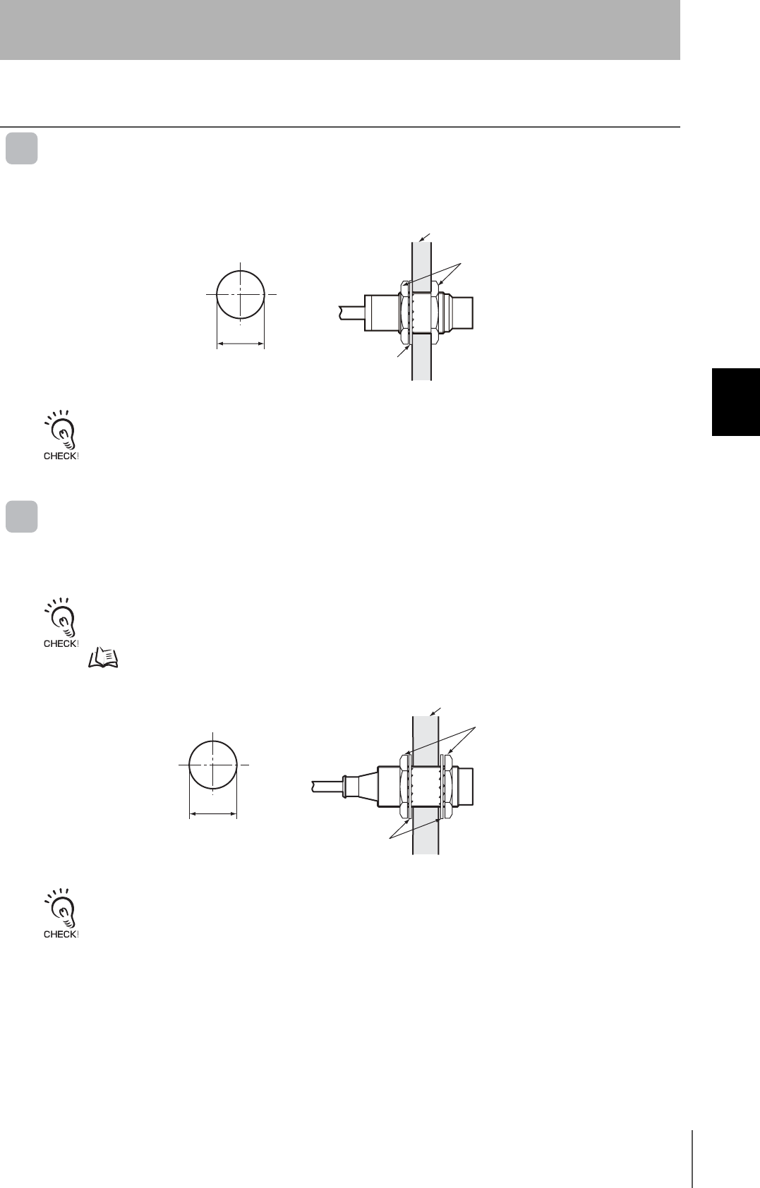
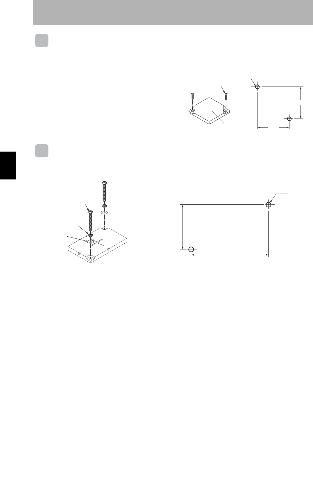
V680-HS63
Installation from the Front
Installation from the Back
Insert the nuts that come with the Antenna into sections A.
Securely tighten screws to a maximum torque of 1.2 N·m.
Coil center Two, M4
40
27
53
28±0.2
Coil center Two, M4
40
27
28
±0.2
Nut
43
RFID System
User's Manual
Section 4 Installing Antennas
Section 4
Installation, Connections, and Wiring
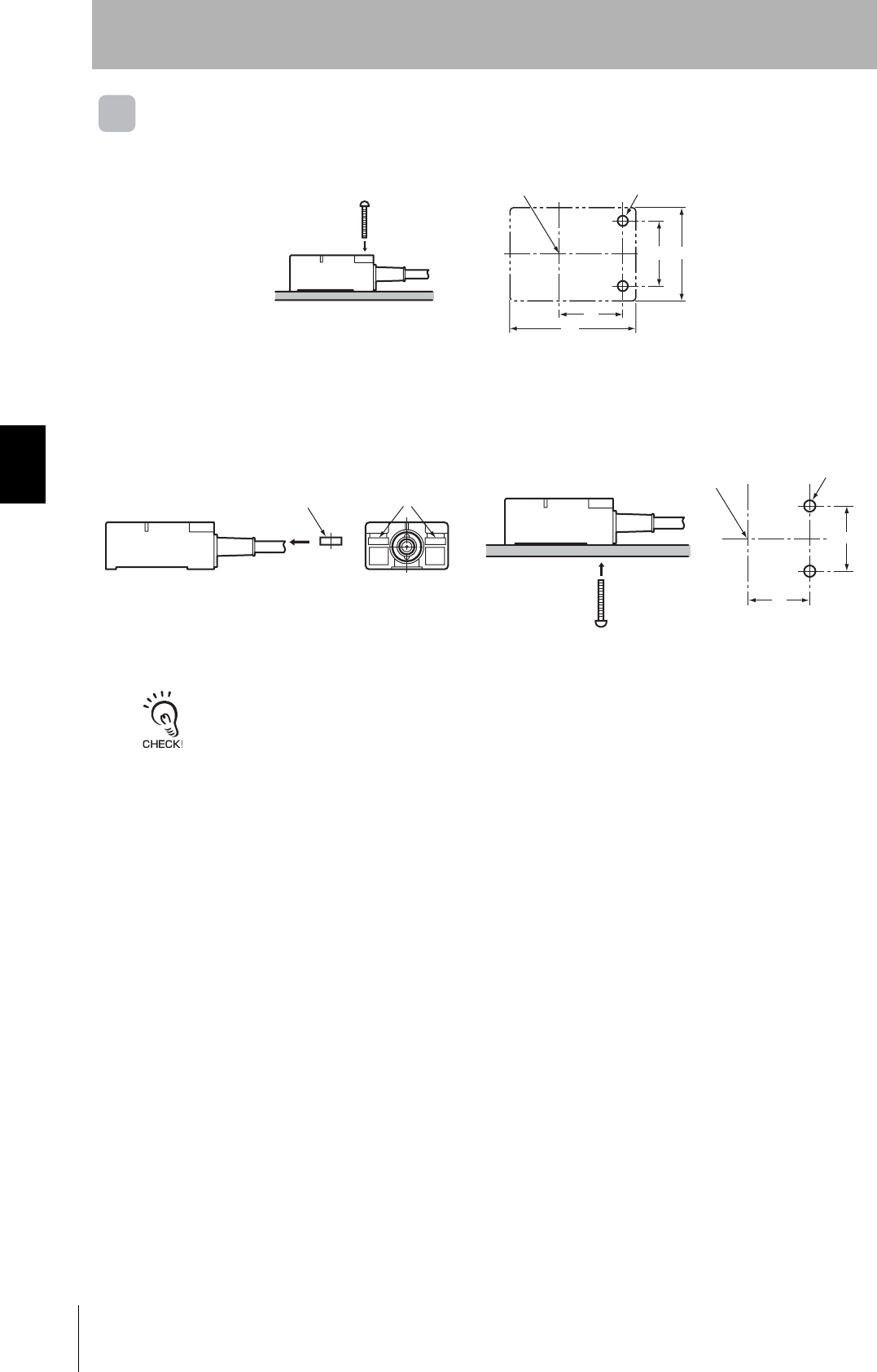
V680-HS65
Securely tighten screws to a torque of 0.7 to 1.2 N·m.
Mounting Bracket Dimensions (Provided Only with the V680-HS65)
Use M4 screws and spring washers (in four places) for
Antenna installation.
Tighten the screws to a torque of 0.7 to 1.2 N·m.
There are no restrictions on the mounting direction or
the direction of access to the Tag, but if the Antenna is to
be installed near a device such as a conveyance belt,
make sure there is no danger of the Antenna being
accidentally struck.
Note: When installing the Antenna, mount it on the
enclosed Mounting Bracket. The Mounting Bracket
is not necessary, however, if the Antenna is
mounted on a metal base that is larger than the
Antenna (100 × 100 mm).
Four, M4
90±0.2
90±0.2
100
100
Four, C1
90
±0.1
100
±0.2
100
±0.2
90
±0.1
Four, 4.5+0.3
0dia.
V680-HS65 Mounting base
Mounting Bracket
(provided)
44
Section 4 Installing ID Tags
RFID System
User's Manual
Section 4
Installation, Connections, and Wiring
Installing ID Tags
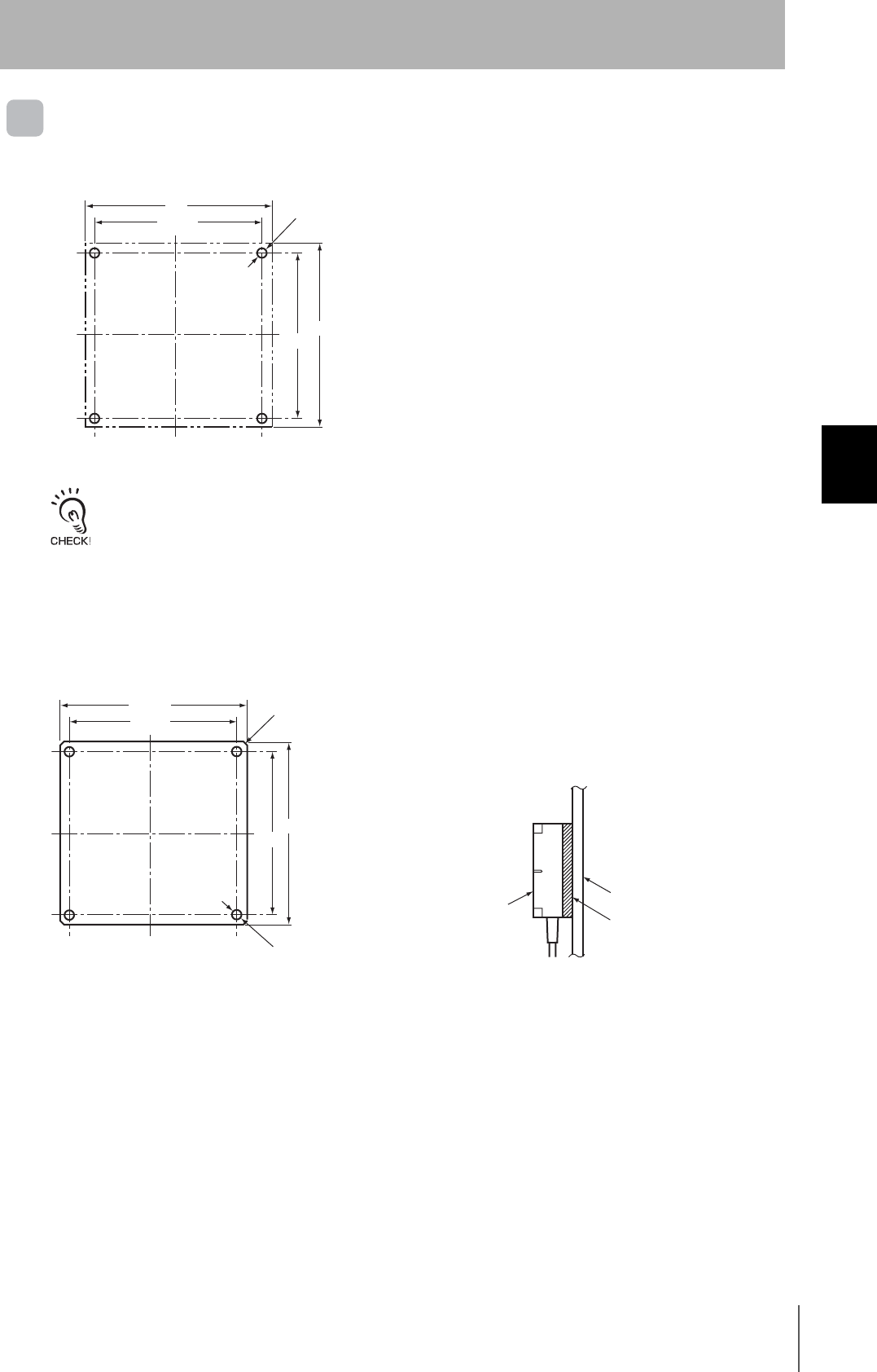
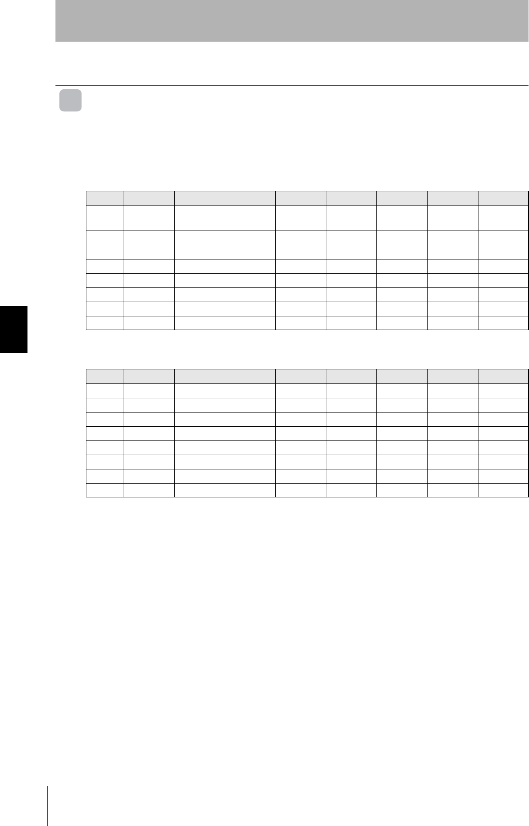
V680-D1KP52MT
Tag Installation
Mount Tags as shown in the diagram on the right. The epoxy
adhesives listed in the following table are recommended for the
given temperature ranges.
When embedding the V680-D1KP52MT into a metal surface, use the V680-HS51/-HS52 Antenna.
Transmission will not be possible if the V680-HS63 Antenna is used.
V680-D1KP66T
Mounting on Non-metallic Material
Mount the ID Tag using M3 pan-head screws from the
marked side.
Tightening torque: 0.3 to 0.5 N·m
Mounting on Metal
The communications distance will decrease if there is
metal at the back of the V680-D1KP66T ID Tag.
If the ID Tag is mounted to metal, use the separately
sold Special Attachment (V600-A86) or a non-metallic
spacer (e.g., plastic or resin).
Refer to Effect of Metal behind Tags (Reference) in Section 6 Appendices for information on the effect of metal behind
the V680-D1KP66T.
p.107
Ambient
operating
temperature
Product name Manufacturer
−40 to 70°C
Two-part Epoxy-compound Resin:
TB2001 (main agent)/TB2105C (curing agent)
Three Bond
Co., Ltd.
One-part Moisture-curing Elastic Adhesive
TB1530
Three Bond
Co., Ltd.
−40 to
150°C
One-part Epoxy Resin: TB2285 Three Bond
Co., Ltd.
Two-part Epoxy Resin: TB2087 Three Bond
Co., Ltd.
R0.2 max.
Marked side
Marked side
8.1+0.1
0dia.
5+0.1
0
Two, M3
Mounting Hole Dimensions
Marked side
25
±0.2
25
±0.2
M3 pan-head screw
Two, M3
Mounting Hole Dimensions
Marked
side
25
±0.2
25
±0.2
Attachment (V600-A86)
M3 pan-head screw
45
RFID System
User's Manual
Section 4 Installing ID Tags
Section 4
Installation, Connections, and Wiring
V680-D1KP66MT
Mount the ID Tag to metal using M3 pan-head screws
from the marked side. Tighten the screws to a torque
of 0.3 to 0.5 N·m.
V680-D1KP66T-SP
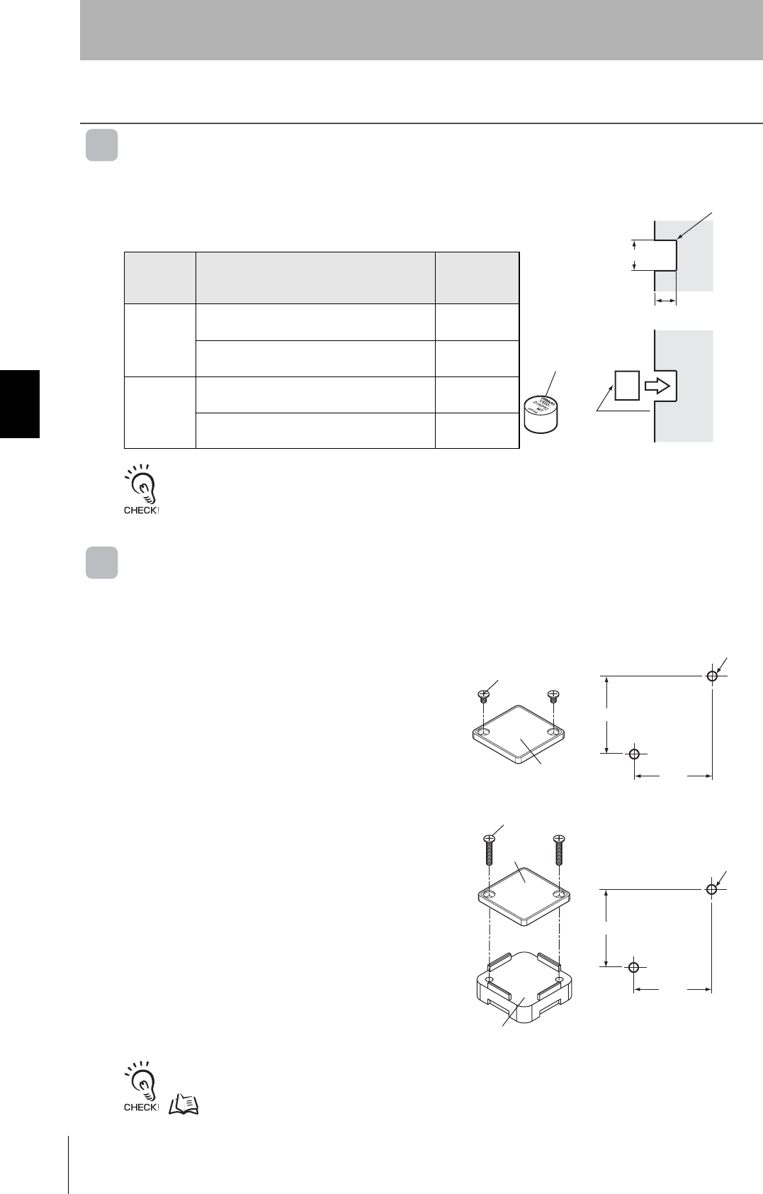
Mount the ID Tag using M5 screws and washers. Tighten the screws to a torque of 1.2 N·m or less. The
installation direction of ID Tags is not restricted by the travel direction in respect to the Antenna.
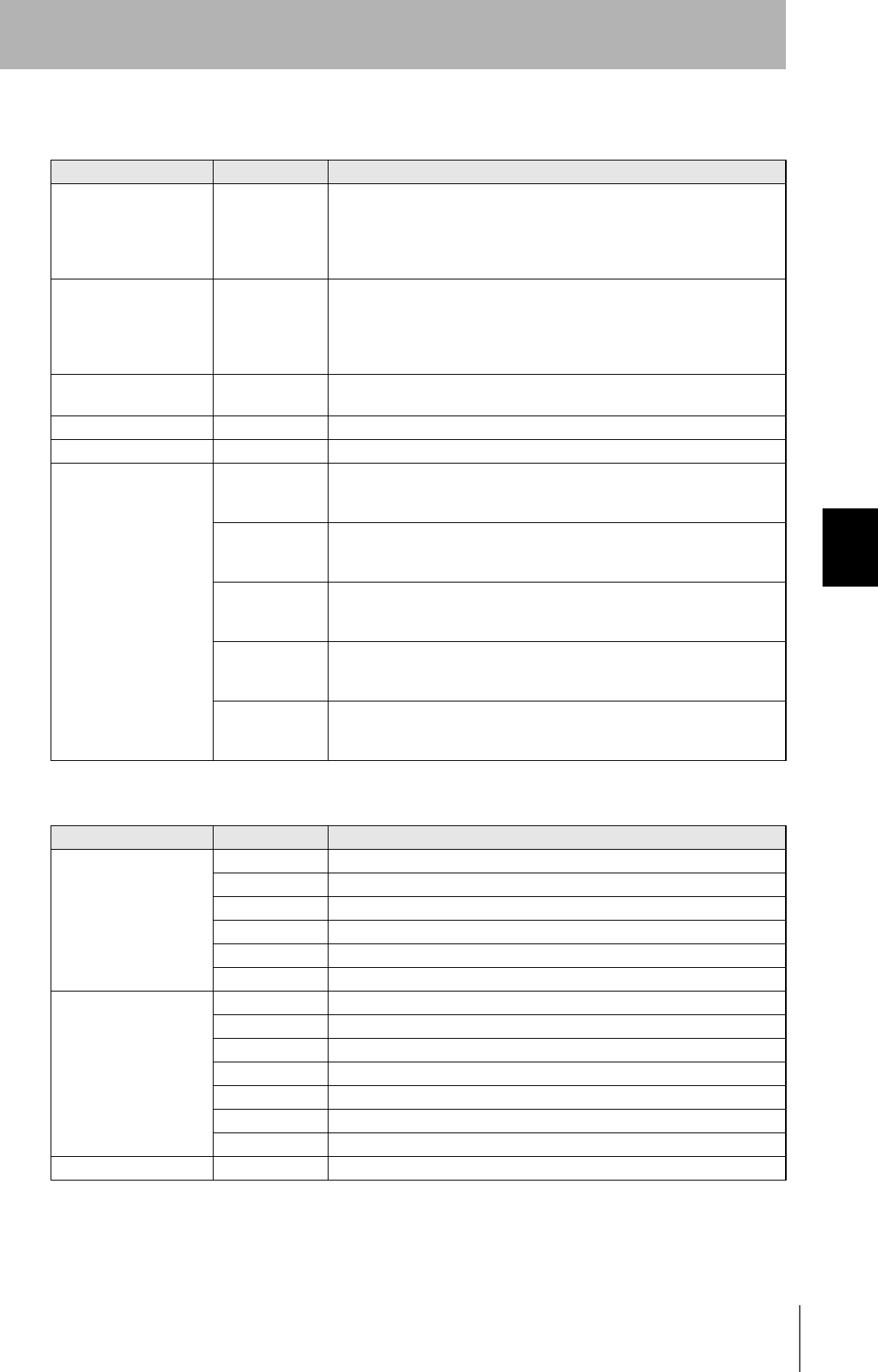
V680-D2KF52M
Tag Installation
Mount Tags as shown in the diagram on the right.
The epoxy adhesives listed in the following table are
recommended for the given temperature ranges.
When embedding the V680-D2KF52M into a metal surface, use the V680-HS51/HS-52 Antenna.
Transmission will not be possible if the V680-HS63 Antenna is used.
Ambient operating
temperature Product name Manufacturer
−40 to 70°C
Two-part Epoxy-compound
Resin:
TB2001 (main agent)/TB2105C
(curing agent)
Three Bond Co.,
Ltd.
One-part Moisture-curing Elastic
Adhesive
TB1530
Three Bond Co.,
Ltd.
−40 to 85°C
One-part Epoxy Resin: TB2285 Three Bond Co.,
Ltd.
Two-part Epoxy Resin: TB2087 Three Bond Co.,
Ltd.
Two, M3
Mounting Hole Dimensions
Marked
side
25±0.2
25±0.2
M
3 pan-head screw
Two, M5
Mounting Hole Dimensions
80
±0.2
R0.2 max.
Marked side
Marked side
8.1+0.1
0dia.
5+0.1
0
46
Section 4 Installing ID Tags
RFID System
User's Manual
Section 4
Installation, Connections, and Wiring
V680-D2KF67/-D2KF67M
Tag Installation
Secure the Tag with M3 screws. Tighten the screws
to a torque of 0.6 N·m or less.
V680-D8KF68/-D32KF68
Tag Installation
Secure the Tag with M4 screws. Tighten the screws to a torque of 0.7 to 1.2 N·m.
Two, M3
Mounting Hole Dimensions
Marked
side
32±0.2
32±0.2
M3 pan-head screw
Two, M4
Flat
washer
Spring
washer
M4 screw
44
76

Section 4 I/O Settings and Control Methods
47
RFID System
User's Manual
Section 5
I/O Settings and Control Methods
I/O Specifications 48
Timing Charts 61
48
Section 5 I/O Specifications
RFID System
User's Manual
Section 5
I/O Settings and Control Methods
I/O Specifications
I/O Allocation Table
Mode: 4-byte Access
The DeviceNet Remote ID Controller is allocated 64 inputs (4 words) and 64 outputs (4 words) in the
PLC. The inputs and outputs that are allocated (X words, Y words) depend on the node address set for
the Master and the DeviceNet Remote ID Controller.
Master Unit to Remote ID Controller
Remote ID Controller to Master Unit
Address Bit 7 Bit 6 Bit 5 Bit 4 Bit 3 Bit 2 Bit 1 Bit 0
X INHBIT/TRG AUTO/
SYNC
OUTPUTTIM
E
W
PROTECT
VERIFY HIGHSPD ASCII/HEX
(X+1) CMD3 CMD2 CMD1 CMD0 LEN3 LEN2 LEN1 LEN0
(X+2) ADDR7 ADDR6 ADDR5 ADDR4 ADDR3 ADDR2 ADDR1 ADDR0
(X+3) ADDR15 ADDR14 ADDR13 ADDR12 ADDR11 ADDR10 ADDR9 ADDR8
( X + 4 ) W-DATA W- DATA W- DATA W- DATA W-DATA W-DATA W- DATA W-DATA
( X + 5 ) W-DATA W- DATA W- DATA W- DATA W-DATA W-DATA W- DATA W-DATA
( X + 6 ) W-DATA W- DATA W- DATA W- DATA W-DATA W-DATA W- DATA W-DATA
( X + 7 ) W-DATA W- DATA W- DATA W- DATA W-DATA W-DATA W- DATA W-DATA
Address Bit 7 Bit 6 Bit 5 Bit 4 Bit 3 Bit 2 Bit 1 Bit 0
YBUSY RUN
(Y+1) ERROR NORM
(Y+2) SYS_ERR CMD_ERR
(Y+3) 7F_ERR 7E79_ERR 71_ERR 7D_ERR 7A_ERR 70_ERR 72_ERR
( Y + 4 ) R _ DATA R _ D ATA R _ DATA R _ DATA R _ D ATA R _ DATA R _ DATA R _ DATA
( Y + 5 ) R _ DATA R _ D ATA R _ DATA R _ DATA R _ D ATA R _ DATA R _ DATA R _ DATA
( Y + 6 ) R _ DATA R _ D ATA R _ DATA R _ DATA R _ D ATA R _ DATA R _ DATA R _ DATA
( Y + 7 ) R _ DATA R _ D ATA R _ DATA R _ DATA R _ D ATA R _ DATA R _ DATA R _ DATA
49
RFID System
User's Manual
Section 5 I/O Specifications
Section 5
I/O Settings and Control Methods
Signal Names and Functions
Master Unit to Remote ID Controller
Remote ID Controller to Master Unit
Category Symbol Meaning
Interface signal INHIBT/TRG Auto Mode: Functions as INHIBT.
0: No communications with ID Tag.
1: Communications with ID Tag.
Sync Mode: Functions as TRIG.
1: Communications with ID Tag.
Execution command CMD3 to CMD0 0000: DATA READ
0001: DATA WRITE
0010: BIT SET
0011: BIT CLEAR
0100: DATA FILE
Process address ADDR0 to
ADDR15
Specifies the process start address.
Process bits LEN0 to LEN7 Specifies the number of process bits.
Write/manipulate data W-DATA Stores the write data when writing is executed.
Option specifications HIGHSPD Communications Speed
0: Standard communications
1: High-speed communications
VERIFY Write Verification
0: Enabled
1: Disabled
W PROTECT Write Protection
0: Enabled
1: Disabled
OUTPUT TIME Output time
0: 100 ms
1: 500 ms
AUTO/SYNC Host communications mode selection setting
0: Sync Mode
1: Auto Mode
Category Symbol Meaning
Interface signal RUN Normal operation: 1
BUSY Normal communications: 1
NORM Communications ended normally, for the set output time: 1
ERROR Communications ended in an error: 1
CMD_ERR Error in execution command specifications: 1
SYS_ERR System error: 1
Error details 70_ERR Communications error
71_ERR Verification error
72_ERR Tag missing error
7A_ERR Address error
7D_ERR Write protection error
79,7E_ERR Tag error, lock error
7F_ERR Customer code error
Tag read data R_DATA Stores the read data when reading is executed.
50
Section 5 I/O Specifications
RFID System
User's Manual
Section 5
I/O Settings and Control Methods
Mode: 26-byte/58-byte Access
In 26-byte Access Mode, the DeviceNet Remote ID Controller is allocated 256 inputs (16 words) and
256 outputs (16 words) in the PLC, and in 58-byte Access Mode, it is allocated 512 inputs (32 words)
and 512 outputs (32 words) in the PLC. The inputs and outputs that are allocated (X words, Y words)
depend on the node address set for the Master and the DeviceNet Remote ID Controller.
Master Unit to Remote ID Controller
Remote ID Controller to Master Unit
Address Bit 7 Bit 6 Bit 5 Bit 4 Bit 3 Bit 2 Bit 1 Bit 0
X INHBIT/TRG AUTO/
SYNC
OUTPUTTIM
E
W
PROTECT
VERIFY HIGHSPD ASCII/HEX
(X+1) CMD3 CMD2 CMD1 CMD0 LEN3 LEN2 LEN1 LEN0
(X+2) ADDR7 ADDR6 ADDR5 ADDR4 ADDR3 ADDR2 ADDR1 ADDR0
(X+3) ADDR15 ADDR14 ADDR13 ADDR12 ADDR11 ADDR10 ADDR9 ADDR8
(X+4) LEN7 LEN6 LEN5 LEN4 LEN3 LEN2 LEN1 LEN0
(X+5)
( X +6 ) W-DATA W-DATA W- DATA W-DATA W- DATA W-DATA W- DATA W- DATA
( X +7 ) W-DATA W-DATA W- DATA W-DATA W- DATA W-DATA W- DATA W- DATA
··· W-DATA W-DATA W-DATA W-DATA W-DATA W-DATA W-DATA W-DATA
(X+1F)
or
(X+3F)
W-DATA W-DATA W-DATA W-DATA W-DATA W-DATA W-DATA W-DATA
Address Bit 7 Bit 6 Bit 5 Bit 4 Bit 3 Bit 2 Bit 1 Bit 0
YBUSY RUN
(Y+1) ERROR NORM
(Y+2) SYS_ERR CMD_ERR
(Y+3) 7F_ERR 7E79_ERR 71_ERR 7D_ERR 7A_ERR 70_ERR 72_ERR
(Y+4)
(Y+5)
(Y+6) R_DATA R_DATA R_DATA R_DATA R_DATA R_DATA R_DATA R_DATA
(Y+7) R_DATA R_DATA R_DATA R_DATA R_DATA R_DATA R_DATA R_DATA
··· R_DATA R_DATA R_DATA R_DATA R_DATA R_DATA R_DATA R_DATA
(Y+1F)
or
(Y+3F)
R_DATA R_DATA R_DATA R_DATA R_DATA R_DATA R_DATA R_DATA
51
RFID System
User's Manual
Section 5 I/O Specifications
Section 5
I/O Settings and Control Methods
V600-compatible Mode
The DeviceNet Remote ID Controller is allocated 32 inputs (2 words) and 32 outputs (2 words) in the
PLC. The inputs and outputs that are allocated (X words, Y words) depend on the node address set for
the Master and the DeviceNet Remote ID Controller.
Master Unit to Remote ID Controller
Remote ID Controller to Master Unit
Normal Completion
Completion with Error
Address Bit 7 Bit 6 Bit 5 Bit 4 Bit 3 Bit 2 Bit 1 Bit 0
X ID7 ID6 ID5 ID4 ID3 ID2 ID1 ID0
(X+1) ID15 ID14 ID13 ID12 ID11 ID10 ID9 ID8
(X+2) ADDR7 ADDR6 ADDR5 ADDR4 ADDR3 ADDR2 ADDR1 ADDR0
(X+3) INHIBIT/
TRG
WRITE/
READ
WT_AREA WT_BYTE WT_MODE1 WT_MODE0
Address Bit 7 Bit 6 Bit 5 Bit 4 Bit 3 Bit 2 Bit 1 Bit 0
Y OD7 OD6 OD5 OD4 OD3 OD2 OD1 OD0
(Y+1) OD15 OD14 OD13 OD12 OD11 OD10 OD9 OD8
(Y+2) EXTOD23 EXTOD22 EXTOD21 EXTOD20 EXTOD19 EXTOD18 EXTOD17 EXTOD16
(Y+3) HS NOMAL ERROR
Address Bit 7 Bit 6 Bit 5 Bit 4 Bit 3 Bit 2 Bit 1 Bit 0
Y
(Y+1)
(Y+2) Hard_ERR 7E,79_ERR 7D_ERR 7A_ERR 72_ERR 71_ERR 70_ERR
(Y+3) HS NOMAL ERROR
52
Section 5 I/O Specifications
RFID System
User's Manual
Section 5
I/O Settings and Control Methods
Signal Names and Functions
Master Unit to Remote ID Controller
Remote ID Controller to Master Unit
Category Symbol Meaning
Interface signal INHIBT/TRG Auto Mode: Functions as INHIBT.
0: No communications with ID Tag.
1: Communications with ID Tag.
Sync Mode: Functions as TRIG.
1: Communications with ID Tag.
Execution command WRITE/READ 0: Write command
1: Read command
WT_MODE0 0: Byte write command
1: Bit write command
WT_MODE1 (Enabled only when WT_MODE0 is 1.)
0: Bit set command
1: Bit clear command
WT_BYTE 0: 2-byte write
1: 1-byte write
WT_AREA (Enabled only when WT_BYTE is 1.)
0: Write from the address specified in ADDR.
1: Write from the address specified in ADDR + 1 address.
Process address ADDR0 to ADDR7 Specifies the process start address.
Write/manipulate data ID0 to 15 Stores the write data when writing is executed.
Category Symbol Meaning
Interface signal HS Handshake
Handshakes with the TRG signal. Process start flag.
NORM Communications ended normally, for the set output time: 1
ERROR Communications ended in an error: 1
Error details 70_ERR Communications error
71_ERR Verification error
72_ERR Tag missing error
7A_ERR Address error
7D_ERR Write protection error
79,7E_ERR Tag error, lock error
7F_ERR Customer code error
Hard_ERR Hardware error
Tag read data OD0 to 15
EXTOD16 to
EXTOD23
Stores the read data when reading is executed.
53
RFID System
User's Manual
Section 5 I/O Specifications
Section 5
I/O Settings and Control Methods
Detailed Command Settings
Using 4-byte, 26-byte, and 58-byte Access Modes
DATA READ
Master Unit to DeviceNet Remote ID Controller
DeviceNet Remote ID Controller to Master Unit
Master Unit to DeviceNet Remote ID Controller Settings Example
Example: Reading 2 Bytes of Data from Address 0120H.
Signal Bit length Value Description
CMD0 to 3 4 0000B Data read
LEN0 to LEN7 8 01H to 3AH Number of bytes to process (no ASCII/hex conversion)
01H to 74H Number of bytes to process (ASCII/hex conversion)
ADDR0 to 15 16 0000H to FFFFH Read start address
Signal Bit length Value Description
NORM 1 0 or 1 Set to 1 when operation is ended normally.
ERR 1 0 or 1 The corresponding bit is set to 1 if the command ends in an error.
ERR_SUB* 1 0 or 1 The bit corresponding to error completion will be 1, and the error
details will be displayed.
ID 32 --- Read data (4-byte Access Mode)
240 --- Read data (26-byte Access Mode)
464 --- Read data (56-byte Access Mode)
1514131211109876543210
Bits
CIO
+0
0000000100100000
CIO
+1
CIO
+2
CIO
+3
*******000000010
0000000000000000
0000000000000000
Change according to settings. DATA Read 2 bytes
Address 120
Fixed
Fixed
Fixed
54
Section 5 I/O Specifications
RFID System
User's Manual
Section 5
I/O Settings and Control Methods
DATA WRITE
Master Unit to DeviceNet Remote ID Controller
DeviceNet Remote ID Controller to Master Unit
Master Unit to DeviceNet Remote ID Controller Settings Example
Example: Writing Three Bytes “1278ABH” Starting from Address 0321H.
Signal Bit length Value Description
CMD0 to
CMD3
4 0001B DATAN WRITE
LEN0 to LEN7 8 01H to 3AH Number of bytes to process (no ASCII/hex conversion)
01H to 74H Number of bytes to process (ASCII/hex conversion)
ADDR0 to
ADDR15
16 0000H to FFFFH Write start address
OD 32 --- Write data (4-byte Access Mode)
240 --- Write data (26-byte Access Mode)
464 --- Write data (56-byte Access Mode)
Signal Bit length Value Description
NORM 1 0 or 1 Set to 1 when operation is ended normally.
ERR 1 0 or 1 The corresponding bit is set to 1 if the command ends in an error.
ERR_SUB* 1 0 or 1 The bit corresponding to error completion will be 1, and the error
details will be displayed.
1514131211109876543210
Bits
CIO
+0
0000001100100001
CIO
+1
CIO
+2
CIO
+3
*******000010010
0111100000010010
0000000010101011
Change according to settings. DATA WRITE 2 bytes
Address 0321
Fixed
78H12H
Fixed ABH

55
RFID System
User's Manual
Section 5 I/O Specifications
Section 5
I/O Settings and Control Methods
BIT SET
Master Unit to DeviceNet Remote ID Controller
DeviceNet Remote ID Controller to Master Unit
Signal Bit length Value Description
CMD0 to
CMD3
4 0010B BIT SET
LEN0 to LEN7 8 1 to 4 Number of BIT SET data bytes
An error will occur if 0, or 5 or higher is specified.
ADDR0 to
ADDR15
16 0000H to FFFFH BIT SET start address
OD 32 --- BIT SET data
Valid to the number of BIT SET data bytes.
Signal Bit length Value Description
NORM 1 0 or 1 Set to 1 when operation is ended normally.
ERR 1 0 or 1 Set to 1 if the command ends in an error.
XXX_ERR 10 0 or 1 The bit corresponding to error completion will be 1, and the error
details will be displayed.
ID 32 --- Write data

56
Section 5 I/O Specifications
RFID System
User's Manual
Section 5
I/O Settings and Control Methods
BIT CLEAR
Master Unit to DeviceNet Remote ID Controller
DeviceNet Remote ID Controller to Master Unit
Signal Bit length Value Description
CMD0 to
CMD3
4 0011B BIT Clear
LEN0 to LEN7 8 1 to 4 Number of BIT CLEAR data bytes
A specification error will occur if 0H, or 5H or higher is specified.
ADDR0 to
ADDR15
16 0000H to FFFFH BIT CLEAR start address
OD 32 --- BIT clear data
Valid to the number of BIT CLEAR data bytes.
Signal Bit length Value Description
NORM 1 0 or 1 Set to 1 when operation is ended normally.
ERR 1 0 or 1 Set to 1 if the command ends in an error.
XXX_ERR 10 0 or 1 The bit corresponding to error completion will be 1, and the error
details will be displayed.
ID 32 --- Write data
57
RFID System
User's Manual
Section 5 I/O Specifications
Section 5
I/O Settings and Control Methods
DATA FILL
Master Unit to DeviceNet Remote ID Controller
DeviceNet Remote ID Controller to Master Unit
Master Unit to DeviceNet Remote ID Controller Settings Example
Example: Filling with FFH to 16 bytes from Address 0006H (2 Blocks × 8 Bytes/Block)
Signal Bit length Value Description
CMD0 to
CMD3
4 0100B DATA FILL
LEN0 to LEN7 4 1H to FH
4-byte mode
Number of blocks to process (specified number of blocks x 8 bytes)
If the number of blocks is 0, all memory will be selected.
8 00H to FFH
For 26-byte or 58-byte
Access Mode
ADDR0 to
ADDR15
16 0000H to FFFFH DATA FILL start address
OD 32 00H to FFH DATA FILL data
Data between OD1 and OD3 is invalid.
Signal Bit length Value Description
NORM 1 0 or 1 Set to 1 when operation is ended normally.
ERR 1 0 or 1 Set to 1 if the command ends in an error.
XXX_ERR 10 0 or 1 The bit corresponding to error completion will be 1, and the error details
will be displayed.
ID 32 Disabled ID Tag memory cannot be rewritten.
1514131211109876543210
Bits
CIO
+0
0000000000000110
CIO
+1
CIO
+2
CIO
+3
*******001000010
0000000011111111
0000000000000000
Change according to settings. DATA FILL 2 bytes
Address 0006H
Fixed
Fixed FFH
Fixed Fixed
58
Section 5 I/O Specifications
RFID System
User's Manual
Section 5
I/O Settings and Control Methods
NOISE MEASUREMENT
Master Unit to DeviceNet Remote ID Controller
DeviceNet Remote ID Controller to Master Unit
Mode: 4-byte Access
Mode: 26-byte or 58-byte Access
Master Unit to DeviceNet Remote ID Controller Settings Example
Signal Bit length Value Description
CMD0 to
CMD3
4 0111B NOISE MEASUREMENT
Signal Bit length Value Description
NORM 1 0 or 1 Set to 1 when operation is ended normally.
ERR 1 0 or 1 Set to 1 if the command ends in an error.
XXX_ERR 10 0 or 1 The bit corresponding to error completion will be 1, and the error
details will be displayed.
R-DATA 32 --- Result of noise measurement
05 hex: Average noise level
04 hex: Maximum noise level
07 hex: Minimum noise level
06 hex: Always 00H
Signal Bit length Value Description
NORM 1 0 or 1 Set to 1 when operation is ended normally.
ERR 1 0 or 1 Set to 1 if the command ends in an error.
XXX_ERR 10 0 or 1 The bit corresponding to error completion will be 1, and the error
details will be displayed.
R-DATA 32 --- Result of noise measurement
07 hex: Average noise level
06 hex: Maximum noise level
09 hex: Minimum noise level
08 hex: Always 00H
1514131211109876543210
Bits
CIO
+0
0000000000000000
CIO
+1
CIO
+2
CIO
+3
*******011110000
Change according to settings. NOISE MEASUREMENT Fixed
Fixed
Fixed
0000000000000000
Fixed
0000000000000000
Fixed

59
RFID System
User's Manual
Section 5 I/O Specifications
Section 5
I/O Settings and Control Methods
Using V600-compatible Mode
BIT SET
Master Unit to DeviceNet Remote ID Controller
DeviceNet Remote ID Controller to Master Unit
Signal Bit length Value Description
WRITE/READ 1 1 Write operation
WT_MODE1 1 1 BIT WRITE
WT_MODE2 1 0 BIT SET
WT_BYTE 1 0 or 1 If the bit is 0, the operation will be 8-bit write, and 16-bit write if the bit
is 1.
WT_AREA 1 0 or 1 Write Address Switching When Using 8-bit Write Operation
If the bit is 0, the data for ID0 to 7 will be written to the ID Tag, and
data for ID8 to 15 will be written to the ID Tag if the bit is 1.
OD 32 --- BIT SET data
Valid to the number of BIT SET data bytes.
Signal Bit length Value Description
NORM 1 0 or 1 Set to 1 when operation is ended normally.
ERR 1 0 or 1 Set to 1 if the command ends in an error.
ID 24 0000···· Filled with zeroes.
60
Section 5 I/O Specifications
RFID System
User's Manual
Section 5
I/O Settings and Control Methods
BIT CLEAR
Master Unit to DeviceNet Remote ID Controller
DeviceNet Remote ID Controller to Master Unit
Signal Bit length Value Description
WRITE/READ 1 1 Write operation
WT_MODE1 1 1 BIT WRITE
WT_MODE2 1 0 BIT CLEAR
WT_BYTE 1 0 or 1 If the bit is 0, the operation will be 8-bit write, and 16-bit write if the bit
is 1.
WT_AREA 1 0 or 1 Write Address Switching When Using 8-bit Write Operation
If the bit is 0, the data for ID0 to 7 will be written to the ID Tag, and
data for ID8 to 15 will be written to the ID Tag if the bit is 1.
OD 32 --- BIT CLEAR data
Valid to the number of BIT clear data bytes.
Signal Bit length Value Description
NORM 1 0 or 1 Set to 1 when operation is ended normally.
ERR 1 0 or 1 Set to 1 if the command ends in an error.
ID 24 0000···· Filled with zeroes.
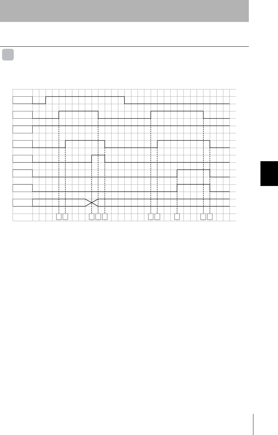
61
RFID System
User's Manual
Section 5 Timing Charts
Section 5
I/O Settings and Control Methods
Timing Charts
Trigger Mode
The Trigger Mode timing chart is shown below.
Mode Switch Settings 0 to 2 (4-byte, 26-byte, and 58-byte Access Modes)
ID Tag within the Antenna's Communications Range
ID Tag Not within Communications Range
A: The PLC turns ON TRG, and sends the execution command to DeviceNet Remote ID Controller.
B: The DeviceNet Remote ID Controller receives TRG, determines the CMD (command), LEN (data
length), and ADDR (start address), starts communications with ID Tag, and then turns ON BUSY.
C: The DeviceNet Remote ID Controller turns ON NORM when communications with ID Tag ends
normally.
D: Check from PLC that NORM Signal is ON, and then turn OFF TRG.
E: After confirming that TRG is OFF, the DeviceNet Remote ID Controller turns OFF BUSY and NORM.
F: The PLC turns ON TRG and sends execution command to DeviceNet Remote ID Controller.
G: The DeviceNet Remote ID Controller receives TRG, starts communications with ID Tag, and then
turns ON BUSY.
H: When communications with ID Tag ends in an error, DeviceNet Remote ID Controller turns ON ERR
(ID Tag communications error) and ERR_SUB0 (No ID Tag).
I: Confirm that the ERR signal is 1 (ON), and then turn OFF TRG.
J: After confirming that TRG is OFF, the DeviceNet Remote ID Controller turns OFF ERR and
ERR_SUB0.
Communications Range
ID Tag
TRG
RUN
BUSY
NORM
ERR1
ERR_SUB
ID
ABCDEFGH IJ
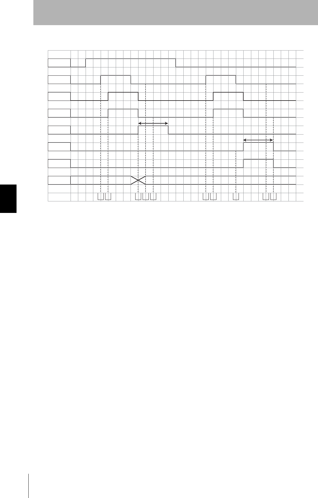
62
Section 5 Timing Charts
RFID System
User's Manual
Section 5
I/O Settings and Control Methods
Mode Switch Settings 3 and 4 (V600-compatible Trigger Mode)
ID Tag within the Antenna's Communications Range
ID Tag Not within Communications Range
A: The PLC turns ON TRG, and sends the execution command to DeviceNet Remote ID Controller.
B: The DeviceNet Remote ID Controller receives TRG, determines the CMD (command), LEN (data
length), and ADDR (start address), then turns ON HS output, starts communications with the ID Tag,
and turns ON BUSY.
C: HS output will turn OFF when TRG turns OFF.
D: The DeviceNet Remote ID Controller turns ON NORM when communications with ID Tag ends
normally.
E: The PLC checks that the NORM signal is ON, and then the data output is read.
F: Once the time set in the output mode has elapsed, the DeviceNet Remote ID Controller turns OFF
the data output and NORM.
G: The PLC turns ON TRG and sends execution command to DeviceNet Remote ID Controller.
H: The DeviceNet Remote ID Controller receives TRG, turns ON HS output, and then starts
communications with the ID Tag ID and turns ON BUSY.
I: HS output will turn OFF when TRG turns OFF.
J: When communications with ID Tag ends in an error, DeviceNet Remote ID Controller turns ON ERR
(ID Tag communications error) and ERR_SUB0 (No ID Tag).
K: The PLC confirms that the ERR signal is ON, and then the data output is read.
L: Once the time set in the output mode has elapsed, the DeviceNet Remote ID Controller turns OFF
ERR and ERR_SUB0.
Communications Range
ID Tag
TRG
RUN
BUSY
NORM
ERR1
ERR_SUB
ID
ABCDEFGH IJ
Set time
Set time
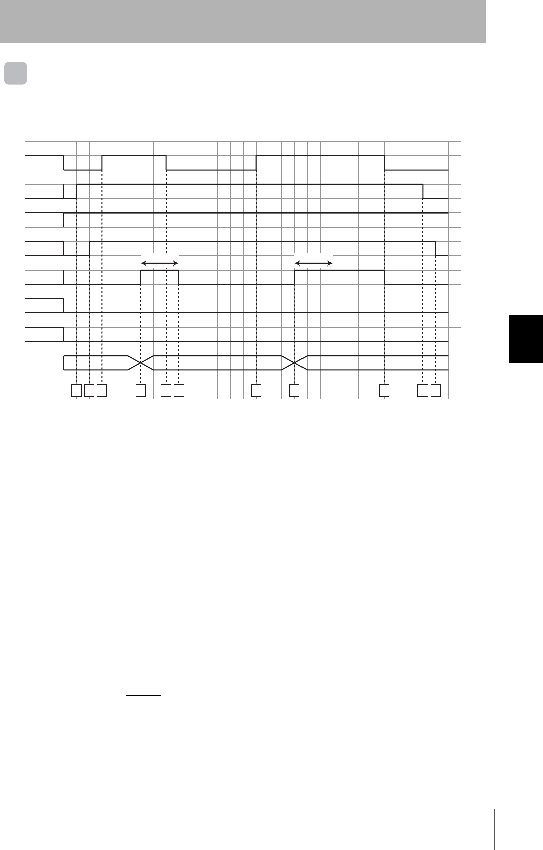
63
RFID System
User's Manual
Section 5 Timing Charts
Section 5
I/O Settings and Control Methods
Auto Mode with 100-ms Output Time
The timing chart for Auto Mode with a 100-ms output time is shown in the following figure.
Mode Switch Settings 0 to 2 (4-byte, 26-byte, and 58-byte Access Mode)
Communications
Range
ID Tag
INHIBIT
RUN
BUSY
NORM
ERR
ERR_SUB
ID
ABCDEFGHIJ
Communications Range
100 ms 100 ms
K
A: The PLC turns ON INHIBIT and sends the execution command to the DeviceNet Remote ID
Controller.
B: The DeviceNet Remote ID Controller checks that INHIBIT is ON, determines the CMD (command),
LEN (data length), and ADDR (start address), and then turns ON BUSY.
C: The DeviceNet Remote ID Controller starts communications with an ID Tag when one enters the
Antenna's communications range.
D: The DeviceNet Remote ID Controller turns ON NORM when communications with ID Tag end
normally.
E: The ID Tag moves outside the Antenna's communications range within 100 ms after the DeviceNet
Remote result is output.
F: The result output is turned OFF 100 ms after the DeviceNet Remote ID Controller result is output.
G: The DeviceNet Remote ID Controller starts communications with ID Tag when it enters the Antenna's
communications range.
H: The DeviceNet Remote ID Controller turns ON NORM when communications with the ID Tag ends
normally.
I: Result output is turned OFF when the ID Tag moves outside the Antenna's communications range
100 ms after the DeviceNet Remote ID Controller result is output.
J: The PLC turns OFF INHIBIT to prevent command execution by the DeviceNet Remote ID Controller.
K: The DeviceNet Remote ID Controller confirms that INHIBIT is OFF, and then turns OFF BUSY.

64
Section 5 Timing Charts
RFID System
User's Manual
Section 5
I/O Settings and Control Methods
Mode Switch Setting 5 (V600-compatible Auto Mode)
A: The PLC turns ON INHIBIT and sends the execution command to the DeviceNet Remote ID
Controller.
B: The DeviceNet Remote ID Controller checks that INHIBIT is ON, determines the CMD (command),
LEN (data length), and ADDR (start address), and then turns ON BUSY.
C: The DeviceNet Remote ID Controller starts communications with an ID Tag when one enters the
Antenna's communications range.
D: The DeviceNet Remote ID Controller turns ON NORM when communications with ID Tag end
normally.
E: The ID Tag moves outside the Antenna's communications range within 100 ms after the DeviceNet
Remote result is output.
F: The result output is turned OFF 100 ms after the DeviceNet Remote ID Controller result is output.
G: The DeviceNet Remote ID Controller starts communications with ID Tag when it enters the Antenna's
communications range.
H: The DeviceNet Remote ID Controller turns ON NORM when communications with the ID Tag ends
normally.
I: The PLC turns OFF INHIBIT when processing continues with the ID Tag in the Antenna's
communications range.
J: The DeviceNet Remote ID Controller confirms that INHIBIT is OFF, and then turns ON HS output and
turns OFF the result output.
K: The PLC turns ON INHIBIT, detects an ID Tag again, and starts communications.
Communications
Range
ID Tag
INHIBIT
RUN
BUSY
NORM
ERR
ERR_SUB
ID
Communications Range
100 ms
ABCDEFGHIJK
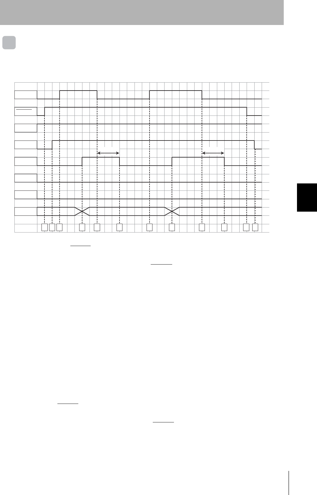
65
RFID System
User's Manual
Section 5 Timing Charts
Section 5
I/O Settings and Control Methods
Auto Mode (500 ms Output Time)
The timing chart for Auto Mode with a 500-ms output time is shown in the following figure.
Mode Switch Settings 0 to 2 (4-byte, 26-byte, and 58-byte Access Mode)
A: The PLC turns ON INHIBIT, and sends the execution command to the DeviceNet Remote ID
Controller.
B: The DeviceNet Remote ID Controller checks that INHIBIT is ON, determines the CMD (command),
LEN (data length), and ADDR (start address), and then turns ON BUSY.
C: The DeviceNet Remote ID Controller starts communications with an ID Tag when one enters the
Antenna's communications range.
D: The DeviceNet Remote ID Controller turns ON NORM when communications with the ID Tag ends
normally.
E: The ID Tag moves out of the Antenna's communications range.
F: The DeviceNet Remote ID Controller waits for the ID Tag to leave the Antenna's communications
range, and then turns OFF the result output 500 ms afterward.
G: The DeviceNet Remote ID Controller starts communications with the ID Tag when one enters the
Antenna's communications range.
H: The DeviceNet Remote ID Controller turns ON NORM when communications with the ID Tag ends
normally.
I: The DeviceNet Remote ID Controller waits for the ID Tag to move outside the Antenna's
communications range, and then turns ON the result output 500 ms afterward.
J: The PLC sets INHIBIT to 0 (OFF) to prevent command execution by the DeviceNet Remote ID
Controller.
K: The DeviceNet Remote ID Controller confirms that INHIBIT is OFF, and then turns OFF BUSY.
Communications
Range
ID Tag
INHIBIT
RUN
BUSY
NORM
ERR
ERR_SUB
ID
Communications
Range
500 ms 500 ms
ABCDEFGHIJKL

66
Section 5 Timing Charts
RFID System
User's Manual
Section 5
I/O Settings and Control Methods
Mode Switch Setting 6 (V600-compatible Auto Mode)
A: The PLC turns ON INHIBIT, and sends the execution command to the DeviceNet Remote ID
Controller.
B: The DeviceNet Remote ID Controller checks that INHIBIT is ON, determines the CMD (command),
LEN (data length), and ADDR (start address), and then turns ON BUSY.
C: The DeviceNet Remote ID Controller starts communications with an ID Tag when one enters the
Antenna's communications range.
D: The DeviceNet Remote ID Controller turns ON NORM when communications with the ID Tag is
finished.
E: The ID Tag moves outside the Antenna's communications range within 500 ms after the DeviceNet
Remote result is output.
F: The result output is turned OFF 500 ms after the DeviceNet Remote ID Controller result is output.
G: The DeviceNet Remote ID Controller starts communications with the ID Tag when one enters the
Antenna's communications range.
H: The DeviceNet Remote ID Controller turns ON NORM when communications with the ID Tag is
finished.
I: The PLC turns OFF INHIBIT when processing continues with the ID Tag in the Antenna's
communications range.
J: The DeviceNet Remote ID Controller confirms that INHIBIT is OFF, and then turns ON HS output and
turns OFF the result output.
K: The PLC turns ON INHIBIT, detects the ID Tag again, and starts communications.
ID Tag
INHIBIT
RUN
BUSY
NORM
ERR
ERR_SUB
ID
Communications
Range
Communications Range
500 ms
ABCDEFGHIJK
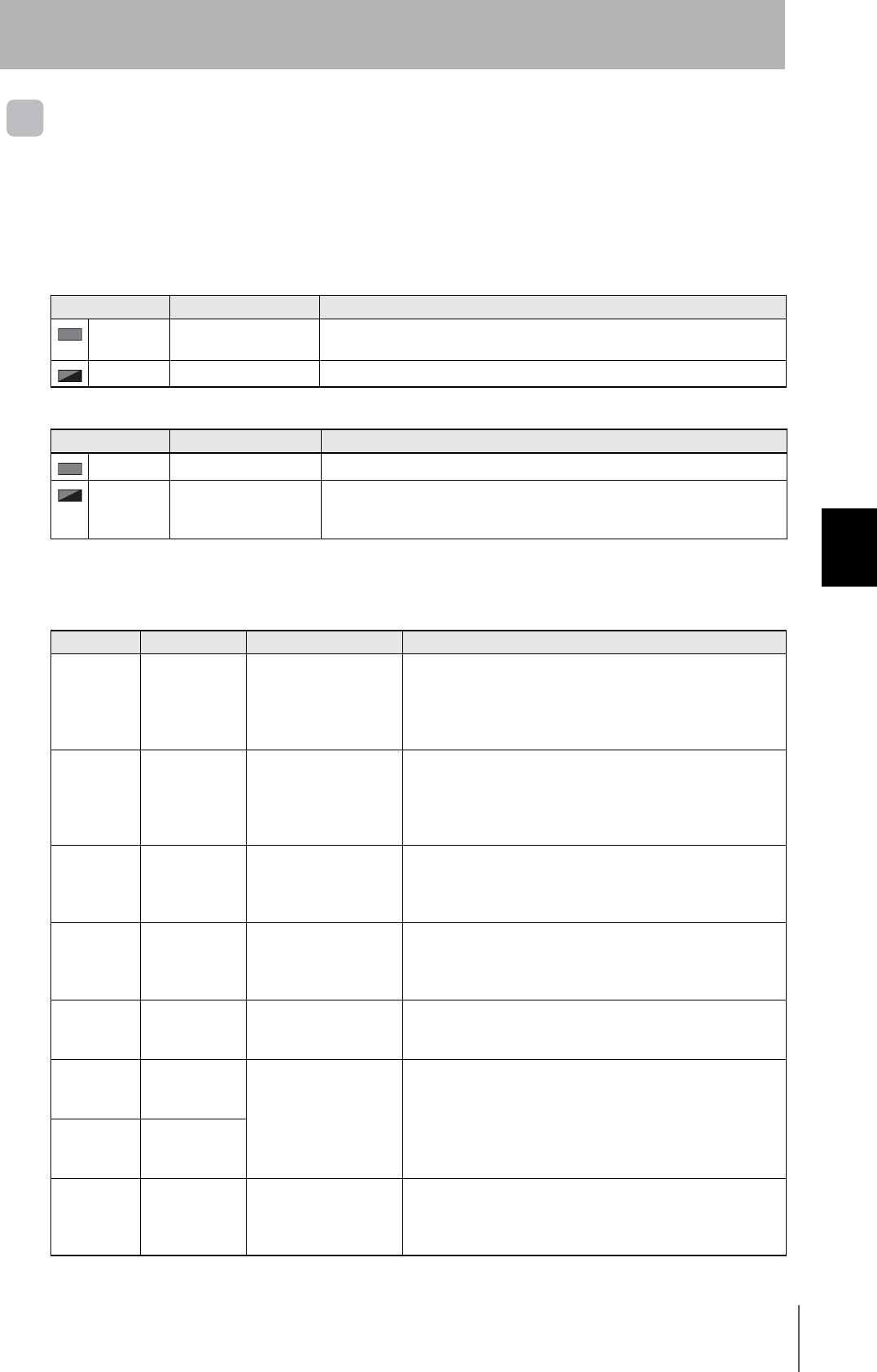
67
RFID System
User's Manual
Section 5 Timing Charts
Section 5
I/O Settings and Control Methods
Noise Check Control
Handling Errors
Check the status of the DeviceNet Remote ID Controller network and hardware by using the MS and
NS operation indicators.
MS Indicator (Machine Status)
NS Indicator (Network Status)
RFID-related Errors
When the ERR indicator lights, check the LED indicators from bit 7 to bit 0 or the error output for errors
relating to RFID, and then take suitable actions
Error Corrective action
Lit red Hardware error If the error continues after resetting the power, replace the DeviceNet Remote ID
Controller.
Flashing red Settings error Set the node address switches within the correct range.
Error Corrective action
Lit red Duplicate node address Assign unique node addresses to all nodes within the same network.
Flashing red Leaving link Check whether the communications cable is connected correctly. If noise enters
on the communications cable, the node made leave the link. Take suitable noise
countermeasures.
Indicator Output bits Error Corrective action
Bit 0
Flashing red
Error
Termination + ID
Tag Missing
Error
An ID Tag could not be
detected in Trigger Mode.
Change the control timing so that communications can be started
while the ID Tag is within the Antenna's communications range.
Measure the noise and take suitable noise countermeasures.
Check the effect of surrounding metal and make sure that the
desired communications distance can be obtained.
Bit 1
Flashing red
Error
Termination + ID
Tag Missing
Error
ID Tag was detected in
Trigger Mode but
communications could
not be ended normally.
Change the control timing so that communications can be started
while the ID Tag is within the Antenna's communications range.
Measure the noise and take suitable noise countermeasures.
Check the effect of surrounding metal and make sure that the
desired communications distance can be obtained.
Bit 2
Flashing red
Error
Termination +
Address Error
The command specified
a memory area outside
the ID Tag memory
range.
Set the command memory area within the ID Tag memory range.
Bit 3
Flashing red
Error
Termination +
Protection Error
The command specified
data to be written to the
write-protected area of ID
Tag.
Set the command memory area to outside the write-protected
area.
Bit 4
Flashing red
Error
Termination +
Mismatch Error
Data was not correctly
written to ID Tag.
Retry the writing process.
If the error persists, replace the ID Tag.
Bit 5
Flashing red
Error
Termination + ID
System Error 1
ID Tag used is not
supported by the
DeviceNet Remote ID
Controller.
Change the ID Tag to one supported by the DeviceNet Remote
ID Controller.
Bit 6
Flashing red
Error
Termination + ID
System Error 2
Bit 0 and bit 4
Flashing red
Error
Termination +
Command Error
There is an error with the
execution command, or
the command cannot not
be received.
Check the command, address, and number of bytes to process.

68
Section 5 Timing Charts
RFID System
User's Manual
Section 5
I/O Settings and Control Methods
Bit 7 to bit 0
Flashing red
Error
Termination +
Switch Error
Mode switch setting error Set the mode switch correctly.
Bit 7 to bit 0
Lit red
Error
Termination +
System Error
The DeviceNet Remote
ID Controller cannot
operate.
If the error continues after resetting the power, replace the
DeviceNet Remote ID Controller.
Indicator Output bits Error Corrective action

Section 6 Appendices
69
RFID System
User's Manual
Section 6
Appendices
Product Specifications 70
Dimensions 78
Characteristics 87
Reference Data 102
Chemical Resistance of the Antennas 128
Chemical Resistance of Tags 129
Degree of Protection 136
70
Section 6 Product Specifications
RFID System
User's Manual
Section 6
Appendices
Product Specifications
DeviceNet Remote ID Controller
General Specifications
V680-HAM42-DRT
Item Model V680-HAM91/V680-HAM81
Supply volTage 24 VDC +10%/-15%, Ripple (p-p): 10% max.
Power consumption 3.6 W (5 W max.)
Ambient operating
temperature
−10 to 55°C (with no icing)
Ambient storage
temperature
−20 to 65°C (with no icing)
Ambient operating
humidity
25% to 85% (with no condensation)
Insulation resistance 20 MΩ min. (at 500 VDC) between cable terminals and case
Dielectric strength 1000 VAC (50/60 Hz) for 1 minute between cable terminals and case
Vibration resistance 10 to 150 Hz, 0.2-mm double amplitude at 15 m/s2 in X, Y, and Z directions ten sweeps each for
8 minutes
Shock resistance 150 m/s2 in X, Y, and Z directions 3 times each (18 times in total)
Dimensions 90 × 30 × 65 mm (excluding protruding parts)
Degree of protection Panel-mounting (conforms to IP20)
Material PC+ABS
Weight Approx. 130 g
Mounting method DIN Track
RFID System
User's Manual
71
Section 6 Product Specifications
Section 6
Appendices
Antenna
Four models of Antennas can be used with I/O Sensors. Select the best Antenna for the application.
General Specifications
V680-HS51
Item Model V680-HS51
Ambient operating
temperature
−10 to 60°C (with no icing)
Ambient storage
temperature
−25 to 75°C (with no icing)
Ambient operating
humidity
35% to 95% (with no condensation)
Insulation resistance 20 MΩ min. (at 500 VDC) between cable terminals and case
Dielectric strength 1,000 VAC, 50/60Hz for 1 min between cable terminals and case
Degree of protection IP67 (IEC60529)
In-house standard for Antenna oil resistance (former JEM standard equivalent to IP67g) (Read/
Write Antenna portion)
Note: The Connector is not waterproof.
Vibration resistance 10 to 2,000 Hz variable vibration, 1.5-mm double amplitude at 150 m/s2 acceleration, with 10
sweeps in X, Y, and Z directions for 15 minutes each
Shock resistance 1,000 m/s2 in X, Y, and Z directions 3 times each (18 times in total)
Dimensions M12 × 35 mm
Material ABS, brass, epoxy resin filling
Weight Approx. 55 g
Cable length Standard length of 2 m
V680-HS52-W/-R
Item Model V680-HS52-W
(Standard cable, waterproof connector)
V680-HS52-R
(Flexible cable, non-waterproof connector)
Ambient operating
temperature
−10 to 60°C (with no icing)
Ambient storage
temperature
−25 to 75°C (with no icing)
Ambient operating
humidity
35% to 95% (with no condensation)
Insulation resistance 20 MΩ min. (at 500 VDC) between cable terminals and the case
Dielectric strength 1,000 VAC, 50/60 Hz for 1 min between cable terminals and case
Degree of protection IP67 (IEC60529)
In-house standard for Antenna oil resistance
(former JEM standard equivalent to IP67g)
Note: The connector specifications are IP67 and
IP65 (IEC60529).
IP67 (IEC60529)
In-house standard for Antenna oil resistance
(former JEM standard equivalent to IP67g)
Note: The connectors are not waterproof.
Vibration resistance 10 to 500 Hz, 1.5-mm double amplitude, acceleration: 100 m/s2, 1 sweep in each of 3 axis directions
(up/down, left/right, and forward/backward) for 8 minutes each
Shock resistance 500 m/s2, 3 times each in 6 directions (Total: 18 times)
Dimensions M22 × 65 mm
Material ABS resin, brass, and epoxy resin filler
Weight Approx. 850 g (with 12.5 m cable)
Cable length Standard lengths of 2 and 12.5 m
72
Section 6 Product Specifications
RFID System
User's Manual
Section 6
Appendices
V680-HS63-W/-R
Item Model V680-HS63-W
(Standard cable, waterproof connector)
V680-HS63-R
(Flexible cable, non-waterproof connector)
Ambient operating
temperature
−10 to 60°C (with no icing)
Ambient storage
temperature
−25 to 75°C (with no icing)
Ambient operating
humidity
35% to 95% (with no condensation)
Insulation resistance 20 MΩ min. (at 500 VDC) between cable terminals and case
Dielectric strength 1,000 VAC, 50/60 Hz for 1 min between cable terminals and case
Degree of protection IP67 (IEC60529)
In-house standard for Antenna oil resistance
(former JEM standard equivalent to IP67g)
Note: The connector specifications are IP67 and
IP65 (IEC 60529).
IP67 (IEC60529)
In-house standard for Antenna oil resistance
(former JEM standard equivalent to IP67g)
Note: The connectors are not waterproof.
Vibration resistance 10 to 500 Hz, 1.5-mm double amplitude, acceleration: 100 m/s2, 10 sweeps in each of 3 axis directions
up/down, left/right, and forward/backward) for 11 minutes each
Shock resistance 500 m/s2, 3 times each in 6 directions (Total: 18 times)
Dimensions 40 × 53 × 23 mm
Material ABS resin case, epoxy resin filler
Weight Approx. 850 g (with 12.5 m cable)
Cable length Standard lengths of 2 and 12.5 m
V680-HS65-W/-R
Item Model V680-HS65-W
(Standard cable, waterproof connector)
V680-HS65-R
(Flexible cable, non-waterproof connector)
Ambient operating
temperature
−25 to 70°C (with no icing)
Ambient storage
temperature
−40 to 85°C (with no icing)
Ambient operating
humidity
35% to 95% (with no condensation)
Insulation resistance 20 MΩ min. (at 500 VDC) between cable terminals and case
Dielectric strength 1,000 VAC, 50/60 Hz for 1 min between connector terminals and case
Degree of protection IP67 (IEC60529)
In-house standard for Antenna oil resistance
(former JEM standard equivalent to IP67g)
Note: The connector specifications are IP67 and
IP65 (IEC 60529).
IP67 (IEC60529)
In-house standard for Antenna oil resistance
former JEM standard equivalent to IP67g)
Note: The connectors are not waterproof.
Vibration resistance 10 to 500 Hz, 1.5-mm double amplitude, acceleration: 100 m/s2, 10 sweeps in each of 3 axis directions
up/down, left/right, and forward/backward) for 11 minutes each
Shock resistance 500 m/s2, 3 times each in 6 directions (Total: 18 times)
Dimensions 100 × 100 × 30 mm
Material ABS resin case, epoxy resin filler
Weight Approx. 1,100 g (with 12.5 m cable)
Cable length Standard lengths of 2 and 12.5 m

RFID System
User's Manual
73
Section 6 Product Specifications
Section 6
Appendices
ID Tags
General Specifications
V680-D1KP52MT
Item Model V680-D1KP52MT
Memory capacity 1,000 bytes (user area)
Memory type EEPROM
Data backup time 10 years after writing (85°C or less), 0.5 years after writing (125°C max.)
Memory longevity 100,000 times per block (25°C)
Ambient operating
temperature when
communicating
−25 to 85°C (with no icing)
Ambient operating
temperature when not
communicating
−40 to 125°C (with no icing)
Ambient storage
temperature
−40 to 125°C (with no icing)
Ambient operating
humidity
35% to 95%
Degree of protection IP68 (IEC 60529) (See note.)
In-house standard for Antenna oil resistance (former JEM standard equivalent to IP67g)
Vibration resistance 10 to 2,000 Hz, 1.5-mm double amplitude, acceleration: 150 m/s2, 10 sweeps each in X, Y, and Z
directions for 15 minutes each
Shock resistance 500 m/s2, 3 times each in X, Y, and Z directions (Total: 18 times)
Dimensions 8 dia. × 5 mm
Materials Case: PPS resin, Fill resin: Epoxy resin
Weight Approx. 0.5 g
Metal countermeasures Yes
Note: OMRON Test Method
Usage condition: 10 m or less under water in natural conditions
1. No water ingress after 1 hour under water at 2 atmospheres of pressure.
2. Sensing distance and insulation resistance specifications must be met after 100 repetitions of half hour in 5°C water
and half hour in 85°C water.

74
Section 6 Product Specifications
RFID System
User's Manual
Section 6
Appendices
The V680-D1KP66MT is designed to be mounted directly to metal. The V680-D1KP66T and V680-
D1KP66MT markings are shown in the following diagrams.
The side with the markings is the communications surface. Mount the Tag with this side facing the Antenna.
The ID READ command is used to write the ID code to the ID Tag's memory, and therefore will be affected by the
ambient temperature. Be careful when using the ID Tag in environments with high ambient temperatures.
V680-D1KP66T/-D1KP66MT
Item Model V680-D1KP66T V680-D1KP66MT
Memory capacity 1,000 bytes (user area)
Memory type EEPROM
Data backup time 10 years after writing (85°C or less), 2.5 years after writing (125°C max.)
Memory longevity 100,000 times per block (25°C)
Ambient operating
temperature when
communicating
−25 to 85°C (with no icing)
Ambient operating
temperature when not
communicating
−40 to 125°C (with no icing)
Ambient storage
temperature
−40 to 125°C (with no icing)
Ambient operating
humidity
35% to 95%
Degree of protection IP68 (IEC 60529) (See note.)
In-house standard for Antenna oil resistance (former JEM standard equivalent to IP67g)
Vibration resistance 10 to 2,000 Hz, 1.5-mm double amplitude, acceleration: 150 m/s2, 10 sweeps each in X, Y, and Z
directions for 15 minutes each
Shock resistance 500 m/s2, 3 times each in X, Y, and Z directions (Total: 18 times)
Dimensions 34 × 34 × 3.5 mm
Materials Case: PPS resin
Weight Approx. 6 g Approx. 7.5 g
Metal countermeasures None Yes
Note: OMRON Test Method
Usage condition: 10 m or less under water in natural conditions
1. No water ingress after 1 hour under water at 2 atmospheres of pressure.
2. Sensing distance and insulation resistance specifications must be met after 100 repetitions of half hour in 5°C water
and half hour in 85°C water.
z V680-D1KP66MT z V680-D1KP66T

RFID System
User's Manual
75
Section 6 Product Specifications
Section 6
Appendices
V680-D1KP66T-SP
Item Specifications
Memory capacity 1,000 bytes
Memory type EEPROM
Data backup time 10 years after writing (85°C or less)
Memory longevity 100,000 times per block (25°C)
Ambient operating
temperature
When communicating: −25 to 70°C (with no icing)
When not communicating: −40 to 110°C (with no icing)
Ambient operating
humidity
35% to 95% (with no condensation)
Ambient storage
temperature
−40 to 110°C (with no icing)
Ambient storage humidity 35% to 95% (with no condensation)
Vibration resistance 10 to 2,000 Hz, 1.5-mm double amplitude at 150 m/s2 in X, Y, and Z directions 10 sweeps each for
15 minutes
Shock resistance 5500 m/s2, 3 times each in 6 directions (Total: 18 times)
Dimensions 95 × 36.5 × 6.5 mm (excluding protruding parts)
Degree of protection IP67
Material External coating: Fluororesin (PFA)
Tag body: PPS resin
Weight Approx. 20 g
Mounting method Two M5 screws
Metal countermeasures None
V680-D2KF52M
Item Model V680-D2KF52M
Memory capacity 2,000 bytes (user area)
Memory type FRAM
Data backup time 10 years after writing (55°C or less), 2.9 years after writing (85°C max.)
Memory longevity 10 billion times per block. Access frequency (See note): 10 billion times
Ambient operating
temperature
−25 to 85°C (with no icing)
Ambient storage
temperature
−40 to 85°C (with no icing)
Ambient operating
humidity
35% to 85%
Degree of protection IP67 (IEC 60529)
In-house standard for oil resistance (former JEM standard equivalent to IP67g)
Vibration resistance 10 to 2,000 Hz, 1.5-mm double amplitude, acceleration: 150 m/s2, 10 sweeps each in X, Y, and Z
directions for 15 minutes each
Shock resistance 500 m/s2, 3 times each in X, Y, and Z directions (Total: 18 times)
Dimensions 8 dia. × 5 mm
Materials Case: PPS resin, Fill resin: Epoxy resin
Weight Approx. 0.5 g
Metal countermeasures Yes
Note: The total communications frequency of the Read or Write is called an access frequency.
76
Section 6 Product Specifications
RFID System
User's Manual
Section 6
Appendices
The V680-D2KF67M is designed to be mounted directly to metal. The V680-D2KF67 and V680-
D2KF67M markings are shown in the following diagrams.
The side with the markings is the communications surface. Mount the Tag with this side facing the Antenna.
The ID READ command is used to write the ID code to the ID Tag's memory, and therefore will be affected by the
ambient temperature. Be careful when using the ID Tag in environments with high ambient temperatures.
V680-D2KF67/-D2KF67M
Item Model V680-D2KF67 V680-D2KF67M
Memory capacity 2,000 bytes (user area)
Memory type FRAM
Data backup time 10 years after writing (55°C or less), 2.9 years after writing (85°C max.)
Memory longevity 10 billion times per block. Access frequency (See note.): 10 billion times
Ambient operating
temperature
−25 to 85°C (with no icing)
Ambient storage
temperature
−40 to 85°C (with no icing)
Ambient operating
humidity
35% to 85%
Degree of protection P67 (IEC 60529)
In-house standard for oil resistance (former JEM standard equivalent to IP67g)
Vibration resistance 10 to 2,000 Hz, 1.5-mm double amplitude, acceleration: 150 m/s2,10 sweeps each in X, Y, and Z
directions for 15 minutes each
Shock resistance 500 m/s2, 3 times each in X, Y, and Z directions (Total: 18 times)
Dimensions 40 × 40 × 4.5 mm
Materials Case: ABS resin
Weight Approx. 6.5 g Approx. 7 g
Metal countermeasures None Yes
Note: The total communications frequency of the Read or Write is called an access frequency.
z V680-D2KF67M z V680-D2KF67

RFID System
User's Manual
77
Section 6 Product Specifications
Section 6
Appendices
V680-D8KF68/-D32KF68
Item Model V680-D8KF68 V680-D32KF68
Memory capacity 8,192 bytes (user area) 32,744 bytes (user area)
Memory type FRAM
Data backup time 10 years after writing (70°C max.), 6 years after writing (85°C max.)
Memory longevity 10 billion times per block (85°C or less)
Access frequency (See note.): 10 billion times
Ambient operating
temperature
−20 to 85°C (with no icing)
Ambient storage
temperature
−40 to 85°C (with no icing)
Ambient operating
humidity
35% to 85%
Degree of protection P67 (IEC 60529)
In-house standard for oil resistance (former JEM standard equivalent to IP67g)
Vibration resistance 10 to 500 Hz, 1.5-mm double amplitude, acceleration: 100 m/s2, 10 sweeps each in X, Y, and Z
directions for 11 minutes each
Shock resistance 500 m/s2, 3 times each in X, Y, and Z directions (Total: 18 times)
Dimensions 86 × 54 × 10 mm
Materials Case: PBT resin
Fill resin: Epoxy resin
Weight Approx. 50 g
Metal countermeasures None
Note: The total communications frequency of the Read or Write is called an access frequency.
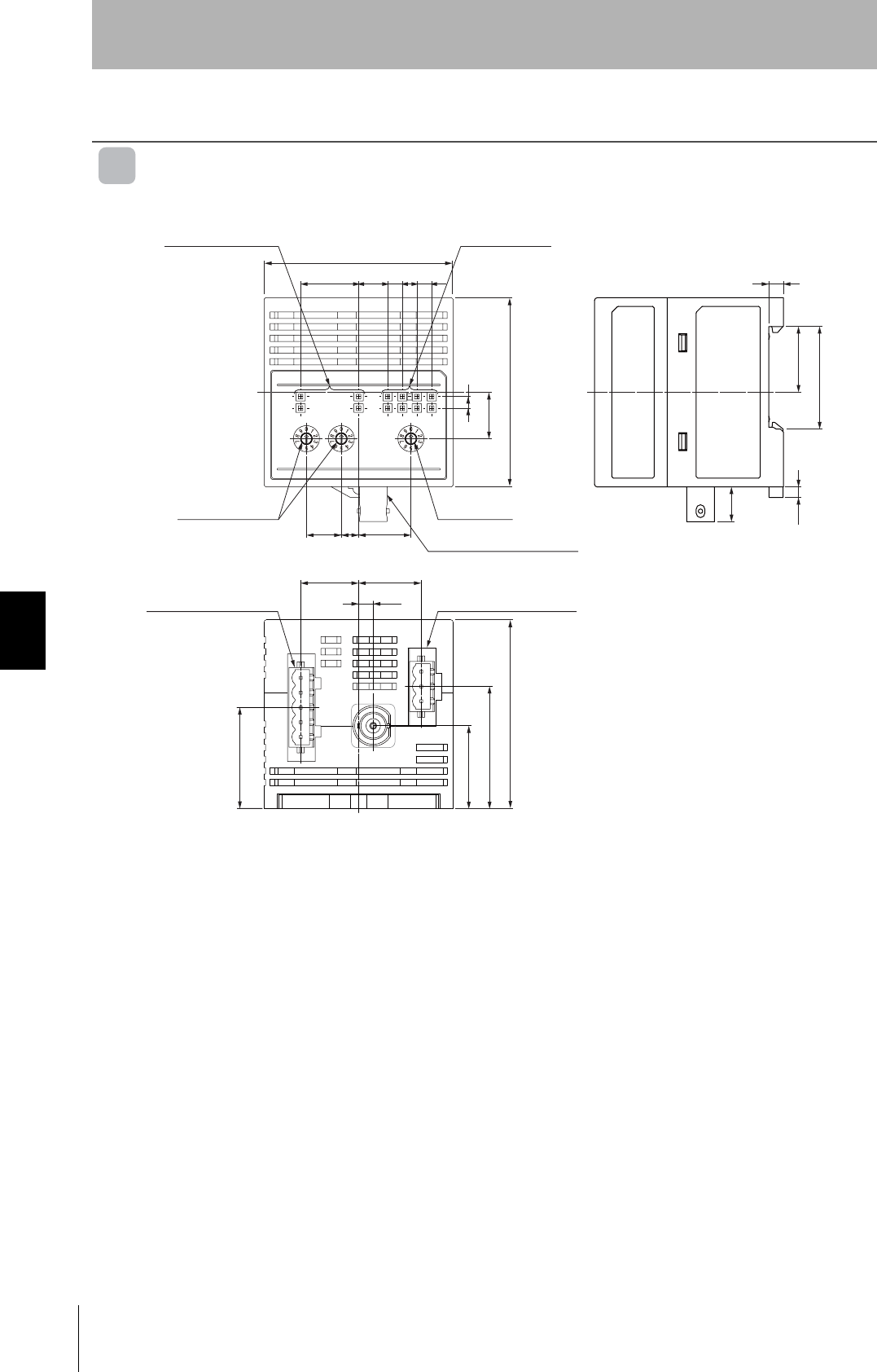
78
Section 6 Dimensions
RFID System
User's Manual
Section 6
Appendices
Dimensions
DeviceNet Remote ID Controller
V680-HAM42-DRT
Operation indicator Data indicator
Node address
switches Mode switch
Antenna connector port
65
20 10 55
12 18
6
5
35.2
22.6
12
(3.7)
65
41.8
25.8
35
20.5 21.5
5.06 Power supply terminals
DeviceNet connector
(Unit: mm)
RFID System
User's Manual
79
Section 6 Dimensions
Section 6
Appendices
Antennas
V680-HS51
Case material Brass
Communications surface ABS resin
Fill resin Epoxy resin
Cable PVC (gray)
(16.8 dia.)
(Unit: mm)
(14.5 dia.)
12
9.6 dia.
Connector
Ferrite core
50
25
Two toothed washers
Two lock nuts
Coaxial cable, 2.9 dia.,
standard length: 2 m
15
35
33
24
7
M12 x 1
21 dia.
12.5 dia.
17
Mounting Hole Dimensions
Insulation cover
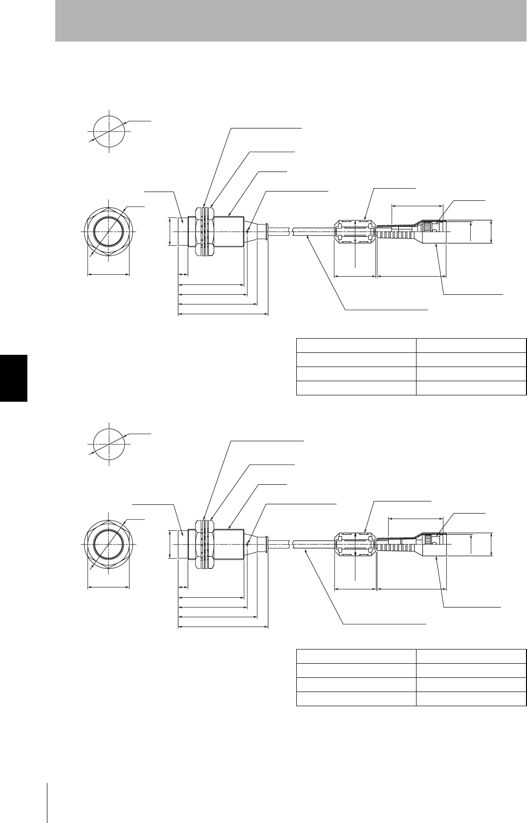
80
Section 6 Dimensions
RFID System
User's Manual
Section 6
Appendices
V680-HS52
V680-HS52-W
V680-HS52-R
Case material Brass
Communications surface ABS resin
Fill resin Epoxy resin
Cable PVC (gray)
Case material Brass
Communications surface ABS resin
Fill resin Epoxy resin
Cable PVC (black)
16.8 dia.
(Unit: mm)
14.5 dia.
Connector
Ferrite core
Insulation cover
37
50
30
16.5 dia.
Two toothed washers
Two lock nuts
M22 × 1
Operation indicator
Coaxial cable, 5.5 dia.,
standard length: 2 m
65
57
50
47.8
7
35 dia.
Antenna
22.5 dia.
Mounting Hole Dimensions
30
19.8 dia.
16.8 dia.
(Unit: mm)
14.5 dia.
Connector
Ferrite core
Insulation cover
(39.5)
50
30
16.5 dia.
Two toothed washers
Two lock nuts
M22 × 1
Operation indicator
Coaxial cable, 5.3 dia.,
standard length: 2 m
47.6
7
35 dia.
Antenna
22.5 dia.
Mounting Hole Dimensions
30
50
57
65

RFID System
User's Manual
81
Section 6 Dimensions
Section 6
Appendices
V680-HS63-R/-W
V680-HS63-W
V680-HS63-R
Case material ABS resin
Fill resin Epoxy resin
Cable PVC (gray)
Case material ABS resin
Fill resin Epoxy resin
Cable PVC (black)
(Unit: mm)
Connector
Ferrite core
Insulation cover
37
50
30
16.5 dia.
Coaxial cable, 5.5 dia.,
standard length: 2 m
Operation indicator
16.8 dia.
14.5 dia.
Two, M4 or 4.5 dia. holes
Antenna
53
27 6
5
Coil center
Note: Mounting Hole Dimensions
40
5
28±0.1
16.8 dia.
(Unit: mm)
14.5 dia.
Connector
Ferrite core
Insulation cover
37
50
30
16.5 dia.
Coaxial cable, 5.3 dia.,
standard length: 2 m
Operation indicator
Antenna
Note: Mounting Hole Dimensions
Coil center
Two, M4 or 4.5 dia. holes
40
28±0.1
53
27 6
5
5
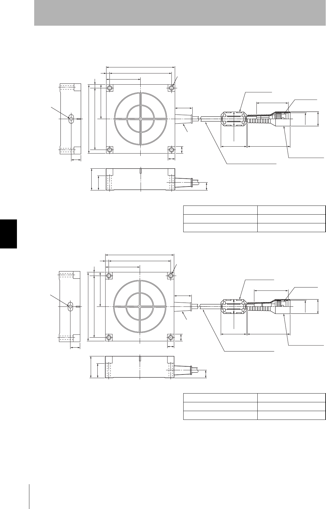
82
Section 6 Dimensions
RFID System
User's Manual
Section 6
Appendices
V680-HS65-R/-W
V680-HS65-W
V680-HS65-R
Case material ABS resin
Fill resin Epoxy resin
Cable PVC (gray)
Case material ABS resin
Fill resin Epoxy resin
Cable PVC (black)
16.8 dia.
(Unit: mm)
14.5 dia.
Connector
Ferrite core
Insulation cover
37
50
30
16.5 dia.
Coaxial cable, 5.5 dia.,
standard length: 2 m
Operation
indicator
100
90±0.2
90±0.2
100
50
5
5
30
20
10
10
50
Bushing
Four, 4.5 dia.
(Mounting holes)
11
16.8 dia.
(Unit: mm)
14.5 dia.
Connector
Ferrite core
Insulation cover
37
50
16.5 dia.
Coaxial cable, 5.3 dia.,
standard length: 2 m
Bushing
Four, 4.5 dia.
(Mounting holes)
Operation
indicator
100
90±0.2
90±0.2
100
50
5
5
30
20
10
10
50
11
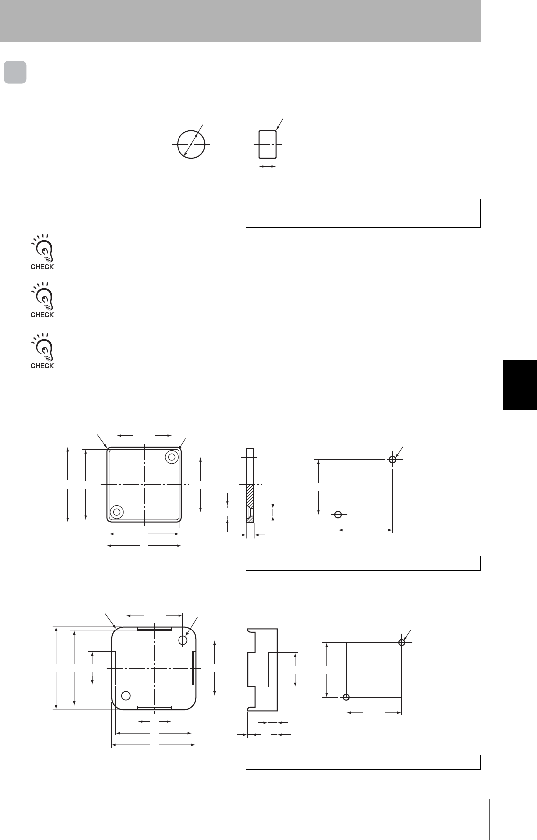
RFID System
User's Manual
83
Section 6 Dimensions
Section 6
Appendices
ID Tags
V680-D1KP52MT
When embedding the V680-D1KP52MT into a metal surface, use the V680-HS52 Antenna.
Transmission will not be possible if the V680-HS63 Antenna is used.
The side with the markings is the communications surface. Mount the Tag with this side facing the Antenna.
The ID READ command is used to write the ID code to the ID Tag's memory, and therefore will be affected by the
ambient temperature. Be careful when using the ID Tag in environments with high ambient temperatures.
V680-D1KP66T/-D1KP66MT
V600-A86 Attachment
Case material ABS resin
Fill resin Epoxy resin
Case material PPS resin
Case material PPS resin
R0.2
8dia.
0
−0.1
5
0
−0.1
(Unit: mm)
(Unit: mm)
25±0.2 Four, R8
Four, R4
34 32
32
34
25±0.2
35±0.1
Two, M3
25±0.2
25±0.2
Two, 3.5 dia.
Two, 6 dia.
(Unit: mm)
25±0.2 Two, 4 dia.
Four, R5.5
34
37
37
34
25±0.2
Two, M3
25±0.2
25±0.2
15
15
10
16
3.5
4
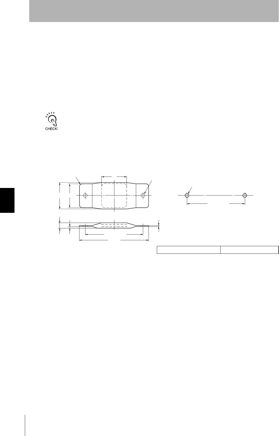
84
Section 6 Dimensions
RFID System
User's Manual
Section 6
Appendices
Tag Heat Resistivity
•Storing Tags under high temperatures will adversely affect the performance of the internal parts and
the service life of the Tags.
•An LTPD of 10% was determined during the evaluation for Tags that reached the end of their life after
testing under the following test conditions.
LTPD: Lot tolerance percent defective
The lower limit of the malfunction rate for lots to be considered unacceptable during reliability testing.
V680-D1KP66T-SP
Heat cycle −10°C/+150°C, 30 minutes each for 1,000 cycles
−10°C/+180°C, 30 minutes each for 200 cycles
High temperatures +150°C 1,000 hours
+180°C, 2,000 hours
Case material PFA resin
Mounting Hole Dimensions
(Unit: mm)
80±0.2
Four, R6 34
36.5 34
Two, M5
80±0.2
95
1.3
6.5 2.5
max.
Two, 5.5 dia.
(Mounting hole)
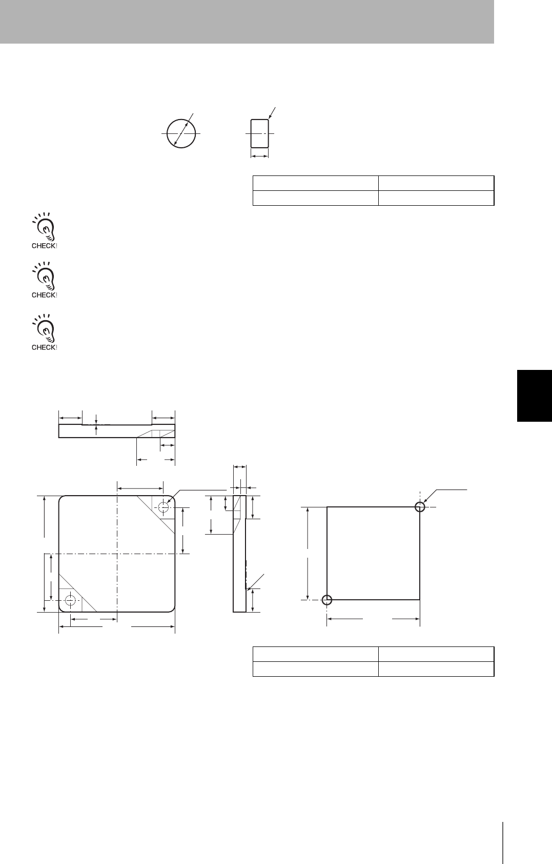
RFID System
User's Manual
85
Section 6 Dimensions
Section 6
Appendices
V680-D2KF52M
When embedding the V680-D1KP52M into a metal surface, use the V680-HS51/-HS52 Antenna.
Transmission will not be possible if the V680-HS63 Antenna is used.
The side with the markings is the communications surface. Mount the Tag with this side facing the Antenna.
The ID READ command is used to write the ID code to the ID Tag's memory, and therefore will be affected by the
ambient temperature. Be careful when using the ID Tag in environments with high ambient temperatures.
V680-D2KF67/-D2KF67M
Case material PPS resin
Fill resin Epoxy resin
Case material ABS resin
Fill resin Epoxy resin
(Unit: mm)
8dia.
0
−0.1
R0.2
5
0
−0.1
Mounting Hole Dimensions
(Unit: mm)
32±0.2
32±0.2
Two, M3
4.5
2
5.2
13.2
8
Mounting
reference
surface
16
Two, 3.5-dia.
mounting holes
16
13.2
5.2
8
80.2
40±0.1
−0.5
16
16
40±0.1
−0.5
8
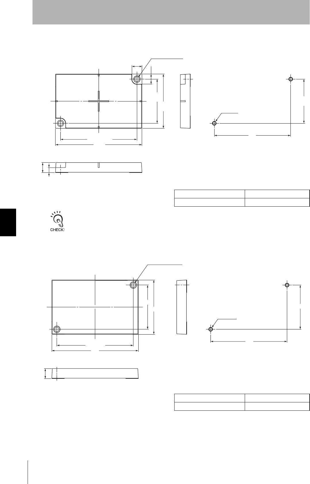
86
Section 6 Dimensions
RFID System
User's Manual
Section 6
Appendices
V680-D8KF68/-D32KF68
The side with the markings is the communications surface. Mount the Tag with this side facing the Antenna.
V680-A81 Attachment
Case material PBT resin
Fill resin Epoxy resin
Case material PBT resin
Fill resin Epoxy resin
Mounting Hole Dimensions
(Unit: mm)
Two, M4
44
54
44±0.2
44±0.2
54
10
Two, 4.5-dia.
mounting holes
10
10
5
76
Mounting Hole Dimensions
(Unit: mm)
Two, M4
Two, 4.5-dia.
mounting holes
44
76
54
44±0.2
86
76±0.2
10
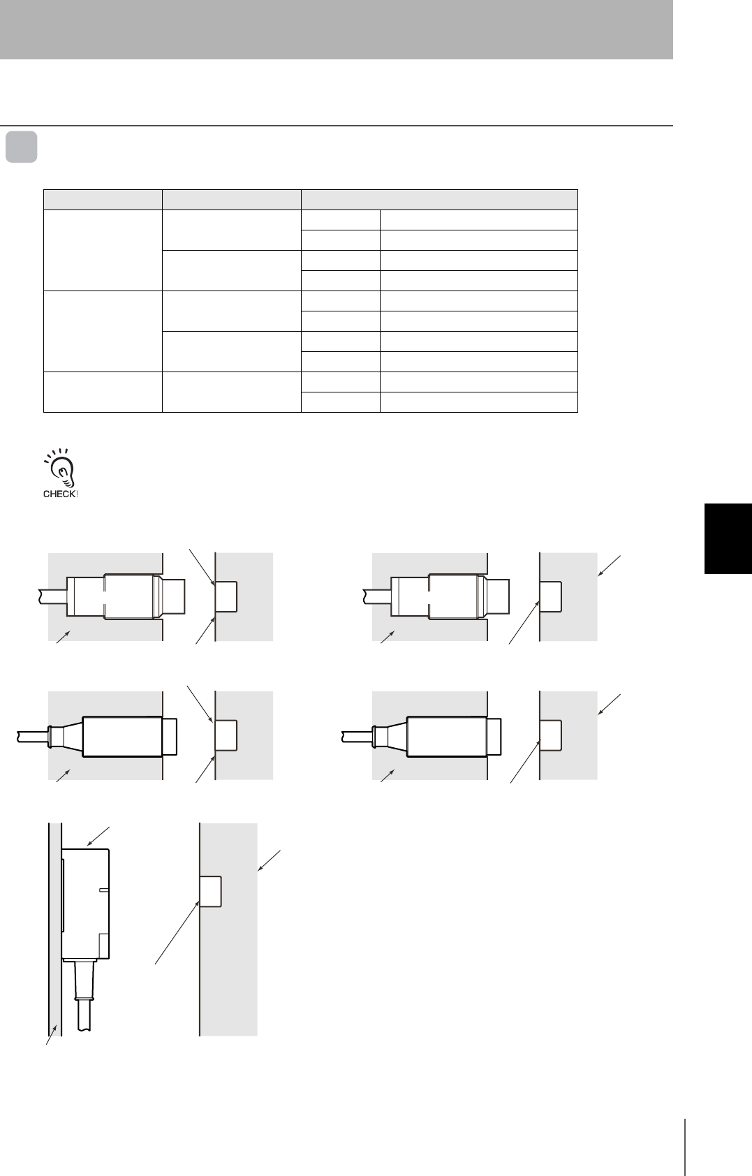
RFID System
User's Manual
87
Section 6 Characteristics
Section 6
Appendices
Characteristics
Communications Distance Specifications
V680-D1KP52MT
When embedding the V680-D1KP52MT into a metal surface, use the V680-HS51/-HS52 Antenna.
Transmission will not be possible if the V680-HS63 Antenna is used.
Measurement Conditions
Antenna ID Tag Communications distance
V680-HS51
V680-D1KP52MT Read 0.5 to 6.5 mm (Axis offset: ±2)
Write 0.5 to 6.0 mm (Axis offset: ±2)
V680-D1KP52MT
embedded in metal (steel)
Read 0.5 to 3.5 mm (Axis offset: ±2)
Write 0.5 to 3.0 mm (Axis offset: ±2)
V680-HS52
V680-D1KP52MT Read 0.5 to 9.0 mm (Axis offset: ±2)
Write 0.5 to 8.5 mm (Axis offset: ±2)
V680-D1KP52MT
embedded in metal (steel)
Read 0.5 to 4.5 mm (Axis offset: ±2)
Write 0.5 to 4.0 mm (Axis offset: ±2)
V680-HS63 V680-D1KP52MT Read 0.5 to 12.0 mm (Axis offset: ±2)
Write 0.5 to 9.5 mm (Axis offset: ±2)
V680-D1KP52MT
V680-HS51 V680-HS51
V680-D1KP52MT
V680-D1KP52MT
V680-D1KP52MT
V680-D1KP52MT
V680-HS63
Non-metallic material
Non-metallic material Non-metallic material
Metallic material
Metallic material
Metallic
material
Metallic
material
Non-metallic material
(Examples: Resin, plastic, wood, etc.)
Non-metallic material
(Examples: Resin, plastic, wood, etc.)
V680-HS52 V680-HS52
Non-metallic material
(Examples: Resin, plastic, wood, etc.)
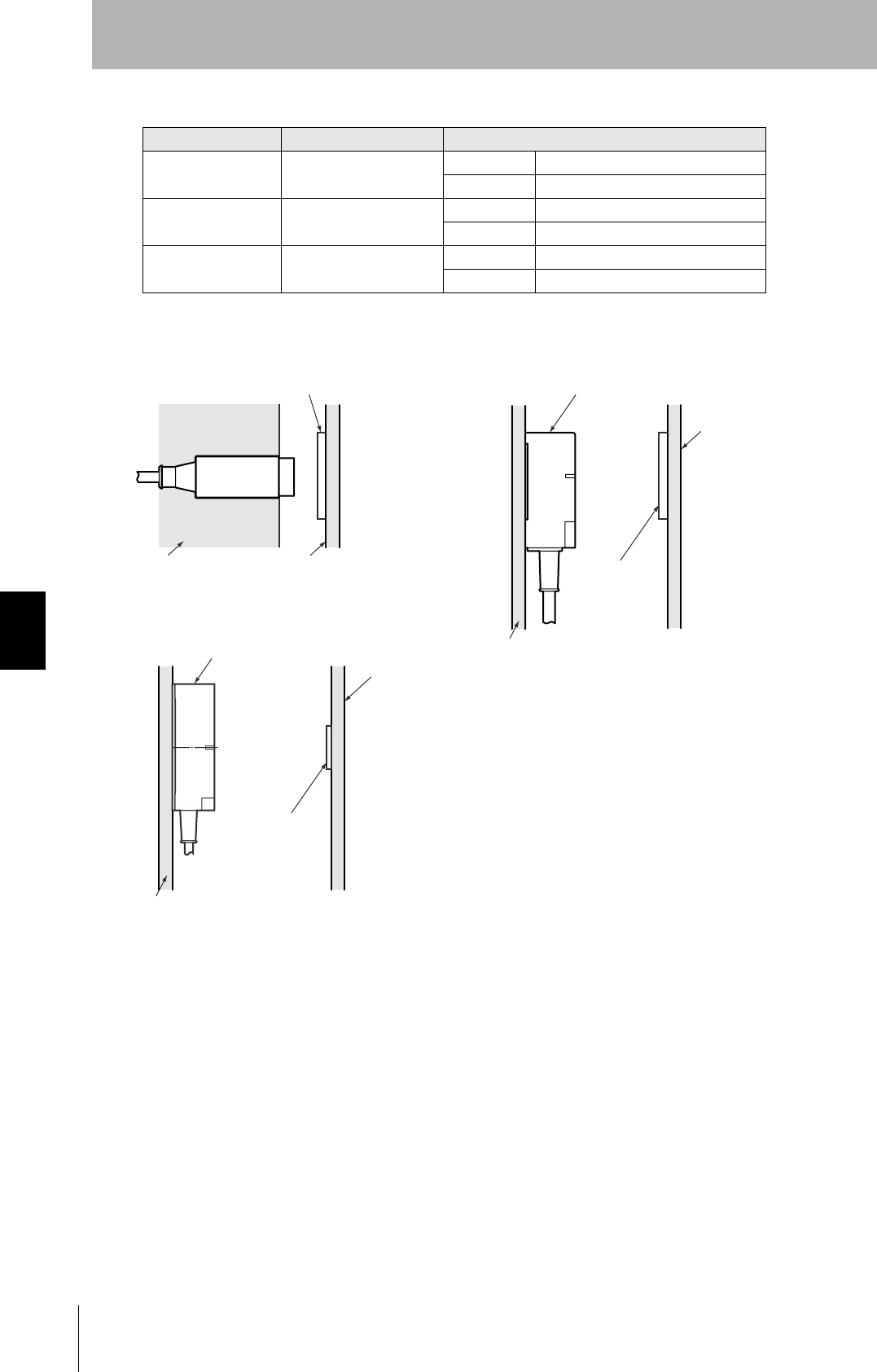
88
Section 6 Characteristics
RFID System
User's Manual
Section 6
Appendices
V680-D1KP66T
Measurement Conditions
Antenna ID Tag Communications distance
V680-HS52 V680-D1KP66T Read 1.0 to 17.0 mm (Axis offset: ±2)
Write 1.0 to 17.0 mm (Axis offset: ±2)
V680-HS63 V680-D1KP66T Read 5.0 to 30.0 mm (Axis offset: ±10)
Write 5.0 to 25.0 mm (Axis offset: ±10)
V680-HS65 V680-D1KP66T Read 5.0 to 47.0 mm (Axis offset: ±10)
Write 5.0 to 42 mm (Axis offset: ±10)
V680-D1KP66T
V680-HS52
Non-metallic material Non-metallic material
(Examples: Resin, plastic, wood, etc.)
V680-HS63
Non-metallic material
(Examples: Resin, plastic,
wood, etc.)
V680-D1KP66T
Non-metallic material
Non-metallic material
Non-metallic material
(Examples: Resin, plastic, wood, etc.)
V680-D1KP66T
V680-HS65

RFID System
User's Manual
89
Section 6 Characteristics
Section 6
Appendices
V680-D1KP66MT
Measurement Conditions
Antenna ID Tag Communications distance
V680-HS52 V680-D1KP66MT
embedded in metal (steel)
Read 1.0 to 16.0 mm (Axis offset: ±2)
Write 1.0 to 14.0 mm (Axis offset: ±2)
V680-HS63 V680-D1KP66MT
embedded in metal (steel)
Read 5.0 to 25.0 mm (Axis offset: ±10)
Write 5.0 to 20.0 mm Axis offset: ±10)
V680-HS65 V680-D1KP66MT
embedded in metal (steel)
Read 5.0 to 25.0 mm (Axis offset: ±10)
Write 5.0 to 20.0 mm (Axis offset: ±10)
V680-D1KP66MT
V680-HS52
Non-metallic material Non-metallic material
(Examples: Resin, plastic, wood, etc.)
V680-HS63
Metallic material
V680-D1KP66MT
Non-metallic material
Non-metallic material
Metallic material
V680-D1KP66MT
V680-HS65
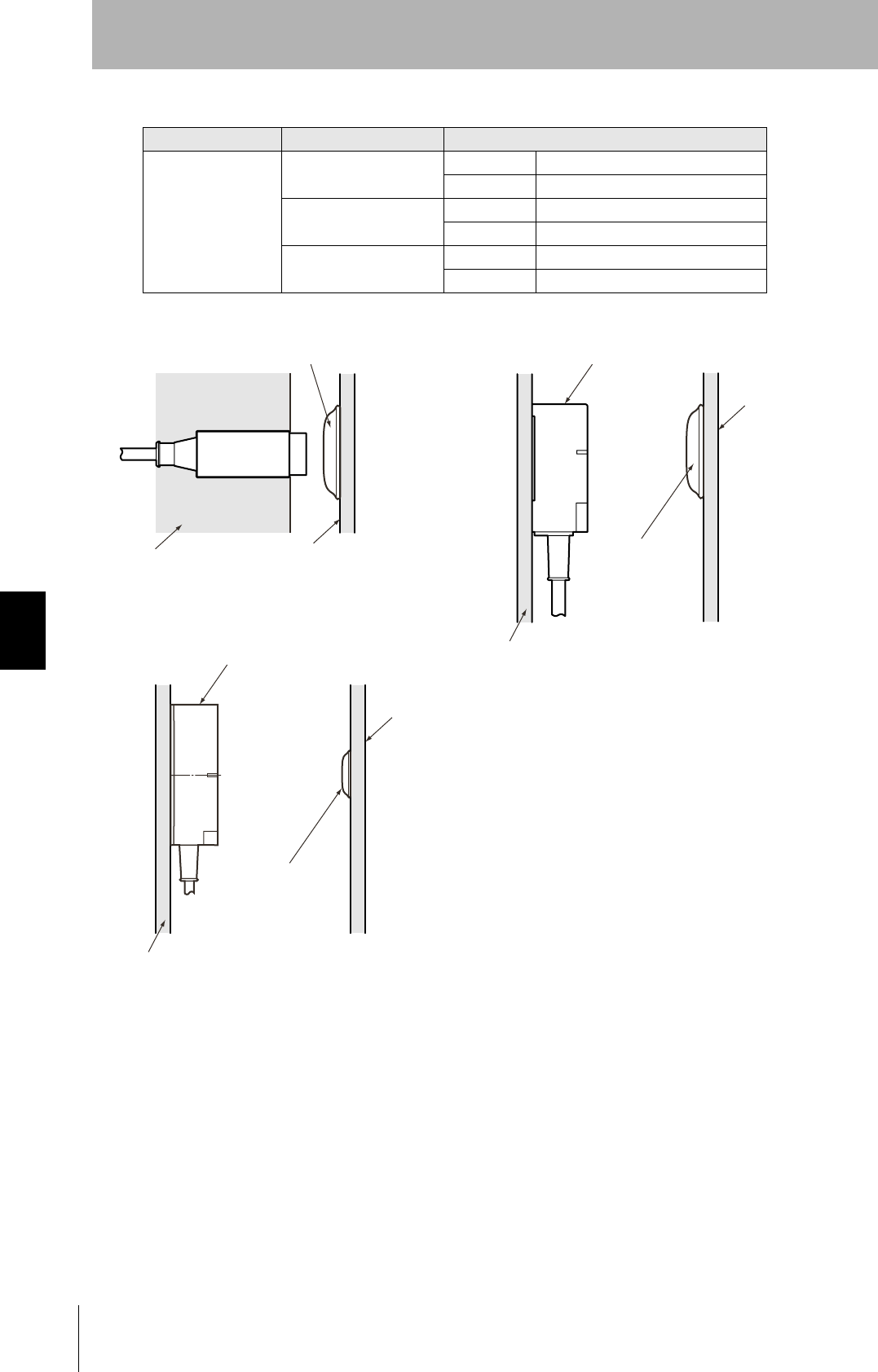
90
Section 6 Characteristics
RFID System
User's Manual
Section 6
Appendices
V680-D1KP66-SP
Measurement Conditions
Antenna ID Tag Communications distance
V680-HA63A
V680-HS52 Read 0 to 15.0 mm (Axis offset: ±2)
Write 0 to 15.0 mm (Axis offset: ±2)
V680-HS63 Read 0 to 25.0 mm (Axis offset: ±10)
Write 0 to 20.0 mm (Axis offset: ±10)
V680-HS65 Read 0 to 42.0 mm (Axis offset: ±10)
Write 0 to 37.0 mm (Axis offset: ±10)
V680-D1KP66T-SP
V680-HS52
Non-metallic material Metallic material
(Examples: Resin, plastic, wood, etc.)
V680-D1KP66T-SP
V680-HS63
Non-metallic material
Metallic material
(Examples: Resin,
plastic, wood, etc.)
Metallic material
(Examples: Resin, plastic, wood, etc.)
Non-metallic material
V680-D1KP66T-SP
V680-HS65
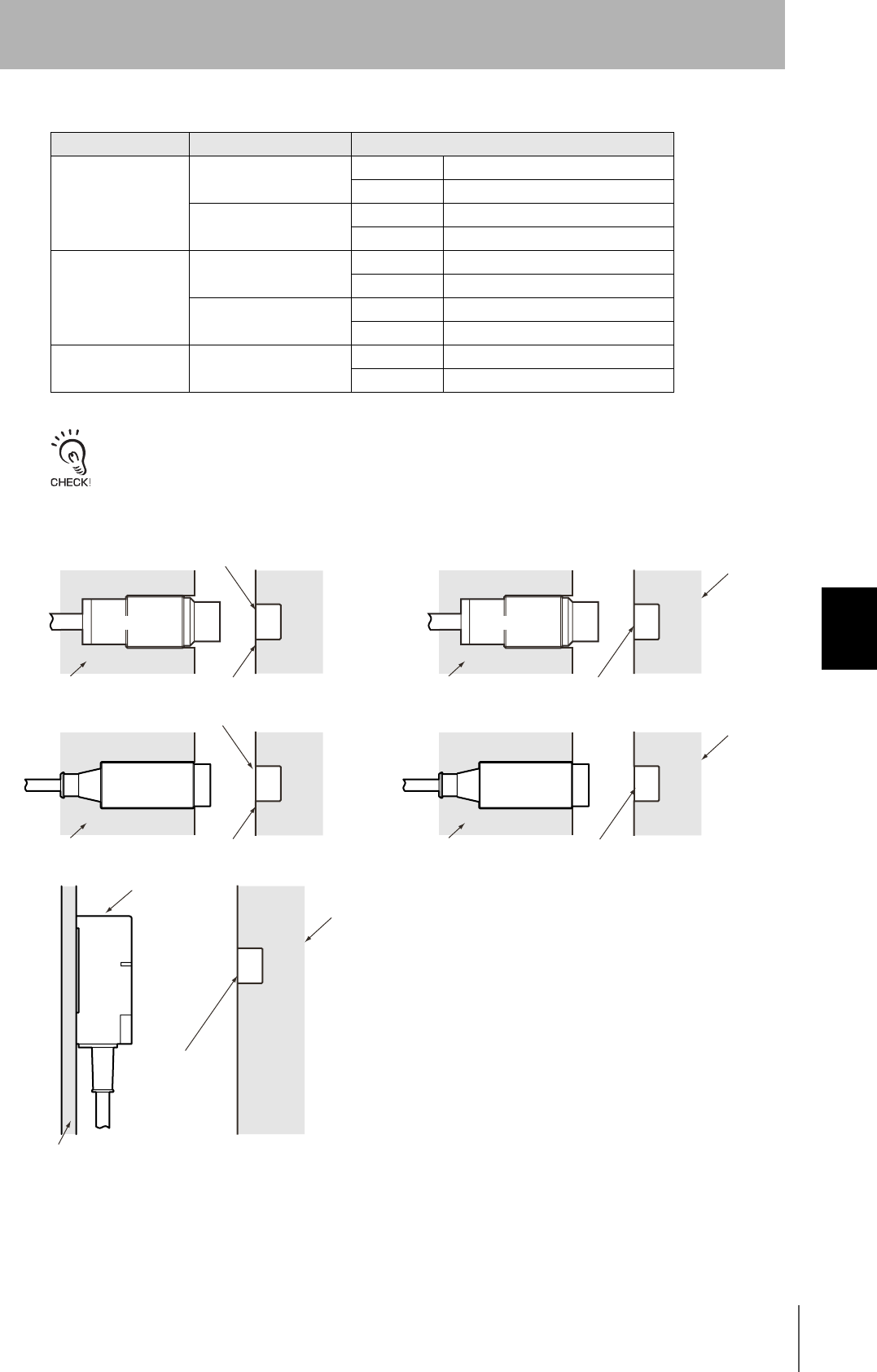
RFID System
User's Manual
91
Section 6 Characteristics
Section 6
Appendices
V680-D2KF52M
When embedding the V680-D2KP52M into a metal surface, use the V680-HS51/-HS52 Antenna.
Transmission will not be possible if the V680-HS63 Antenna is used.
Measurement Conditions
Antenna ID Tag Communications distance
V680-HS51
V680-D2KF52M Read 0.5 to 5.5 mm (Axis offset: ±2)
Write 0.5 to 5.5 mm (Axis offset: ±2)
V680-D2KF52M
embedded in metal (steel)
Read 0.5 to 3.5 mm (Axis offset: ±2)
Write 0.5 to 3.5 mm (Axis offset: ±2)
V680-HS52
V680-D2KF52M Read 0.5 to 8.0 mm (Axis offset: ±2)
Write 0.5 to 8.0 mm (Axis offset: ±2)
V680-D2KF52M
embedded in metal (steel)
Read 0.5 to 3.0 mm (Axis offset: ±2)
Write 0.5 to 3.0 mm (Axis offset: ±2)
V680-HS63 V680-D2KF52M Read 0.5 to 9.5 mm (Axis offset: ±2)
Write 0.5 to 9.5 mm (Axis offset: ±2)
V680-D2KP52M
V680-HS51 V680-HS51
V680-D2KP52M
V680-D2KP52M
V680-D1KP52M
V680-D2KP52M
V680-HS63
Non-metallic material
Non-metallic material Non-metallic material
Metallic material
Metallic material
Metallic
material
Metallic
material
Non-metallic material
(Examples: Resin, plastic, wood, etc.)
Non-metallic material
(Examples: Resin, plastic, wood, etc.)
V680-HS52 V680-HS52
Non-metallic material
(Examples: Resin, plastic, wood, etc.)
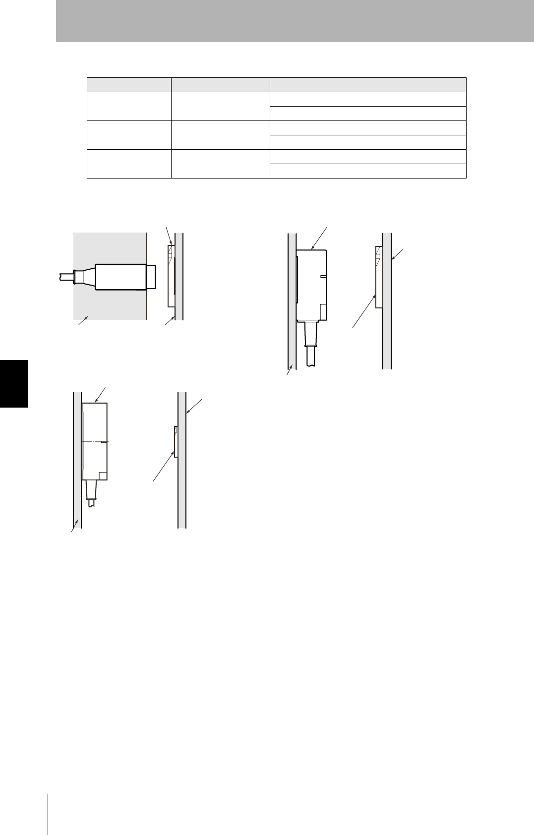
92
Section 6 Characteristics
RFID System
User's Manual
Section 6
Appendices
V680-D2KF67
Measurement Conditions
Antenna ID Tag Communications distance
V680-HS52 V680-D2KF67 Read 7.0 to 30.0 mm (Axis offset: ±2)
Write 7.0 to 30.0 mm (Axis offset: ±2)
V680-HS63 V680-D2KF67 Read 7.0 to 30.0 mm (Axis offset: ±10)
Write 7.0 to 30.0 mm (Axis offset: ±10)
V680-HS65 V680-D2KF67 Read 5.0 to 42.0 mm (Axis offset: ±10)
Write 5.0 to 42.0 mm (Axis offset: ±10)
V680-D2KF67M
V680-HS52
Non-metallic material Metallic material
V680-HS63
V680-D2KF67M
Non-metallic material
Non-metallic material
V680-D2KF67M
Non-metallic material
(Examples: Resin, plastic, wood, etc.)
V680-HS65
Metallic material
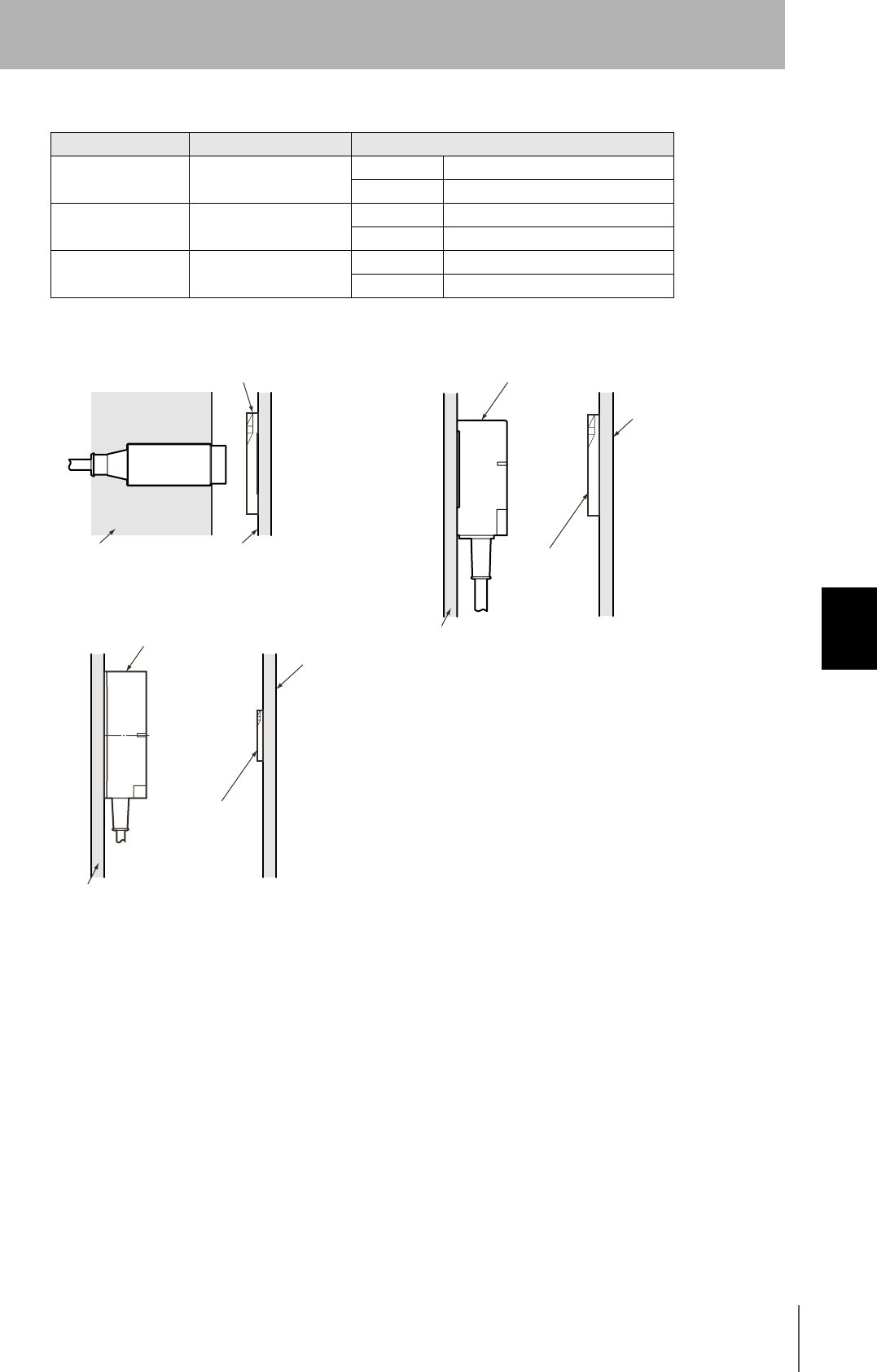
RFID System
User's Manual
93
Section 6 Characteristics
Section 6
Appendices
V680-D2KF67M
Measurement Conditions
Antenna ID Tag Communications distance
V680-HS52 V680-D2KF67M
embedded in metal (steel)
Read 6.0 to 25.0 mm (Axis offset: ±2)
Write 6.0 to 25.0 mm (Axis offset: ±2)
V680-HS63 V680-D2KF67M
embedded in metal (steel)
Read 6.0 to 25.0 mm (Axis offset: ±10)
Write 6.0 to 25.0 mm (Axis offset: ±10)
V680-HS65 V680-D2KF67M
embedded in metal (steel)
Read 5.0 to 25.0 mm (Axis offset: ±10)
Write 5.0 to 25.0 mm (Axis offset: ±10)
V680-D2KF67M
V680-HS52
Non-metallic material Metallic material
V680-HS63
V680-D2KF67M
Non-metallic material
Non-metallic material
V680-D2KF67M
Non-metallic material
(Examples: Resin, plastic, wood, etc.)
V680-HS65
Metallic material

94
Section 6 Characteristics
RFID System
User's Manual
Section 6
Appendices
V680-D8KF68/-D32KF68
Measurement Conditions
Antenna ID Tag Communications distance
V680-HS63
V680-D8KF68 Read 5.0 to 45.0 mm (Axis offset: ±2)
Write 5.0 to 45.0 mm (Axis offset: ±2)
V680-D8KF68
(with ATTACHMENT, V680-A81) with metal on back surface (steel)
Read 5.0 to 35.0 mm (Axis offset: ±10)
Write 5.0 to 35.0 mm (Axis offset: ±10)
V680-D32KF68 Read 5.0 to 45.0 mm (Axis offset: ±10)
Write 5.0 to 45.0 mm (Axis offset: ±10)
V680-D32KF68
(with ATTACHMENT, V680-A81) with metal on back surface (steel)
Read 5.0 to 35.0 mm (Axis offset: ±10)
Write 5.0 to 35.0 mm (Axis offset: ±10)
V680-HS65
V680-D8KF68 Read 5.0 to 75.0 mm (Axis offset: ±2)
Write 5.0 to 75.0 mm (Axis offset: ±2)
V680-D8KF68
(with ATTACHMENT, V680-A81) with metal on back surface (steel)
Read 5.0 to 55.0 mm (Axis offset: ±10)
Write 5.0 to 55.0 mm (Axis offset: ±10)
V680-D32KF68 Read 5.0 to 75.0 mm (Axis offset: ±10)
Write 5.0 to 75.0 mm (Axis offset: ±10)
V680-D32KF68
(with ATTACHMENT, V680-A81) with metal on back surface (steel)
Read 5.0 to 55.0 mm (Axis offset: ±10)
Write 5.0 to 55.0 mm (Axis offset: ±10)
V680-D8KF68/-D32KF68
Metallic material
Non-metallic material
(Examples: Resin, plastic, wood, etc.)
V680-HS65
Metallic material
Metallic material Metallic material
Non-metallic material
(Examples: Resin, plastic, wood, etc.)
Non-metallic material
(Examples: Resin, plastic, wood, etc.)
Non-metallic material
(Examples: Resin, plastic, wood, etc.)
V680-D8KF68/-D32KF68
V680-HS65
V680-D8KF68
V680-D32KF68
V680-D8KF68
V680-D32KF68
V680-A81
(ATTACHMENT)
V680-A81
(ATTACHMENT)
V680-HS63
V680-HS63
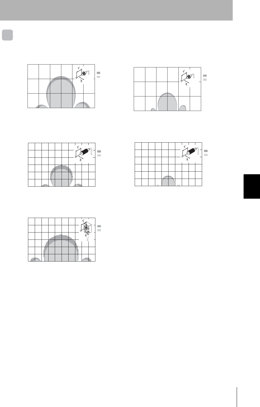
RFID System
User's Manual
95
Section 6 Characteristics
Section 6
Appendices
Communications Area
680-D1KP52MT
● V680-HS51 and V680-D1KP52MT ● V680-HS51 and V680-D1KP52MT
(Embedded in Metal: Steel)
● V680-HS52 and V680-D1KP52MT ● V680-HS52 and V680-D1KP52MT
(Embedded in Metal: Steel)
● V680-HS63 and V680-D1KP52MT
X Axis (Unit: mm)
Read
Write
15
10
5
0−15 151050−5−10
Y Axis
X Axis (Unit: mm)
Read
Write
15
10
5
0−15 151050−5−10
Y Axis
X Axis (Unit: mm)
Read
Write
15
10
5
0−15 151050−5−10
Y Axis
X Axis (Unit: mm)
Read
Write
15
10
5
0−15 151050−5−10
Y Axis
X Axis (Unit: mm)
Read
Write
15
10
5
0−15 151050−5−10
Y Axis
96
Section 6 Characteristics
RFID System
User's Manual
Section 6
Appendices
V680-D1KP66T
V680-D1KP66MT
● V680-HS52 and V680-D1KP66T ● V680-HS63 and V680-D1KP66T
● V680-HS65 and V680-D1KP66T
● V680-HS52 and V680-D1KP66MT
with Metal on Back Surface (Steel)
● V680-HS63 and V680-D1KP66MT
with Metal on Back Surface (Steel)
● V680-HS65 and V680-D1KP66MT
with Metal on Back Surface (Steel)
X Axis (Unit: mm)
Read
Write
60
40
20
0
−50 5030100−10−30
Y Axis
50
30
10
−40 −20 4020
X Axis (Unit: mm)
Read
Write
60
40
20
0
−50 5030100−10−30
Y Axis
50
30
10
−40 −20 4020
X Axis (Unit: mm)
Read
Write
60
40
20
0
−100 10060200−20−60
Y Axis
50
30
10
−80 −40 8040
X Axis (Unit: mm)
Read
Write
60
40
20
0
−50 5030100−10−30
Y Axis
50
30
10
−40 −20 4020
X Axis (Unit: mm)
Read
Write
60
40
20
0
−50 5030100−10−30
Y Axis
50
30
10
−40 −20 4020
X Axis (Unit: mm)
Read
Write
60
40
20
0
−100 10060200−20−60
Y Axis
50
30
10
−80 −40 8040
RFID System
User's Manual
97
Section 6 Characteristics
Section 6
Appendices
V680-D1KP66T-SP
● V680-HS52 and V680-D1KP66T-SP ● V680-HS63 and V680-D1KP66T-SP
● V680-HS65 and V680-D1KP66T-SP
Y
X
X Axis (Unit: mm)
Read
Write
60
40
20
0
−50 5030100−10−30
Y Axis
50
30
10
−40 −20 4020
Y
X
X Axis (Unit: mm)
Read
Write
60
40
20
0
−50 5030100
−10−30
Y Axis
50
30
10
−40 −20 4020
Y
X
X Axis (Unit: mm)
Read
Write
60
40
20
0
−100 10060200−20−60
Y Axis
50
30
10
−80 −40 8040

98
Section 6 Characteristics
RFID System
User's Manual
Section 6
Appendices
V680-D2KF52M
● V680-HS51 and V680-D2KF52M ● V680-HS51 and V680-D2KF52M
(Embedded in Metal: Steel)
● V680-HS52 and V680-D2KP52M ● V680-HS52 and V680-D2KF52M
(Embedded in Metal: Steel)
● V680-HS63 and V680-D2KP52M
X Axis (Unit: mm)
Read/Write
15
10
5
0−15 151050−5−10
Y Axis
X Axis (Unit: mm)
15
10
5
0−15 151050−5−10
Y Axis
Read/Write
X Axis (Unit: mm)
15
10
5
0−15 151050−5−10
Y Axis
Read/Write
X Axis (Unit: mm)
15
10
5
0−15 151050−5−10
Y Axis
Read/Write
X Axis (Unit: mm)
15
10
5
0−15 151050−5−10
Y Axis
Read/Write
RFID System
User's Manual
99
Section 6 Characteristics
Section 6
Appendices
V680-D2KF67
V680-D2KF67M
● V680-HS52 and V680-D2KF67 ● V680-HS63 and V680-D2KF67
● V680-HS65 and V680-D2KF67
● V680-HS52 and V680-D2KF67M
with Metal on Back Surface (Steel)
● V680-HS63 and V680-D2KF67M
with Metal on Back Surface (Steel)
● V680-HS65 and V680-D2KF67M
with Metal on Back Surface (Steel)
X Axis (Unit: mm)
Read/Write
70
50
30
0
6040200−20
Y Axis
60
40
10
−60 −40
20
X Axis (Unit: mm)
Read/Write
70
50
30
0
6040200−20
Y Axis
60
40
10
−60 −40
20
X Axis (Unit: mm)
100
60
20
0
−100 10060200−20−60
Y Axis
80
40
−80 −40 8040
Read/Write
X Axis (Unit: mm)
Read/Write
70
50
30
0
6040200−20
Y Axis
60
40
10
−60 −40
20
X Axis (Unit: mm)
Read/Write
70
50
30
0
6040200−20
Y Axis
60
40
10
−60 −40
20
X Axis (Unit: mm)
Read/Write
100
60
20
0
−100 10060200−20−60
Y Axis
80
40
−80 −40 8040
100
Section 6 Characteristics
RFID System
User's Manual
Section 6
Appendices
V680-D8KF68/-D32KF68
● V680-HS63 and V680-D8KF68/-D32KF68
(Horizontal-facing ID Tag)
● V680-HS63 and V680-D8KF68/-D32KF68
(Vertical-facing ID Tag)
● V680-HS63 and V680-D8KF68/-D32KF68
(with Attachment, V680-A81)
Metal on back: Steel (Vertical-facing ID Tag)
● V680-HS63 and V680-D8KF68/-D32KF68
(with Attachment, V680-A81)
Metal on back: Steel (Vertical-facing ID Tag)
● V680-HS65 and V680-D8KF68/-D32KF68
(Horizontal-facing ID Tag)
● V680-HS65 and V680-D8KF68/-D32KF68
(Vertical-facing ID Tag)
● V680-HS65 and V680-D8KF68/-D32KF68
(with Attachment, V680-A81)
Metal on back: Steel (Vertical-facing ID Tag)
● V680-HS65 and V680-D8KF68/-D32KF68
(with Attachment, V680-A81)
Metal on back: Steel (Vertical-facing ID Tag)
X Axis (Unit: mm)
Read/Write
80
60
40
0
6040200−20
Y Axis
−60 −40
20
−80 80
X Axis (Unit: mm)
Read/Write
80
60
40
0
6040200−20
Y Axis
−60 −40
20
−80 80
X Axis (Unit: mm)
Read/Write
80
60
40
0
6040200−20
Y Axis
−60 −40
20
−80 80
X Axis (Unit: mm)
Read/Write
80
60
40
0
6040200−20
Y Axis
−60 −40
20
−80 80
X Axis (Unit: mm)
Read/Write
120
80
40
0
−120
12080200
−20−80
Y Axis
100
60
20
−100 −40
10040 60
−60
X Axis (Unit: mm)
Read/Write
120
80
40
0
−120
12080200
−20−80
Y Axis
100
60
20
−100 −40
10040 60
−60
X Axis (Unit: mm)
Read/Write
120
80
40
0
−120
12080200
−20−80
Y Axis
100
60
20
−100 −40
10040 60
−60
X Axis (Unit: mm)
Read/Write
120
80
40
0
−120
12080200
−20−80
Y Axis
100
60
20
−100 −40
10040 60
−60

RFID System
User's Manual
101
Section 6 Characteristics
Section 6
Appendices
Communications Time
The communications time is the time required for communications between the Antenna and the ID
Tag. The communications time of the DeviceNet Remote ID Controller is longer when data is being
written.
Communications Time Specifications
ID Tag Travel Speed
The travel time (i.e., conveyor speed) of an ID Tag on the line can be calculated by finding the
communications area and communications time for the I/O Sensor ID.
Data Read Calculation Example
Model V680-HAM91/V680-HAM81
Read Write
Function Data write mode
Verify read mode Byte mode Bit set mode
Bit clear mode
ID Tag
type
EEPROM type zz ms zz ms zz ms
FRAM type zz ms zz ms zz ms
Note 1: The travel speed depends on communications distance Y and axis offset. It is recommended to refer to the
communications area diagram and use the part with the widest area.
2. These values are guidelines. Perform testing with the actual device before operation.
3. Processing for communications errors is not included in this formula.
ID Tag travel speed (i.e., conveyor speed) = Communications time
Travel distance (x) in communications area
ID Tag travel speed (m/min.) = ▲▲ (ms)
zz (mm)
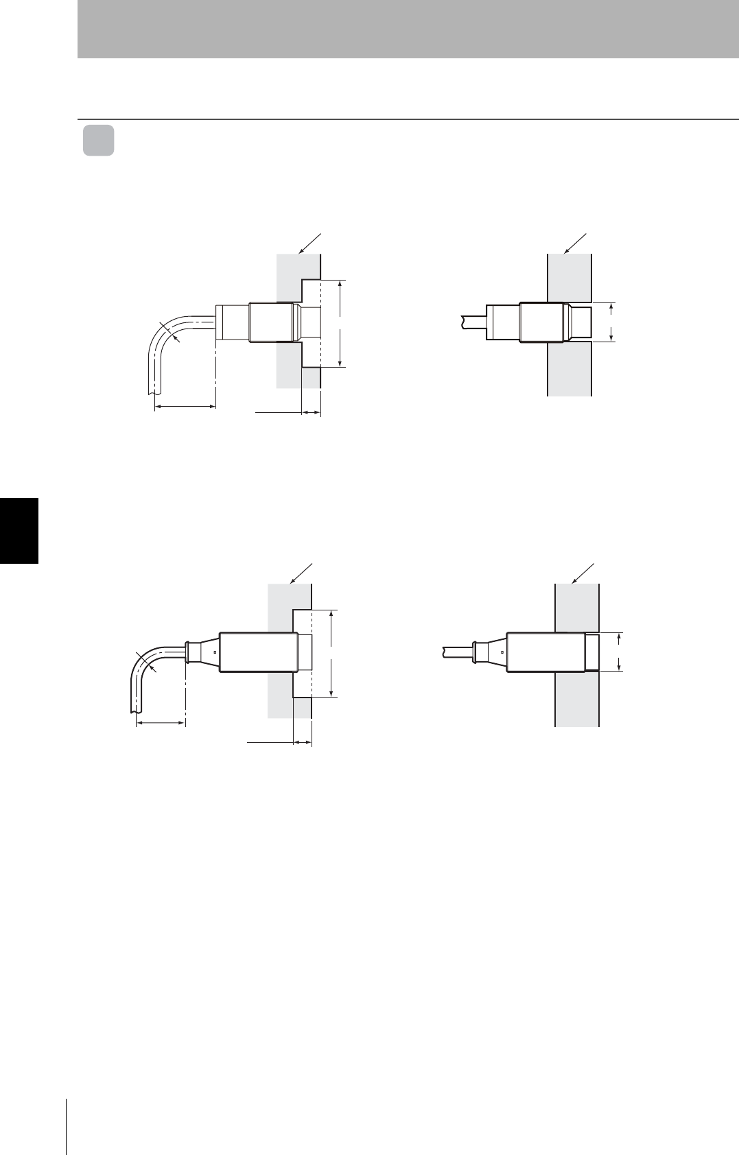
102
Section 6 Reference Data
RFID System
User's Manual
Section 6
Appendices
Reference Data
Effect of Surrounding Metals on the Antenna (Reference)
V680-HS51
When embedding the Antenna in metal, be sure the metal does not extend beyond the
communications section (coil surface) of the Antenna.
V680-HS52
When embedding the Antenna in metal, be sure the metal does not extend beyond the
communications section (coil surface) of the Antenna.
Surrounding metal
(steel)
Surrounding metal
(steel)
40 mm min. 7 mm min.
R18 min.
Antenna
120 (±60) mm dia. min. 12 mm dia.
Communications
distance reduced
by approx. 50%.
Do not bend the cable into a curve tighter
than 18 mm in radius.
If the metal around the Antenna reaches the coil surface, the
communications distance will be reduced by approx. 50% compared
with mounting to a non-metallic surface.
Antenna
Surrounding metal
(steel)
Surrounding metal
(steel)
60 mm min.
15 mm min.
R22 min.
AntennaAntenna
130 (±65) mm dia. min. 22 mm dia.
Communications
distance reduced
by approx. 50%.
Do not bend the cable into a curve tighter
than 22 mm in radius.
If the metal around the Antenna reaches the coil surface, the
communications distance will be reduced by approx. 50% compared
with mounting to a non-metallic surface.
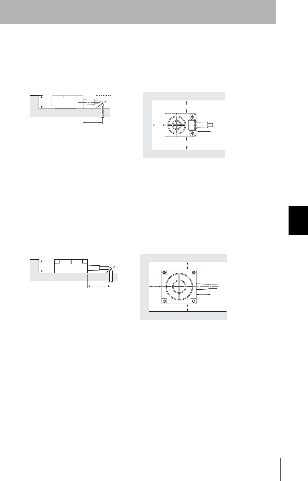
RFID System
User's Manual
103
Section 6 Reference Data
Section 6
Appendices
V680-HS63
In addition to surface mounting, it is also possible to embed the V680-HS63 in a metal casing to protect
it from being struck by other objects. To prevent malfunctioning, allow a space of at least 30 mm
between the Antenna and the sides of the metal casing. If the space is less than 30 mm, the read/write
distance will be greatly diminished. In addition, the height of metal casing must not exceed that of the
Antenna.
Note 1: Do not bend the cable into a curve tighter than 22 mm in radius.
2: The communications distance will be reduced significantly if the Antenna is installed closer
than 30 mm to metal surfaces.
V680-HS65
In addition to surface mounting, it is also possible to embed the V680-HS65 in a metal casing to protect
it from being struck by other objects. To prevent malfunctioning, allow a space of at least 100 mm
between the Antenna and the sides of the metal casing. If the space is less than 100 mm, the read/
write distance will be greatly diminished. In addition, the height of metal casing must not exceed that of
the Antenna.
Note 1: Do not bend the cable into a curve tighter than 22 mm in radius.
2: The communications distance will be reduced significantly if the Antenna is installed closer
than 100 mm to metal surfaces.
60 mm min.
30 mm min.
30 mm
min. 30 mm min.
30 mm min.
Metal casing
Metal casing
R22 min.
23 mm
max.
60 mm min.
100 mm min.
100 mm
min.
100 mm min.
100 mm min.
Metal casing
Metal casing
R22 min.
30 mm
max.
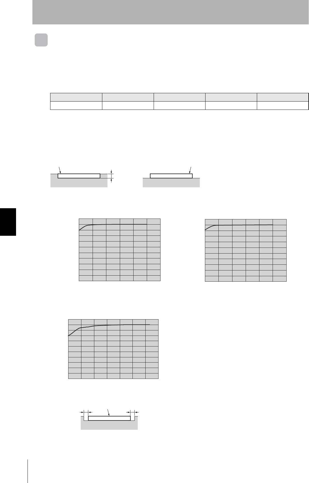
104
Section 6 Reference Data
RFID System
User's Manual
Section 6
Appendices
Effect of Surrounding Metals on the ID Tags
V680-D1KP52MT
Differences in Surrounding Metals
Communications distances are affected by the type of metal in back of or surrounding the Tag, as
shown in the following table.
V680-D1KP66MT
Effect of Surrounding Metals (Reference)
The V680-D1KP66MT can be surface-mounted or it can be embedded in metal. If it is embedded in
metal, the height of the metal casing must not exceed that of the Tag.
Steel SUS Brass Aluminum
V680-D2KF52M 100% 85% to 90% 80% to 85% 80% to 85%
Note: The value for steel around or behind the Tag is set to 100%.
● V680-HS52 and V680-D1KP66MT ● V680-HS63 and V680-D1KP66MT
● V680-HS65 and V680-D1KP66MT
Embedded
ID Tag ID Tag
Surface-mounted
Metal casing Metal casing
3.5 mm max.
The communications distance
without metal is 100%
Distance to metal (x)
(mm)
100
80
20
050302010
90
30
10
40
(%)
50
60
40
70
The communications distance
without metal is 100%
Distance to metal (x)
(mm)
100
80
20
050302010
90
30
10
40
(%)
50
60
40
70
The communications distance
without metal is 100%
Distance to metal (x)
(mm)
100
80
20
050302010
90
30
10
40
(%)
50
60
40
70
60
ID Tag
Metal casing
XX
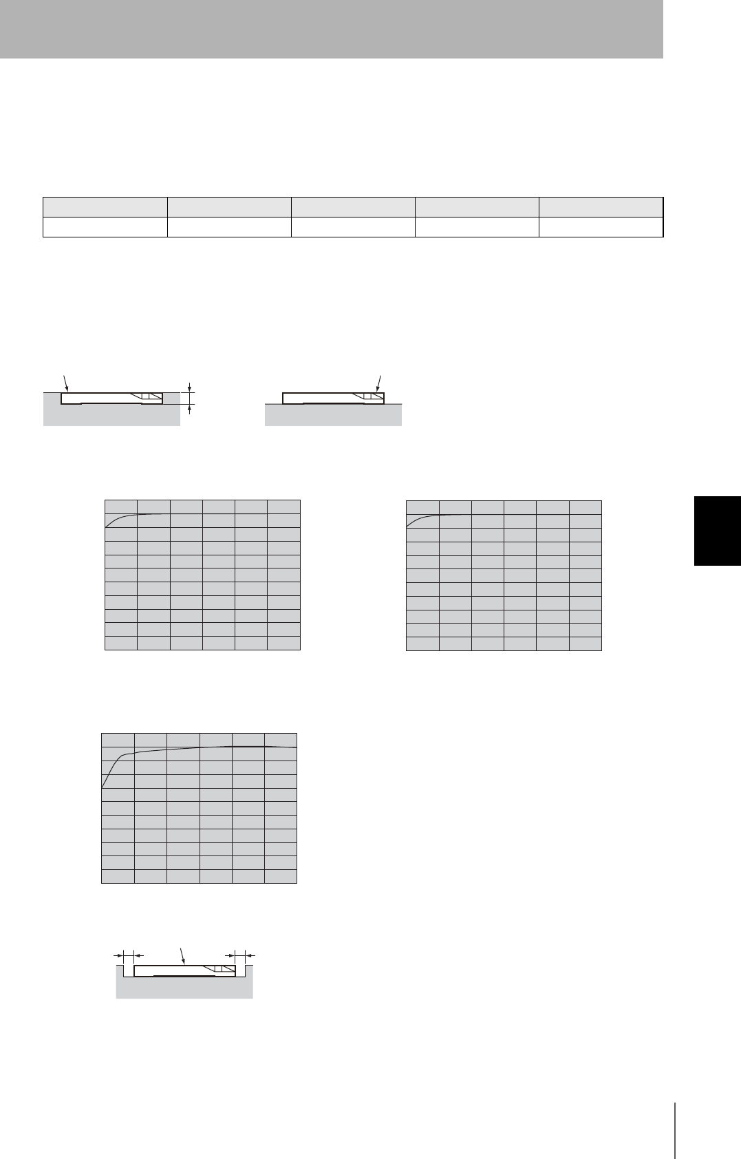
RFID System
User's Manual
105
Section 6 Reference Data
Section 6
Appendices
V680-D2KF52M
Differences in Surrounding Metals
Communications distances are affected by the type of metal in back of or surrounding the Tag, as
shown in the following table.
V680-D2KF67M
Effect of Surrounding Metals (Reference)
The V680-D2KF67M can be surface-mounted or it can be embedded in metal. If it is embedded in
metal, the height of the metal casing must not exceed that of the Tag.
Steel SUS Brass Aluminum
V680-D2KF52M 100% 80% to 85% 80% to 85% 75% to 80%
Note: The value for steel around or behind the Tag is set to 100%.
● V680-HS52 and V680-D2KF67M ● V680-HS63 and V680-D2KF67M
● V680-HS65 and V680-D2KF67M
Embedded
ID Tag
Surface-mounted
Metal casing Metal casing
4.5 mm max.
ID Tag
0
10
20
30
40
50
60
70
80
90
100
10 20 30 40 50 (mm)
The communications distance
without metal is 100%
Distance to metal (x)
(%)
0
10
20
30
40
50
60
70
80
90
100
10 20 30 40 50 (mm)
The communications distance
without metal is 100%
Distance to metal (x)
(%)
0
10
20
30
40
50
60
70
80
90
100
10 20 30 40 50 (mm)
The communications distance
without metal is 100%
Distance to metal (x)
(%)
Metal casing
Tag
XX
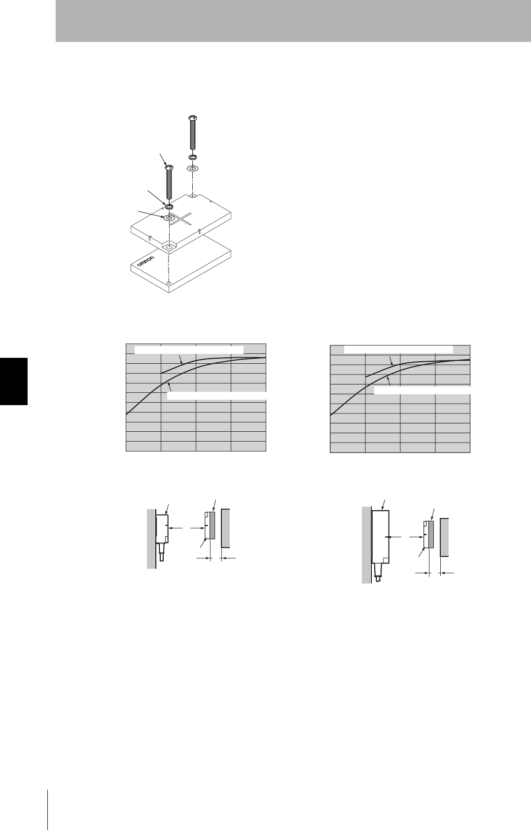
106
Section 6 Reference Data
RFID System
User's Manual
Section 6
Appendices
V680-D8KF67/-D32KF68
Effect of Surrounding Metals (Reference)
•Special Attachment (V680-A81) Installation Direction
● V680-HS63 and V680-D8KF68/-D32KF68 ● V680-HS65 and V680-D8KF68/-D32KF68
V680-A81
ATTACHMENT
MADE IN JAPAN
M4 screw
Spring washer
Flat washer The transmission distance will be reduced if there is metal in back of
a Tag. When mounting on a metal surface, use the special
Attachment (V680-A81) of another sales or insert a non-metallic
spacer (e.g., plastic, wood, etc.).
0
10
20
30
40
50
60
70
80
90
100
10 20 30 40
(mm)
(%)
The communications distance
without metal is 100%.
Distance to metal (x)
When Attachment (V680-A81) is not used
When Attachment (V680-A81) is used
0
10
20
30
40
50
60
70
80
90
100
10 20 30 40
(mm)
(%) When Attachment (V680-A81) is used
When Attachment (V680-A81) is not used
Distance to metal (x)
The communications distance
without metal is 100%
X
Y
Antenna Attachment
Tag
Metal
Communica-
tions
distance
Metal on back
X
Y
Antenna
Attachment
Tag
Metal
Communica-
tions
distance
Metal on back
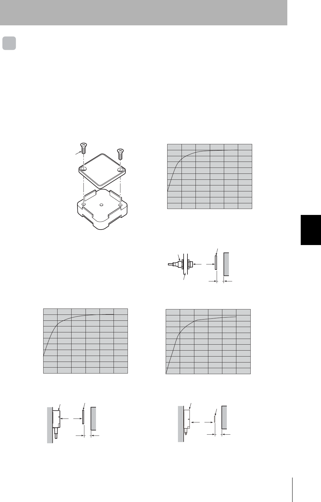
RFID System
User's Manual
107
Section 6 Reference Data
Section 6
Appendices
Effect of Metal behind Tags (Reference)
V680-D1KP66T
Effect of Metal behind Tags (Reference)
The V680-D1KP66T communications distance is reduced if there is any metal material behind the Tag.
If the Tag is to be mounted to metal, then either use a V600-A86 Attachment (sold separately) or insert
a non-metal spacer (such as plastic or resin). The relationship between the distance from the Tag to
the metal surface and the communications distance is shown below.
The Attachment is 10 mm thick, and more than one Attachment can be stacked.
V600-A86 Attachment Installation ● V680-HS52 and V680-D1KP66T
Note: Install so that the mounting holes are aligned.
● V680-HS63 and V680-D1KP66T ● V680-HS65 and V680-D1KP66T
M3 countersunk screw
Distance to metal (x)
10
20
30
40
50
60
70
80
90
100
(%)
The communications distance
without metal is 100%
010203040 (mm)
50
Antenna
ID Tag
Metal X
YMetal on back
Communica-
tions
distance
Distance to metal (x)
10
20
30
40
50
60
70
80
90
100
(%)
The communications distance
without metal is 100%
010203040 (mm)
50
Distance to metal (x)
10
20
30
40
50
60
70
80
90
100
(%)
The communications distance
without metal is 100%
010203040 (mm)
50
Antenna ID Tag
Metal
X
Metal on back
Communica-
tions
distance
Y
Antenna
ID Tag
Metal
X
Metal on back
Communica-
tions
distance
Y
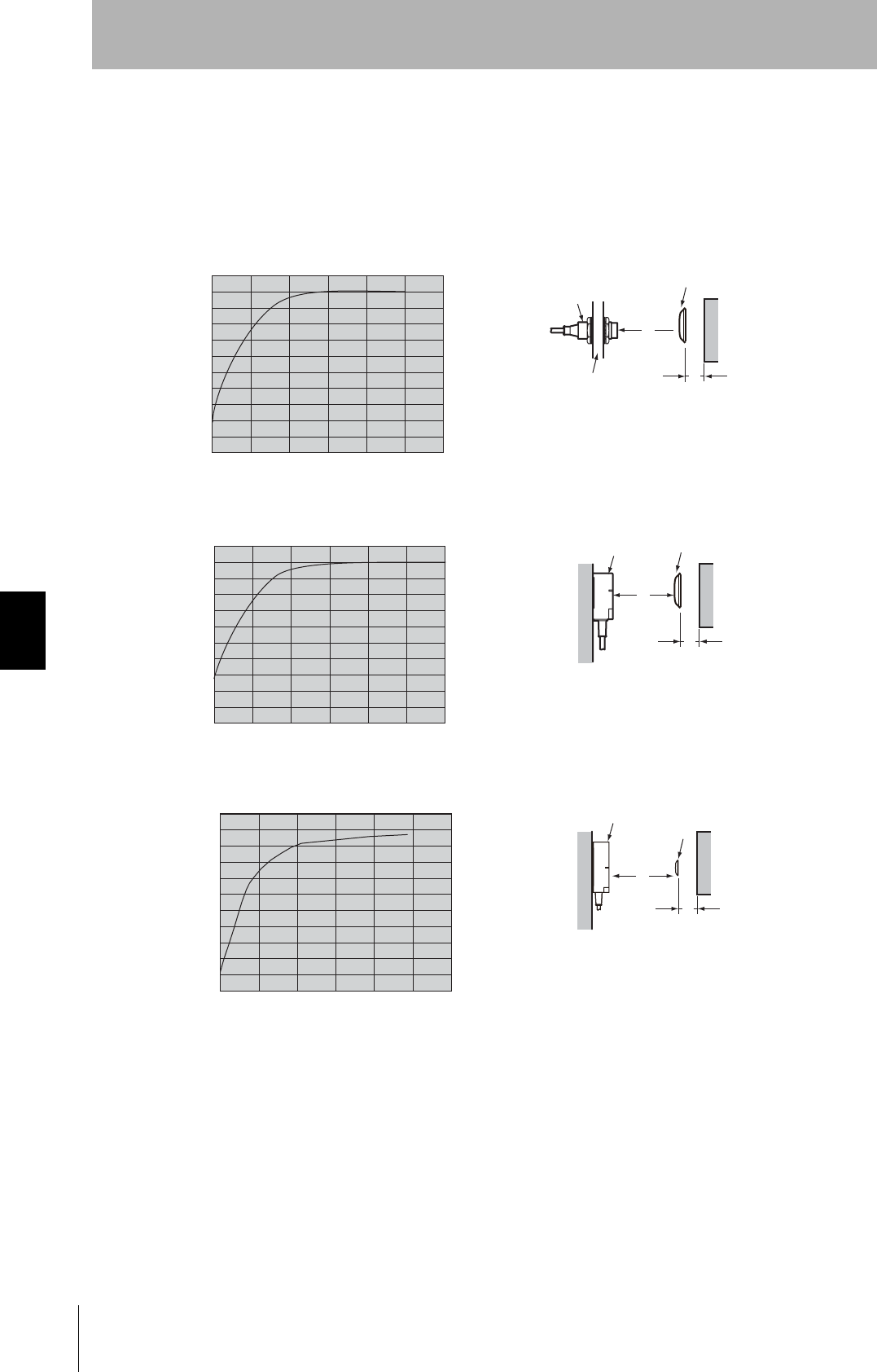
108
Section 6 Reference Data
RFID System
User's Manual
Section 6
Appendices
V680-D1KP66T-SP
The V680-D1KP66T-SP communications distance is reduced if there is any metal material behind the
Tag. If the Tag is mounted on metal, insert a non-metal spacer (such as plastic or resin).
The relationship between the distance from the Tag to the metal surface and the communications
distance is shown below.
● V680-HS52 and V680-D1KP66T-SP
● V680-HS63 and V680-D1KP66T-SP
● V680-HS65 and V680-D1KP66T-SP
Distance to metal (x)
10
20
30
40
50
60
70
80
90
100
(%)
The communications distance
without metal is 100%
010203040 (mm)
50
Antenna
ID Tag
Metal X
Metal on back
Communica-
tions
distance
Y
Distance to metal (x)
10
20
30
40
50
60
70
80
90
100
(%)
The communications distance
without metal is 100%
0 10 20 30 40 (mm)50
Antenna ID Tag
Metal
X
Metal on back
Communica-
tions
distance
Y
Distance to metal (x)
10
20
30
40
50
60
70
80
90
100
(%)
The communications distance
without metal is 100%
0 10 20 30 40 (mm)50
Antenna
ID Tag
Metal
X
Metal on back
Communica-
tions
distance
Y
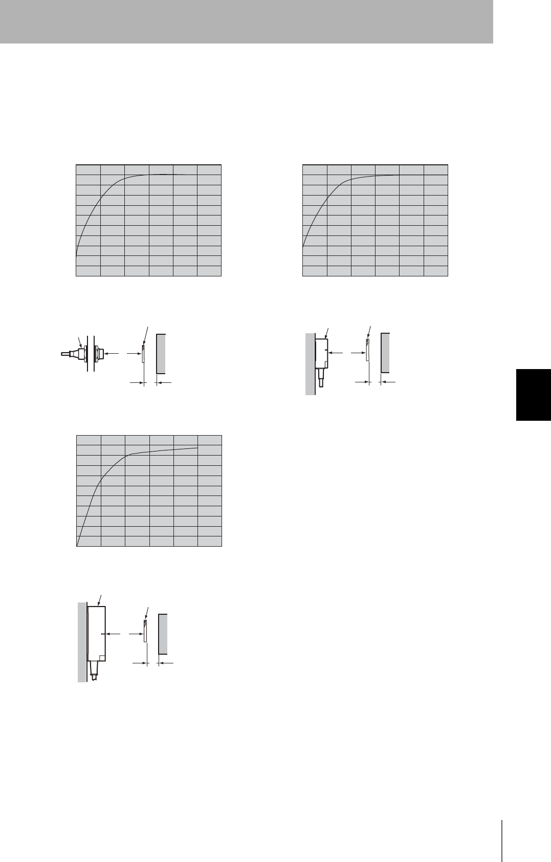
RFID System
User's Manual
109
Section 6 Reference Data
Section 6
Appendices
V680-D2KF67
Effect of Metal behind Tags (Reference)
The V680-D2KF67 communications distance is reduced if there is any metal material behind the Tag.
● V680-HS52 and V680-D2KF67 ● V680-HS63 and V680-D2KF67
● V680-HS65 and V680-D2KF67
Distance to metal (x)
10
20
30
40
50
60
70
80
90
100
(%)
The communications distance
without metal is 100%
010203040 (mm)
50
Distance to metal (x)
10
20
30
40
50
60
70
80
90
100
(%)
The communications distance
without metal is 100%
0 10 20 30 40 (mm)50
Antenna
ID Tag
X
Metal on back
Communica-
tions
distance
Y
X
Y
Antenna ID Tag
Metal Metal on back
Communica-
tions
distance
Distance to metal (x)
10
20
30
40
50
60
70
80
90
100
(%)
The communications distance
without metal is 100%
010203040 (mm)
50
X
Y
Antenna
ID Tag
Metal Metal on back
Communica-
tions
distance
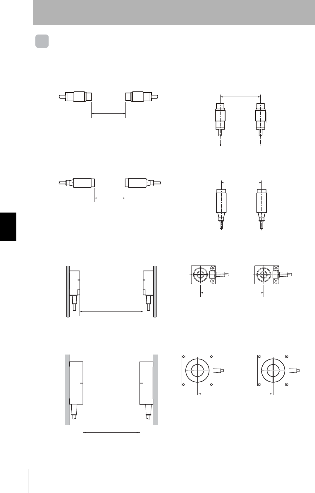
110
Section 6 Reference Data
RFID System
User's Manual
Section 6
Appendices
Mutual Interference between Antennas (Reference)
To prevent malfunctioning due to mutual interference when using more than one Antenna, leave
sufficient space between them as shown in the following diagrams.
V680-HS51
V680-HS52
V680-HS63
V680-HS65
•Installing the Antennas Facing Each Other •Installing the Antennas in Parallel
•Installing the Antennas Facing Each Other •Installing the Antennas in Parallel
•Installing the Antennas Facing Each Other •Installing the Antennas in Parallel
•Installing the Antennas Facing Each Other •Installing the Antennas in Parallel
80 mm min.
80 mm min.
80 mm min.
120 mm min.
100 mm min.
430 mm min.
270 mm min.
700 mm min.
400 mm min.
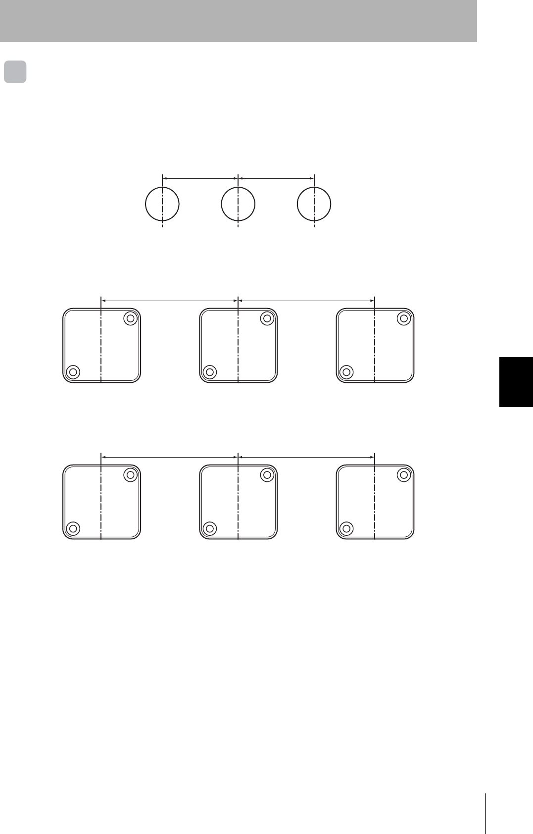
RFID System
User's Manual
111
Section 6 Reference Data
Section 6
Appendices
Mutual Interference with ID Tags (Reference)
To prevent malfunctioning due to mutual interference when using more than one Tag, leave sufficient
space between them as shown in the following diagram.
V680-D1KP52MT
V680-D1KP66T
V680-D1KP66MT
25 mm min. 25 mm min.
100 mm min. 100 mm min.
100 mm min. 100 mm min.
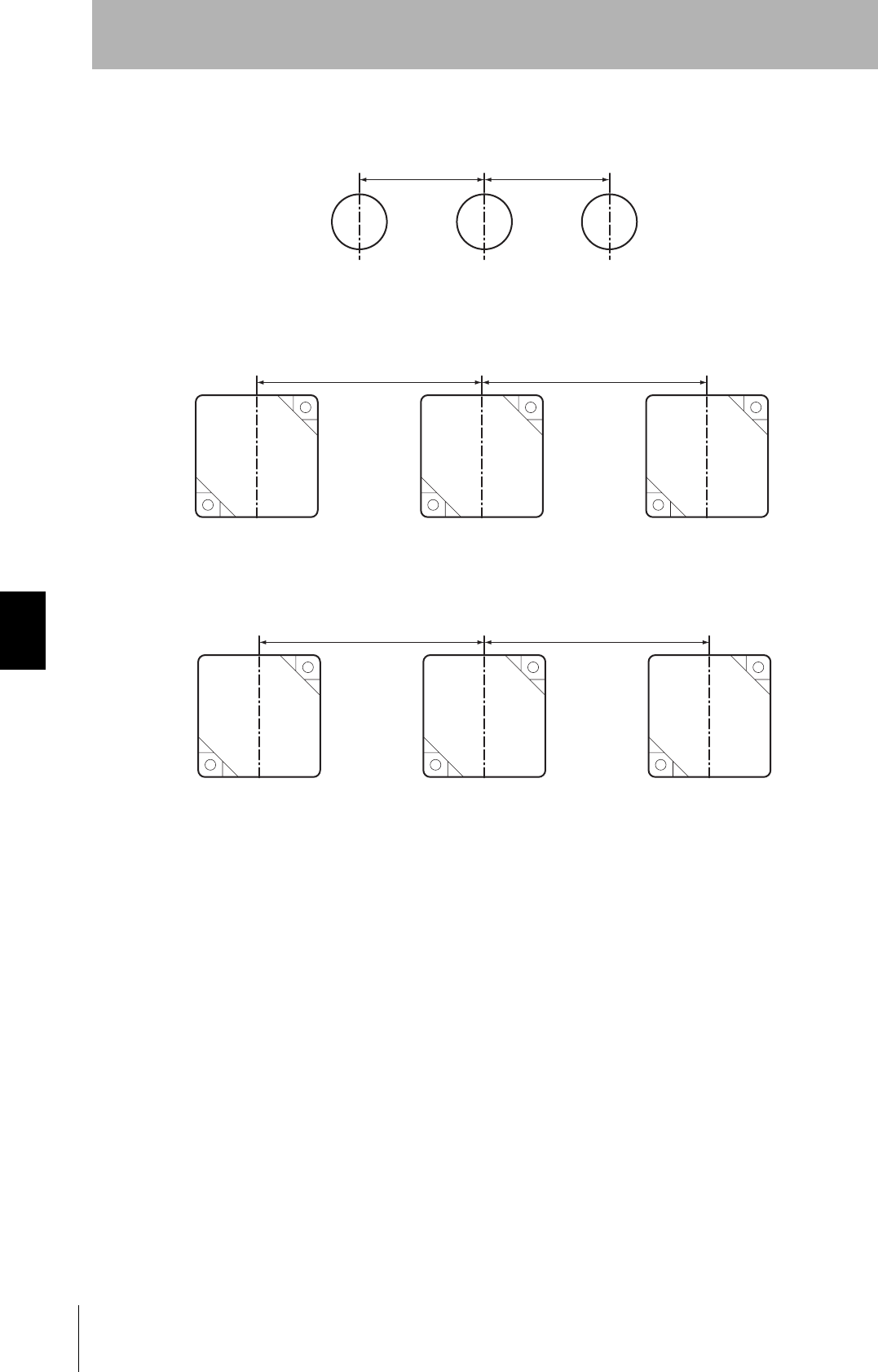
112
Section 6 Reference Data
RFID System
User's Manual
Section 6
Appendices
V680-D2KF52M
When V680-HS51, V680-HS52, and V680-HS63 Are Used
V680-D2KF67
When V680-HS52, V680-HS63, and V680-HS65 Are Used
V680-D2KF67M
When V680-HS52, V680-HS63, and V680-HS65 Are Used
25 mm min. 25 mm min.
200 mm min. 200 mm min.
120 mm min. 120 mm min.
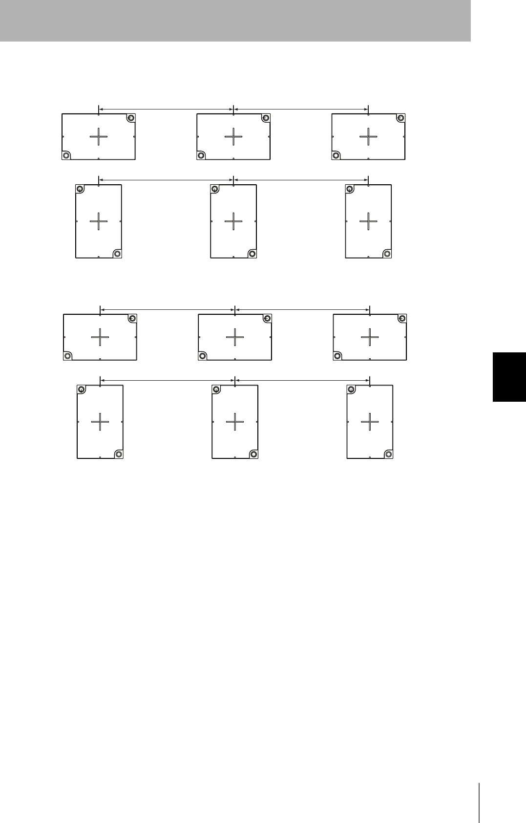
RFID System
User's Manual
113
Section 6 Reference Data
Section 6
Appendices
V680-D8KF68/-D32KF68
When V680-HS63 Is Used
When V680-HS65 Is Used
120 mm min. 120 mm min.
120 mm min. 120 mm min.
150 mm min. 150 mm min.
150 mm min. 150 mm min.
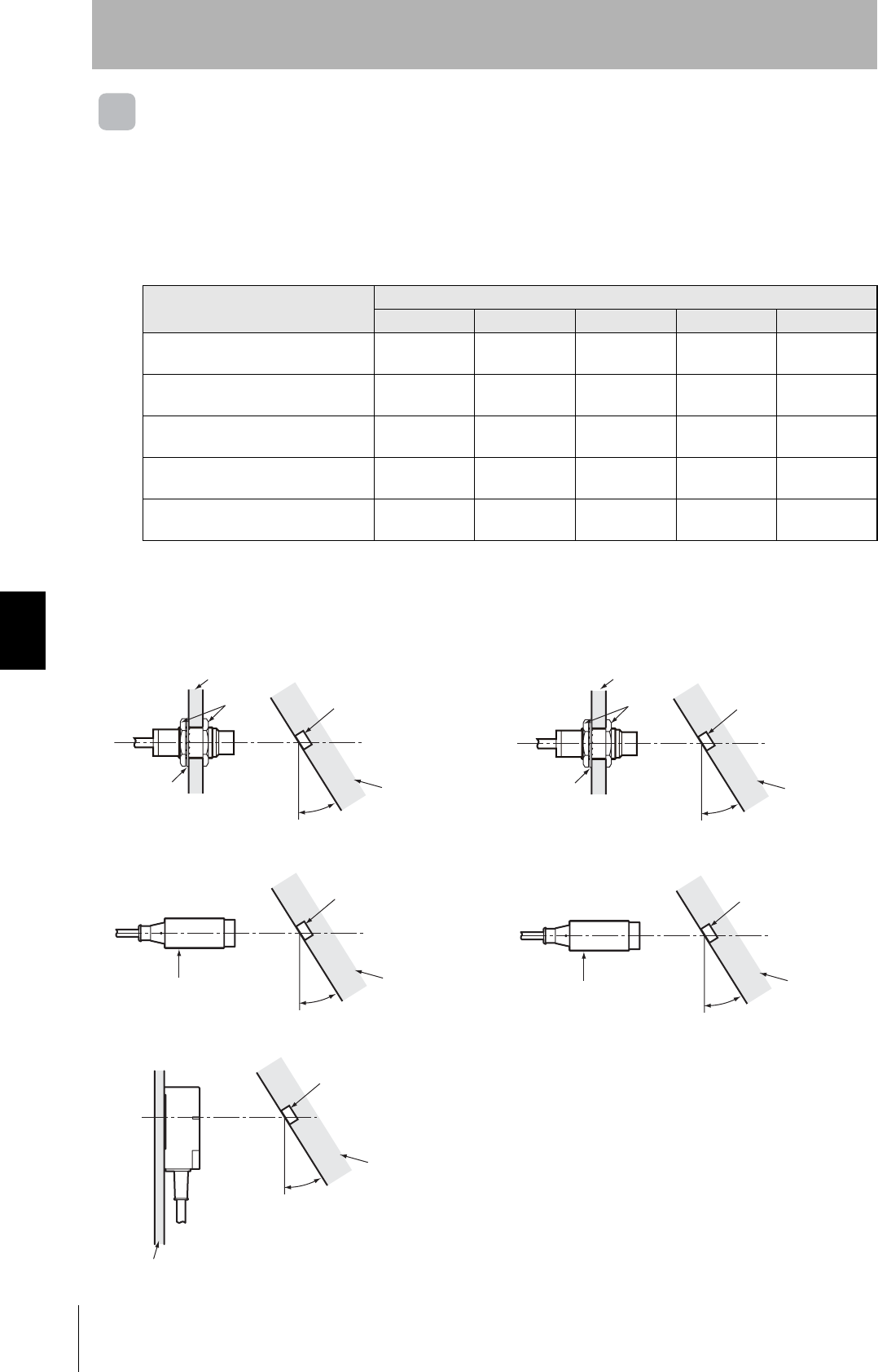
114
Section 6 Reference Data
RFID System
User's Manual
Section 6
Appendices
Influence of Tag Angle (Reference)
Install Antennas and Tags as close to parallel to each other as possible.
Communications are possible even when an Antenna and a Tag are mounted at an angle, but the
communications distance will be shortened. The relation between the angle and the communications
distance is shown below.
Percentage of Change in Communications Distance for 680-D1KP52MT Angle
Measurement Conditions
Tag angle (θ°)
010 20 30 40
V680-HS51 and V680-D1KP52MT 0% −1% −5% −10% −15%
V680-HS51 and V680-D1KP52MT
(Metal on back: Steel) 0% 0% 0% −4% −28%
V680-HS52 and V680-D1KP52MT 0% 0% 0% −2% −6%
V680-HS52 and V680-D1KP52MT
(Metal on back: Steel) 0% −6% −13% −25% ---
V680-HS63 and V680-D1KP52MT 0% −2% −5% −9% −14%
---: Measurement is not possible because Antenna and Tag would strike each other.
z V680-HS51 and V680-D1KP52MT z V680-HS51 and V680-D1KP52MT
(Metal on back: Steel)
z V680-HS52 and V680-D1KP52MT z V680-HS52 and V680-D1KP52MT
(Metal on back: Steel)
z V680-HS63 and V680-D1KP52MT
Tag
Non-metallic
material
Antenna
Steel
Nut
Toothed
washers θ
Tag
Non-metallic
material
Antenna
Steel
Nut
Toothed
washers θ
Tag
Non-metallic
material
Antenna θ
Tag
Steel
Antenna θ
Tag
Non-metallic
material
Antenna
θ

RFID System
User's Manual
115
Section 6 Reference Data
Section 6
Appendices
Reduction in Communications Distance for V680-D1KP66T Angle
Measurement Conditions
Tag angle (θ°)
010 20 30 40
V680-HS52 and V680-D1KP66T 0% −1% −2% −4% −7%
V680-HS63 and V680-D1KP66T 0% −2% −3% −5% −9%
V680-HS65 and V680-D1KP66T 0% −1% −3% −6% −11%
z V680-HS52 and V680-D1KP66T z V680-HS63 and V680-D1KP66T
z V680-HS65 and V680-D1KP66T
Antenna Tag
θ
Antenna
Tag
θ
Non-metallic
material
Antenna
Tag
θ
Metallic
material

116
Section 6 Reference Data
RFID System
User's Manual
Section 6
Appendices
Reduction in Communications Distance for V680-D1KP66MT Angle
Measurement Conditions
Tag angle (θ°)
010 20 30 40
V680-HS52 and V680-D1KP66MT
(Metal on back: Steel) 0% −1% −2% −5% −9%
V680-HS63 and V680-D1KP66MT
(Metal on back: Steel) 0% −1% −4% −7% −13%
V680-HS65 and V680-D1KP66MT
(Metal on back: Steel) 0% −1% −6% −15% ---
---: Measurement is not possible because Antenna and Tag would strike each other.
z V680-HS52 and V680-D1KP66MT
(Metal on back: Steel)
z V680-HS63 and V680-D1KP66MT
(Metal on back: Steel)
z V680-HS65 and V680-D1KP66MT
(Metal on back: Steel)
Antenna Tag
θ
Antenna
Tag
θ
Non-metallic
material
Antenna
Tag
θ
Metallic
material
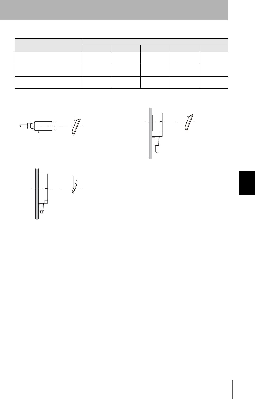
RFID System
User's Manual
117
Section 6 Reference Data
Section 6
Appendices
Reduction in Communications Distance for V680-D1KP66T-SP Angle
Measurement Conditions
Tag angle (θ°)
010 20 30 40
V680-HS52 and V680-D1KP66T 0% −1% −2% −4% −7%
V680-HS63 and V680-D1KP66T 0% −2% −3% −5% −9%
V680-HS65 and V680-D1KP66T 0% −1% −3% −6% −11%
z V680-HS52 and V680-D1KP66T z V680-HS63 and V680-D1KP66T
z V680-HS65 and V680-D1KP66T
Antenna Tag
θ
Antenna
Tag
θ
Metallic
material
Antenna
Tag
θ
Metallic
material
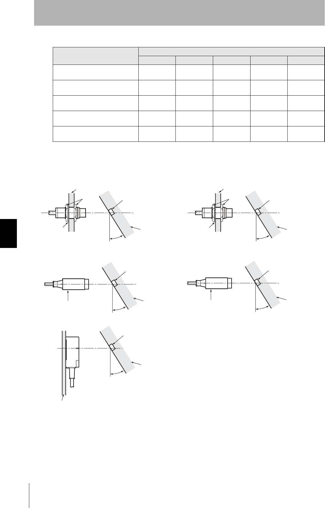
118
Section 6 Reference Data
RFID System
User's Manual
Section 6
Appendices
Reduction in Communications Distance for V680-D2KF52M Angle
Measurement Conditions
Tag angle (θ°)
010 20 30 40
V680-HS51 and V680-D2KF52M 0% −2% −6% -−−22%
V680-HS51 and V680-D2KF52M
(Metal on back: Steel) 0% 0% 0% −7% −30%
V680-HS52 and V680-D2KF52M 0% 0% 0% −2% −5%
V680-HS52 and V680-D2KF52M
(Metal on back: Steel) 0% −2% −7% --- ---
V680-HS63 and V680-D2KF52M 0% 0% −1% −4% −9%
---: Measurement is not possible because Antenna and Tag would strike each other.
z V680-HS51 and V680-D2KF52M z V680-HS51 and V680-D2KF52M
(Metal on back: Steel)
z V680-HS52 and V680-D2KF52M z V680-HS52 and V680-D2KF52M
(Metal on back: Steel)
z V680-HS63 and V680-D2KF52M
Tag
Non-metallic
material
Antenna
Steel
Nut
Toothed
washers θ
Tag
Non-metallic
material
Antenna
Steel
Nut
Toothed
washers θ
Tag
Non-metallic
material
Antenna θ
Tag
Steel
Antenna θ
Tag
Non-metallic
material
θ

RFID System
User's Manual
119
Section 6 Reference Data
Section 6
Appendices
Reduction in Communications Distance for V680-D2KF67 Angle
Measurement Conditions
Tag angle (θ°)
010 20 30 40
V680-HS52 and V680-D2KF67 0% 0% 0% −1% −2%
V680-HS63 and V680-D2KF67 0% −1% −2% −3% −6%
V680-HS65 and V680-D2KF67 0% −1% −3% −7% −11%
z V680-HS52 and V680-D2KF67 z V680-HS63 and V680-D2KF67
z V680-HS65 and V680-D2KF67
Tag
Antenna
θ
Tag
Non-metallic
material
Antenna
θ
Tag
Metallic
material
Antenna
θ
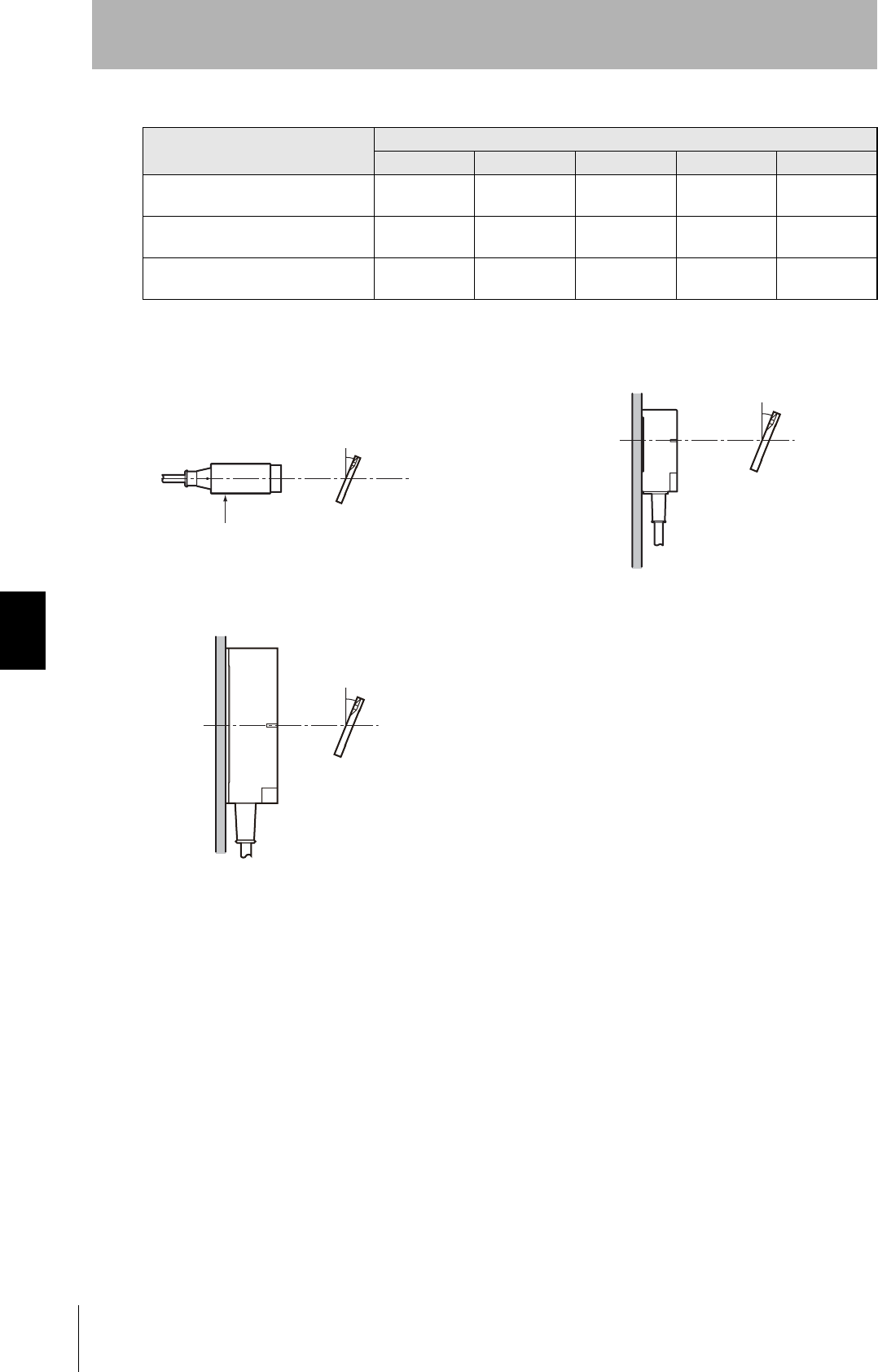
120
Section 6 Reference Data
RFID System
User's Manual
Section 6
Appendices
Reduction in Communications Distance for V680-D2KF67M Angle
Measurement Conditions
Tag angle (θ°)
010 20 30 40
V680-HS52 and V680-D2KF67M
(Metal on back: Steel) 0% −1% −2% −4% −6%
V680-HS63 and V680-D2KF67M
(Metal on back: Steel) 0% −2% −5% −8% −14%
V680-HS65 and V680-D2KF67M
(Metal on back: Steel) 0% −2% −7% −16% −31%
z V680-HS52 and V680-D2KF67M
(Metal on back: Steel)
z V680-HS63 and V680-D2KF67M
(Metal on back: Steel)
z V680-HS65 and V680-D2KF67M
(Metal on back: Steel)
Tag
Antenna
θ
Tag
Non-metallic
material
Antenna
θ
Tag
Metallic
material
Antenna
θ
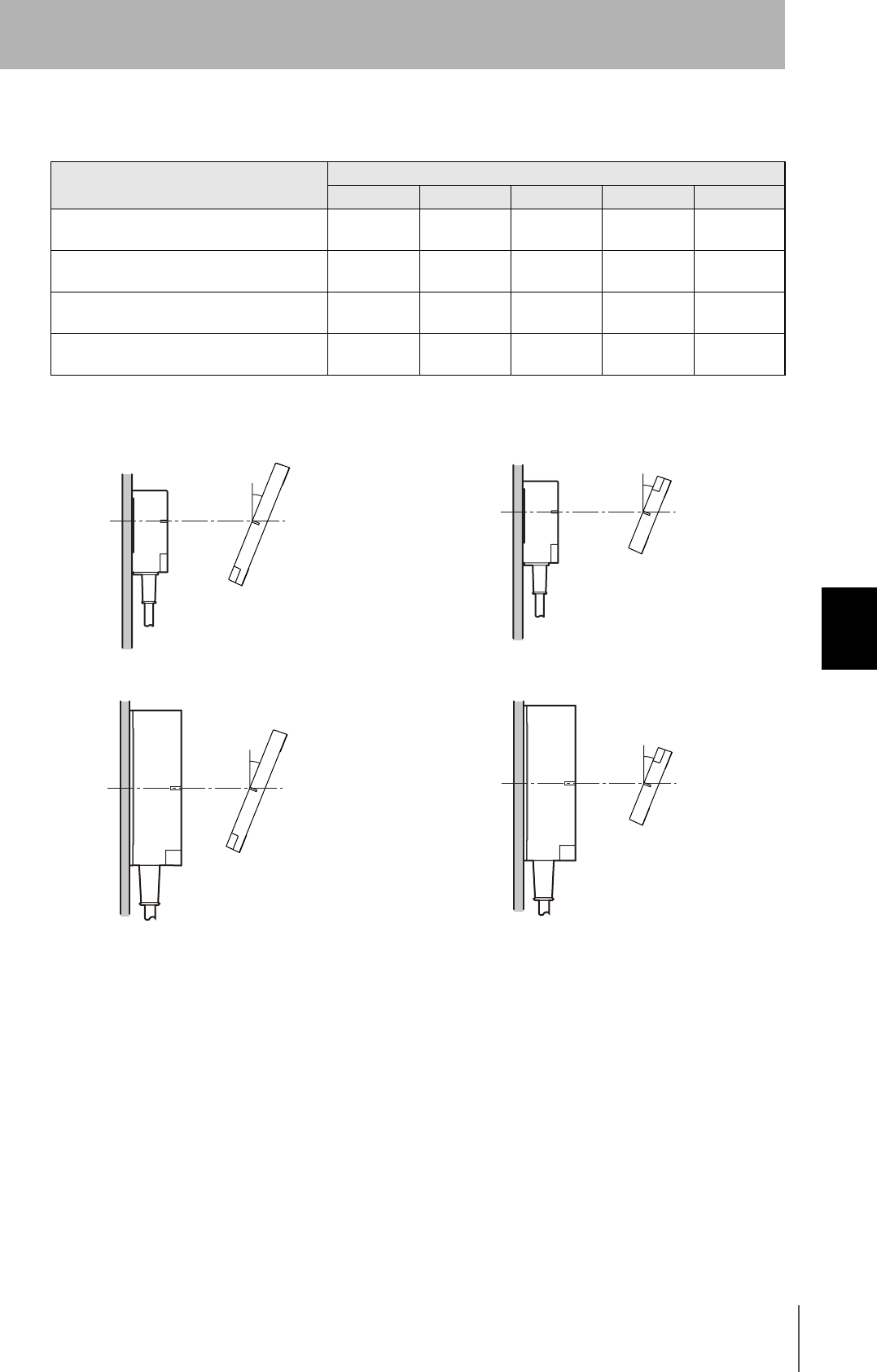
RFID System
User's Manual
121
Section 6 Reference Data
Section 6
Appendices
Reduction in Communications Distance for V680-D8KF68/-D32KF68
Angle
Measurement Conditions
Tag angle (θ°)
010 20 30 40
V680-HS63 and V680-D8KF68/-D32KF68
(Horizontal-facing ID Tag) 0% 0% 0% 0% 0%
V680-HS63 and V680-D8KF68/-D32KF68
(Vertical-facing ID Tag) 0% −1% −2% −3% −5%
V680-HS65 and V680-D8KF68/-D32KF68
(Horizontal-facing ID Tag) 0% −1% −2% −4% −6%
V680-HS65 and V680-D8KF68/-D32KF68
(Vertical-facing ID Tag) 0% −1% −3% −6% −10%
z V680-HS63 and V680-D8KF68/-D32KF68
(Horizontal-facing ID Tag)
z V680-HS63 and V680-D8KF68/-D32KF68
(Vertical-facing ID Tag)
z V680-HS65 and V680-D8KF68/-D32KF68
(Horizontal-facing ID Tag)
z V680-HS65 and V680-D8KF68/-D32KF68
(Vertical-facing ID Tag)
Tag
Metallic
material
Antenna
θ
Tag
Metallic
material
Antenna
θ
Tag
Metallic
material
Antenna
θ
Tag
Metallic
material
Antenna
θ
122
Section 6 Reference Data
RFID System
User's Manual
Section 6
Appendices
Multi-vendor Use
Connecting a Non-OMRON Configurator
This section describes how to connect OMRON Slaves to a non-OMRON Master.
Do not perform communications with a bit strobe connection for Slaves that have outputs. DeviceNet
I/O communications have multiple connection types, such as poll and bit strobe, but for DeviceNet
specifications, bit strobe connections are used for inputs only. Following these specifications, OMRON
Master Units communicate with output Slaves by using a poll connection.
Some non-OMRON Masters perform communications with output units by using a bit strobe
connection. Check the specifications before performing connections when connecting with a non-
OMRON Master.
When connecting an OMRON Slave to a non-OMRON Master, it is necessary to install the OMRON
Slave's EDS file in the non-OMRON Configurator, and set the Slave data in the Master. (Some non-
OMRON Masters can be connected with performing this setting.) In addition to enabling connection to
non-OMRON Masters, installing the EDS file in the Configurator also enables setting specific
parameters for each Slave by using the Configurator.
If the EDS file cannot be obtained or the non-OMRON Configurator does not support EDS files, you must directly input
the connection type and the data size.
Refer to the following devices profiles if more detailed DeviceNet specifications for Slaves are required
when registering the scan list.
Device Profiles
General data Applicable DeviceNet
specifications
Volume 1 Edition 3.1
Volume 3 Edition 1.3
Vendor name OMRON Corporation Vendor ID = 47
Device profile name Slave: Generic Profile number = 0
Product catalog number Manual number
Product revision 2.1
Physical
conformance
data
Network power consumption 24 VDC, 40 mA max.
Connector type Open flag
Physical layer insulation Yes
Support indicator Module
Network
MAC ID setting Set with software or rotary switches (software setting numbers 64 to 99)
Default MAC ID 0
Transmission baud rate setting No (baud rate recognized automatically)
Supported transmission baud rates 125, 250, or 500 kbps
Communications
data
Predefined Master/Slave
connection set
Group 2 only server
Dynamic connection support
(UCOMM)
No
Explicit message fragmentation
support
Ye s
RFID System
User's Manual
123
Section 6 Reference Data
Section 6
Appendices
Object Implementation
Identity Object (0 × 01)
Message Router Object (0 × 02)
DeviceNet Object (0 × 03)
Object class Attribute Not supported
Service Not supported
Object instance Attribute ID Description GET SET Value (hex)
1 Vender {✕47
2 Product type {✕0
3 Product code {✕208
4 Revision {✕2,1
5 Status (Bits Supported) {✕bit 0 only
6 Serial number {✕per Unit
7 Product name {✕V680-
HAM42*1
8 State ✕✕
Service DeviceNet service Parameter option
05Hex Reset No
0EHex Get_Attribute_Single No
*1 The number of characters to be registered is limited, so “-DRT” is omitted.
Object class Attribute Not supported
Service Not supported
Object instance Attribute Not supported
Service Not supported
Addition of vender-specific
specifications
No
Object class Attribute ID Description GET SET Value (hex)
1 Revision {✕02
Service DeviceNet service Parameter option
0EHex Get_Attribute_Single No
124
Section 6 Reference Data
RFID System
User's Manual
Section 6
Appendices
Assembly Object (0 × 04)
** OUT: Instance 100, IN: Instance 101
Connection Object (0 × 05)
Object instance Attribute ID Description GET SET Value (hex)
1 MAC ID {✕
2 Baud rate {✕
3BOI {✕00
4 Bus off counter {✕
5 Allocation information {✕
6 MAC ID switch changed {✕
7 Baud rate switch changed ✕✕
8 MAC ID switch value {✕
9 Baud rate switch value ✕✕
Service DeviceNet service Parameter option
0EHex No
10Hex No
4BHex No
4CHex No
Object class Attribute Not supported
Service Not supported
Object instance
**
Section Data Maximum number of instances
Instance type Static I/O 1
Attribute Description GET SET Value (hex)
1 Number of Members in
List
{✕
2 Member List {✕
3 Data {✕00
Service DeviceNet service Parameter option
0EHex Get_Attribute_Single No
10Hex Set_Attribute_Single No
Object class Attribute Not supported
Service Not supported
Maximum number of
active connections
1
RFID System
User's Manual
125
Section 6 Reference Data
Section 6
Appendices
Object instance1 Section Data Maximum number of instances
Instance type Explicit Message 1
Production trigger Cyclic
Transport type Server
Transport class 3
Attribute ID Description GET SET Value (hex)
1 State {✕
2 Instance type {✕00
3 Transport class trigger {✕83
4 Produced connection ID {✕---
5 Consumed connection ID {✕---
6 Initial comm
characteristics
{✕21
7 Produced connection size {✕F
8 Consumed connection
size
{✕FE
9 Expected packet rate {✕
12 Watchdog time-out action {✕01
13 Produced connection path
length
{✕0000
14 Produced connection path {✕
15 Consumed connection
length
{✕0000
16 Consumed connection
path length
{✕
17 Production inhibit time {✕0000
Service DeviceNet service Parameter option
05ex Reset No
0EHex Get_Attribute_Single No
10Hex Set_Attribute_Single No
126
Section 6 Reference Data
RFID System
User's Manual
Section 6
Appendices
Object instance2 Section Data Maximum number of instances
Instance type Polled I/O 1
Production trigger Cyclic
Transport type Server
Transport class 2
Attribute ID Description GET SET Value (hex)
1 State {✕
2 Instance type {✕00
3 Transport class trigger {✕82
4 Produced connection ID {✕---
5 Consumed connection ID {✕---
6 Initial comm
characteristics
{✕01
7 Produced connection size {✕040
8 Consumed connection
size
{✕0400
9 Expected packet rate {✕
12 Watchdog time-out action {✕00
13 Produced connection path
length
{✕06
14 Produced connection path {✕20,04,24,
64,30,03
15 Consumed connection
length
{✕06
16 Consumed connection
path length
{✕20,04,24,
65,30,03
17 Production inhibit time {✕0000
Service DeviceNet service Parameter option
05ex Reset No
0EHex Get_Attribute_Single No
10Hex Set_Attribute_Single No

RFID System
User's Manual
127
Section 6 Reference Data
Section 6
Appendices
Object instance3 Section Data Maximum number of instances
Instance type Polled I/O 1
Production trigger Cyclic
Transport type Server
Transport class 2
Attribute ID Description GET SET Value (hex)
1 State {✕
2 Instance type {✕01
3 Transport class trigger {✕82
4 Produced connection ID {✕---
5 Consumed connection ID {✕---
6 Initial comm
characteristics
{✕02
7 Produced connection size {✕0400
8 Consumed connection
size
{✕0800
9 Expected packet rate {✕
12 Watchdog time-out action {✕00
13 Produced connection path
length
{✕06
14 Produced connection path {✕20,04,24,
64,30,03
15 Consumed connection
length
{✕0000
16 Consumed connection
path length
{✕---
17 Production inhibit time {✕
Service DeviceNet service Parameter option
05ex Reset No
0EHex Get_Attribute_Single No
10Hex Set_Attribute_Single No

128
Section 6 Chemical Resistance of the Antennas
RFID System
User's Manual
Section 6
Appendices
Chemical Resistance of the Antennas
Applicable Models
ABS resin is used for case material and epoxy resin for filling material. Refer to the following lists and
do not use chemicals that affect ABS and epoxy resin.
Chemicals That Cause Deformations, Cracks, Etc.
Chemicals That May Cause Discoloration, Swelling, Etc.
Chemicals That Do Not Affect ABS Resin or Epoxy Resin
Note: The above results are from tests conducted a room temperature (23°C). Even if the chemicals
do not affect the ABS or epoxy resins at room temperature, they may affect the resins at higher
or lower temperatures. Check the chemicals carefully in advance.
V680-HS51 V680-HS52-W/R V680-HS63-W/R V680-HS65-W/R
ABS resin Epoxy resin
Trichlene, acetone, xylene, toluene, gasoline, creosol,
methylene chloride, phenol, cyclohexane, aqua regia, chromic
acid, sulfuric acid (90% RT), methyl ethyl ketone, aniline,
nitrobenzine, monochlorobenzine, pyridine, nitric acid (60%
RT), formic acid (80% RT)
Aqua regia, chromic acid, sulfuric acid (90% RT), nitric acid
(60% RT), ammonia solution, acetone, methylene chloride,
phenol
ABS resin Epoxy resin
Hydrochloric acid, alcohol, Freon, sodium hydroxide, hydrogen
peroxide, benzine, sulfuric acid (10% RT), nitric acid (10%
RT), phosphoric acid (85% RT), ammonia solution
Sulfuric acid (10% RT), nitric acid (10% RT), hydrochloric acid
(30% RT), acetic acid (50% RT), oxalic acid, calcium
hydroxide, benzine, creosol, alcohol, cyclohexane, toluene,
xylene, benzine, grease
ABS resin Epoxy resin
Ammonia, kerosine, mineral oil, developer, Yushiroken S50,
Chemi-Cool Z, Velocity No. 3, Yushiroken EEE-30Y,
petroleum, grease, acetic acid, oxalic acid, calcium hydroxide,
phosphoric acid (30% RT), hydrochloric acid (10% RT),
potassium hydroxide
Ammonia, hydrochloric acid (10% RT), potassium hydroxide,
petroleum, gasoline, Yushiroken S50, Chemi-Cool Z, Velocity
No. 3, Yushiroken EEE-30Y

RFID System
User's Manual
129
Section 6 Chemical Resistance of Tags
Section 6
Appendices
Chemical Resistance of Tags
Applicable Models
PPS resin is used for case material and epoxy resin for filling material. Refer to the following lists and
do not use chemicals that affect PPS and epoxy resin.
Tags cannot be used in applications with explosion-proof specifications.
Chemicals That Cause Deformations, Cracks, Etc.
Chemicals That May Cause Discoloration, Swelling, Etc.
Chemicals that Do Not Affect PPS Resin or Epoxy Resin
Note: The above results are from tests conducted a room temperature (23°C). Even if the chemicals
do not affect the PPS or epoxy resins at room temperature, they may affect the resins at higher
or lower temperatures. Check the chemicals carefully in advance.
V680-D1KP52 V680-D2KF52M
PPS resin Epoxy resin
Aqua regia Aqua regia, chromic acid, sulfuric acid (90% RT), nitric acid
(60% RT), ammonia solution, acetone, methylene chloride,
phenol
PPS resin Epoxy resin
Nitric acid (60% RT) Sulfuric acid (10% RT), nitric acid (10% RT), hydrochloric acid
(30% RT), acetic acid (50% RT), oxalic acid, calcium
hydroxide, benzine, creosol, alcohol, cyclohexane, toluene,
xylene, benzine, grease
PPS resin Epoxy resin
Hydrochloric acid (37%RT), sulfuric acid (98%RT), nitric acid
(40%RT), Hydrogen fluoride solution (40%RT), chromic acid
(40%RT), hydrogen peroxide (28%RT), sodium hydroxide
solution (60%RT), ammonia solution (28%RT), sodium
chloride (10%RT), sodium carbonate (20%RT), sodium
hypochlorite, phenol solution (5%RT), glacial acetic acid,
acetic acid, oleic acid, Methyl alcohol (95%RT), ethyl alcohol
(95%RT), Ethyl acetate, sebacic acid, diethylhexyl, acetone,
diethyl ether, n-heptane, 2-2-4 trimethylpentane, benzine,
toluene, aniline, mineral oil, gasoline, insulating oil,
dichloroethylene, carbon tetrachloride
Ammonia, hydrochloric acid (10% RT), potassium hydroxide,
petroleum, gasoline, Yushiroken S50, Chemi-Cool Z, Velocity
No. 3, Yushiroken EEE-30Y, methyl ethyl ketone, sodium
hydroxide (10%RT)
130
Section 6 Chemical Resistance of Tags
RFID System
User's Manual
Section 6
Appendices
Applicable Models
The above table shows the extent of changes in PPS resin exposed to each chemical at room temperature and at 90°C.
If actual chemicals, concentrations, and temperatures are different from those shown in the tables, always conduct tests
under the actual conditions in which the Tags are to be used.
V680-D1KP66T/MT
Chemical
At room
temper-
ature
90°CChemical
At room
temper-
ature
90°C
Hydrochloric acid 37% A A Sodium hypochlorite A A
10% A A Phenol solution 5% A A
Sulfuric acid 98% A B Glacial acetic acid A A
50% A A Acetic acid A A
30% A A Oleic acid A A
3% A A Methyl alcohol 95% A A
Nitric acid 60% B C Ethyl alcohol 95% A A
40% A B Ethyl acetate A A
10% A A Sebacic acid diethylhexyl A A
Hydrogen fluoride solution 40% A A Acetone A A
Chromic acid 40% A A Diethyl ether A A
Hydrogen peroxide solution 28% A B n-heptane A A
3% A A 2-2-4 trimethylpentane A A
Sodium hydroxide solution 60% A A Benzene A A
10% A A Toluene A A
1% A A Aniline A A
Ammonia solution 28% A B Mineral oil A A
10% A B Gasoline A A
Sodium chloride 10% A A Insulating oil A A
Sodium carbonate 20% A A Dichloroethylene A A
2% A A Carbon tetrachloride A A
A: Has no adverse effect, B: May cause discoloration, swelling, etc., C: Causes deformation, cracks, etc.

RFID System
User's Manual
131
Section 6 Chemical Resistance of Tags
Section 6
Appendices
Applicable Model
PFA is used for the V680-D1KP66T-SP ID Tag coating.
Refer to the following materials and check the characteristics before using them.
Chemical Resistance of PFA Fluororesin (Reference Material)
PFA: Tetrafluorethylene-Perfluoroalkylvinyletheir copolymer
PFA fluororesin is non-reactive to most chemicals.
It reacts to alkaline metals in the melted state, F2 (fluorine) under high temperature and high pressure,
and some halogen derivatives.
The results testing by immersing the PFA material in commonly used organic and inorganic chemicals
are shown below. This testing involves placing a compression molded test piece (1.3 mm thickness) in
the chemicals at room temperature for one week (168 hours), then removing it to measure the change
in weight, tensile strength, and stretch. If the change in tensile strength is less than 15%, elasticity is
less than 10%, and weight is less than 0.5%, the effect is considered minimal.
When fluids that wet the resin surface, such as trichloroacetic acid, Tri-n-butylamine hydrofluoride,
perchloroethylene, and carbon tetrachloride, are applied at high temperatures, it is likely that the PFA
will increase weight by absorption and lose its tensile strength. Even if chemicals that are solvents are
absorbed, the molecular structure will not change. If the PFA is subject to deformation at high
temperatures, deformation at high pressures, or other physical damage, the absorbed chemicals will
repeatedly expand and contract within the PFA, causing physical defects such as cracks or blistering.
However, these are problems that are likely to occur with any type of plastic.
Inorganic Chemicals
V680-D1KP66T-SP
Chemical Test temperature
(°C)
Residual characteristic (%) Weight gain (%)
Tensile strength Stretch
Concentrated hydrochloric acid 120 98 100 0.0
Concentrated sulfuric acid 120 95 98 0.0
Hydrofluoric acid (60%RT) 23 99 99 0.0
Fuming sulfuric acid 23 95 96 0.0
Aqua regia 120 99 100 0.0
Chromic acid (50% RT) 120 93 97 0.0
Concentrated nitric acid 120 95 98 0.0
Fuming nitric acid 23 99 99 0.0
66 98 100 100 0.0
Caustic soda (50% RT) 120 93 99 0.4
Hydrogen peroxide solution (30% RT) 23 93 95 0.0
Bromine 23 99 100 0.0
Chlorine 120 92 100 0.5
Ferrous chloride (25% RT) 100 93 98 0.0
Zinc chloride (25% RT) 100 96 100 0.0
Sulfuryl chloride 69 83 100 2.7
Chlorosulfonic acid 151 91 100 0.0
Concentrated phosphoric acid 100 93 100 0.0

132
Section 6 Chemical Resistance of Tags
RFID System
User's Manual
Section 6
Appendices
Organic Chemicals
Chemical Test temperature
(°C)
Residual characteristic (%) Weight gain (%)
Tensile strength Stretch
Water-acetic acid 118 95 100 0.4
Acetic anhydride 139 91 99 0.3
Trichloroacetic acid 196 90 100 2.2
Isooctane 99 94 100 0.7
Naphtha 100 91 100 0.5
Mineral oil 180 87 95 0.0
Toluene 110 88 100 0.7
o-Creosol 191 92 96 0.2
Nitrobenzene 210 90 100 0.7
Benzyl alcohol 205 93 99 0.3
Aniline 185 94 100 0.3
n-Butylamine 78 86 97 0.4
Ethylenediamine 117 96 100 0.1
Tetrahydrofuran 66 88 100 0.7
Benzaldehyde 179 90 99 0.5
Cyclohexane 156 92 100 0.4
Methyl ethyl ketone 80 90 100 0.6
Acetophenone 202 90 100 0.6
Dimethylphtalate 200 98 100 0.3
n-Butyl acetate 125 93 100 0.5
Tri-n-butyl phosphate 200 91 100 2.0
Methylene chloride 40 94 100 0.8
Perchloroethylene 121 86 100 2.0
Carbon tetrachloride 77 87 100 2.3
Dimethyl formamide 154 96 100 0.2
Dimethyl sulfoxide 189 95 100 0.1
Dioxane 101 92 100 0.6
Reference: Satokawa Takaomi, Fluoro-resin Handbook, Nikkan Kogyo Shimbun Ltd.

RFID System
User's Manual
133
Section 6 Chemical Resistance of Tags
Section 6
Appendices
Substances Extracted from Tag (Reference)
If chemicals penetrate through PFA into the Tag (V680-D1KP66T) built into the V680-D1KP66T-SP,
ions may be extracted from the Tag.
Results of Ion-exchange Chromatography
A built-in Tag was soaked in hot water (100°C for 16 hours), and extracted ions were analyzed. The
results are shown below.
Extracted Ions (Concentration)
Cl: 0.5 ppm, Na+: 10 ppm, NH4+: 11 ppm, K+: 1.0 ppm
Results of ICP Emission Spectral Analysis
The V680-D1KP66T-SP Tag was soaked in concentrated hydrochloric acid (which can easily penetrate
through PFA) at 80°C for 300 hours, then extracted substances were analyzed.
Extracted Substances (Concentration)
Si: 700 ng/ml, S: 1,000 ng/ml, Ca: 30 ng/ml
The chemical resistance and extracted substances presented here should be used for reference only. The rates of
change in Tag characteristics and the amounts of substances extracted will vary with temperatures and chemical
concentrations. Before using Tags under actual production environment, always conduct tests to check for any
problems.

134
Section 6 Chemical Resistance of Tags
RFID System
User's Manual
Section 6
Appendices
Applicable Models
Chemicals that affect Tags are shown below.
ABS resin is used for case material and epoxy resin for filling material. Refer to the following lists and
do not use chemicals that affect ABS and epoxy resin.
Tags cannot be used in applications with explosion-proof specifications.
Chemicals That Cause Deformations, Cracks, Etc.
Chemicals That May Cause Discoloration, Swelling, Etc.
Chemicals That Do Not Affect ABS Resin or Epoxy Resin
Note: The above results are from tests conducted a room temperature (23°C). Even if the chemicals
do not affect the ABS or epoxy resins at room temperature, they may affect the resins at higher
or lower temperatures. Check the chemicals carefully in advance.
V680-D2KF67/67M
ABS resin Epoxy resin
Trichlene, acetone, xylene, toluene, gasoline, creosol,
methylene chloride, phenol, cyclohexane, aqua regia, chromic
acid, sulfuric acid (90% RT), methyl ethyl ketone, aniline,
nitrobenzine, monochlorobenzine, pyridine, nitric acid (60%
RT), formic acid (80% RT)
Aqua regia, chromic acid, sulfuric acid (90% RT), nitric acid
(60% RT), ammonia solution, acetone, methylene chloride,
phenol
ABS resin Epoxy resin
Hydrochloric acid, alcohol, Freon, sodium hydroxide, hydrogen
peroxide, benzine, sulfuric acid (10% RT), nitric acid (10%
RT), phosphoric acid (85% RT), ammonia solution
Sulfuric acid (10% RT), nitric acid (10% RT), hydrochloric acid
(30% RT), acetic acid (50% RT), oxalic acid, calcium
hydroxide, benzine, creosol, alcohol, cyclohexane, toluene,
xylene, benzine, grease
ABS resin Epoxy resin
Ammonia, kerosine, mineral oil, developer, Yushiroken S50,
Chemi-Cool Z, Velocity No. 3, Yushiroken EEE-30Y,
petroleum, grease, acetic acid, oxalic acid, calcium hydroxide,
phosphoric acid (30% RT), hydrochloric acid (10% RT),
potassium hydroxide
Ammonia, hydrochloric acid (10% RT), potassium hydroxide,
petroleum, gasoline, Yushiroken S50, Chemi-Cool Z, Velocity
No. 3, Yushiroken EEE-30Y

RFID System
User's Manual
135
Section 6 Chemical Resistance of Tags
Section 6
Appendices
Applicable Models
Chemicals that affect Tags are shown below.
Polybutylene terephthalate (PBT) resin is used for case material and epoxy resin for filling material.
Refer to the following lists and do not use chemicals that affect PBT and epoxy resins.
Tags cannot be used in applications with explosion-proof specifications.
Chemicals That Cause Deformations, Cracks, Etc.
Chemicals That May Cause Discoloration, Swelling, Etc.
Chemicals that Do Not Affect PPS Resin or Epoxy Resin
Note: The above results are from tests conducted at room temperature (23°C). Even if the chemicals
do not affect the PPS or epoxy resins at room temperature, they may affect the resins at higher
or lower temperatures. Check the chemicals carefully in advance.
MEMO
V680-D8KF68/D32KF68
PBT resin Epoxy resin
Acetone, trichloroethylene, ethylene dichloride, sodium
hydroxide, and other alkaline substances
Aqua regia, chromic acid, sulfuric acid (90% RT), nitric acid
(60% RT), liquid ammonia, acetone, methylene chloride,
phenol
PBT resin Epoxy resin
Hydrochloric acid (10% RT), acetic acid (5% RT), benzene Sulfuric acid (10% RT), nitric acid (10% RT), concentrated
hydrochloric acid, acetic acid (50% RT), nitric acid, calcium
hydroxide, benzene, cresol, alcohol, microhexanon, toluene,
xylene, benzene, grease
PBT resin Epoxy resin
Nitric acid (30% RT), concentrated hydrochloric acid, acetic
acid, ethyl acetate (100% RT), potassium permaganate (5%
RH), ethyl acetate, carbon tetrachloride, methanol, ethanol,
gasoline
Ammonia, hydrochloric acid (10% RT), calcium hydroxide,
petroleum, gasoline, Yushiroken S50, Chemi-cool Z, Velocity
No. 3, Yushiroken EEE-30Y, methyl ethyl ketone, sodium
hydroxide
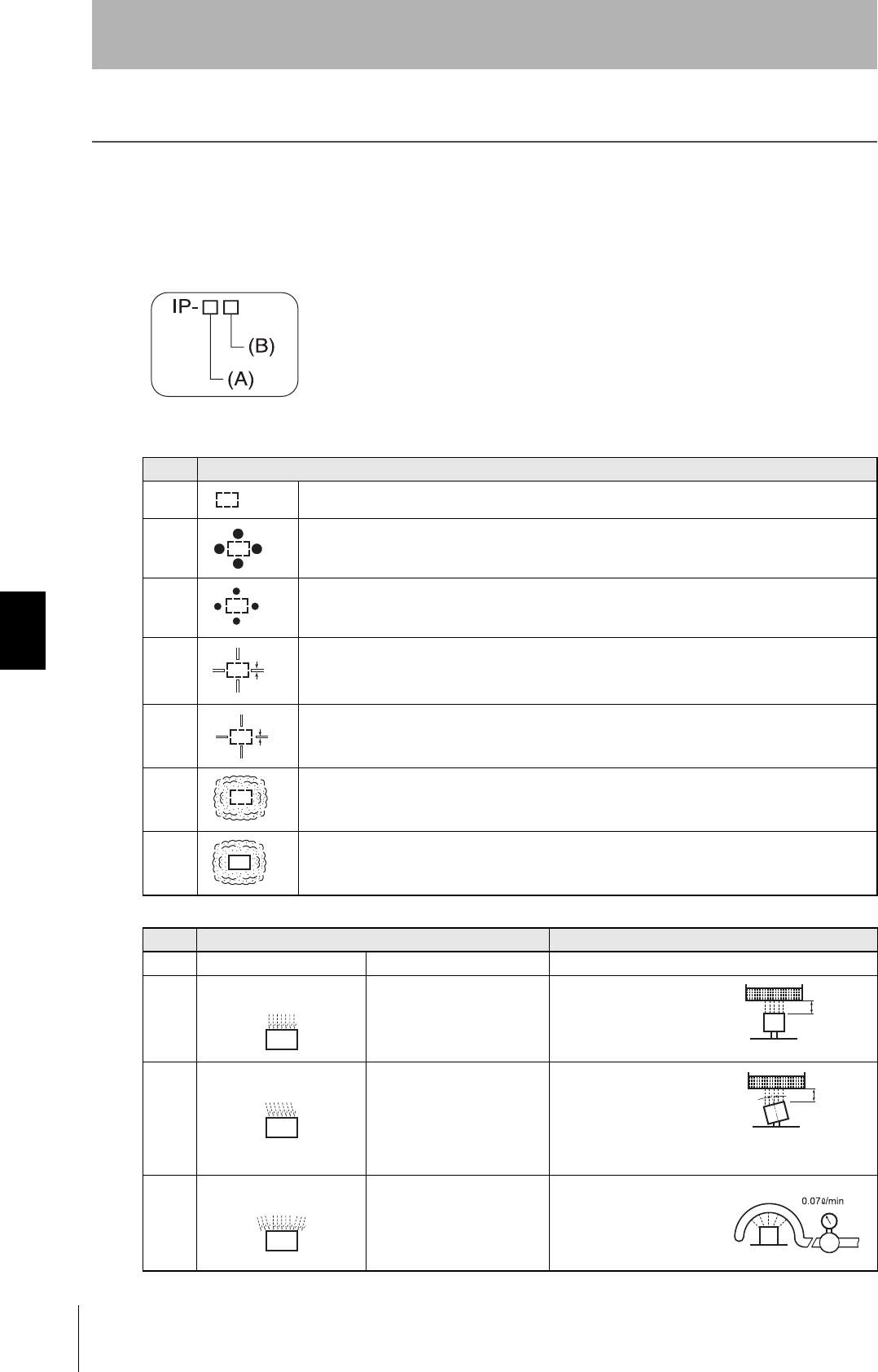
136
Section 6 Degree of Protection
RFID System
User's Manual
Section 6
Appendices
Degree of Protection
Ingress protection degrees (IP-@@) are determined by the following tests. Be sure to check the sealing
capability under the actual operating environment and conditions before actual use.
IEC (International Electrotechnical Commission)
IEC 60529:1989-11
(A) First Digit: Degree of Protection from Solid Materials
(B) Second Digit: Degree of Protection Against Water
Degree Protection
0No protection
1
Protects against penetration of any solid object such as a hand that is 50 mm or more in diameter.
2
Protects against penetration of any solid object, such as a finger, that is 12.5 mm or more in
diameter. Even if finger or other object 12 mm in diameter penetrates, it will not reach a hazardous
part.
3
Protects against penetration of any solid object, such as a wire, that is 2.5 mm or more in diameter.
4
Protects against penetration of any solid object, such as a wire, that is 1 mm or more in diameter.
5
Protects against penetration of dust of a quantity that may cause malfunction or obstruct the safe
operation of the product.
6
Protects against penetration of all dust.
Degree Protection Test method (with pure water)
0 No protection Not protected against water. No test
1 Protection against water
drops
Protects against vertical drops
of water towards the product.
Water is dropped vertically
towards the product from
the test machine for 10
min.
2 Protection against water
drop
Protects against drops of
water approaching at a
maximum angle of 15° to the
left, right, back, and front from
vertical towards the product.
Water is dropped for 2.5
min each (i.e., 10 min in
total) towards the product
inclined 15° to the left,
right, back, and front from
the test machine.
3 Protection against
sprinkled water
Protects against sprinkled
water approaching at a
maximum angle of 60° from
vertical towards the product.
Water is sprinkled for 10
min at a maximum angle of
60° to the left and right
from vertical from the test
machine.
50 mm di
a
12.5 mm d
i
2.5 mm
1 mm
200 mm
200 mm
15°
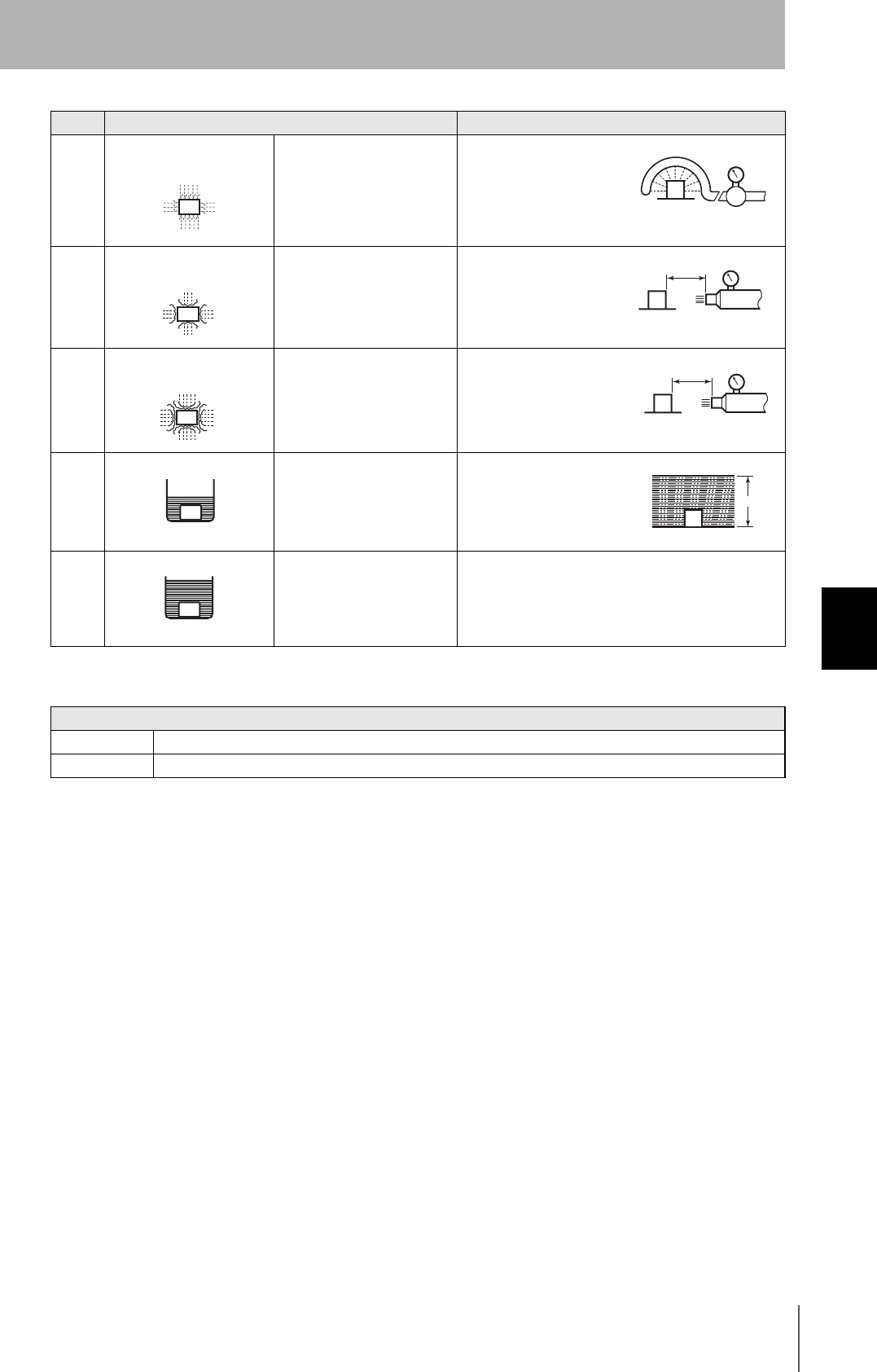
RFID System
User's Manual
137
Section 6 Degree of Protection
Section 6
Appendices
Oil resistance (OMRON in-house standard)
4 Protection against water
spray
Protects against water spray
approaching at any angle
towards the product.
Water is sprayed at any
angle towards the product
for 10 min from the test
machine.
5 Protection against water jet
spray
Protects against water jet
spray approaching at any
angle towards the product.
Water is jet sprayed at any
angle towards the product
for 1 min per square meter
for at least 3 min in total
from the test machine.
6 Protection against high
pressure water jet spray
Protects against high-
pressure water jet spray
approaching at any angle
towards the product.
Water is jet sprayed at any
angle towards the product
for 1 min per square meter
for at least 3 min in total
from the test machine.
7 Protection underwater Resists the penetration of
water when the product is
placed underwater at
specified pressure for a
specified time.
The product is placed 1 m
deep in water (if the
product is 850 mm max. in
height) for 30 min.
8 Protection underwater Can be used continuously
underwater.
The test method is
determined by the
manufacturer and user.
Protection
Oil-resistant No adverse affect from oil drops or oil spray approaching from any direction.
Oil-proof Protects against penetration of oil drops or oil spray approaching from any direction.
Note: This OMRON in-house standard confirms resistance to cutting and other oils. It is equivalent to the former JEM standard.
Degree Protection Test method (with pure water)
0.07 liter/min
2.5 to 3 m 12.5 liter/min
Discharging nozzle: 6.3 dia.
2.5 to 3 m 100 liter/min
Discharging nozzle: 12.5 dia.
1 m

138
Section 6 Degree of Protection
RFID System
User's Manual
Section 6
Appendices
MEMO

RFID System
User's Manual
139
Section 6 Degree of Protection
Section 6
Appendices

140 RFID System
User's Manual
Revision History
A manual revision code appears as a suffix to the catalog number at the bottom of the front and rear pages.
Revision code Date Revised contents
01 January 2008 Original production
Cat. No.: NTLP-E1-01
Revision code

Authorized Distributor:
OMRON Corporation
Industrial Automation Company
Sensing Devices Division H.Q.
Industrial Sensors Division
Shiokoji Horikawa, Shimogyo-ku,
Kyoto, 600-8530 Japan
Tel: (81)75-344-7022/Fax: (81)75-344-7107
Regional Headquarters
OMRON EUROPE B.V.
Sensor Business Unit
Carl-Benz-Str. 4, D-71154 Nufringen,
Germany
Tel: (49) 7032-811-0/Fax: (49) 7032-811-199
OMRON ELECTRONICS LLC
One Commerce Drive Schaumburg,
IL 60173-5302 U.S.A.
Tel: (1) 847-843-7900/Fax: (1) 847-843-7787
OMRON ASIA PACIFIC PTE. LTD.
No. 438A Alexandra Road # 05-05/08 (Lobby 2),
Alexandra Technopark, Singapore 119967
Tel: (65) 6835-3011/Fax: (65) 6835-2711
OMRON (CHINA) CO., LTD.
Room 2211, Bank of China Tower,
200 Yin Cheng Zhong Road,
Pu Dong New Area, Shanghai, 200120, China
Tel: (86) 21-5037-2222/Fax: (86) 21-5037-2200
Cat. No. NTLP
In the interest of product improvement, specifications are
subject to change without notice.
Printed in Japan