Omron 6CYSIDV6800208 ReaderWriter/ RFID System User Manual Z279 E1 01
Omron Corporation ReaderWriter/ RFID System Z279 E1 01
Omron >
Contents
User Manual 2

Section 7 Chemical Resistance
107
RFID System
User's Manual
Section 7
Chemical Resistance
Specification 108
Characteristic data 128
Reference Data 145
108
Section 7 Specification
RFID System
User's Manual
Section 7
Chemical Resistance
Specification
ID Sensor
General Specifications
Interface Cable
V680-HAM91/-HAM81
Characteristic V680-HAM91/-HAM81
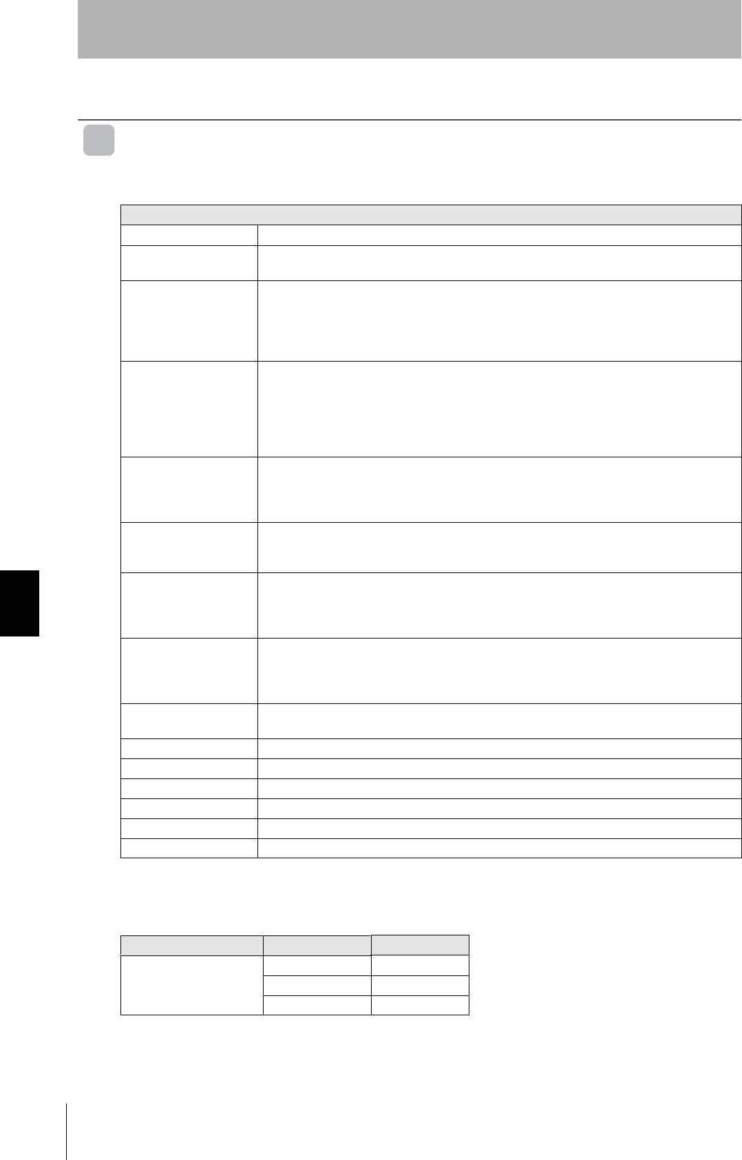
Supply voltage 24 VDC (-15% to 10%) ripple (p-p) 10% is contained.
Power consumption Up to 3.5 W (At the power supply voltage 24 V. Current Up to 0.15 A. It doesn’t contain the I/O
electric current.)
Input specification Transistor output
Shortening electric current:3 mA
Turning off voltage DC15Ω to 30 V, Turning on voltage DC0Ω to 5 V
Input Imbedans 8.2 kΩ
Applied voltage DC30 V (Max.)
Output specification V680-HAM91:NPN open collector output
DC30V,20 mA(Max.)
Residual voltage Up to 2 V
V680-HAM81:PNP open collector output
DC30V,20 mA(Max.)
Residual voltage Up to 2 V
Ambient operating
temperature
At operation -10 to +55°C
(No freezing. There is no dew formation.)
At preservation -25 to +65°C
(No freezing. There is no dew formation.)
Ambient operating
humidity
At operation,At preservation 25 to 85%RH
(No freezing. There is no dew formation.
The ambient temperature of 85%RH is 40°C or less.)
Insulation resistans 20MΩ min. (with 500 VDC mega)
Between power supply terminals and ground/casing
Between power supply terminals/other unit terminals and
ground/casing
Withstand voltage 1000 VAC, 50/60 Hz, 1 min
Between power supply terminals and ground/casing
Between power supply terminals/other unit terminals and
ground/casing
Vibration resistanse 10 to 150 Hz, double amplitude: 0.2 mm, Acceleration: 150 m/s2,
with 10 sweep of 8 min each in 3 directions
Shock resistance Mechanical durability: 150 m/s2, 3times each in 6 directions
Dimensions 90 × 30 × 65 mm (excluding protruding parts)
Degree of protection IEC60529Standard IP40 (Panel-mounting)
Material PC/ABS resin
Weight Approx. 130 g
Mounting method DIN DIN rail
V680-A60 2M/5M/10M
Cable length Model
Interface Cable
(Connector: 26 pin)
2m V680-A60 2m
5m V680-A60 5m
10m V680-A60 10m
The extension cable connector is not waterproof. If necessary, place the
connector inside the control box to prevent exposed to water. The
maximum cable length is 10 m.
109
RFID System
User's Manual
Section 7 Specification
Section 7
Chemical Resistance
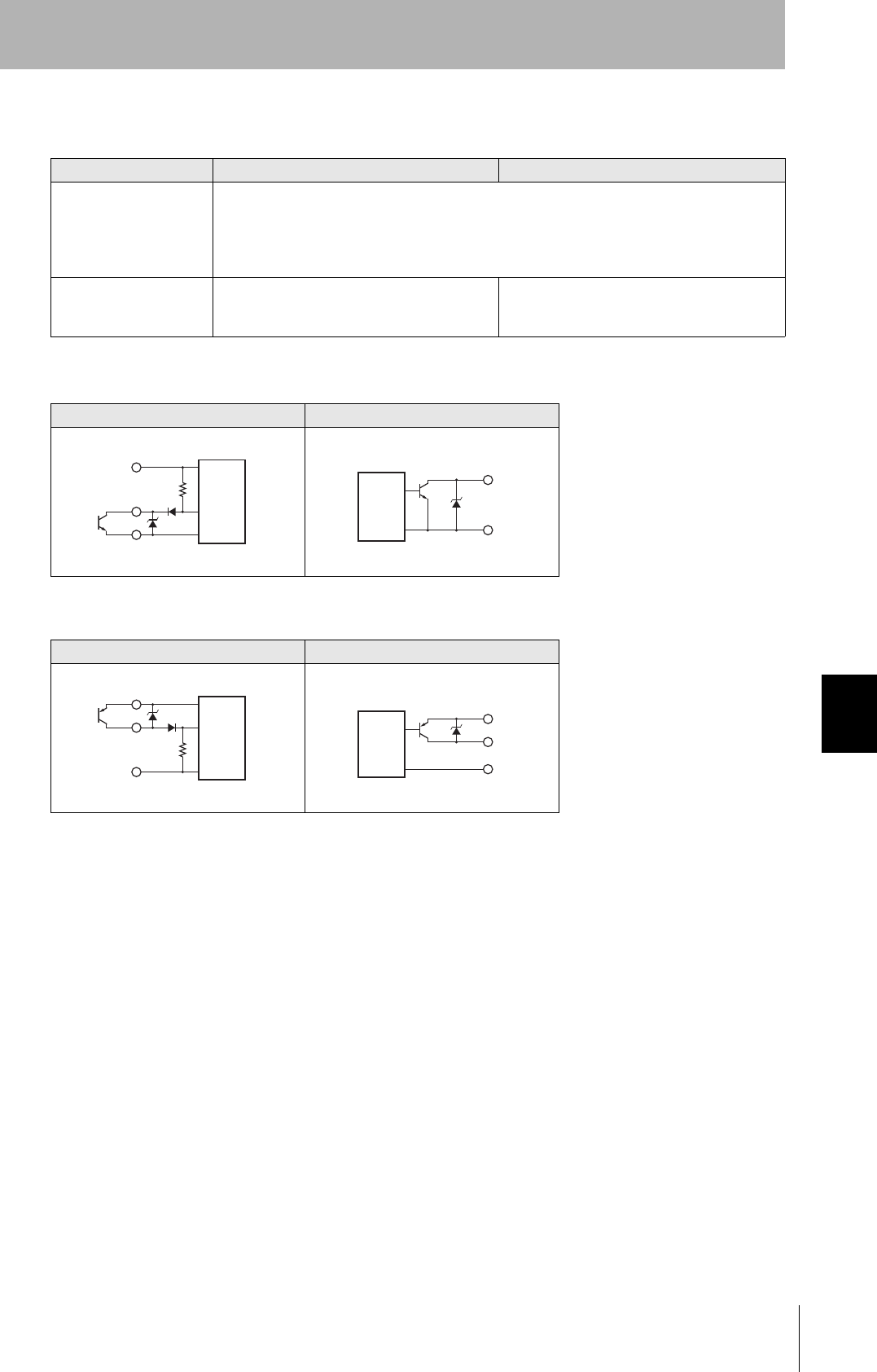
I/O Circuit Diagrams
I/O Circuit Diagrams
Item V680-HAM91 V680-HAM81
入力仕様 Transistor INPUT
Short circuit current : 3mA(TYP)
OFF Voltage : DC15~30V、 ON Voltage : DC0~5V
Input impedance : 8.2kΩ
DC30V(max.)
出力仕様 SINK type :
DC30V、 20mA(max.)
Residual Voltage : below 2V
Source type :
DC30V、 20mA(max.)
Residual Voltage : below 2V
V680-HAM91
Input circuit Output circuit
V680-HAM81
Input circuit Output circuit
24 V
IN
Tr
8.2 kΩ
0 V
Main
circuit
OUT
0V
Main
circuit
+DC(24V)
I
Tr
8.2 kΩ
0V
Main
circuit
+DC(24 V)
0 V
OUT
Main
circuit
110
Section 7 Specification
RFID System
User's Manual
Section 7
Chemical Resistance
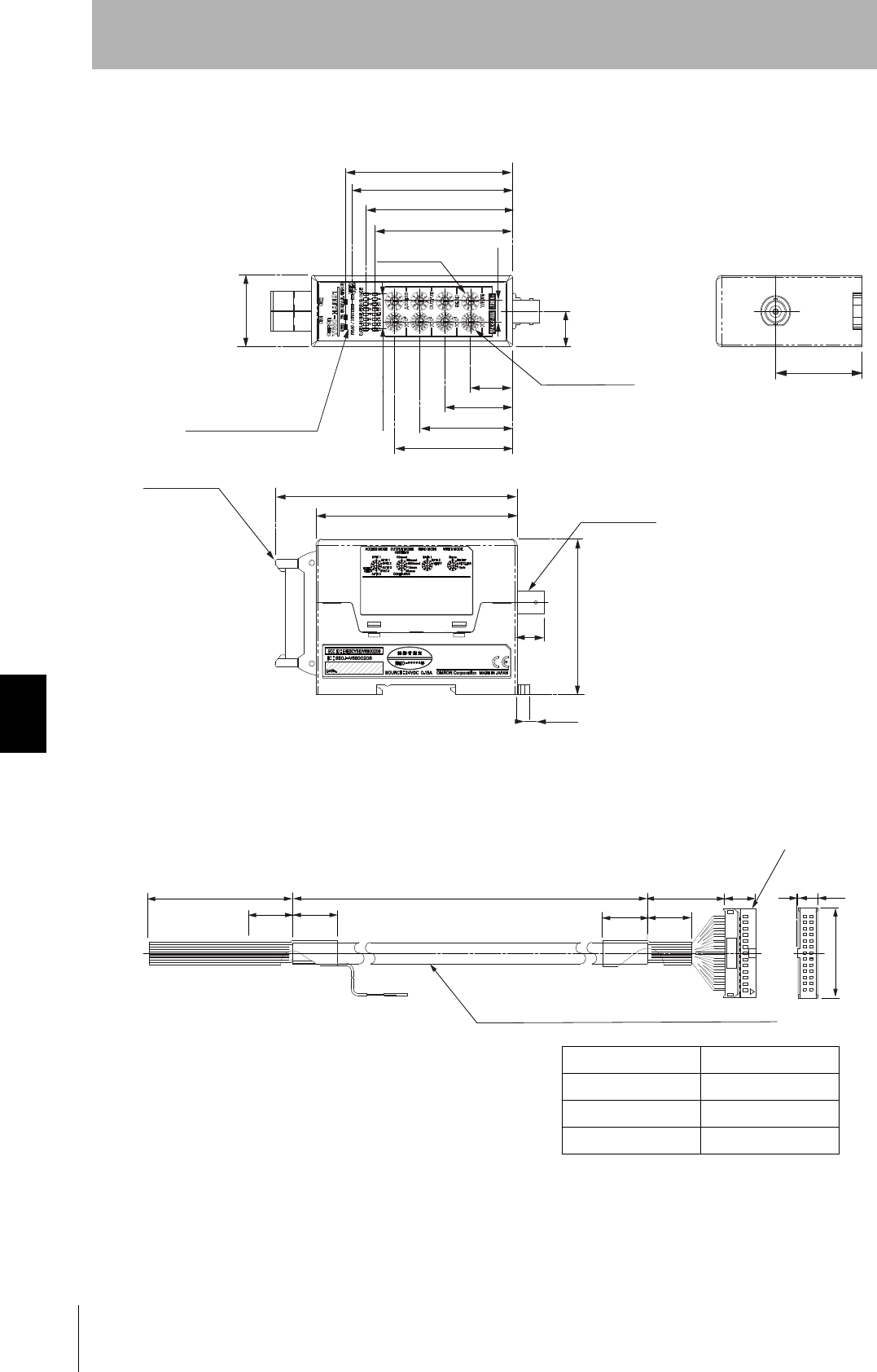
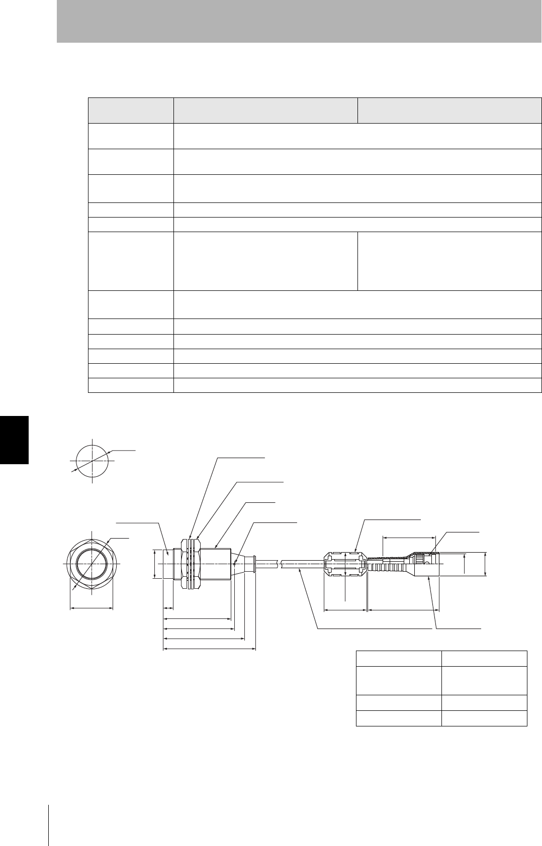
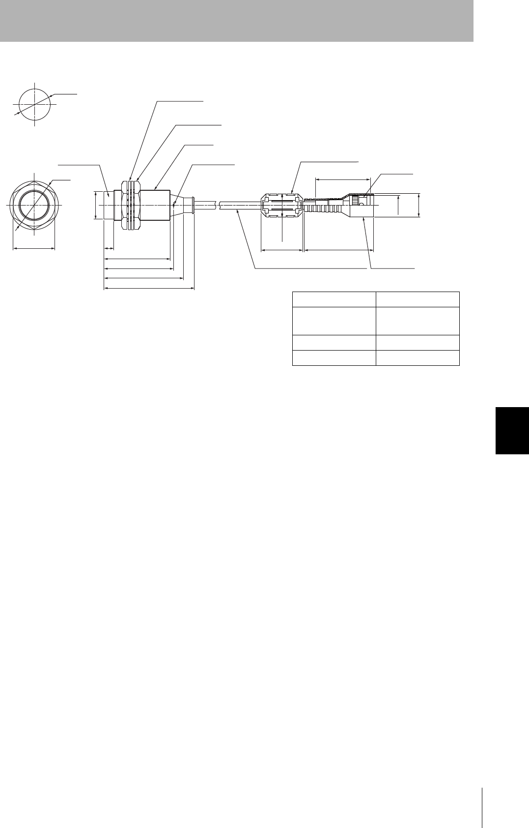
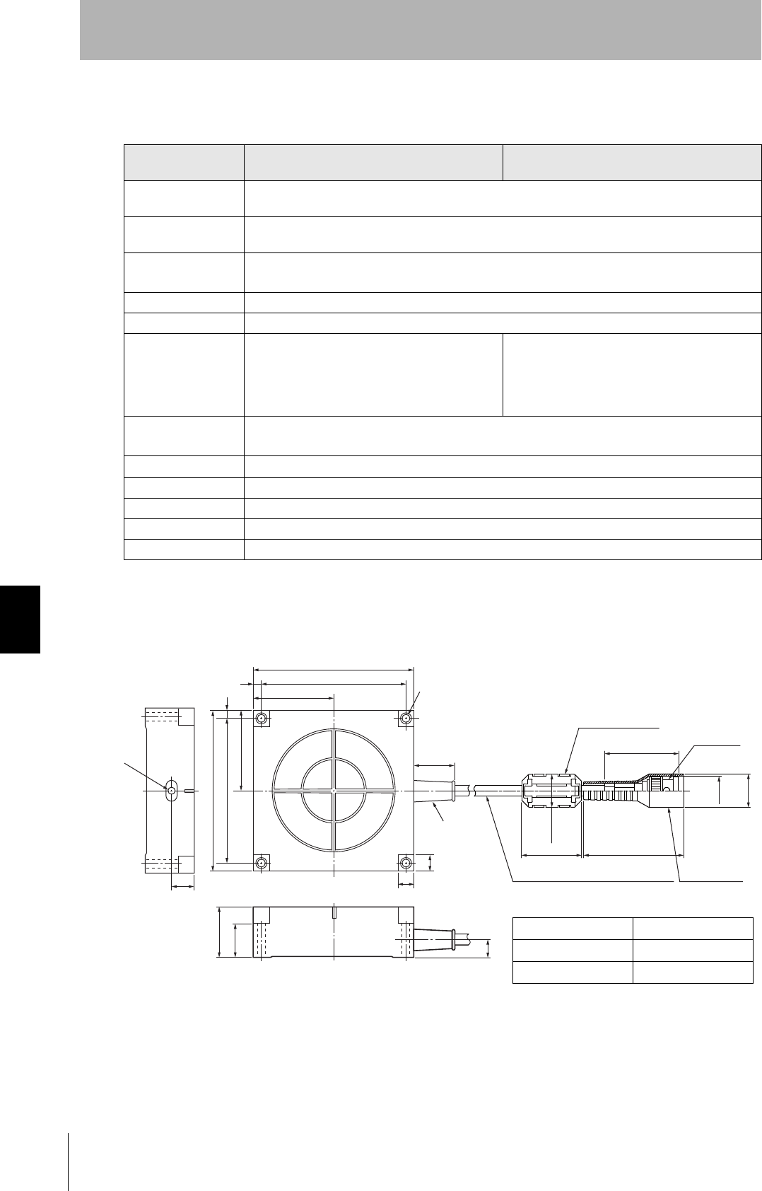
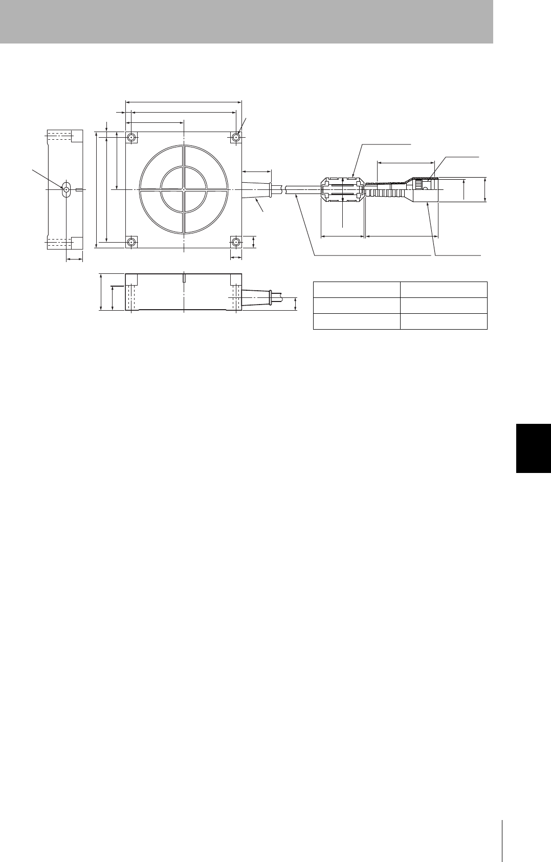
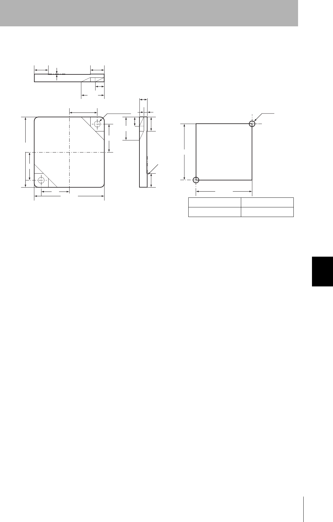
■Dimensions
V680-HAM91/-HAM81
Interface cable(optional)
V680-A60 2M/5M/10M
8.7
74.8
71.8
65.75
61.75
4-SWITCH
30
14.74
21-OPERATION
INDICATOR
7 × 2.1 = 14.7
4-SWITCH
18.95
30.25
41.55
52.85
108.26
90
CONNECTOR
65
12
(5.5)
38.5
(UNIT:mm)
CONNECTOR
(UNIT:mm)
320 20 ± 5 20 ± 5 20 ± 5 20 ± 5
35 ± 5 14.4 16.
37.6
XG5M-2632-N
VINYL INSULATED ROUND CORD
9 Dia. (7/0.2 Dia.) 23CORES
L1 0
+50
Model L1 Length (mm)
V680-A60 2M 2000
V680-A60 5M 5000
V680-A60 10M 10000
*The connector is a non-watertight type type.
*The cable the greatest extension distance is 10M.
111
RFID System
User's Manual
Section 7 Specification
Section 7
Chemical Resistance
Antenna
V680-HS51
General Specifications
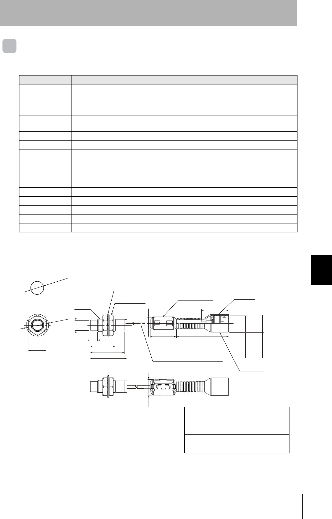
Dimension
Item Model V680-HS51
Ambient operating
temperature
−10 to 60°C (with no icing)
Ambient storage tem-
perature
−25 to 75°C (with no icing)
Ambient operating
humidity
35% to 95% (with no condensation)
Insulation resistance 20 MΩ min. (at 500 VDC) between connector terminals and case
Dielectric strength 1,000 VAC, 50/60 Hz for 1 min between connector terminals and case
Degree of protection IP67.(IEC60529)
In-house standard for antenna oil resistance (former JEM standard equivalent to IP67g)
Note: The connectors are not waterproof.
Dielectric strength 10 to 2,000 Hz, 1.5-mm double amplitude, acceleration: 150 m/s2, 10 sweeps in each of 3 axis direc-
tions (up/down, left/right, and forward/backward) for 15 minutes each
Shock resistance 1,000 m/s2, 3 times each in 6 directions (Total: 18 times)
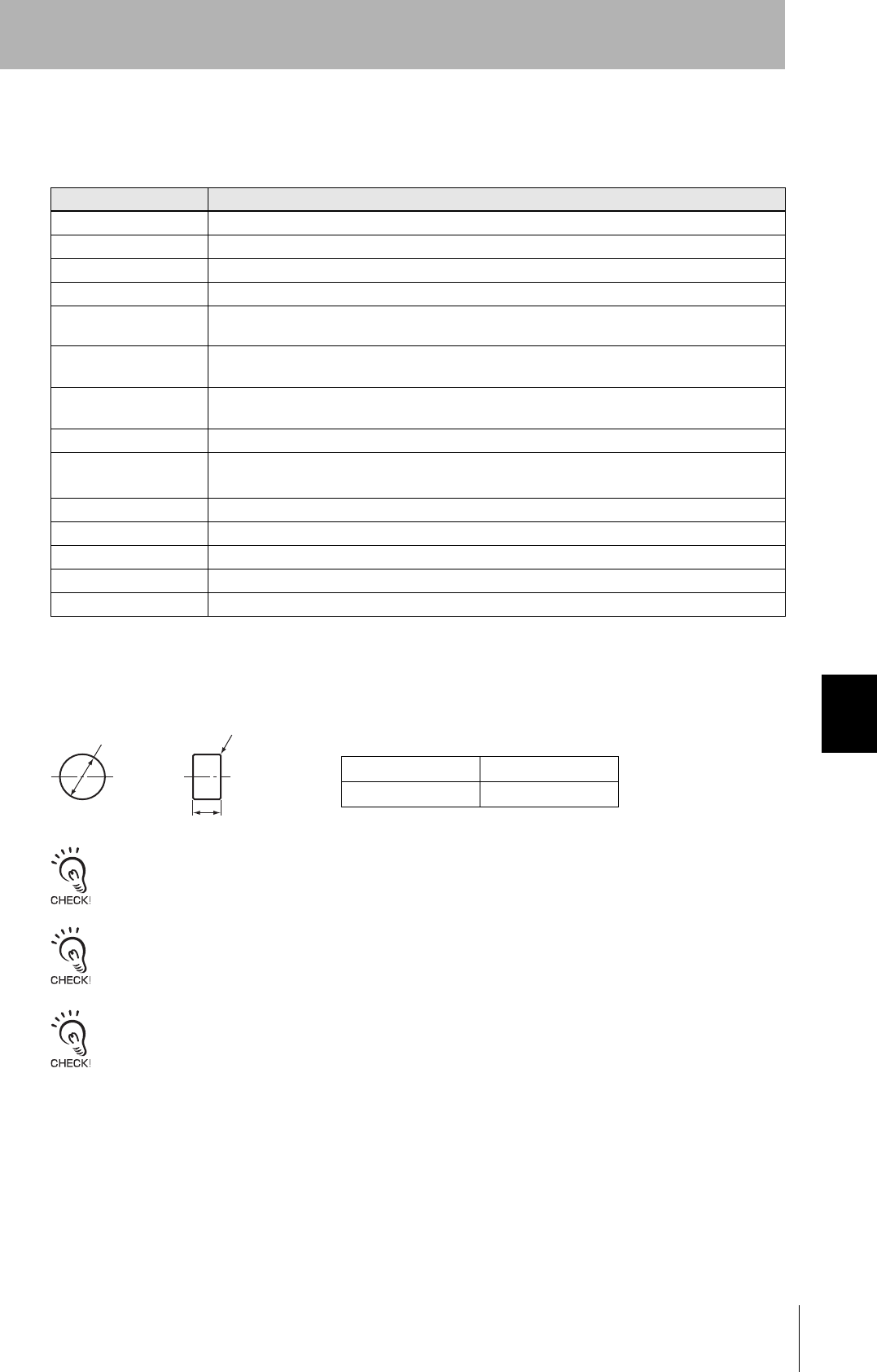
Dimensions M12 × 35 mm
Material ABS resin, brass, and epoxy resin filler
Weight Approx. 55 g
Cable length Standard lengths of 2 m
Case material Brass
Communications
surface
ABS resin
Fill resin Epoxy resin
Cable PVC (black)
17
Mounting Hole Dimensions
12.5 dia.
21 dia.
M12 × 1
Toothed washer
Two lock nuts
7
24
33
35
9.6 dia.
12
15
(14.5 dia.)
(16.8 dia.)
フェライトコア Connector
Coaxial cable, 2.9 dia.,
standard length: 2m
Insulation cover
25 50
26.2
(単位 : mm)
112
Section 7 Specification
RFID System
User's Manual
Section 7
Chemical Resistance
V680-HS52-W/R
General Specifications
Dimensions
V680-HS52-W
Item Model V680-HS52-W
(Standard cable, waterproof connector)
V680-HS52-R
(Flexible cable, non-waterproof connector)
Ambient operating
temperature
−10 to 60°C (with no icing)
Ambient storage
temperature
−25 to 75°C (with no icing)
Ambient operating
humidity
35% to 95% (with no condensation)
Insulation resistance 20 MΩ min. (at 500 VDC) between connector terminals and case
Dielectric strength 1,000 VAC, 50/60 Hz for 1 min between connector terminals and case
Degree of protection IP67 (IEC60529)
In-house standard for antenna oil resistance
(former JEM standard equivalent to IP67g)
Note: The connector specifications are IP67 and
IP65 (IEC 60529).
IP67 (IEC60529)
In-house standard for antenna oil resistance
(former JEM standard equivalent to IP67g)
Note: The connectors are not waterproof.
Dielectric strength 10 to 500 Hz, 1.5-mm double amplitude, acceleration: 100 m/s2, 10 sweeps in each of 3 axis directions
(up/down, left/right, and forward/backward) for 8 minutes each
Shock resistance 500 m/s2, 3 times each in 6 directions (Total: 18 times)
Dimensions M22 × 65 mm
Material ABS resin, brass, and epoxy resin filler
Weight Approx. 850 g (with 12.5 m cable)
Cable length Standard lengths of 2 and 12.5 m
Case material Brass
Communications
surface
ABS resin
Fill resin Epoxy resin
Cable PVC (gray)
22.5 dia.
Mounting Hole Dimensions
Antenna
35 dia.
30
Two toothed washers
Two lock nuts
M22 × 1
Operation indicator Ferrite core
Connector
37
7
47.6
50
57
65
30 50
19.8 dia.
16.5 dia.
14.5 dia.
16.8 dia.
Coaxial cable, 5.5 dia.
standard length: 2m Insulation
cover
(単位 : mm)
113
RFID System
User's Manual
Section 7 Specification
Section 7
Chemical Resistance
V680-HS52-R
Case material Brass
Communications
surface
ABS resin
Fill resin Epoxy resin
Cable PVC (black)
22.5 dia.
Mounting Hole Dimensions
Antenna
35 dia.
30
Two toothed washers
Two lock nuts
M22 × 1
Operation indicator Ferrite core
Connector
(39.5)
7
47.6
50
57
65
30 50
19.8 dia.
16.5 dia.
14.5 dia.
16.8 dia.
Coaxial cable, 5.3 dia.
standard length: 2m Insulation
cover
(単位 : mm)
114
Section 7 Specification
RFID System
User's Manual
Section 7
Chemical Resistance
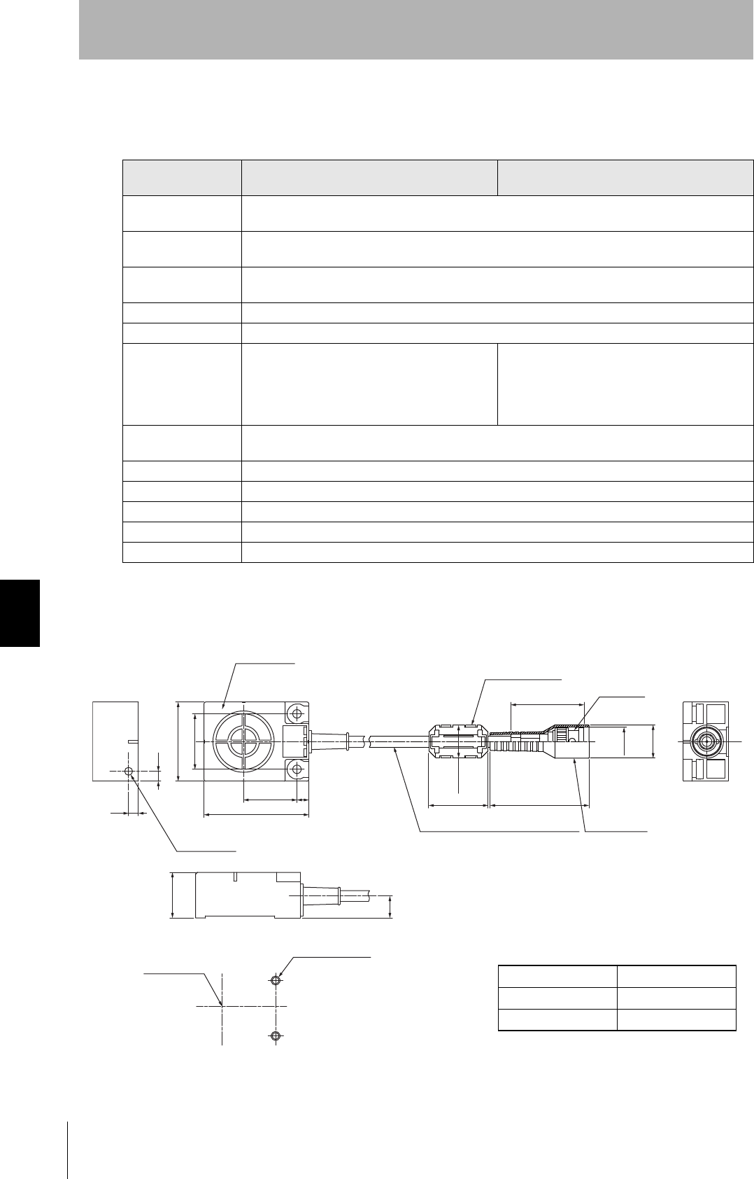
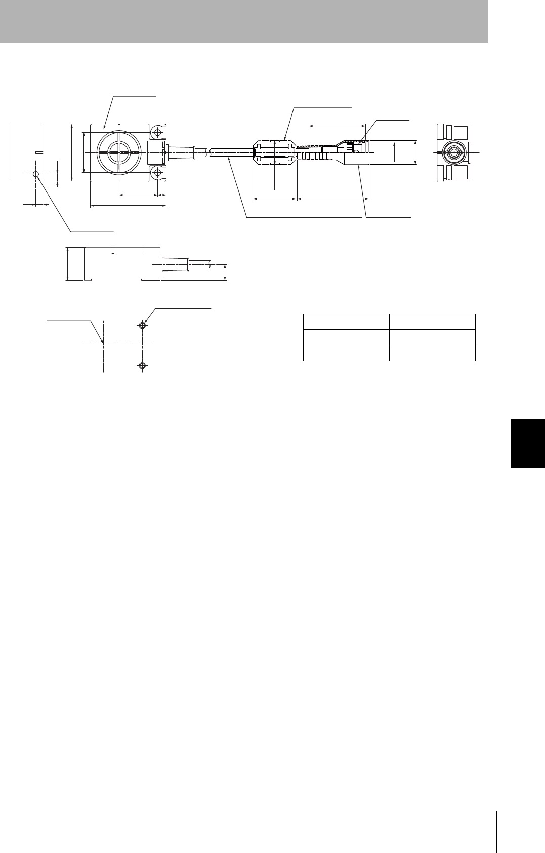
V680-HS63-W/R
General Specifications
Dimensions
V680-HS63-W
Item Model V680-HS63-W
(Standard cable, waterproof connector)
V680-HS63-R
(Flexible cable, non-waterproof connector)
Ambient operating
temperature
−10 to 60°C (with no icing)
Ambient storage
temperature
−25 to 75°C (with no icing)
Ambient operating
humidity
35% to 95% (with no condensation)
Insulation resistance 20 MΩ min. (at 500 VDC) between cable terminals and case
Dielectric strength 1,000 VAC, 50/60Hz for 1 min between cable terminals and case
Degree of protection IP67 (IEC60529)
In-house standard for antenna oil resistance
(former JEM standard equivalent to IP67g)
Note: The connector specifications are IP67 and
IP65 (IEC 60529).
IP67 (IEC60529)
In-house standard for antenna oil resistance
(former JEM standard equivalent to IP67g)
Note: The connectors are not waterproof.
Vibration resistance 10 to 500 Hz, 1.5-mm double amplitude, acceleration: 100 m/s2, 10 sweeps in each of 3 axis directions
(up/down, left/right, and forward/backward) for 11 minutes each
Shock resistance 500 m/s2, 3 times each in 6 directions (Total: 18 times)
Dimensions 40 × 53 × 23 mm
Material ABS resin case, epoxy resin filler
Weight Approx. 850 g (with 12.5 m cable)
Cable length Standard lengths of 2 and 12.5 m
Case material ABS resin
Fill resin Epoxy resin
Cable PVC (gray)
Note: Mounting Hole Dimensions
Antenna
40
6
Operation indicator
Ferrite core
Connector
37
27
53
530 50
16.5 dia.
14.5 dia.
16.8 dia.
Coaxial cable, 5.5 dia.
standard length: 2m Insulation cover
5
2 8 ± 0.1
Coil center
Two, M4 or 4.5 dia. holes
(UNIT: mm)
23
11
115
RFID System
User's Manual
Section 7 Specification
Section 7
Chemical Resistance
V680-HS63-W
Case material ABS resin
Fill resin Epoxy resin
Cable PVC (black)
Note: Mounting Hole Dimensions
Antenna
40
6
Operation indicator
Ferrite core
Connector
37
27
53
530 50
16.5 dia.
14.5 dia.
16.8 dia.
Coaxial cable, 5.3 dia.
standard length: 2m Insulation cover
5
2 8 ± 0.1
Coil center
Two, M4 or 4.5 dia. holes
(UNIT: mm)
23
11
116
Section 7 Specification
RFID System
User's Manual
Section 7
Chemical Resistance
V680-HS65-W/R
General Specifications
Dimensions
V680-HS65-W
Item Model V680-HS65-W
(Standard cable, waterproof connector)
V680-HS65-R
(Flexible cable, non-waterproof connector)
Ambient operating
temperature
−25 to 70°C (with no icing)
Ambient storage
temperature
−40 to 85°C (with no icing)
Ambient operating
humidity
35% to 95% (with no condensation)
Insulation resistance 20 MΩ min. (at 500 VDC) between connector terminals and case
Dielectric strength 1,000 VAC, 50/60 Hz for 1 min between connector terminals and case
Degree of protection IP67 (IEC60529)
In-house standard for antenna oil resistance
(former JEM standard equivalent to IP67g)
Note: The connector specifications are IP67 and
IP65 (IEC 60529).
IP67 (IEC60529)
In-house standard for antenna oil resistance
(former JEM standard equivalent to IP67g)
Note: The connectors are not waterproof.
Dielectric strength 10 to 500 Hz, 1.5-mm double amplitude, acceleration: 100 m/s2, 10 sweeps in each of 3 axis directions
(up/down, left/right, and forward/backward) for 11 minutes each
Shock resistance 500 m/s2, 3 times each in 6 directions (Total: 18 times)
Dimensions 100 × 100 × 30 mm
Material ABS resin case, epoxy resin filler
Weight Approx. 1100 g (with 12.5 m cable)
Cable length Standard lengths of 2 and 12.5 m
Case material ABS resin
Fill resin Epoxy resin
Cable PVC (gray)
100
Operation
indicator
Ferrite core
Connector
37
10
10
14
30 50
16.5 dia.
14.5 dia.
16.8 dia.
Coaxial cable, 5.5 dia.
standard length: 2m Insulation
cover
5
90 ± 0.2
Bushing
4-4.5 dia.
(UNIT: mm)
50
30
20
100
590 ± 0.2
50
11
(Mounting holes)
117
RFID System
User's Manual
Section 7 Specification
Section 7
Chemical Resistance
V680-HS65-W
Case material ABS resin
Fill resin Epoxy resin
Cable PVC (black)
100
Operation
indicator
Ferrite core
Connector
37
10
10
14
30 50
16.5 dia.
14.5 dia.
16.8 dia.
Coaxial cable, 5.3 dia.
standard length: 2m Insulation
cover
5
Bushing
4-4.5 dia.
(UNIT: mm)
50
30
20
100
590 ± 0.2
50
11
(Mounting holes)
90 ± 0.2
118
Section 7 Specification
RFID System
User's Manual
Section 7
Chemical Resistance
ID Tag
V680-D1KP52MT
General Specifications
Note: After string data at high temperatures, rewrite the data even if changes are not required, In this manual, high
temperatures are those exceeding 125°C up to 180°C.
Dimensions
When embedding the V680-D1KP52MT into a metal surface, use the V680-HS51, V680-HS52 Antenna.
Transmission will not be possible if the V680-HS63 Antenna is used.
The side with the markings is the communications surface. Mount the Tag with this side facing the Antenna.
The ID code is written in the memory of the Tag and may be affected by data retention characteristics at high tempera-
tures. Take suitable precautions when using the READ ID command for Tags operating at high temperatures.
Item Model V680-D1KP52MT
Memory capacity 1,000 bytes (user area)
Memory type EEPROM
Data backup time 10 years after writing (85°C or less), 0.5 years after writing (85°C to 125°C)
Total data backup time at high temperatures exceeding 125°C is 10 houres (See note.)
Memory longevity 100,000 times per block (25°C)
Ambient operating tem-
perature when communi-
cating
−25 to 85°C (with no icing)
Ambient operating tem-
perature when not com-
municating
−40 to125°C (with no icing)
Ambient storage temper-
ature
−40 to 125°C (with no icing)
Ambient operating
humidity
35% to 95%
Degree of protection IP68 (IEC 60529)
In-house standard for antenna oil resistance (former JEM standard equivalent to IP67g)
Vibration resistance 10 to 2,000 Hz, 1.5-mm double amplitude, acceleration: 150 m/s2, 10 sweeps each in X, Y, and Z
directions for 15 minutes each
Shock resistance 500 m/s2, 3 times each in X, Y, and Z directions (Total: 18 times)
Dimensions 8 dia. × 5 mm
Materials Case: PPS resin, Fill resin: Epoxy resin
Weight Approx. 0.5 g
Metal countermeasures Yes
Case material PPS resin
Fill resin Epoxy resin
8R0.2
0
-0.1
50
-0.1 (UNIT: mm)
dia.

119
RFID System
User's Manual
Section 7 Specification
Section 7
Chemical Resistance
Tag Heat Resistivity
• Storing Tags under high temperatures will adversely affect the performance of the internal parts and
the service life of the Tags.
・An LTPD of 10% was determined during the evaluation for Tags that reached the end of their life after
testing under the following test conditions.
LTPD: Lot tolerance percent defective
The lower limit of the malfunction rate for lots to be considered unacceptable during reliability testing.
Heat cycle −10°C/+150°C, 30 minutes each for 1,000 cycles
−100°C/+180°C,30 minutes each for 200 cycles
High temperatures +150°C, 1,000 hours
+180°C, 200 hours
120
Section 7 Specification
RFID System
User's Manual
Section 7
Chemical Resistance
V680-D1KP66T/-D1KP66MT
General Specifications
Note: After string data at high temperatures, rewrite the data even if changes are not required, In this manual, high
temperatures are those exceeding 125°C up to 180°C.
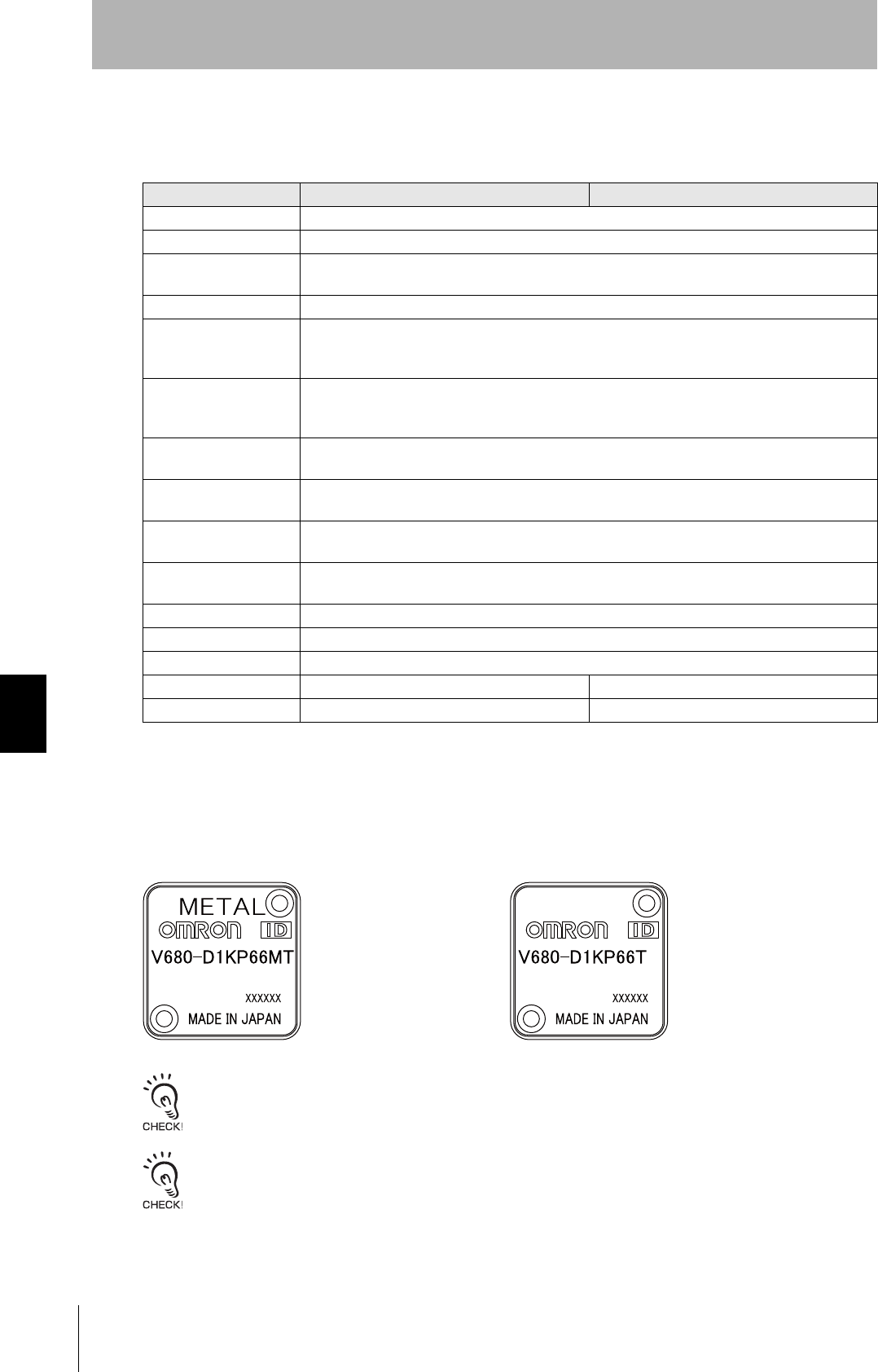
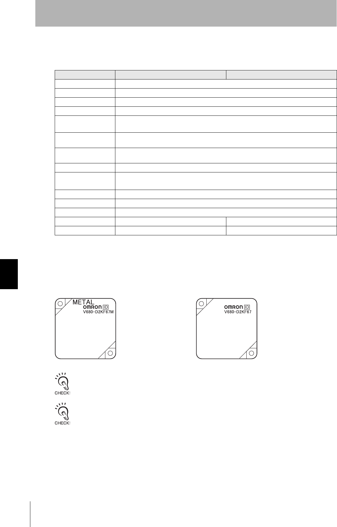
The V680-D1KP66MT is designed to be mounted directly to metal. The V680-D1KP66T and V680-
D1KP66MT markings are shown in the following diagrams.
The side with the markings is the communications surface. Mount the Tag with this side facing the Antenna.
The ID code is written in the memory of the Tag and may be affected by data retention characteristics at high tempera-
tures. Take suitable precautions when using the READ ID command for Tags operating at high temperatures.
Item Model V680-D1KP66T V680-D1KP66MT
Memory capacity 1,000 bytes (user area)
Memory type EEPROM
Data backup time 10 years after writing (85°C or less), 0.5 years after writing (85°C to 125°C)
Total data backup time at high temperatures exceeding 125°C is 10 houres (See note.)
Memory longevity 100,000 times per block (25°C)
Ambient operating tem-
perature when communi-
cating
−25 to 85°C (with no icing)
Ambient operating tem-
perature when not com-
municating
−40 to125°C (with no icing)
Ambient storage temper-
ature
−40 to 125°C (with no icing)
Ambient operating
humidity
35% to 95%
Degree of protection IP68 (IEC 60529)
In-house standard for antenna oil resistance (former JEM standard equivalent to IP67g)
Vibration resistance 10 to 2,000 Hz, 1.5-mm double amplitude, acceleration: 150 m/s2,10 sweeps each in X, Y, and Z
directions for 15 minutes each
Shock resistance 500 m/s2, 3 times each in X, Y, and Z directions (Total: 18 times)
Dimensions 34 × 34 × 3.5 mm
Materials Case: PPS resin
Weight Approx. 6 g Approx. 7.5 g
Metal countermeasures None Yes
•V680-D1KP66MT •V680-D1KP66T
121
RFID System
User's Manual
Section 7 Specification
Section 7
Chemical Resistance
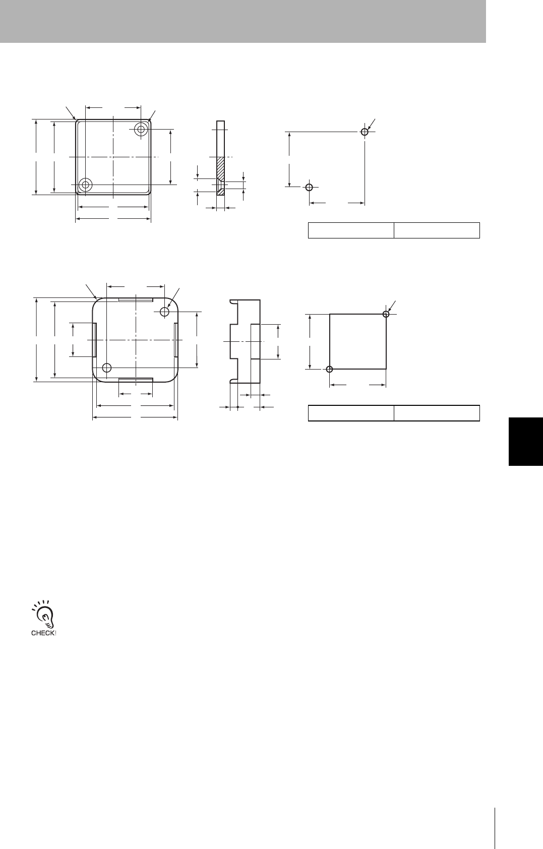
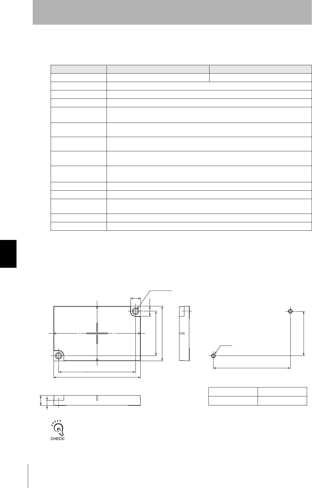
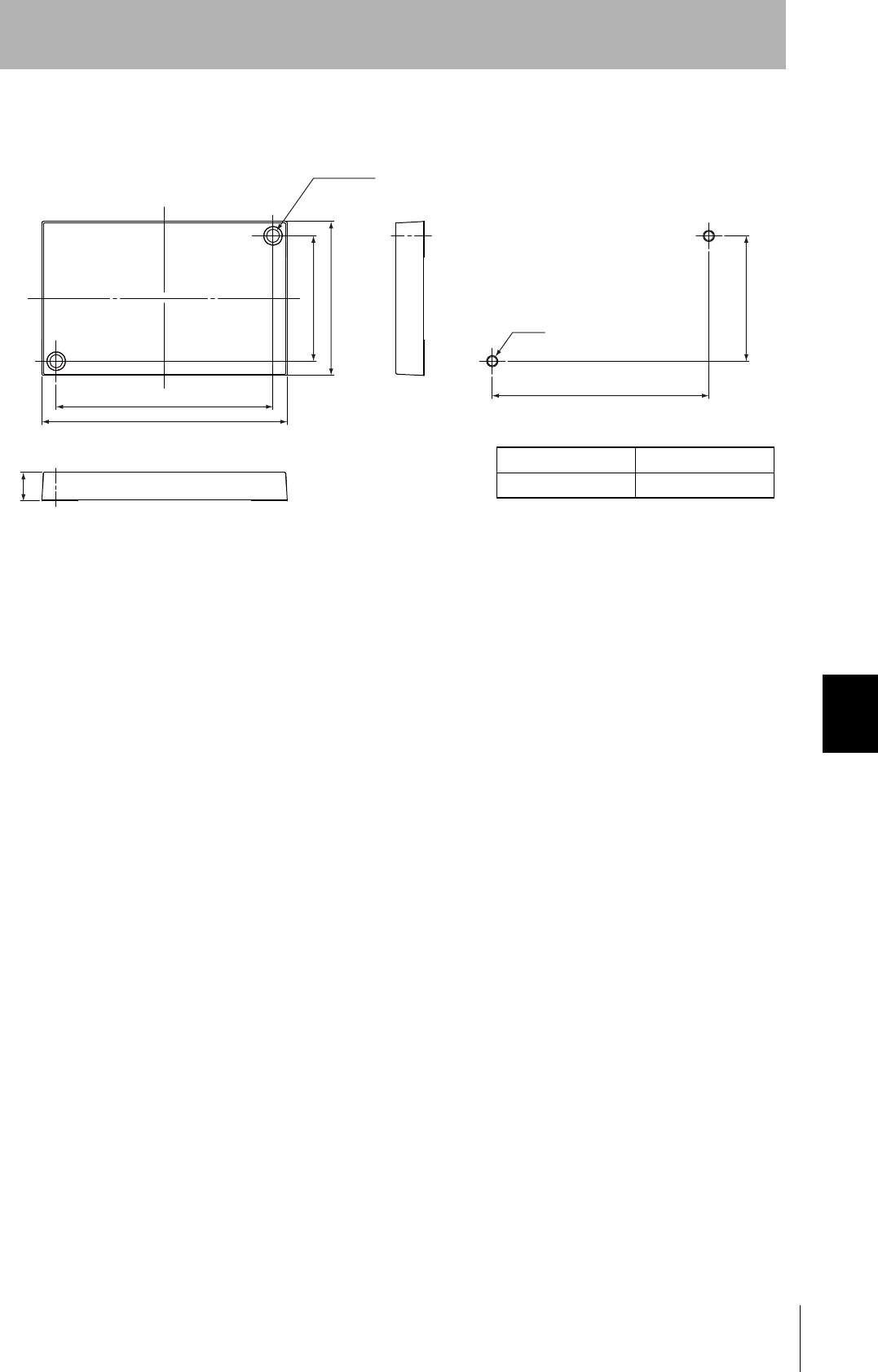
Dimensions
V680-D1KP66T/-D1KP66MT
V600-A86(Attachment)
Tag Heat Resistivity
• Storing Tags under high temperatures will adversely affect the performance of the internal parts and
the service life of the Tags.
・An LTPD of 10% was determined during the evaluation for Tags that reached the end of their life after
testing under the following test conditions.
LTPD: Lot tolerance percent defective
The lower limit of the malfunction rate for lots to be considered unacceptable during reliability testing.
Heat cycle −10°C/+150°C, 30 minutes each for 1,000 cycles
−100°C/+180°C,30 minutes each for 200 cycles
High temperatures +150°C, 1,000 hours
+180°C, 200 hours
Case material PPS resin
34 32
34
32
Four, R4 25 ± 0.2
25 ± 0.2
Four, R8
3.5 ± 0.2
Two, 6 dia.
Two, 3.5 dia. 25 ± 0.2
25 ± 0.2
Two, M3
Mounting Hole Dimensions (UNIT: mm)
Case material PPS resin
37 34 15
37
34
15
25 ± 0.2
25 ± 0.2
Four, R5.5 Two, 4 dia.
16
10
25 ± 0.2
25 ± 0.2
Two, M3
3.5
4
(UNIT: mm)
122
Section 7 Specification
RFID System
User's Manual
Section 7
Chemical Resistance
V680-D1KP66T-SP
General Specifications
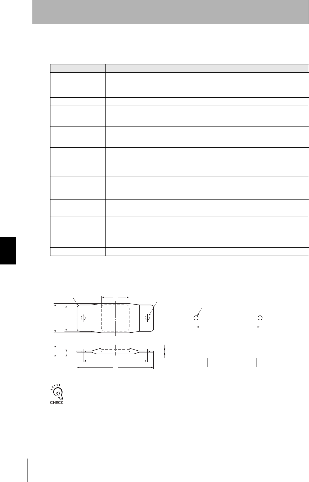
Dimensions
The side with the markings is the communications surface. Mount the Tag with this side facing the Antenna.
Item Model V680-D1KP66T-SP
Memory capacity 1,000 bytes (user area)
Memory type EEPROM
Data backup time 10 years after writing (85°C or less)
Memory longevity 100,000 times per block (25°C)
Ambient operating tem-
perature when communi-
cating
−25 to 70°C (with no icing)
Ambient operating tem-
perature when not com-
municating
−40 to110°C (with no icing)
Ambient storage temper-
ature
−40 to 110°C (with no icing)
Ambient operating
humidity
35% to 95%
Degree of protection IP67
Vibration resistance 10 to 2,000 Hz, 1.5-mm double amplitude, acceleration: 150 m/s2,10 sweeps each in X, Y, and Z
directions for 15 minutes each
Shock resistance 500 m/s2, 3 times each in X, Y, and Z directions (Total: 18 times)
Dimensions 95 × 36.5 × 6.5 mm (excluding protruding parts)
Materials External coatiog: Fluororesin (PFA)
Tag body: PPS resin
Weight Approx. 20 g
Mounting method Two M5 screws
Metal countermeasures None
(UNIT: mm)
Case material PFA resin
Two, M5
80 ± 0.2
Mounting Hole Dimensions
Two, 5.5 dia.
mounting holes
80 ± 0.2
95
34
34
36.5
6.5
2.5mm max.
1.3
123
RFID System
User's Manual
Section 7 Specification
Section 7
Chemical Resistance
V680-D2KF52M
General Specifications
Dimensions
When embedding the V680-D2KF52M into a metal surface, use the V680-HS51/-HS52 Antenna.
Transmission will not be possible if the V680-HS63 Antenna is used.
The side with the markings is the communications surface. Mount the Tag with this side facing the Antenna.
The ID code is written in the memory of the Tag and may be affected by data retention characteristics at high tempera-
tures. Take suitable precautions when using the READ ID command for Tags operating at high temperatures.
Item Model V680-D2KF52M
Memory capacity 2,000 bytes (user area)
Memory type FRAM
Data backup time 10 years after writing (55°C or less)
Memory longevity 10 billion times per block. Access frequency (See note) : 10 billion times
Ambient operating
temperature
−25 to 85°C (with no icing)
Ambient storage
temperature
−40 to 85°C (with no icing)
Ambient operating
humidity
35% to 85%
Degree of protection IP67 (IEC 60529)
Vibration resistance 10 to 2,000 Hz, 1.5-mm double amplitude, acceleration: 150 m/s2, 10 sweeps each in X, Y, and Z
directions for 15 minutes each
Shock resistance 500 m/s2, 3 times each in X, Y, and Z directions (Total: 18 times)
Dimensions 8 dia. × 5 mm
Materials Case: PPS resin, Fill resin: Epoxy resin
Weight Approx. 0.5 g
Metal countermeasures Yes
Case material PPS resin
Fill resin Epoxy resin
8R0.2
0
-0.1
50
-0.1 (UNIT: mm)
dia.
124
Section 7 Specification
RFID System
User's Manual
Section 7
Chemical Resistance
V680-D2KF67/-D2KF67M
General Specifications
Note: The total communication frequency of the Read or Write is called an access frequency.
The V680-D2KF67M is designed to be mounted directly to metal. The V680-D2KF67 and V680-
D2KF67M markings are shown in the following diagrams.
The side with the markings is the communications surface. Mount the Tag with this side facing the Antenna.
The ID code is written in the memory of the Tag and may be affected by data retention characteristics at high tempera-
tures. Take suitable precautions when using the READ ID command for Tags operating at high temperatures.
Item Model V680-D2KF67 V680-D2KF67M
Memory capacity 2,000 bytes (user area)
Memory type FRAM
Data backup time 10 years after writing (55°C or less)
Memory longevity 10 billion times per block. Access frequency (See note) : 10 billion times
Ambient operating
temperature
−25 to 85°C (with no icing)
Ambient storage
temperature
−40 to 85°C (with no icing)
Ambient operating
humidity
35% to 85%
Degree of protection IP67 (IEC 60529)
Vibration resistance 10 to 2,000 Hz, 1.5-mm double amplitude, acceleration: 150 m/s2,10 sweeps each in X, Y, and Z
directions for 15 minutes each
Shock resistance 500 m/s2, 3 times each in X, Y, and Z directions (Total: 18 times)
Dimensions 40 × 40 × 4.5 mm
Materials Case: ABS resin
Weight Approx. 6.5 g Approx. 7 g
Metal countermeasures None Yes
•V680-D2KF67M •V680-D2KF67
125
RFID System
User's Manual
Section 7 Specification
Section 7
Chemical Resistance
Dimensions
Case material ABS resin
Fill resin Epoxy resin
(UNIT: mm)88
0.2
5.2
13.2
16
16
16
16
40 +0.1
-0.5
40 +0.1
-0.5
Two, 3.5 dia.
mounting holes
4.5
2
8
5.2
13.2
8
Mounting
refernce
surface
32 ± 0.2
32 ± 0.2
Mounting Hole Dimensions
Two, M3
126
Section 7 Specification
RFID System
User's Manual
Section 7
Chemical Resistance
V680-D8KF68/-D32KF68
General Specifications
Note: The total communication frequency of the Read or Write is called an access frequency.
Dimensions
V680-D8KF68/-D32KF68
The side with the markings is the communications surface. Mount the Tag with this side facing the Antenna.
Item Model V680-D8K68 V680-D32KF68
Memory capacity 8,192 bytes (user area) 32,744 bytes (user area)
Memory type FRAM
Data backup time 10 years after writing (70°C max.), 6 years after writing (85°C max.)
Memory longevity 10 billion times per block (85°C or less). Access frequency (See note): 10 billion times
Ambient operating
temperature
−20 to 85°C (with no icing)
Ambient storage
temperature
−40 to 85°C (with no icing)
Ambient operating
humidity
35% to 85%
Degree of protection IP67 (IEC 60529)
In-house standard for oil resistance (former JEM standard equivalent to IP67g)
Vibration resistance 10 to 500 Hz, 1.5-mm double amplitude, acceleration: 100 m/s2, 10 sweeps each in X, Y, and Z
directions for 11 minutes each
Shock resistance 500 m/s2, 3 times each in X, Y, and Z directions (Total: 18 times)
Dimensions 86 × 54 × 10 mm
Materials Case: PBT resin
Fill resin: Epoxy resin
Weight Approx. 50 g
Metal countermeasures None
Case material PBT resin
Fill resin Epoxy resin
Two, 4.5 dia. (UNIT: mm)
mounting holes
10
10
44 ± 0.2
54
76 ± 0.2
86
Mounting Hole Dimensions
Two, M4
44
76
10
5
127
RFID System
User's Manual
Section 7 Specification
Section 7
Chemical Resistance
V680-A81(Attachment)
Case material PBT resin
Fill resin Epoxy resin
Two, 4.5 dia.
(UNIT: mm)
mounting holes
44 ± 0.2
54
76 ± 0.2
86
Mounting Hole Dimensions
Two, M4
44
76
10
128
Section 7 Characteristic data
RFID System
User's Manual
Section 7
Chemical Resistance
Characteristic data
Transmission Distance Specifications
V680-D1KP52MT
When embedding the V680-D1KP52MT into a metal surface, use the V680-HS51, V680-HS52 Antenna.
Transmission will not be possible if the V680-HS63 Antenna is used.
Measurement Conditions
Antenna ID Tag Communications distance
V680-HS51 V680-D1KP52MT Read 0.5 to 6.5 mm (Axis offset: ±2 mm)
Write 0.5 to 6.0 mm (Axis offset: ±2 mm)
V680-HS51 V680-D1KP52MT embedded in
metal (steel)
Read 0.5 to 3.5 mm (Axis offset: ±2 mm)
Write 0.5 to 3.0 mm (Axis offset: ±2 mm)
V680-HS52 V680-D1KP52MT Read 0.5 to 9.0 mm (Axis offset: ±2 mm)
Write 0.5 to 8.5 mm (Axis offset: ±2 mm)
V680-HS52 V680-D1KP52MT embedded in
metal (steel)
Read 0.5 to 4.5 mm (Axis offset: ±2 mm)
Write 0.5 to 4.0 mm (Axis offset: ±2 mm)
V680-HS63 V680-D1KP52MT Read 0.5 to 12.0 mm (Axis offset: ±2 mm)
Write 0.5 to 9.5 mm (Axis offset: ±2 mm)
V680-HS51
V680-D1KP52MT
Non-metallic material
(Examples: Resin, plastic, wood, etc.)
Metal
V680-HS52
V680-D1KP52MT
Non-metallic material
(Examples: Resin, plastic, wood, etc.)
Non-metallic material
V680-HS51
V680-D1KP52MT
Metal
V680-HS52
V680-D1KP52MT
Non-metallic material
Metal
Metal
V680-HS63
V680-D1KP52MT
Non-metallic material
(Examples: Resin, plastic, wood, etc.)
Non-metallic material

129
RFID System
User's Manual
Section 7 Characteristic data
Section 7
Chemical Resistance
V680-D1KP66T
Measurement Conditions
Antenna ID Tag Communications distance
V680-HS52 V680-D1KP66T Read 1.0 to 17.0 mm (Axis offset: ±2 mm)
Write 1.0 to 17.0 mm (Axis offset: ±2 mm)
V680-HS63 V680-D1KP66T Read 5.0 to 30.0 mm (Axis offset: ±10 mm)
Write 5.0 to 25.0 mm (Axis offset: ±10 mm)
V680-HS65 V680-D1KP66T Read 5.0 to 47.0 mm (Axis offset: ±10 mm)
Write 5.0 to 42.0 mm (Axis offset: ±10 mm)
V680-D1KP66T
Non-metallic material
(Examples: Resin, plastic, wood, etc.)
V680-HS52
Non-metallic material
(Examples: Resin, plastic, wood, etc.)
Non-metallic material
V680-HS63
Non-metallic material
(Examples: Resin, plastic, wood, etc.)
Metal
V680-D1KP66T
Non-metallic material
V680-D1KP66T
V680-HS65

130
Section 7 Characteristic data
RFID System
User's Manual
Section 7
Chemical Resistance
V680-D1KP66MT
Measurement Conditions
Antenna ID Tag Communications Distance
V680-HS52 V680-D1KP66MT
with metal on back surface (steel)
Read 1.0 to 16.0 mm (Axis offset: ±2 mm)
Write 1.0 to 14.0 mm (Axis offset: ±2 mm)
V680-HS63 V680-D1KP66MT
with metal on back surface (steel)
Read 5.0 to 25.0 mm (Axis offset: ±10 mm)
Write 5.0 to 20.0 mm (Axis offset: ±10 mm)
V680-HS65 V680-D1KP66MT
with metal on back surface (steel)
Read 5.0 to 25.0 mm (Axis offset: ±10 mm)
Write 5.0 to 20.0 mm (Axis offset: ±10 mm)
V680-D1KP66MT
V680-HS52
Non-metallic material
V680-HS63
Metal
V680-D1KP66MT
Non-metallic material
V680-D1KP66MT
V680-HS65
Metal
Metal
Metal
131
RFID System
User's Manual
Section 7 Characteristic data
Section 7
Chemical Resistance
V680-D1KP66T-SP
Measurement Conditions
Antenna ID Tag Communications distance
V680-HS52 V680-D1KP66T-SP Read 1.0 to 17.0 mm (Axis offset: ±2 mm)
Write 1.0 to 17.0 mm (Axis offset: ±2 mm)
V680-HS63 V680-D1KP66T-SP Read 5.0 to 30.0 mm (Axis offset: ±10 mm)
Write 5.0 to 25.0 mm (Axis offset: ±10 mm)
V680-HS65 V680-D1KP66T-SP Read 5.0 to 47.0 mm (Axis offset: ±10 mm)
Write 5.0 to 42.0 mm (Axis offset: ±10 mm)
V680-D1KP66T-SP
Non-metallic material
(Examples: Resin, plastic, wood, etc.)
V680-HS52
Non-metallic material
(Examples: Resin, plastic, wood, etc.)
Non-metallic material
V680-HS63
Non-metallic material
(Examples: Resin, plastic, wood, etc.)
V680-D1KP66T-SP
Non-metallic material
V680-D1KP66T-SP
V680-HS65
Non-metallic material
132
Section 7 Characteristic data
RFID System
User's Manual
Section 7
Chemical Resistance
V680-D2KF52M
When embedding the V680-D2KF52M into a metal surface, use the V680-HS51/-HS52 Antenna.
Transmission will not be possible if the V680-HS63 Antenna is used.
Measurement Conditions
Antenna ID Tag Communications distance
V680-HS51 V680-D2KF52M Read 0.5 to 5.5 mm (Axis offset: ±2 mm)
Write 0.5 to 5.5 mm (Axis offset: ±2 mm)
V680-HS51 V680-D2KF52M embedded in
metal (steel)
Read 0.5 to 3.5 mm (Axis offset: ±2 mm)
Write 0.5 to 3.5 mm (Axis offset: ±2 mm)
V680-HS52 V680-D2KF52M Read 0 to 8.0 mm (Axis offset: ±2 mm)
Write 0 to 8.0 mm (Axis offset: ±2 mm)
V680-HS52 V680-D2KF52M embedded in
metal (steel)
Read 0 to 3.0 mm (Axis offset: ±2 mm)
Write 0 to 3.0 mm (Axis offset: ±2 mm)
V680-HS63 V680-D2KF52M Read 0 to 9.5 mm (Axis offset: ±2 mm)
Write 0 to 9.5 mm (Axis offset: ±2 mm)
V680-HS51
V680-D2KF52M
Non-metallic material
(Examples: Resin, plastic, wood, etc.)
Metal
V680-HS52
V680-D2KF52M
Non-metallic material
(Examples: Resin, plastic, wood, etc.)
Non-metallic material
V680-HS51
V680-D2KF52M
Metal
V680-HS52
V680-D2KF52M
Non-metallic material
Metal
Metal
V680-HS63
V680-D2KF52M
Non-metallic material
(Examples: Resin, plastic, wood, etc.)
Non-metallic material

133
RFID System
User's Manual
Section 7 Characteristic data
Section 7
Chemical Resistance
V680-D2KF67
Measurement Conditions
Antenna ID Tag Communications distance
V680-HS52 V680-D2KF67 Read 0 to 17.0 mm (Axis offset: ±2 mm)
Write 0 to 17.0 mm (Axis offset: ±2 mm)
V680-HS63 V680-D2KF67 Read 7.0 to 30.0 mm (Axis offset: ±10 mm)
Write 7.0 to 30.0 mm (Axis offset: ±10 mm)
V680-HS65 V680-D2KF67 Read 0 to 42.0 mm (Axis offset: ±10 mm)
Write 0 to 42.0 mm (Axis offset: ±10 mm)
V680-D2KF67
Non-metallic material
(Examples: Resin, plastic, wood, etc.)
V680-HS52
Non-metallic material
(Examples: Resin, plastic, wood, etc.)
Non-metallic material
V680-HS63
Non-metallic material
(Examples: Resin, plastic, wood, etc.)
Metal
V680-D2KF67
Non-metallic material
V680-D2KF67
V680-HS65
134
Section 7 Characteristic data
RFID System
User's Manual
Section 7
Chemical Resistance
V680-D2KF67M
Measurement Conditions
Antenna ID Tag Communications Distance
V680-HS52 V680-D2KF67M
with metal on back surface (steel)
Read 0 to 16.0 mm (Axis offset: ±2 mm)
Write 0 to 16.0 mm (Axis offset: ±2 mm)
V680-HS63 V680-D2KF67M
with metal on back surface (steel)
Read 6.0 to 25.0 mm (Axis offset: ±10 mm)
Write 6.0 to 25.0 mm (Axis offset: ±10 mm)
V680-HS65 V680-D2KF67M
with metal on back surface (steel)
Read 0 to 25.0 mm (Axis offset: ±10 mm)
Write 0 to 25.0 mm (Axis offset: ±10 mm)
V680-D2KF67M
V680-HS52
Non-metallic material
V680-HS63
Metal
V680-D2KF67M
Non-metallic material
V680-D2KF67M
V680-HS65
Metal
Metal
Metal
135
RFID System
User's Manual
Section 7 Characteristic data
Section 7
Chemical Resistance
V680-D8KF68/-D32KF68
Measurement Conditions
Antenna ID Tag Communications Distance
V680-HS63
V680-D8KF68 Read 5.0 to 45.0 mm (Axis offset: ±10 mm)
Write 5.0 to 45.0 mm (Axis offset: ±10 mm)
V680-D8KF68 (with ATTACHMENT, V680-A81)
with metal on back surface (steel)
Read 5.0 to 35.0 mm (Axis offset: ±10 mm)
Write 5.0 to 35.0 mm (Axis offset: ±10 mm)
V680-D32KF68 Read 5.0 to 45.0 mm (Axis offset: ±10 mm)
Write 5.0 to 45.0 mm (Axis offset: ±10 mm)
V680-D32KF68 (with ATTACHMENT, V680-A81)
with metal on back surface (steel)
Read 5.0 to 35.0 mm (Axis offset: ±10 mm)
Write 5.0 to 35.0 mm (Axis offset: ±10 mm)
V680-HS65
V680-D8KF68 Read 5.0 to 75.0 mm (Axis offset: ±10 mm)
Write 5.0 to 75.0 mm (Axis offset: ±10 mm)
V680-D8KF68 (with ATTACHMENT, V680-A81)
with metal on back surface (steel)
Read 5.0 to 55.0 mm (Axis offset: ±10 mm)
Write 5.0 to 55.0 mm (Axis offset: ±10 mm)
V680-D32KF68 Read 5.0 to 75.0 mm (Axis offset: ±1 mm0)
Write 5.0 to 75.0 mm (Axis offset: ±10 mm)
V680-D32KF68 (with ATTACHMENT, V680-A81)
with metal on back surface (steel)
Read 5.0 to 55.0 mm (Axis offset: ±10 mm)
Write 5.0 to 55.0 mm (Axis offset: ±10 mm)
V680-D8KF68/-D32KF68
V680-HS63
Metal
Non-metallic material
(Examples: Resin, plastic, wood, etc.)
V680-HS65
Metal
V680-D8KF68
V680-D32KF68
Non-metallic material
(Examples: Resin, plastic, wood, etc.)
V680-D8KF68/-D32KF68
V680-HS63
Metal Metal
V680-HS65
Metal
V680-D8KF68
V680-D32KF68
V680-A81
(Attachment)
V680-A81
(Attachment)
Metal
136
Section 7 Characteristic data
RFID System
User's Manual
Section 7
Chemical Resistance
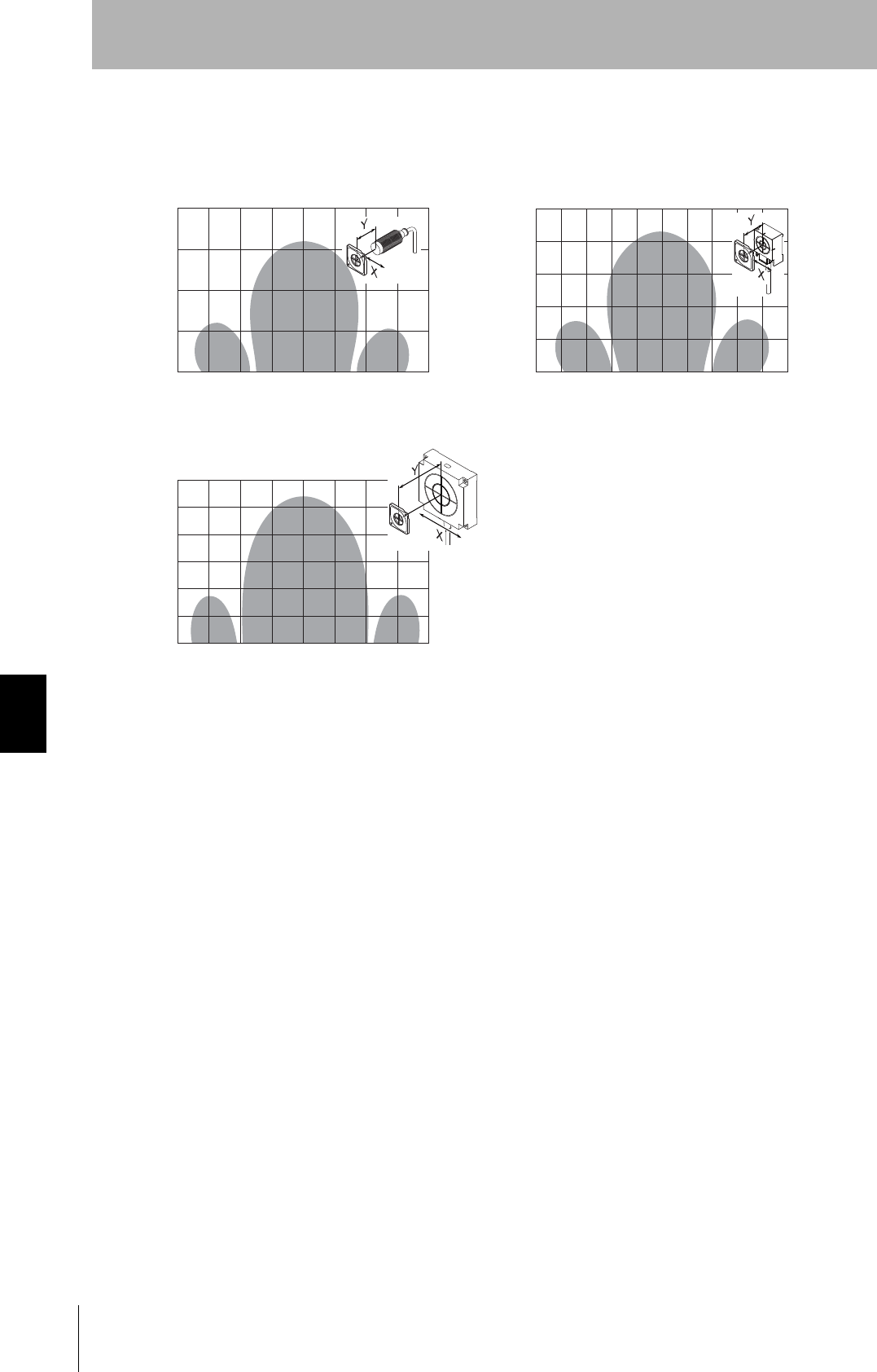
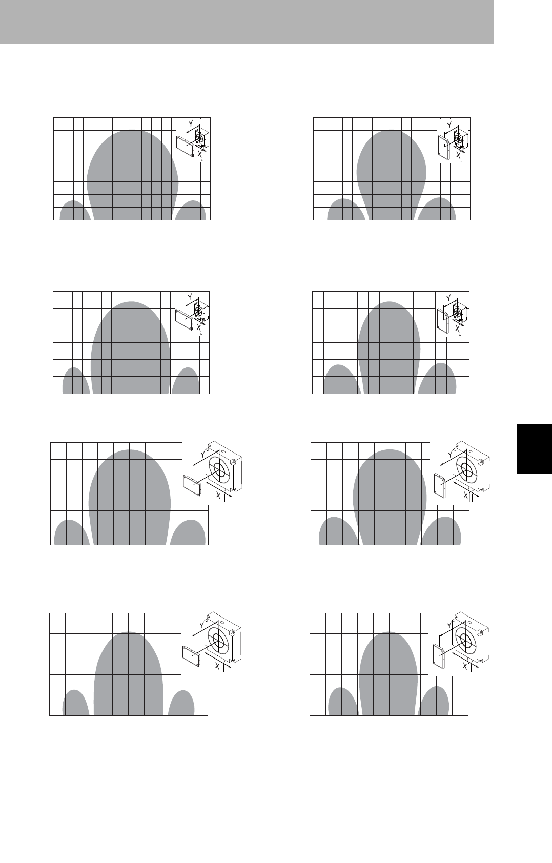
Communications Area(Reference)
V680-D1KP52MT
• V680-HS51 & V680-D1KP52MT • V680-HS51 & V680-D1KP52MT
Embedded in Metal (Steel)
• V680-HS52 & V680-D1KP52MT • V680-HS52 & V680-D1KP52MT
Embedded in Metal (Steel)
• V680-HS63 & V680-D1KP52MT
Read
Write
-15 -10 -5 0 5 10 15
0
5
10
15
X Axis (Unit: mm)
Y Axis
Read
Write
-10 -5 0 5 10
0
5
10
X Axis (Unit: mm)
Y Axis
Read
Write
-20 -15 -5 0 5 10 15
0
5
10
20
X Axis (Unit: mm)
Y Axis
Read
Write
-10 -5 0 5 10
0
5
10
X Axis (Unit: mm)
Y Axis
Read
Write
-30 -20 -10 0 10 20 30
0
10
20
30
X Axis (Unit: mm)
Y Axis
-10 20
15
137
RFID System
User's Manual
Section 7 Characteristic data
Section 7
Chemical Resistance
V680-D1KP66T
• V680-HS63 & V680-D1KP66T
• V680-HS52 & V680-D1KP66T
Read
Write
-30 -20 -10 0 10 20 30
0
20
30
X Axis (Unit: mm)
Y Axis
-40 40
40
10
Read
Write
-40 -20 0 20
0
20
30
X Axis (Unit: mm)
Y Axis
-60 40 60
40
50
60
10
• V680-HS65 & V680-D1KP66T
Read
Write
-60 -40 -20 0 20 40 60
0
40
60
X Axis (Unit: mm)
Y Axis
-100 -80 80 100
80
100
20

138
Section 7 Characteristic data
RFID System
User's Manual
Section 7
Chemical Resistance
V680-D1KP66MT
• V680-HS65 & V680-D1KP66MT
with Metal on Back Surface (Steel)
• V680-HS52 & V680-D1KP66MT
with Metal on Back Surface (Steel)
• V680-HS63 & V680-D1KP66MT
with Metal on Back Surface (Steel)
Read
Write
-30 -20 -10 0 10 20 30
0
20
30
X Axis (Unit: mm)
Y Axis
-40 40
40
10
Read
Write
-30 -20 -10 0 10 20 30
0
20
40
X Axis (Unit: mm)
Y Axis
-50 -40 40 50
50
10
Read
Write
-60 -40 -20 0 20 40 60
0
20
30
X Axis (Unit: mm)
Y Axis
-80 80
40
50
60
10
30

139
RFID System
User's Manual
Section 7 Characteristic data
Section 7
Chemical Resistance
V680-D1KP66T-SP
★Figure
㪰
㪯
㪰
㪯
㪰
㪯
• V680-HS63 & V680-D1KP66T-SP
• V680-HS52 & V680-D1KP66T-SP
Read
Write
-30 -20 -10 0 10 20 30
0
20
30
X Axis (Unit: mm)
Y Axis
-40 40
40
10
Read
Write
-40 -20 0 20
0
20
30
X Axis (Unit: mm)
Y Axis
-60 40 60
40
50
60
10
• V680-HS65 & V680-D1KP66T-SP
Read
Write
-60 -40 -20 0 20 40 60
0
40
60
X Axis (Unit: mm)
Y Axis
-100 -80 80 100
80
100
20
140
Section 7 Characteristic data
RFID System
User's Manual
Section 7
Chemical Resistance
V680-D2KF52M
• V680-HS51 & V680-D2KF52M • V680-HS51 & V680-D2KF52M
Embedded in Metal (Steel)
• V680-HS52 & V680-D2KF52M • V680-HS52 & V680-D2KF52M
Embedded in Metal (Steel)
• V680-HS63 & V680-D2KF52M
Read/Write
-15 -10 -5 0 5 10 15
0
5
10
15
X Axis (Unit: mm)
Y Axis
-10 -5 0 5 10
0
5
10
X Axis (Unit: mm)
Y Axis
-15 -10 -5 0 5 10 15
0
5
10
15
X Axis (Unit: mm)
Y Axis
-10 -5 0 5 10
0
5
10
X Axis (Unit: mm)
Y Axis
-15 -10 -5 0 5 10 15
0
5
10
15
X Axis (Unit: mm)
Y Axis
-25 -20 20 25
20
Read/Write
Read/Write Read/Write
Read/Write
141
RFID System
User's Manual
Section 7 Characteristic data
Section 7
Chemical Resistance
V680-D2KF67
• V680-HS52 & V680-D2KF67 • V680-HS63 & V680-D2KF67
• V680-HS65 & V680-D2KF67
Read/Write
-50 -40 -20 0 10 20 30
0
50
X Axis (Unit: mm)
Y Axis
-60 -40 0 20 40 60
0
20
40
X Axis (Unit: mm)
Y Axis
-100 -80 80 100
60
80
100Read/Write
-20
40
30
20
10
Read/Write
-60 -40 -20 0 20 40 60
0
60
X Axis (Unit: mm)
Y Axis
50
30
20
10
-30 -10 40 50
40
142
Section 7 Characteristic data
RFID System
User's Manual
Section 7
Chemical Resistance
V680-D2KF67M
• V680-HS52 & V680-D2KF67M
with Metal on Back Surface (Steel)
• V680-HS63 & V680-D2KF67M
with Metal on Back Surface (Steel)
• V680-HS65 & V680-D2KF67M
with Metal on Back Surface (Steel)
Read/Write
-40 -30 -20 0 10 20 30
0
X Axis (Unit: mm)
Y Axis
-60 -40 0 20 40 60
0
10
20
X Axis (Unit: mm)
Y Axis
-80 80
30
40
Read/Write
-20
40
30
20
10
Read/Write
-50 -40 -30 0 10 20 30
0
50
X Axis (Unit: mm)
Y Axis
40
30
20
10
-10 40 -20 -10 5040
50
60
143
RFID System
User's Manual
Section 7 Characteristic data
Section 7
Chemical Resistance
V680-D8KF68/-D32KF68
• V680-HS63 & V680-D8KF68/V680-D32KF68
(Horizontal-facintg ID Tag)
-60 -40 0 20 40 60
0
20
40
X Axis (Unit: mm)
Y Axis
-80 80
60
80Read/Write
-20
• V680-HS63 & V680-D8KF68/V680-D32KF68
(Vertical-facintg ID Tag)
-60 -40 0 20 40 60
0
20
40
X Axis (Unit: mm)
Y Axis
-80 80
60
80 リード/ライ ト
-20
• V680-HS63 & V680-D8KF68/V680-D32KF68
(with ATTACHMENT, V680-A81)
(Metal on back: Steel) (Horizontal-facing ID Tag)
-60 -40 0 20 40 60
0
10
20
X Axis (Unit: mm)
Y Axis
-80 80
30
40
Read/Write
-20
• V680-HS63 & V680-D8KF68/V680-D32KF68
(with ATTACHMENT, V680-A81)
(Metal on back: Steel) (Vertical-facing ID Tag)
-60 -40 0 20 40 60
0
10
20
X Axis (Unit: mm)
Y Axis
30
40
Read/Write
-20
• V680-HS65 & V680-D8KF68/V680-D32KF68
(Horizontal-facintg ID Tag)
-50 0 25 50
0
20
40
X Axis (Unit: mm)
Y Axis
-100 -75 75 100
60
80
100
Read/Write
-25
• V680-HS65 & V680-D8KF68/V680-D32KF68
(Vertical-facintg ID Tag)
Read/Write
• V680-HS65 & V680-D8KF68/V680-D32KF68
(with ATTACHMENT, V680-A81)
(Metal on back: Steel) (Horizontal-facing ID Tag)
Read/Wrete
• V680-HS65 & V680-D8KF68/V680-D32KF68
(with ATTACHMENT, V680-A81)
(Metal on back: Steel) (Vertical-facing ID Tag)
Read/Write
-125 125
120
-50 0 25 50
0
20
40
X Axis (Unit: mm)
Y Axis
-100 -75 75 100
60
80
100
-25
-125 125
120
-50 0 25 50
0
20
40
X Axis (Unit: mm)
Y Axis
-100 -75 75 100
60
80
100
-25
-125 125 -50 0 25 50
0
20
40
X Axis (Unit: mm)
Y Axis
-100 -75 75 100
60
80
100
-25
-125 125
50 50
60 60
145
RFID System
User's Manual
Section 7 Reference Data
Section 7
Chemical Resistance
Reference Data
ア ン テナ取 り 付け時の注意事項
V680-HS51
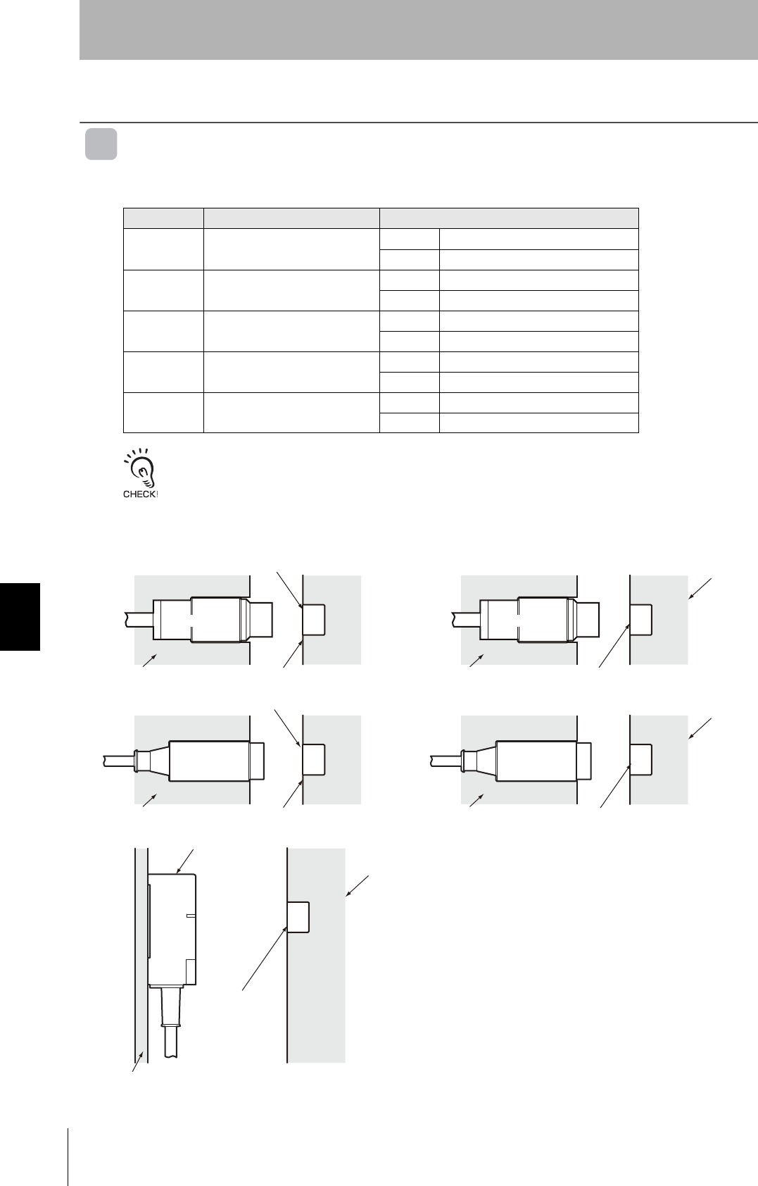
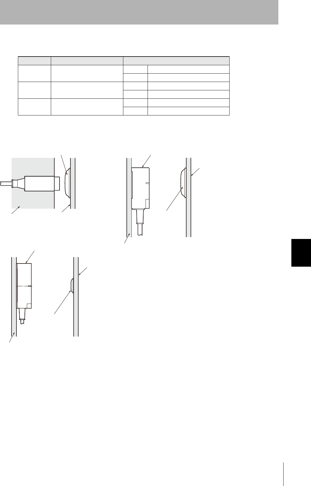
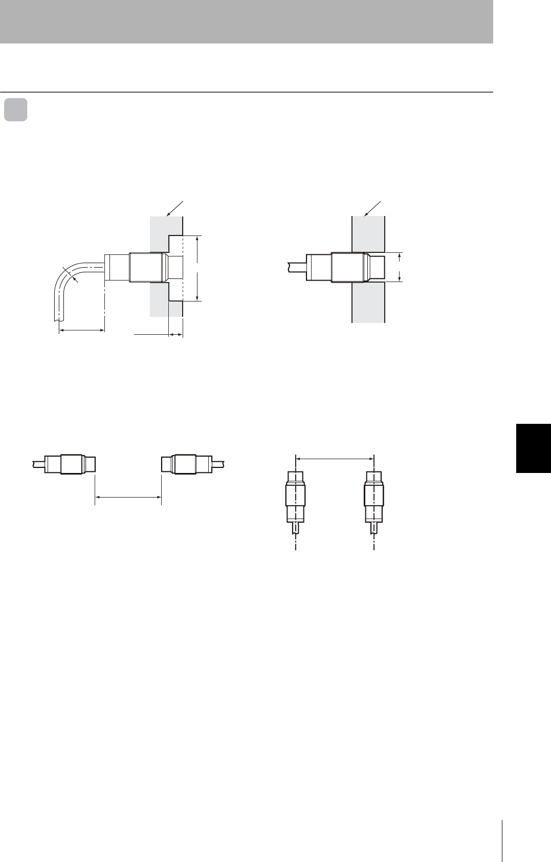
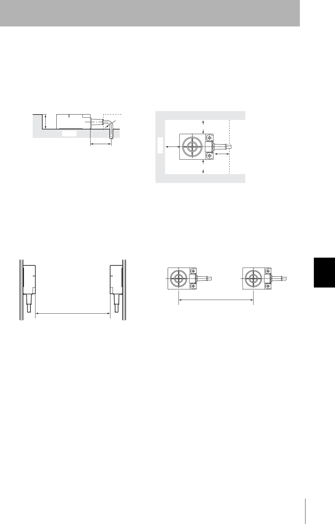
Effect of Surrounding Metals on the Antenna (Reference)
When embedding the Antenna in metal, be sure the metal does not extend beyond the tip of the
Antenna.
Mutual Interference between Antennas (Reference)
To prevent malfunctioning due to mutual interference when using more than one Antenna, leave suffi-
cient space between them as shown in the following diagrams.
R18 min.
40 mm min.
Antenna
7 mm min.
Surrounding metal
(steel)
120 (± 60) mm dia. min.
Antenna
Surrounding metal
(steel)
12 mm dia.
Communications
distance
reduced by 50%
Do not bend the cable into a curve tighter than
18 mm in radius.
If the metal around the Antenna reaches the coil surface, the
communications distance will be reduced significantly com-
pared with mounting to a non-metallic surface.
• Installing the Antennas Facing Each Other • Installing the Antennas in Parallel
80 mm min.
80 mm min.
146
Section 7 Reference Data
RFID System
User's Manual
Section 7
Chemical Resistance
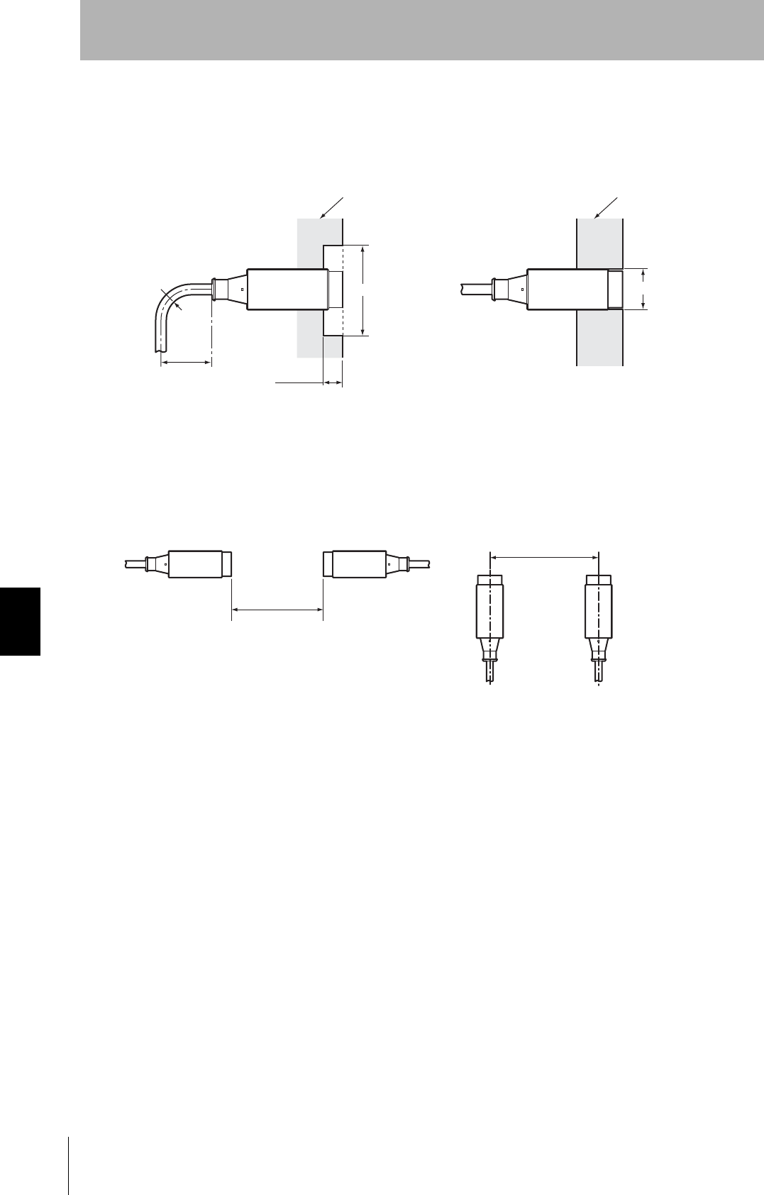
V680-HS52
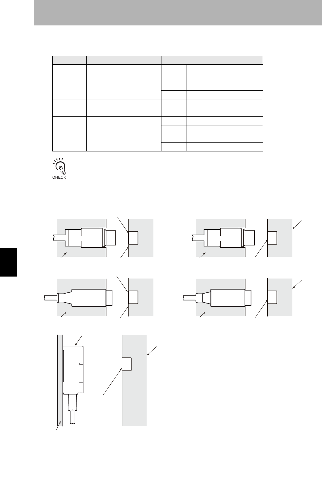
Effect of Surrounding Metals on the Antenna (Reference)
When embedding the Antenna in metal, be sure the metal does not extend beyond the tip of the
Antenna.
Mutual Interference between Antennas (Reference)
To prevent malfunctioning due to mutual interference when using more than one Antenna, leave suffi-
cient space between them as shown in the following diagrams.
R22 min.
60 mm min.
Antenna
15 mm min.
Surrounding metal
(steel)
130 (± 65) mm dia. min.
Antenna
Surrounding metal
(steel)
22 mm dia.
Communications
distance
reduced by 50%
Do not bend the cable into a curve tighter than 22
mm in radius.
If the metal around the Antenna reaches the coil surface, the
communications distance will be reduced significantly com-
pared with mounting to a non-metallic surface.
• Installing the Antennas Facing Each Other • Installing the Antennas in Parallel
120 mm min.
100 mm min.
147
RFID System
User's Manual
Section 7 Reference Data
Section 7
Chemical Resistance
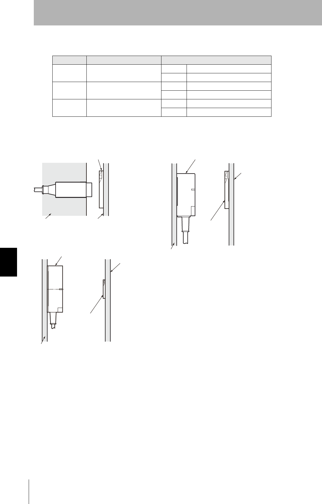
V680-HS63
Effect of Surrounding Metals on the Antenna (Reference)
In addition to surface mounting, it is also possible to embed the V680-HS63 in a metal casing to protect
it from being struck by other objects. To prevent malfunctioning, allow a space of at least 30 mm
between the Antenna and the sides of the metal casing. If the space is less than 30 mm, the read/write
distance will be greatly diminished. In addition, the height of metal casing must not exceed that of the
Antenna.
Mutual Interference between Antennas (Reference)
To prevent malfunctioning due to mutual interference when using more than one Antenna, leave suffi-
cient space between them as shown in the following diagrams.
R22 min.
60 mm min.
23mm
mim.
Metal casing
30 mm
min.
30 mm min.
30 mm min.
Note 1. Do not bend the cable into a curve
tighter than 22 mm in radius.
2. The communications distance will
be reduced significantly if the
Antenna is installed closer than 30
mm to metal surfaces.
30 mm
min.
Metal casing
• Installing the Antennas Facing Each Other • Installing the Antennas in Parallel
430 mm min.
270 mm min.

148
Section 7 Reference Data
RFID System
User's Manual
Section 7
Chemical Resistance
V680-HS65
Effect of Surrounding Metals on the Antenna (Reference)
In addition to surface mounting, it is also possible to embed the V680-HS65 in a metal casing to protect
it from being struck by other objects. To prevent malfunctioning, allow a space of at least 100 mm
between the Antenna and the sides of the metal casing. If the space is less than 100 mm, the read/
write distance will be greatly diminished. In addition, the height of metal casing must not exceed that of
the Antenna.
Mutual Interference between Antennas (Reference)
To prevent malfunctioning due to mutual interference when using more than one Antenna, leave suffi-
cient space between them as shown in the following diagrams.
R22 min.
60mm min.
30mm
min.
Metal casing
100mm
min.
100mm min.
100mm min.
100mm
min.
Note 1. Do not bend the cable into a curve
tighter than 22 mm in radius.
2. The communications distance will
be reduced significantly if the
Antenna is installed closer than 100
mm to metal surfaces.
Metal casing
• Installing the Antennas Facing Each Other • Installing the Antennas in Parallel
700 mm min.
400 mm min.
149
RFID System
User's Manual
Section 7 Reference Data
Section 7
Chemical Resistance
ID タ グ取 り 付け時の注意事項
V680-D1KP52MT
Differences in Surrounding Metals (Reference)
Communications distances are affected by the type of metal in back of or surrounding the Tag, as
shown in the following table.
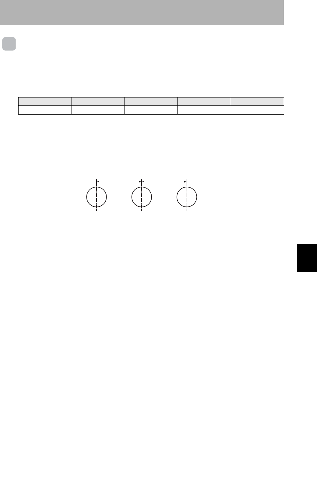
Mutual Interference with Tags (Reference)
Provide the mounting distances indicated below to prevent malfunctions due to mutual interference
when using more than one Tag.
鉄SUS 黄銅 アルミ ニウム
形V680-D1KP52MT 100% 85~90% 80~85% 80~85%
注. 周囲/背面金属が鉄の場合を100%と し ています。
25mm min. 25mm min.
150
Section 7 Reference Data
RFID System
User's Manual
Section 7
Chemical Resistance
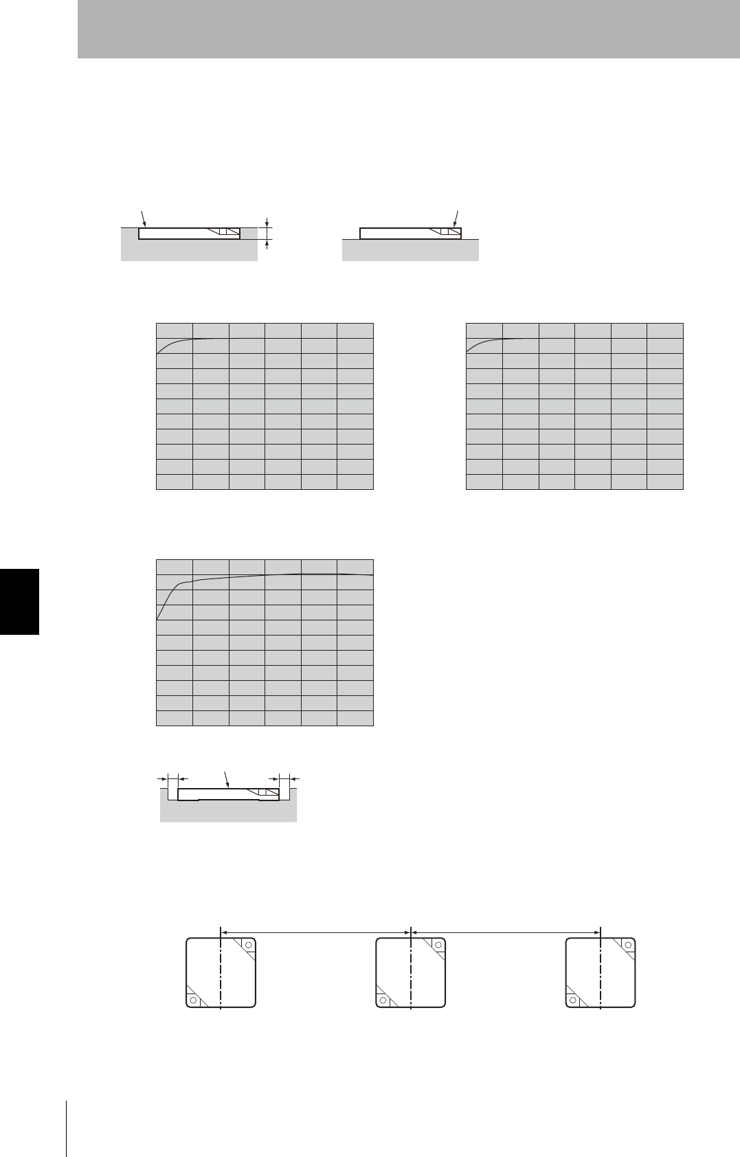
V680-D1KP66MT
Effect of Metal behind Tags (Reference)
The V680-D1KP66MT can be surface-mounted or it can be embedded in metal. If it is embedded in
metal, the height of the metal casing must not exceed that of the Tag.
Mutual Interference with Tags (Reference)
Provide the mounting distances indicated below to prevent malfunctions due to mutual interference
when using more than one Tag.
ID Tag
3.5mm min.
Metal
Embedded
ID Tag
Metal
Surface-mounted
金属
ID タ グ
xx
• V680-HS52 &V680-D1KP66MT
10 20 30 40 50 (mm)
0
50
70
Distance to metal (x)
60
40
30
20
10
90
(%)
100
80
The communications distance without
metal is 100%
• V680-HS63 &V680-D1KP66MT
10 20 30 40 50 (mm)
0
50
70
Distance to metal (x)
60
40
30
20
10
90
(%)
100
80
The communications distance without
metal is 100%
• V680-HS65 &V680-D1KP66MT
10 20 30 40 50 (mm)
0
50
70
Distance to metal (x)
60
40
30
20
10
90
(%)
100
80
The communications distance without
metal is 100%
60
100mm min. 100mm min.
151
RFID System
User's Manual
Section 7 Reference Data
Section 7
Chemical Resistance
V680-D2KF52M
Differences in Surrounding Metals (Reference)
Communications distances are affected by the type of metal in back of or surrounding the Tag, as
shown in the following table.
The values for steel are set to 100%
Mutual Interference with Tags (Reference)
Provide the mounting distances indicated below to prevent malfunctions due to mutual interference
when using more than one Tag.
Steel SUS Brass Aluminum
V680-D2KF52M 100% 80% to 85% 80% to 85% 75% to 80%
25mm min. 25mm min.
152
Section 7 Reference Data
RFID System
User's Manual
Section 7
Chemical Resistance
V680-D2KF67M
Effect of Surrounding Metals (Reference)
The V680-D2KF67M can be surface-mounted or it can be embedded in metal. If it is embedded in
metal, the height of the metal casing must not exceed that of the Tag.
Mutual Interference with Tag (Reference)
To prevent malfunctioning due to mutual interference when using more than one Tag,
leave sufficient space between them as shown in the following diagram.
ID Tag
4.5mm min.
Metal
Embedded ID Tag
Metal
Surface-mounted
• V680-HS52 &V680-D2KF67M
10 20 30 40 50 (mm)
0
50
70
Distance to metal (x)
60
40
30
20
10
90
(%)
100
80
The communications distance without
metal is 100%
• V680-HS63 & V680-D2KF67M
10 20 30 40 50 (mm)
0
50
70
Distance to metal (x)
60
40
30
20
10
90
(%)
100
80
The communications distance without
metal is 100%
• V680-HS65 & V680-D2KF67M
10 20 30 40 50 (mm)
0
50
70
Distance to metal (x)
60
40
30
20
10
90
(%)
100
80
The communications distance without
metal is 100%
ID Tag X
X
120mm min. 120mm min.
153
RFID System
User's Manual
Section 7 Reference Data
Section 7
Chemical Resistance
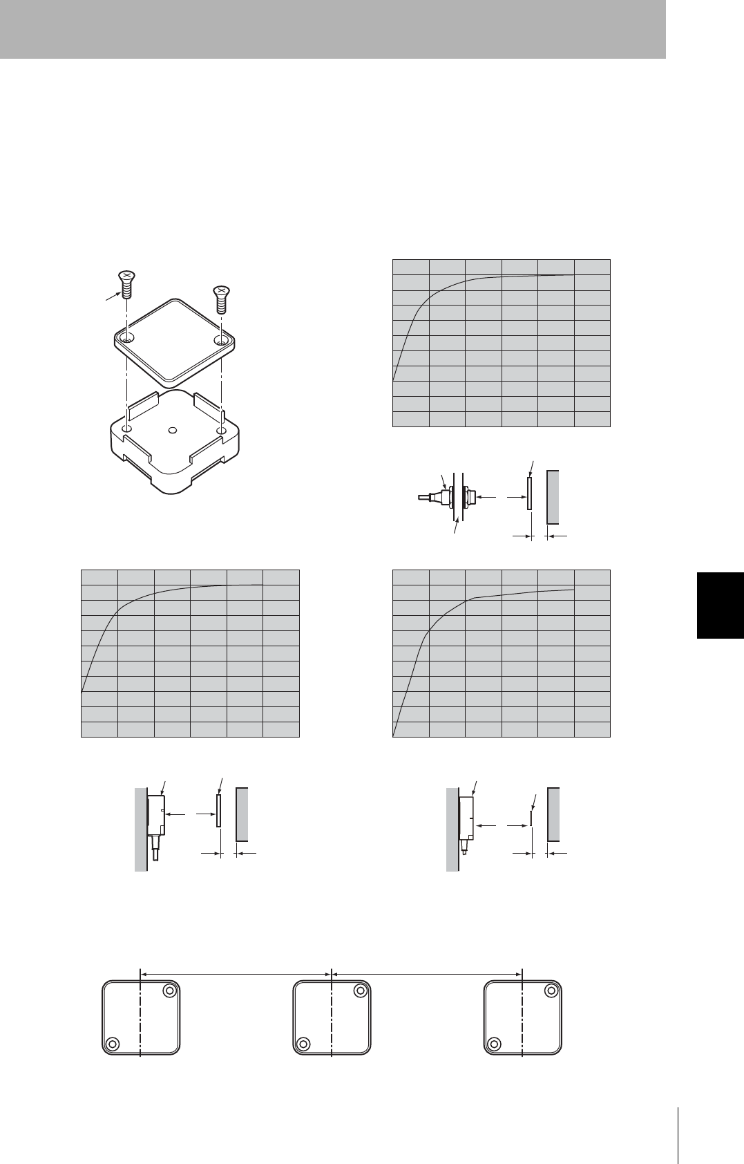
V680-D1KP66T
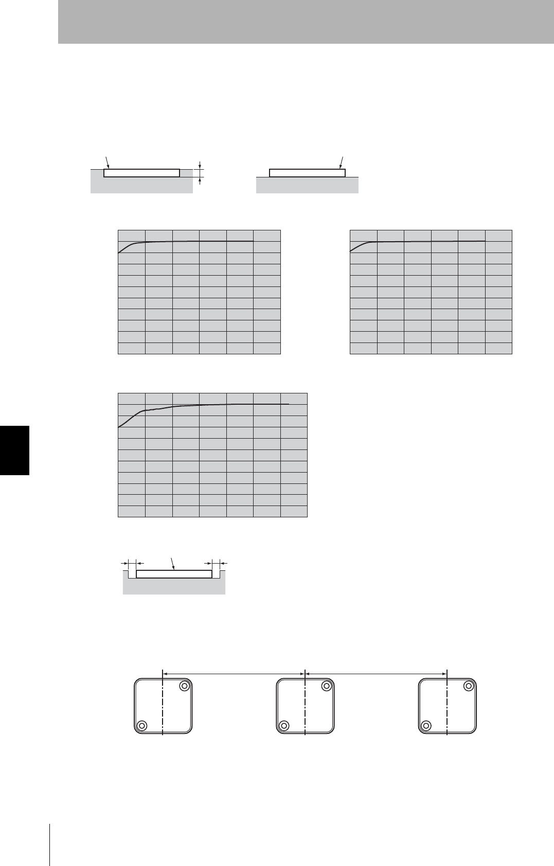
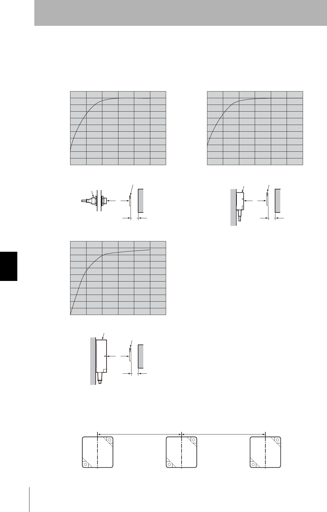
Effect of Metal behind Tags (Reference)
The V680-D1KP66T communications distance is reduced if there is any metal material behind the Tag.
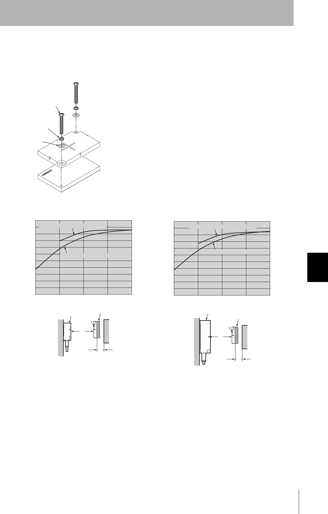
If the Tag is to be mounted to metal, then either use a V600-A86 Attachment (sold separately) or insert
a non-metal spacer (such as plastic or resin). The relationship between the distance from the Tag to
the metal surface and the communications distance is shown below.
The Attachment is 10 mm thick, and more than one Attachment can be stacked.
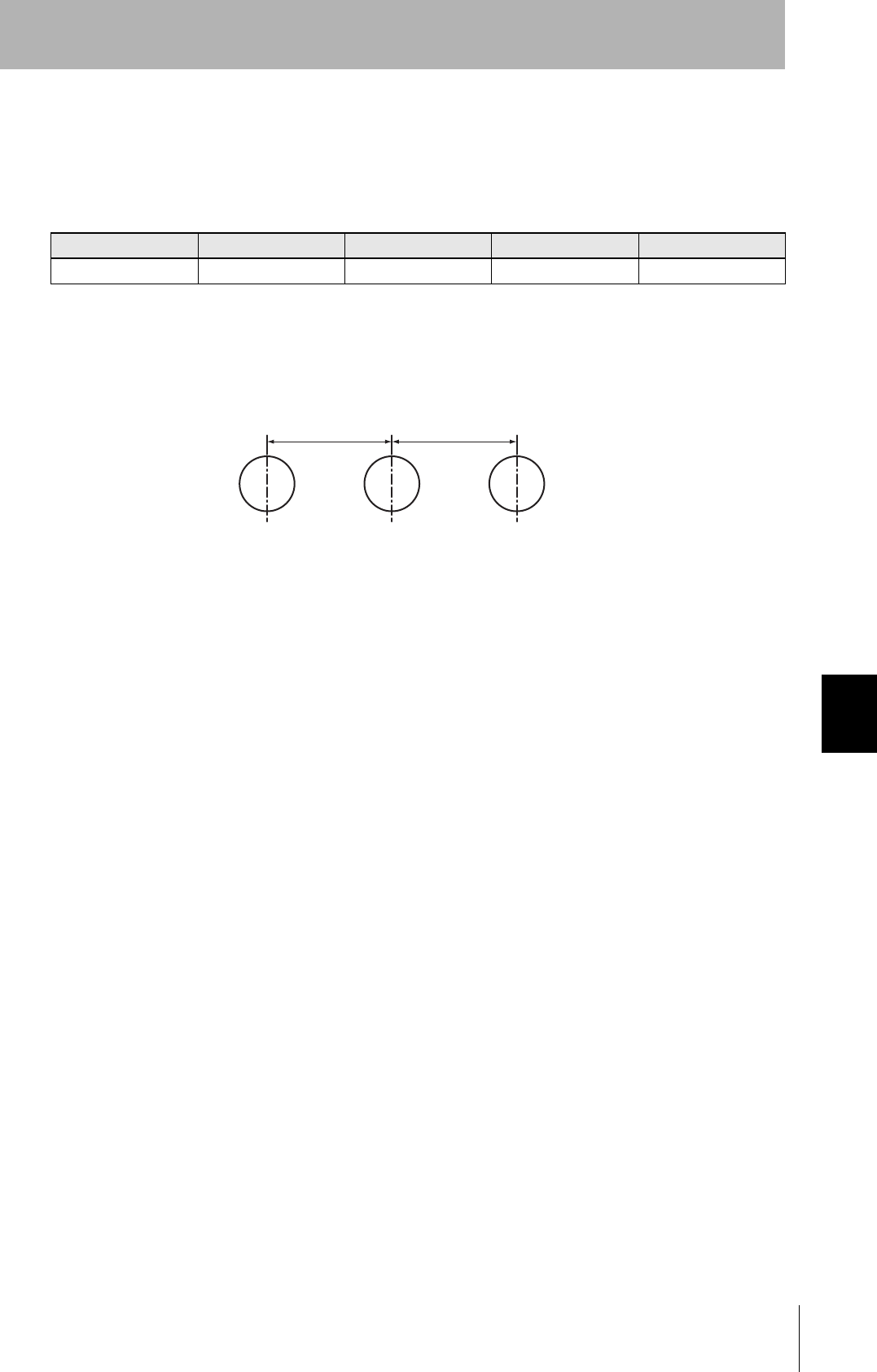
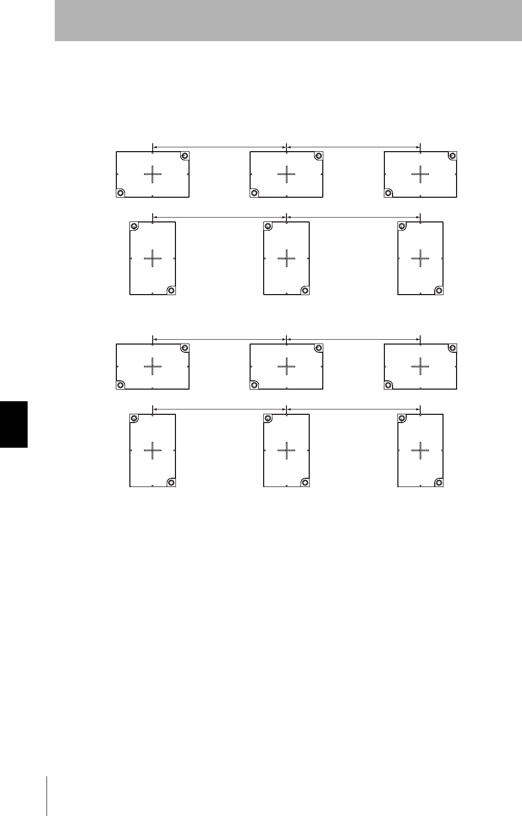
Mutual Interference with Tag (Reference)
To prevent malfunctioning due to mutual interference when using more than one Tag, leave sufficient
space between them as shown in the following diagram.
M3 countersunk screw
V600-A86 Attachment Installation
Install so that the mounting holes are aligned.
• V680-HS52 &V680-D1KP66T
10 20 30 40 50 (mm)
0
50
70
Distance to metal (x)
60
40
30
20
10
90
(%)
100
80
The communications distance without
metal is 100%
ID Tag
Metal on back
Antenna
Communica-
tions
distance
Y
X
Metal
• V680-HS63 &V680-D1KP66T
10 20 30 40 50 (mm)
0
50
70
Distance to metal (x)
60
40
30
20
10
90
(%)
100
80
The communications distance without
metal is 100%
• V680-HS65 &V680-D1KP66T
10 20 30 40 50 (mm)
0
50
70
Distance to metal (x)
60
40
30
20
10
90
(%)
100
80
The communications distance without
metal is 100%
Antenna ID Tag
Metal on back
Metal Y
XCommunica-
tions
distance
Antenna ID Tag Metal on back
Metal Y
X
Communica-
tions
distance
100mm min. 100mm min.
154
Section 7 Reference Data
RFID System
User's Manual
Section 7
Chemical Resistance
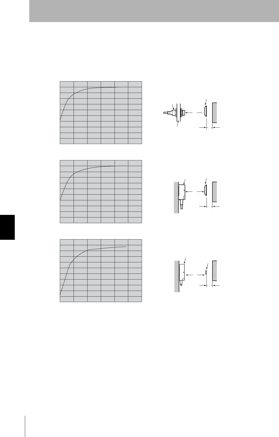
V680-D1KP66T-SP
Effect of Metal behind Tags (Reference)
Mounting ID Tags to metal workpieces or palettes will affect the communications capabilities. Place non-metal-
lic parts (e.g., plastic or resin) between the metallic parts by referring to the following relationship between the
distance between the ID Tag and the metallic body versus the communications distance.
• V680-HS52 &V680-D1KP66T-SP
10 20 30 40 50 (mm)
0
50
70
Distance to metal (x)
60
40
30
20
10
90
(%)
100
80
The communications distance without
metal is 100%
• V680-HS63 &V680-D1KP66T-SP
10 20 30 40 50 (mm)
0
50
70
Distance to metal (x)
60
40
30
20
10
90
(%)
100
80
The communications distance without
metal is 100%
• V680-HS65 &V680-D1KP66T-SP
10 20 30 40 50 (mm)
0
50
70
Distance to metal (x)
60
40
30
20
10
90
(%)
100
80
The communications distance without
metal is 100%
ID Tag
Metal on back
Antenna
Y
X
Metal
Communica-
tions
distance
Antenna ID Tag
Metal on back
Metal Y
X
Communica-
tions
distance
Y
X
Communica-
tions
distance
Metal
Antenna ID Tag
Metal on back
155
RFID System
User's Manual
Section 7 Reference Data
Section 7
Chemical Resistance
Mutual Interference with Tag (Reference)
To prevent malfunctioning due to mutual interference when using more than one Tag, leave sufficient
space between them as shown in the following diagram.
100mm min. 100mm min.
100mm min. 100mm min.
156
Section 7 Reference Data
RFID System
User's Manual
Section 7
Chemical Resistance
V680-D2KF67
Effect of Metal behind Tags (Reference)
The V680-D2KF67 communications distance is reduced if there is any metal material behind the Tag.
Mutual Interference with Tag (Reference)
To prevent malfunctioning due to mutual interference when using more than one Tag, leave sufficient
space between them as shown in the following diagram.
• V680-HS52 &V680-D2KF67
10 20 30 40 50 (mm)
0
50
70
Distance to metal (x)
60
40
30
20
10
90
(%)
100
80
The communications distance without
metal is 100%
• V680-HS63 &V680-D2KF67
10 20 30 40 50 (mm)
0
50
70
Distance to metal (x)
60
40
30
20
10
90
(%)
100
80
The communications distance without
metal is 100%
• V680-HS65 &V680-D2KF67
10 20 30 40 50 (mm)
0
50
70
Distance to metal (x)
60
40
30
20
10
90
(%)
100
80
The communications distance without
metal is 100%
ID Tag
Metal on back
Antenna
Communica-
tions
distance
Y
X
ID Tag
Metal on back
Antenna
Communica-
tions
distance
Y
X
ID Tag
Metal on back
Antenna
Communica-
tions
distance
Y
X
Metal
200mm min. 200mm min.
157
RFID System
User's Manual
Section 7 Reference Data
Section 7
Chemical Resistance
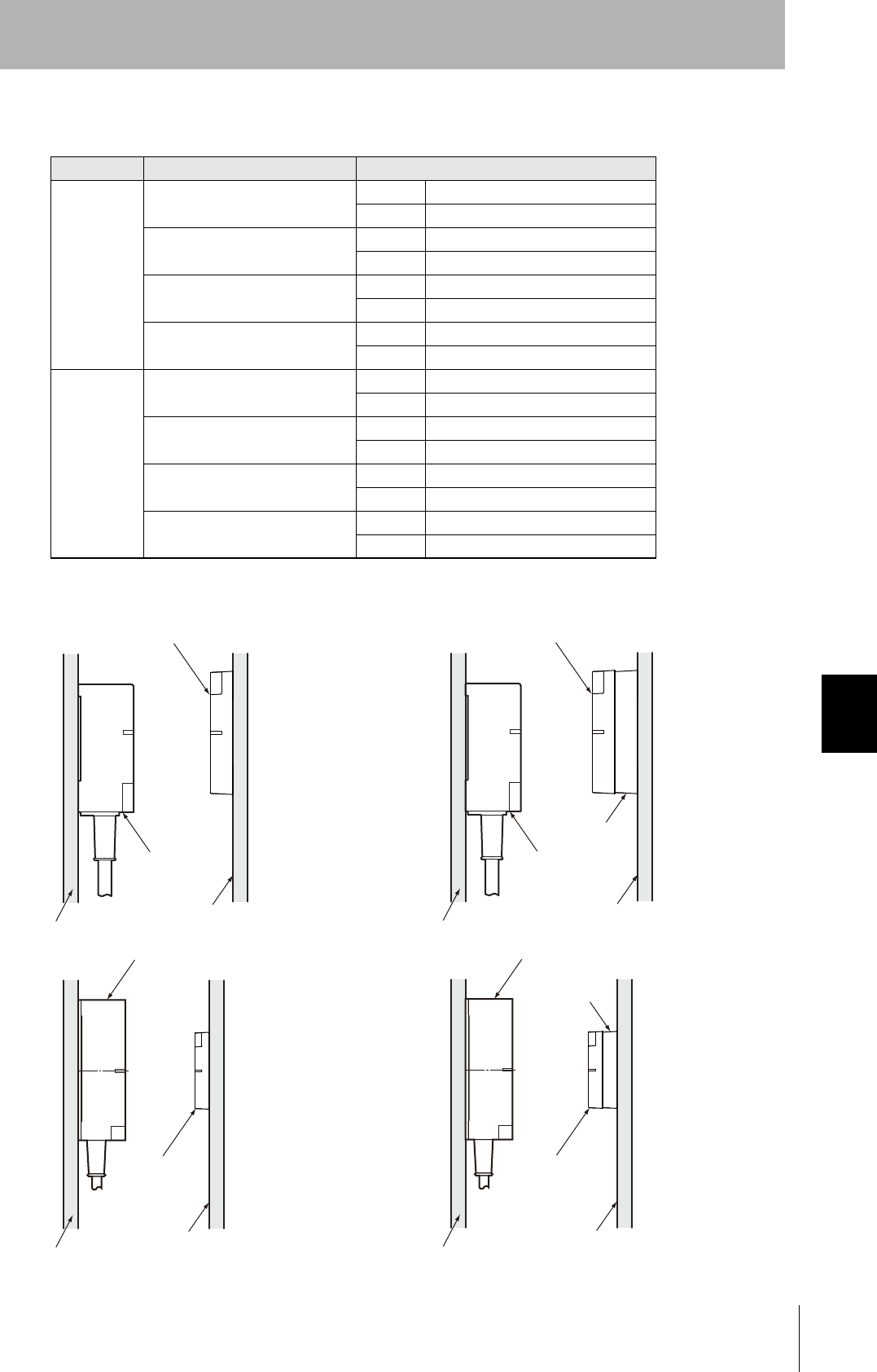
V680-D8KF68/-D32KF68
Effect of Metal behind Tags (Reference)
The transmission distance will be reduced if there is metal in back of
a Tag. When mounting on a metal surface, use the special
Attachment (V680-A81) of another sales or insert a non-metallic
spacer (e.g., plastic, wood, etc.).
The following diagrams show the relationship between the distance
between a Tag and metal surface and the transmission distance. The
Attachment is 10 mm thick.
• Special Attachment (V680-A81) Installation Direction
M4 screw
Spring washer
Flat washer
• V680-HS63 &V680-D8KF68/-D32KF68
10 20 30 40
(mm)
0
50
70
Distance to metal (x)
60
40
30
20
10
90
(%)
100
80
The communications distance without
metal is 100%
Antenna
When Attachment (V680-A81) is not used
When Attachment (V680-A81) is used
Atachment
Metal on back
Metal
Communica-
tions
distance
Y
X
ID Tag
• V680-HS63 &V680-D8KF68/-D32KF68
10 20 30 40
(mm)
0
50
70
Distance to metal (x)
60
40
30
20
10
90
(%)
100
80
The communications distance without
metal is 100%
When Attachment (V680-A81) is not used
When Attachment (V680-A81) is used
Atachment
Antenna
Metal
Metal on back
Y
X
Communica-
tions
distance
ID Tag
158
Section 7 Reference Data
RFID System
User's Manual
Section 7
Chemical Resistance
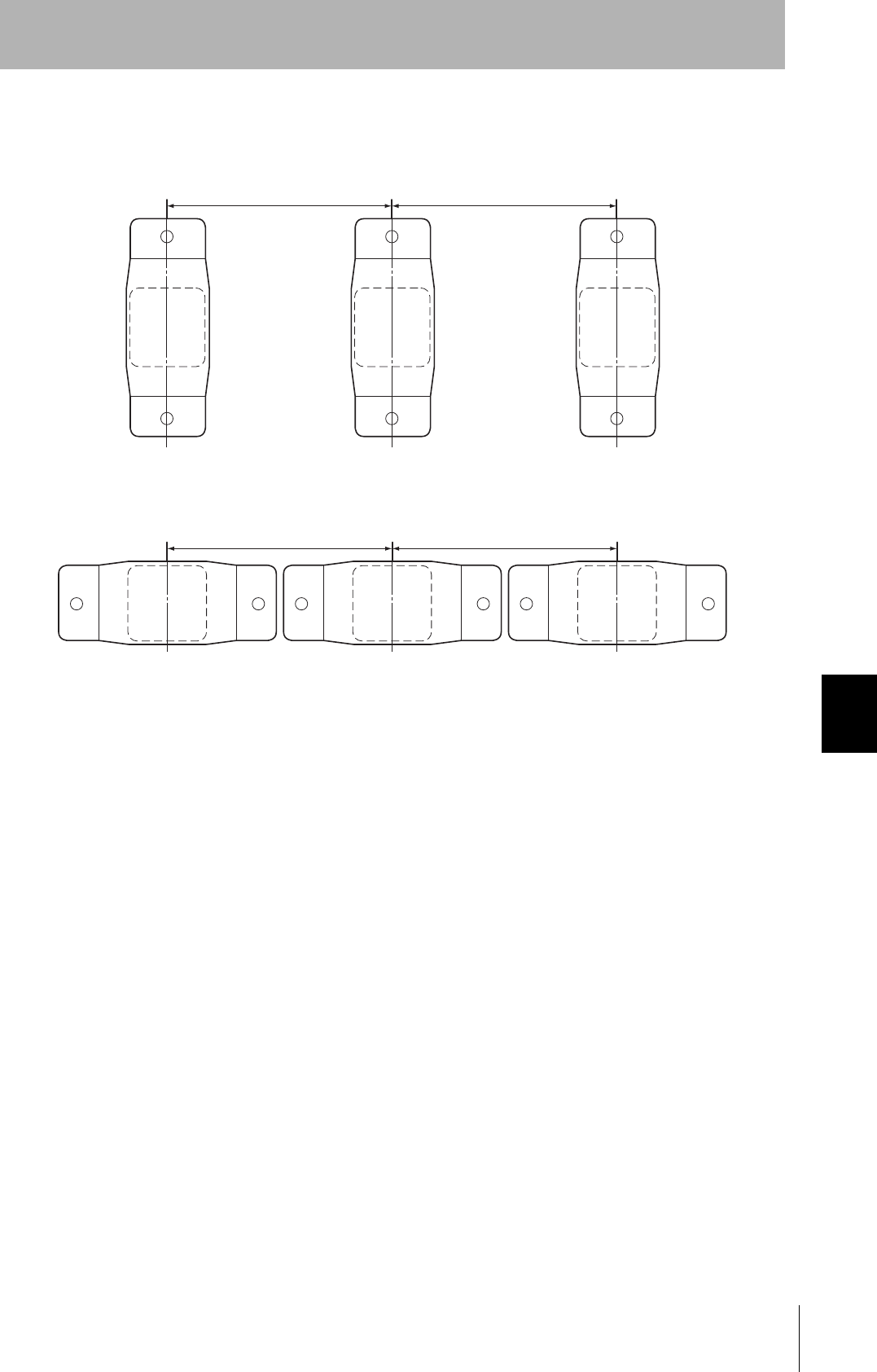
Mutual Interference with Tags (Reference)
To prevent malfunctioning due to mutual interference when using more than one Tag, leave sufficient
space between them as shown in the following diagram.
When V680-HS63, V680-HS52 are Used
When V680-HS65 is Used
120mm min. 120mm min.
120mm min. 120mm min.
150mm min. 150mm min.
150mm min. 150mm min.

159
RFID System
User's Manual
Section 7 Reference Data
Section 7
Chemical Resistance
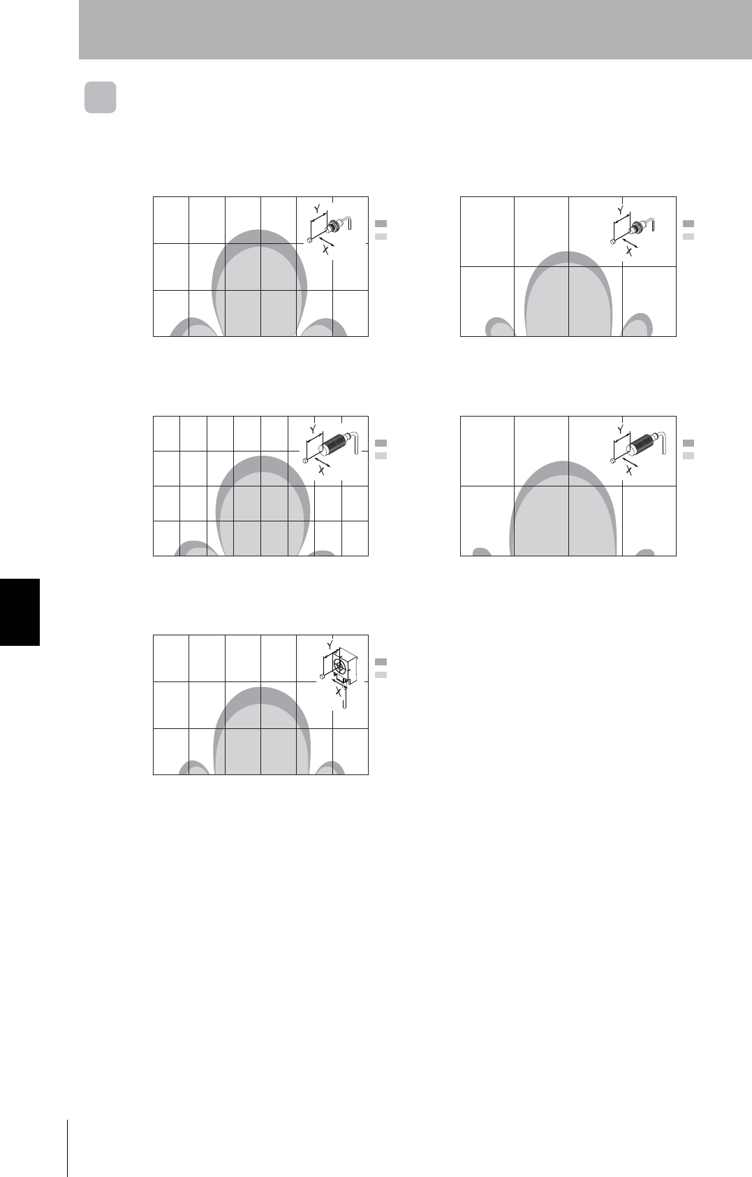
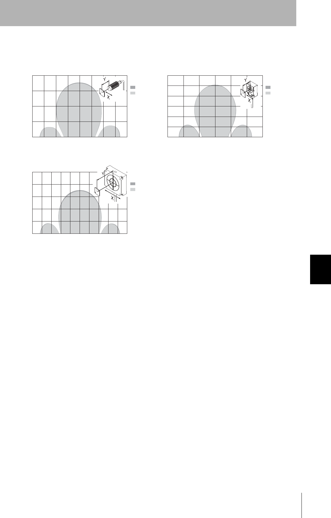
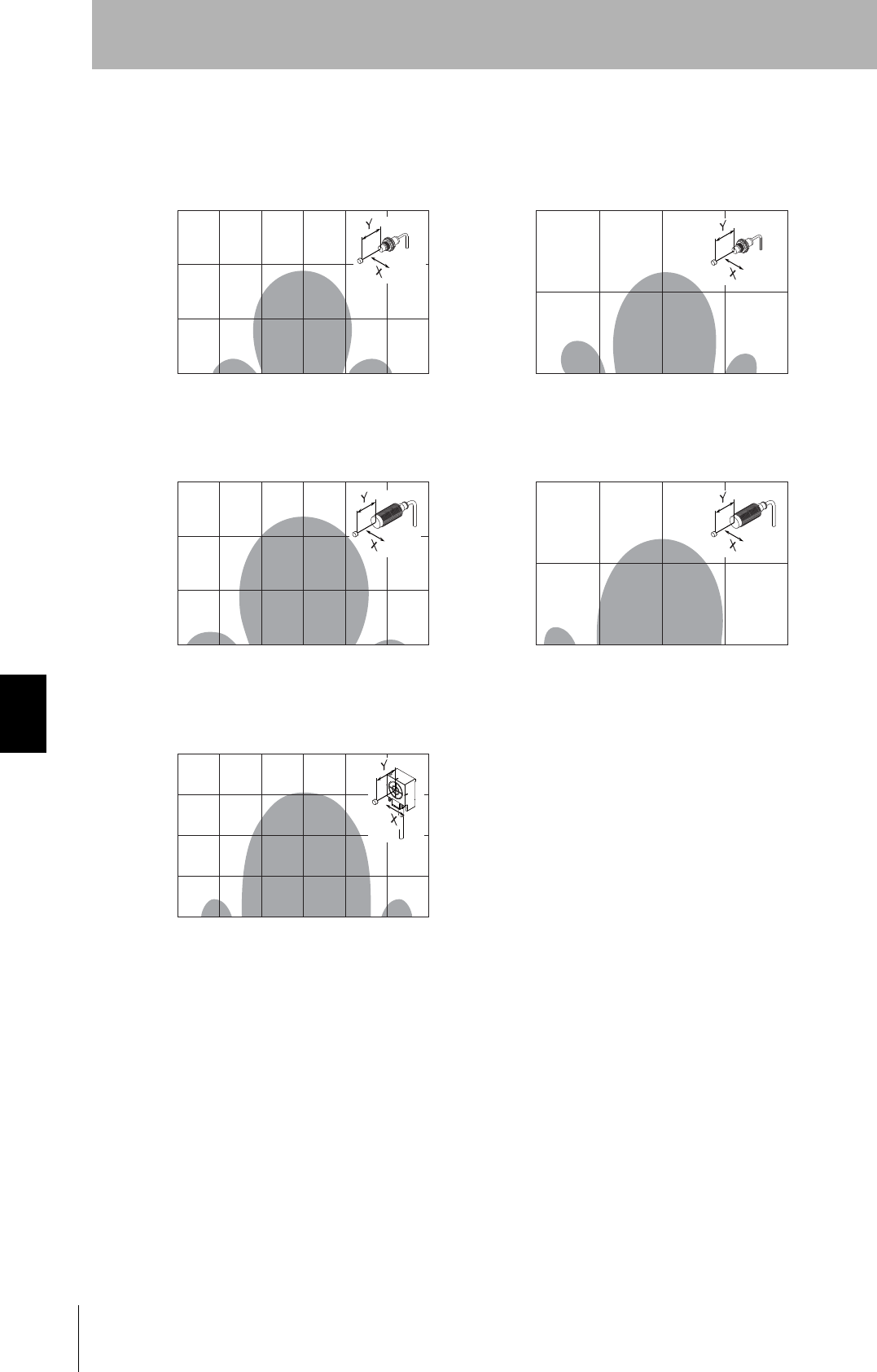
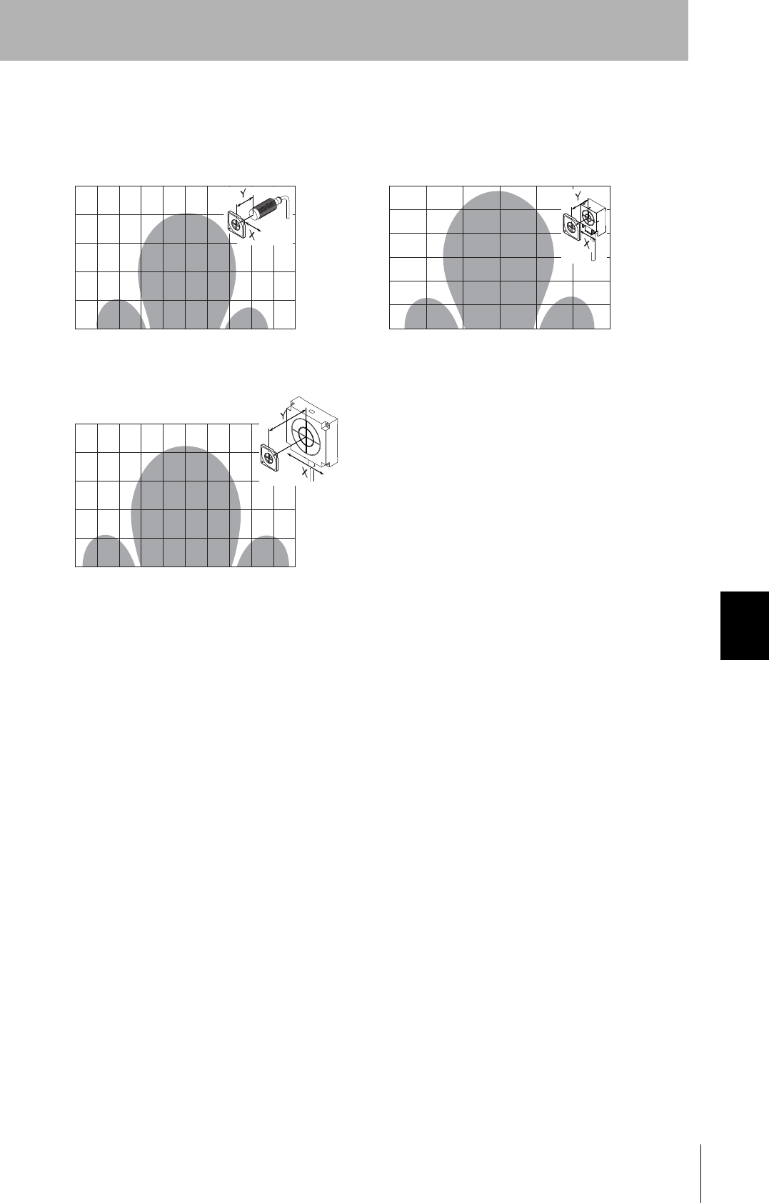
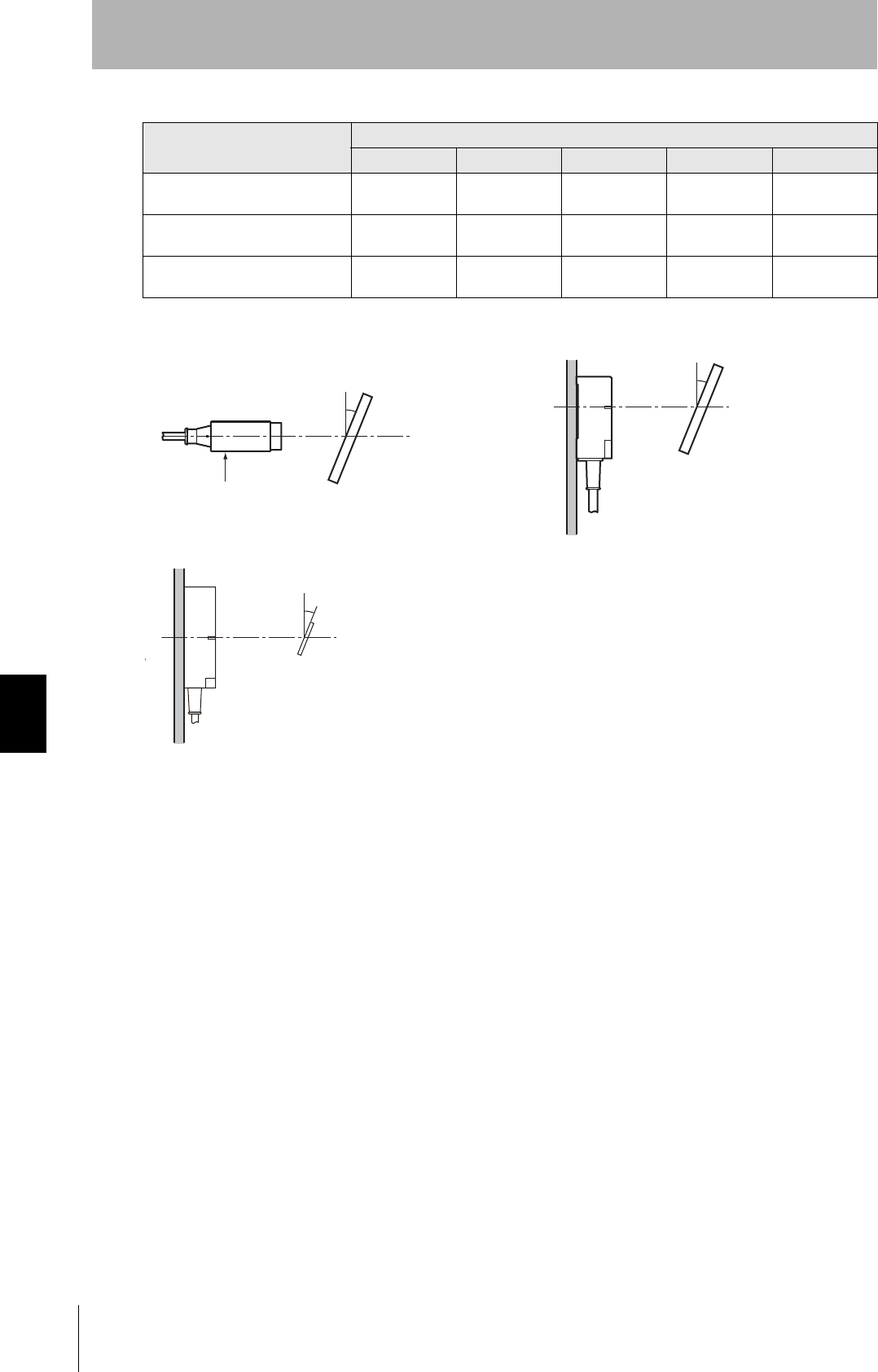
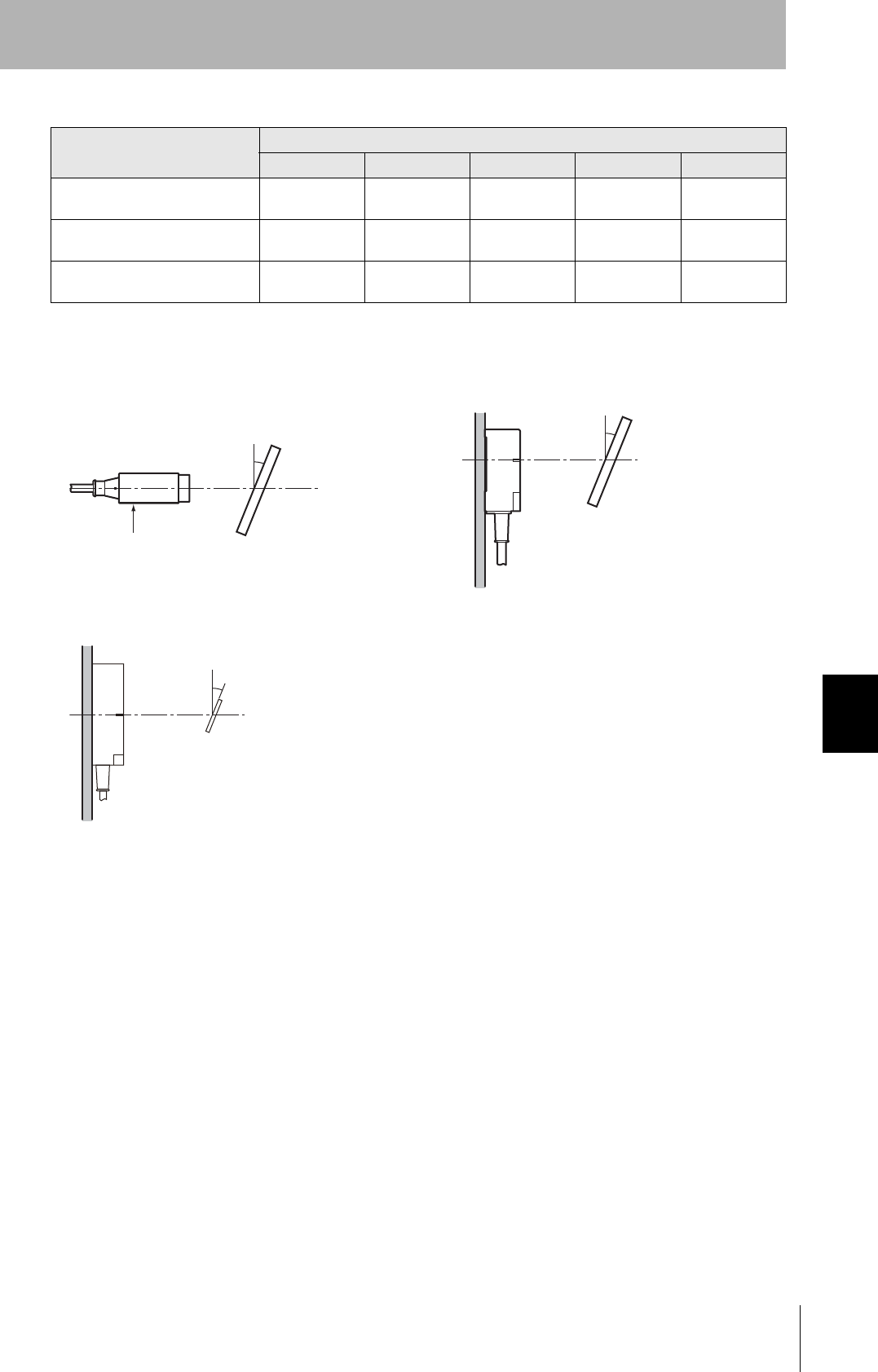
Infuence of Angle (Refernce)
Install Antennas and Tags as close to parallel to each other as possible. Communications are possible
even when an Antenna and a Tag are mounted at an angle, but the communications distance will be
shortened. The relation between the angle and the communications distance is shown below.
Percentage Drop in Communications Distance According to Angle of V680-D1KP52MT
Tag angle (θ°)
010 20 30 40
V680-HS51 and V680-D1KP52MT 0% -1% -5% -10% -15%
V680-HS51 and V680-D1KP52MT
(Metal: Steel) 0% 0% 0% -4% -28%
V680-HS52 and V680-D1KP52MT 0% 0% 0% -2% -6%
V680-HS52 and V680-D1KP52MT
(Metal: Steel) 0% -6% -13% -25% -
V680-HS63 and V680-D1KP52MT 0% -2% -5% -9% -14%
-: The measurement is no possible because the Tag comes in contact with the Antenna.
• V680-HS51 & V680-D1KP52MT • V680-HS51 & V680-D1KP52MT
(Metal: Steel)
• V680-HS52 & V680-D1KP52MT • V680-HS52 & V680-D1KP52MT
(Metal: Steel)
●形V680-HS63 & 形V680-D1KP52MT
Antenna Nuts ID Tag
Steel
Toothed washer Non-metallic
material
θ
Antenna Nuts ID Tag
Steel
Toothed washer θ
Steel
Antenna
ID Tag
θNon-metallic
material
Antenna
ID Tag
Steel
θ
Antenna
ID Tag
θNon-metallic
material
Steel
160
Section 7 Reference Data
RFID System
User's Manual
Section 7
Chemical Resistance
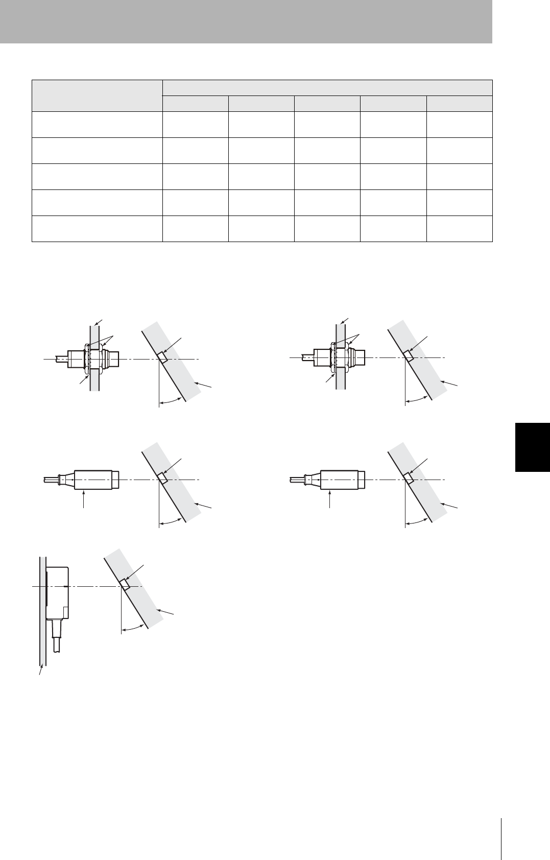
Percentage Drop in Communications Distance According to Angle of V680-D1KP66T
Tag angle (θ°)
010 20 30 40
V680-HS52 and V680-D1KP66T 0% -1% -2% -4% -7%
V680-HS63 and V680-D1KP66T 0% -2% -3% -5% -9%
V680-HS65 and V680-D1KP66T 0% -1% -3% -6% -11%
• V680-HS52 & V680-D1KP66T • V680-HS63 & V680-D1KP66T
• V680-HS65 & V680-D1KP66T
Antenna ID Tag
θ
Antenna
ID Tag
Non-metallic material
θ
Metal
Antenna
ID Tag
θ
161
RFID System
User's Manual
Section 7 Reference Data
Section 7
Chemical Resistance
Percentage Drop in Communications Distance According to Angle of V680-D1KP66MT
Tag angle (θ°)
010 20 30 40
V680-HS52 and V680-D1KP66MT
(Metal: Steel) 0% -1% -2% -5% -9%
V680-HS63 and V680-D1KP66MT
(Metal: Steel) 0% -1% -4% -7% -13%
V680-HS65 and V680-D1KP66MT
(Metal: Steel) 0% -1% -6% -15% -
-: The measurement is no possible because the Tag comes in contact with the Antenna.
• V680-HS52 & V680-D1KP66MT
(Metal: Steel)
• V680-HS63 & V680-D1KP66MT
(Metal: Steel)
• V680-HS65 & V680-D1KP66MT
(Metal: Steel)
ID Tag
θ
Antenna
Antenna
ID Tag
Non-metallic material
θ
Antenna
ID Tag
θ
Metal

162
Section 7 Reference Data
RFID System
User's Manual
Section 7
Chemical Resistance
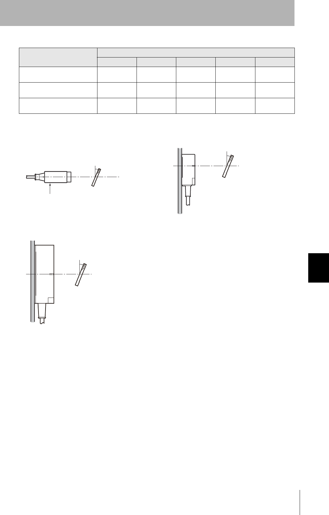
Percentage Drop in Communications Distance According to Angle of V680-D1KP66T-SP
Tag angle (θ°)
010 20 30 40
V680-HS52 and V680-D1KP66T-SP 0% -1% -2% -4% -7%
V680-HS63 and V680-D1KP66T-SP 0% -2% -3% -5% -9%
V680-HS65 and V680-D1KP66T-SP 0% -1% -3% -6% -11%
• V680-HS52 & V680-D1KP66T-SP • V680-HS63 & V680-D1KP66T-SP
• V680-HS65 & V680-D1KP66T-SP
ID Tag
θ
Antenna
Antenna
ID Tag
Non-metallic material
θ
Antenna
ID Tag
θ
Metal
163
RFID System
User's Manual
Section 7 Reference Data
Section 7
Chemical Resistance
Percentage Drop in Communications Distance According to Angle of V680-D2KF52M
Tag angle (θ°)
010 20 30 40
V680-HS51 and V680-D2KF52M 0% -2% -6% -12% -22%
V680-HS51 and V680-D2KF52M
(Metal: Steel) 0% 0% 0% -7% -30%
V680-HS52 and V680-D2KF52M 0% 0% 0% -2% -5%
V680-HS52 and V680-D2KF52M
(Metal: Steel) 0% -2% -7% - -
V680-HS63 and V680-D2KF52M 0% 0% -1% -4% -9%
-: The measurement is no possible because the Tag comes in contact with the Antenna.
• V680-HS51 & V680-D2KF52M • V680-HS51 & V680-D2KF52M
(Metal: Steel)
• V680-HS52 & V680-D2KF52M • V680-HS52 & V680-D2KF52M
(Metal: Steel)
• V680-HS63 & V680-D2KF52M
ID Tag
θ
Antenna
Nuts
Steel
Toothed washer Non-metallic
material
ID Tag
θ
Antenna
Nuts
Steel
Toothed washer Non-metallic
material
ID Tag
θ
Antenna Non-metallic
material
ID Tag
Antenna Steel
θ
ID Tag
θ
Non-metallic
material
Antenna
Steel

164
Section 7 Reference Data
RFID System
User's Manual
Section 7
Chemical Resistance
Percentage Drop in Communications Distance According to Angle of V680-D2KF67
Tag angle (θ°)
010 20 30 40
V680-HS52 and V680-D2KF67 0% -0% 0% -1% -2%
V680-HS63 and V680-D2KF67 0% -1% -2% -3% -6%
V680-HS65 and V680-D2KF67 0% -1% -3% -7% -11%
• V680-HS52 & V680-D2KF67 • V680-HS63 & V680-D2KF67
• V680-HS65 & V680-D2KF67
ID Tag
θ
Antenna
Antenna
ID Tag
Non-metallic material
θ
ID Tag
θ
Metal
Antenna
165
RFID System
User's Manual
Section 7 Reference Data
Section 7
Chemical Resistance
Percentage Drop in Communications Distance According to Angle of V680-D2KF67M
Tag angle (θ°)
010 20 30 40
V680-HS52 and V680-D2FKP67M
(Metal: Steel) 0% -1% -2% -4% -6%
V680-HS63 and V680-D2FKP67M
(Metal: Steel) 0% -2% -5% -8% -14%
V680-HS65 and V680-D2FKP67M
(Metal: Steel) 0% -2% -7% -16% -31%
• V680-HS52 & V680-D2KF67M
(Metal: Steel)
• V680-HS63 & V680-D2KF67M
(Metal: Steel)
• V680-HS65 & V680-D2KF67M
(Metal: Steel)
ID Tag
θ
Antenna
Antenna
ID Tag
Non-metallic material
θ
ID Tag
θ
Metal
Antenna
166
Section 7 Reference Data
RFID System
User's Manual
Section 7
Chemical Resistance
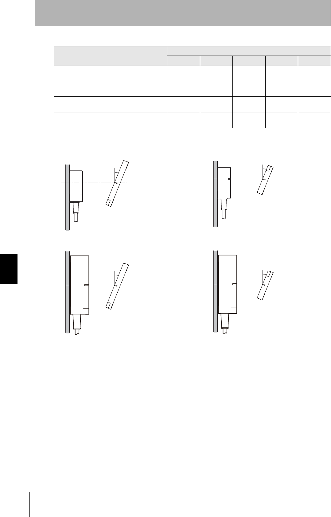
Percentage Drop in Communications Distance According to Angle of V680-
D8KF68, V680-D32KF68
Tag angle (θ°)
010 20 30 40
V680-HS63 and V680-D8KF68 or V680-D32KF68
(Horizontal-facing ID Tag) 0% 0% 0% 0% 0%
V680-HS63 and V680-D8KF68 or V680-D32KF68
(Vertical-facing ID Tag) 0% -1% -2% -3% -5%
V680-HS65 and V680-D8KF68 or V680-D32KF68
(Horizontal-facing ID Tag) 0% -1% -2% -4% -6%
V680-HS65 and V680-D8KF68 or V680-D32KF68
(Vertical-facing ID Tag) 0% -1% -3% -6% -10%
• V680-HS63 & V680-D8KF68 or V680-D32KF68
(Horizontal-facing ID Tag)
• V680-HS63 & V680-D8KF68 or V680-D32KF68
(Vertical-facing ID Tag)
• V680-HS65 & V680-D8KF68 or V680-D32KF68
(Horizontal-facing ID Tag)
• V680-HS65 & V680-D8KF68 or V680-D32KF68
(Horizontal-facing ID Tag)
ID Tag
θ
Metal
Antenna
ID Tag
θ
Metal
Antenna
ID Tag
θ
Metal
Antenna
ID Tag
θ
Metal
Antenna
167
RFID System
User's Manual
Section 7 ID Tag Memory
Section 7
Chemical Resistance
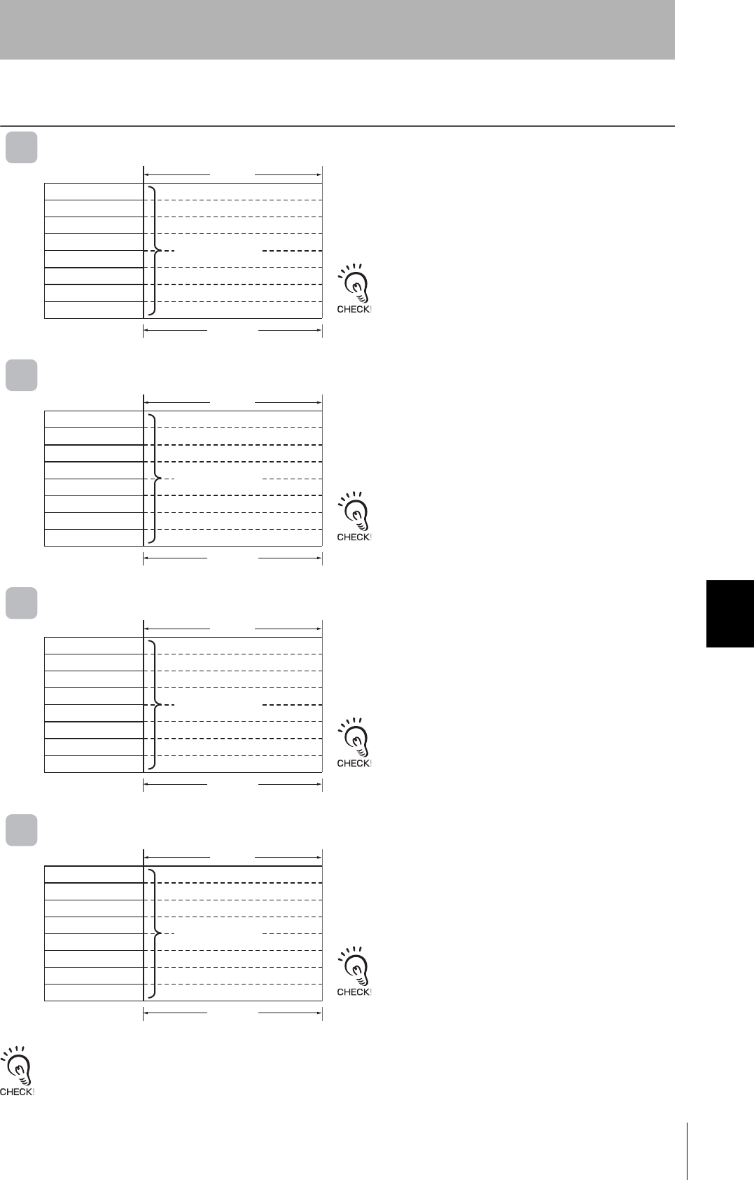
ID Tag Memory
V680-D1KP□□
V680-D2KF□□
V680-D8KF□□
V680-D32KF□□
メ モ リ へのア ク セスは16 ビ ッ ト 単位(2バイ ト 単位)に行われます。 ただ し、 1バイ ト ラ イ ト モー ド 指定の場合は、 8 ビ ッ ト 単位(1
バイ ト単位)となります。
Address Data
0000Hex
0001Hex
0002Hex
0003Hex User area
03E6Hex
03E7Hex
:
:
1 byte
EEPROM is used as memory in the Tags.
The memory capacity available to the user is 1,000 bytes,
including 0000H to 0003H (the Write Protection Setting Area).
Address Data
0000Hex
0001Hex
0002Hex
0003Hex User area
07CEHex
07CFHex
:
:
1 byte
FRAM is used as memory in the Tags.
The memory capacity available to the user is 1,000 bytes,
including 0000H to 0003H (the Write Protection Setting Area)
Address Data
0000Hex
0001Hex
0002Hex
0003Hex User area
1FFEHe
1FFFHe
:
:
1 byte
FRAM is used as memory in the Tags.
The memory capacity available to the user is 8,192 bytes,
including 0000H to 0003H (the Write Protection Setting Area)
Address Data
0000Hex
0001Hex
0002Hex
0003Hex User area
7FFEHe
7FFFHe
:
:
1 byte
FRAM is used as memory in the Tags.
The memory capacity available to the user is 32,744 bytes,
including 0000H to 0003H (the Write Protection Setting Area)

168
Section 7 ID Tag Memory Capacities and Memory Types (V680 Series)
RFID System
User's Manual
Section 7
Chemical Resistance
ID Tag Memory Capacities and Memory Types (V680 Series)
(As of December 2007)
Model Memory capacity
(user memory) Memory type Life expectancy
V680-D1KP52MT
1,000 bytes EEPROM
Overwrite operations: 100,000 times for each address at
25°C
Data retention: 10 years (up to 85°C)
V680-D1KP66T
V680-D1KP66MT
V680-D1KP66T-SP
V680-D2KF52M
2,000 bytes
FRAM
Number of accesses: 10 billion times
Data retention: 10 years (up to 55°C)
V680-D2KF67
V680-D2KF67M
V680-D8KF68 8,192 bytes
V680-D32KF68 32,744 bytes

173
RFID System
User's Manual
Section 7 Chemical Resistance of the Antennas, and Tags
Section 7
Chemical Resistance
Chemical Resistance of the Antennas, and Tags
Chemical Resistance of the Antennas
Applicable Models
ABS resin is used for case material and epoxy resin for filling material. Refer to the following lists and do not
use chemicals that affect ABS and epoxy resin.
Chemicals That Cause Deformations, Cracks, Etc.
Chemicals That May Cause Discoloration, Swelling, Etc.
Chemicals That Do Not Affect PPS Resin or Epoxy Resin
Note: The above results are from tests conducted a room temperature (23°C). Even if the chemicals
do not affect the ABS or epoxy resins at room temperature, they may affect the resins at higher or
lower temperatures. Check the chemicals carefully in advance.
V680-HS51 V680-HS52-W/R V680-HS63-W/R V680-HS65-W/R
ABS resin Epoxy resin
Trichlene, acetone, xylene, toluene, gasoline, creosol,
methylene chloride, phenol, cyclohexane, aqua regia,
chromic acid, sulfuric acid (90% RT), methyl ethyl
ketone, aniline, nitrobenzine, monochlorobenzine,
pyridine, nitric acid (60% RT), formic acid (80% RT)
Aqua regia, chromic acid, sulfuric acid (90% RT),
nitric acid (60% RT), ammonia solution, acetone,
methylene chloride, phenol
ABS resin Epoxy resin
Hydrochloric acid, alcohol, Freon, sodium hydroxide,
hydrogen peroxide, benzine, sulfuric acid (10% RT),
nitric acid (10% RT), phosphoric acid (85% RT),
ammonia solution
Sulfuric acid (10% RT), nitric acid (10% RT), hydrochlo-
ric acid (30% RT), acetic acid (50% RT), oxalic acid,
calcium hydroxide, benzine, creosol, alcohol, cyclohex-
ane, toluene, xylene, benzine, grease
ABS resin Epoxy resin
Ammonia, kerosine, mineral oil, developer, Yushiroken
S50, Chemi-Cool Z, Velocity No. 3, Yushiroken EEE-
30Y, petroleum, grease, acetic acid, oxalic acid, cal-
cium hydroxide, phosphoric acid (30% RT), hydrochlo-
ric acid (10% RT), potassium hydroxide
Ammonia, hydrochloric acid (10% RT), potassium
hydroxide, petroleum, gasoline, Yushiroken S50,
Chemi-Cool Z, Velocity No. 3, Yushiroken EEE-30Y

174
Section 7 Chemical Resistance of the Antennas, and Tags
RFID System
User's Manual
Section 7
Chemical Resistance
Chemical Resistance of Tags
Applicable Model
PPS resin is used for case material and epoxy resin for filling material. Refer to the following lists and do not
use chemicals that affect PPS and epoxy resin.
Tags cannot be used in applications with explosion-proof specifications.
Chemicals That Cause Deformations, Cracks, Etc.
Chemicals That May Cause Discoloration, Swelling, Etc.
Chemicals That Do Not Affect PPS Resin or Epoxy Resin
Note: The above results are from tests conducted a room temperature (23°C). Even if the chemicals
do not affect the PPS or epoxy resins at room temperature, they may affect the resins at higher
or lower temperatures. Check the chemicals carefully in advance.
V680-D1KP52MT V680-D2KF52M
PPS resin Epoxy resin
Aqua regia Aqua regia, chromic acid, sulfuric acid (90% RT),
nitric acid (60% RT), ammonia solution, acetone,
methylene chloride, phenol
PPS resin Epoxy resin
Nitric acid (60% RT) Sulfuric acid (10% RT), nitric acid (10% RT), hydrochlo-
ric acid (30% RT), acetic acid (50% RT), oxalic acid,
calcium hydroxide, benzine, creosol, alcohol, cyclohex-
ane, toluene, xylene, benzine, grease
PPS resin Epoxy resin
Hydrochloric acid (37%RT), sulfuric acid (98%RT),
nitric acid (40%RT), Hydrogen fluoride solution
(40%RT), chromic acid (40%RT), hydrogen peroxide
(28%RT), sodium hydroxide solution (60%RT),
ammonia solution (28%RT), sodium chloride (10%RT),
sodium carbonate (20%RT), sodium hypochlorite,
phenol solution (5%RT), glacial acetic acid, acetic acid,
oleic acid, Methyl alcohol (95%RT), ethyl alcohol
(95%RT), Ethyl acetate, sebacic acid, diethylhexyl,
acetone, diethyl ether, n-heptane, 2-2-4 trimethylpen-
tane, benzine, toluene, aniline, mineral oil, gasoline,
insulating oil, dichloroethylene, carbon tetrachloride
Ammonia, hydrochloric acid (10% RT), potassium
hydroxide, petroleum, gasoline, Yushiroken S50,
Chemi-Cool Z, Velocity No. 3, Yushiroken EEE-30Y,
methyl ethyl ketone, sodium hydroxide (10%RT)
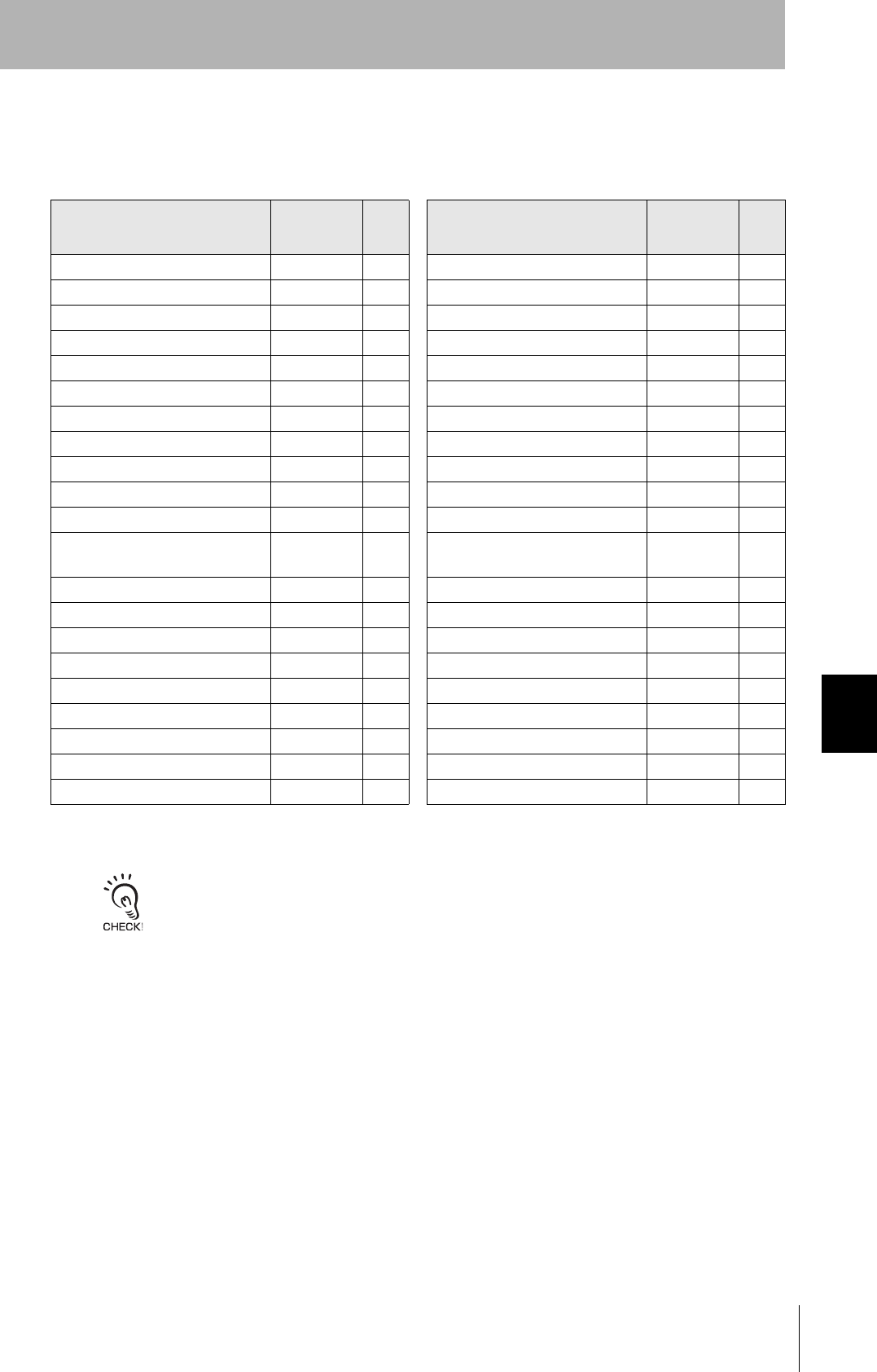
175
RFID System
User's Manual
Section 7 Chemical Resistance of the Antennas, and Tags
Section 7
Chemical Resistance
Applicable Models
The above table shows the extent of changes in PPS resin exposed to each chemical at room temperature
and at 90°C. If actual chemicals, concentrations, and temperatures are different from those shown in the
tables, always conduct tests under the actual conditions in which the Tags are to be used.
V680-D1KP66T/66MT
Chemical At room
tempera-
ture
At
90°CChemical At room
tempera-
ture
At
90°C
Hydrochloric acid 37% A A Sodium hypochlorite AA
10% A A Phenol solution 5% A A
Sulfuric acid 98% A B Glacial acetic acid AA
50% A A Acetic acid AA
30% A A Oleic acid AA
3% A A Methyl alcohol 95% A A
Nitric acid 60% B C Ethyl alcohol 95% A A
40% A B Ethyl acetate AA
10% A A Sebacic acid diethylhexyl AA
Hydrogen fluoride solution 40% A A Acetone AA
Chromic acid 40% A A Diethyl ether AA
Hydrogen peroxide solu-
tion 28% A B n-heptane AA
3% A A 2-2-4 trimethylpentane AA
Sodium hydroxide solution 60% A A Benzene AA
10% A A Toluene AA
1% A A Aniline AA
Ammonia solution 28% A B Mineral oil AA
10% A B Gasoline AA
Sodium chloride 10% A A Insulating oil AA
Sodium carbonate 20% A A Dichloroethylene AA
2% A A Carbon tetrachloride AA
A: Has no adverse effect, B: May cause discoloration, swelling, etc., C: Causes deformation, cracks, etc.
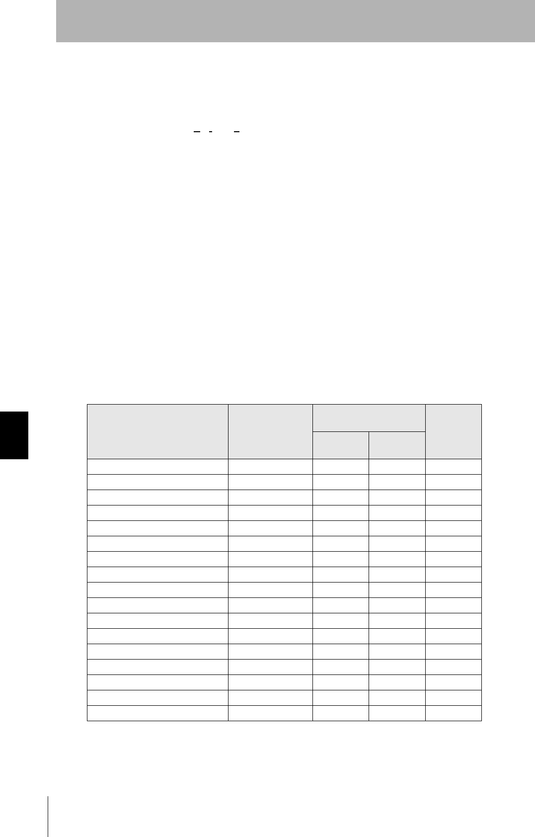
176
Section 7 Chemical Resistance of the Antennas, and Tags
RFID System
User's Manual
Section 7
Chemical Resistance
Applicable Models
Chemical Resistance of Fluoroplastic PFA (Reference)
PFA: Tetrafluorethylene-Perfluoroalkylvinyletheir Copolymer
Fluoroplastic PFA does not react with most chemicals except molten alkali metal, hot pressurized
fluorine (F2), and some halogen derivatives. The following tables show the results of tests in which PFA
was soaked in or exposed to commonly used organic and inorganic chemicals. In these tests, a
compression-molded test piece (1.3 mm thick) was soaked in the chemical at a specified temperature
for a week (168 houre) and taken out of the chemical, then the weight change, tensile strength, and
elongation of the test piece were immediately measured. If the change in the tensile strength is 15 % or
less, the cange in the elongation is 10 % or less, and the increase in the weight is less than 0.5 %, the
results of the test can be considered normal.
If PFA is exposed to trichloroacetic acid, tri-n-butyl phosphate, perchloroethylene, carbon thtrachloride,
and other liquids (which easily make resin surfaces wet) at a high temperature, it tends to increase its
weight due to absorption and reduce its tensile strength. Even when PFA absorbs chemicals and sol-
vents, its molecular structure will not change, If, however, PFA is subject to temperature or pressure
changes or mechanical damage when it has absorbed chemicals, the chemicals will repeatedly
expand and contract inside pfa, causing mechanical problems such as cracks and bulging. In fact, this
problem occurs with any kind of plastic.
Inorganic Chemicals
V680-D1KP66T-SP
Chemical name Test
temperature
(°C)
Resulting characteristics
(%) Weight
increase
rate (%)
Tensile
strength Elongation
concentrated hydrochloric acid 120 98 100 0.0
Concentrated sulfuric acid 120 95 98 0.0
Hydrofluoric acid (60%) 23 99 99 0.0
Fuming sulfuric acid 23 95 96 0.0
Aqua regia 120 99 100 0.0
Chromic acid (50%) 120 93 97 0.0
Consentrated nitric acid 120 95 98 0.0
Fuming nitric acid 23 99 99 0.0
Concentrated ammonia solution 66 98 100 0.0
Caustic soda (50%) 120 93 99 0.4
Hydrogen peroxide solution (30%) 23 93 95 0.0
Bromine 23 99 100 0.5
Chlorine 120 92 100 0.5
Ferrous chloride (25%) 100 93 98 0.0
Zinc chloride (25%) 100 96 100 2.7
Chlorosulfonic acid 151 91 100 2.7
Concentrated phosphoric acid 100 93 100 0.0
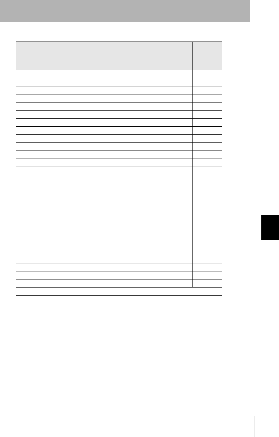
177
RFID System
User's Manual
Section 7 Chemical Resistance of the Antennas, and Tags
Section 7
Chemical Resistance
Organic Chemicals
Chemical name Test
temperature
(°C)
Resulting characteristics
(%) Weight
increase
rate (%)
Tensile
strength Elongation
Glacial acetic acid 118 95 100 0.4
Acetic anhydride 139 91 99 0.3
Trichloroacetic acid 196 90 100 2.2
Isooctane 99 94 100 0.7
Naphtha 100 91 100 0.5
Mineral oil 180 87 95 0.0
Toluene 110 88 100 0.7
o-creosol 191 92 96 0.2
Nitrobenzene 210 90 100 0.3
Benzyl alcohol 205 93 99 0.3
Aniline 185 94 100 0.3
n-butylamine 78 86 97 0.4
Ethylenediamine 117 96 100 0.1
Tetrahydrofuran 66 88 100 0.1
Benzaldehyde 179 90 99 0.5
Cyclohexane 156 92 100 0.4
Methyl ethyl ketone 80 90 100 0.4
Acetophenone 202 90 100 0.6
Dimethylphtalate 200 98 100 0.3
n-butyl acetate 125 93 100 0.5
Tri-n-butyl phosphate 200 91 100 2.0
Methylene chloride 40 94 100 0.8
Perchloroethylene 121 86 100 2.0
Carbon tetrachloride 77 87 100 2.3
Dimethyl formamide 154 96 100 0.2
Dimethyl sulfoxide 189 95 100 0.1
Dioxane 101 92 100 0.6
Reference: Fluoroplastics Handbook, The Nikkan Kogyo Shimbun Ltd. (Takaomi Satogawa)

178
Section 7 Chemical Resistance of the Antennas, and Tags
RFID System
User's Manual
Section 7
Chemical Resistance
Substances Extracted from Tag (Reference)
If chemicals penetrate into a Tag through PFA, ions may be extracted from the Tag.
Results of Ion-exchange Chromatography
A built-in Tag was soaked in hot water (100°C for 16 houres), and extracted ions were analyzed. The
results are shown below.
Extracted Ions (Concentration)
Cl: 0.5 ppm, Na+: 10 ppm, NH4+: 11 ppm, K+: 1.0 ppm
Results of ICP Emission Spectral Analysis
The V680-D1KP66T-SP Tag was soaked in condentrated hydrochloric acid (which can easily penetrate
through PFA) at 80°C fo 300 hours, then extracted substances were analyzed.
Extracted Substances (Concentration)
Si: 700 ng/ml, S: 1,000 ng/ml, Ca: 30 ng/ml
The chemical resistance and extracted substances presented here should be used for reference only. The
rates of change in Tag characteristics and the amounts of substances extracted will vary with temperatures
and chemical concentrations. Before using Tags under actual production environment, always conduct tests to
check for any problems

179
RFID System
User's Manual
Section 7 Chemical Resistance of the Antennas, and Tags
Section 7
Chemical Resistance
Applicable Models
Chemicals that affect Tags are shown below.
ABS resin is used for case material and epoxy resin for filling material. Refer to the following lists and do not
use chemicals that affect ABS and epoxy resin.
Tags cannot be used in applications with explosion-proof specifications.
Chemicals That Cause Deformations, Cracks, Etc.
Chemicals That May Cause Discoloration, Swelling, Etc.
Chemicals That Do Not Affect PPS Resin or Epoxy Resin
Note: The above results are from tests conducted a room temperature (23°C). Even if the chemicals
do not affect the ABS or epoxy resins at room temperature, they may affect the resins at higher
or lower temperatures. Check the chemicals carefully in advance.
V680-D2KF67/67M
ABS resin Epoxy resin
Trichlene, acetone, xylene, toluene, gasoline, creosol,
methylene chloride, phenol, cyclohexane, aqua regia,
chromic acid, sulfuric acid (90% RT), methyl ethyl
ketone, aniline, nitrobenzine, monochlorobenzine,
pyridine, nitric acid (60% RT), formic acid (80% RT)
Aqua regia, chromic acid, sulfuric acid (90% RT),
nitric acid (60% RT), ammonia solution, acetone,
methylene chloride, phenol
ABS resin Epoxy resin
Hydrochloric acid, alcohol, Freon, sodium hydroxide,
hydrogen peroxide, benzine, sulfuric acid (10% RT),
nitric acid (10% RT), phosphoric acid (85% RT),
ammonia solution
Sulfuric acid (10% RT), nitric acid (10% RT), hydrochlo-
ric acid (30% RT), acetic acid (50% RT), oxalic acid,
calcium hydroxide, benzine, creosol, alcohol, cyclohex-
ane, toluene, xylene, benzine, grease
ABS resin Epoxy resin
Ammonia, kerosine, mineral oil, developer, Yushiroken
S50, Chemi-Cool Z, Velocity No. 3, Yushiroken EEE-
30Y, petroleum, grease, acetic acid, oxalic acid, cal-
cium hydroxide, phosphoric acid (30% RT), hydrochlo-
ric acid (10% RT), potassium hydroxide
Ammonia, hydrochloric acid (10% RT), potassium
hydroxide, petroleum, gasoline, Yushiroken S50,
Chemi-Cool Z, Velocity No. 3, Yushiroken EEE-30Y
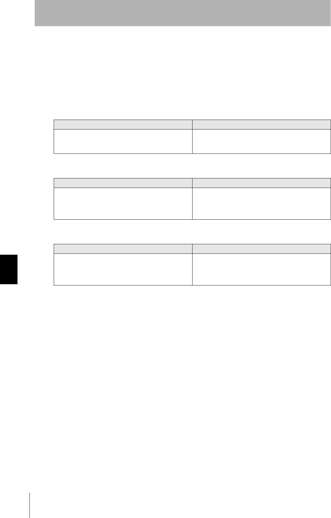
180
Section 7 Chemical Resistance of the Antennas, and Tags
RFID System
User's Manual
Section 7
Chemical Resistance
Applicable Model
Chemicals that affect Tags are shown below.
Polybutylene terephthalate (PBT) resin is used for case material and epoxy resin for filling material. Refer to
the following lists and do not use chemicals that affect PBT and epoxy resins.
Tags cannot be used in applications with explosion-proof specifications.
Chemicals That Cause Deformations, Cracks, Etc.
Chemicals That May Cause Discoloration, Swelling, Etc.
Chemicals That Do Not Affect PPS Resin or Epoxy Resin
Note: The above results are from tests conducted at room temperature (23°C). Even if the chemicals
do not affect the PPS or epoxy resins at room temperature, they may affect the resins at higher or lower
temperatures. Check the chemicals carefully in advance.
V680-D8KF68/D32KF68
PBT resin Epoxy resin
Acetone, trichloroethylene, ethylene dichloride, sodium
hydroxide, and other alkaline substances
Aqua regia, chromic acid, sulfuric acid (90% RT), nitric
acid (60% RT), liquid ammonia, acetone, methylene
chloride, phenol
PBT resin Epoxy resin
Hydrochloric acid (10% RT), acetic acid (5% RT), ben-
zene
Sulfuric acid (10% RT), nitric acid (10% RT), concen-
trated hydrochloric acid, acetic acid (50% RT), nitric
acid, calcium hydroxide, benzene, cresol, alcohol,
microhexanon, toluene, xylene, benzene, grease
PBT resin Epoxy resin
Nitric acid (30% RT), concentrated hydrochloric acid,
acetic acid, ethyl acetate (100% RT), potassium perma-
ganate (5% RH), ethyl acetate, carbon tetrachloride,
methanol, ethanol, gasoline
Ammonia, hydrochloric acid (10% RT), calcium hydrox-
ide, petroleum, gasoline, Yushiroken S50, Chemi-cool
Z, Velocity No. 3, Yushiroken EEE-30Y, methyl ethyl
ketone, sodium hydroxide
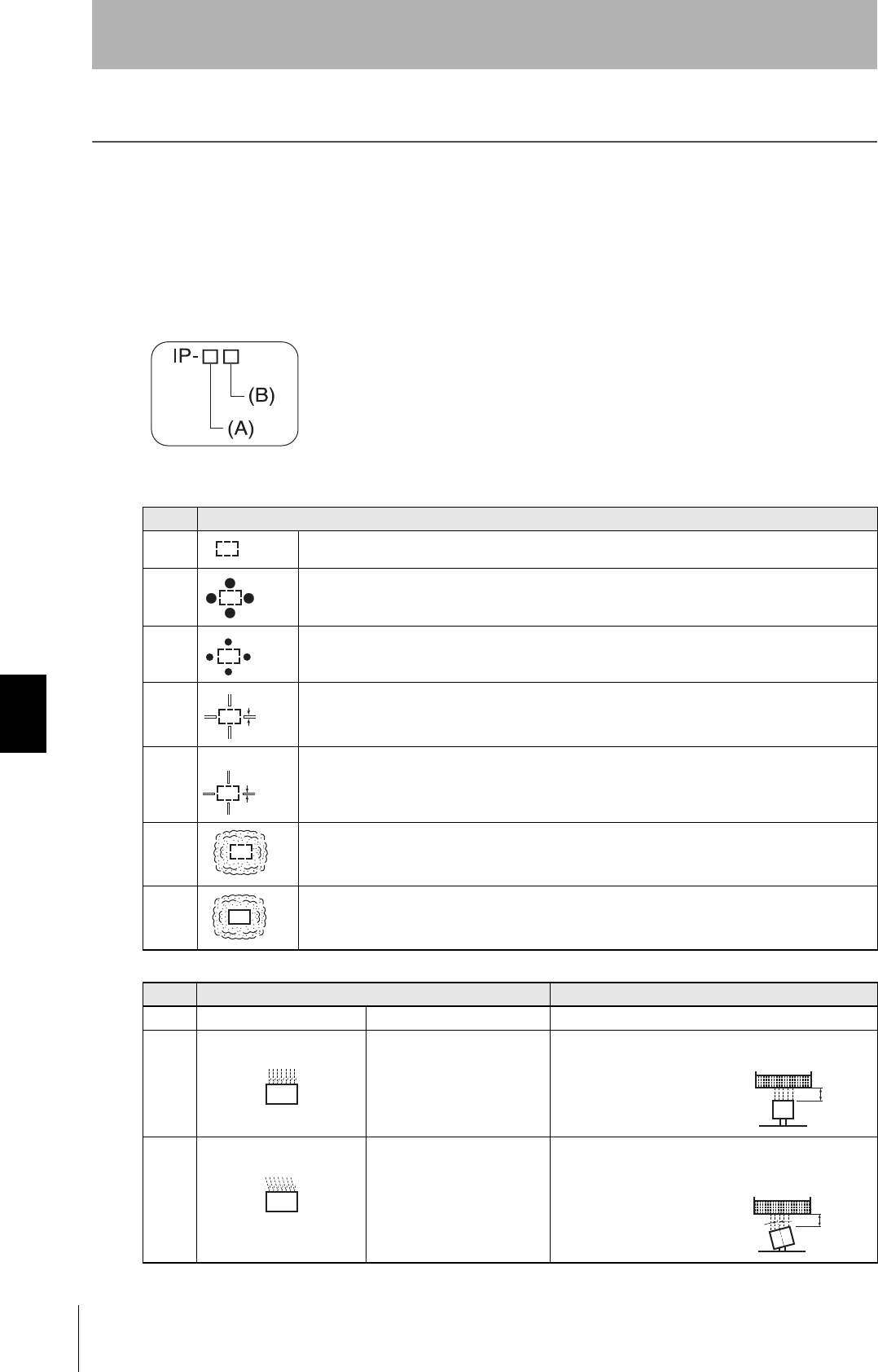
182
Section 7 Degree of Protection
RFID System
User's Manual
Section 7
Chemical Resistance
Degree of Protection
Ingress protection degrees (IP-@@) are determined by the following tests. Be sure to check the sealing capa-
bility under the actual operating environment and conditions before actual use.
IP indicates the ingress protection symbol.
IEC (International Electrotechnical Commission) Standards
IEC 60529: 1989-11
(A) First Digit: Degree of Protection from Solid Materials
(B) Second Digit: Degree of Protection Against Water
Degree Degree
0No protection
1
Protects against penetration of any solid object such as a hand that is 50 mm or more in diameter.
2
Protects against penetration of any solid object, such as a finger, that is 12.5 mm or more in diame-
ter.
3
Protects against penetration of any solid object, such as a wire, that is 2.5 mm or more in diameter.
4
Protects against penetration of any solid object, such as a wire, that is 1 mm or more in diameter.
5
Protects against penetration of dust of a quantity that may cause malfunction or obstruct the safe
operation of the product.
6
Protects against penetration of all dust.
Degree Protection Test method (with pure water)
0 No protection Not protected against water. No test
1 Protection against water
drops
Protects against vertical drops
of water towards the product.
Water is dropped vertically towards the product from
the test machine for 10 min.
2 Protection against water
drop
Protects against drops of
water approaching at a maxi-
mum angle of 15°to the left,
right, back, and front from ver-
tical towards the product.
Water is dropped for 2.5 min each (i.e., 10 min in total)
towards the product inclined 15° to the left, right, back,
and front from the test machine.
50 mm dia.
12.5 mm dia.
2.5 mm
1 mm
200 mm
200 mm
15˚
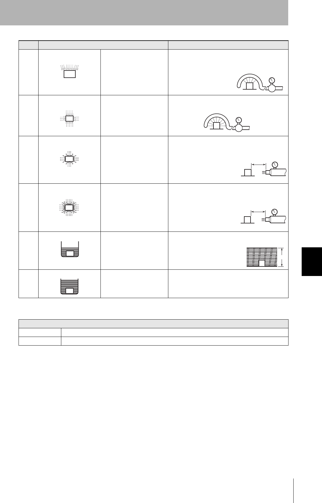
183
RFID System
User's Manual
Section 7 Degree of Protection
Section 7
Chemical Resistance
Oil resistance (OMRON in-house standard)
Note: This OMRON in-house standard confirms resistance to cutting and other oils. It is equivalent to the
former JEM standard.
3 Protection against sprin-
kled water
Protects against sprinkled
water approaching at a maxi-
mum angle of 60° from verti-
cal towards the product.
Water is sprinkled for 10 min at a maximum angle of
60° to the left and right from vertical from the test
machine.
4 Protection against water
spray
Protects against water spray
approaching at any angle
towards the product.
Water is sprayed at any angle towards the product for
10 min from the test machine.
5 Protection against water jet
spray
Protects against water jet
spray approaching at any
angle towards the product.
Water is jet sprayed at any angle towards the product
for 1 min per square meter for at least 3 min in total
from the test machine.
6 Protection against high
pressure water jet spray
Protects against high-pres-
sure water jet spray approach-
ing at any angle towards the
product.
Water is jet sprayed at any angle towards the product
for 1 min per square meter for at least 3 min in total
from the test machine.
7 Protection underwater Resists the penetration of
water when the product is
placed underwater at speci-
fied pressure for a specified
time.
The product is placed 1 m deep in water (if the product
is 850 mm max. in height) for 30 min.
8
(See Note)
Protection underwater Can be used continuously
underwater.
The test method is determined by the manufacturer and
user.
Protection
Oil-resistant No adverse affect from oil drops or oil spray approaching from any direction.
Oil-proof Protects against penetration of oil drops or oil spray approaching from any direction.
Degree Protection Test method (with pure water)
Water rate is 0.07
liter/min per hole.
Water rate is 0.07
liter/min per hole.
2.5 to 3 m
12.5 liter/min
Discharging nozzle: 6.3 dia.
2.5 to 3 m 100 liter/min
Discharging nozzle: 6.3 dia.
1 m

184 RFID System
User's Manual
Revision History
A manual revision code appears as a suffix to the catalog number at the bottom of the front and rear pages.
Revision code Date Revised contents
01 October 2006 Original production
02 May 2007 Added items for V680-D8KF68/-D32KF68 ID Tags.
03 July 2007 Added items for V680-A81, V680-HS65 Antenna, and the overseas regulations
and standards.
03A September 2007 Added information on metal on back surface of the V680-HS65, corrected Tag
specifications, and made other minor corrections.
04 December 2007 Added item for V680-HS51 Antenna, the overseas regulations and standards, ,
and made other minor corrections.
Cat. No.: Z248-E1-04
Revision code

Authorized Distributor:
OMRON Corporation
Industrial Automation Company
Sensing Devices Division H.Q.
Industrial Sensors Division
Shiokoji Horikawa, Shimogyo-ku,
Kyoto, 600-8530 Japan
Tel: (81)75-344-7022/Fax: (81)75-344-7107
Regional Headquarters
OMRON EUROPE B.V.
Sensor Business Unit
Carl-Benz-Str. 4, D-71154 Nufringen,
Germany
Tel: (49) 7032-811-0/Fax: (49) 7032-811-199
OMRON ELECTRONICS LLC
One Commerce Drive Schaumburg,
IL 60173-5302 U.S.A.
Tel: (1) 847-843-7900/Fax: (1) 847-843-7787
OMRON ASIA PACIFIC PTE. LTD.
No. 438A Alexandra Road # 05-05/08 (Lobby 2),
Alexandra Technopark, Singapore 119967
Tel: (65) 6835-3011/Fax: (65) 6835-2711
OMRON (CHINA) CO., LTD.
Room 2211, Bank of China Tower,
200 Yin Cheng Zhong Road,
Pu Dong New Area, Shanghai, 200120, China
Tel: (86) 21-5037-2222/Fax: (86) 21-5037-2200
Cat. No. Z279-E1-01
In the interest of product improvement, specifications are
subject to change without notice.
Printed in Japan
0308-0.3C (1006)