User Manual
RFID SYSTEM
V680 Series
User’s Manual
FL Remote ID
V680-HAM42-FRT
Antenna
V680-HS63-SP
ID Tag
V680-D1KP66T-SP
Introduction
Thank you for purchasing a V680-series RFID System. This manual describes the functions, performance, and
application methods needed for optimum use of the V680-series RFID System.
Please observe the following items when using the RFID System.
• Allow the RFID System to be installed and operated only by qualified specialist with a sufficient knowledge of
electrical systems.
• Read and understand this manual before attempting to use the RFID System and use the RFID System correctly.
• Keep this manual in a safe and accessible location so that it is available for reference when required.

Warranty, Limitations of Liability
< WARRANTY >
OMRON's exclusive warranty is that the products are free from defects in materials and workmanship for a
period of one year (or other period if specified) from date of sale by OMRON.
OMRON MAKES NO WARRANTY OR REPRESENTATION, EXPRESS OR IMPLIED, REGARDING
NON-INFRINGEMENT, MERCHANTABILITY, OR FITNESS FOR PARTICULAR PURPOSE OF THE
PRODUCTS. ANY BUYER OR USER ACKNOWLEDGES THAT THE BUYER OR USER ALONE
HAS DETERMINED THAT THE PRODUCTS WILL SUITABLY MEET THE REQUIREMENTS OF
THEIR INTENDED USE. OMRON DISCLAIMS ALL OTHER WARRANTIES, EXPRESS OR
IMPLIED.
< LIMITATIONS OF LIABILITY >
OMRON SHALL NOT BE RESPONSIBLE FOR SPECIAL, INDIRECT, OR CONSEQUENTIAL
DAMAGES, LOSS OF PROFITS OR COMMERCIAL LOSS IN ANY WAY CONNECTED WITH THE
PRODUCTS, WHETHER SUCH CLAIM IS BASED ON CONTRACT, WARRANTY, NEGLIGENCE,
OR STRICT LIABILITY.
In no event shall the responsibility of OMRON for any act exceed the individual price of the product on
which liability is asserted.
IN NO EVENT SHALL OMRON BE RESPONSIBLE FOR WARRANTY, REPAIR, OR OTHER CLAIMS
REGARDING THE PRODUCTS UNLESS OMRON'S ANALYSIS CONFIRMS THAT THE PRODUCTS
WERE PROPERLY HANDLED, STORED, INSTALLED, AND MAINTAINED AND NOT SUBJECT TO
CONTAMINATION, ABUSE, MISUSE, OR INAPPROPRIATE MODIFICATION OR REPAIR.

Application Considerations
< SUITABILITY FOR USE >
OMRON shall not be responsible for conformity with any standards, codes, or regulations that apply to the
combination of the products in the customer's application or use of the products.
At the customer's request, OMRON will provide applicable third party certification documents identifying
ratings and limitations of use that apply to the products. This information by itself is not sufficient for a
complete determination of the suitability of the products in combination with the end product, machine,
system, or other application or use.
The following are some examples of applications for which particular attention must be given. This is
not intended to be an exhaustive list of all possible uses of the products, nor is it intended to imply that the
uses listed may be suitable for the products:
z Outdoor use, uses involving potential chemical contamination or electrical interference, or conditions
or uses not described in this manual.
z Nuclear energy control systems, combustion systems, railroad systems, aviation systems, medical
equipment, amusement machines, vehicles, safety equipment, and installations subject to separate
industry or government regulations.
z Systems, machines, and equipment that could present a risk to life or property.
Please know and observe all prohibitions of use applicable to the products.
NEVER USE THE PRODUCTS FOR AN APPLICATION INVOLVING SERIOUS RISK TO LIFE OR
PROPERTY WITHOUT ENSURING THAT THE SYSTEM AS A WHOLE HAS BEEN DESIGNED TO
ADDRESS THE RISKS, AND THAT THE OMRON PRODUCTS ARE PROPERLY RATED AND
INSTALLED FOR THE INTENDED USE WITHIN THE OVERALL EQUIPMENT OR SYSTEM.
< PROGRAMMABLE PRODUCTS >
OMRON shall not be responsible for the user's programming of a programmable product, or any
consequence thereof.
Disclaimers
< PERFORMANCE DATA >
Performance data given in this manual is provided as a guide for the user in determining suitability and does not
constitute a warranty. It may represent the result of OMRON’s test conditions, and the users must correlate it to actual
application requirements. Actual performance is subject to the OMRON Warranty and Limitations of Liability.
< CHANGE IN SPECIFICATIONS >
Product specifications and accessories may be changed at any time based on improvements and other reasons.
It is our practice to change model numbers when published ratings or features are changed, or when
significant construction changes are made. However, some specifications of the products may be changed
without any notice. When in doubt, special model numbers may be assigned to fix or establish key
specifications for your application on your request. Please consult with your OMRON representative at
any time to confirm actual specifications of purchased products.
< DIMENSIONS AND WEIGHTS >
Dimensions and weights are nominal and are not to be used for manufacturing purposes, even when
tolerances are shown.
< ERRORS AND OMISSIONS >
The information in this manual has been carefully checked and is believed to be accurate; however, no
responsibility is assumed for clerical, typographical, or proofreading errors, or omissions.
1. Meanings of Signal Words
The following signal words are used in this manual.
WARNING
Indicates a potentially hazardous situation which, if not avoided, will result
in minor or moderate injury, or may result in serious injury or death.
Additionally there may be significant property damage.
Indicates general prohibitions for which there is no specific symbol.
!
This product is not designed or rated for ensuring safety of persons.
Do not use it for such purposes.
!WARNING
Regulations and Standards
The V680-HAM42-FRT and V680-HS63-SP conform to the following overseas regulations and standards.
1. Japan
Japan Radio Law
Equipment using high frequencies: Inductive Reading/Writing Communications Equipment
Conforming standards: Inductive Reading/Writing Communications Equipment; Standard: ARIB STD-T82
2. The United States, Canada
FCC Rules (Federal Communications Commission), IC Rules (Industry Canada)
This product complies with Part 15 Subpart C and Part 15 Subpart B of the FCC Rules and IC Rules.
FCC Part15 subpart C, RSS-Gen
FCC ID : E4E6CYSIDV6800507
IC : 850J-V6800507
This device complies with part 15 of the FCC Rules and RSS-Gen of IC Rules. Operation is subject to the following two conditions:
(1) This device may not cause harmful interference.
(2) This device must accept any interference received, including interference that may cause undesired operation.
FCC Part15 subpart B
NOTICE
This equipment has been tested and found to comply with the limits for a Class A digital device, pursuant to part 15 of the FCC
Rules. These limits are designed to provide reasonable protection against harmful interference when the equipment is operated in a
commercial environment.
This equipment generates, uses and can radiate radio frequency energy and, if not installed and used in accordance with the
instructions, may cause harmful interference to radio communications. Operation of this equipment in a residential area is likely to
cause harmful interference in which case the user will be required to correct the interference at his own expense.
ICES-003
This class A digital apparatus complies with Canadian ICES-003.
WARNING
Changes or modifications not expressly approved by the party responsible for compliance could void the user's authority to operate
the equipment.
Do not remove the ferrite core (TDK Type ZCAT2032-0930) installed on the cables to suppress RF interference.
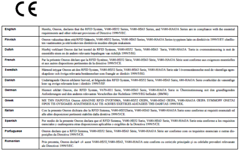
3. Europe
EC Declaration of Conformity
Hereby, OMRON Corporation declares that this RFID System, Antenna V680-HS63-SP and Amplifier
V680-HAM42-FRT. Amplifier and Antenna are in compliance with essential requirements and other relevant
provisions of Directive 1995/5/EC, and satisfy tests for the appropriate requirements of the following relevant
standards.
Radio : EN 300 330-2V1.1.1 (06-2001)
EN 300 330-1V1.3.2 (12-2002)
EMC : EN 301 489-3V1.4.1 (08-2002)
EN 301 489-1V1.5.1 (11-2004)
Safety : EN 61010-1: 2001 (2nd Edition)
Changes or modifications not expressly approved by the party responsible for compliance could void the user's
authority to operate the equipment.
Do not remove the ferrite core (TDK Type ZCAT2030-0930A) installed on the cables to suppress RF
interference.
Precautions for Safe Use
Be sure to observe the following precautions to ensure safe use of the Products.
1. Do not use the Products in environments with flammable, explosive, or corrosive gasses.
2. Do not attempt to disassemble, repair, or modify any Product.
3. Tighten mounting screws securely.
4. If any cable has a locking mechanism, make sure that it has been locked before using the cable.
5. Do not allow water or pieces of wire to enter from openings in the case. Doing so may cause fire or electric shock.
6. Turn OFF the Controller power supply before mounting or removing an Antenna or Amplifier.
7. If an error is detected in any Product, immediately stop operation and turn OFF the power supply. Consult with an
OMRON representative.
8. Dispose of the Products as industrial waste.
9. Observe all warnings and precautions given in the body of this manual.
10.Do not touch the product immediately after usage at high temperatures. Doing so may occasionally result in burning.
Precautions for Correct Use
Always observe the following precautions to prevent operation failures, malfunctions, and adverse effects on
performance and equipment.
1. Installation Location
Do not install the product in the following locations:
・Locations subject to corrosive gases, dust, dirt, metal powder, or salt
・Locations where the specified ambient operating temperature range is exceeded
・Locations subject to extreme temperature changes that may result in condensation
・Locations where the specified ambient operating humidity range is exceeded
・Locations where the product would be directly subjected to vibration or shock exceeding specifications
・Locations subject to contact with water, oil, or chemicals
2. Installation
・The product uses the 13.56MHz frequency band to communicate with Tags. Some devices, such as some
tranceivers, motors, inverters, and switch mode power supplies, generate electromagnetic waves (i.e., noise) that
can affect communications with the Tags. If any of these devices are nearby, communications with Tags may be
affected or Tags may be destroyed, If the product is to be used near such devices, check the effects on
communications before using the product.
・To minimize the general influence of noise, follow the following precautions:
(1)Ground the earth terminal of this product and any metallic material located around the product to 100 Ω or less.
(2)Keep product wiring away from high voltage or heavy current.
・Attach the accompanying ferrite core (Type:ZCAT2032-0930 made by TDK Corp.) around the cables that are
connected with the power and grounding terminals.
・The product does not provide a water-proof structure. Do not use it where mists are present.
・Communications performance may be reduced due to mutual interference if more than one Read/Write Antenna
is installed in the same vicinity.
Refer to this Manual and confirm that there is no mutual interference between Read/Write Antennas.
3. Storage
Do not store the product in the following locations:
・Locations subject to corrosive gases, dust, dirt, metal powder, or salt
・Locations where the specified ambient storage temperature range is exceeded
・Locations subject to extreme temperature changes that may result in condensation
・Locations where the specified ambient storage humidity range is exceeded
・Locations where the product would be directly subjected to vibration or shock exceeding specifications
・Locations subject to contact with water, oil, or chemicals
4. Cleaning
・Do not use thinners for cleaning. Resin materials and the case coating will be dissolved by thinners, benzenes,
acetones and kerosenes.
1. Meanings of Signal Words ....................................................................................................................5
1. Product overview...............................................................................................................................13
1.1. Features.....................................................................................................................................13
1.2. System Configuration .................................................................................................................13
2. Part names and functions ....................................................................................................................14
2.1. Part names .................................................................................................................................14
2.2. I/O Specifications .......................................................................................................................19
2.2.1. Allocated I/O ......................................................................................................................19
2.2.2. Signal functions ..................................................................................................................20
2.3. Memory map..............................................................................................................................21
2.4. ID tag communication functions...................................................................................................22
2.4.1. Operational mode ................................................................................................................22
3. Communicating with the plc ...............................................................................................................23
3.1. Command correspondence...........................................................................................................23
3.1.1. Data read ............................................................................................................................23
3.1.2. Data write...........................................................................................................................24
3.1.3. Bit set.................................................................................................................................25
3.1.4. Bit clear..............................................................................................................................26
3.1.5. Data fill ..............................................................................................................................27
3.1.6. Noise measurement..............................................................................................................28
3.2. Timing chart ..............................................................................................................................29
4. Appendix ..........................................................................................................................................30
4.1. Specifications.............................................................................................................................30
4.2. Dimensions................................................................................................................................32
1. Product overview
1.1. Features
The RFID system: V680 series employs the electromagnetic induction type, and is a product in accordance with
International Standard ISO/IEC18000-3(ISO/IEC15693) of the RFID system.
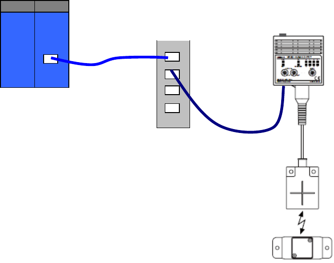
1.2. System Configuration
PLC: FL REMOTE Master unit
HUB
FL REMOTE ID
V680-HAM42-FRT
Antenna
V680-HS63-SP
ID Tag
V680-D1KP66T-SP
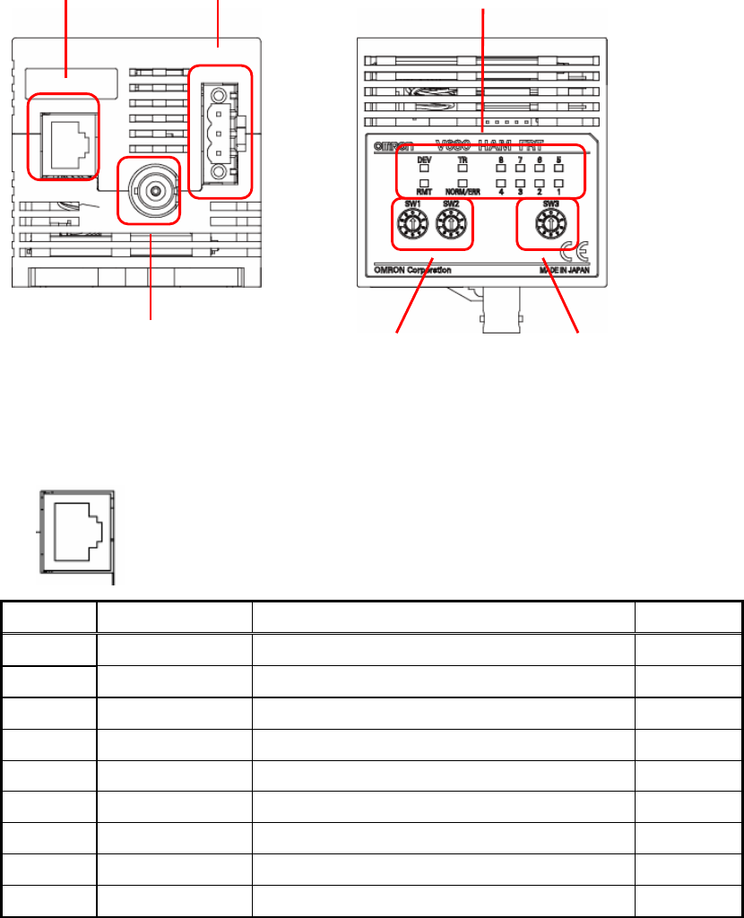
2. Part names and functions
2.1. Part names
- Ethernet Connector: Connector for FL REMOTE
PIN No Name Description I/O
1 TX_D1+ Tranceive data + output
2 TX_D1- Tranceive data - output
3 RX_D2+ Receive data + input
4 - - -
5 - - -
6 RX_D2- Receive data - input
7 - - -
8 - - -
Hood - FG -
Ethernet connector Power supply connector
Antenna connector Node No. switch Mode switch
Display LED
<Bottom view>
1
8
<Front view>
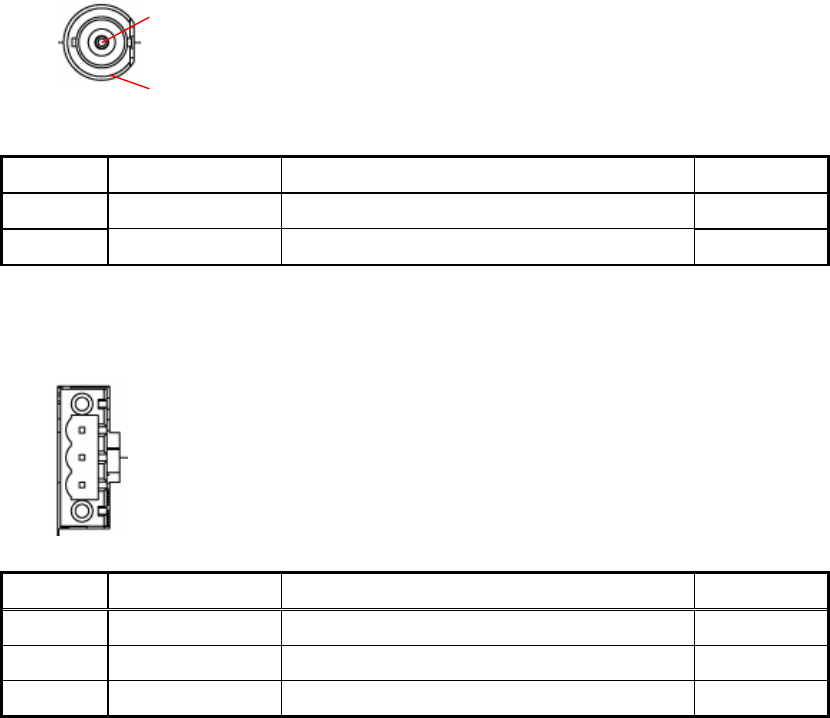
- Antenna connector: connector for antenna
PIN No Name Description I/O
1 S Signal -
2 GND Analog ground -
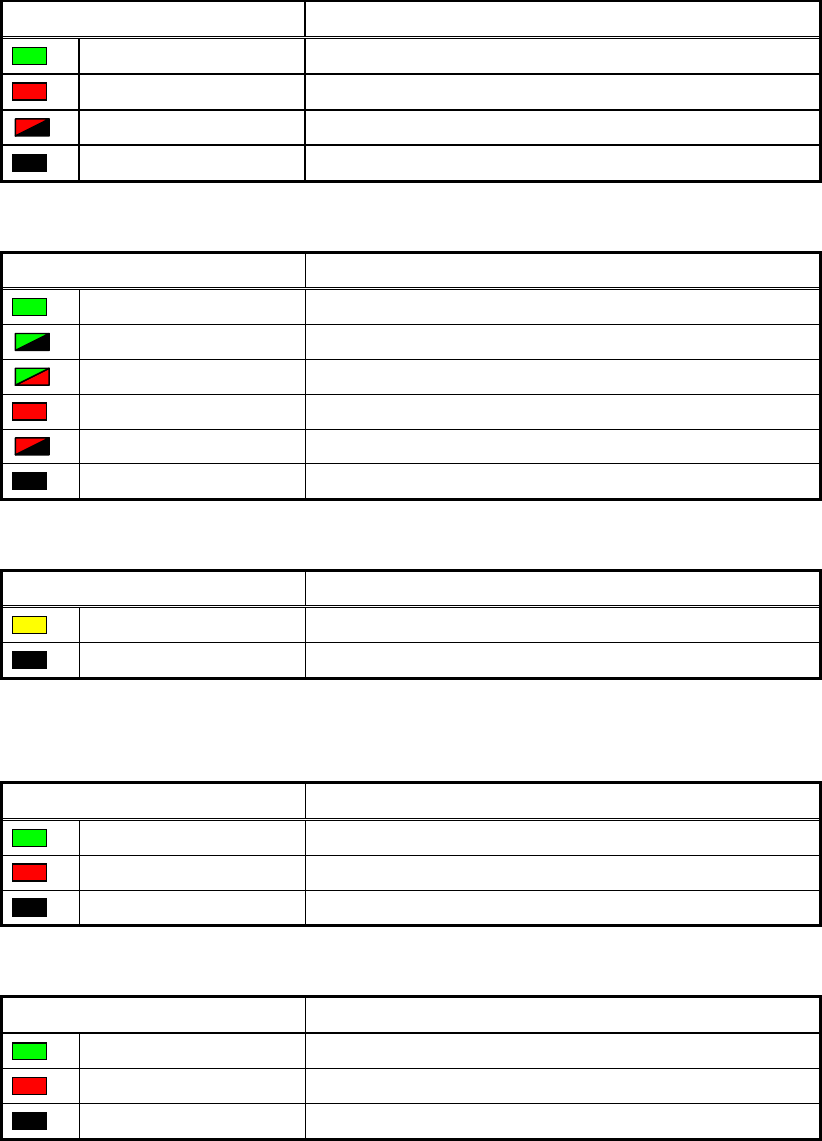
- Power supply connector: connected to the 24VDC power supply
Please use the bundled connector.
PIN No Name Description I/O
1 24V 24VDC terminal -
2 GND Ground terminal -
3 GR Functional earth terminal -
Please use recommended power supply unit: S8VS-03024.
1
3
1
2
- Display LED
> DEV(Device Status indicator)
Status Meaning
Green Normal
Red Serious malfunction
Red(blinking) Slight malfunction
Unlit Power off
>RMT(Remote Status indicator)
Status Meaning
Green Connected to network/ Transferring FL Remote IO
Green (blinking) Connected to network/ No transferring FL Remote IO
Green and Red (blinking) Connected to network/ Setting error
Red Duplicate node address
Red (blinking) Not connected to network
Unlit Not connected to network
>TR(ID transmission indicator)
Status Meaning
Yellow Communicating to ID Tag
Unlit Standby
>NORM/ERR(ID transmission result indicator)
Status Meaning
Green Communication normal finish
Red Communication error
Unlit standby
>DATA(Data indicator)
Status Meaning
Green Indicate communicating data contents
Red Indicate error code
Unlit standby

- Node No. switch
Please set node no. with the Node No. switch that is used as the low rank value of Internet Protocol address.
192.168.250. **.
Item Description
Setting method two BCD rotary switches
Setting range 01 to 31
- Mode switch
Please set the mode of FL REMOTE ID with the mode switch.
No Name Description
0 Trigger mode When the trigger signal is input from the plc, FL REMOTE
ID begins the communication with the ID tag, and outputs
the communication result to the plc.
1 Auto mode When the ID tag approaches the antenna front, FL REMOTE
ID begins the communication with the ID tag, and outputs
the communication result to the plc.
2 Test mode FL REMOTE ID repeatedly executes the ID Tag read of eight
bytes from 00 addresses without the control from the plc
others - mode error

2.2. I/O Specifications
2.2.1. Allocated I/O
The V680-HAM42-FRT occupies 64 input bits (4 words) and 64 output bits (4 words) of the Programmable
Controller. The occupied CIO varies according to the node number that is set by the Node No. switch of
V680-HAM42-FRT.
<Master unit to Slave unit>
Output bits
15 14 13 12 11 10 9 8 7 6 5 4 3 2 1 0
CMD LEN CIO
+0
OUTPUT
TIME
WR
PROTECT
VERIFY HISPD TRG/
~INHIBIT 3 2 1 0 3 2 1 0
ADDR CIO
+1 15 14 13 12 11 10 9 8 7 6 5 4 3 2 1 0
OD1 OD0 CIO
+2 7 6 5 4 3 2 1 0 7 6 5 4 3 2 1 0
OD3 OD2 CIO
+3 7 6 5 4 3 2 1 0 7 6 5 4 3 2 1 0
<Slave unit to Master unit>
Input bits
15 14 13 12 11 10 9 8 7 6 5 4 3 2 1 0
ERR CIO
+0
TEST
MODE
BUSY RUN
3 2 1 0
NORM
ERR_SUB CIO
+1
6 5 4 3 2 1 0
ID1 ID0 CIO
+2 7 6 5 4 3 2 1 0 7 6 5 4 3 2 1 0
ID3 ID2 CIO
+3 7 6 5 4 3 2 1 0 7 6 5 4 3 2 1 0

2.2.2. Signal functions
<Master unit to Slave unit>
Signal Name Description
OD0-0 to 7
OD1-0 to 7
OD2-0 to 7
OD3-0 to 7
Data output Output write data to the ID tag
ADDR0 to 15 Address Specify start address for reading or writing.
Setting range: 0000H to FFFFH
LEN0 to 4 Data length READ, WRITE; specify the data length by the number of bytes
Setting range: 1H to 4H
DATA FILLI; specify the data length by the number of blocks
Setting range: 0H to FH
CMD0 to 3 Command Specify the executing command
0000B Data read
0001B Data write
0010B Bit set
0011B Bit clear
0100B Data fill
1111B Noise measurement
Trigger mode When this signal is “1", FL REMOTE ID begins the communication
with the ID tag
TRG/~INHIBIT Trigger input/~Inhibit
Input
Auto mode When this signal is “0", FL REMOTE ID stops the communication
with the ID tag
HISPD High-speed Data
Transmission setting
“0” Normal mode
“1” High speed mode
VERIFY Write verification “0” With write verification
“1” Without write verification
WR PROTECT Write protection
function disable
“0” Enabled
“1” Disabled
OUTPUT TIME Output time setting “0” 100ms
“1” 500ms
<Slave unit to Master unit>
Signal Name Description
ID0-0 to 7
ID1-0 to 7
ID2-0 to 7
ID3-0 to 7
Data input Input read data from the ID tag
RUN RUN Turns “1” when FL REMOTE ID is operating normally and the communications are possible
with the plc
BUSY BUSY Output when a tag communications continues
NORM Normal output Output when communications with the ID tag are completed normally
ERR0 Error 0 output Output when communications with the ID tag are not completed normally
ERR1 Error 1 output Output when the command is illegal
ERR2 Error 2 output Output in the mode error
ERR3 Error 3 output Output when FL REMOTE ID is inoperative
ERR_SUB0 Error sub 0 No tag error
ERR_SUB1 Error sub 1 ID tag communication error
ERR_SUB2 Error sub 2 ID tag address error
ERR_SUB3 Error sub 3 Write protect error
ERR_SUB4 Error sub 4 Verification error
ERR_SUB5 Error sub 5 System error
ERR_SUB6 Error sub 6 System error
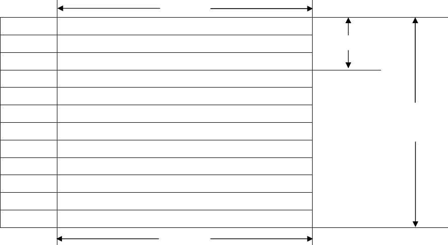
2.3. Memory map
ID tag has a memory area of up to 1 Kbytes. Each address of the memory area specifies one byte. A single byte of
data can be written to one address.
Address Data
0000H
to
0007H
1block
0008H
to
0100H
to
0200H
to
0300H
to
03E7H
1000bytes
1byte
2.4. ID tag communication functions
FL remote ID sets the operating mode with the mode switch, selects the command, adds the option that
operates the command, and communicates with the ID tag.
2.4.1. Operational mode
In the operating mode, there are three modes.
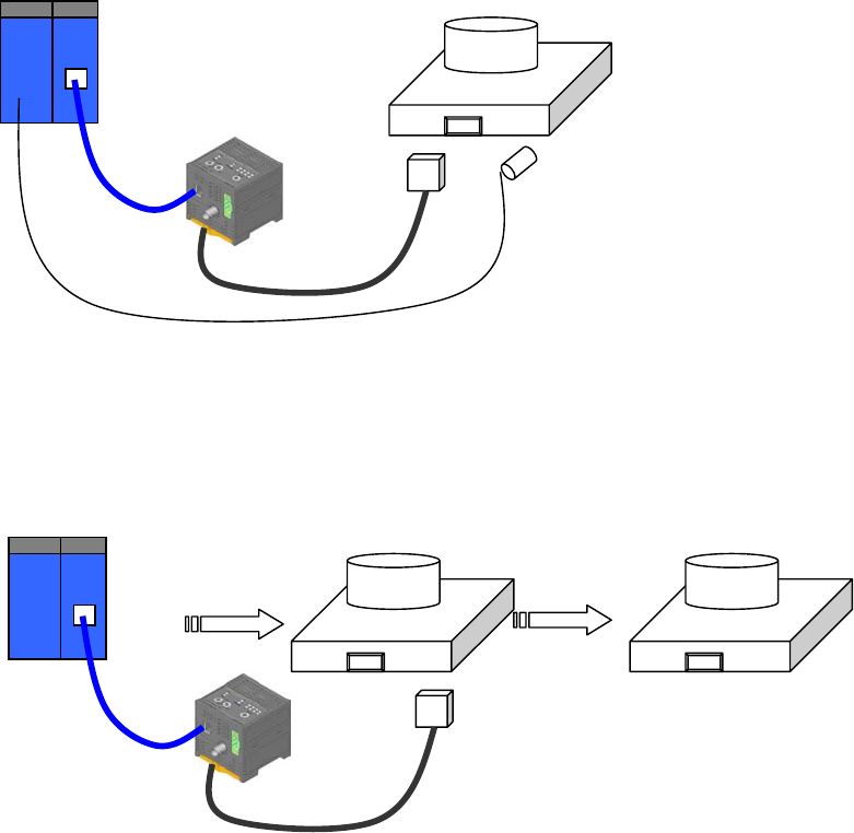
2.4.1.1. Trigger mode
The ID tag installed in work or the palette is detected in the communication area of the antenna by the
sensor or the switch, and the control signal (trigger signal) is output from the plc to FL REMOTE ID. This
FL REMOTE ID begins the communication with the ID tag, and outputs the result to the plc by the signal.
2.4.1.2. Auto mode
When the ID tag installed in work or the palette enters in the communication area of the antenna, FL
REMOTE ID begins the ID tag and the communication, and outputs the result to the plc.
3. Communicating with the plc
3.1. Command correspondence
3.1.1. Data read
<Master unit to Slave unit>
Signal Length Data Description
CMD 4 0000B Data read
LEN 4 1H to 4H Data length
ADDR 16 0000H to FFFFH Start address
<Slave unit to Master unit>
Signal Length Data Description
NORM 1 0 or 1 Normal completion
ERR* 1 0 or 1 Abnormal completion
ERR_SUB* 1 0 or 1 Abnormal completion for ID tag communication
ID 32 - Read data
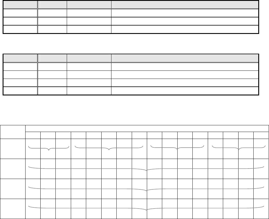
<Example>
Data read of 3 bytes from 120H addresses
Output bits
15 14 13 12 11 10 9 8 7 6 5 4 3 2 1 0
CIO+0
0 0 0 * * * * * 0 0 0 0 0 0 1 1
CIO+1
0 0 0 0 0 0 0 1 0 0 1 0 0 0 0 0
CIO+2
0 0 0 0 0 0 0 0 0 0 0 0 0 0 0 0
CIO+3
0 0 0 0 0 0 0 0 0 0 0 0 0 0 0 0
Data read 3 bytes
Change the setting if necessary
Fixed
120H address
Fixed
Fixed

3.1.2. Data write
<Master unit to Slave unit>
Signal Length Data Description
CMD 4 0001B Data write
LEN 4 1H to 4H Data length
ADDR 16 0000H to FFFFH Start address
OD 32 - Write data
<Slave unit to Master unit>
Signal Length Data Description
NORM 1 0 or 1 Normal completion
ERR* 1 0 or 1 Abnormal completion
ERR_SUB* 1 0 or 1 Abnormal completion for ID tag communication
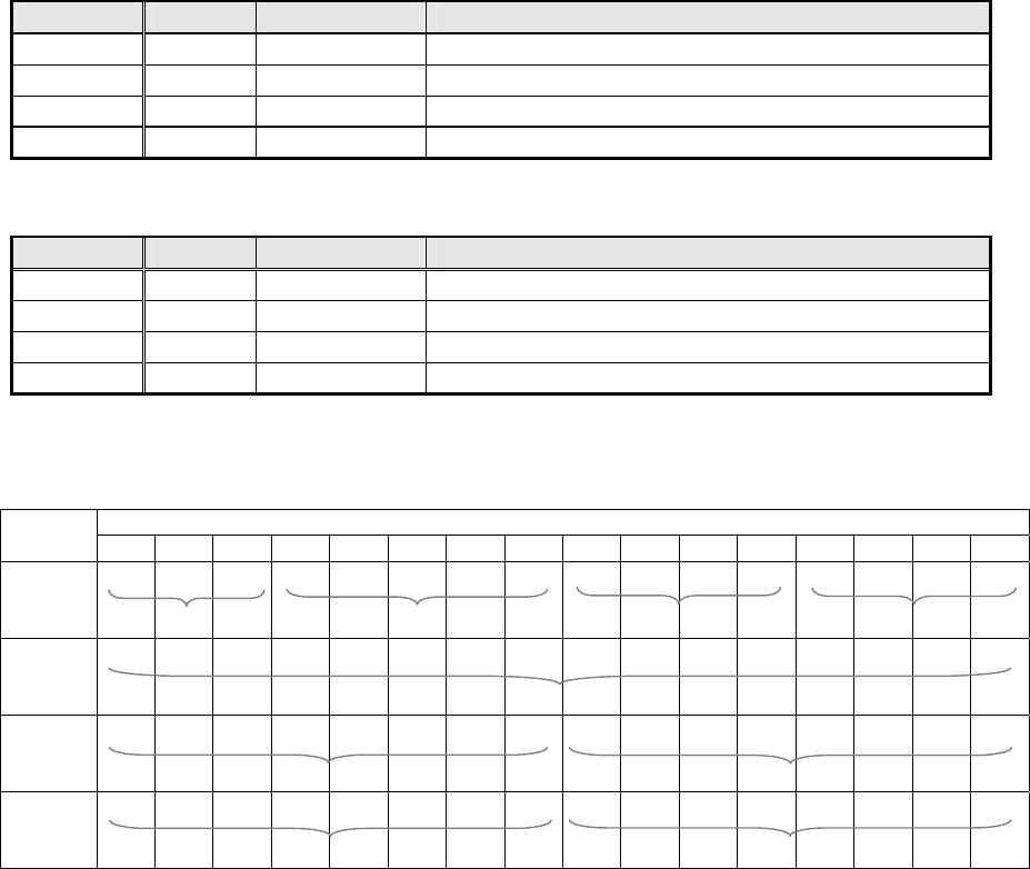
<Example>
Data write of 3 bytes from 321H addresses
Output bits
15 14 13 12 11 10 9 8 7 6 5 4 3 2 1 0
CIO+0
0 0 0 * * * * * 0 0 0 1 0 0 1 1
CIO+1
0 0 0 0 0 0 1 1 0 0 1 0 0 0 0 1
CIO+2
0 1 1 1 1 0 0 0 0 0 0 1 0 0 1 0
CIO+3
0 0 0 0 0 0 0 0 1 0 1 0 1 0 1 1
Data write 3 bytes
Change the setting if necessary
Fixed
321H address
12H
Fixed
78H
ABH

3.1.3. Bit set
<Master unit to Slave unit>
Signal Length Data Description
CMD 4 0010B Bit set
LEN 4 1H to 4H Data length
ADDR 16 0000H to FFFFH Start address
OD 32 - Bit set data
<Slave unit to Master unit>
Signal Length Data Description
NORM 1 0 or 1 Normal completion
ERR* 1 0 or 1 Abnormal completion
ERR_SUB* 1 0 or 1 Abnormal completion for ID tag communication
ID 32 - Data after bit set
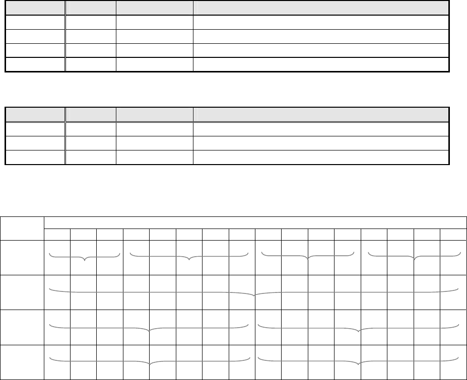
<Example>
Bit set of 1 byte from FFH addresses
Output bits
15 14 13 12 11 10 9 8 7 6 5 4 3 2 1 0
CIO+0
0 0 0 * * * * * 0 0 1 0 0 0 0 1
CIO+1
0 0 0 0 0 0 0 0 1 1 1 1 1 1 1 1
CIO+2
0 0 0 0 0 0 0 0 0 0 0 0 0 1 0 1
CIO+3
0 0 0 0 0 0 0 0 0 0 0 0 0 0 0 0
Bit set 1byte
Change the setting if necessary
Fixed
FFH address
05H
Fixed
Fixed
Fixed
3.1.4. Bit clear
<Master unit to Slave unit>
Signal Length Data Description
CMD 4 0011B Bit clear
LEN 4 1H to 4H Data length
ADDR 16 0000H to FFFFH Start address
OD 32 - Bit clear data
<Slave unit to Master unit>
Signal Length Data Description
NORM 1 0 or 1 Normal completion
ERR* 1 0 or 1 Abnormal completion
ERR_SUB* 1 0 or 1 Abnormal completion for ID tag communication
ID 32 - Data after bit clear
<Example>
Bit clear of 4 bytes from FH addresses
Output bits
15 14 13 12 11 10 9 8 7 6 5 4 3 2 1 0
CIO+0
0 0 0 * * * * * 0 0 1 1 0 1 0 0
CIO+1
0 0 0 0 0 0 0 0 0 0 0 0 1 1 1 1
CIO+2
0 0 0 0 0 0 1 0 0 0 0 0 0 0 0 1
CIO+3
0 0 0 0 1 0 0 0 0 0 0 0 0 1 0 0
Bit clear 4 bytes
Change the setting if necessary
Fixed
FH address
01H
08H
02H
04H
3.1.5. Data fill
<Master unit to Slave unit>
Signal Length Data Description
CMD 4 0100B Data fill
LEN 4 1H to 4H Data length
ADDR 16 0000H to FFFFH Start address
OD0 8 - Data fill data
<Slave unit to Master unit>
Signal Length Data Description
NORM 1 0 or 1 Normal completion
ERR* 1 0 or 1 Abnormal completion
ERR_SUB* 1 0 or 1 Abnormal completion for ID tag communication
<Example>
Data fill of 16 bytes from 6H addresses
Output bits
15 14 13 12 11 10 9 8 7 6 5 4 3 2 1 0
CIO+0
0 0 0 * * * * * 0 1 0 0 0 0 1 0
CIO+1
0 0 0 0 0 0 0 0 0 0 0 0 0 1 1 0
CIO+2
0 0 0 0 0 0 0 0 1 1 1 1 1 1 1 1
CIO+3
0 0 0 0 0 0 0 0 0 0 0 0 0 0 0 0
Data fill 2 blocks
Change the setting if necessary
Fixed
6H address
FFH
Fixed
Fixed
Fixed
3.1.6. Noise measurement
<Master unit to Slave unit>
Signal Length Data Description
CMD 4 1111B Noise measurement
<Slave unit to Master unit>
Signal Length Data Description
NORM 1 0 or 1 Normal completion
ERR* 1 0 or 1 Abnormal completion
ID 32 - Measurement result
ID0: Average value (00~63H)
ID1: Maximum value (00~63H)
ID2: Minimum value (00~63H)
ID3: 00H fixed
<Example>
Output bits
15 14 13 12 11 10 9 8 7 6 5 4 3 2 1 0
CIO+0
0 0 0 * * * * * 1 1 1 1 0 0 0 0
CIO+1
0 0 0 0 0 0 0 0 0 0 0 0 0 1 1 0
CIO+2
0 0 0 0 0 0 0 0 0 0 0 0 0 0 0 0
CIO+3
0 0 0 0 0 0 0 0 0 0 0 0 0 0 0 0
Noise measurement Fixed
Change the setting if necessary
Fixed
Fixed
Fixed
Fixed
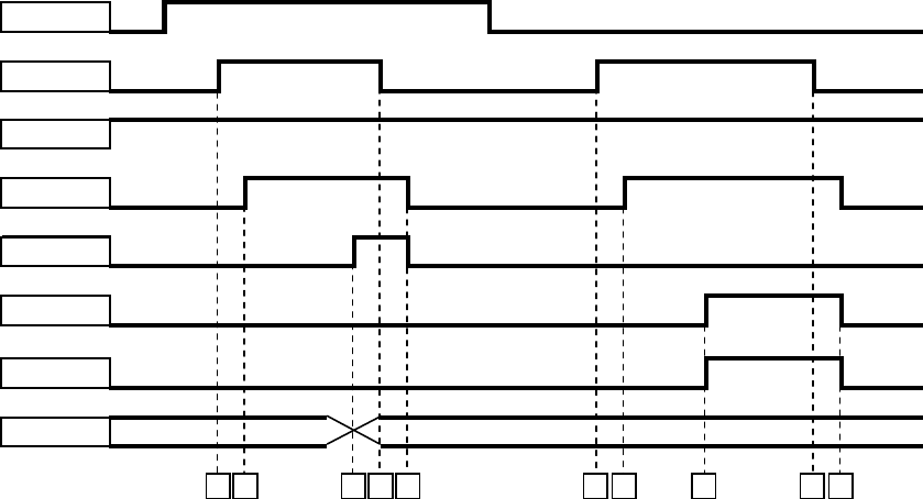
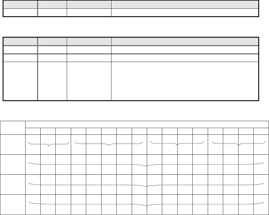
3.2. Timing chart
ID tag
TRG
RUN
BUSY
NORM
ERR1
ERR_SUB
ID
A B C D E F G
ID tag in communication area
H I J
<When ID tag is in the communication area>
A:The plc makes TRG “1" (on) and directs the execution to FL REMOTE ID.
B:FL REMOTE ID fixes CMD (command), LEN (data length), and ADDR (start address), the communication
with the ID tag begins, and BUSY is “1" (on).
C:When the communication with the ID tag completed normally, FL REMOTE ID makes NORM "1" (on).
D:Please make TRG “0" (off) after the NORM signal turn to 1" (on).
E:BUSY and NORM when FL REMOTE ID confirms TRG is turned off.
<When ID tag is outside the communication area>
F:The plc makes TRG “1" (on) and directs the execution to FL REMOTE ID.
G:FL REMOTE ID fixes CMD (command), LEN (data length), and ADDR (start address), the communication
with the ID tag begins, and BUSY is “1" (on).
H:When the communication with the ID tag did not complete normally, FL REMOTE ID makes ERR1 and
ERR_SUB0. I:Please make TRG “0" (off) after the ERR1 signal turn to 1" (on).
J:ERR1 and ERR_SUB0 when FL REMOTE ID confirms TRG is turned off.

4. Appendix
4.1. Specifications
- FL REMOTE ID V680-HAM42-FRT
Characteristic Specification
Supply voltage 24VDC(20.4VDC to 26.4VDC)
Protective conductor
Power consumption Less than 6W
Ambient temperature Operating:-10 to +55℃, storage: -25 to +65℃
(no freezing, no dew condensation)
Ambient humidity Operating: 35 to 85%RH, storage: 35 to 85%RH
(no freezing, no dew condensation)
Insulation resistance 20MΩmin. (with 500V DC megger)
between protective terminal and other charging unit terminal
Withstand voltage 1000V AC, 50/60Hz, 1min
Between protective terminal and other charging unit terminal
Vibration resistance Mechanical durability: 10 to 150Hz, double amplitude: 0.2mm,
with 10 sweep of 8 min each in 3 directions
Shock resistance Mechanical durability: 150m/s2, 3times each in 6 directions
Degree of protection Panel-mounting (conforms to IP20)
Material PC/ABS resin
Weight Approx. 150g
Mounting method DIN Track or M4 screws
- Antenna V680-HS63-SP
Characteristic Specification
Ambient temperature Operating:-10 to +60℃, storage: -25 to +75℃
(no freezing, no dew condensation)
Ambient humidity Operating: 35 to 95%RH, storage: 35 to 95%RH
(no freezing, no dew condensation)
Insulation resistance 20MΩmin. (with 500V DC megger)
between the connector and the case
Withstand voltage 1000V AC, 50/60Hz, 1min
Between the connector and the case
Vibration resistance Mechanical durability: 10 to 500Hz, double amplitude: 1.5mm,
with 10 sweep of 8 min each in 3 directions
Shock resistance Mechanical durability: 500m/s2, 3times each in 6 directions
Degree of protection IP67(* The connector is not waterproof.)
Material CASE PFA
Filler Epoxy resin
Cable TFE
Weight Approx. 20g
Mounting method M4 screws

- ID Tag V680-D1KP66T-SP
Characteristic Specification
Memory capacity 1,000 bytes (user area)
Memory type EEPROM
Data backup time 10 years after writing (85℃ or less)
Data overwrite count 100,000 times per address (25℃)
Ambient temperature Operating:-25 to +70℃, storage: -40 to +110℃
(no freezing, no dew condensation)
Ambient humidity Operating: 35 to 95%RH, storage: 35 to 95%RH
(no freezing, no dew condensation)
Vibration resistance Mechanical durability: 10 to 2,000Hz, double amplitude: 1.5mm,
with 10 sweep of 15 min each in 3 directions
Shock resistance Mechanical durability: 500m/s2, 3times each in 6 directions
Degree of protection IP67(* The connector is not waterproof.)
Material PFA
Weight Approx. 20g
Mounting method M4 screws
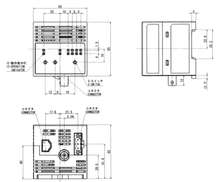
4.2. Dimensions
- FL REMOTE ID V680-HAM42-FRT
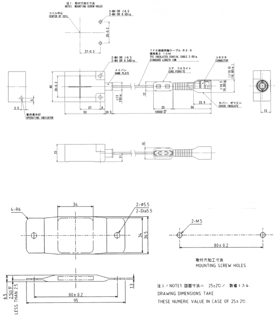
- Antenna V680-HS63-SP
- ID tag V680-D1KP66T-SP