Omron V78068 RFID READER/WRITER User Manual sec7
Omron Corporation RFID READER/WRITER sec7
UserManual.wiki
>
Omron
>
V78068 User Manual
>
Users manual-2
Contents
1.
Users manual-1
2.
Users manual-2
Users manual-2
Navigation menu
Upload a User Manual
Namespaces
Wiki Guide
HTML
PDF
Info
Views
User Manual
Discussion / Help
Navigation
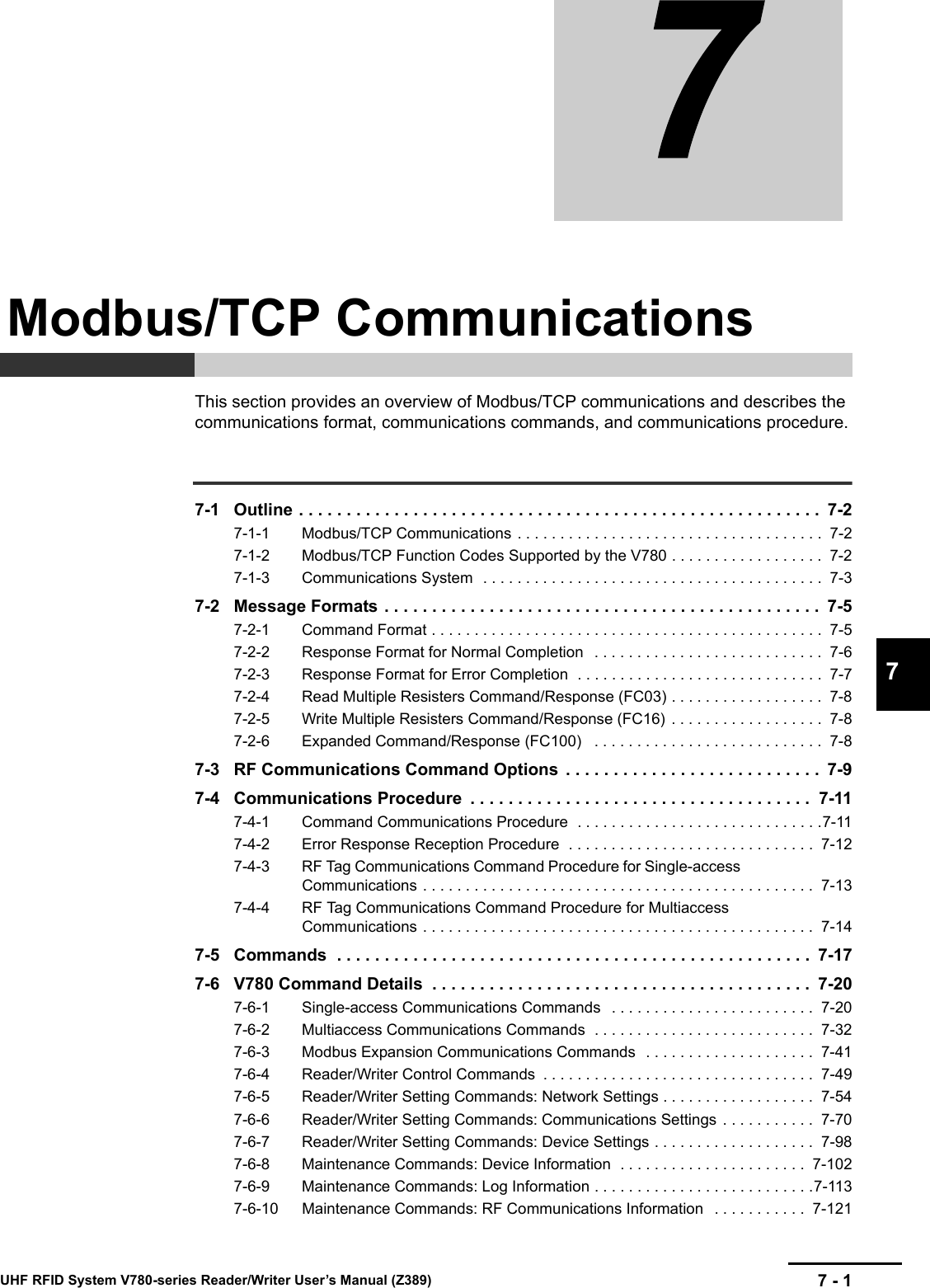

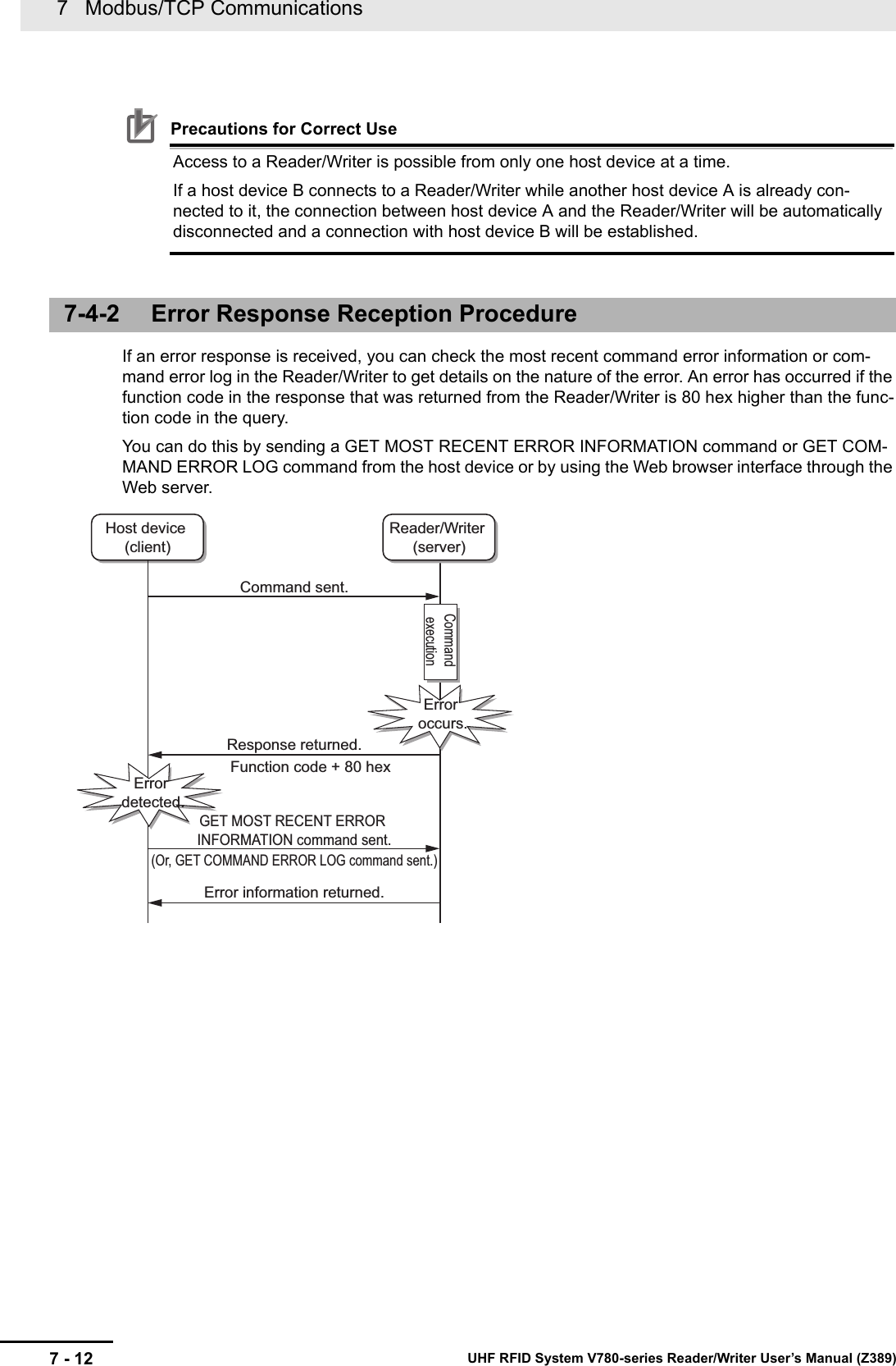
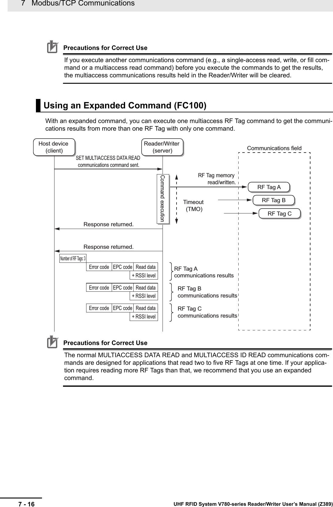
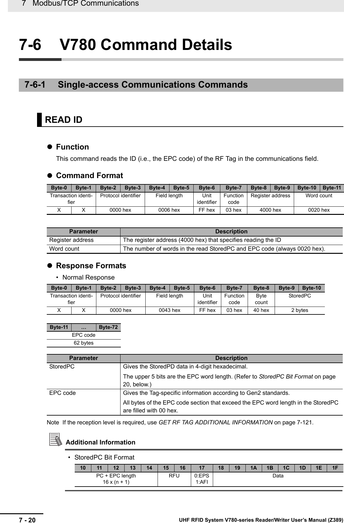
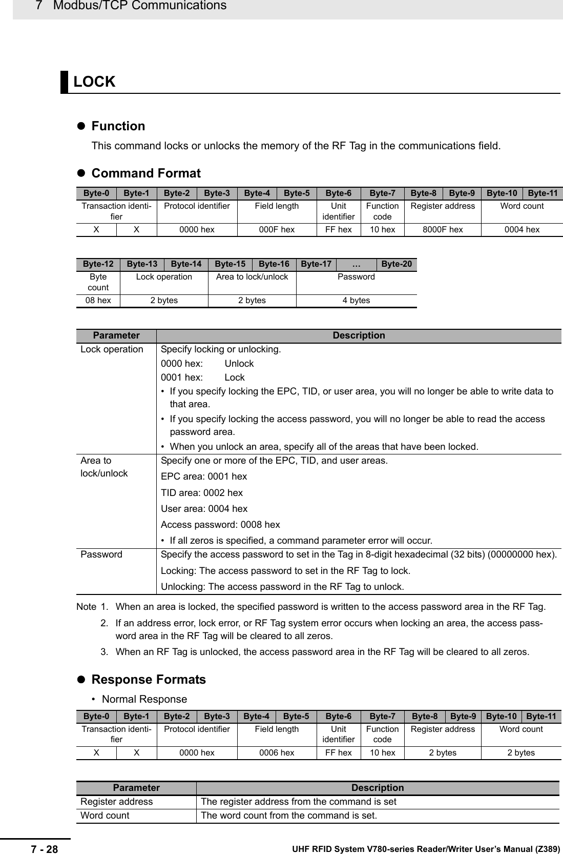
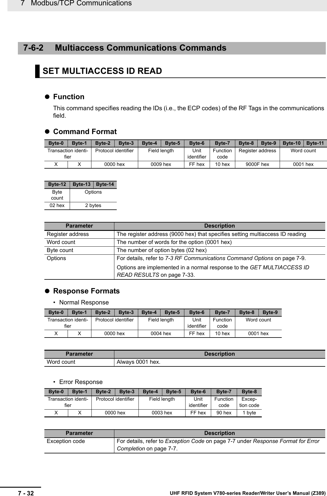
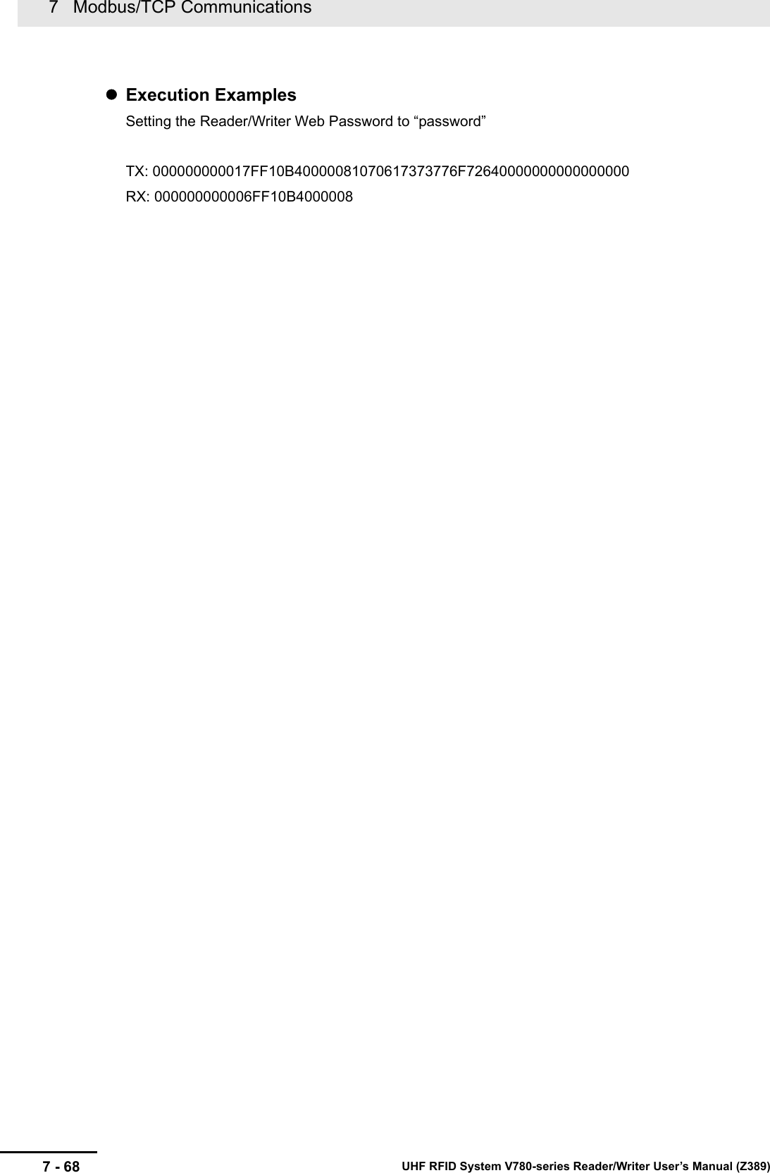
![7 - 97 Modbus/TCP CommunicationsUHF RFID System V780-series Reader/Writer User’s Manual (Z389)7-3 RF Communications Command Options77-3 RF Communications Command OptionsThis section describes the options that you can use together with RF communications commands (mul-tiaccess or Modbus expansion). You can specify options to get the EPC of the RF Tag, the reception level, or other communications information together with the normal data for the command.For commands with the multiaccess specification, the communications information specified with the option is returned in the response for the command that gets the execution results, i.e., the two com-mands are used together.For commands with the Modbus expansion, the communications information specified with the option is returned as an attachment to the response.OptionsOption Specification Examples:Specify 0001 hex to have the EPC attached.Specify 0003 hex to have the EPC and reception level attached.Specify 0011 hex to have the EPC and diagnostic results attached.Options Supported by RF Communications CommandsOK: Option can be specified, No: Option cannot be specified. (A parameter error will occur if it is.) ---: Reserved (Always specify 0 for these unused bits.)OptionsItem Relevant bit Description Information sizeEPC Bit 0 The StoredPC and EPC code are attached. 32 wordsReception levelBit 1 The reception level (signed hexadecimal) is attached.FFFF to FF9D hex (-1 to -99 [dBm])• A value of 0 will be set if processing ended in an error.1 wordReserved 1 Bits 2 to 3 • These bits are reserved. ---Diagnostic resultBit 4 The diagnostic results (4-digit hexadecimal) are attached.If communications diagnostics are disabled, 0000 hex is attached.For details, refer to Response Formats on page 7-125 under GET COMMUNICATIONS DIAGNOSTIC INFORMATION on page 7-125.1 wordReserved 2 Bits 5 to 15 • These bits are reserved. ---Classification CommandOptionsReservedDiag-nostic resultsReserved RSSI EPCBits 5 to 15 Bit 4 Bits 2 and 3 Bit 1 Bit 0Communications command, multi-accessSET MULTIACCESS ID READ --- No --- OK NoSET MULTIACCESS DATA READ --- No --- OK OK](https://usermanual.wiki/Omron/V78068.Users-manual-2/User-Guide-3305498-Page-9.png)


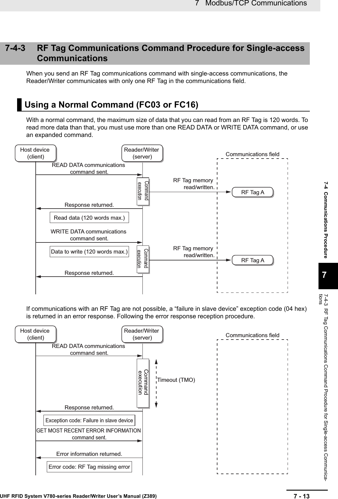
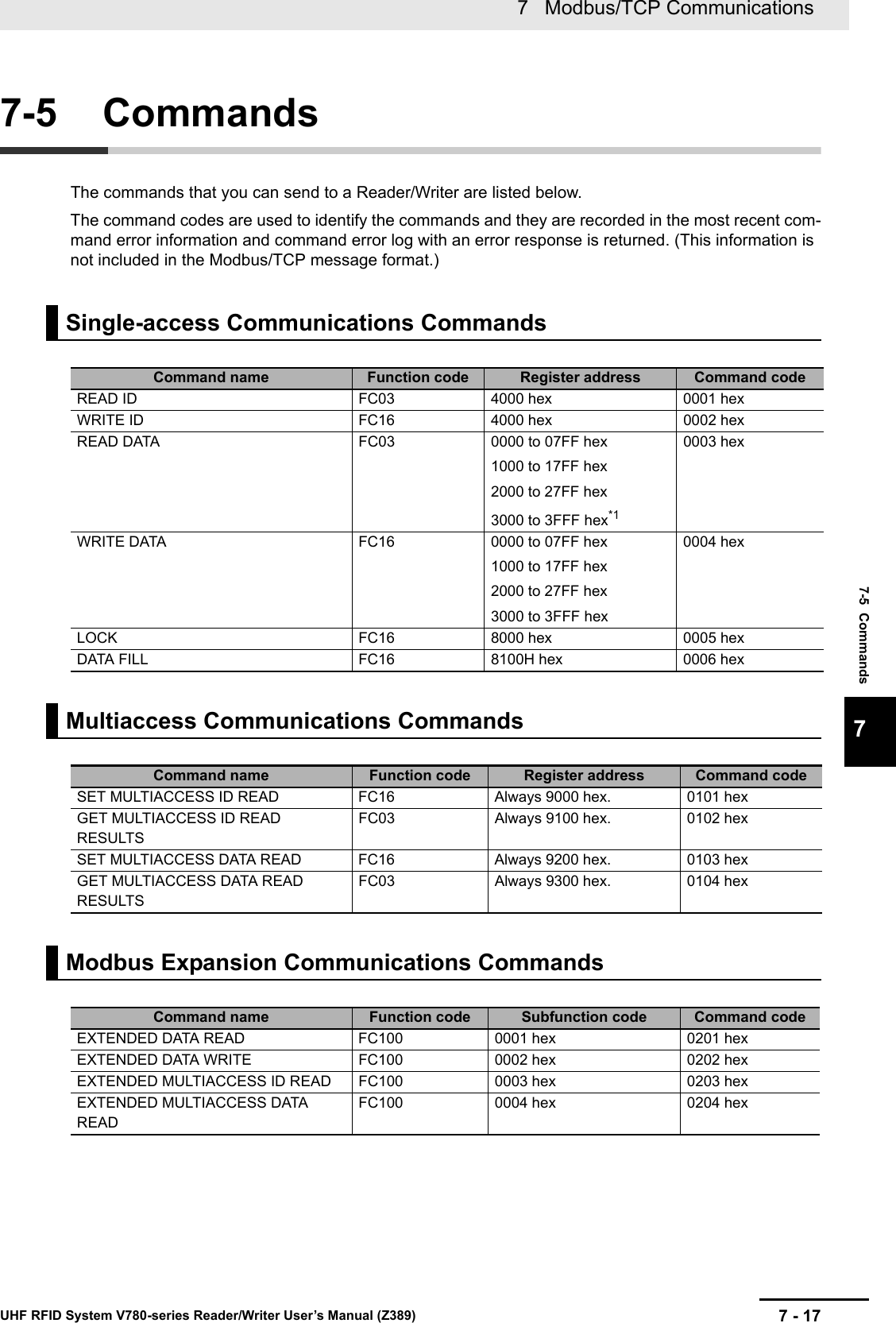
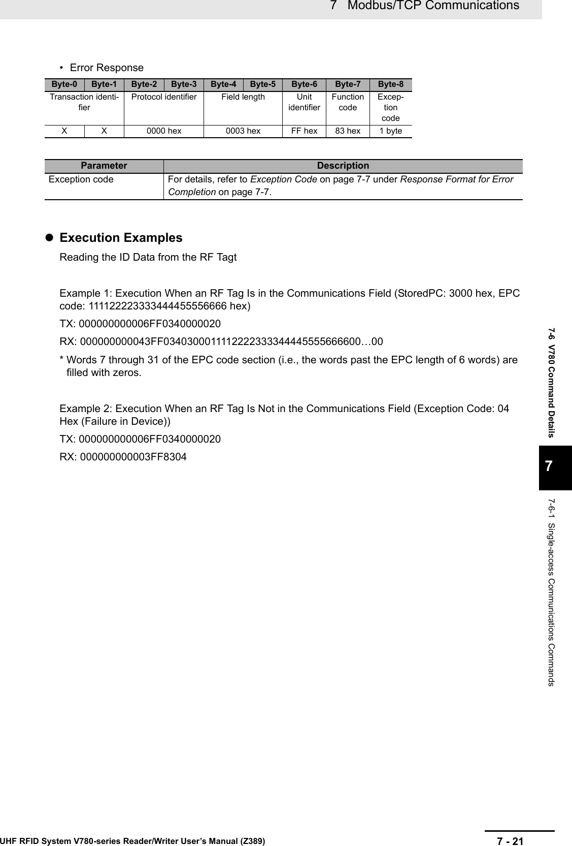
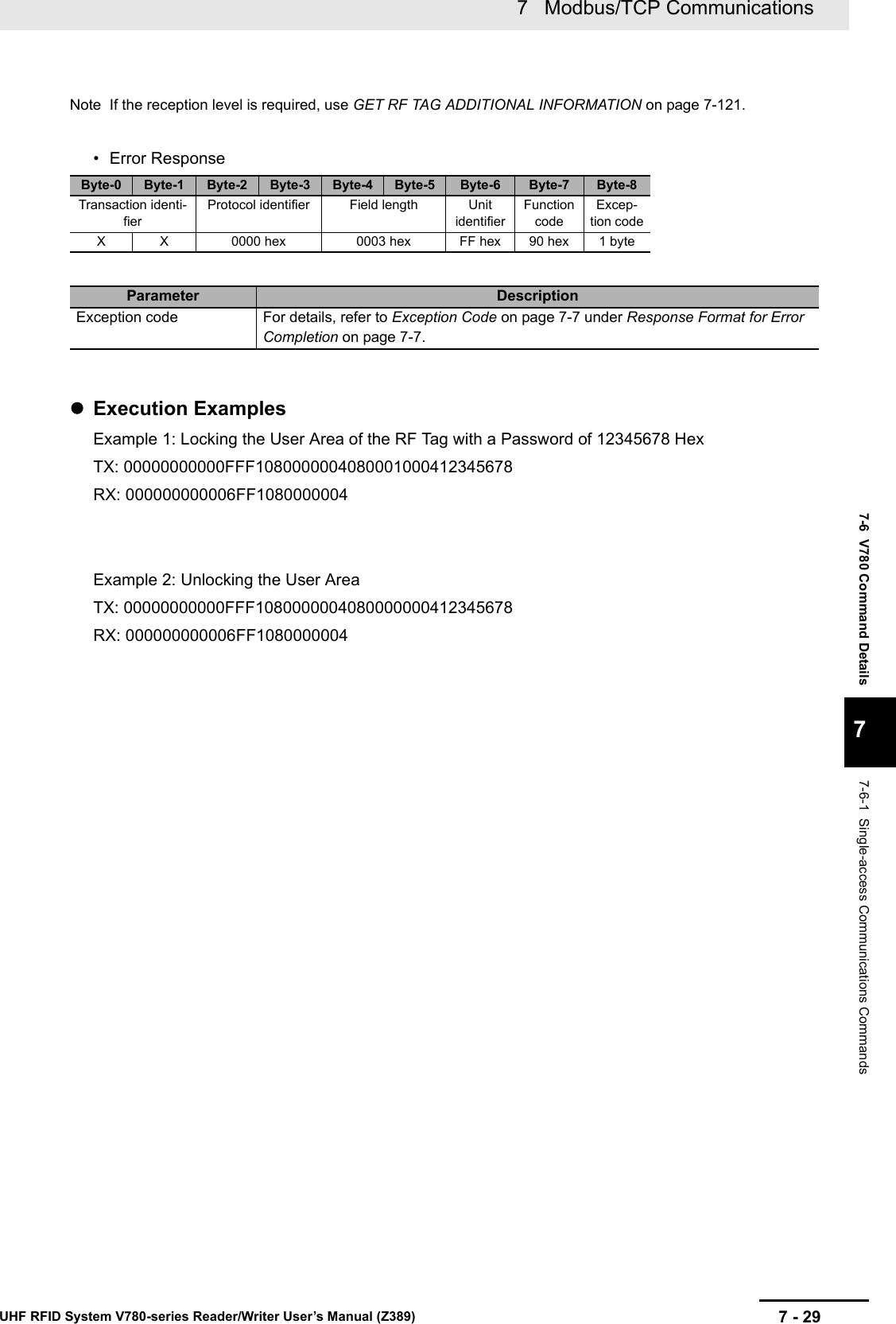
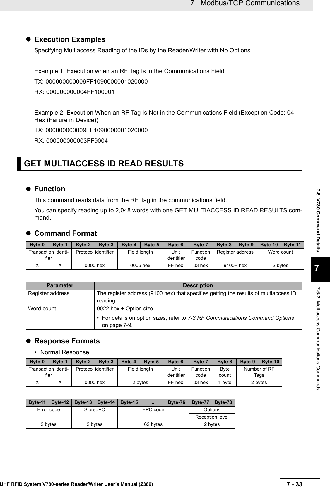
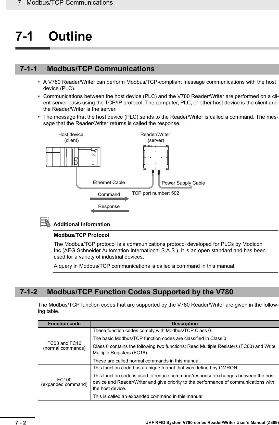
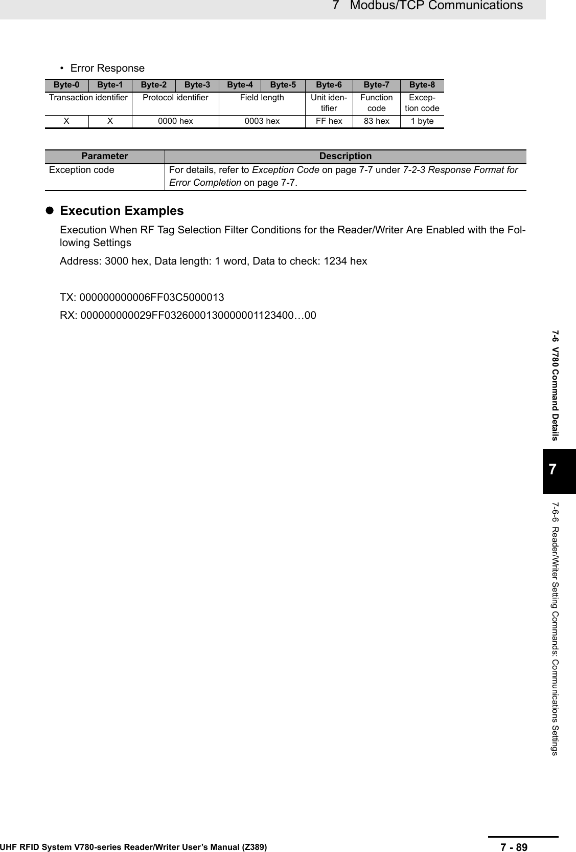
![7 Modbus/TCP Communications7 - 34 UHF RFID System V780-series Reader/Writer User’s Manual (Z389)• Error ResponseExecution ExamplesSpecifying Getting the Results of Multiaccess Reading of the IDs by the Reader/Writer with No OptionsThere are three RF Tags in the communications field. Getting the First Results (Getting the Communications Results for RF Tag A)TX: 000000000006FF0391000022RX: 000000000047FF0344000300003000AAAA…AAAA0000…0000Parameter DescriptionField length Gives the total number of bytes starting from the unit identifier in 4-digit hexadecimal.0047 hex + Option size• For details on option sizes, refer to 7-3 RF Communications Command Options on page 7-9.Byte count Gives the total number of bytes starting from the number of RF Tags in 2-digit hexadecimal.44 hex + Option size• For details on option sizes, refer to 7-3 RF Communications Command Options on page 7-9.Number of RF Tags Gives the number of RF Tags that were read in 4-digit decimal. (0001 to 001F hex)The number of RF Tags is decremented when a command response is returned.Error code Gives the RF Tag access results in 4-digit hexadecimal.0000 hex: Normal endNot 0000 hex: Error code• For details on the error codes, refer to ?9-2-1 ?????? (P.9-3)?.StoredPC Gives the StoredPC data in 4-digit hexadecimal.The upper 5 bits are the EPC word length.EPC code Gives the Tag-specific information according to Gen2 standards.All bytes of the EPC code section that exceed the EPC word length in the StoredPC are filled with 00 hex.Options This section may be omitted depending on the option value for the SET MULTIACCESS ID READ command.Reception level The reception level is attached in signed 4-digit hexadecimal.FFFF to FF9D hex (−1 to -99 [dBm])Byte-0 Byte-1 Byte-2 Byte-3 Byte-4 Byte-5 Byte-6 Byte-7 Byte-8Transaction identi-fierProtocol identifier Field length Unit identifierFunction codeExcep-tion codeX X 0000 hex 0003 hex FF hex 83 hex 1 byteParameter DescriptionException code For details, refer to Exception Code on page 7-7 under Response Format for Error Completion on page 7-7.](https://usermanual.wiki/Omron/V78068.Users-manual-2/User-Guide-3305498-Page-34.png)
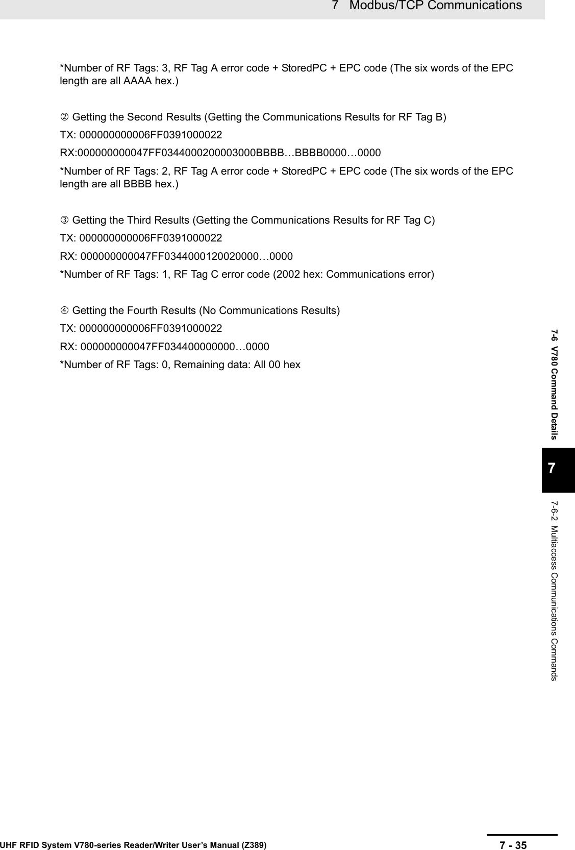
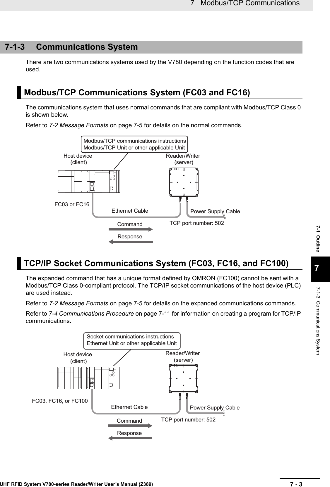
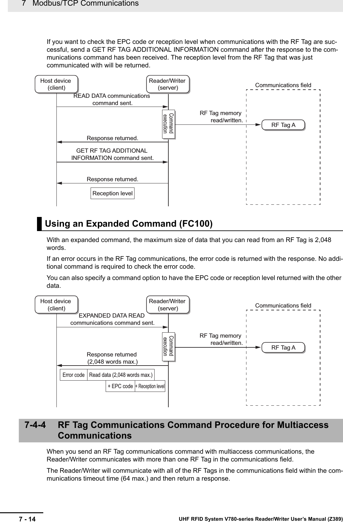
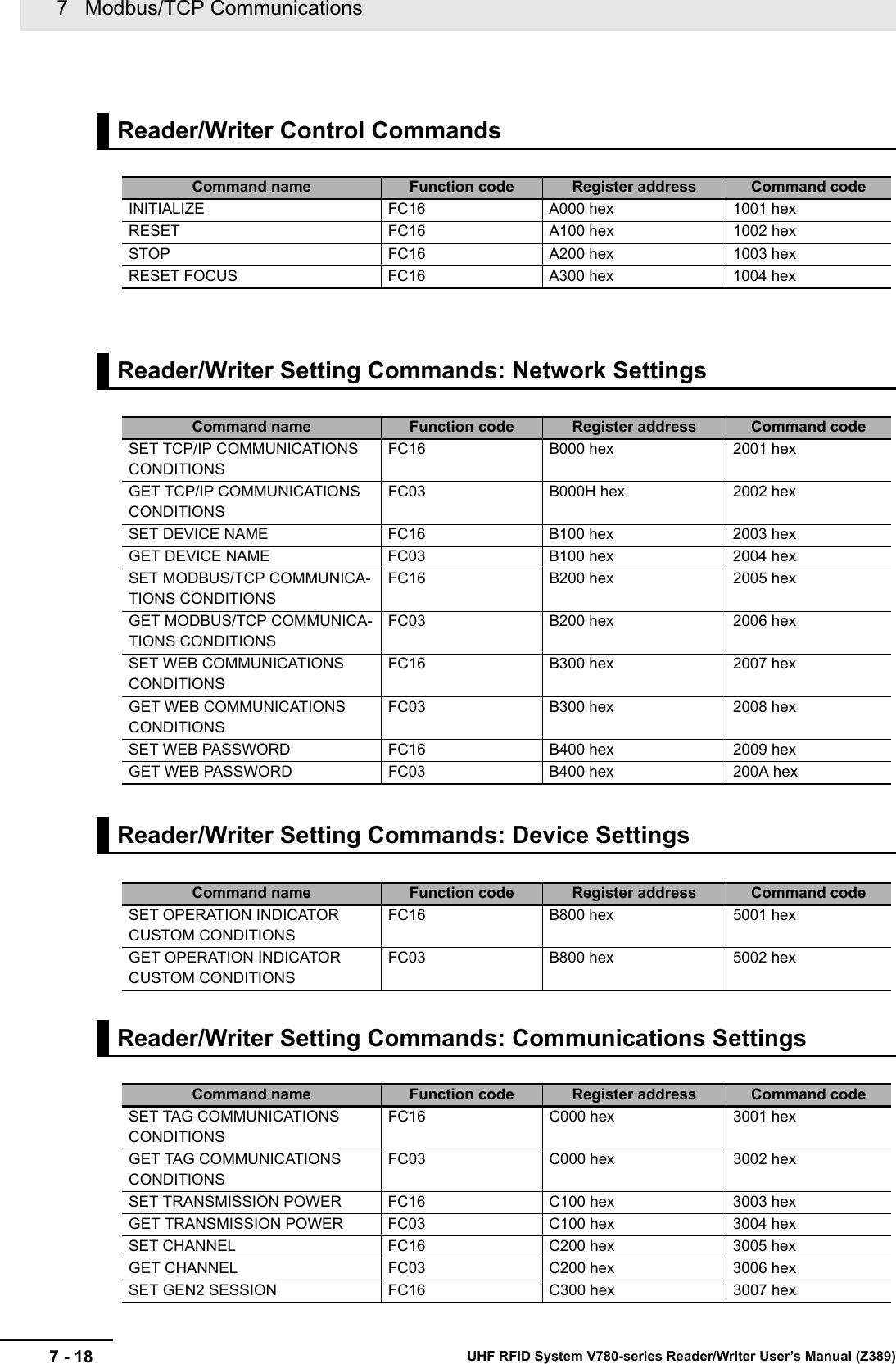
![7 - 397 Modbus/TCP CommunicationsUHF RFID System V780-series Reader/Writer User’s Manual (Z389)7-6 V780 Command Details77-6-2 Multiaccess Communications Commands• Error ResponseByte count Gives the total number of bytes starting from the number of RF Tags in 2-digit hexadecimal.06 to 44 hex + Option size• For details on option sizes, refer to 7-3 RF Communications Command Options on page 7-9.Number of RF Tags Gives the number of RF Tags that were read in 4-digit decimal. (0001 to 001F hex)The number of RF Tags is decremented when a command response is returned.Error code Gives the RF Tag access results in 4-digit hexadecimal.0000 hex: Normal endNot 0000 hex: Error code• For details on the error codes, refer to ?9-2-1 ?????? (P.9-3)?.Read data The data that was read from the RF Tag is attached.Options This section may be omitted depending on the option value for the SET MULTI-ACCESS ID READ command.StoredPC Gives the StoredPC data in 4-digit hexadecimal.The upper 5 bits are the EPC word length.EPC code Gives the Tag-specific information according to Gen2 standards.All bytes of the EPC code section that exceed the EPC word length in the StoredPC are filled with 00 hex.Reception level The reception level is attached in signed 4-digit hexadecimal.FFFF to FF9D hex (-1 to -99 [dBm])Byte-0 Byte-1 Byte-2 Byte-3 Byte-4 Byte-5 Byte-6 Byte-7 Byte-8Transaction identi-fierProtocol identifier Field length Unit identifierFunction codeExcep-tion codeX X 0000 hex 0003 hex FF hex 83 hex 1 byteParameter DescriptionException code For details, refer to Exception Code on page 7-7 under Response Format for Error Completion on page 7-7.Parameter Description](https://usermanual.wiki/Omron/V78068.Users-manual-2/User-Guide-3305498-Page-39.png)
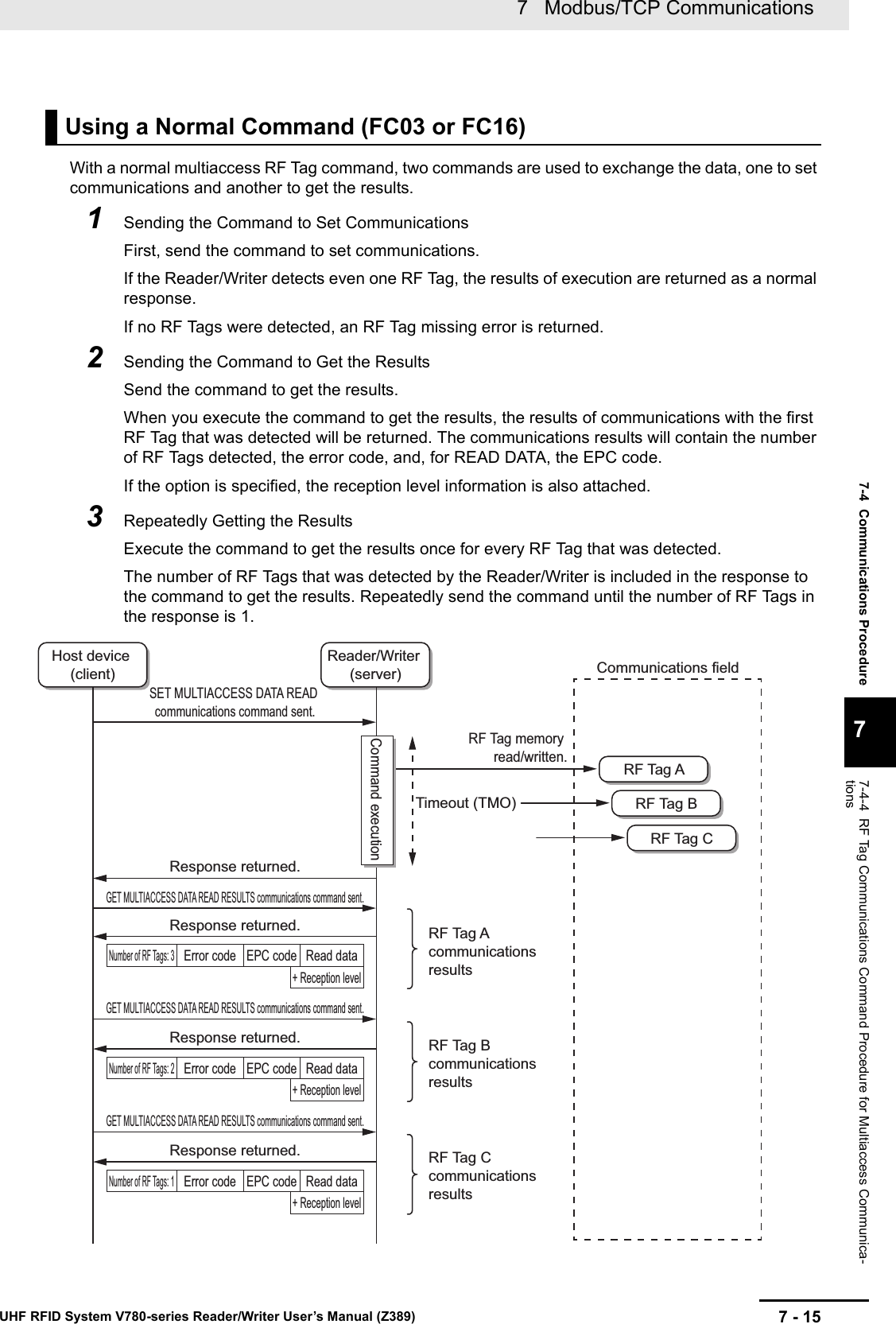
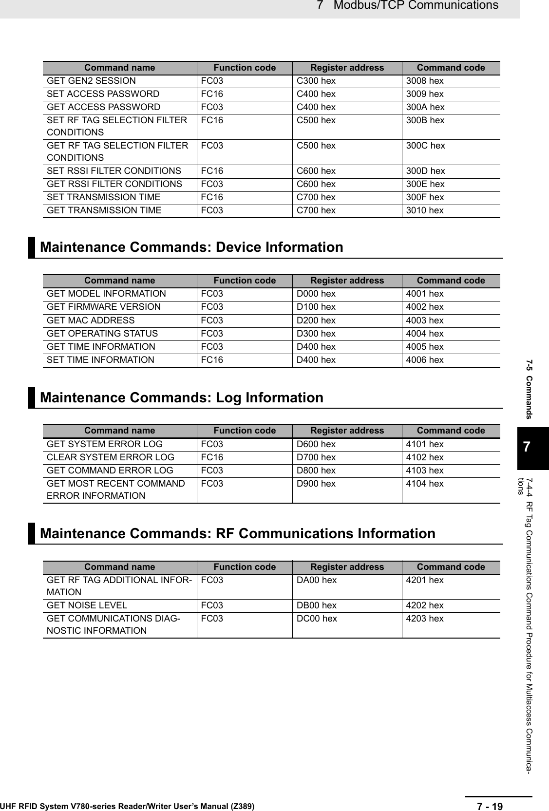
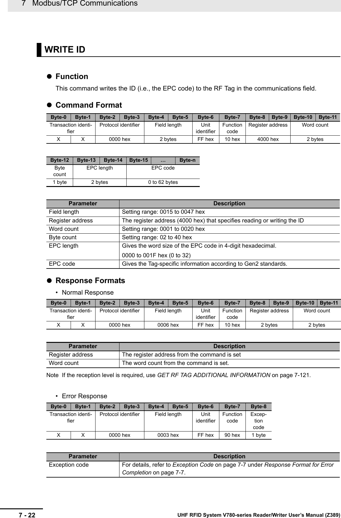
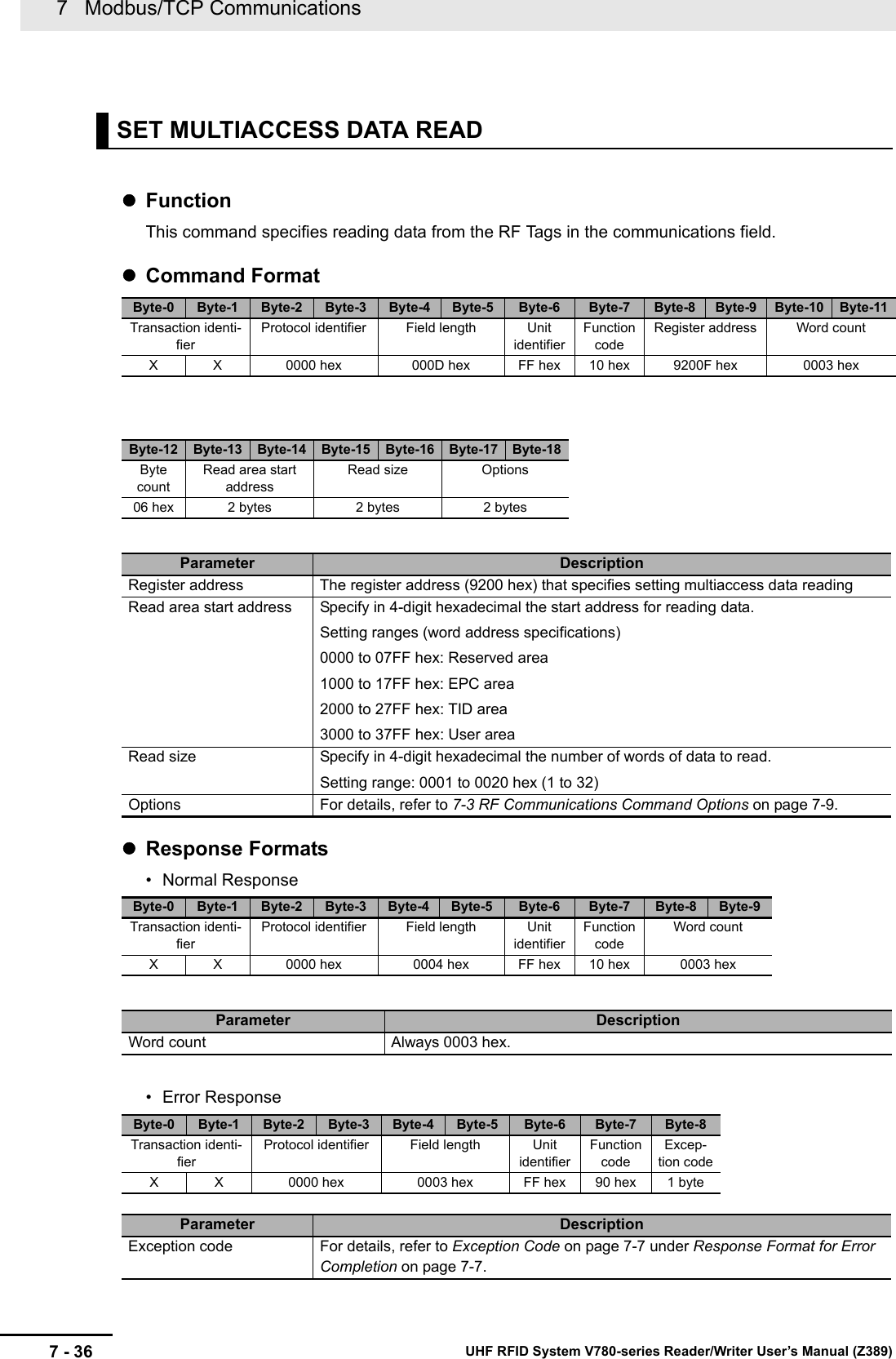
![7 Modbus/TCP Communications7 - 42 UHF RFID System V780-series Reader/Writer User’s Manual (Z389)• Error Response: RF Tag Communications Error • Error Response: Command ErrorExecution ExamplesReading 2,048 Words of Data Starting from Word Address 0000 Hex (User Area) in the RF Tag with No OptionsExample 1: Execution When an RF Tag Is Not in the Communications Field (Read Data: 1111222233334444…FFFF Hex)TX: 00000000000AFF640001300008000000RX: 000000000806FF64000100001111222233334444…FFFFExample 2: Execution When an RF Tag Is Not in the Communications Field (Error Code: 2001 Hex (RF Tag Missing Error))TX: 00000000000AFF640001300008000000RX: 000000000006FF6400012001Parameter DescriptionField length 0008 to 1006 hex + Option size• For details on option sizes, refer to 7-3 RF Communications Command Options on page 7-9.Read data The data that was read from the RF Tag is attached. (Range: 0001 to 0800 hex, in words)Options These parameters may be omitted depending on the option value.StoredPC Gives the StoredPC data in 4-digit hexadecimal.The upper 5 bits are the EPC word length.EPC code Gives the Tag-specific information according to Gen2 standards.All bytes of the EPC code section that exceed the EPC word length in the StoredPC are filled with 00 hex.Reception level The reception level is attached in signed 4-digit hexadecimal.FFFF to FF9D hex (-1 to -99 [dBm])Diagnostic resultsGives the diagnostic results in 4-digit hexadecimal.For details, refer to Response Formats on page 7-125 under NTLPxREF Communications Diagnostic Information.Byte-0 Byte-1 Byte-2 Byte-3 Byte-4 Byte-5 Byte-6 Byte-7 Byte-8 Byte-9 Byte-10 Byte-11Transaction iden-tifierProtocol identifier Field length Unit identifierFunc-tion codeSubfunction code Error codeX X 0000 hex 0006 hex FF hex 64 hex 0001 hex 2 bytesParameter DescriptionError code For details, refer to ?9-2-1 ?????? (P.9-3)?.Byte-0 Byte-1 Byte-2 Byte-3 Byte-4 Byte-5 Byte-6 Byte-7 Byte-8Transaction identi-fierProtocol identifier Field length Unit iden-tifierFunction codeExcep-tion codeX X 0000 hex 0003 hex FF hex E5 hex 1 byteParameter DescriptionException code For details, refer to Exception Code on page 7-7 under Response Format for Error Completion on page 7-7.](https://usermanual.wiki/Omron/V78068.Users-manual-2/User-Guide-3305498-Page-42.png)
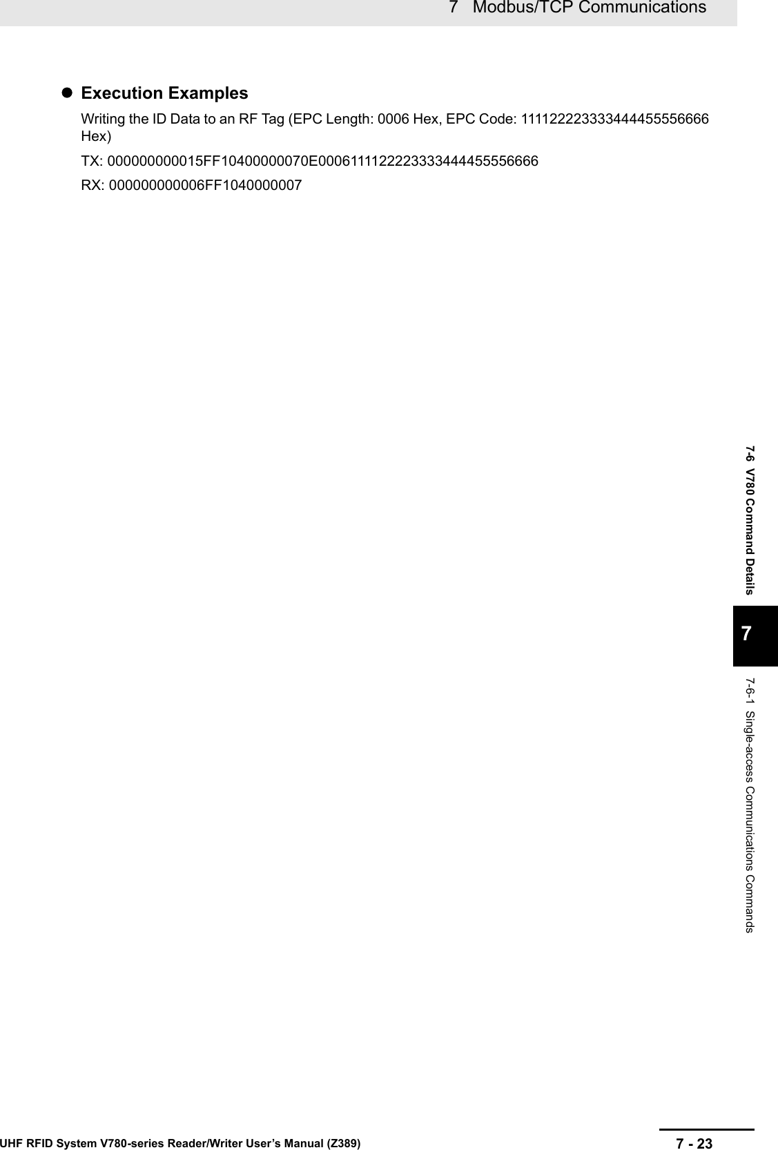
![7 Modbus/TCP Communications7 - 44 UHF RFID System V780-series Reader/Writer User’s Manual (Z389)• Error Response: RF Tag Communications Error • Error ResponseExecution ExamplesWriting 2,048 Words of Data Starting from Word Address 0000 Hex (User Area) in the RF Tag with No OptionsExample 1: Execution When an RF Tag Is Not in the Communications Field (Error Code: 0000 (Nor-mal Completion))TX: 00000000100AFF64000230001111222233334444…FFFF0000RX: 000000000006FF6600010000Example 2: Execution When an RF Tag Is Not in the Communications Field (Error Code: 2001 Hex (RF Tag Missing Error))TX: 00000000100AFF64000230001111222233334444…FFFF0000RX: 000000000006FF640002200Parameter DescriptionField length Normal completion: 0006 hex + Option size• For details on option sizes, refer to 7-3 RF Communications Command Options on page 7-9.Error code For details, refer to ?9-2-1 ?????? (P.9-3)?.Options These parameters may be omitted depending on the option value.StoredPC Gives the StoredPC data in 4-digit hexadecimal.The upper 5 bits are the EPC word length.EPC code Gives the Tag-specific information according to Gen2 standards.All bytes of the EPC code section that exceed the EPC word length in the StoredPC are filled with 00 hex.Reception level The reception level is attached in signed 4-digit hexadecimal.FFFF to FF9D hex (-1 to -99 [dBm])Diagnostic resultsGives the diagnostic results in 4-digit hexadecimal.For details, refer to Response Formats on page 7-125 under NTLPxREF Communications Diagnostic Information.Byte-0 Byte-1 Byte-2 Byte-3 Byte-4 Byte-5 Byte-6 Byte-7 Byte-8 Byte-9 Byte-10 Byte-11Transaction iden-tifierProtocol identifier Field length Unit identifierFunc-tion codeSubfunction code Error codeX X 0000 hex 0006 hex FF hex 64 hex 0002 hex 2 bytesParameter DescriptionError code For details, refer to N?9-2-1 ?????? (P.9-3)?.Byte-0 Byte-1 Byte-2 Byte-3 Byte-4 Byte-5 Byte-6 Byte-7 Byte-8Transaction identi-fierProtocol identifier Field length Unit identifierFunction codeExcep-tion codeX X 0000 hex 0003 hex FF hex E4 hex 1 byteParameter DescriptionException code For details, refer to Exception Code on page 7-7 under Response Format for Error Completion on page 7-7.](https://usermanual.wiki/Omron/V78068.Users-manual-2/User-Guide-3305498-Page-44.png)
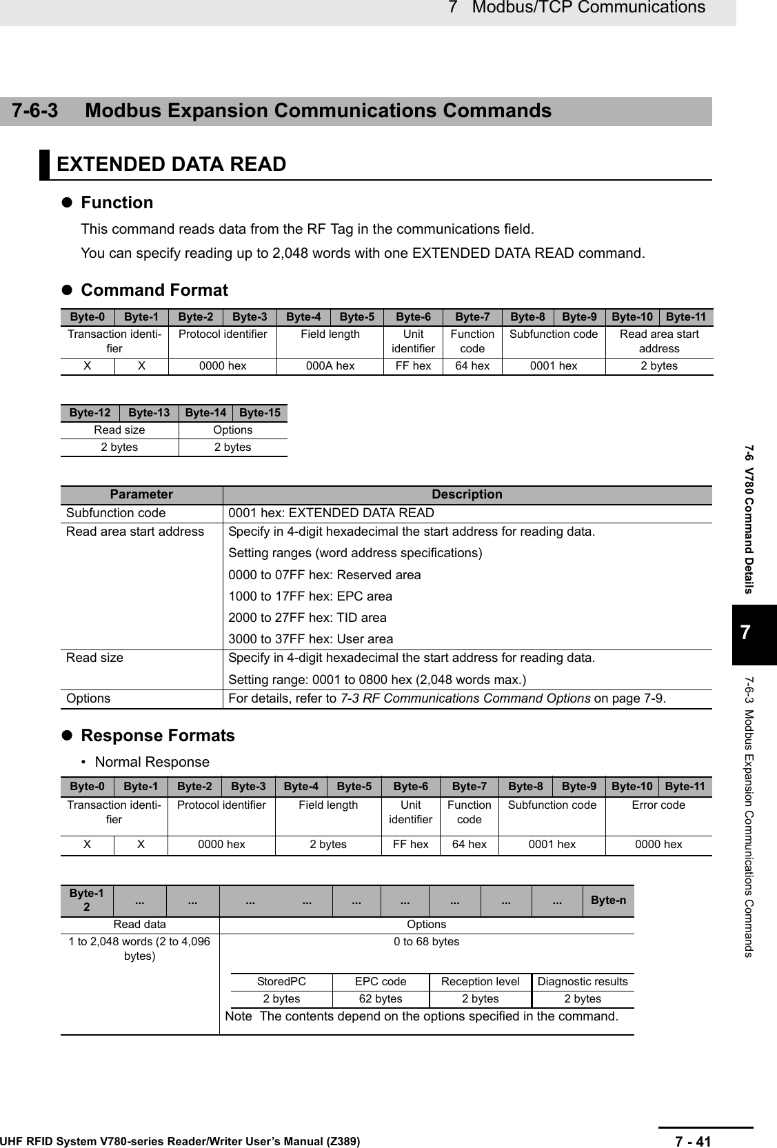
![7 - 457 Modbus/TCP CommunicationsUHF RFID System V780-series Reader/Writer User’s Manual (Z389)7-6 V780 Command Details77-6-3 Modbus Expansion Communications CommandsFunctionThis command reads the IDs (EPC codes) of multiple RF Tags in the communications field.You can get the IDs (EPC codes) of more than one RF Tag with one EXTENDED MULTIACCESS ID READ command.Command FormatResponse Formats• Normal Response or Error Response: RF Tag Communications ErrorEXTENDED MULTIACCESS ID READByte-0 Byte-1 Byte-2 Byte-3 Byte-4 Byte-5 Byte-6 Byte-7 Byte-8 Byte-9 Byte-10 Byte-11Transaction identi-fierProtocol identifier Field length Unit identifierFunction codeSubfunction code OptionsX X 0000 hex 0006 hex FF hex 64 hex 0003 hex 2 bytesParameter DescriptionSubfunction code 0003 hex: EXTENDED MULTIACCESS ID READOptions For details, refer to 7-3 RF Communications Command Options on page 7-9.Byte-0 Byte-1 Byte-2 Byte-3 Byte-4 Byte-5 Byte-6 Byte-7 Byte-8 Byte-9 Byte-10 Byte-11Transaction identi-fierProtocol identifier Field length Unit identifierFunction codeSubfunction code Number of RF Ta g s ( m)X X 0000 hex 2 bytes FF hex 64 hex 0003 hex 0000 to 0040 hexByte-12 ... Byte-12 + n - 1 ... Byte-12+n*(m-1) ... Byte-12+(n*m)-1Information from RF Tag 1 ... Information from RF Tag mn = 66 to 68 bytes ... n = 66 to 68 bytesInformation from RF Tag xError code StoredPC EPC code OptionsReception level2 bytes 2 bytes 62 bytes 2 bytesParameter DescriptionField length 0048 to 0F86 hex + (Option size × m)• For details on option sizes, refer to 7-3 RF Communications Command Options on page 7-9.Number of RF Tags Gives the number of RF Tags that were detected in 4-digit decimal.0000 to 0040 hex (0 to 64)Information from RF Tag 1Error code For details, refer to ?9-2-1 ?????? (P.9-3)?.StoredPC Gives the StoredPC data in 4-digit hexadecimal.The upper 5 bits are the EPC word length.EPC code Gives the Tag-specific information according to Gen2 standards.All bytes of the EPC code section that exceed the EPC word length in the StoredPC are filled with 00 hex.Options These parameters may be omitted depending on the option value.Recep-tion levelThe reception level is attached in signed 4-digit hexadecimal.FFFF to FF9D hex (-1 to -99 [dBm])](https://usermanual.wiki/Omron/V78068.Users-manual-2/User-Guide-3305498-Page-45.png)
![7 Modbus/TCP Communications7 - 48 UHF RFID System V780-series Reader/Writer User’s Manual (Z389)• Error ResponseNote If the exception code is 04 hex (failure in slave device), this format is not used and a response is returned.Execution ExamplesReading 4 Words of Data Starting from Word Address 0123 Hex (User Area) in Multiple RF Tags with No OptionsExample 1: Execution When Four RF Tags Are in the Communications FieldTX: 00000000000AFF640004312300040000RX: 00000000002EFF64000400040000AAAAAAAAAAAAAAAA: RF Tag A error code + Read data (4 words, all AAAA hex)0000BBBBBBBBBBBBBBBB: RF Tag B error code + Read data (4 words, all BBBB hex)0000CCCCCCCCCCCCCCCC: RF Tag C error code + Read data (4 words, all CCCC hex)2002000000000000000000: RF Tag D error code (2002 hex (communications error))Example 2: Execution When an RF Tag Is Not in the Communications Field (Exception Code: 04 Hex (Failure in Device))TX: 00000000000AFF640004312300040000RX: 000000000003FFE404Parameter DescriptionField length 000A to 2106 hex + (Option size × m)• For details on option sizes, refer to 7-3 RF Communications Command Options on page 7-9.Number of RF Tags Gives the number of RF Tags that were detected in 4-digit decimal.0000 to 0040 hex (0 to 64)Information from RF Tag 1Error code For details, refer to ?9-2-1 ?????? (P.9-3)?.Read data The data that was read from the RF Tag is attached.The bytes that exceed the word count will be filled with 00 hex.Options This section may be omitted depending on the option value for the SET MULTIACCESS ID READ command.StoredPCGives the StoredPC data in 4-digit hexadecimal.The upper 5 bits are the EPC word length.EPC codeGives the Tag-specific information according to Gen2 standards.All bytes of the EPC code section that exceed the EPC word length in the StoredPC are filled with 00 hex.Recep-tion levelThe reception level is attached in signed 4-digit hexadecimal.FFFF to FF9D hex (-1 to -99 [dBm])Byte-0 Byte-1 Byte-2 Byte-3 Byte-4 Byte-5 Byte-6 Byte-7 Byte-8Transaction identi-fierProtocol identifier Field length Unit identifierFunction codeExcep-tion codeX X 0000 hex 0003 hex FF hex E4 hex 1 byteParameter DescriptionException code For details, refer to Exception Code on page 7-7 under 7-2-3 Response Format for Error Completion on page 7-7.](https://usermanual.wiki/Omron/V78068.Users-manual-2/User-Guide-3305498-Page-48.png)


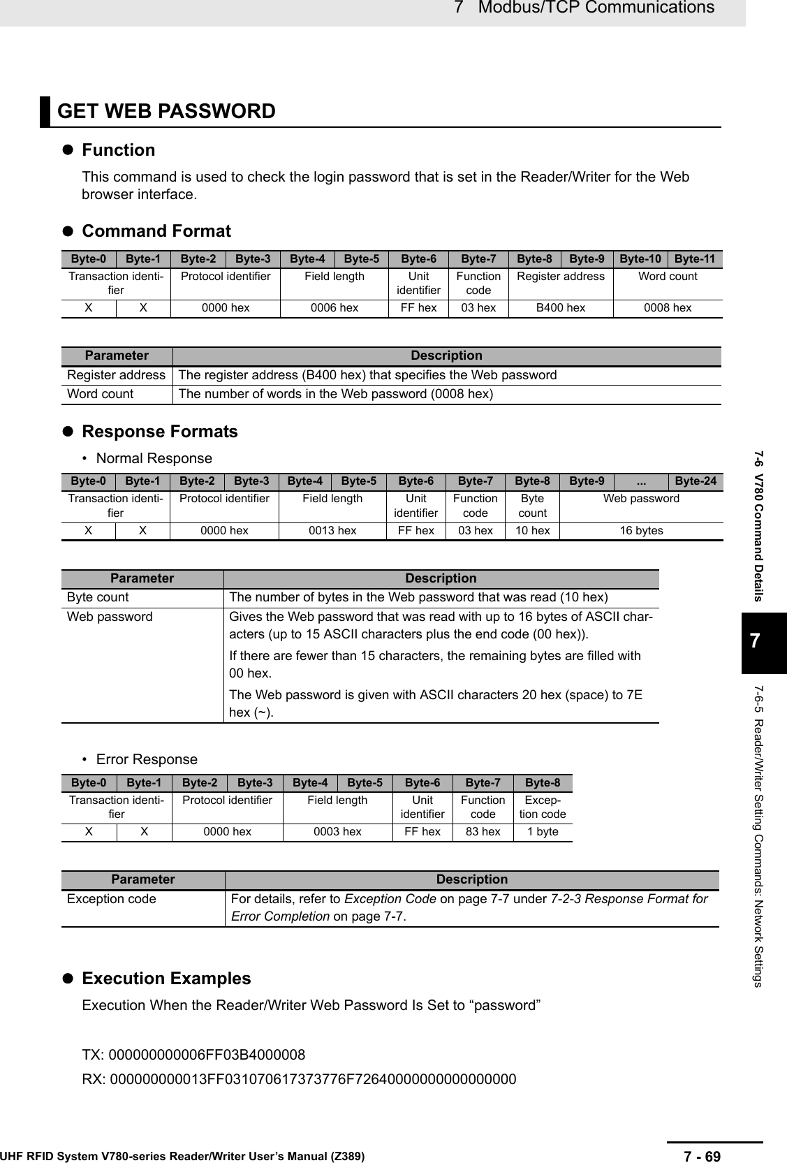
![7 Modbus/TCP Communications7 - 70 UHF RFID System V780-series Reader/Writer User’s Manual (Z389)FunctionThis command sets the communications conditions for the Reader/Writer.Command FormatResponse Formats• Normal Response7-6-6 Reader/Writer Setting Commands: Communications SettingsSET TAG COMMUNICATIONS CONDITIONSByte-0 Byte-1 Byte-2 Byte-3 Byte-4 Byte-5 Byte-6 Byte-7 Byte-8 Byte-9 Byte-10 Byte-11Transaction identi-fierProtocol identifier Field length Unit identifierFunction codeRegister address Word countX X 0000 hex 0011 hex FF hex 10 hex C000 hex 0005 hexByte-12 Byte-13 Byte-14 Byte-15 Byte-16 Byte-17 Byte-18 Byte-19 Byte-20 Byte-21 Byte-22Byte countCommunications conditions0A hex RF communica-tions modeRF communica-tions speedRF communica-tions timeout timeWrite verification Reserved2 bytes 2 bytes 2 bytes 2 bytes 0000 hexParameter Description Default settingRegister address The register address (C000 hex) that specifies the RF communications condi-tionsWord count The number of words in the RF communications conditions (0005 hex)Byte count The number of bytes in the RF communications conditions (0A hex)Commu-nica-tions condi-tionsRF communica-tions modeSpecify the communications mode in 4-digit hexadecimal.0000 hex: Once0001 hex: Auto0002 hex: Focus0000 hexRF communica-tions speedSpecify the communications speed in 4-digit hexadecimal.0000 hex: Automatic (default)0001 hex: High speed0002 hex: Normal speed0000 hexRF communica-tions timeout timeSpecify the RF communications timeout time.0001 to EA60 hex (1 to 60,000 [ms])00FA hex(250)Write verification Specify in 4-digit hexadecimal whether to perform write veri-fication.0000 hex: Disable, 0001 hex: Enable0001 hexByte-0 Byte-1 Byte-2 Byte-3 Byte-4 Byte-5 Byte-6 Byte-7 Byte-8 Byte-9 Byte-10 Byte-11Transaction identi-fierProtocol identifier Field length Unit identifierFunction codeRegister address Word countX X 0000 hex 0006 hex FF hex 10 hex C000 hex 0005 hexParameter DescriptionRegister address The register address from the command is set.Word count The word count from the command is set.](https://usermanual.wiki/Omron/V78068.Users-manual-2/User-Guide-3305498-Page-70.png)
![7 Modbus/TCP Communications7 - 72 UHF RFID System V780-series Reader/Writer User’s Manual (Z389)FunctionThis command is used to check the RF communications conditions that are set in the Reader/Writer.Command FormatResponse Formats• Normal ResponseGET TAG COMMUNICATIONS CONDITIONSByte-0 Byte-1 Byte-2 Byte-3 Byte-4 Byte-5 Byte-6 Byte-7 Byte-8 Byte-9 Byte-10 Byte-11Transaction identi-fierProtocol identifier Field length Unit identifierFunction codeRegister address Word countX X 0000 hex 0006 hex FF hex 03 hex C000 hex 0005 hexParameter DescriptionRegister address The register address (C000 hex) that specifies the RF communications conditionsWord count The number of words of the RF communications conditions to read (0005 hex)Byte-0 Byte-1 Byte-2 Byte-3 Byte-4 Byte-5 Byte-6 Byte-7 Byte-8Transaction identi-fierProtocol identifier Field length Unit identifierFunction codeByte countX X 0000 hex 000D hex FF hex 03 hex 0A hexByte-9 Byte-10 Byte-11 Byte-12 Byte-13Byte-14 Byte-15 Byte-16 Byte-17 Byte-18Communications conditionsRF communica-tions modeRF communica-tions speedRF communica-tions timeout timeWrite verification Reserved2 bytes 2 bytes 2 bytes 2 bytes 0000 hexParameter Description Default settingRegister address The register address (C000 hex) that specifies the RF communications conditionsWord count The number of words in the RF communications conditions (0005 hex)Byte count The number of bytes in the RF communications conditions (0A hex)Communica-tions conditionsRF communica-tions modeGives the communications mode in 4-digit hexadeci-mal.0000 hex: Once0001 hex: Auto0002 hex: Focus0000 hexRF communica-tions speedGives the communications speed in 4-digit hexadeci-mal.0000 hex: Automatic (default)0001 hex: High speed0002 hex: Normal speed0000 hexRF communica-tions timeout timeGives the RF communications timeout time.0001 to EA60 hex (1 to 60,000 [ms])00FA hex(250)Write verification Gives whether write verification is being performed in 4-digit hexadecimal.0000 hex: Disable, 0001 hex: Enable0001 hex](https://usermanual.wiki/Omron/V78068.Users-manual-2/User-Guide-3305498-Page-72.png)

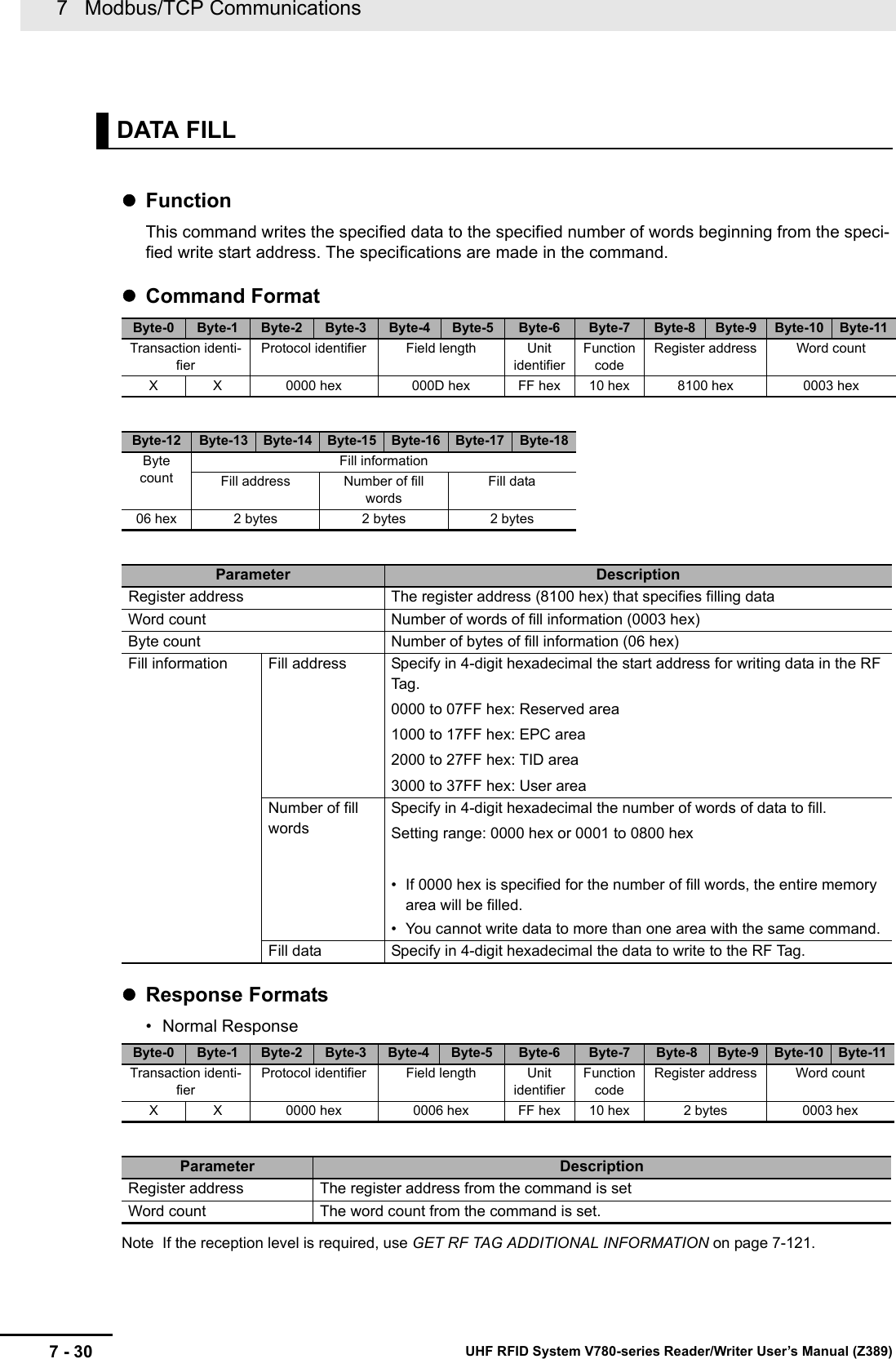
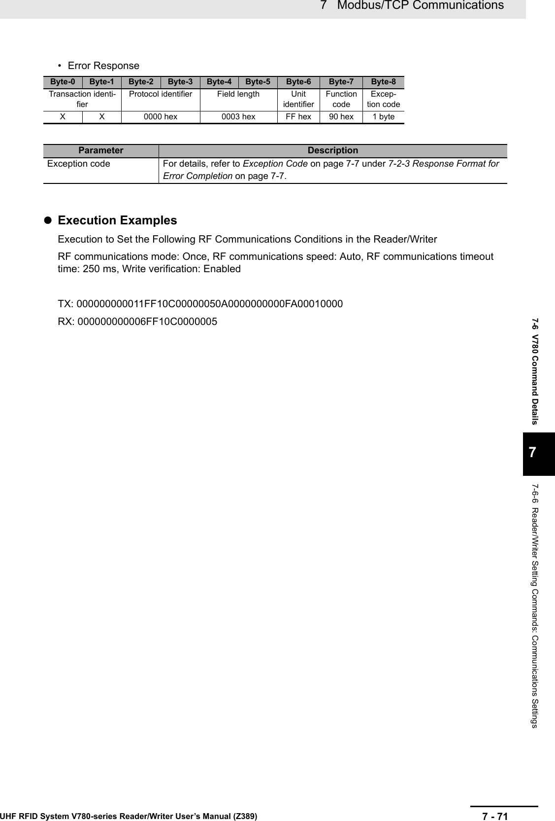
![7 Modbus/TCP Communications7 - 74 UHF RFID System V780-series Reader/Writer User’s Manual (Z389)FunctionThis command sets the transmission powers of the Reader/Writer.Command FormatResponse Formats• Normal Response• Error ResponseSET TRANSMISSION POWERByte-0 Byte-1 Byte-2 Byte-3 Byte-4 Byte-5 Byte-6 Byte-7 Byte-8 Byte-9 Byte-10 Byte-11Transaction identi-fierProtocol identifier Field length Unit identifierFunction codeRegister address Word countX X 0000 hex 000B hex FF hex 10 hex C100 hex 0002 hexByte-12 Byte-13 Byte-14 Byte-15 Byte-16Byte countTransmission power04 hex Read transmis-sion powerWrite transmis-sion power2 bytes 2 bytesParameter Description Default settingRegister address The register address (C100 hex) that specifies setting the transmission powersWord count The number of words in the transmission power settings (0002 hex)Byte count The number of bytes in the transmission power setting (04 hex)Transmission powerRead transmis-sion powerSpecify the transmission power for read RF communi-cations commands in 4-digit hexadecimal.000F to 001B hex (15 to 27 dBm)001B hex (27 [dBm])Write transmis-sion powerSpecify the transmission power for write RF communi-cations commands in 4-digit hexadecimal.000F to 001B hex (15 to 27 dBm)001B hex (27 [dBm])Byte-0 Byte-1 Byte-2 Byte-3 Byte-4 Byte-5 Byte-6 Byte-7 Byte-8 Byte-9 Byte-10 Byte-11Transaction identi-fierProtocol identifier Field length Unit identifierFunction codeRegister address Word countX X 0000 hex 0006 hex FF hex 10 hex C100 hex 0002 hexParameter DescriptionRegister address The register address from the command is set.Word count The word count from the command is set.Byte-0 Byte-1 Byte-2 Byte-3 Byte-4 Byte-5 Byte-6 Byte-7 Byte-8Transaction identi-fierProtocol identifier Field length Unit identifierFunction codeExcep-tion codeX X 0000 hex 0003 hex FF hex 90 hex 1 byteParameter DescriptionException code For details, refer to Exception Code on page 7-7 under 7-2-3 Response Format for Error Completion on page 7-7.](https://usermanual.wiki/Omron/V78068.Users-manual-2/User-Guide-3305498-Page-74.png)
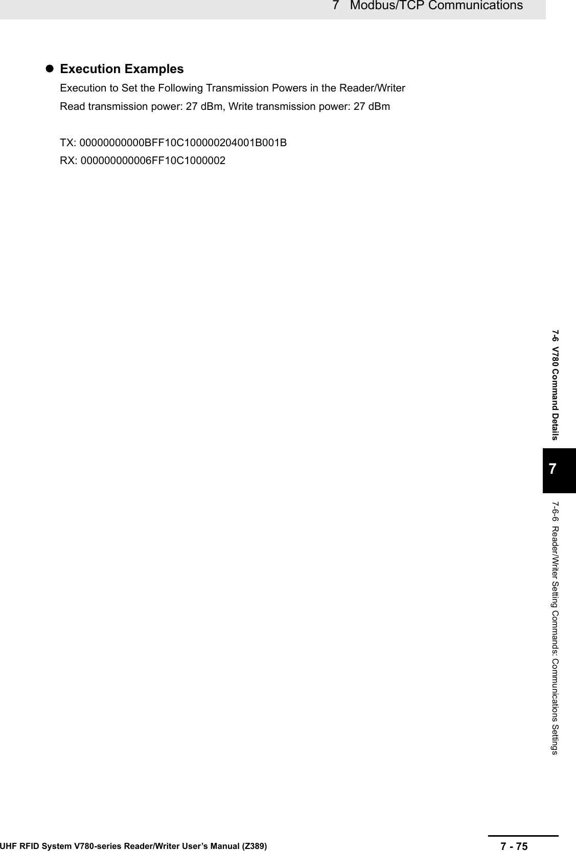
![7 Modbus/TCP Communications7 - 76 UHF RFID System V780-series Reader/Writer User’s Manual (Z389)FunctionThis command is used to check the transmission powers that are set in the Reader/Writer.Command FormatResponse Formats• Normal ResponseExecution ExamplesExecution When the Following RF Transmission Powers Are Set in the Reader/WriterRead transmission power: 27 dBm, Write transmission power: 27dBmTX: 000000000006FF03C1000002RX: 000000000007FF0304001B001BGET TRANSMISSION POWERByte-0 Byte-1 Byte-2 Byte-3 Byte-4 Byte-5 Byte-6 Byte-7 Byte-8 Byte-9 Byte-10 Byte-11Transaction identi-fierProtocol identifier Field length Unit identifierFunction codeRegister address Word countX X 0000 hex 0006 hex FF hex 03 hex C100 hex 0002 hexParameter DescriptionRegister address The register address (C100 hex) that specifies setting the transmission powerWord count The number of words of the antenna setting to read (0002 hex)Byte-0 Byte-1 Byte-2 Byte-3 Byte-4 Byte-5 Byte-6 Byte-7 Byte-8Transaction identi-fierProtocol identifier Field length Unit identifierFunction codeByte countX X 0000 hex 0007 hex FF hex 03 hex 04 hexByte-9 Byte-10 Byte-11 Byte-12Transmission powersRead transmis-sion powerWrite transmis-sion power2 bytes 2 bytesParameter Description Default settingByte count The number of bytes in the transmission powers (06 hex)Transmission powerRead transmis-sion powerGives the transmission power for read RF communica-tions commands in 4-digit hexadecimal.000F to 001B hex (15 to 27 dBm)001B hex(27 [dBm])Write transmis-sion powerGives the transmission power for write RF communica-tions commands in 4-digit hexadecimal.000F to 001B hex (15 to 27 dBm)001B hex(27 [dBm])](https://usermanual.wiki/Omron/V78068.Users-manual-2/User-Guide-3305498-Page-76.png)
![7 Modbus/TCP Communications7 - 90 UHF RFID System V780-series Reader/Writer User’s Manual (Z389)FunctionThis command sets the RSSI filter conditions for the Reader/Writer.Command FormatResponse Formats• Normal Response• Error ResponseSET RSSI FILTER CONDITIONSByte-0 Byte-1 Byte-2 Byte-3 Byte-4 Byte-5 Byte-6 Byte-7 Byte-8 Byte-9 Byte-10 Byte-11Transaction identi-fierProtocol identifier Field length Unit identifierFunction codeRegister address Word countX X 0000 hex 000D hex FF hex 10 hex C600 hex 0003 hexByte-12 Byte-13 Byte-14 Byte-15 Byte-16 Byte-17 Byte-18Byte countRSSI filter conditionsEnable/disable High threshold Low threshold06 hex 2 bytes 2 bytes 2 bytesParameter Description Default settingRegister address The register address (C600 hex) that specifies the RSSI filter conditionsWord count The number of words in the RSSI filter conditions (0003 hex)Byte count The number of bytes in the RSSI filter conditions (06 hex)RSSI filter conditionsEnable/disable Specify whether the RSSI filter is enabled or disabled in 4-digits hexadecimal.0000 hex: Disable0001 hex: Enable0000 hexHigh threshold*1*1. When you disable the RSSI filter conditions, set the high and low thresholds to 0000 hex. When you enable the RSSI filter, set the high threshold value for the reception level to a higher value than the low threshold level. Otherwise, a command parameter error will occur.Specify the high threshold for the reception level in signed 4-digit hexadecimal.FFF6 to FFBA hex (0 or -70 to -10) [dBm]0000 hexLow threshold*1 Specify the low threshold for the reception level in signed 4-digit hexadecimal.FFF6 to FFBA hex (0 or -70 to -10) [dBm]0000 hexByte-0 Byte-1 Byte-2 Byte-3 Byte-4 Byte-5 Byte-6 Byte-7 Byte-8 Byte-9 Byte-10 Byte-11Transaction identi-fierProtocol identifier Field length Unit identifierFunction codeRegister address Word countX X 0000 hex 0006 hex FF hex 10 hex C600 hex 0003 hexParameter DescriptionRegister address The register address from the command is set.Word count The word count from the command is set.Byte-0 Byte-1 Byte-2 Byte-3 Byte-4 Byte-5 Byte-6 Byte-7 Byte-8Transaction identifier Protocol identifier Field length Unit iden-tifierFunction codeExcep-tion codeX X 0000 hex 0003 hex FF hex 90 hex 1 byte](https://usermanual.wiki/Omron/V78068.Users-manual-2/User-Guide-3305498-Page-90.png)

![7 Modbus/TCP Communications7 - 92 UHF RFID System V780-series Reader/Writer User’s Manual (Z389)FunctionThis command is used to check the RSSI filter conditions that are set in the Reader/Writer.Command FormatResponse Formats• Normal Response*1. If the RSSI filter conditions are disabled, the high and low threshold levels will always be 0000 hex.• Error ResponseGET RSSI FILTER CONDITIONSByte-0 Byte-1 Byte-2 Byte-3 Byte-4 Byte-5 Byte-6 Byte-7 Byte-8 Byte-9 Byte-10 Byte-11Transaction identi-fierProtocol identifier Field length Unit identifierFunction codeRegister address Word countX X 0000 hex 0006 hex FF hex 03 hex C600 hex 0003 hexParameter DescriptionRegister address The register address (C600 hex) that specifies reading the RSSI filter conditionsWord count The number of words in the RSSI filter conditions to read (0003 hex)Byte-0 Byte-1 Byte-2 Byte-3 Byte-4 Byte-5 Byte-6 Byte-7 Byte-8Transaction identi-fierProtocol identifier Field length Unit identifierFunction codeByte countX X 0000 hex 0009 hex FF hex 03 hex 04 hexByte-9 Byte-10 Byte-11 Byte-12 Byte-13 Byte-14RSSI filter conditionsEnable/disable High threshold Low threshold2 bytes 2 bytes 2 bytesParameter Description Default settingByte count The number of bytes in the RSSI filter conditions (06 hex)RSSI filter conditionsEnable/dis-ableGives whether the RSSI filter is enabled or disabled in 4-dig-its hexadecimal.0000 hex: Disable0001 hex: Enable0000 hexHigh threshold*1Gives the RSSI high threshold level in signed 4-digit hexa-decimal.FFF6 to FFBA hex (0 or −70 to −10) [dBm]0000 hexLow threshold*1Gives the RSSI low threshold level in signed 4-digit hexa-decimal.FFF6 to FFBA hex (0 or −70 to −10) [dBm]0000 hexByte-0 Byte-1 Byte-2 Byte-3 Byte-4 Byte-5 Byte-6 Byte-7 Byte-8Transaction identifier Protocol identifier Field length Unit iden-tifierFunction codeExcep-tion codeX X 0000 hex 0003 hex FF hex 83 hex 1 byteParameter DescriptionException code For details, refer to Exception Code on page 7-7 under 7-2-3 Response Format for Error Completion on page 7-7.](https://usermanual.wiki/Omron/V78068.Users-manual-2/User-Guide-3305498-Page-92.png)

![7 Modbus/TCP Communications7 - 94 UHF RFID System V780-series Reader/Writer User’s Manual (Z389)FunctionThis command sets the time to stop the transmission power.Command Format*1. If you set a stop time, do not set the continuous transmission time to 0000 hex (unlimited). A command parameter error will occur if only the stop time or only the continuous transmission time is set to 0.Response Formats• Normal Response• Error ResponseSET TRANSMISSION TIMEByte-0 Byte-1 Byte-2 Byte-3 Byte-4 Byte-5 Byte-6 Byte-7 Byte-8 Byte-9 Byte-10 Byte-11Transaction identi-fierProtocol identifier Field length Unit identifierFunction codeRegister address Word countX X 0000 hex 000B hex FF hex 10 hex C700 hex 0002 hexByte-12 Byte-13 Byte-14 Byte-15 Byte-16Byte countStop time Continuous trans-mission time04 hex 2 bytes 2 bytesParameter Description Default settingRegister address The register address (C700 hex) that specifies setting the transmission timesWord count The number of words in the transmission time setting (0002 hex)Byte count The number of bytes in the transmission time setting (04 hex)Stop time*1Specify the time to stop the output during RF communications com-mand execution in 4-digit hexadecimal.0000 hex or 000A to 03E8 hex(0000 hex = None, or 10 to 1,000) [ms]0000 hexContinuous transmis-sion time*1Specify the maximum time to continuously output radio waves during RF communications command execution in 4-digit hexadeci-mal.0000 hex or 0190 to 2710 hex(0000 hex = Unlimited, or 400 to 10,000) [ms]0000 hexByte-0 Byte-1 Byte-2 Byte-3 Byte-4 Byte-5 Byte-6 Byte-7 Byte-8 Byte-9 Byte-10 Byte-11Transaction identi-fierProtocol identifier Field length Unit identifierFunction codeRegister address Word countX X 0000 hex 0006 hex FF hex 10 hex C700 hex 0002 hexParameter DescriptionRegister address The register address from the command is set.Word count The word count from the command is set.Byte-0 Byte-1 Byte-2 Byte-3 Byte-4 Byte-5 Byte-6 Byte-7 Byte-8Transaction identifier Protocol identifier Field length Unit iden-tifierFunction codeExcep-tion codeX X 0000 hex 0003 hex FF hex 90 hex 1 byte](https://usermanual.wiki/Omron/V78068.Users-manual-2/User-Guide-3305498-Page-94.png)
![7 Modbus/TCP Communications7 - 96 UHF RFID System V780-series Reader/Writer User’s Manual (Z389)FunctionThis command is used to check the transmission times that are set in the Reader/Writer.Command FormatResponse Formats• Normal Response• Error ResponseGET TRANSMISSION TIMEByte-0 Byte-1 Byte-2 Byte-3 Byte-4 Byte-5 Byte-6 Byte-7 Byte-8 Byte-9 Byte-10 Byte-11Transaction identi-fierProtocol identifier Field length Unit identifierFunction codeRegister address Word countX X 0000 hex 0006 hex FF hex 03 hex C700 hex 0002 hexParameter DescriptionRegister address The register address (C700 hex) that specifies reading the trans-mission time settingsWord count Always 0002 hex.Byte-0 Byte-1 Byte-2 Byte-3 Byte-4 Byte-5 Byte-6 Byte-7 Byte-8Transaction identi-fierProtocol identifier Field length Unit identifierFunction codeByte countX X 0000 hex 0007 hex FF hex 03 hex 04 hexByte-9 Byte-10 Byte-11 Byte-12Stop time Continuous trans-mission time2 bytes 2 bytesParameter Description Default settingField length Always 0007 hex.Byte count The number of bytes in the transmission times to read (04 hex)Stop time Gives the time that is set to stop the output during RF communica-tions command execution in 4-digit hexadecimal.0000 hex or 000A to 03E8 hex(0000 hex = None, or 10 to 1,000) [ms]0000 hexContinuous transmis-sion timeGives the maximum time that is set to continuously output radio waves during RF communications command execution in 4-digit hexadecimal.0000 hex, 0190 to 2710 hex (0000 hex: Unlimited, or 400 to 10,000) [ms]0000 hexByte-0 Byte-1 Byte-2 Byte-3 Byte-4 Byte-5 Byte-6 Byte-7 Byte-8Transaction identifier Protocol identifier Field length Unit iden-tifierFunction codeExcep-tion codeX X 0000 hex 0003 hex FF hex 83 hex 1 byteParameter DescriptionException code For details, refer to Exception Code on page 7-7 under 7-2-3 Response Format for Error Completion on page 7-7.](https://usermanual.wiki/Omron/V78068.Users-manual-2/User-Guide-3305498-Page-96.png)


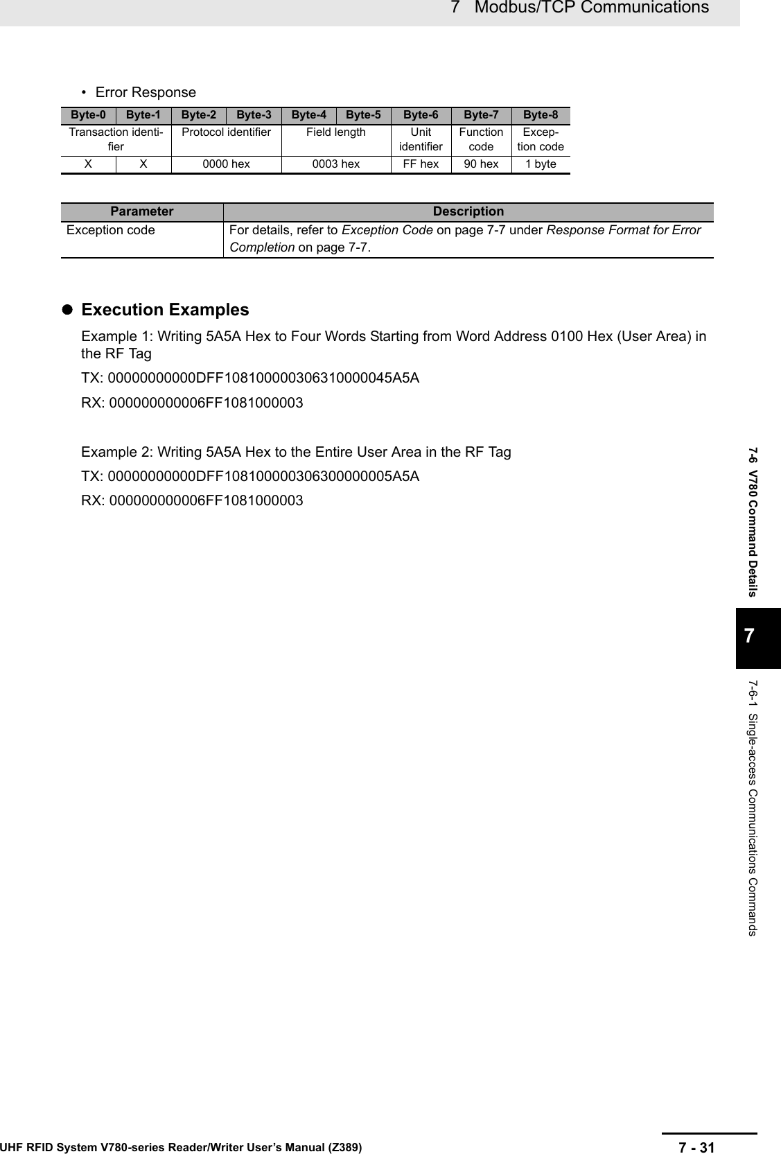
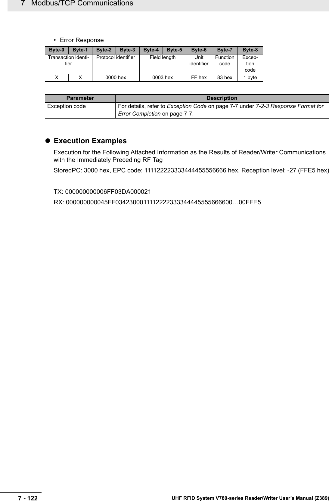
![7 - 1217 Modbus/TCP CommunicationsUHF RFID System V780-series Reader/Writer User’s Manual (Z389)7-6 V780 Command Details77-6-10 Maintenance Commands: RF Communications InformationFunctionThis command us used to check the attached information (i.e., the EPC code and reception level) that resulted from communications for a single-access command with the immediately preceding RF Tag .If communications for the immediately preceding single-access command ended in an error, attached information of 00 hex will be returned.Command FormatResponse Formats• Normal Response7-6-10 Maintenance Commands: RF Communications InformationGET RF TAG ADDITIONAL INFORMATIONByte-0 Byte-1 Byte-2 Byte-3 Byte-4 Byte-5 Byte-6 Byte-7 Byte-8 Byte-9 Byte-10 Byte-11Transaction identi-fierProtocol identifier Field length Unit identifierFunction codeRegister address Word countX X 0000 hex 0006 hex FF hex 03 hex DA00 hex 0021 hexParameter DescriptionRegister address The register address (DA00 hex) for reading the attached information for RF Tag communicationsWord count Always 0021 hex.Byte-0 Byte-1 Byte-2 Byte-3 Byte-4 Byte-5 Byte-6 Byte-7 Byte-8Transaction identi-fierProtocol identifier Field length Unit identifierFunction codeByte countX X 0000 hex 0045 hex FF hex 03 hex 42 hexByte-9 Byte-10 Byte-11 ... Byte-72 Byte-73 Byte-74StoredPC EPC code Reception level2 bytes 62 bytes 2 bytesParameter DescriptionStoredPC Gives the StoredPC data in 4-digit hexadecimal.The upper 5 bits are the EPC word length.EPC code Gives the Tag-specific information according to Gen2 standards.All bytes of the EPC code section that exceed the EPC word length in the StoredPC are filled with 00 hex.Reception level Gives the reception level in signed hexadecimal.FFFF to FF9D hex (-1 to -99) [dBm]](https://usermanual.wiki/Omron/V78068.Users-manual-2/User-Guide-3305498-Page-121.png)
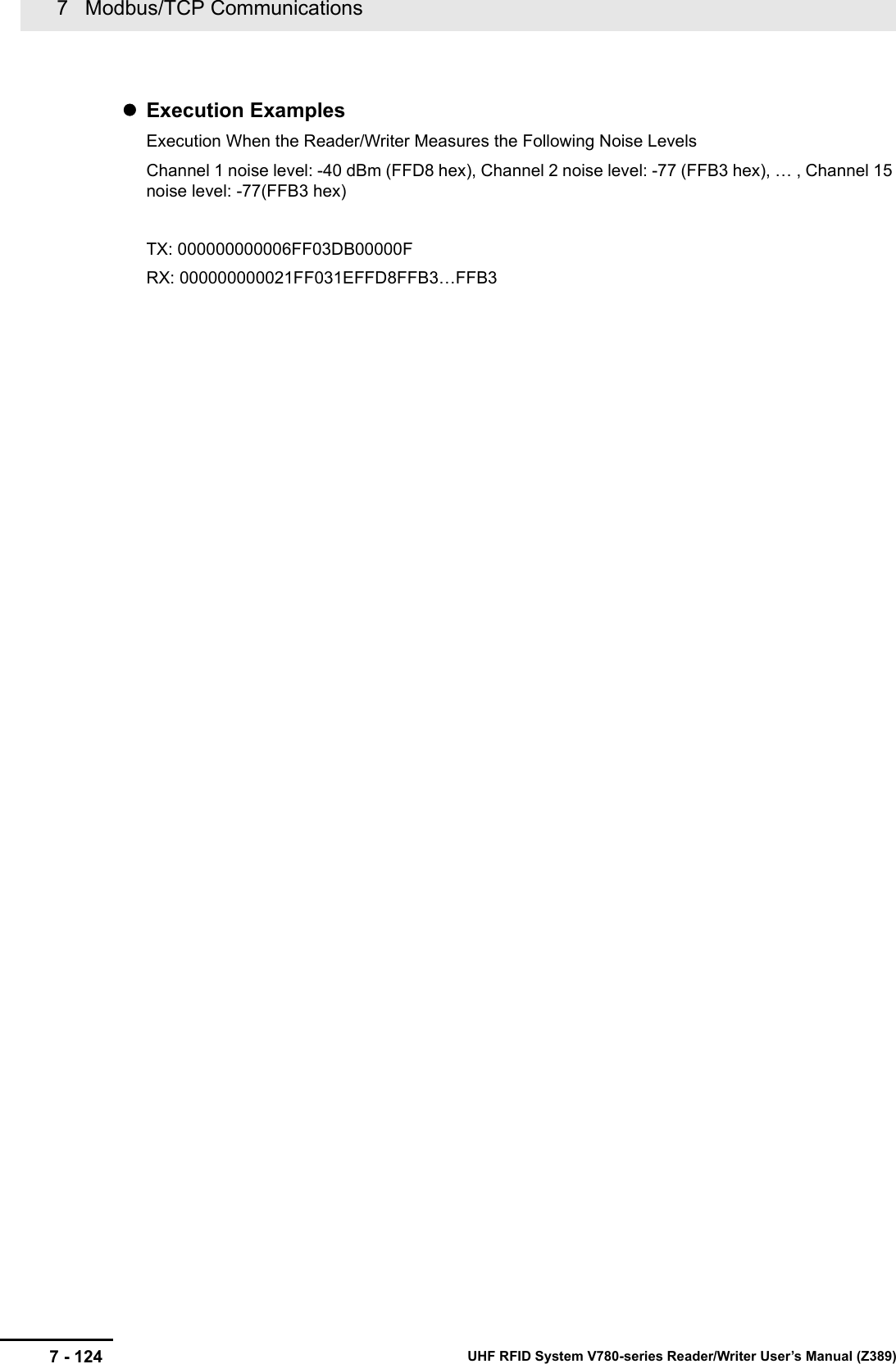
![7 - 1237 Modbus/TCP CommunicationsUHF RFID System V780-series Reader/Writer User’s Manual (Z389)7-6 V780 Command Details77-6-10 Maintenance Commands: RF Communications InformationFunctionThis command measures the ambient noise level around the Reader/Writer.Command FormatResponse Formats• Normal Response• Error ResponseGET NOISE LEVELByte-0 Byte-1 Byte-2 Byte-3 Byte-4 Byte-5 Byte-6 Byte-7 Byte-8 Byte-9 Byte-10 Byte-11Transaction identi-fierProtocol identifier Field length Unit identifierFunction codeRegister address Word countX X 0000 hex 0006 hex FF hex 03 hex DB00 hex 000F hexParameter DescriptionRegister address The register address (DB00 hex) for getting the noise levelWord count Always 000F hex.The noise information for channels 1 to 15 is read at the same time.Byte-0 Byte-1 Byte-2 Byte-3 Byte-4 Byte-5 Byte-6 Byte-7 Byte-8Transaction identi-fierProtocol identifier Field length Unit identifierFunction codeByte countX X 0000 hex 0021 hex FF hex 03 hex 1E hexByte-9 Byte-10 ... Byte-37 Byte-38Channel 1 noise level... Channel 15 noise level2 bytes ... 2 bytesParameter DescriptionChannel 1 noise level Gives the noise level for channel 1 in signed 2-digit hexadecimal.FFFF to FF9D hex (-1 to -99) [dBm]... ...Channel 15 noise level Gives the noise level for channel 15in signed 2-digit hexadecimal.FFFF to FF9D hex (-1 to -99) [dBm]Byte-0 Byte-1 Byte-2 Byte-3 Byte-4 Byte-5 Byte-6 Byte-7 Byte-8Transaction identi-fierProtocol identifier Field length Unit identifierFunction codeExcep-tion codeX X 0000 hex 0003 hex FF hex 83 hex 1 byteParameter DescriptionException code For details, refer to Exception Code on page 7-7 under 7-2-3 Response Format for Error Completion on page 7-7.](https://usermanual.wiki/Omron/V78068.Users-manual-2/User-Guide-3305498-Page-123.png)
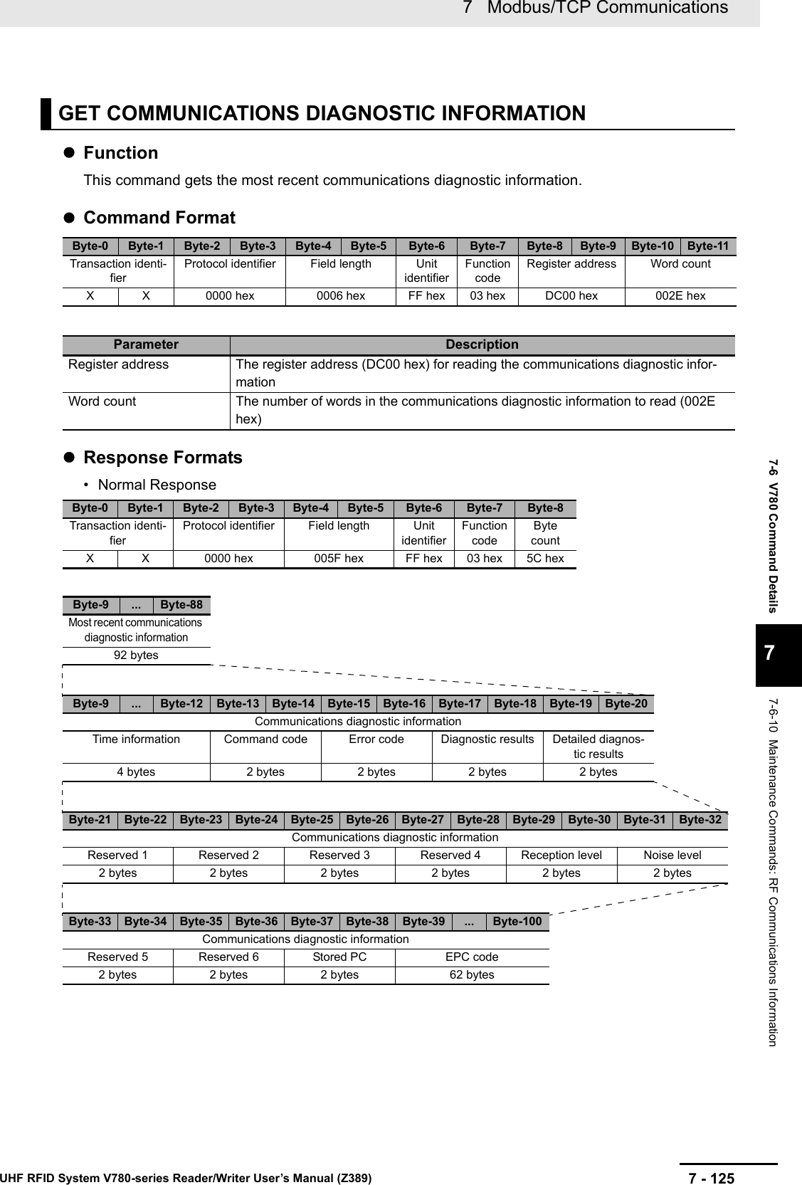
![7 Modbus/TCP Communications7 - 126 UHF RFID System V780-series Reader/Writer User’s Manual (Z389)*1. All of the most recent communications diagnostic information will be 00 hex if communications diagnostics are disabled.*2. This data is output for diagnostic processing only in Focus Mode. It is not output in any other mode.Parameter DescriptionByte count The number of bytes in the most recent communications diagnosis infor-mation (5C hex)Most recent com-munications diag-nostic informationTime informa-tionGives the time information in 8-digit hexadecimal(actual time flag, hour, minutes, and seconds).Command code Gives the command code in 8-digit hexadecimal.Error code For details, refer to Exception Code on page 7-7 under Response Format for Error Completion on page 7-7.Diagnostic resultsGives the diagnostic results in 4-digit hexadecimal.FFFF hex: Error (Set when the error code is not normal.)0000 hex: Normal0001 hex: Insufficient power to send0002 hex: Insufficient power to receive0003 hex: Too much noise0005 hex: Insufficient read data (Diagnostic processing for these results is performed only in Focus Mode.)0006 hex: Excessive read data (Diagnostic processing for these results is performed only in Focus Mode.)Diagnostic detailsGives the diagnostic details in 4-digit hexadecimal.Bit 0: Insufficient power to send flagBit 1: Insufficient power to receive flagBit 2: Too much noiseBit 3: ReservedBit 4: Insufficient data read flagBit 5: Excessive data read flagBits 6 to 15: Reserved (all zeros)*Bits 4 and 5 are output for diagnostic processing only in Focus Mode. They are not output in any other mode.Reserved 1 to 4 0000 hex: No specificationsReception level Gives the reception level in signed 4-digit hexadecimal.FFFF to FF9D hex (-1 to -99) [dBm]Noise level Gives the noise level in signed 4-digit hexadecimal.FFFF to FF9D hex (-1 to -99) [dBm]Reserved 5 and 60000 hex: No specificationsStored PC Gives the StoredPC data of the RF Tag for diagnostics in 4-digit hexadec-imal.The upper 5 bits are the EPC word length.EPC code Gives the Tag-specific information according to Gen2 standards.All bytes of the EPC code section that exceed the EPC word length in the StoredPC are filled with 00 hex.](https://usermanual.wiki/Omron/V78068.Users-manual-2/User-Guide-3305498-Page-126.png)