Contents
- 1. Users manual-1
- 2. Users manual-2
Users manual-2

7 - 1
7
UHF RFID System V780-series Reader/Writer User’s Manual (Z389)
This section provides an overview of Modbus/TCP communications and describes the
communications format, communications commands, and communications procedure.
7-1 Outline . . . . . . . . . . . . . . . . . . . . . . . . . . . . . . . . . . . . . . . . . . . . . . . . . . . . . . . 7-2
7-1-1 Modbus/TCP Communications . . . . . . . . . . . . . . . . . . . . . . . . . . . . . . . . . . . . 7-2
7-1-2 Modbus/TCP Function Codes Supported by the V780 . . . . . . . . . . . . . . . . . . 7-2
7-1-3 Communications System . . . . . . . . . . . . . . . . . . . . . . . . . . . . . . . . . . . . . . . . 7-3
7-2 Message Formats . . . . . . . . . . . . . . . . . . . . . . . . . . . . . . . . . . . . . . . . . . . . . . 7-5
7-2-1 Command Format . . . . . . . . . . . . . . . . . . . . . . . . . . . . . . . . . . . . . . . . . . . . . . 7-5
7-2-2 Response Format for Normal Completion . . . . . . . . . . . . . . . . . . . . . . . . . . . 7-6
7-2-3 Response Format for Error Completion . . . . . . . . . . . . . . . . . . . . . . . . . . . . . 7-7
7-2-4 Read Multiple Resisters Command/Response (FC03) . . . . . . . . . . . . . . . . . . 7-8
7-2-5 Write Multiple Resisters Command/Response (FC16) . . . . . . . . . . . . . . . . . . 7-8
7-2-6 Expanded Command/Response (FC100) . . . . . . . . . . . . . . . . . . . . . . . . . . . 7-8
7-3 RF Communications Command Options . . . . . . . . . . . . . . . . . . . . . . . . . . . 7-9
7-4 Communications Procedure . . . . . . . . . . . . . . . . . . . . . . . . . . . . . . . . . . . . 7-11
7-4-1 Command Communications Procedure . . . . . . . . . . . . . . . . . . . . . . . . . . . . .7-11
7-4-2 Error Response Reception Procedure . . . . . . . . . . . . . . . . . . . . . . . . . . . . . 7-12
7-4-3 RF Tag Communications Command Procedure for Single-access
Communications . . . . . . . . . . . . . . . . . . . . . . . . . . . . . . . . . . . . . . . . . . . . . . 7-13
7-4-4 RF Tag Communications Command Procedure for Multiaccess
Communications . . . . . . . . . . . . . . . . . . . . . . . . . . . . . . . . . . . . . . . . . . . . . . 7-14
7-5 Commands . . . . . . . . . . . . . . . . . . . . . . . . . . . . . . . . . . . . . . . . . . . . . . . . . . 7-17
7-6 V780 Command Details . . . . . . . . . . . . . . . . . . . . . . . . . . . . . . . . . . . . . . . . 7-20
7-6-1 Single-access Communications Commands . . . . . . . . . . . . . . . . . . . . . . . . 7-20
7-6-2 Multiaccess Communications Commands . . . . . . . . . . . . . . . . . . . . . . . . . . 7-32
7-6-3 Modbus Expansion Communications Commands . . . . . . . . . . . . . . . . . . . . 7-41
7-6-4 Reader/Writer Control Commands . . . . . . . . . . . . . . . . . . . . . . . . . . . . . . . . 7-49
7-6-5 Reader/Writer Setting Commands: Network Settings . . . . . . . . . . . . . . . . . . 7-54
7-6-6 Reader/Writer Setting Commands: Communications Settings . . . . . . . . . . . 7-70
7-6-7 Reader/Writer Setting Commands: Device Settings . . . . . . . . . . . . . . . . . . . 7-98
7-6-8 Maintenance Commands: Device Information . . . . . . . . . . . . . . . . . . . . . . 7-102
7-6-9 Maintenance Commands: Log Information . . . . . . . . . . . . . . . . . . . . . . . . . .7-113
7-6-10 Maintenance Commands: RF Communications Information . . . . . . . . . . . 7-121
Modbus/TCP Communications
7 Modbus/TCP Communications
7 - 2 UHF RFID System V780-series Reader/Writer User’s Manual (Z389)
7-1 Outline
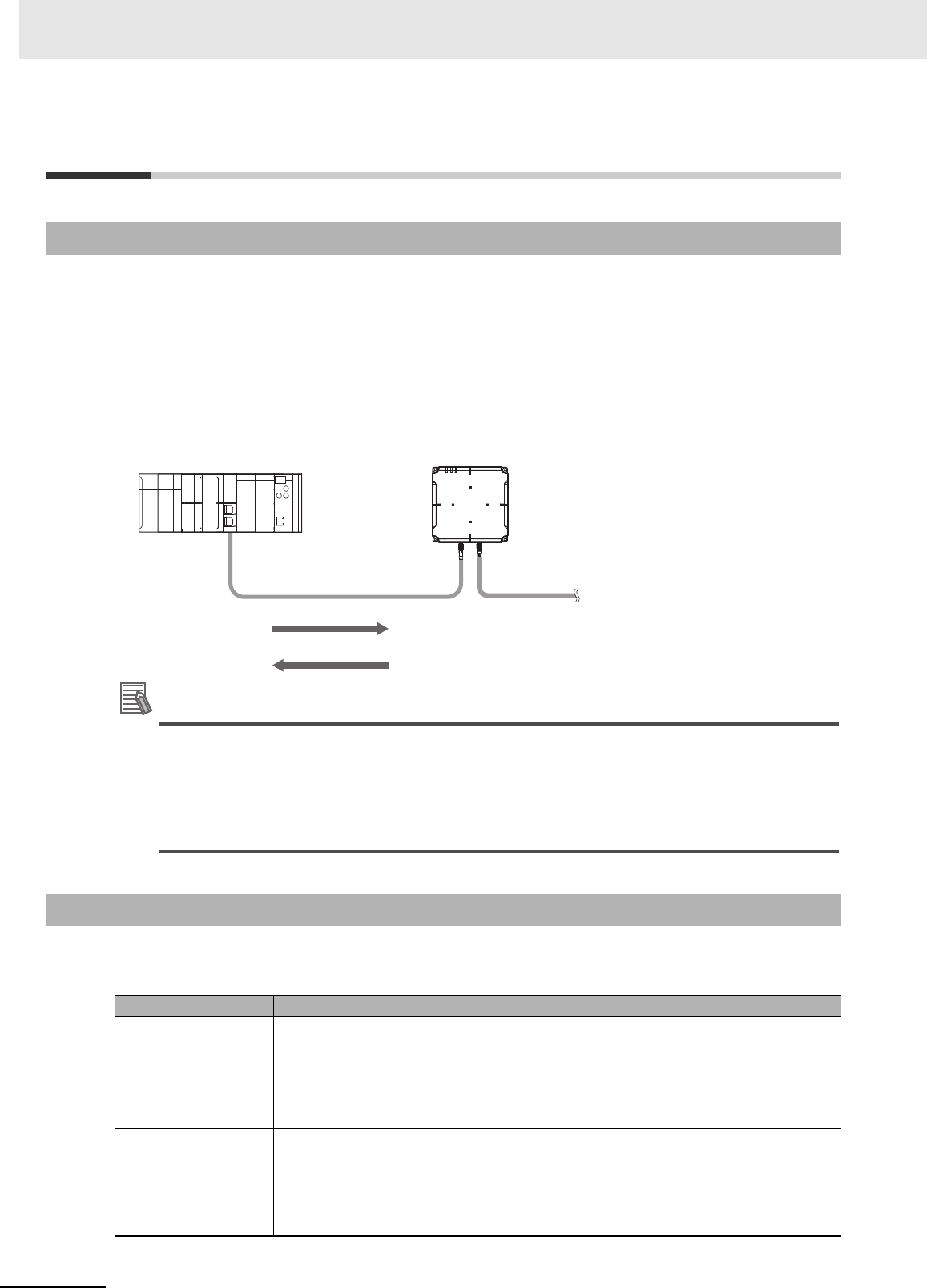
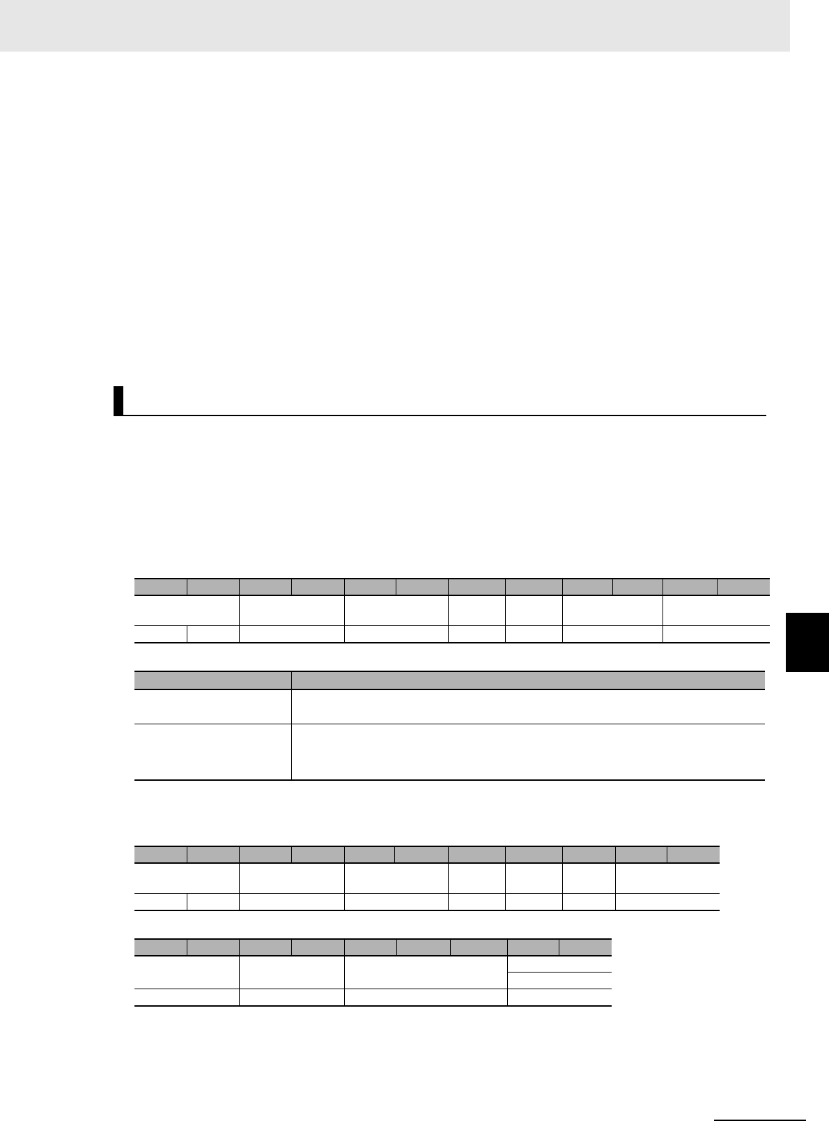
• A V780 Reader/Writer can perform Modbus/TCP-compliant message communications with the host
device (PLC).
• Communications between the host device (PLC) and the V780 Reader/Writer are performed on a cli-
ent-server basis using the TCP/IP protocol. The computer, PLC, or other host device is the client and
the Reader/Writer is the server.
• The message that the host device (PLC) sends to the Reader/Writer is called a command. The mes-
sage that the Reader/Writer returns is called the response.
Additional Information
Modbus/TCP Protocol
The Modbus/TCP protocol is a communications protocol developed for PLCs by Modicon
Inc.(AEG Schneider Automation International S.A.S.). It is an open standard and has been
used for a variety of industrial devices.
A query in Modbus/TCP communications is called a command in this manual.
The Modbus/TCP function codes that are supported by the V780 Reader/Writer are given in the follow-
ing table.
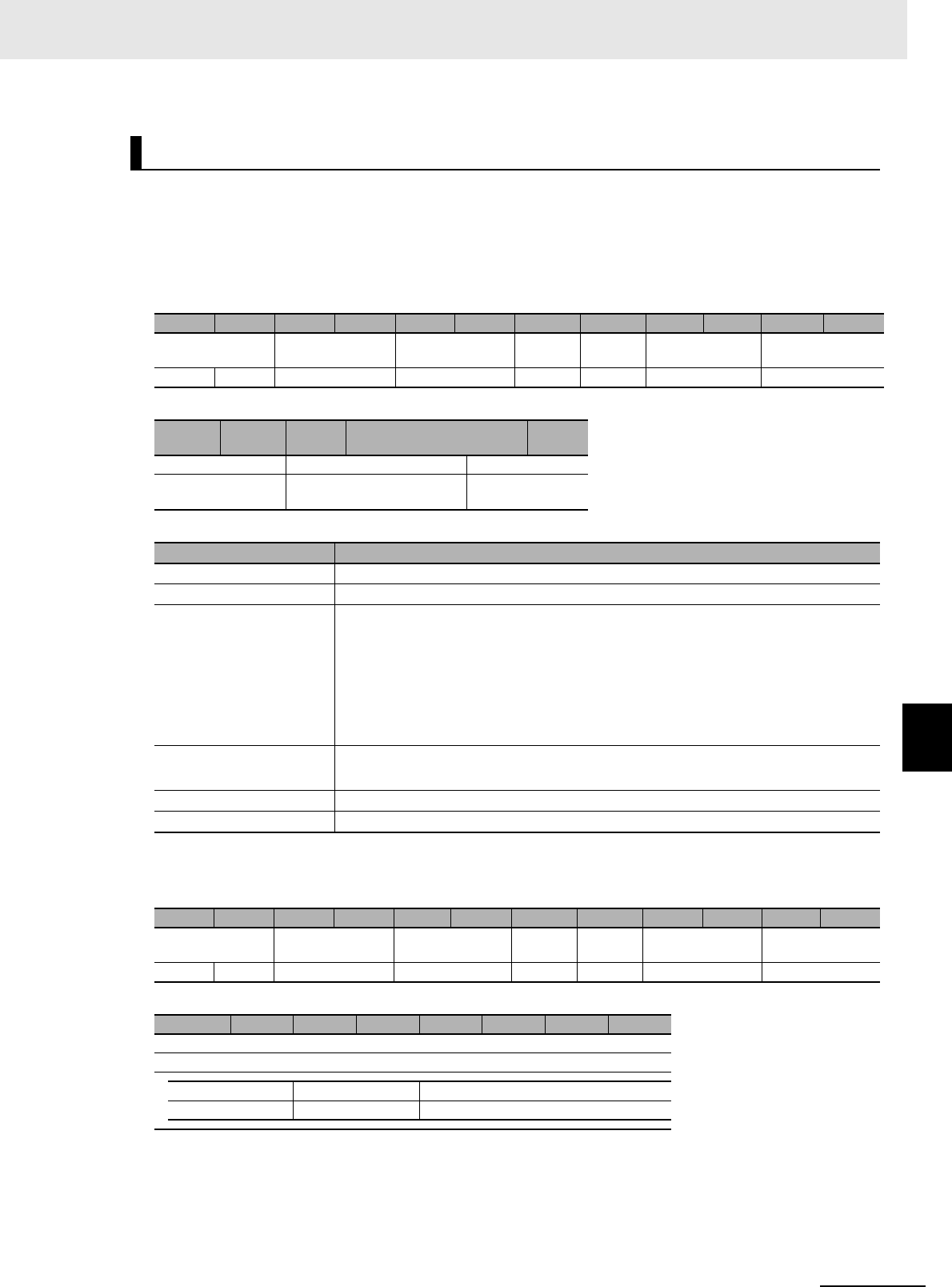
7-1-1 Modbus/TCP Communications
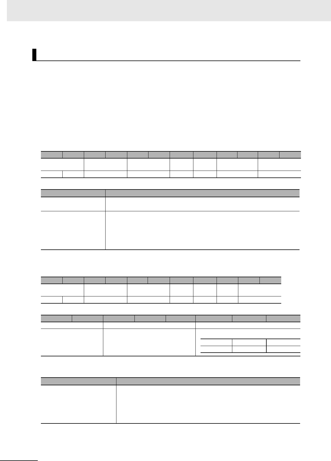
7-1-2 Modbus/TCP Function Codes Supported by the V780
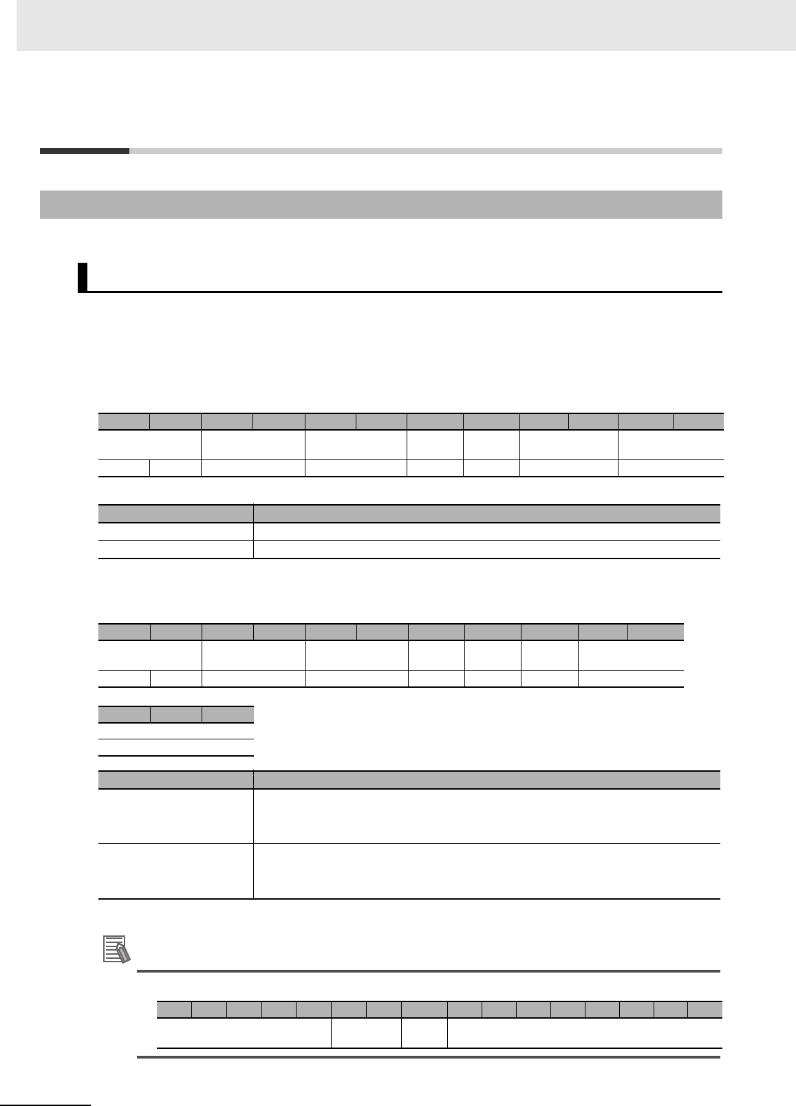
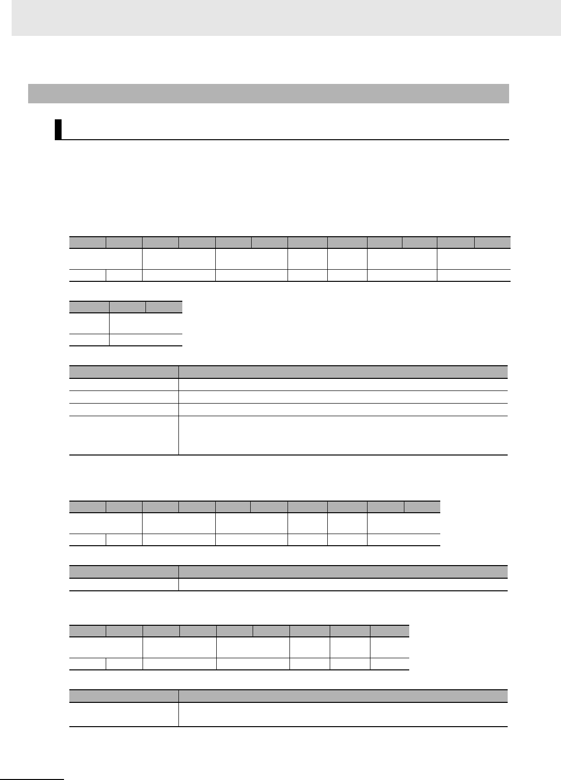
Function code Description
FC03 and FC16
(normal commands)
These function codes comply with Modbus/TCP Class 0.
The basic Modbus/TCP function codes are classified in Class 0.
Class 0 contains the following two functions: Read Multiple Resisters (FC03) and Write
Multiple Registers (FC16).
These are called normal commands in this manual.
FC100
(expanded command)
This function code has a unique format that was defined by OMRON.
This function code is used to reduce command/response exchanges between the host
device and Reader/Writer and give priority to the performance of communications with
the host device.
This is called an expanded command in this manual.
Host device
(client)
Reader/Writer
(server)
Ethernet Cable
TCP port number: 502
Command
Response
Power Supply Cable
7 - 3
7 Modbus/TCP Communications
UHF RFID System V780-series Reader/Writer User’s Manual (Z389)
7-1 Outline
7
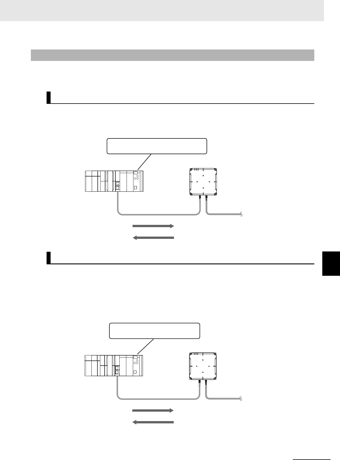
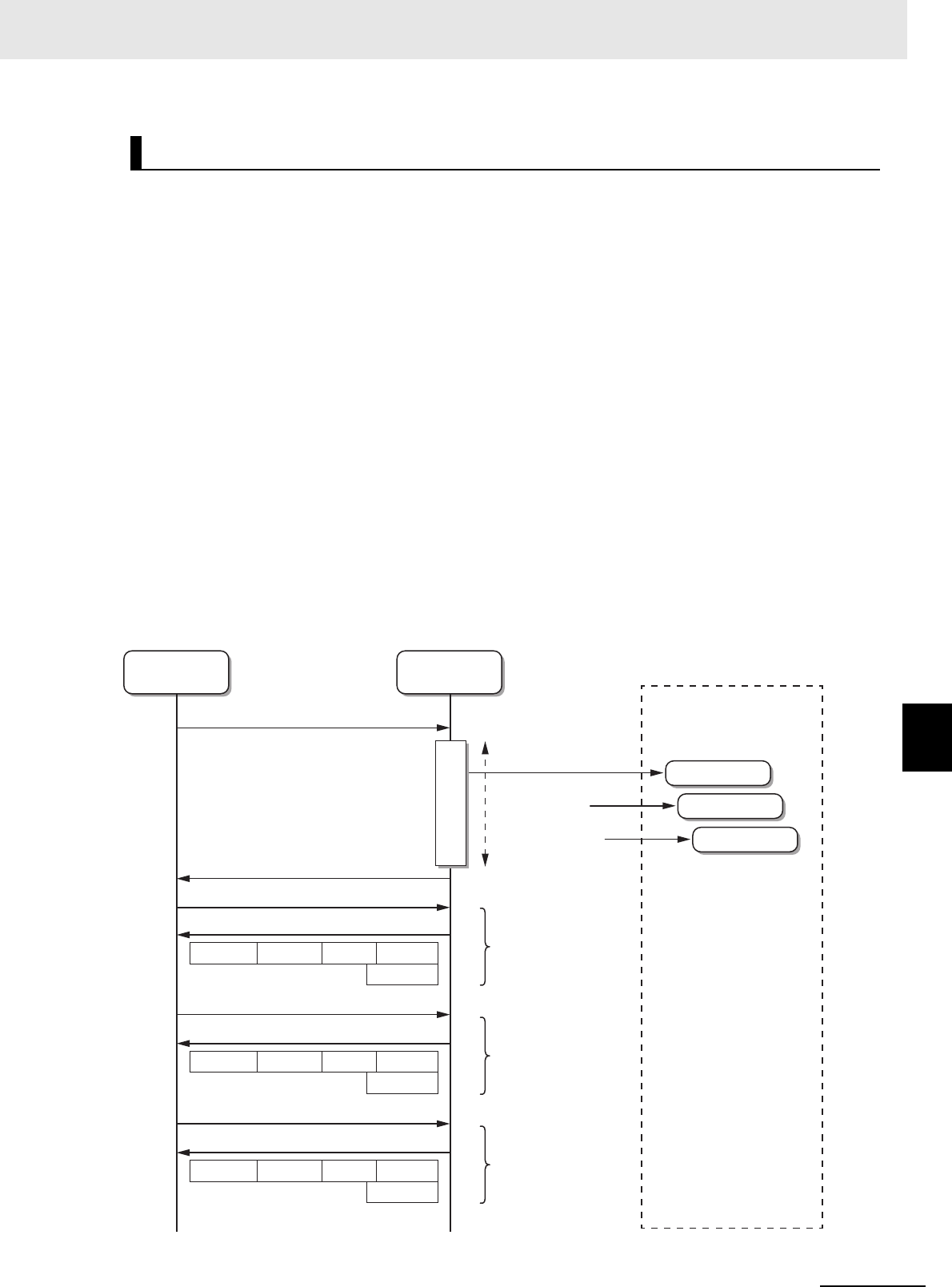
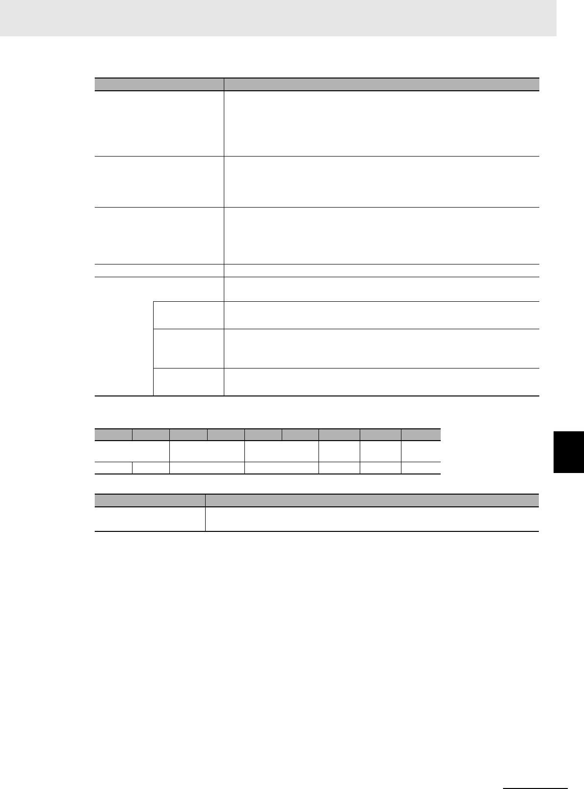
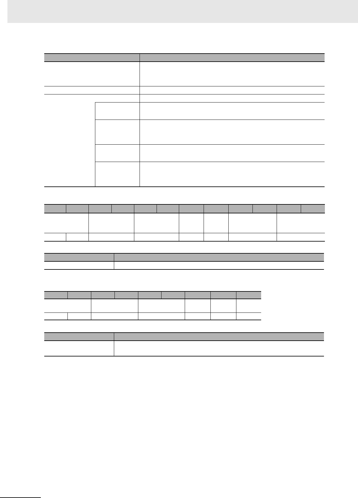
7-1-3 Communications System
There are two communications systems used by the V780 depending on the function codes that are
used.
The communications system that uses normal commands that are compliant with Modbus/TCP Class 0
is shown below.
Refer to 7-2 Message Formats on page 7-5 for details on the normal commands.
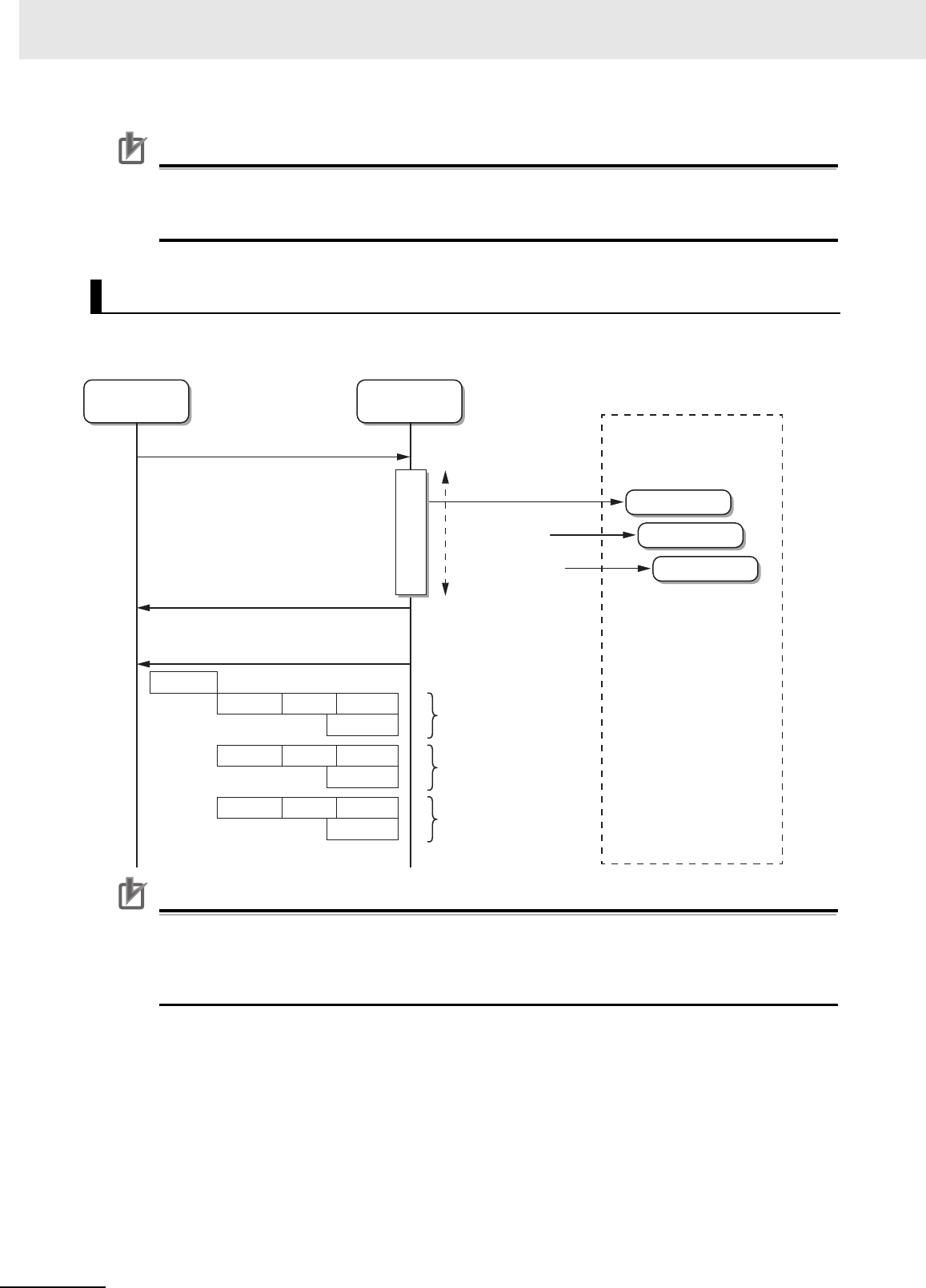
The expanded command that has a unique format defined by OMRON (FC100) cannot be sent with a
Modbus/TCP Class 0-compliant protocol. The TCP/IP socket communications of the host device (PLC)
are used instead.
Refer to 7-2 Message Formats on page 7-5 for details on the expanded communications commands.
Refer to 7-4 Communications Procedure on page 7-11 for information on creating a program for TCP/IP
communications.
7-1-3 Communications System
Modbus/TCP Communications System (FC03 and FC16)
TCP/IP Socket Communications System (FC03, FC16, and FC100)
Host device
(client)
Reader/Writer
(server)
Ethernet Cable
FC03 or FC16
TCP port number: 502
Command
Response
Power Supply Cable
Modbus/TCP communications instructions
Modbus/TCP Unit or other applicable Unit
Host device
(client)
Reader/Writer
(server)
Ethernet Cable
FC03, FC16, or FC100
TCP port number: 502
Command
Response
Power Supply Cable
Socket communications instructions
Ethernet Unit or other applicable Unit

7 Modbus/TCP Communications
7 - 4 UHF RFID System V780-series Reader/Writer User’s Manual (Z389)
Precautions for Correct Use
Communications Units and communications commands that support the Modbus/TCP protocol
support only function codes that comply with Modbus/TCP Class 0. Therefore, the function
code FC100 for expanded commands cannot be used.
You can set any IP address for the V780 Reader/Writer.
For details, refer to 7-6-5 Reader/Writer Setting Commands: Network Settings on page 7-54 or Setting
the IP Address of the Reader/Writer from a Web Browser on page 5-4.
Normally, port number 502 (01F6 hex) is used for Modbus/TCP communications.
With the V780 Reader/Writer, you can change the port number to between 1,024 and 65,535 (0400 hex
and FFFF hex).
For details, refer to ?8-2-3 ???????? (P.8-5)?.
IP Address Settings of the Reader/Writer
Port Numbers Used for Modbus/TCP Communications
7 - 5
7 Modbus/TCP Communications
UHF RFID System V780-series Reader/Writer User’s Manual (Z389)
7-2 Message Formats
7
7-2-1 Command Format
7-2 Message Formats
This value is used to identify the message sent by the host device.
The transaction identifier in the response from the Reader/Writer will be a copy of the value that is
specified here.
This field is always 0000 hex.
Specify the number of bytes inclusively from the unit identifier through the end of the data.
If the function code is FC03 or FC16, the maximum field length is 250 bytes.
If the function code is FC100, the maximum field length is 4,346 bytes.
This field is always FF hex.
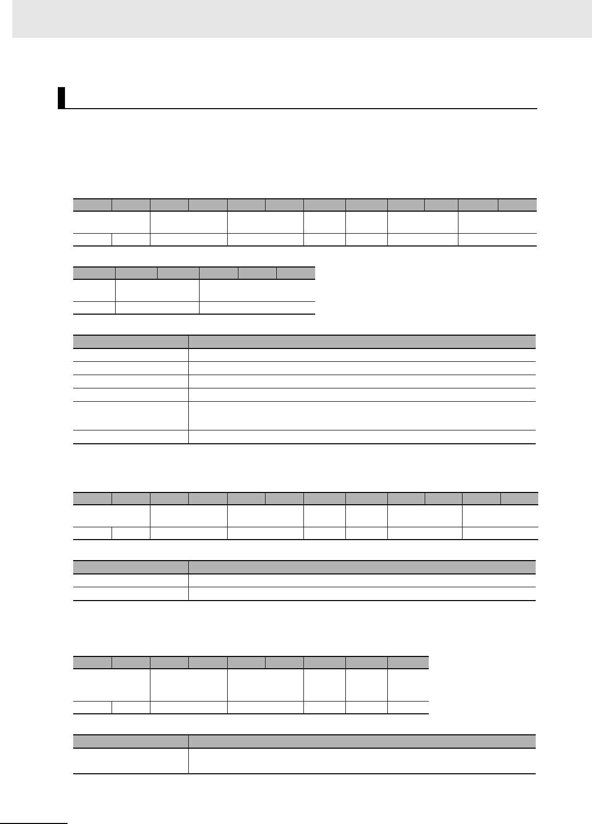
The function code indicates the command to request execution from the Reader/Writer.
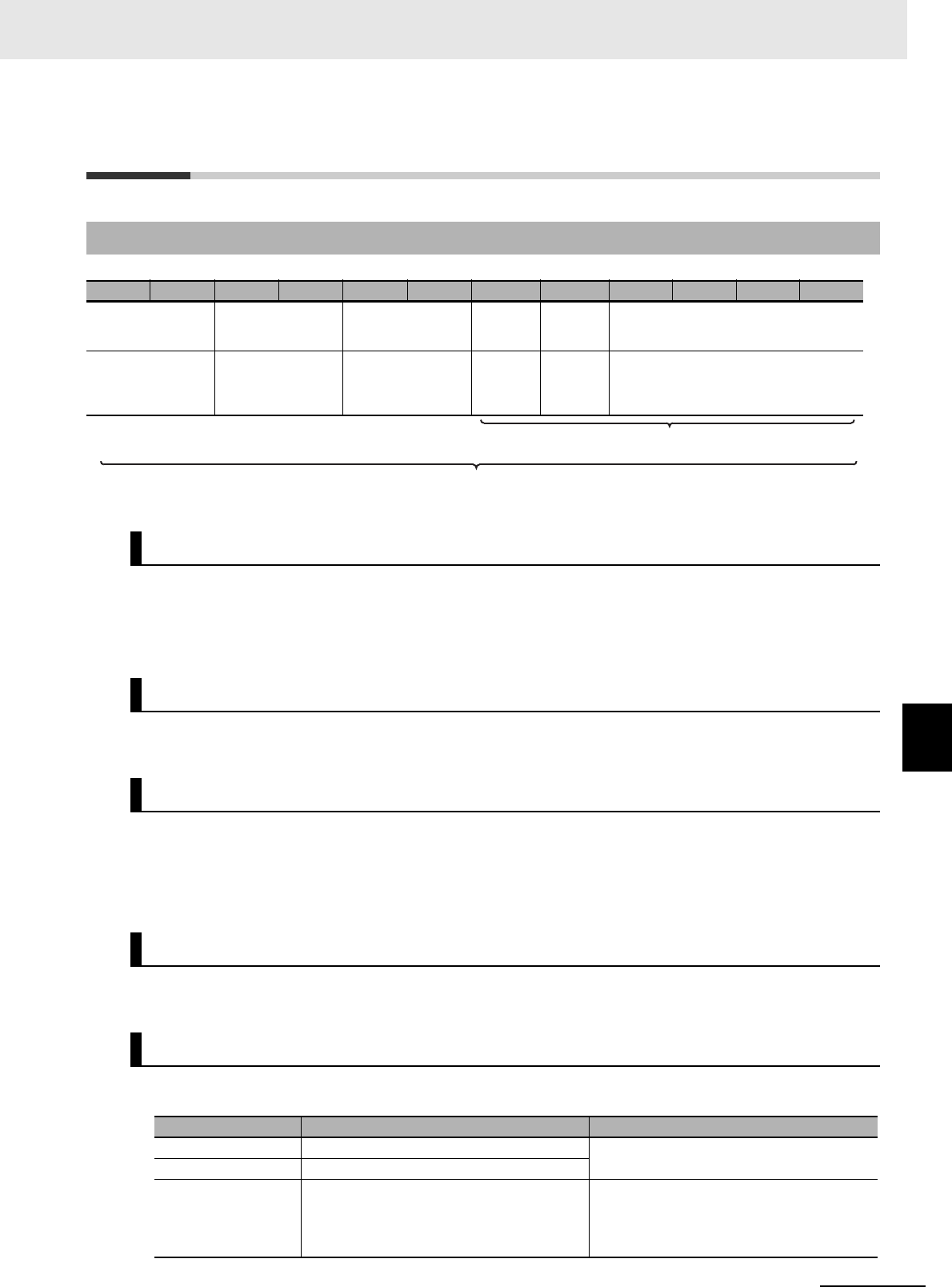
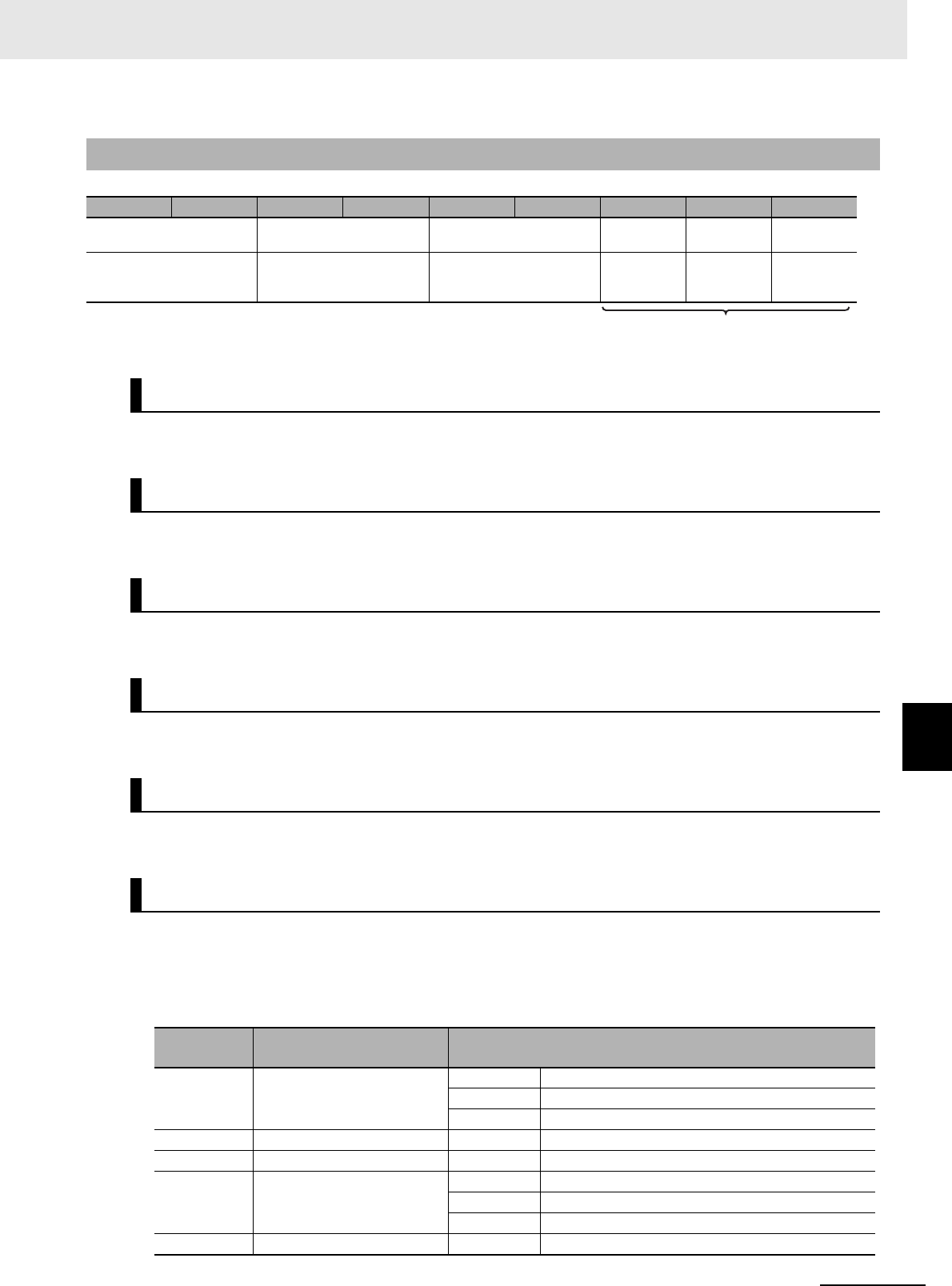
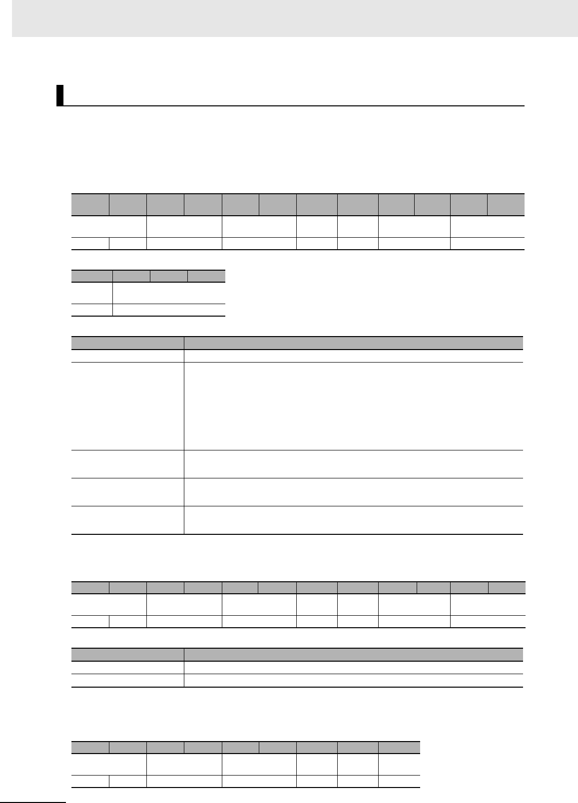
7-2-1 Command Format
Byte-0 Byte-1 Byte-2 Byte-3 Byte-4 Byte-5 Byte-6 Byte-7 Byte-8 Byte-9 … Byte-n
Transaction iden-
tifier Protocol identifier Field length Unit
identifier
Func-
tion
code
Data
XXXX hex Always 0000 hex. XXXX hex Always
FF hex.
03 hex,
10 hex,
or 64
hex
XX...XX hex
X: Any value, n: 4,351 max.
Transaction Identifier
Protocol Identifier
Field Length
Unit Identifier
Function Code
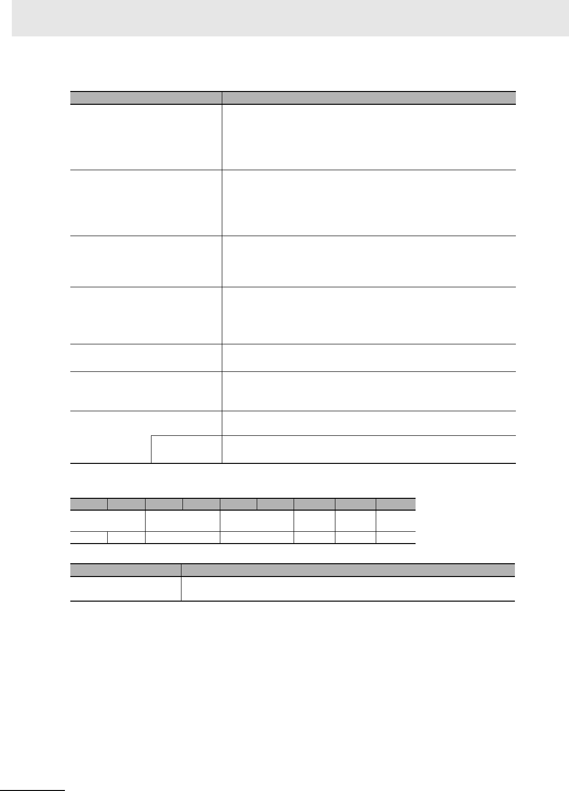
Function code Function Remarks
FC03 (03 hex) Read Holding Register Modbus/TCP Class 0 compliant
FC16 (10 hex) Write Holding Register
FC100 (64 hex) Reader/Writer command
This function code is used for commands
with a unique manufacturer definition that
gives priority to the performance of commu-
nications with the host device.
Range included in the field length.
Command frame length
7 Modbus/TCP Communications
7 - 6 UHF RFID System V780-series Reader/Writer User’s Manual (Z389)
Specify the data that is relevant to the function code.
The format of the data depends on the function code.
The value that was specified in the command is set.
This field is always 0000 hex.
The number of bytes inclusively from the unit identifier through the end of the data is set.
This field is always FF hex.
The value of the function code that was specified in the command is set.
The data that is relevant to the function code is set.
The format of the data depends on the function code.
Data
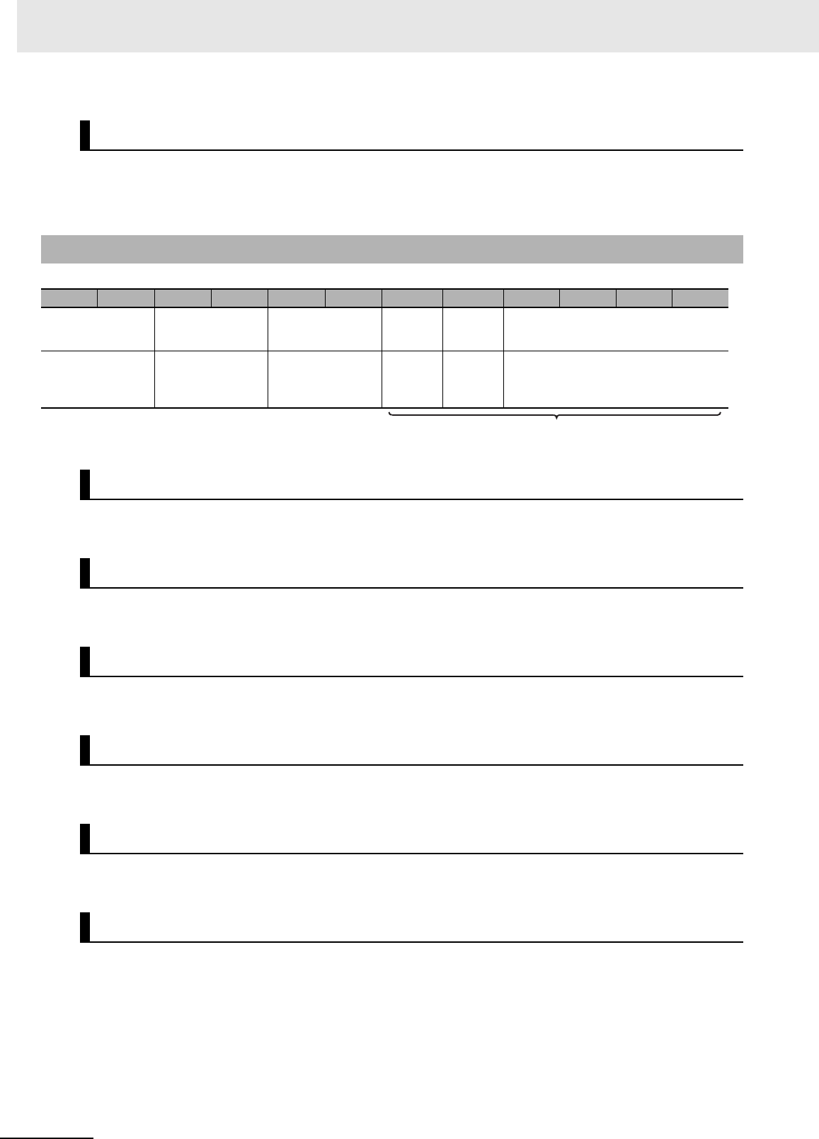
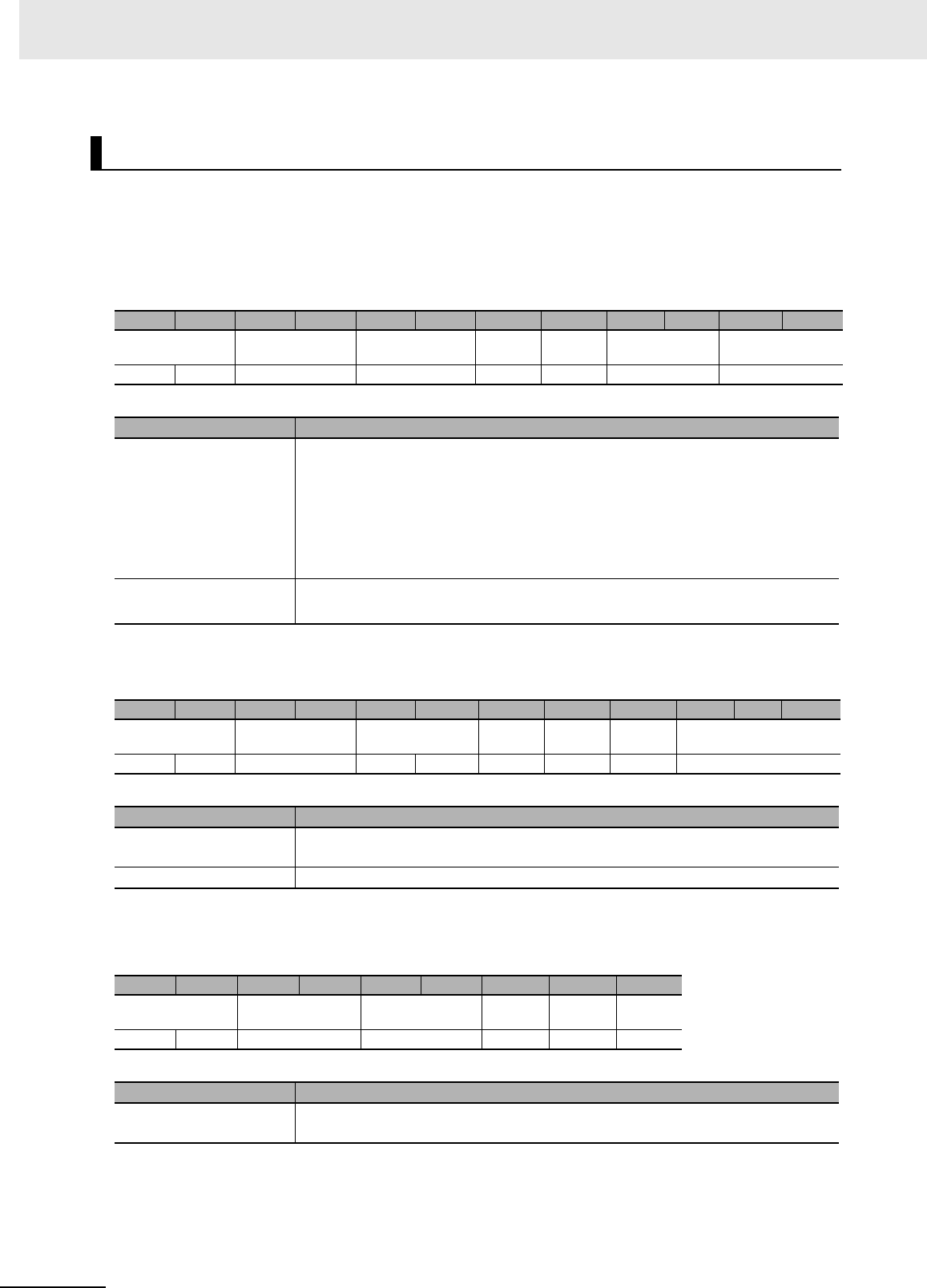
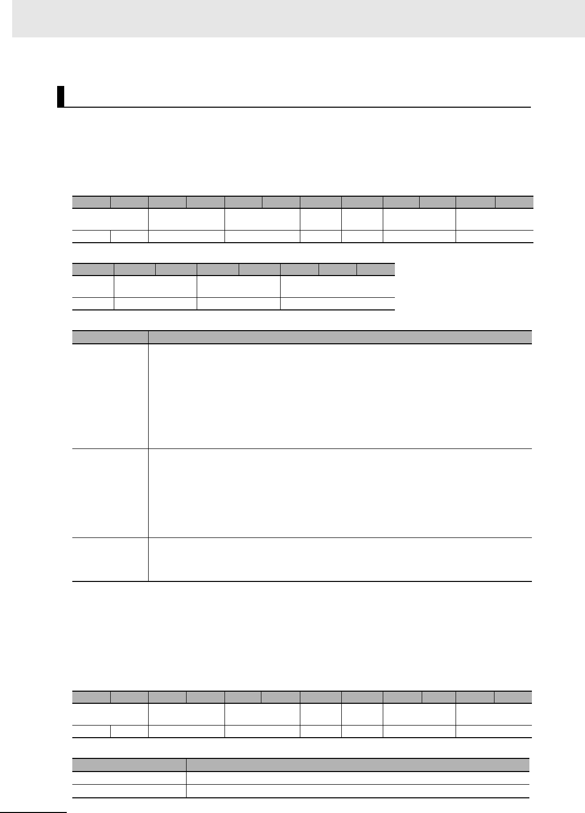
7-2-2 Response Format for Normal Completion
Byte-0 Byte-1 Byte-2 Byte-3 Byte-4 Byte-5 Byte-6 Byte-7 Byte-8 Byte-9 …Byte-n
Transaction iden-
tifier Protocol identifier Field length Unit
identifier
Func-
tion
code
Data
XXXX hex Always 0000 hex. XXXX hex Always
FF hex.
03 hex,
10 hex,
or 64
hex
XX...XX hex
X: Any value, n: 9,215 max.
Transaction Identifier
Protocol Identifier
Field Length
Unit Identifier
Function Code
Data
Range included in the field length.
7 - 7
7 Modbus/TCP Communications
UHF RFID System V780-series Reader/Writer User’s Manual (Z389)
7-2 Message Formats
7
7-2-3 Response Format for Error Completion
The value that was specified in the command is set.
This field is always 0000 hex.
This field is always 0003 hex.
This field is always FF hex.
The value of the function code that was specified in the command plus 80 hex is set.
A code that provides information on the error is set.
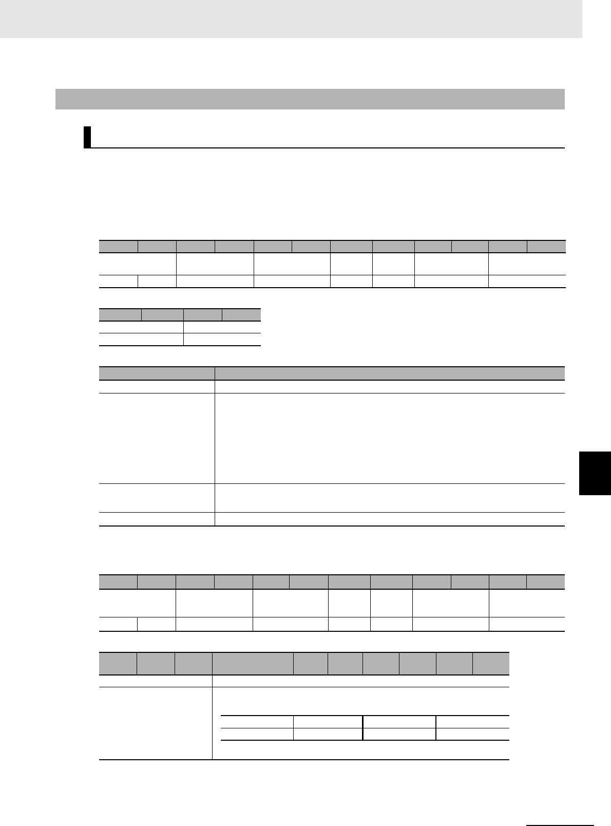
You can use the error code to identify the error that was detected by the Reader/Writer. The exception
code and error code are related as given below. Refer to the most recent command error information or
command error log to check details on the error using the error code.
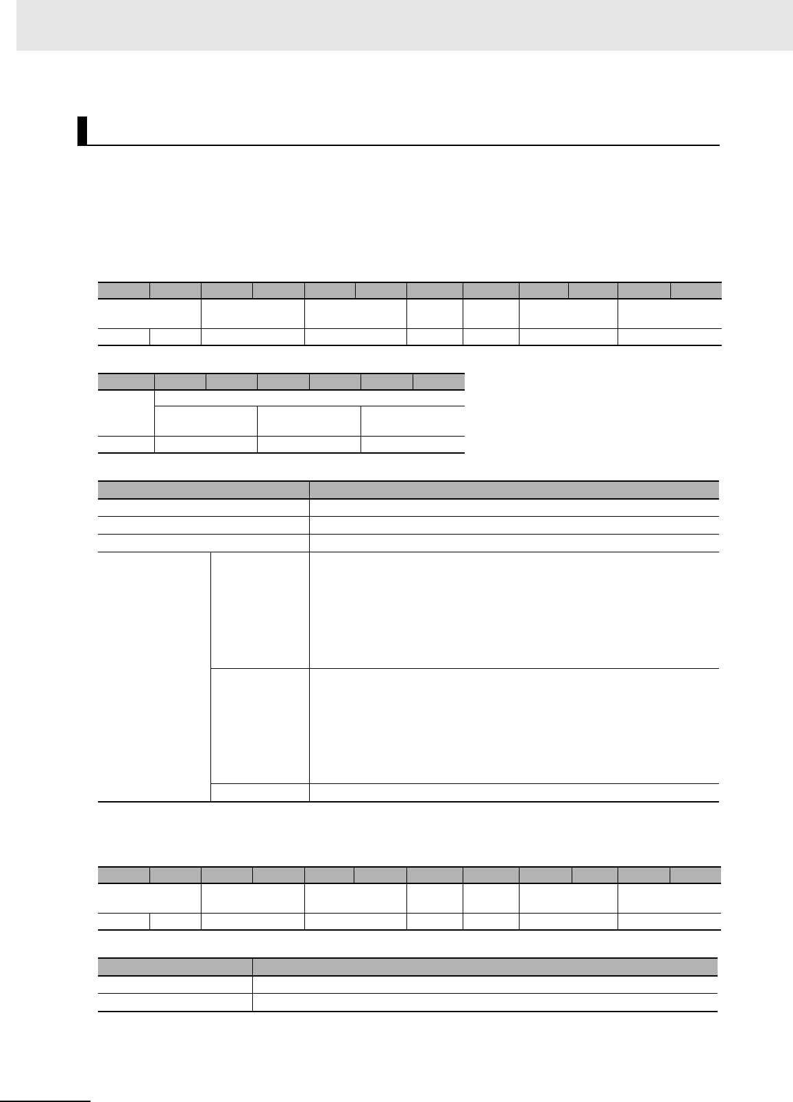
7-2-3 Response Format for Error Completion
Byte-0 Byte-1 Byte-2 Byte-3 Byte-4 Byte-5 Byte-6 Byte-7 Byte-8
Transaction identifier Protocol identifier Field length Unit identi-
fier
Function
code
Exception
code
XXXX hex Always 0000 hex. Always 0003 hex. Always FF
hex.
83 hex, 90
hex, or E4
hex
XX hex
X: Any value
Transaction Identifier
Protocol Identifier
Field Length
Unit Identifier
Function Code
Exception Code
Exception
code Exception code meaning V780 error code
01 hex Illegal function
1001 hex Frame length error
1002 hex Frame header error
1003 hex Unknown command error
02 hex Illegal data address 1004 hex Command format error
03 hex Illegal data value 1005 hex Command parameter error
04 hex Failure in slave device
2*** hex RF Tag communications error
1018 hex Command execution failure, minor fault
101F hex Command execution failure, major fault
06 hex Slave device busy 1011 hex Command execution failure, busy
Range included in the field length.
7 Modbus/TCP Communications
7 - 8 UHF RFID System V780-series Reader/Writer User’s Manual (Z389)
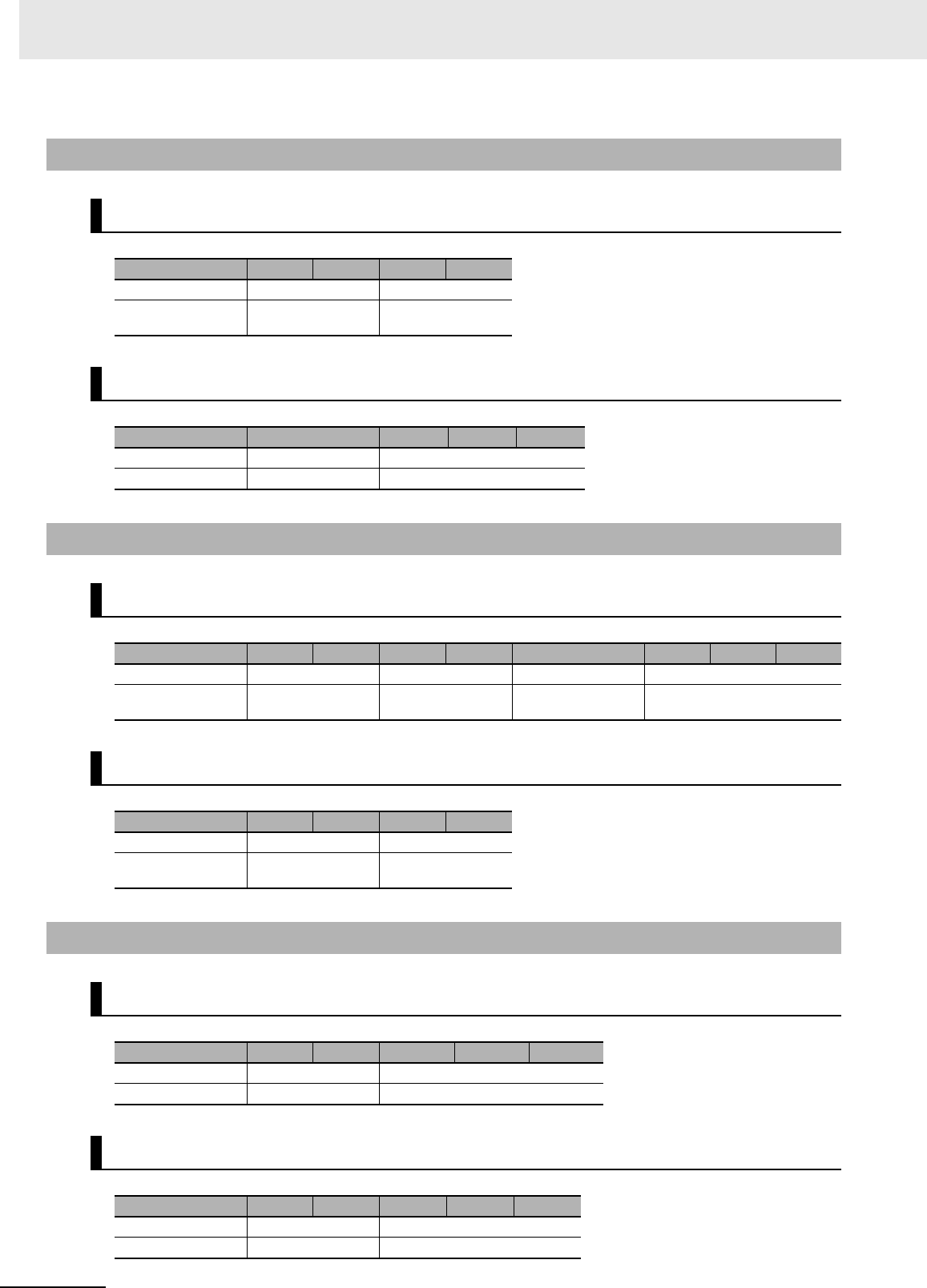
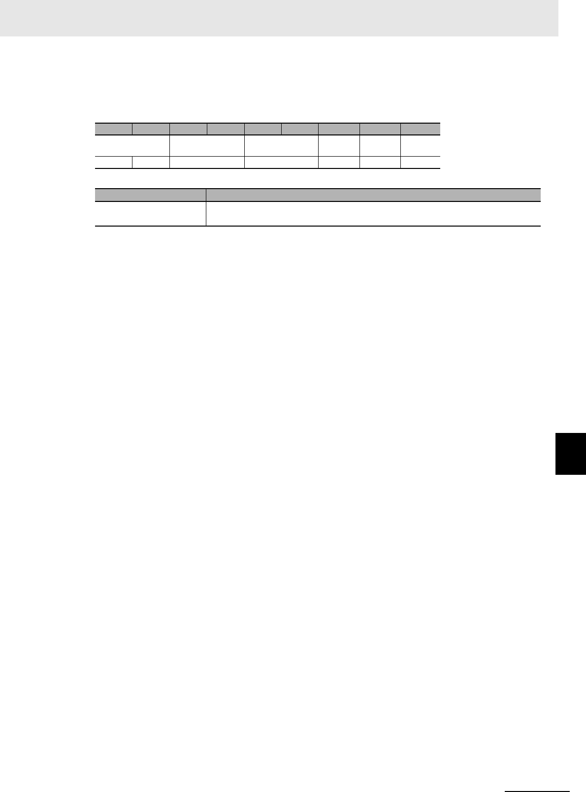
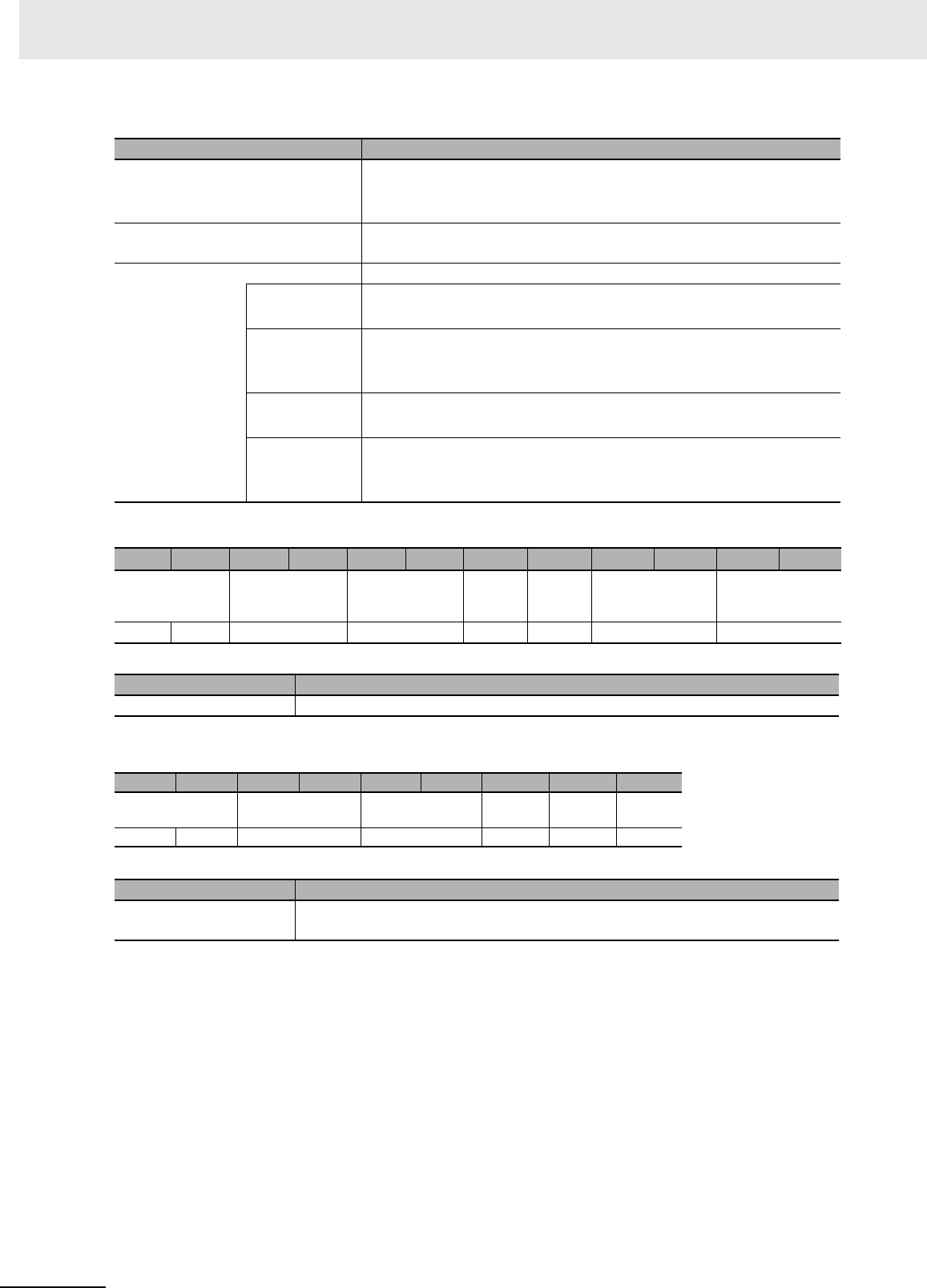
7-2-4 Read Multiple Resisters Command/Response (FC03)
Command Format
Byte-7 Byte-8 Byte-9 Byte-10 Byte-11
Function code Register address Word count
03 hex XXXX hex 0001 to 0078 hex
(1 to 120)
Normal Response Format
Byte-7 Byte-8 Byte-9 … Byte-n
Function code Byte count Read holding register data
03 hex XX hex XX...XX hex
7-2-5 Write Multiple Resisters Command/Response (FC16)
Command Format
Byte-7 Byte-8 Byte-9 Byte-10 Byte-11 Byte-12 Byte-13 …Byte-n
Function code Register address Word count Byte count Write holding register data
10 hex XXXX hex 0001 to 0078 hex
(1 to 120) Word count x 2 XX...XX hex
Normal Response Format
Byte-7 Byte-8 Byte-9 Byte-10 Byte-11
Function code Register address Word count
10 hex XXXX hex 0001 to 0078 hex
(1 to 120)
7-2-6 Expanded Command/Response (FC100)
Command Format
Byte-7 Byte-8 Byte-9 Byte-10 … Byte-n
Function code Subfunction code Expanded command parameters
64 hex XXXX hex XX...XX hex
Normal Response Format
Byte-7 Byte-8 Byte-9 Byte-10 … Byte-n
Function code Subfunction code Expanded response data
64 hex XXXX hex XX...XX hex
7 - 9
7 Modbus/TCP Communications
UHF RFID System V780-series Reader/Writer User’s Manual (Z389)
7-3 RF Communications Command Options
7
7-3 RF Communications Command
Options
This section describes the options that you can use together with RF communications commands (mul-
tiaccess or Modbus expansion). You can specify options to get the EPC of the RF Tag, the reception
level, or other communications information together with the normal data for the command.
For commands with the multiaccess specification, the communications information specified with the
option is returned in the response for the command that gets the execution results, i.e., the two com-
mands are used together.
For commands with the Modbus expansion, the communications information specified with the option is
returned as an attachment to the response.
Options
Option Specification Examples:
Specify 0001 hex to have the EPC attached.
Specify 0003 hex to have the EPC and reception level attached.
Specify 0011 hex to have the EPC and diagnostic results attached.
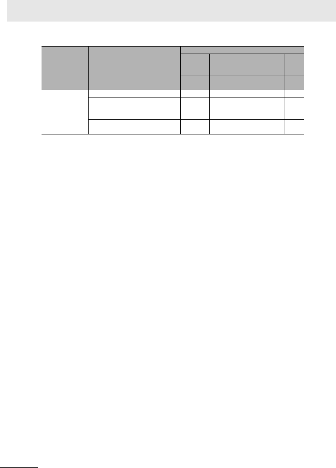
Options Supported by RF Communications Commands
OK: Option can be specified, No: Option cannot be specified. (A parameter error will occur if it is.)
---: Reserved (Always specify 0 for these unused bits.)
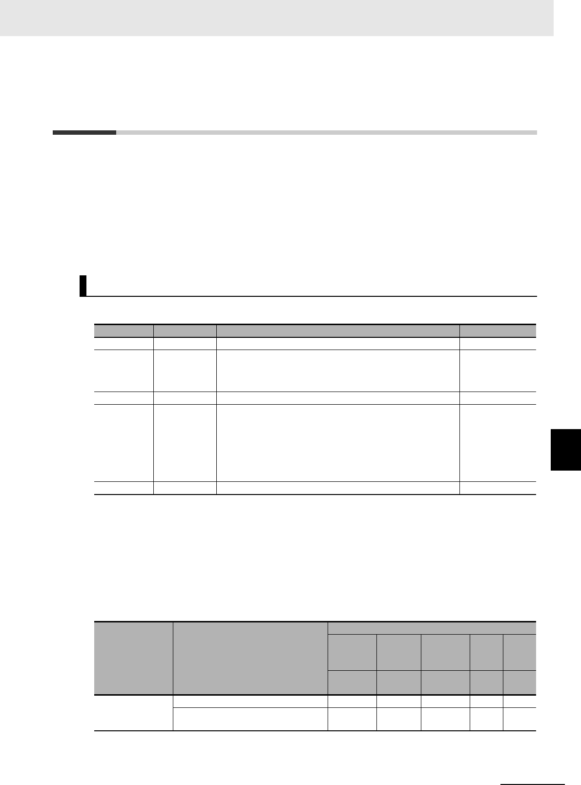
Options
Item Relevant bit Description Information size
EPC Bit 0 The StoredPC and EPC code are attached. 32 words
Reception
level
Bit 1 The reception level (signed hexadecimal) is attached.
FFFF to FF9D hex (-1 to -99 [dBm])
• A value of 0 will be set if processing ended in an error.
1 word
Reserved 1 Bits 2 to 3 • These bits are reserved. ---
Diagnostic
result
Bit 4 The diagnostic results (4-digit hexadecimal) are attached.
If communications diagnostics are disabled, 0000 hex is
attached.
For details, refer to Response Formats on page 7-125 under
GET COMMUNICATIONS DIAGNOSTIC INFORMATION on
page 7-125.
1 word
Reserved 2 Bits 5 to 15 • These bits are reserved. ---
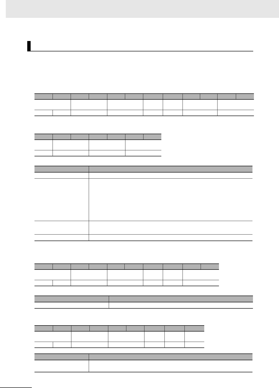
Classification Command
Options
Reserved
Diag-
nostic
results
Reserved RSSI EPC
Bits 5 to
15 Bit 4 Bits 2
and 3 Bit 1 Bit 0
Communications
command, multi-
access
SET MULTIACCESS ID READ --- No --- OK No
SET MULTIACCESS DATA READ --- No --- OK OK
7 Modbus/TCP Communications
7 - 10 UHF RFID System V780-series Reader/Writer User’s Manual (Z389)
Communications
command, Mod-
bus expansion
EXTENDED DATA READ --- OK --- OK OK
EXTENDED DATA WRITE --- OK --- OK OK
EXTENDED MULTIACCESS ID
READ
--- No --- OK No
EXTENDED MULTIACCESS DATA
READ
--- No --- OK OK
Classification Command
Options
Reserved
Diag-
nostic
results
Reserved RSSI EPC
Bits 5 to
15 Bit 4 Bits 2
and 3 Bit 1 Bit 0
7 - 11
7 Modbus/TCP Communications
UHF RFID System V780-series Reader/Writer User’s Manual (Z389)
7-4 Communications Procedure
7
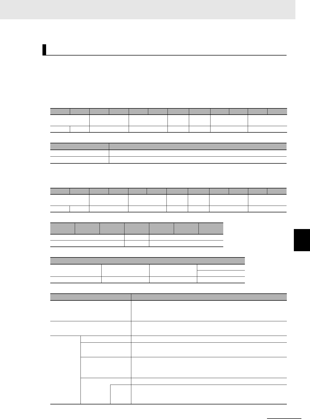
7-4-1 Command Communications Procedure
7-4 Communications Procedure
In the computer, PLC, or other host devices, write the program to communicate with the Reader/Writer
using TCP sockets.
If you use an Modbus/TCP master device, follow the communications procedure for the device you are
using.
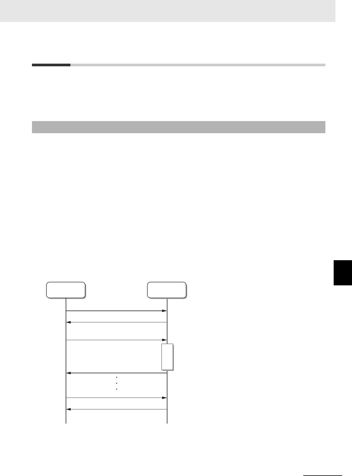
A connection is required between the host device and Reader/Writer to communicate with the
Reader/Writer. After you establish a connection, send commands and receive the responses.
1Connection Processing: Opening a Socket
Send a request for a connection from the host device to the Reader/Writer and establish a TCP
connection. Monitor for connection timeouts as required.
2Command Send Processing: Sending Socket Data
Send the command from the host device to the Reader/Writer in a message.
Monitor for send timeouts as required.
3Response Reception Processing: Receiving Socket Data
At the host device, wait to receive the message from the host device and receive the response.
Monitor for reception timeouts as required.
4Disconnection Processing: Closing the Socket
Send a request for a disconnection from the host device to the Reader/Writer and disconnect
the TCP connection. Monitor for disconnection timeouts as required.
7-4-1 Command Communications Procedure
Host device
(client)
Reader/Writer
(server)
Connection requested.
Connection request acknowledged.
Disconnection requested.
Disconnection request acknowledged.
Command sent.
Response returned.
Command
execution
7 Modbus/TCP Communications
7 - 12 UHF RFID System V780-series Reader/Writer User’s Manual (Z389)
Precautions for Correct Use
Access to a Reader/Writer is possible from only one host device at a time.
If a host device B connects to a Reader/Writer while another host device A is already con-
nected to it, the connection between host device A and the Reader/Writer will be automatically
disconnected and a connection with host device B will be established.
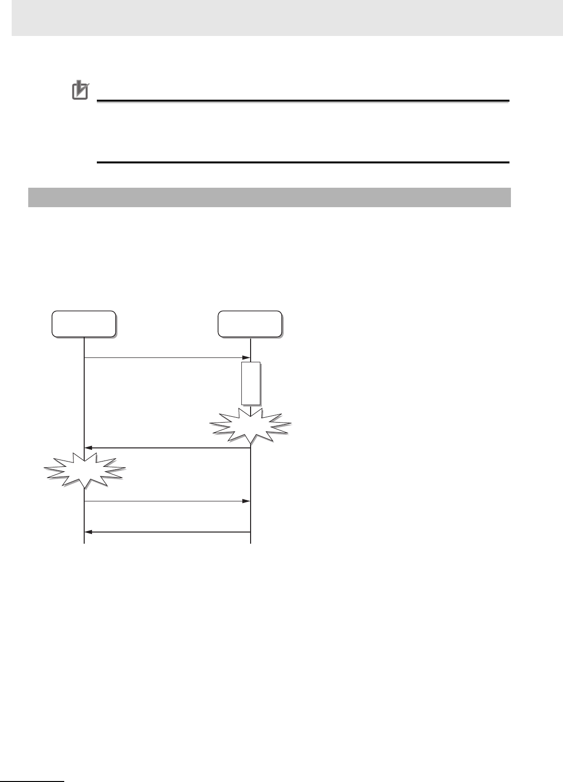
If an error response is received, you can check the most recent command error information or com-
mand error log in the Reader/Writer to get details on the nature of the error. An error has occurred if the
function code in the response that was returned from the Reader/Writer is 80 hex higher than the func-
tion code in the query.
You can do this by sending a GET MOST RECENT ERROR INFORMATION command or GET COM-
MAND ERROR LOG command from the host device or by using the Web browser interface through the
Web server.
7-4-2 Error Response Reception Procedure
Error
occurs.
Error
detected.
Host device
(client)
Reader/Writer
(server)
Command
execution
GET MOST RECENT ERROR
INFORMATION command sent.
(Or, GET COMMAND ERROR LOG command sent.)
Error information returned.
Command sent.
Response returned.
Function code + 80 hex
7 - 13
7 Modbus/TCP Communications
UHF RFID System V780-series Reader/Writer User’s Manual (Z389)
7-4 Communications Procedure
7
7-4-3 RF Tag Communications Command Procedure for Single-access Communica-
tions
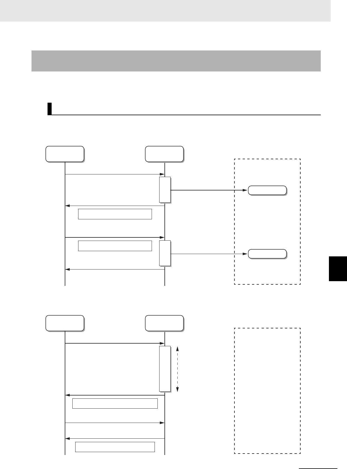
When you send an RF Tag communications command with single-access communications, the
Reader/Writer communicates with only one RF Tag in the communications field.
With a normal command, the maximum size of data that you can read from an RF Tag is 120 words. To
read more data than that, you must use more than one READ DATA or WRITE DATA command, or use
an expanded command.
If communications with an RF Tag are not possible, a “failure in slave device” exception code (04 hex)
is returned in an error response. Following the error response reception procedure.
7-4-3 RF Tag Communications Command Procedure for Single-access
Communications
Using a Normal Command (FC03 or FC16)
Host device
(client)
Reader/Writer
(server)
RF Tag A
RF Tag A
Command
execution
Command
execution
READ DATA communications
command sent.
Communications field
RF Tag memory
read/written.
RF Tag memory
read/written.
WRITE DATA communications
command sent.
Read data (120 words max.)
Data to write (120 words max.)
Response returned.
Response returned.
Host device
(client)
Reader/Writer
(server)
Command
execution
READ DATA communications
command sent.
Communications field
GET MOST RECENT ERROR INFORMATION
command sent.
Exception code: Failure in slave device
Error code: RF Tag missing error
Response returned.
Timeout (TMO)
Error information returned.
7 Modbus/TCP Communications
7 - 14 UHF RFID System V780-series Reader/Writer User’s Manual (Z389)
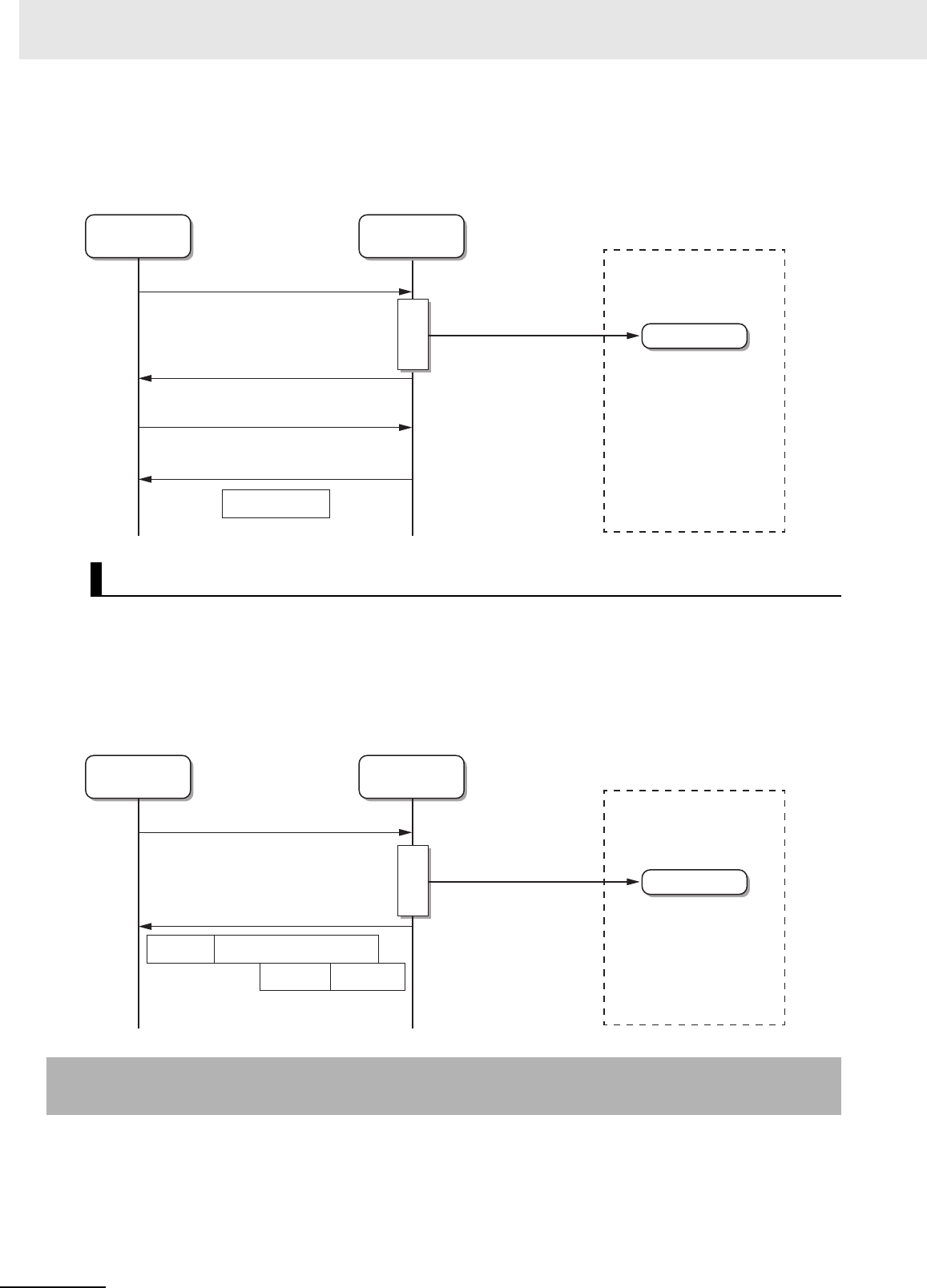
If you want to check the EPC code or reception level when communications with the RF Tag are suc-
cessful, send a GET RF TAG ADDITIONAL INFORMATION command after the response to the com-
munications command has been received. The reception level from the RF Tag that was just
communicated with will be returned.
With an expanded command, the maximum size of data that you can read from an RF Tag is 2,048
words.
If an error occurs in the RF Tag communications, the error code is returned with the response. No addi-
tional command is required to check the error code.
You can also specify a command option to have the EPC code or reception level returned with the other
data.
When you send an RF Tag communications command with multiaccess communications, the
Reader/Writer communicates with more than one RF Tag in the communications field.
The Reader/Writer will communicate with all of the RF Tags in the communications field within the com-
munications timeout time (64 max.) and then return a response.
Using an Expanded Command (FC100)
7-4-4 RF Tag Communications Command Procedure for Multiaccess
Communications
Host device
(client)
Reader/Writer
(server)
RF Tag A
Command
execution
READ DATA communications
command sent.
Communications field
RF Tag memory
read/written.
GET RF TAG ADDITIONAL
INFORMATION command sent.
Reception level
Response returned.
Response returned.
Host device
(client)
Reader/Writer
(server)
RF Tag A
Command
execution
EXPANDED DATA READ
communications command sent.
Communications field
RF Tag memory
read/written.
Error code
+ EPC code
+ Reception level
Read data (2,048 words max.)
Response returned
(2,048 words max.)
7 - 15
7 Modbus/TCP Communications
UHF RFID System V780-series Reader/Writer User’s Manual (Z389)
7-4 Communications Procedure
7
7-4-4 RF Tag Communications Command Procedure for Multiaccess Communica-
tions
With a normal multiaccess RF Tag command, two commands are used to exchange the data, one to set
communications and another to get the results.
1Sending the Command to Set Communications
First, send the command to set communications.
If the Reader/Writer detects even one RF Tag, the results of execution are returned as a normal
response.
If no RF Tags were detected, an RF Tag missing error is returned.
2Sending the Command to Get the Results
Send the command to get the results.
When you execute the command to get the results, the results of communications with the first
RF Tag that was detected will be returned. The communications results will contain the number
of RF Tags detected, the error code, and, for READ DATA, the EPC code.
If the option is specified, the reception level information is also attached.
3Repeatedly Getting the Results
Execute the command to get the results once for every RF Tag that was detected.
The number of RF Tags that was detected by the Reader/Writer is included in the response to
the command to get the results. Repeatedly send the command until the number of RF Tags in
the response is 1.
Using a Normal Command (FC03 or FC16)
Host device
(client)
Reader/Writer
(server)
RF Tag A
RF Tag B
RF Tag C
SET MULTIACCESS DATA READ
communications command sent.
GET MULTIACCESS DATA READ RESULTS communications command sent.
GET MULTIACCESS DATA READ RESULTS communications command sent.
Communications field
RF Tag memory
read/written.
Error code Read data
Number of RF Tags: 3
EPC code
+ Reception level
Error code Read data
Number of RF Tags: 2
EPC code
+ Reception level
Response returned.
Response returned.
Response returned.
GET MULTIACCESS DATA READ RESULTS communications command sent.
Error code Read data
Number of RF Tags: 1
EPC code
+ Reception level
Response returned.
Command execution
Timeout (TMO)
RF Tag A
communications
results
RF Tag B
communications
results
RF Tag C
communications
results
7 Modbus/TCP Communications
7 - 16 UHF RFID System V780-series Reader/Writer User’s Manual (Z389)
Precautions for Correct Use
If you execute another communications command (e.g., a single-access read, write, or fill com-
mand or a multiaccess read command) before you execute the commands to get the results,
the multiaccess communications results held in the Reader/Writer will be cleared.
With an expanded command, you can execute one multiaccess RF Tag command to get the communi-
cations results from more than one RF Tag with only one command.
Precautions for Correct Use
The normal MULTIACCESS DATA READ and MULTIACCESS ID READ communications com-
mands are designed for applications that read two to five RF Tags at one time. If your applica-
tion requires reading more RF Tags than that, we recommend that you use an expanded
command.
Using an Expanded Command (FC100)
Host device
(client)
Reader/Writer
(server)
RF Tag A
RF Tag B
RF Tag C
SET MULTIACCESS DATA READ
communications command sent.
Communications field
RF Tag memory
read/written.
Error code Read data
Number of RF Tags: 3
EPC code
+ RSSI level
Error code Read dataEPC code
+ RSSI level
Response returned.
Response returned.
Error code Read dataEPC code
+ RSSI level
Command execution
Timeout
(TMO)
RF Tag A
communications results
RF Tag B
communications results
RF Tag C
communications results
7 - 17
7 Modbus/TCP Communications
UHF RFID System V780-series Reader/Writer User’s Manual (Z389)
7-5 Commands
7
7-5 Commands
The commands that you can send to a Reader/Writer are listed below.
The command codes are used to identify the commands and they are recorded in the most recent com-
mand error information and command error log with an error response is returned. (This information is
not included in the Modbus/TCP message format.)
Single-access Communications Commands
Command name Function code Register address Command code
READ ID FC03 4000 hex 0001 hex
WRITE ID FC16 4000 hex 0002 hex
READ DATA FC03 0000 to 07FF hex
1000 to 17FF hex
2000 to 27FF hex
3000 to 3FFF hex*1
0003 hex
WRITE DATA FC16 0000 to 07FF hex
1000 to 17FF hex
2000 to 27FF hex
3000 to 3FFF hex
0004 hex
LOCK FC16 8000 hex 0005 hex
DATA FILL FC16 8100H hex 0006 hex
Multiaccess Communications Commands
Command name Function code Register address Command code
SET MULTIACCESS ID READ FC16 Always 9000 hex. 0101 hex
GET MULTIACCESS ID READ
RESULTS
FC03 Always 9100 hex. 0102 hex
SET MULTIACCESS DATA READ FC16 Always 9200 hex. 0103 hex
GET MULTIACCESS DATA READ
RESULTS
FC03 Always 9300 hex. 0104 hex
Modbus Expansion Communications Commands
Command name Function code Subfunction code Command code
EXTENDED DATA READ FC100 0001 hex 0201 hex
EXTENDED DATA WRITE FC100 0002 hex 0202 hex
EXTENDED MULTIACCESS ID READ FC100 0003 hex 0203 hex
EXTENDED MULTIACCESS DATA
READ
FC100 0004 hex 0204 hex
7 Modbus/TCP Communications
7 - 18 UHF RFID System V780-series Reader/Writer User’s Manual (Z389)
Reader/Writer Control Commands
Command name Function code Register address Command code
INITIALIZE FC16 A000 hex 1001 hex
RESET FC16 A100 hex 1002 hex
STOP FC16 A200 hex 1003 hex
RESET FOCUS FC16 A300 hex 1004 hex
Reader/Writer Setting Commands: Network Settings
Command name Function code Register address Command code
SET TCP/IP COMMUNICATIONS
CONDITIONS
FC16 B000 hex 2001 hex
GET TCP/IP COMMUNICATIONS
CONDITIONS
FC03 B000H hex 2002 hex
SET DEVICE NAME FC16 B100 hex 2003 hex
GET DEVICE NAME FC03 B100 hex 2004 hex
SET MODBUS/TCP COMMUNICA-
TIONS CONDITIONS
FC16 B200 hex 2005 hex
GET MODBUS/TCP COMMUNICA-
TIONS CONDITIONS
FC03 B200 hex 2006 hex
SET WEB COMMUNICATIONS
CONDITIONS
FC16 B300 hex 2007 hex
GET WEB COMMUNICATIONS
CONDITIONS
FC03 B300 hex 2008 hex
SET WEB PASSWORD FC16 B400 hex 2009 hex
GET WEB PASSWORD FC03 B400 hex 200A hex
Reader/Writer Setting Commands: Device Settings
Command name Function code Register address Command code
SET OPERATION INDICATOR
CUSTOM CONDITIONS
FC16 B800 hex 5001 hex
GET OPERATION INDICATOR
CUSTOM CONDITIONS
FC03 B800 hex 5002 hex
Reader/Writer Setting Commands: Communications Settings
Command name Function code Register address Command code
SET TAG COMMUNICATIONS
CONDITIONS
FC16 C000 hex 3001 hex
GET TAG COMMUNICATIONS
CONDITIONS
FC03 C000 hex 3002 hex
SET TRANSMISSION POWER FC16 C100 hex 3003 hex
GET TRANSMISSION POWER FC03 C100 hex 3004 hex
SET CHANNEL FC16 C200 hex 3005 hex
GET CHANNEL FC03 C200 hex 3006 hex
SET GEN2 SESSION FC16 C300 hex 3007 hex
7 - 19
7 Modbus/TCP Communications
UHF RFID System V780-series Reader/Writer User’s Manual (Z389)
7-5 Commands
7
7-4-4 RF Tag Communications Command Procedure for Multiaccess Communica-
tions
GET GEN2 SESSION FC03 C300 hex 3008 hex
SET ACCESS PASSWORD FC16 C400 hex 3009 hex
GET ACCESS PASSWORD FC03 C400 hex 300A hex
SET RF TAG SELECTION FILTER
CONDITIONS
FC16 C500 hex 300B hex
GET RF TAG SELECTION FILTER
CONDITIONS
FC03 C500 hex 300C hex
SET RSSI FILTER CONDITIONS FC16 C600 hex 300D hex
GET RSSI FILTER CONDITIONS FC03 C600 hex 300E hex
SET TRANSMISSION TIME FC16 C700 hex 300F hex
GET TRANSMISSION TIME FC03 C700 hex 3010 hex
Maintenance Commands: Device Information
Command name Function code Register address Command code
GET MODEL INFORMATION FC03 D000 hex 4001 hex
GET FIRMWARE VERSION FC03 D100 hex 4002 hex
GET MAC ADDRESS FC03 D200 hex 4003 hex
GET OPERATING STATUS FC03 D300 hex 4004 hex
GET TIME INFORMATION FC03 D400 hex 4005 hex
SET TIME INFORMATION FC16 D400 hex 4006 hex
Maintenance Commands: Log Information
Command name Function code Register address Command code
GET SYSTEM ERROR LOG FC03 D600 hex 4101 hex
CLEAR SYSTEM ERROR LOG FC16 D700 hex 4102 hex
GET COMMAND ERROR LOG FC03 D800 hex 4103 hex
GET MOST RECENT COMMAND
ERROR INFORMATION
FC03 D900 hex 4104 hex
Maintenance Commands: RF Communications Information
Command name Function code Register address Command code
GET RF TAG ADDITIONAL INFOR-
MATION
FC03 DA00 hex 4201 hex
GET NOISE LEVEL FC03 DB00 hex 4202 hex
GET COMMUNICATIONS DIAG-
NOSTIC INFORMATION
FC03 DC00 hex 4203 hex
Command name Function code Register address Command code
7 Modbus/TCP Communications
7 - 20 UHF RFID System V780-series Reader/Writer User’s Manual (Z389)
7-6 V780 Command Details
Function
This command reads the ID (i.e., the EPC code) of the RF Tag in the communications field.
Command Format
Response Formats
• Normal Response
Note If the reception level is required, use GET RF TAG ADDITIONAL INFORMATION on page 7-121.
Additional Information
• StoredPC Bit Format
7-6-1 Single-access Communications Commands
READ ID
Byte-0 Byte-1 Byte-2 Byte-3 Byte-4 Byte-5 Byte-6 Byte-7 Byte-8 Byte-9 Byte-10 Byte-11
Transaction identi-
fier
Protocol identifier Field length Unit
identifier
Function
code
Register address Word count
X X 0000 hex 0006 hex FF hex 03 hex 4000 hex 0020 hex
Parameter Description
Register address The register address (4000 hex) that specifies reading the ID
Word count The number of words in the read StoredPC and EPC code (always 0020 hex).
Byte-0 Byte-1 Byte-2 Byte-3 Byte-4 Byte-5 Byte-6 Byte-7 Byte-8 Byte-9 Byte-10
Transaction identi-
fier
Protocol identifier Field length Unit
identifier
Function
code
Byte
count
StoredPC
X X 0000 hex 0043 hex FF hex 03 hex 40 hex 2 bytes
Byte-11 …Byte-72
EPC code
62 bytes
Parameter Description
StoredPC Gives the StoredPD data in 4-digit hexadecimal.
The upper 5 bits are the EPC word length. (Refer to StoredPC Bit Format on page
20, below.)
EPC code Gives the Tag-specific information according to Gen2 standards.
All bytes of the EPC code section that exceed the EPC word length in the StoredPC
are filled with 00 hex.
10 11 12 13 14 15 16 17 18 19 1A 1B 1C 1D 1E 1F
PC + EPC length
16 x (n + 1)
RFU 0:EPS
1:AFI
Data

7 - 21
7 Modbus/TCP Communications
UHF RFID System V780-series Reader/Writer User’s Manual (Z389)
7-6 V780 Command Details
7
7-6-1 Single-access Communications Commands
• Error Response
Execution Examples
Reading the ID Data from the RF Tagt
Example 1: Execution When an RF Tag Is in the Communications Field (StoredPC: 3000 hex, EPC
code: 111122223333444455556666 hex)
TX: 000000000006FF0340000020
RX: 000000000043FF0340300011112222333344445555666600…00
* Words 7 through 31 of the EPC code section (i.e., the words past the EPC length of 6 words) are
filled with zeros.
Example 2: Execution When an RF Tag Is Not in the Communications Field (Exception Code: 04
Hex (Failure in Device))
TX: 000000000006FF0340000020
RX: 000000000003FF8304
Byte-0 Byte-1 Byte-2 Byte-3 Byte-4 Byte-5 Byte-6 Byte-7 Byte-8
Transaction identi-
fier
Protocol identifier Field length Unit
identifier
Function
code
Excep-
tion
code
X X 0000 hex 0003 hex FF hex 83 hex 1 byte
Parameter Description
Exception code For details, refer to Exception Code on page 7-7 under Response Format for Error
Completion on page 7-7.
7 Modbus/TCP Communications
7 - 22 UHF RFID System V780-series Reader/Writer User’s Manual (Z389)
Function
This command writes the ID (i.e., the EPC code) to the RF Tag in the communications field.
Command Format
Response Formats
• Normal Response
Note If the reception level is required, use GET RF TAG ADDITIONAL INFORMATION on page 7-121.
• Error Response
WRITE ID
Byte-0 Byte-1 Byte-2 Byte-3 Byte-4 Byte-5 Byte-6 Byte-7 Byte-8 Byte-9 Byte-10 Byte-11
Transaction identi-
fier
Protocol identifier Field length Unit
identifier
Function
code
Register address Word count
X X 0000 hex 2 bytes FF hex 10 hex 4000 hex 2 bytes
Byte-12 Byte-13 Byte-14 Byte-15 …Byte-n
Byte
count
EPC length EPC code
1 byte 2 bytes 0 to 62 bytes
Parameter Description
Field length Setting range: 0015 to 0047 hex
Register address The register address (4000 hex) that specifies reading or writing the ID
Word count Setting range: 0001 to 0020 hex
Byte count Setting range: 02 to 40 hex
EPC length Gives the word size of the EPC code in 4-digit hexadecimal.
0000 to 001F hex (0 to 32)
EPC code Gives the Tag-specific information according to Gen2 standards.
Byte-0 Byte-1 Byte-2 Byte-3 Byte-4 Byte-5 Byte-6 Byte-7 Byte-8 Byte-9 Byte-10 Byte-11
Transaction identi-
fier
Protocol identifier Field length Unit
identifier
Function
code
Register address Word count
X X 0000 hex 0006 hex FF hex 10 hex 2 bytes 2 bytes
Parameter Description
Register address The register address from the command is set
Word count The word count from the command is set.
Byte-0 Byte-1 Byte-2 Byte-3 Byte-4 Byte-5 Byte-6 Byte-7 Byte-8
Transaction identi-
fier
Protocol identifier Field length Unit
identifier
Function
code
Excep-
tion
code
X X 0000 hex 0003 hex FF hex 90 hex 1 byte
Parameter Description
Exception code For details, refer to Exception Code on page 7-7 under Response Format for Error
Completion on page 7-7.

7 - 23
7 Modbus/TCP Communications
UHF RFID System V780-series Reader/Writer User’s Manual (Z389)
7-6 V780 Command Details
7
7-6-1 Single-access Communications Commands
Execution Examples
Writing the ID Data to an RF Tag (EPC Length: 0006 Hex, EPC Code: 111122223333444455556666
Hex)
TX: 000000000015FF10400000070E0006111122223333444455556666
RX: 000000000006FF1040000007
7 Modbus/TCP Communications
7 - 24 UHF RFID System V780-series Reader/Writer User’s Manual (Z389)
Function
This command reads data from the RF Tag in the communications field.
Command Format
Response Formats
• Normal Response
Note If the reception level is required, use GET RF TAG ADDITIONAL INFORMATION on page 7-121.
• Error Response
READ DATA
Byte-0 Byte-1 Byte-2 Byte-3 Byte-4 Byte-5 Byte-6 Byte-7 Byte-8 Byte-9 Byte-10 Byte-11
Transaction identi-
fier
Protocol identifier Field length Unit
identifier
Function
code
Register address Word count
X X 0000 hex 0006 hex FF hex 03 hex 2 bytes 2 bytes
Parameter Description
Register address Specify in 4-digit hexadecimal the start address for reading data.
Setting ranges (word address specifications)
0000 to 07FF hex: Reserved area
1000 to 17FF hex: EPC area
2000 to 27FF hex: TID area
3000 to 37FF hex: User area
Word count Specify in 4-digit hexadecimal the number of words of data to read.
Setting range: 0001 to 0078 hex (1 to 120)
Byte-0 Byte-1 Byte-2 Byte-3 Byte-4 Byte-5 Byte-6 Byte-7 Byte-8 Byte-9 …Byte-n
Transaction identi-
fier
Protocol identifier Field length Unit
identifier
Function
code
Byte
count
Read data
X X 0000 hex 00 hex 1 byte FF hex 03 hex 1 byte 2 to 240 bytes
Parameter Description
Byte count Contains the number of bytes of data that were read from the RF Tag in 2-digit hexa-
decimal. (02 to F0 hex)
Read data The data that was read from the RF Tag is attached.
Byte-0 Byte-1 Byte-2 Byte-3 Byte-4 Byte-5 Byte-6 Byte-7 Byte-8
Transaction identi-
fier
Protocol identifier Field length Unit iden-
tifier
Function
code
Excep-
tion code
X X 0000 hex 0003 hex FF hex 83 hex 1 byte
Parameter Description
Exception code For details, refer to Exception Code on page 7-7 under Response Format for Error
Completion on page 7-7.

7 - 25
7 Modbus/TCP Communications
UHF RFID System V780-series Reader/Writer User’s Manual (Z389)
7-6 V780 Command Details
7
7-6-1 Single-access Communications Commands
Execution Examples
Reading Four Words of Data (1111222233334444 Hex) Starting from Word Address 0123 Hex (User
Area) in the RF Tag
TX: 000000000006FF0331230004
RX: 000000000013FF03081111222233334444
7 Modbus/TCP Communications
7 - 26 UHF RFID System V780-series Reader/Writer User’s Manual (Z389)
Function
This command writes data to the RF Tag in the communications field.
Command Format
Response Formats
• Normal Response
Note If the reception level is required, use GET RF TAG ADDITIONAL INFORMATION on page 7-121.
• Error Response
WRITE DATA
Byte-0 Byte-1 Byte-2 Byte-3 Byte-4 Byte-5 Byte-6 Byte-7 Byte-8 Byte-9 Byte-1
0Byte-11
Transaction identi-
fier
Protocol identifier Field length Unit
identifier
Function
code
Register address Word count
X X 0000 hex 2 bytes FF hex 10 hex 2 bytes 2 bytes
Byte-12 Byte-13 …Byte-n
Byte
count
Data to write
1 byte 1 to 120 words
Parameter Description
Field length Setting range: 0009 to 00F7 hex (9 to 247)
Register address Specify in 4-digit hexadecimal the start address for writing data in the RF Tag.
Setting ranges (word address specifications)
0000 to 07FF hex: Reserved area
1000 to 17FF hex: EPC area
2000 to 27FF hex: TID area
3000 to 37FF hex: User area
Word count Specify in 4-digit hexadecimal the number of words of data to write.
Setting range: 0001 to 0078 hex (120 words max.)
Byte count Specify in 4-digit hexadecimal the number of bytes of data to write.
Setting range: 02 to F0 hex (240 bytes max.)
Data to write Specify the data to write to RF Tag.
Between 1 and 120 words of data can be written with one command.
Byte-0 Byte-1 Byte-2 Byte-3 Byte-4 Byte-5 Byte-6 Byte-7 Byte-8 Byte-9 Byte-10 Byte-11
Transaction identi-
fier
Protocol identifier Field length Unit
identifier
Function
code
Register address Word count
X X 0000 hex 0006 hex FF hex 10 hex 2 bytes 2 bytes
Parameter Description
Register address The register address from the command is set
Word count The word count from the command is set.
Byte-0 Byte-1 Byte-2 Byte-3 Byte-4 Byte-5 Byte-6 Byte-7 Byte-8
Transaction identi-
fier
Protocol identifier Field length Unit
identifier
Function
code
Excep-
tion code
X X 0000 hex 0003 hex FF hex 90 hex 1 byte

7 - 27
7 Modbus/TCP Communications
UHF RFID System V780-series Reader/Writer User’s Manual (Z389)
7-6 V780 Command Details
7
7-6-1 Single-access Communications Commands
Execution Examples
Writing Four Words of Data (1111222233334444 Hex) Starting from Word Address 0123 Hex (User
Area) in the RF Tag
TX: 00000000000FFF1031230004081111222233334444
RX: 000000000006FF1031230004
Parameter Description
Exception code For details, refer to Exception Code on page 7-7 under Response Format for Error
Completion on page 7-7.
7 Modbus/TCP Communications
7 - 28 UHF RFID System V780-series Reader/Writer User’s Manual (Z389)
Function
This command locks or unlocks the memory of the RF Tag in the communications field.
Command Format
Note 1. When an area is locked, the specified password is written to the access password area in the RF Tag.
2. If an address error, lock error, or RF Tag system error occurs when locking an area, the access pass-
word area in the RF Tag will be cleared to all zeros.
3. When an RF Tag is unlocked, the access password area in the RF Tag will be cleared to all zeros.
Response Formats
• Normal Response
LOCK
Byte-0 Byte-1 Byte-2 Byte-3 Byte-4 Byte-5 Byte-6 Byte-7 Byte-8 Byte-9 Byte-10 Byte-11
Transaction identi-
fier
Protocol identifier Field length Unit
identifier
Function
code
Register address Word count
X X 0000 hex 000F hex FF hex 10 hex 8000F hex 0004 hex
Byte-12 Byte-13 Byte-14 Byte-15 Byte-16 Byte-17 …Byte-20
Byte
count
Lock operation Area to lock/unlock Password
08 hex 2 bytes 2 bytes 4 bytes
Parameter Description
Lock operation Specify locking or unlocking.
0000 hex: Unlock
0001 hex: Lock
• If you specify locking the EPC, TID, or user area, you will no longer be able to write data to
that area.
• If you specify locking the access password, you will no longer be able to read the access
password area.
• When you unlock an area, specify all of the areas that have been locked.
Area to
lock/unlock
Specify one or more of the EPC, TID, and user areas.
EPC area: 0001 hex
TID area: 0002 hex
User area: 0004 hex
Access password: 0008 hex
• If all zeros is specified, a command parameter error will occur.
Password Specify the access password to set in the Tag in 8-digit hexadecimal (32 bits) (00000000 hex).
Locking: The access password to set in the RF Tag to lock.
Unlocking: The access password in the RF Tag to unlock.
Byte-0 Byte-1 Byte-2 Byte-3 Byte-4 Byte-5 Byte-6 Byte-7 Byte-8 Byte-9 Byte-10 Byte-11
Transaction identi-
fier
Protocol identifier Field length Unit
identifier
Function
code
Register address Word count
X X 0000 hex 0006 hex FF hex 10 hex 2 bytes 2 bytes
Parameter Description
Register address The register address from the command is set
Word count The word count from the command is set.
7 - 29
7 Modbus/TCP Communications
UHF RFID System V780-series Reader/Writer User’s Manual (Z389)
7-6 V780 Command Details
7
7-6-1 Single-access Communications Commands
Note If the reception level is required, use GET RF TAG ADDITIONAL INFORMATION on page 7-121.
• Error Response
Execution Examples
Example 1: Locking the User Area of the RF Tag with a Password of 12345678 Hex
TX: 00000000000FFF1080000004080001000412345678
RX: 000000000006FF1080000004
Example 2: Unlocking the User Area
TX: 00000000000FFF1080000004080000000412345678
RX: 000000000006FF1080000004
Byte-0 Byte-1 Byte-2 Byte-3 Byte-4 Byte-5 Byte-6 Byte-7 Byte-8
Transaction identi-
fier
Protocol identifier Field length Unit
identifier
Function
code
Excep-
tion code
X X 0000 hex 0003 hex FF hex 90 hex 1 byte
Parameter Description
Exception code For details, refer to Exception Code on page 7-7 under Response Format for Error
Completion on page 7-7.
7 Modbus/TCP Communications
7 - 30 UHF RFID System V780-series Reader/Writer User’s Manual (Z389)
Function
This command writes the specified data to the specified number of words beginning from the speci-
fied write start address. The specifications are made in the command.
Command Format
Response Formats
• Normal Response
Note If the reception level is required, use GET RF TAG ADDITIONAL INFORMATION on page 7-121.
DATA FILL
Byte-0 Byte-1 Byte-2 Byte-3 Byte-4 Byte-5 Byte-6 Byte-7 Byte-8 Byte-9 Byte-10 Byte-11
Transaction identi-
fier
Protocol identifier Field length Unit
identifier
Function
code
Register address Word count
X X 0000 hex 000D hex FF hex 10 hex 8100 hex 0003 hex
Byte-12 Byte-13 Byte-14 Byte-15 Byte-16 Byte-17 Byte-18
Byte
count
Fill information
Fill address Number of fill
words
Fill data
06 hex 2 bytes 2 bytes 2 bytes
Parameter Description
Register address The register address (8100 hex) that specifies filling data
Word count Number of words of fill information (0003 hex)
Byte count Number of bytes of fill information (06 hex)
Fill information Fill address Specify in 4-digit hexadecimal the start address for writing data in the RF
Tag .
0000 to 07FF hex: Reserved area
1000 to 17FF hex: EPC area
2000 to 27FF hex: TID area
3000 to 37FF hex: User area
Number of fill
words
Specify in 4-digit hexadecimal the number of words of data to fill.
Setting range: 0000 hex or 0001 to 0800 hex
• If 0000 hex is specified for the number of fill words, the entire memory
area will be filled.
• You cannot write data to more than one area with the same command.
Fill data Specify in 4-digit hexadecimal the data to write to the RF Tag.
Byte-0 Byte-1 Byte-2 Byte-3 Byte-4 Byte-5 Byte-6 Byte-7 Byte-8 Byte-9 Byte-10 Byte-11
Transaction identi-
fier
Protocol identifier Field length Unit
identifier
Function
code
Register address Word count
X X 0000 hex 0006 hex FF hex 10 hex 2 bytes 0003 hex
Parameter Description
Register address The register address from the command is set
Word count The word count from the command is set.

7 - 31
7 Modbus/TCP Communications
UHF RFID System V780-series Reader/Writer User’s Manual (Z389)
7-6 V780 Command Details
7
7-6-1 Single-access Communications Commands
• Error Response
Execution Examples
Example 1: Writing 5A5A Hex to Four Words Starting from Word Address 0100 Hex (User Area) in
the RF Tag
TX: 00000000000DFF108100000306310000045A5A
RX: 000000000006FF1081000003
Example 2: Writing 5A5A Hex to the Entire User Area in the RF Tag
TX: 00000000000DFF108100000306300000005A5A
RX: 000000000006FF1081000003
Byte-0 Byte-1 Byte-2 Byte-3 Byte-4 Byte-5 Byte-6 Byte-7 Byte-8
Transaction identi-
fier
Protocol identifier Field length Unit
identifier
Function
code
Excep-
tion code
X X 0000 hex 0003 hex FF hex 90 hex 1 byte
Parameter Description
Exception code For details, refer to Exception Code on page 7-7 under Response Format for Error
Completion on page 7-7.
7 Modbus/TCP Communications
7 - 32 UHF RFID System V780-series Reader/Writer User’s Manual (Z389)
Function
This command specifies reading the IDs (i.e., the ECP codes) of the RF Tags in the communications
field.
Command Format
Response Formats
• Normal Response
• Error Response
7-6-2 Multiaccess Communications Commands
SET MULTIACCESS ID READ
Byte-0 Byte-1 Byte-2 Byte-3 Byte-4 Byte-5 Byte-6 Byte-7 Byte-8 Byte-9 Byte-10 Byte-11
Transaction identi-
fier
Protocol identifier Field length Unit
identifier
Function
code
Register address Word count
X X 0000 hex 0009 hex FF hex 10 hex 9000F hex 0001 hex
Byte-12 Byte-13 Byte-14
Byte
count
Options
02 hex 2 bytes
Parameter Description
Register address The register address (9000 hex) that specifies setting multiaccess ID reading
Word count The number of words for the option (0001 hex)
Byte count The number of option bytes (02 hex)
Options For details, refer to 7-3 RF Communications Command Options on page 7-9.
Options are implemented in a normal response to the GET MULTIACCESS ID
READ RESULTS on page 7-33.
Byte-0 Byte-1 Byte-2 Byte-3 Byte-4 Byte-5 Byte-6 Byte-7 Byte-8 Byte-9
Transaction identi-
fier
Protocol identifier Field length Unit
identifier
Function
code
Word count
X X 0000 hex 0004 hex FF hex 10 hex 0001 hex
Parameter Description
Word count Always 0001 hex.
Byte-0 Byte-1 Byte-2 Byte-3 Byte-4 Byte-5 Byte-6 Byte-7 Byte-8
Transaction identi-
fier
Protocol identifier Field length Unit
identifier
Function
code
Excep-
tion code
X X 0000 hex 0003 hex FF hex 90 hex 1 byte
Parameter Description
Exception code For details, refer to Exception Code on page 7-7 under Response Format for Error
Completion on page 7-7.
7 - 33
7 Modbus/TCP Communications
UHF RFID System V780-series Reader/Writer User’s Manual (Z389)
7-6 V780 Command Details
7
7-6-2 Multiaccess Communications Commands
Execution Examples
Specifying Multiaccess Reading of the IDs by the Reader/Writer with No Options
Example 1: Execution when an RF Tag Is in the Communications Field
TX: 000000000009FF1090000001020000
RX: 000000000004FF100001
Example 2: Execution When an RF Tag Is Not in the Communications Field (Exception Code: 04
Hex (Failure in Device))
TX: 000000000009FF1090000001020000
RX: 000000000003FF9004
Function
This command reads data from the RF Tag in the communications field.
You can specify reading up to 2,048 words with one GET MULTIACCESS ID READ RESULTS com-
mand.
Command Format
Response Formats
• Normal Response
GET MULTIACCESS ID READ RESULTS
Byte-0 Byte-1 Byte-2 Byte-3 Byte-4 Byte-5 Byte-6 Byte-7 Byte-8 Byte-9 Byte-10 Byte-11
Transaction identi-
fier
Protocol identifier Field length Unit
identifier
Function
code
Register address Word count
X X 0000 hex 0006 hex FF hex 03 hex 9100F hex 2 bytes
Parameter Description
Register address The register address (9100 hex) that specifies getting the results of multiaccess ID
reading
Word count 0022 hex + Option size
• For details on option sizes, refer to 7-3 RF Communications Command Options
on page 7-9.
Byte-0 Byte-1 Byte-2 Byte-3 Byte-4 Byte-5 Byte-6 Byte-7 Byte-8 Byte-9 Byte-10
Transaction identi-
fier
Protocol identifier Field length Unit
identifier
Function
code
Byte
count
Number of RF
Tags
X X 0000 hex 2 bytes FF hex 03 hex 1 byte 2 bytes
Byte-11 Byte-12 Byte-13 Byte-14 Byte-15 ... Byte-76 Byte-77 Byte-78
Error code StoredPC EPC code Options
Reception level
2 bytes 2 bytes 62 bytes 2 bytes
7 Modbus/TCP Communications
7 - 34 UHF RFID System V780-series Reader/Writer User’s Manual (Z389)
• Error Response
Execution Examples
Specifying Getting the Results of Multiaccess Reading of the IDs by the Reader/Writer with No
Options
There are three RF Tags in the communications field.
Getting the First Results (Getting the Communications Results for RF Tag A)
TX: 000000000006FF0391000022
RX: 000000000047FF0344000300003000AAAA…AAAA0000…0000
Parameter Description
Field length Gives the total number of bytes starting from the unit identifier in 4-digit
hexadecimal.
0047 hex + Option size
• For details on option sizes, refer to 7-3 RF Communications Command
Options on page 7-9.
Byte count Gives the total number of bytes starting from the number of RF Tags in
2-digit hexadecimal.
44 hex + Option size
• For details on option sizes, refer to 7-3 RF Communications Command
Options on page 7-9.
Number of RF Tags Gives the number of RF Tags that were read in 4-digit decimal. (0001 to
001F hex)
The number of RF Tags is decremented when a command response is
returned.
Error code Gives the RF Tag access results in 4-digit hexadecimal.
0000 hex: Normal end
Not 0000 hex: Error code
• For details on the error codes, refer to ?9-2-1 ?????? (P.9-3)?.
StoredPC Gives the StoredPC data in 4-digit hexadecimal.
The upper 5 bits are the EPC word length.
EPC code Gives the Tag-specific information according to Gen2 standards.
All bytes of the EPC code section that exceed the EPC word length in the
StoredPC are filled with 00 hex.
Options This section may be omitted depending on the option value for the SET
MULTIACCESS ID READ command.
Reception level The reception level is attached in signed 4-digit hexadecimal.
FFFF to FF9D hex (−1 to -99 [dBm])
Byte-0 Byte-1 Byte-2 Byte-3 Byte-4 Byte-5 Byte-6 Byte-7 Byte-8
Transaction identi-
fier
Protocol identifier Field length Unit
identifier
Function
code
Excep-
tion code
X X 0000 hex 0003 hex FF hex 83 hex 1 byte
Parameter Description
Exception code For details, refer to Exception Code on page 7-7 under Response Format for Error
Completion on page 7-7.

7 - 35
7 Modbus/TCP Communications
UHF RFID System V780-series Reader/Writer User’s Manual (Z389)
7-6 V780 Command Details
7
7-6-2 Multiaccess Communications Commands
*Number of RF Tags: 3, RF Tag A error code + StoredPC + EPC code (The six words of the EPC
length are all AAAA hex.)
Getting the Second Results (Getting the Communications Results for RF Tag B)
TX: 000000000006FF0391000022
RX:000000000047FF0344000200003000BBBB…BBBB0000…0000
*Number of RF Tags: 2, RF Tag A error code + StoredPC + EPC code (The six words of the EPC
length are all BBBB hex.)
Getting the Third Results (Getting the Communications Results for RF Tag C)
TX: 000000000006FF0391000022
RX: 000000000047FF0344000120020000…0000
*Number of RF Tags: 1, RF Tag C error code (2002 hex: Communications error)
Getting the Fourth Results (No Communications Results)
TX: 000000000006FF0391000022
RX: 000000000047FF034400000000…0000
*Number of RF Tags: 0, Remaining data: All 00 hex
7 Modbus/TCP Communications
7 - 36 UHF RFID System V780-series Reader/Writer User’s Manual (Z389)
Function
This command specifies reading data from the RF Tags in the communications field.
Command Format
Response Formats
• Normal Response
• Error Response
SET MULTIACCESS DATA READ
Byte-0 Byte-1 Byte-2 Byte-3 Byte-4 Byte-5 Byte-6 Byte-7 Byte-8 Byte-9 Byte-10 Byte-11
Transaction identi-
fier
Protocol identifier Field length Unit
identifier
Function
code
Register address Word count
X X 0000 hex 000D hex FF hex 10 hex 9200F hex 0003 hex
Byte-12 Byte-13 Byte-14 Byte-15 Byte-16 Byte-17 Byte-18
Byte
count
Read area start
address
Read size Options
06 hex 2 bytes 2 bytes 2 bytes
Parameter Description
Register address The register address (9200 hex) that specifies setting multiaccess data reading
Read area start address Specify in 4-digit hexadecimal the start address for reading data.
Setting ranges (word address specifications)
0000 to 07FF hex: Reserved area
1000 to 17FF hex: EPC area
2000 to 27FF hex: TID area
3000 to 37FF hex: User area
Read size Specify in 4-digit hexadecimal the number of words of data to read.
Setting range: 0001 to 0020 hex (1 to 32)
Options For details, refer to 7-3 RF Communications Command Options on page 7-9.
Byte-0 Byte-1 Byte-2 Byte-3 Byte-4 Byte-5 Byte-6 Byte-7 Byte-8 Byte-9
Transaction identi-
fier
Protocol identifier Field length Unit
identifier
Function
code
Word count
X X 0000 hex 0004 hex FF hex 10 hex 0003 hex
Parameter Description
Word count Always 0003 hex.
Byte-0 Byte-1 Byte-2 Byte-3 Byte-4 Byte-5 Byte-6 Byte-7 Byte-8
Transaction identi-
fier
Protocol identifier Field length Unit
identifier
Function
code
Excep-
tion code
X X 0000 hex 0003 hex FF hex 90 hex 1 byte
Parameter Description
Exception code For details, refer to Exception Code on page 7-7 under Response Format for Error
Completion on page 7-7.

7 - 37
7 Modbus/TCP Communications
UHF RFID System V780-series Reader/Writer User’s Manual (Z389)
7-6 V780 Command Details
7
7-6-2 Multiaccess Communications Commands
Execution Examples
Specifying to the Reader/Writer a Multiaccess Data Read of Four Words Starting from Word Address
0123 Hex (User Area) with No Options
Example 1: Execution when an RF Tag Is in the Communications Field
TX: 00000000000DFF109200000306312300040000
RX: 000000000004FF100003
Example 2: Execution When an RF Tag Is Not in the Communications Field (Exception Code: 04
Hex (Failure in Device))
TX: 00000000000DFF109200000306312300040000
RX: 000000000003FF9004
7 Modbus/TCP Communications
7 - 38 UHF RFID System V780-series Reader/Writer User’s Manual (Z389)
Function
This command specifies getting the results of reading data from the RF Tags in the communications
field.
To enable identifying the RF Tags that were read, the StoredPC and EPC code are attached to the
read data.
The number of results data from RF Tag communications stored in the Reader/Writer is decre-
mented when a command response is returned.
Command Format
Response Formats
• Normal Response
n: 6 to 132
GET MULTIACCESS DATA READ RESULTS
Byte-0 Byte-1 Byte-2 Byte-3 Byte-4 Byte-5 Byte-6 Byte-7 Byte-8 Byte-9 Byte-10 Byte-11
Transaction identi-
fier
Protocol identifier Field length Unit
identifier
Function
code
Register address Word count
X X 0000 hex 0006 hex FF hex 03 hex 9300 hex 2 bytes
Parameter Description
Register address The register address (9300 hex) that specifies getting the results of multiaccess
data reading
Word count Specify the total number of words starting from the number of RF Tags in the
response in 4-digit hexadecimal.
0003 to 0022 hex + Option size
• For details on option sizes, refer to 7-3 RF Communications Command Options
on page 7-9.
Byte-0 Byte-1 Byte-2 Byte-3 Byte-4 Byte-5 Byte-6 Byte-7 Byte-8 Byte-10 Byte-11
Transaction identi-
fier
Protocol identifier Field length Unit
identifier
Function
code
Byte
count
Number of RF
Tags
X X 0000 hex 2 bytes FF hex 03 hex 1 byte 2 bytes
Byte-12 ... ... ... ... ... ... Byte-12+ n-1
Error code Read data Options
2 bytes 2 to 64 bytes 0 to 66 bytes
StoredPC EPC code
Reception level
2 bytes 62 bytes 2 bytes
Parameter Description
Field length Gives the total number of bytes starting from the unit identifier in 4-digit hexa-
decimal.
0009 to 0047 hex + Option size
• For details on option sizes, refer to 7-3 RF Communications Command
Options on page 7-9.
7 - 39
7 Modbus/TCP Communications
UHF RFID System V780-series Reader/Writer User’s Manual (Z389)
7-6 V780 Command Details
7
7-6-2 Multiaccess Communications Commands
• Error Response
Byte count Gives the total number of bytes starting from the number of RF Tags in 2-digit
hexadecimal.
06 to 44 hex + Option size
• For details on option sizes, refer to 7-3 RF Communications Command
Options on page 7-9.
Number of RF Tags Gives the number of RF Tags that were read in 4-digit decimal. (0001 to 001F
hex)
The number of RF Tags is decremented when a command response is
returned.
Error code Gives the RF Tag access results in 4-digit hexadecimal.
0000 hex: Normal end
Not 0000 hex: Error code
• For details on the error codes, refer to ?9-2-1 ?????? (P.9-3)?.
Read data The data that was read from the RF Tag is attached.
Options This section may be omitted depending on the option value for the SET MULTI-
ACCESS ID READ command.
StoredPC Gives the StoredPC data in 4-digit hexadecimal.
The upper 5 bits are the EPC word length.
EPC code Gives the Tag-specific information according to Gen2 standards.
All bytes of the EPC code section that exceed the EPC word length in the
StoredPC are filled with 00 hex.
Reception level The reception level is attached in signed 4-digit hexadecimal.
FFFF to FF9D hex (-1 to -99 [dBm])
Byte-0 Byte-1 Byte-2 Byte-3 Byte-4 Byte-5 Byte-6 Byte-7 Byte-8
Transaction identi-
fier
Protocol identifier Field length Unit
identifier
Function
code
Excep-
tion code
X X 0000 hex 0003 hex FF hex 83 hex 1 byte
Parameter Description
Exception code For details, refer to Exception Code on page 7-7 under Response Format for Error
Completion on page 7-7.
Parameter Description

7 Modbus/TCP Communications
7 - 40 UHF RFID System V780-series Reader/Writer User’s Manual (Z389)
Execution Examples
Specifying Getting the Results of Multiaccess Reading of Four-word Data by the Reader/Writer with
No Options
There are three RF Tags in the communications field.
Getting the First Results (Getting the Communications Results for RF Tag A)
TX: 000000000006FF0393000006
RX: 00000000000FFF030C00030000AAAA…AAAA
*Number of RF Tags: 3, RF Tag A error code + Read data (All four words are AAAA hex.)
Getting the Second Results (Getting the Communications Results for RF Tag B)
TX: 000000000006FF0393000006
RX: 00000000000FFF030C00020000AAAA…AAAA
*Number of RF Tags: 2, RF Tag B error code + Read data (All four words are BBBB hex.)
Getting the Third Results (Getting the Communications Results for RF Tag C)
TX: 000000000006FF0393000006
RX: 00000000000FFF030C000120020000…0000
*Number of RF Tags: 1, RF Tag C error code (2002 hex: Communications error)
Getting the Fourth Results (No Communications Results)
TX: 000000000006FF0393000006
RX: 00000000000FFF030C000000000000…0000
*Number of RF Tags: 0, Remaining data: All 00 hex
7 - 41
7 Modbus/TCP Communications
UHF RFID System V780-series Reader/Writer User’s Manual (Z389)
7-6 V780 Command Details
7
7-6-3 Modbus Expansion Communications Commands
Function
This command reads data from the RF Tag in the communications field.
You can specify reading up to 2,048 words with one EXTENDED DATA READ command.
Command Format
Response Formats
• Normal Response
7-6-3 Modbus Expansion Communications Commands
EXTENDED DATA READ
Byte-0 Byte-1 Byte-2 Byte-3 Byte-4 Byte-5 Byte-6 Byte-7 Byte-8 Byte-9 Byte-10 Byte-11
Transaction identi-
fier
Protocol identifier Field length Unit
identifier
Function
code
Subfunction code Read area start
address
X X 0000 hex 000A hex FF hex 64 hex 0001 hex 2 bytes
Byte-12 Byte-13 Byte-14 Byte-15
Read size Options
2 bytes 2 bytes
Parameter Description
Subfunction code 0001 hex: EXTENDED DATA READ
Read area start address Specify in 4-digit hexadecimal the start address for reading data.
Setting ranges (word address specifications)
0000 to 07FF hex: Reserved area
1000 to 17FF hex: EPC area
2000 to 27FF hex: TID area
3000 to 37FF hex: User area
Read size Specify in 4-digit hexadecimal the start address for reading data.
Setting range: 0001 to 0800 hex (2,048 words max.)
Options For details, refer to 7-3 RF Communications Command Options on page 7-9.
Byte-0 Byte-1 Byte-2 Byte-3 Byte-4 Byte-5 Byte-6 Byte-7 Byte-8 Byte-9 Byte-10 Byte-11
Transaction identi-
fier
Protocol identifier Field length Unit
identifier
Function
code
Subfunction code Error code
X X 0000 hex 2 bytes FF hex 64 hex 0001 hex 0000 hex
Byte-1
2... ... ... ... ... ... ... ... ... Byte-n
Read data Options
1 to 2,048 words (2 to 4,096
bytes)
0 to 68 bytes
StoredPC EPC code Reception level Diagnostic results
2 bytes 62 bytes 2 bytes 2 bytes
Note The contents depend on the options specified in the command.
7 Modbus/TCP Communications
7 - 42 UHF RFID System V780-series Reader/Writer User’s Manual (Z389)
• Error Response: RF Tag Communications Error
• Error Response: Command Error
Execution Examples
Reading 2,048 Words of Data Starting from Word Address 0000 Hex (User Area) in the RF Tag with
No Options
Example 1: Execution When an RF Tag Is Not in the Communications Field (Read Data:
1111222233334444…FFFF Hex)
TX: 00000000000AFF640001300008000000
RX: 000000000806FF64000100001111222233334444…FFFF
Example 2: Execution When an RF Tag Is Not in the Communications Field (Error Code: 2001 Hex
(RF Tag Missing Error))
TX: 00000000000AFF640001300008000000
RX: 000000000006FF6400012001
Parameter Description
Field length 0008 to 1006 hex + Option size
• For details on option sizes, refer to 7-3 RF Communications Command
Options on page 7-9.
Read data The data that was read from the RF Tag is attached. (Range: 0001 to
0800 hex, in words)
Options These parameters may be omitted depending on the option value.
StoredPC Gives the StoredPC data in 4-digit hexadecimal.
The upper 5 bits are the EPC word length.
EPC code Gives the Tag-specific information according to Gen2 standards.
All bytes of the EPC code section that exceed the EPC word length in the
StoredPC are filled with 00 hex.
Reception level The reception level is attached in signed 4-digit hexadecimal.
FFFF to FF9D hex (-1 to -99 [dBm])
Diagnostic
results
Gives the diagnostic results in 4-digit hexadecimal.
For details, refer to Response Formats on page 7-125 under NTLPxREF
Communications Diagnostic Information.
Byte-0 Byte-1 Byte-2 Byte-3 Byte-4 Byte-5 Byte-6 Byte-7 Byte-8 Byte-9 Byte-10 Byte-11
Transaction iden-
tifier
Protocol identifier Field length Unit
identifier
Func-
tion
code
Subfunction code Error code
X X 0000 hex 0006 hex FF hex 64 hex 0001 hex 2 bytes
Parameter Description
Error code For details, refer to ?9-2-1 ?????? (P.9-3)?.
Byte-0 Byte-1 Byte-2 Byte-3 Byte-4 Byte-5 Byte-6 Byte-7 Byte-8
Transaction identi-
fier
Protocol identifier Field length Unit iden-
tifier
Function
code
Excep-
tion code
X X 0000 hex 0003 hex FF hex E5 hex 1 byte
Parameter Description
Exception code For details, refer to Exception Code on page 7-7 under Response Format for Error
Completion on page 7-7.
7 - 43
7 Modbus/TCP Communications
UHF RFID System V780-series Reader/Writer User’s Manual (Z389)
7-6 V780 Command Details
7
7-6-3 Modbus Expansion Communications Commands
Function
This command writes data to the RF Tag in the communications field.
You can specify writing up to 2,048 words with one EXTENDED DATA WRITE command.
Command Format
Response Formats
• Normal Response
EXTENDED DATA WRITE
Byte-0 Byte-1 Byte-2 Byte-3 Byte-4 Byte-5 Byte-6 Byte-7 Byte-8 Byte-9 Byte-10 Byte-11
Transaction identi-
fier
Protocol identifier Field length Unit
identifier
Function
code
Subfunction code Write area start
address
X X 0000 hex 000C to 100A hex FF hex 64 hex 0002 hex 2 bytes
Byte-12 Byte-13 Byte-14 ... Byte-n
+ n
Write size Data to write Options
2 bytes 1 to 2,048 words (2 to 4,096
bytes)
2 bytes
Parameter Description
Field length Setting range: 000C to 100A hex
Subfunction code 0002 hex: EXTENDED DATA WRITE
Write area start address Specify in 4-digit hexadecimal the start address for writing data in the RF Tag.
Setting ranges (word address specifications)
0000 to 07FF hex: Reserved area
1000 to 17FF hex: EPC area
2000 to 27FF hex: TID area
3000 to 37FF hex: User area
Write size Specify in 4-digit hexadecimal the number of words of data to write.
Setting range: 0001 to 0800 hex (2,048 words max.)
Data to write The data to write
Options For details, refer to 7-3 RF Communications Command Options on page 7-9.
Byte-0 Byte-1 Byte-2 Byte-3 Byte-4 Byte-5 Byte-6 Byte-7 Byte-8 Byte-9 Byte-10 Byte-11
Transaction identi-
fier
Protocol identifier Field length Unit
identifier
Function
code
Subfunction code Error code
X X 0000 hex 2 bytes FF hex 64 hex 0002 hex 0000 hex
Byte-12 ... ... ... ... ... ... Byte-n
Options
0 to 68 bytes
StoredPC EPC code Reception level Diagnostic results
2 bytes 62 bytes 2 bytes 2 bytes
7 Modbus/TCP Communications
7 - 44 UHF RFID System V780-series Reader/Writer User’s Manual (Z389)
• Error Response: RF Tag Communications Error
• Error Response
Execution Examples
Writing 2,048 Words of Data Starting from Word Address 0000 Hex (User Area) in the RF Tag with
No Options
Example 1: Execution When an RF Tag Is Not in the Communications Field (Error Code: 0000 (Nor-
mal Completion))
TX: 00000000100AFF64000230001111222233334444…FFFF0000
RX: 000000000006FF6600010000
Example 2: Execution When an RF Tag Is Not in the Communications Field (Error Code: 2001 Hex
(RF Tag Missing Error))
TX: 00000000100AFF64000230001111222233334444…FFFF0000
RX: 000000000006FF640002200
Parameter Description
Field length Normal completion: 0006 hex + Option size
• For details on option sizes, refer to 7-3 RF Communications Command
Options on page 7-9.
Error code For details, refer to ?9-2-1 ?????? (P.9-3)?.
Options These parameters may be omitted depending on the option value.
StoredPC Gives the StoredPC data in 4-digit hexadecimal.
The upper 5 bits are the EPC word length.
EPC code Gives the Tag-specific information according to Gen2 standards.
All bytes of the EPC code section that exceed the EPC word length in the
StoredPC are filled with 00 hex.
Reception level The reception level is attached in signed 4-digit hexadecimal.
FFFF to FF9D hex (-1 to -99 [dBm])
Diagnostic
results
Gives the diagnostic results in 4-digit hexadecimal.
For details, refer to Response Formats on page 7-125 under NTLPxREF
Communications Diagnostic Information.
Byte-0 Byte-1 Byte-2 Byte-3 Byte-4 Byte-5 Byte-6 Byte-7 Byte-8 Byte-9 Byte-10 Byte-11
Transaction iden-
tifier
Protocol identifier Field length Unit
identifier
Func-
tion
code
Subfunction code Error code
X X 0000 hex 0006 hex FF hex 64 hex 0002 hex 2 bytes
Parameter Description
Error code For details, refer to N?9-2-1 ?????? (P.9-3)?.
Byte-0 Byte-1 Byte-2 Byte-3 Byte-4 Byte-5 Byte-6 Byte-7 Byte-8
Transaction identi-
fier
Protocol identifier Field length Unit
identifier
Function
code
Excep-
tion code
X X 0000 hex 0003 hex FF hex E4 hex 1 byte
Parameter Description
Exception code For details, refer to Exception Code on page 7-7 under Response Format for Error
Completion on page 7-7.
7 - 45
7 Modbus/TCP Communications
UHF RFID System V780-series Reader/Writer User’s Manual (Z389)
7-6 V780 Command Details
7
7-6-3 Modbus Expansion Communications Commands
Function
This command reads the IDs (EPC codes) of multiple RF Tags in the communications field.
You can get the IDs (EPC codes) of more than one RF Tag with one EXTENDED MULTIACCESS ID
READ command.
Command Format
Response Formats
• Normal Response or Error Response: RF Tag Communications Error
EXTENDED MULTIACCESS ID READ
Byte-0 Byte-1 Byte-2 Byte-3 Byte-4 Byte-5 Byte-6 Byte-7 Byte-8 Byte-9 Byte-10 Byte-11
Transaction identi-
fier
Protocol identifier Field length Unit
identifier
Function
code
Subfunction code Options
X X 0000 hex 0006 hex FF hex 64 hex 0003 hex 2 bytes
Parameter Description
Subfunction code 0003 hex: EXTENDED MULTIACCESS ID READ
Options For details, refer to 7-3 RF Communications Command Options on page 7-9.
Byte-0 Byte-1 Byte-2 Byte-3 Byte-4 Byte-5 Byte-6 Byte-7 Byte-8 Byte-9 Byte-10 Byte-11
Transaction identi-
fier
Protocol identifier Field length Unit
identifier
Function
code
Subfunction code Number of RF
Ta g s ( m)
X X 0000 hex 2 bytes FF hex 64 hex 0003 hex 0000 to 0040 hex
Byte-12 ... Byte-12 +
n - 1 ... Byte-12+n
*(m-1) ... Byte-12+(
n*m)-1
Information from RF Tag 1 ... Information from RF Tag m
n = 66 to 68 bytes ... n = 66 to 68 bytes
Information from RF Tag x
Error code StoredPC EPC code Options
Reception level
2 bytes 2 bytes 62 bytes 2 bytes
Parameter Description
Field length 0048 to 0F86 hex + (Option size × m)
• For details on option sizes, refer to 7-3 RF Communications Command
Options on page 7-9.
Number of RF Tags Gives the number of RF Tags that were detected in 4-digit decimal.
0000 to 0040 hex (0 to 64)
Information
from RF Tag
1
Error code For details, refer to ?9-2-1 ?????? (P.9-3)?.
StoredPC Gives the StoredPC data in 4-digit hexadecimal.
The upper 5 bits are the EPC word length.
EPC code Gives the Tag-specific information according to Gen2 standards.
All bytes of the EPC code section that exceed the EPC word length in the
StoredPC are filled with 00 hex.
Options These parameters may be omitted depending on the option value.
Recep-
tion
level
The reception level is attached in signed 4-digit hexadecimal.
FFFF to FF9D hex (-1 to -99 [dBm])

7 Modbus/TCP Communications
7 - 46 UHF RFID System V780-series Reader/Writer User’s Manual (Z389)
• Error Response: Command Error
Execution Examples
Execution for Reading ID Data from Multiple RF Tags with no Option Specification
Example 1: Execution When Four RF Tags Are in the Communications Field
TX: 000000000006FF6400030000
RX: 000000000116FF6400030004
00003000AAAA…AAAA0000…0000: RF Tag A error code + StoredPC + EPC code (The six
words of the EPC length are all AAAA hex.)
00003000BBBB…BBBB0000…0000: RF Tag B error code + StoredPC + EPC code (The six
words of the EPC length are all BBBB hex.)
00003000CCCC…CCCC0000…0000: RF Tag C error code + StoredPC + EPC code (The six
words of the EPC length are all CCCC hex.)
2002000000000000000000…0000:
RF Tag D error code (2002 hex (communications error))
Example 2: Execution When an RF Tag Is Not in the Communications Field (Exception Code: 04
Hex (Failure in Device))
TX: 000000000006FF6400030000
RX: 000000000003FFE404
Byte-0 Byte-1 Byte-2 Byte-3 Byte-4 Byte-5 Byte-6 Byte-7 Byte-8
Transaction identi-
fier
Protocol identifier Field length Unit
identifier
Function
code
Excep-
tion code
X X 0000 hex 0003 hex FF hex E4 hex 1 byte
Parameter Description
Exception code For details, refer to Exception Code on page 7-7 under 7-2-3 Response Format for
Error Completion on page 7-7.
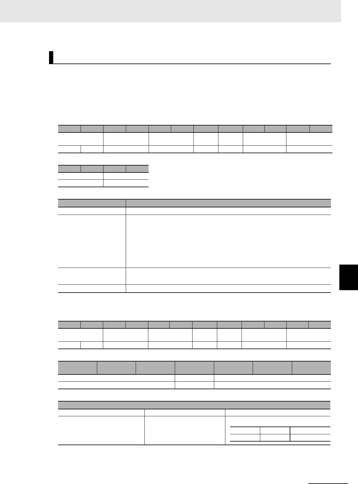
7 - 47
7 Modbus/TCP Communications
UHF RFID System V780-series Reader/Writer User’s Manual (Z389)
7-6 V780 Command Details
7
7-6-3 Modbus Expansion Communications Commands
Function
This command reads data from multiple RF Tags in the communications field.
You can get data from more than one RF Tag with one EXTENDED MULTIACCESS DATA READ
command.
Command Format
Response Formats
• Normal Response
EXTENDED MULTIACCESS DATA READ
Byte-0 Byte-1 Byte-2 Byte-3 Byte-4 Byte-5 Byte-6 Byte-7 Byte-8 Byte-9 Byte-10 Byte-11
Transaction identi-
fier
Protocol identifier Field length Unit
identifier
Function
code
Subfunction code Read area start
address
X X 0000 hex 000A hex FF hex 64 hex 0004 hex 2 bytes
Byte-12 Byte-13 Byte-14 Byte-15
Read size Options
2 bytes 2 bytes
Parameter Description
Subfunction code 0004 hex: EXTENDED MULTIACCESS DATA READ
Read area start address Specify in 4-digit hexadecimal the start address for reading data.
Setting ranges (word address specifications)
0000 to 07FF hex: Reserved area
1000 to 17FF hex: EPC area
2000 to 27FF hex: TID area
3000 to 37FF hex: User area
Read size Specify in 4-digit hexadecimal the start address for reading data.
Setting range: 0001 to 0020 hex (1 to 32)
Options For details, refer to 7-3 RF Communications Command Options on page 7-9.
Byte-0 Byte-1 Byte-2 Byte-3 Byte-4 Byte-5 Byte-6 Byte-7 Byte-8 Byte-9 Byte-10 Byte-11
Transaction identi-
fier
Protocol identifier Field length Unit
identifier
Function
code
Subfunction code Number of RF
Ta g s ( m)
X X 0000 hex 2 bytes FF hex 64 hex 0004 hex 0000 to 0040 hex
Byte-12 ... Byte-12 + n - 1 ... Byte-12+n*
(m-1) ... Byte-12+
(n*m)-1
Information from RF Tag 1 ... Information from RF Tag m
n = 4 to 132 bytes ... n = 4 to 132 bytes
Information from RF Tag x
Error code Read data Options
2 bytes 2 to 64 bytes 0 to 66 bytes
StoredPC EPC code Reception level
2 bytes 62 bytes 2 bytes
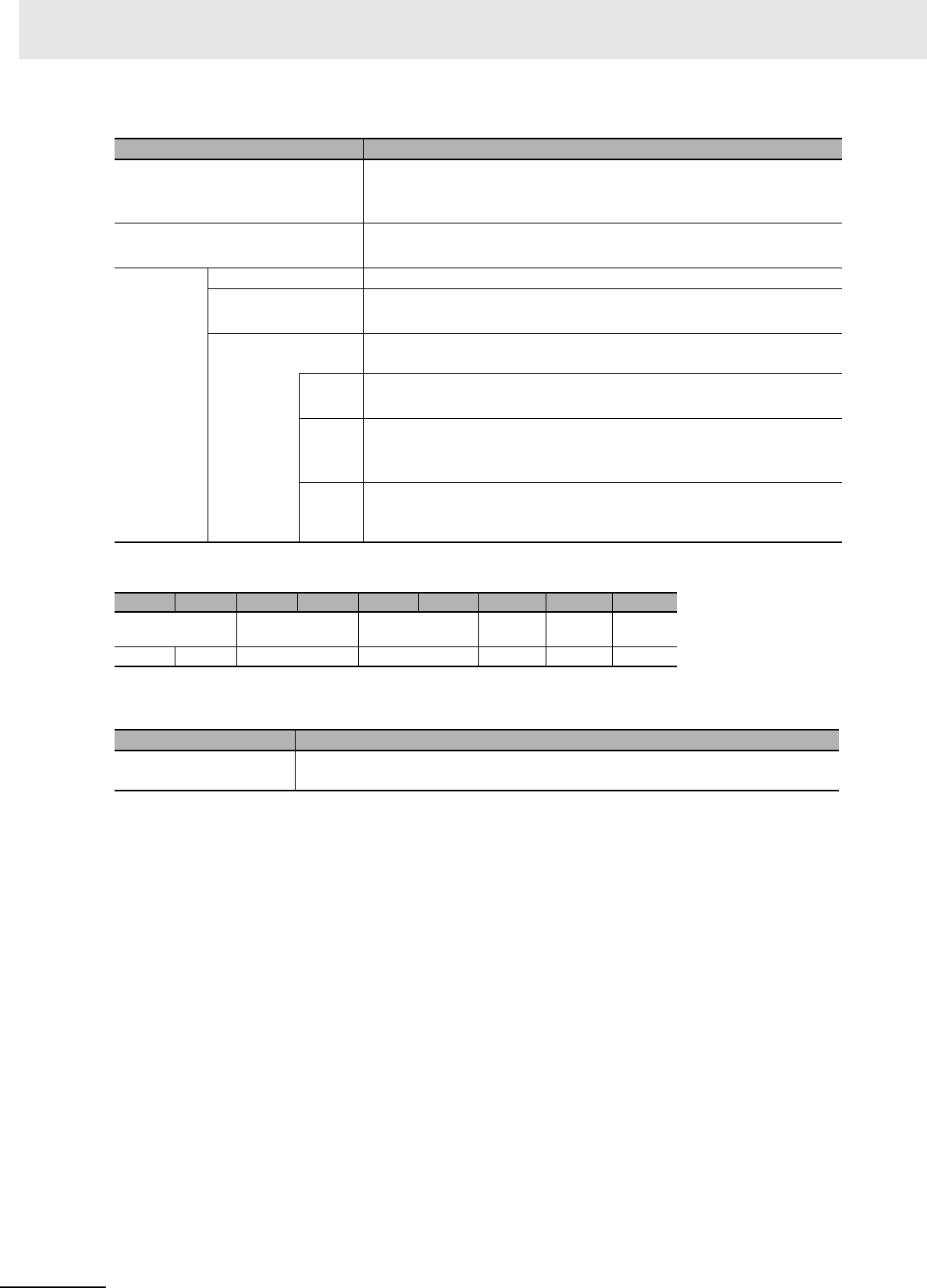
7 Modbus/TCP Communications
7 - 48 UHF RFID System V780-series Reader/Writer User’s Manual (Z389)
• Error Response
Note If the exception code is 04 hex (failure in slave device), this format is not used and a response is returned.
Execution Examples
Reading 4 Words of Data Starting from Word Address 0123 Hex (User Area) in Multiple RF Tags
with No Options
Example 1: Execution When Four RF Tags Are in the Communications Field
TX: 00000000000AFF640004312300040000
RX: 00000000002EFF6400040004
0000AAAAAAAAAAAAAAAA: RF Tag A error code + Read data (4 words, all AAAA
hex)
0000BBBBBBBBBBBBBBBB: RF Tag B error code + Read data (4 words, all BBBB
hex)
0000CCCCCCCCCCCCCCCC: RF Tag C error code + Read data (4 words, all CCCC
hex)
2002000000000000000000: RF Tag D error code (2002 hex (communications error))
Example 2: Execution When an RF Tag Is Not in the Communications Field (Exception Code: 04
Hex (Failure in Device))
TX: 00000000000AFF640004312300040000
RX: 000000000003FFE404
Parameter Description
Field length 000A to 2106 hex + (Option size × m)
• For details on option sizes, refer to 7-3 RF Communications Command
Options on page 7-9.
Number of RF Tags Gives the number of RF Tags that were detected in 4-digit decimal.
0000 to 0040 hex (0 to 64)
Information
from RF Tag
1
Error code For details, refer to ?9-2-1 ?????? (P.9-3)?.
Read data The data that was read from the RF Tag is attached.
The bytes that exceed the word count will be filled with 00 hex.
Options This section may be omitted depending on the option value for the SET
MULTIACCESS ID READ command.
Stored
PC
Gives the StoredPC data in 4-digit hexadecimal.
The upper 5 bits are the EPC word length.
EPC
code
Gives the Tag-specific information according to Gen2 standards.
All bytes of the EPC code section that exceed the EPC word length in the
StoredPC are filled with 00 hex.
Recep-
tion
level
The reception level is attached in signed 4-digit hexadecimal.
FFFF to FF9D hex (-1 to -99 [dBm])
Byte-0 Byte-1 Byte-2 Byte-3 Byte-4 Byte-5 Byte-6 Byte-7 Byte-8
Transaction identi-
fier
Protocol identifier Field length Unit
identifier
Function
code
Excep-
tion code
X X 0000 hex 0003 hex FF hex E4 hex 1 byte
Parameter Description
Exception code For details, refer to Exception Code on page 7-7 under 7-2-3 Response Format for
Error Completion on page 7-7.
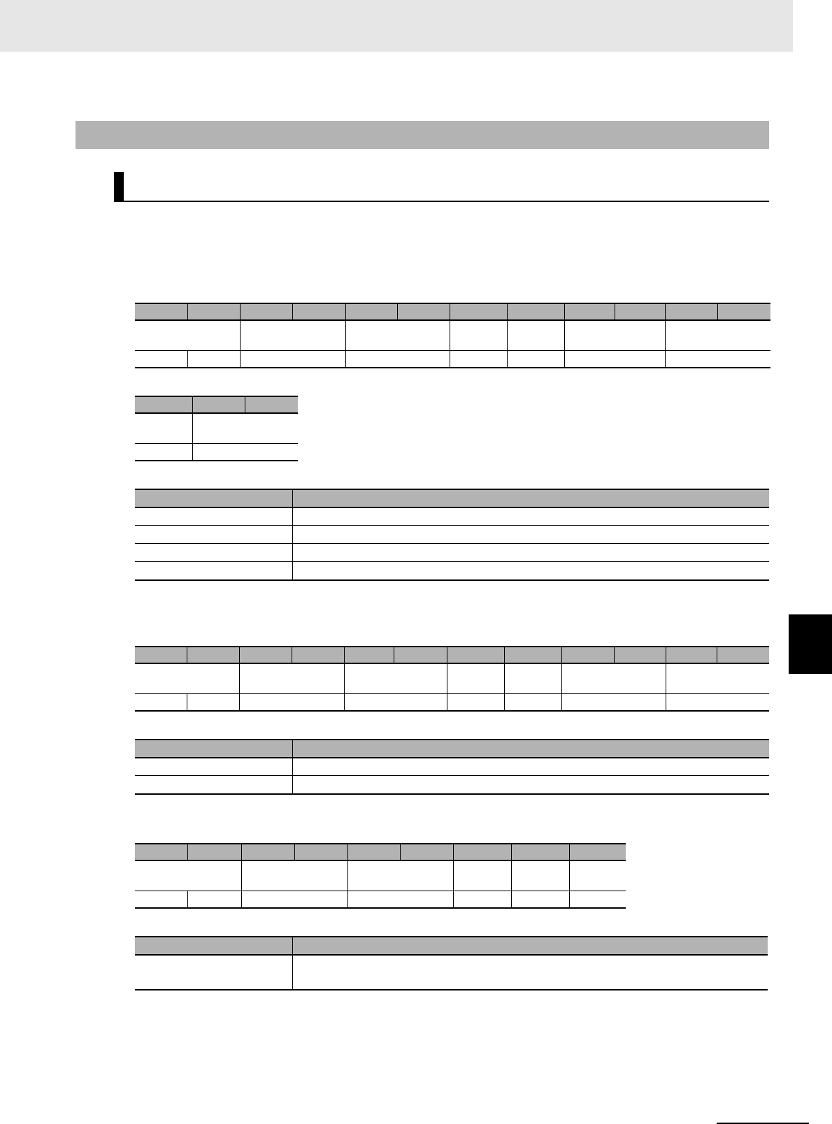
7 - 49
7 Modbus/TCP Communications
UHF RFID System V780-series Reader/Writer User’s Manual (Z389)
7-6 V780 Command Details
7
7-6-4 Reader/Writer Control Commands
Function
This command initializes the Reader/Writer settings. (That is, it returns them to the default settings.)
Command Format
Response Formats
• Normal Response
• Error Response
7-6-4 Reader/Writer Control Commands
INITIALIZE
Byte-0 Byte-1 Byte-2 Byte-3 Byte-4 Byte-5 Byte-6 Byte-7 Byte-8 Byte-9 Byte-10 Byte-11
Transaction identi-
fier
Protocol identifier Field length Unit
identifier
Function
code
Register address Word count
X X 0000 hex 0009 hex FF hex 10 hex A000 hex 0001 hex
Byte-12 Byte-13 Byte-14
Byte
count
Options
02 hex 0000 hex
Parameter Description
Register address The register address (A000 hex) that specifies initializing settings
Word count The number of words for the option (0001 hex)
Byte count The number of option bytes (02 hex)
Options 0000 hex: No options
Byte-0 Byte-1 Byte-2 Byte-3 Byte-4 Byte-5 Byte-6 Byte-7 Byte-8 Byte-9 Byte-10 Byte-11
Transaction identi-
fier
Protocol identifier Field length Unit
identifier
Function
code
Register address Word count
X X 0000 hex 0006 hex FF hex 10 hex A000 hex 0001 hex
Parameter Description
Register address The register address from the command is set.
Word count The word count from the command is set.
Byte-0 Byte-1 Byte-2 Byte-3 Byte-4 Byte-5 Byte-6 Byte-7 Byte-8
Transaction identi-
fier
Protocol identifier Field length Unit
identifier
Function
code
Excep-
tion code
X X 0000 hex 0003 hex FF hex 90 hex 1 byte
Parameter Description
Exception code For details, refer to Exception Code on page 7-7 under 7-2-3 Response Format for
Error Completion on page 7-7.

7 Modbus/TCP Communications
7 - 50 UHF RFID System V780-series Reader/Writer User’s Manual (Z389)
Execution Examples
Execution to Initialize the Reader/Writer Settings
TX: 000000000009FF10A0000001020000
RX: 000000000006FF10A0000001
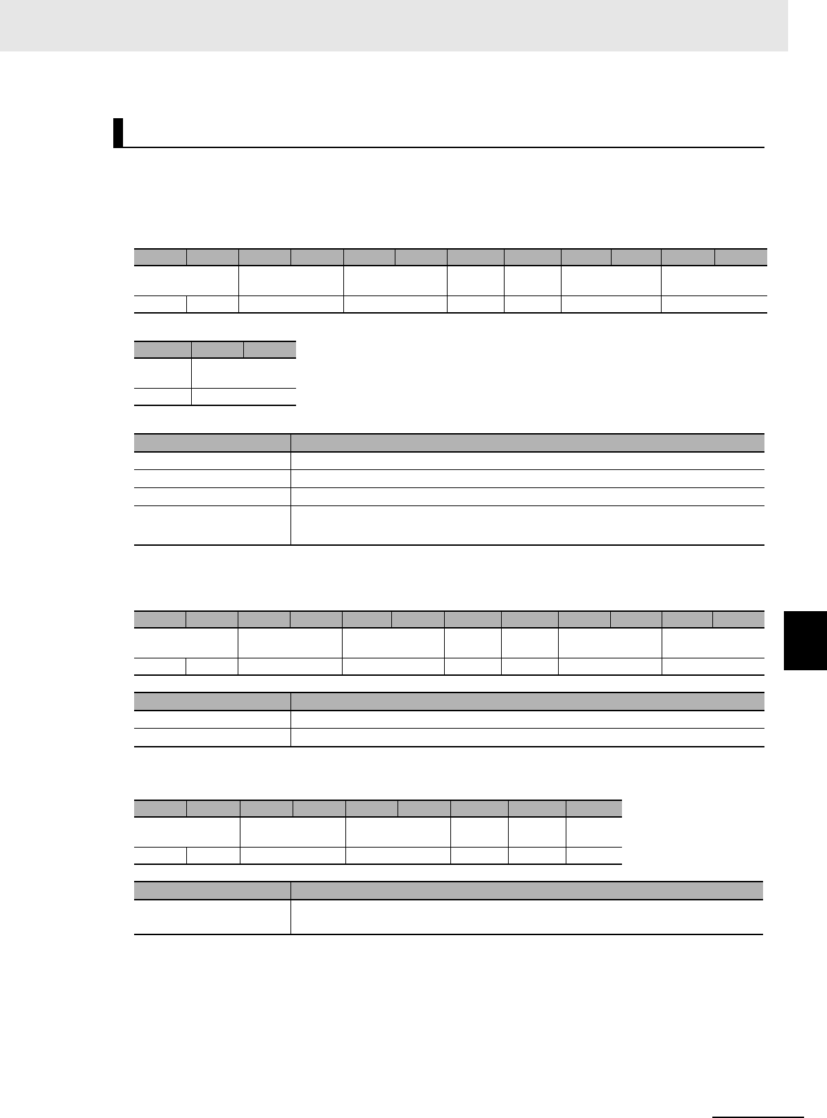
7 - 51
7 Modbus/TCP Communications
UHF RFID System V780-series Reader/Writer User’s Manual (Z389)
7-6 V780 Command Details
7
7-6-4 Reader/Writer Control Commands
Function
This command restarts the entire Reader/Writer.
Command Format
Response Formats
• Normal Response
Note A response is not returned for forced resetting.
• Error Response
Execution Examples
Execution to Restart the Entire Reader/Writer
TX: 000000000009FF10A1000001020000
RX: 000000000006FF10A1000001
RESET
Byte-0 Byte-1 Byte-2 Byte-3 Byte-4 Byte-5 Byte-6 Byte-7 Byte-8 Byte-9 Byte-10 Byte-11
Transaction identi-
fier
Protocol identifier Field length Unit
identifier
Function
code
Register address Word count
X X 0000 hex 0009 hex FF hex 10 hex A100 hex 0001 hex
Byte-12 Byte-13 Byte-14
Byte
count
Options
02 hex 2 bytes
Parameter Description
Register address The register address (A100 hex) that specifies resetting the Reader/Writer.
Word count The number of words for the option (0001 hex)
Byte count The number of option bytes (02 hex)
Options 0001 hex: Repeat
FFFF hex: Forced reset
Byte-0 Byte-1 Byte-2 Byte-3 Byte-4 Byte-5 Byte-6 Byte-7 Byte-8 Byte-9 Byte-10 Byte-11
Transaction identi-
fier
Protocol identifier Field length Unit
identifier
Function
code
Register address Word count
X X 0000 hex 0006 hex FF hex 10 hex A100 hex 0001 hex
Parameter Description
Register address The register address from the command is set.
Word count The word count from the command is set.
Byte-0 Byte-1 Byte-2 Byte-3 Byte-4 Byte-5 Byte-6 Byte-7 Byte-8
Transaction identi-
fier
Protocol identifier Field length Unit
identifier
Function
code
Excep-
tion code
X X 0000 hex 0003 hex FF hex 90 hex 1 byte
Parameter Description
Exception code For details, refer to Exception Code on page 7-7 under 7-2-3 Response Format for
Error Completion on page 7-7.
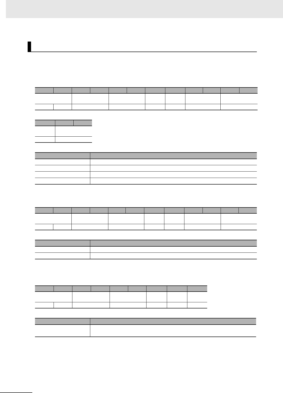
7 Modbus/TCP Communications
7 - 52 UHF RFID System V780-series Reader/Writer User’s Manual (Z389)
Function
This command stops RF Tag communications command execution by the Reader/Writer.
Command Format
Response Formats
• Normal Response
Note A response is not returned for forced resetting.
• Error Response
Execution Examples
Execution to Stop RF Tag Communications Command Execution by the Reader/Writer
TX: 000000000009FF10A2000001020000
RX: 000000000006FF10A2000001
STOP
Byte-0 Byte-1 Byte-2 Byte-3 Byte-4 Byte-5 Byte-6 Byte-7 Byte-8 Byte-9 Byte-10 Byte-11
Transaction identi-
fier
Protocol identifier Field length Unit
identifier
Function
code
Register address Word count
X X 0000 hex 0009 hex FF hex 10 hex A200 hex 0001 hex
Byte-12 Byte-13 Byte-14
Byte
count
Options
02 hex 0000 hex
Parameter Description
Register address The register address (A200 hex) that specifies stopping execution
Word count The number of words for the option (0001 hex)
Byte count The number of option bytes (02 hex)
Options 0000 hex: No options
Byte-0 Byte-1 Byte-2 Byte-3 Byte-4 Byte-5 Byte-6 Byte-7 Byte-8 Byte-9 Byte-10 Byte-11
Transaction identi-
fier
Protocol identifier Field length Unit
identifier
Function
code
Register address Word count
X X 0000 hex 0006 hex FF hex 10 hex A200 hex 0001 hex
Parameter Description
Register address The register address from the command is set.
Word count The word count from the command is set.
Byte-0 Byte-1 Byte-2 Byte-3 Byte-4 Byte-5 Byte-6 Byte-7 Byte-8
Transaction identi-
fier
Protocol identifier Field length Unit
identifier
Function
code
Excep-
tion code
X X 0000 hex 0003 hex FF hex 90 hex 1 byte
Parameter Description
Exception code For details, refer to Exception Code on page 7-7 under 7-2-3 Response Format for
Error Completion on page 7-7.
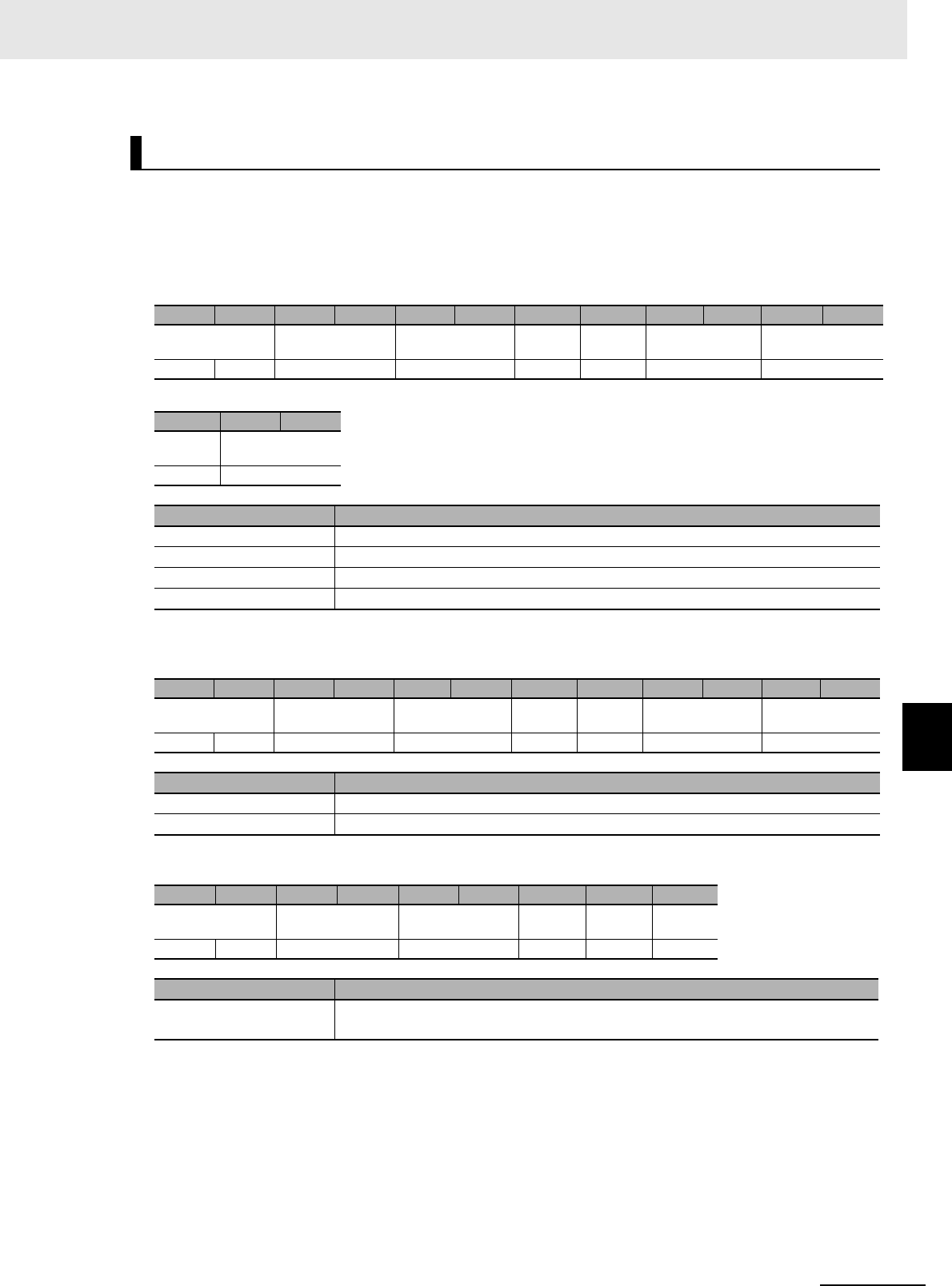
7 - 53
7 Modbus/TCP Communications
UHF RFID System V780-series Reader/Writer User’s Manual (Z389)
7-6 V780 Command Details
7
7-6-4 Reader/Writer Control Commands
Function
This command initializes the target level information of all the RF Tags that are being monitored by
the Reader/Writer in Focus Mode.
Command Format
Response Formats
• Normal Response
• Error Response
Execution Examples
Execution to Initialize Target Levels of All RF Tags Monitored by Reader/Writer in Focus Mode
TX: 000000000009FF10A3000001020000
RX: 000000000009FF10A3000001020000
RESET FOCUS
Byte-0 Byte-1 Byte-2 Byte-3 Byte-4 Byte-5 Byte-6 Byte-7 Byte-8 Byte-9 Byte-10 Byte-11
Transaction identi-
fier
Protocol identifier Field length Unit
identifier
Function
code
Register address Word count
X X 0000 hex 0009 hex FF hex 10 hex A300 hex 0001 hex
Byte-12 Byte-13 Byte-14
Byte
count
Options
02 hex 0000 hex
Parameter Description
Register address The register address (A300 hex) that specifies resetting the focus
Word count The number of words for the option (0001 hex)
Byte count The number of option bytes (02 hex)
Options 0000 hex: No options
Byte-0 Byte-1 Byte-2 Byte-3 Byte-4 Byte-5 Byte-6 Byte-7 Byte-8 Byte-9 Byte-10 Byte-11
Transaction identi-
fier
Protocol identifier Field length Unit
identifier
Function
code
Register address Word count
X X 0000 hex 0006 hex FF hex 10 hex A300 hex 0001 hex
Parameter Description
Register address The register address from the command is set.
Word count The word count from the command is set.
Byte-0 Byte-1 Byte-2 Byte-3 Byte-4 Byte-5 Byte-6 Byte-7 Byte-8
Transaction identi-
fier
Protocol identifier Field length Unit
identifier
Function
code
Excep-
tion code
X X 0000 hex 0003 hex FF hex 90 hex 1 byte
Parameter Description
Exception code For details, refer to Exception Code on page 7-7 under 7-2-3 Response Format for
Error Completion on page 7-7.
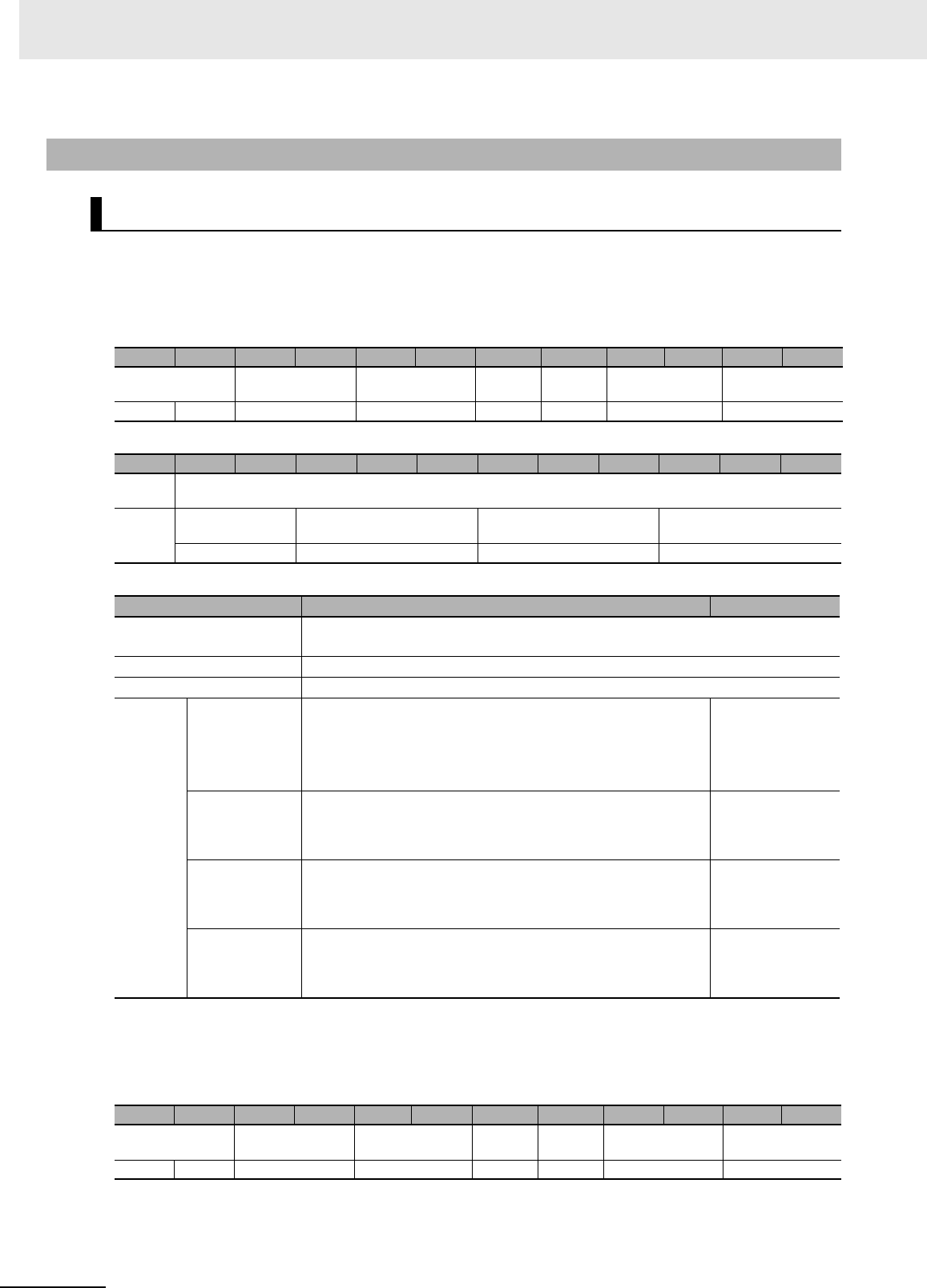
7 Modbus/TCP Communications
7 - 54 UHF RFID System V780-series Reader/Writer User’s Manual (Z389)
Function
This command sets the TCP/IP communications conditions of the Reader/Writer.
Command Format
Response Formats
• Normal Response
7-6-5 Reader/Writer Setting Commands: Network Settings
SET TCP/IP COMMUNICATIONS CONDITIONS
Byte-0 Byte-1 Byte-2 Byte-3 Byte-4 Byte-5 Byte-6 Byte-7 Byte-8 Byte-9 Byte-10 Byte-11
Transaction identi-
fier
Protocol identifier Field length Unit
identifier
Function
code
Register address Word count
X X 0000 hex 0015 hex FF hex 10 hex B000 hex 0007 hex
Byte-12 Byte-13 Byte-14 Byte-15 ... Byte-18 Byte-19 ... Byte-22 Byte-23 ... Byte-26
Byte
count
TCP/IP communications conditions
0E hex IP address setting
method
IP address Subnet mask Gateway address
2 bytes 4 bytes 4 bytes 4 bytes
Parameter Description Default setting
Register address The register address (B000 hex) that specifies the TCP/IP communications condi-
tions.
Word count The number of words in the TCP/IP communications conditions (0007 hex)
Byte count The number of bytes in the TCP/IP communications conditions (0E hex)
TCP/IP
commu-
nica-
tions
condi-
tions
IP address set-
ting method
Specify in 4-digit hexadecimal the IP address setting method.
0000 hex: Fixed setting
00001 hex: Obtain from BOOTP server
0002 hex: Get from BOOTP server as fixed settings
0000 hex
IP address*1
*1. Specify 00000000 hex for any IP address setting method other than using a fixed IP address.
Specify in 8-digit hexadecimal the fixed IP addresses to set.
Setting range: 00000000 to DFFFFFFF hex
Example: C0A801C8 hex (192.168.1.200)
C0A801C8 hex
Subnet mask*1 Specify in 8-digit hexadecimal the subnet mask to set.
Setting range: FF000000 to FFFFFFFF hex
Example: FFFFFF00 hex (255.255.255.0)
FFFFFF00 hex
Gateway
address*1
Specify in 8-digit hexadecimal the gateway address to set.
Setting range: 00000000 to DFFFFFFF hex
Example: C0A801FE hex (192.168.1.254)
C0A801FE hex
Byte-0 Byte-1 Byte-2 Byte-3 Byte-4 Byte-5 Byte-6 Byte-7 Byte-8 Byte-9 Byte-10 Byte-11
Transaction identi-
fier
Protocol identifier Field length Unit
identifier
Function
code
Register address Word count
X X 0000 hex 0006 hex FF hex 10 hex B000 hex 0007 hex

7 - 55
7 Modbus/TCP Communications
UHF RFID System V780-series Reader/Writer User’s Manual (Z389)
7-6 V780 Command Details
7
7-6-5 Reader/Writer Setting Commands: Network Settings
• Error Response
Execution Examples
Execution to Set the Following TCP/IP Communications Conditions in the Reader/Writer
IP address setting method: Fixed, IP address: 192.168.1.200, Subnet mask: 255.255.255.0, Gate-
way address: 192.168.1.1
TX: 000000000015FF10B00000070E0000C0A801C8FFFFFF00C0A80101
RX: 000000000006FF10B0000007
Parameter Description
Register address The register address from the command is set.
Word count The word count from the command is set.
Byte-0 Byte-1 Byte-2 Byte-3 Byte-4 Byte-5 Byte-6 Byte-7 Byte-8
Transaction identi-
fier
Protocol identifier Field length Unit
identifier
Function
code
Excep-
tion code
X X 0000 hex 0003 hex FF hex 90 hex 1 byte
Parameter Description
Exception code For details, refer to Exception Code on page 7-7 under 7-2-3 Response Format for
Error Completion on page 7-7.
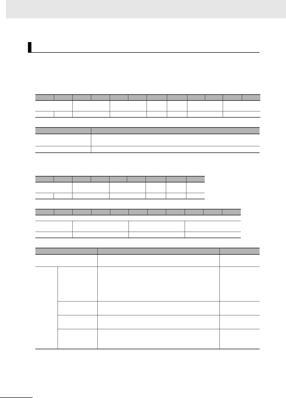
7 Modbus/TCP Communications
7 - 56 UHF RFID System V780-series Reader/Writer User’s Manual (Z389)
Function
This command is used to check the TCP/IP communications conditions that are set in the
Reader/Writer.
Command Format
Response Formats
• Normal Response
*1. For any IP address setting method except for using a fixed address, 00000000 hex is returned.
GET TCP/IP COMMUNICATIONS CONDITIONS
Byte-0 Byte-1 Byte-2 Byte-3 Byte-4 Byte-5 Byte-6 Byte-7 Byte-8 Byte-9 Byte-10 Byte-11
Transaction identi-
fier
Protocol identifier Field length Unit
identifier
Function
code
Register address Word count
X X 0000 hex 0006 hex FF hex 03 hex B000 hex 0007 hex
Parameter Description
Register address The register address (B000 hex) that specifies the TCP/IP communications condi-
tions.
Word count The number of words of the TCP/IP communications conditions to read (0007 hex)
Byte-0 Byte-1 Byte-2 Byte-3 Byte-4 Byte-5 Byte-6 Byte-7 Byte-8
Transaction identi-
fier
Protocol identifier Field length Unit
identifier
Function
code
Byte
count
X X 0000 hex 0011 hex FF hex 03 hex 0E hex
Byte-9 Byte-10 Byte-11 ... Byte-14 Byte-15 ... Byte-18 Byte-19 ... Byte-22
TCP/IP communications conditions
IP address setting
method
IP address Subnet mask Gateway address
2 bytes 4 bytes 4 bytes 4 bytes
Parameter Description Default setting
Byte count The number of bytes in the TCP/IP communications condi-
tions that were read (0E hex)
TCP/IP
commu-
nica-
tions
condi-
tions
IP address set-
ting method
Gives the IP address setting method that was read in 4-digit
hexadecimal.
0000 hex: Fixed setting
00001 hex: Obtain from BOOTP server
0002 hex: Get from BOOTP server as fixed settings
0000 hex
IP address*1 Gives the IP address that was read in 8-digit hexadecimal.
Example: C0A801C8 hex (192.168.1.200)
C0A801C8 hex
Subnet mask*1 Gives the subnet mask that was read in 8-digit hexadecimal.
Example: FFFFFF00 hex (255.255.255.0)
FFFFFF00 hex
Gateway
address*1
Gives the gateway address that was read in 8-digits hexa-
decimal.
Example: C0A801FE hex (192.168.1.254)
C0A801FE hex

7 - 57
7 Modbus/TCP Communications
UHF RFID System V780-series Reader/Writer User’s Manual (Z389)
7-6 V780 Command Details
7
7-6-5 Reader/Writer Setting Commands: Network Settings
• Error Response
Execution Examples
Execution When the Following TCP/IP Communications Conditions Are Set in the Reader/Writer
IP address setting method: Fixed, IP address: 192.168.1.200, Subnet mask: 255.255.255.0, Gate-
way address: 192.168.1.1
TX: 000000000006FF03B0000007
RX: 000000000011FF030E0000C0A801C8FFFFFF00C0A80101
Byte-0 Byte-1 Byte-2 Byte-3 Byte-4 Byte-5 Byte-6 Byte-7 Byte-8
Transaction identi-
fier
Protocol identifier Field length Unit iden-
tifier
Function
code
Excep-
tion code
X X 0000 hex 0003 hex FF hex 83 hex 1 byte
Parameter Description
Exception code For details, refer to Exception Code on page 7-7 under 7-2-3 Response Format for
Error Completion on page 7-7.
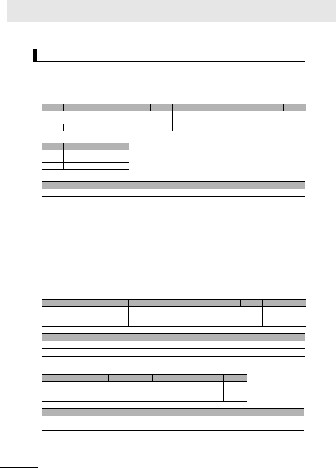
7 Modbus/TCP Communications
7 - 58 UHF RFID System V780-series Reader/Writer User’s Manual (Z389)
Function
This command is used to set or clear a name for the Reader/Writer.
Command Format
Response Formats
• Normal Response
• Error Response
SET DEVICE NAME
Byte-0 Byte-1 Byte-2 Byte-3 Byte-4 Byte-5 Byte-6 Byte-7 Byte-8 Byte-9 Byte-10 Byte-11
Transaction identi-
fier
Protocol identifier Field length Unit
identifier
Function
code
Register address Word count
X X 0000 hex 0047 hex FF hex 10 hex B100 hex 0020 hex
Byte-12 Byte-13 ... Byte-76
Byte
count
Device name
40 hex 64 bytes
Parameter Description
Register address The register address (B100 hex) that specifies the device name
Word count The number of words in the device name (0020 hex)
Byte count The number of bytes in the device name (40 hex)
Device name ASCII characters, 64 bytes max.
(63 ASCII characters max. + End code of 00 hex)
If there are fewer than 63 characters, the remaining bytes are filled with 00 hex.
The device name is given with ASCII characters 20 hex (space) to 7E hex (~).
Specify 00 hex for all bytes to clear the device name.
Byte-0 Byte-1 Byte-2 Byte-3 Byte-4 Byte-5 Byte-6 Byte-7 Byte-8 Byte-9 Byte-10 Byte-11
Transaction identi-
fier
Protocol identifier Field length Unit
identifier
Function
code
Register address Word count
X X 0000 hex 0006 hex FF hex 10 hex B100 hex 0020 hex
Parameter Description
Register address The register address from the command is set.
Word count The word count from the command is set.
Byte-0 Byte-1 Byte-2 Byte-3 Byte-4 Byte-5 Byte-6 Byte-7 Byte-8
Transaction identi-
fier
Protocol identifier Field length Unit iden-
tifier
Function
code
Excep-
tion code
X X 0000 hex 0003 hex FF hex 90 hex 1 byte
Parameter Description
Exception code For details, refer to Exception Code on page 7-7 under Response Format for Error
Completion on page 7-7.

7 - 59
7 Modbus/TCP Communications
UHF RFID System V780-series Reader/Writer User’s Manual (Z389)
7-6 V780 Command Details
7
7-6-5 Reader/Writer Setting Commands: Network Settings
Execution Examples
Execution to Set the Reader/Writer Device Name to V780-A001
TX: 000000000047FF10B10000204056363830532D413030310000000000…00
RX: 000000000006FF10B1000020
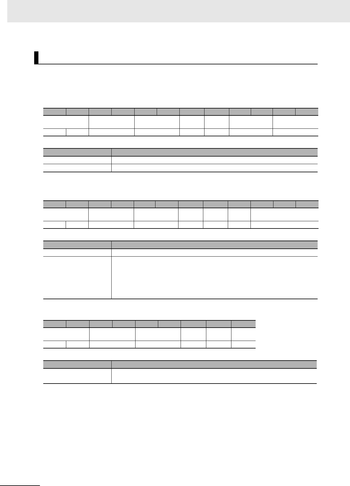
7 Modbus/TCP Communications
7 - 60 UHF RFID System V780-series Reader/Writer User’s Manual (Z389)
Function
This command is used to check the name that is set in the Reader/Writer.
Command Format
Response Formats
• Normal Response
• Error Response
Execution Examples
Execution When the Reader/Writer Device Name Is Set to V780-A001
TX: 000000000006FF03B1000020
RX: 000000000043FF034056363830532D413030310000000000…00
GET DEVICE NAME
Byte-0 Byte-1 Byte-2 Byte-3 Byte-4 Byte-5 Byte-6 Byte-7 Byte-8 Byte-9 Byte-10 Byte-11
Transaction identi-
fier
Protocol identifier Field length Unit
identifier
Function
code
Register address Word count
X X 0000 hex 0006 hex FF hex 03 hex B100 hex 0020 hex
Parameter Description
Register address The register address (B100 hex) that specifies the device name
Word count The number of words in the device name (0020 hex)
Byte-0 Byte-1 Byte-2 Byte-3 Byte-4 Byte-5 Byte-6 Byte-7 Byte-8 Byte-9 ... Byte-72
Transaction identi-
fier
Protocol identifier Field length Unit
identifier
Function
code
Byte
count
Device name
X X 0000 hex 0043 hex FF hex 03 hex 40 hex 64 bytes
Parameter Description
Byte count The number of words in the device name that was read (40 hex)
Device name The device name that was read is given with up to 64 bytes of ASCII characters (up
to 63 ASCII characters plus the end code (00 hex))
If there are fewer than 63 characters, the remaining bytes are filled with 00 hex.
The device name is given with ASCII characters 20 hex (space) to 7E hex (~).
Byte-0 Byte-1 Byte-2 Byte-3 Byte-4 Byte-5 Byte-6 Byte-7 Byte-8
Transaction identi-
fier
Protocol identifier Field length Unit
identifier
Function
code
Excep-
tion code
X X 0000 hex 0003 hex FF hex 83 hex 1 byte
Parameter Description
Exception code For details, refer to Exception Code on page 7-7 under 7-2-3 Response Format for
Error Completion on page 7-7.
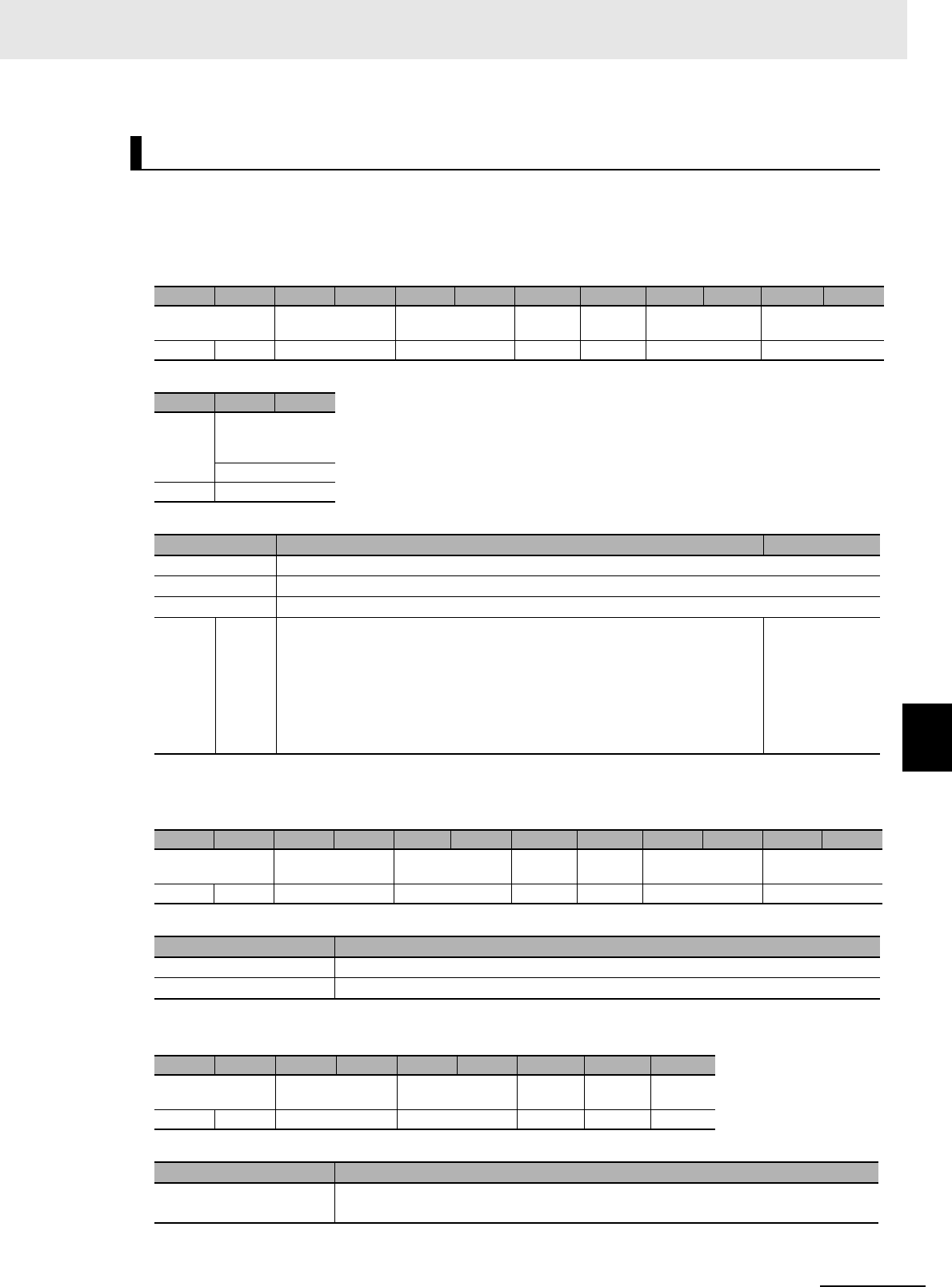
7 - 61
7 Modbus/TCP Communications
UHF RFID System V780-series Reader/Writer User’s Manual (Z389)
7-6 V780 Command Details
7
7-6-5 Reader/Writer Setting Commands: Network Settings
Function
This command sets the Modbus/TCP communications conditions of the Reader/Writer.
Command Format
Response Formats
• Normal Response
• Error Response
SET MODBUS/TCP COMMUNICATIONS CONDITIONS
Byte-0 Byte-1 Byte-2 Byte-3 Byte-4 Byte-5 Byte-6 Byte-7 Byte-8 Byte-9 Byte-10 Byte-11
Transaction identi-
fier
Protocol identifier Field length Unit
identifier
Function
code
Register address Word count
X X 0000 hex 0009 hex FF hex 10 hex B200 hex 0001 hex
Byte-12 Byte-13 Byte-14
Byte
count
Modbus/TC com-
munications condi-
tions
Port number
02 hex 2 bytes
Parameter Description Default setting
Register address The register address (B200 hex) that specifies the Modbus/TCP communications conditions
Word count The number of words in the Modbus/TCP communications conditions (0001 hex)
Byte count The number of bytes in the Modbus/TCP communications conditions (02 hex)
Mod-
bus/TC
com-
muni-
cations
condi-
tions
Port
num-
ber
Specify the Modbus/TCP communications port number in 4-digit hexadeci-
mal.
Setting range: 01F6 hex or 0400 to FFFF hex
Example: 01F6 hex (502)
• IANA manages ports 000 to 03FF hex.
01F6 hex (502)
Byte-0 Byte-1 Byte-2 Byte-3 Byte-4 Byte-5 Byte-6 Byte-7 Byte-8 Byte-9 Byte-10 Byte-11
Transaction identi-
fier
Protocol identifier Field length Unit
identifier
Function
code
Register address Word count
X X 0000 hex 0006 hex FF hex 10 hex B200 hex 0001 hex
Parameter Description
Register address The register address from the command is set.
Word count The word count from the command is set.
Byte-0 Byte-1 Byte-2 Byte-3 Byte-4 Byte-5 Byte-6 Byte-7 Byte-8
Transaction identi-
fier
Protocol identifier Field length Unit
identifier
Function
code
Excep-
tion code
X X 0000 hex 0003 hex FF hex 90 hex 1 byte
Parameter Description
Exception code For details, refer to Exception Code on page 7-7 under Response Format for Error
Completion on page 7-7.

7 Modbus/TCP Communications
7 - 62 UHF RFID System V780-series Reader/Writer User’s Manual (Z389)
Execution Examples
Execution to Set the Following Modbus/TCP Communications Conditions in the Reader/Writer
Port number: 502
TX: 000000000009FF10B20000010201F6
RX: 000000000006FF10B2000001
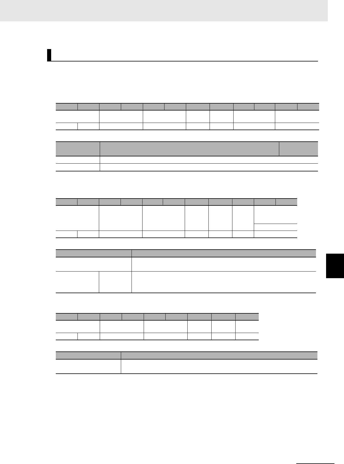
7 - 63
7 Modbus/TCP Communications
UHF RFID System V780-series Reader/Writer User’s Manual (Z389)
7-6 V780 Command Details
7
7-6-5 Reader/Writer Setting Commands: Network Settings
Function
This command is used to check the Modbus/TCP communications conditions of the Reader/Writer.
Command Format
Response Formats
• Normal Response
• Error Response
Execution Examples
Execution When the Following Modbus/TCP Communications Conditions Are Set in the
Reader/Writer
Port number: 502
TX: 000000000006FF03B2000001
RX: 000000000005FF030201F6
GET MODBUS/TCP COMMUNICATIONS CONDITIONS
Byte-0 Byte-1 Byte-2 Byte-3 Byte-4 Byte-5 Byte-6 Byte-7 Byte-8 Byte-9 Byte-10 Byte-11
Transaction identi-
fier
Protocol identifier Field length Unit
identifier
Function
code
Register address Word count
X X 0000 hex 0006 hex FF hex 03 hex B200 hex 0001 hex
Parameter Description Default set-
ting
Register address The register address (B200 hex) that specifies the Modbus/TCP communications conditions
Word count The number of words of the Modbus/TCP communications conditions to read (0001 hex)
Byte-0 Byte-1 Byte-2 Byte-3 Byte-4 Byte-5 Byte-6 Byte-7 Byte-8 Byte-9 Byte-10
Transaction identi-
fier
Protocol identifier Field length Unit
identifier
Function
code
Byte
count
Modbus/TC com-
munications condi-
tions
Port number
X X 0000 hex 0005 hex FF hex 03 hex 02 hex 2 bytes
Parameter Description
Byte count The number of bytes in the Modbus/TCP communications conditions that were
read (02 hex)
Modbus/TC
communica-
tions conditions
Port num-
ber
Gives the Modbus/TCP communications port number in 4-digit hexadecimal.
Example: 01F6 hex (502)
Byte-0 Byte-1 Byte-2 Byte-3 Byte-4 Byte-5 Byte-6 Byte-7 Byte-8
Transaction identi-
fier
Protocol identifier Field length Unit
identifier
Function
code
Excep-
tion code
X X 0000 hex 0003 hex FF hex 83 hex 1 byte
Parameter Description
Exception code For details, refer to Exception Code on page 7-7 under 7-2-3 Response Format for
Error Completion on page 7-7.
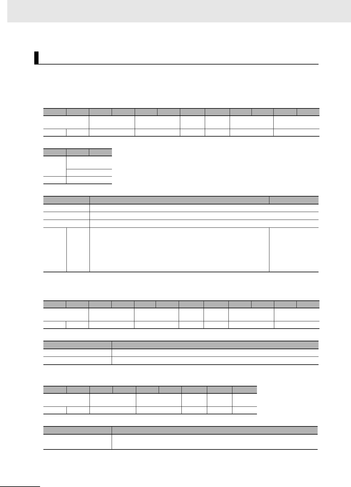
7 Modbus/TCP Communications
7 - 64 UHF RFID System V780-series Reader/Writer User’s Manual (Z389)
Function
This command sets the Web browser communications conditions of the Reader/Writer.
Command Format
Response Formats
• Normal Response
• Error Response
SET WEB COMMUNICATIONS CONDITIONS
Byte-0 Byte-1 Byte-2 Byte-3 Byte-4 Byte-5 Byte-6 Byte-7 Byte-8 Byte-9 Byte-10 Byte-11
Transaction identi-
fier
Protocol identifier Field length Unit
identifier
Function
code
Register address Word count
X X 0000 hex 0009 hex FF hex 10 hex B300 hex 0001 hex
Byte-12 Byte-13 Byte-14
Byte
count
Web communica-
tions conditions
Port number
02 hex 2 bytes
Parameter Description Default setting
Register address The register address (B300 hex) that specifies the Web communications conditions
Word count The number of words in the Web communications conditions (0001 hex)
Byte count The number of bytes in the Web communications conditions (02 hex)
Web
com-
muni-
cations
condi-
tions
Port
num-
ber
Specify the Web communications port number in 4-digit hexadecimal.
Setting range: 0400 to FFFF hex
Example: 1BB2 hex (7090)
• IANA manages ports 000 to 03FF hex.
1BB2 hex (7090)
Byte-0 Byte-1 Byte-2 Byte-3 Byte-4 Byte-5 Byte-6 Byte-7 Byte-8 Byte-9 Byte-10 Byte-11
Transaction identi-
fier
Protocol identifier Field length Unit
identifier
Function
code
Register address Word count
X X 0000 hex 0006 hex FF hex 10 hex B300 hex 0001 hex
Parameter Description
Register address The register address from the command is set.
Word count The word count from the command is set.
Byte-0 Byte-1 Byte-2 Byte-3 Byte-4 Byte-5 Byte-6 Byte-7 Byte-8
Transaction identi-
fier
Protocol identifier Field length Unit
identifier
Function
code
Excep-
tion code
X X 0000 hex 0003 hex FF hex 90 hex 1 byte
Parameter Description
Exception code For details, refer to Exception Code on page 7-7 under 7-2-3 Response Format for
Error Completion on page 7-7.

7 - 65
7 Modbus/TCP Communications
UHF RFID System V780-series Reader/Writer User’s Manual (Z389)
7-6 V780 Command Details
7
7-6-5 Reader/Writer Setting Commands: Network Settings
Execution Examples
Execution to Set the Following Web Communications Conditions in the Reader/Writer
Port number: 7090
TX: 000000000009FF10B3000001021BB2
RX: 000000000006FF10B3000001
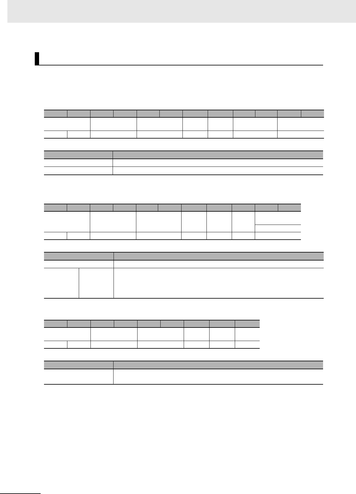
7 Modbus/TCP Communications
7 - 66 UHF RFID System V780-series Reader/Writer User’s Manual (Z389)
Function
This command is used to check the Web browser communications conditions of the Reader/Writer.
Command Format
Response Formats
• Normal Response
• Error Response
Execution Examples
Execution When the Following Web Communications Conditions Are Set in the Reader/Writer
Port number: 7090
TX: 000000000006FF03B3000001
RX: 000000000005FF03021BB2
GET WEB COMMUNICATIONS CONDITIONS
Byte-0 Byte-1 Byte-2 Byte-3 Byte-4 Byte-5 Byte-6 Byte-7 Byte-8 Byte-9 Byte-10 Byte-11
Transaction identi-
fier
Protocol identifier Field length Unit
identifier
Function
code
Register address Word count
X X 0000 hex 0006 hex FF hex 03 hex B300 hex 0001 hex
Parameter Description
Register address The register address (B300 hex) that specifies the Web communications conditions
Word count The number of words of the Web communications conditions to read (0001 hex)
Byte-0 Byte-1 Byte-2 Byte-3 Byte-4 Byte-5 Byte-6 Byte-7 Byte-8 Byte-9 Byte-10
Transaction identi-
fier
Protocol identifier Field length Unit
identifier
Function
code
Byte
count
Web communica-
tions conditions
Port number
X X 0000 hex 0005 hex FF hex 03 hex 02 hex 2 bytes
Parameter Description
Byte count The number of bytes in the Web communications conditions that were read (02 hex)
Web com-
munica-
tions
conditions
Port num-
ber
Gives the Web communications port number that was read in 4-digit hexadecimal.
Example: 1BB2 hex (7090)
Byte-0 Byte-1 Byte-2 Byte-3 Byte-4 Byte-5 Byte-6 Byte-7 Byte-8
Transaction identi-
fier
Protocol identifier Field length Unit
identifier
Function
code
Excep-
tion code
X X 0000 hex 0003 hex FF hex 83 hex 1 byte
Parameter Description
Exception code For details, refer to Exception Code on page 7-7 under 7-2-3 Response Format for
Error Completion on page 7-7.
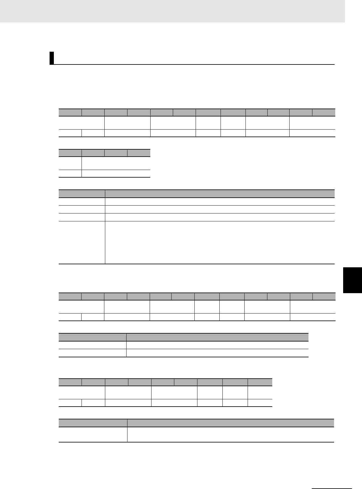
7 - 67
7 Modbus/TCP Communications
UHF RFID System V780-series Reader/Writer User’s Manual (Z389)
7-6 V780 Command Details
7
7-6-5 Reader/Writer Setting Commands: Network Settings
Function
This command sets or clears the Reader/Writer login password for the Web browser interface.
Command Format
Response Formats
• Normal Response
• Error Response
SET WEB PASSWORD
Byte-0 Byte-1 Byte-2 Byte-3 Byte-4 Byte-5 Byte-6 Byte-7 Byte-8 Byte-9 Byte-10 Byte-11
Transaction identi-
fier
Protocol identifier Field length Unit
identifier
Function
code
Register address Word count
X X 0000 hex 0017 hex FF hex 10 hex B400 hex 0008 hex
Byte-12 Byte-13 ... Byte-28
Byte
count
Web password
10 hex 16 bytes
Parameter Description
Register address The register address (B400 hex) that specifies the Web password
Word count The number of words in the Web password (0008 hex)
Byte count The number of bytes in the Web password (10 hex)
Web password Specify the Web password with up to 16 bytes of ASCII characters (up to 15 ASCII characters
plus the end code (00 hex)).
If there are fewer than 15 characters, fill the remaining bytes with 00 hex.
You can specify ASCII characters 20 hex (space) to 7E hex (~).
To clear the password, specify 00 hex for all of the write data.
Byte-0 Byte-1 Byte-2 Byte-3 Byte-4 Byte-5 Byte-6 Byte-7 Byte-8 Byte-9 Byte-10 Byte-11
Transaction identi-
fier
Protocol identifier Field length Unit
identifier
Function
code
Register address Word count
X X 0000 hex 0006 hex FF hex 10 hex B400 hex 0008 hex
Parameter Description
Register address The register address from the command is set.
Word count The word count from the command is set.
Byte-0 Byte-1 Byte-2 Byte-3 Byte-4 Byte-5 Byte-6 Byte-7 Byte-8
Transaction identi-
fier
Protocol identifier Field length Unit
identifier
Function
code
Excep-
tion code
X X 0000 hex 0003 hex FF hex 90 hex 1 byte
Parameter Description
Exception code For details, refer to Exception Code on page 7-7 under 7-2-3 Response Format for
Error Completion on page 7-7.

7 Modbus/TCP Communications
7 - 68 UHF RFID System V780-series Reader/Writer User’s Manual (Z389)
Execution Examples
Setting the Reader/Writer Web Password to “password”
TX: 000000000017FF10B40000081070617373776F72640000000000000000
RX: 000000000006FF10B4000008
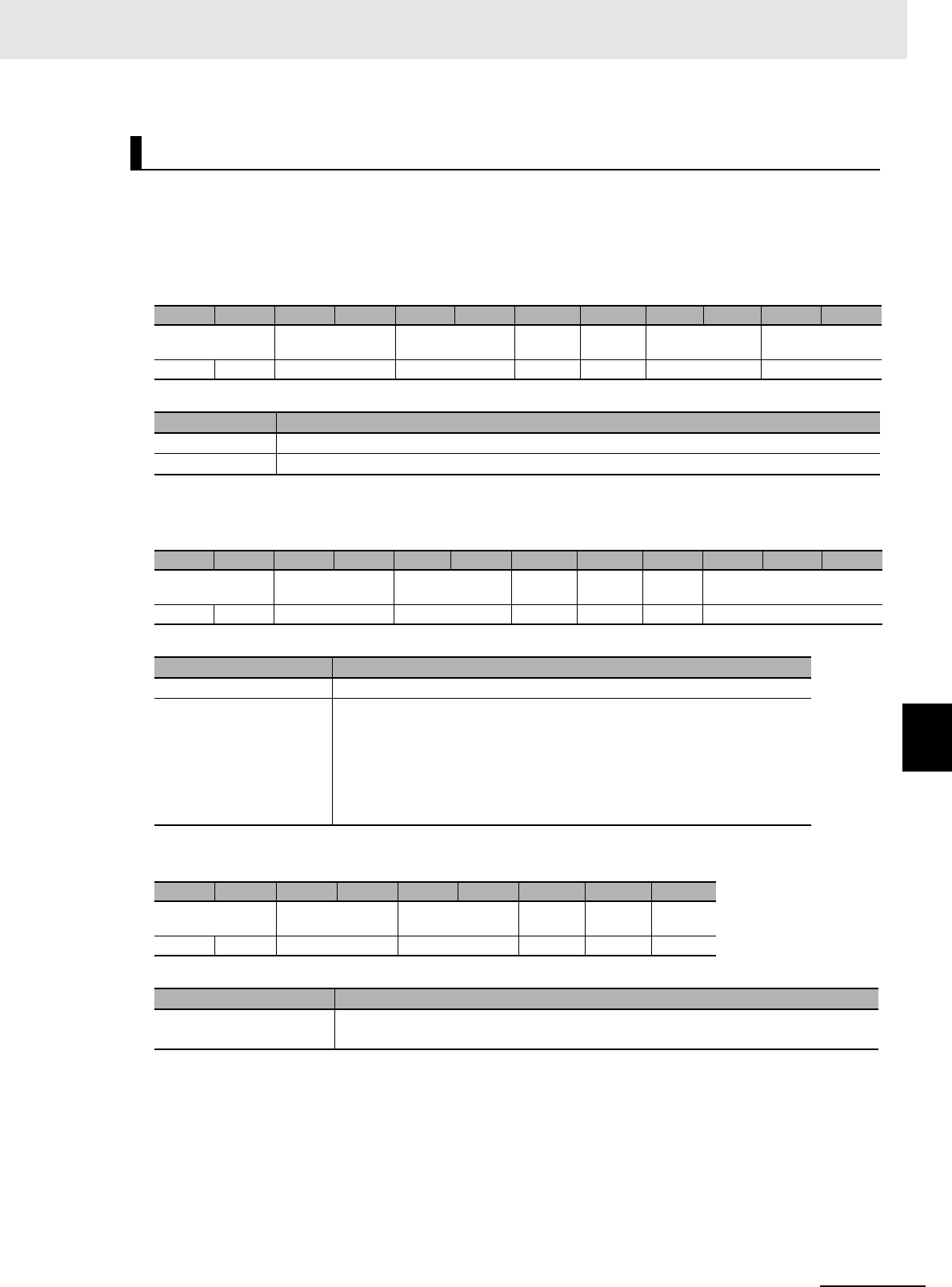
7 - 69
7 Modbus/TCP Communications
UHF RFID System V780-series Reader/Writer User’s Manual (Z389)
7-6 V780 Command Details
7
7-6-5 Reader/Writer Setting Commands: Network Settings
Function
This command is used to check the login password that is set in the Reader/Writer for the Web
browser interface.
Command Format
Response Formats
• Normal Response
• Error Response
Execution Examples
Execution When the Reader/Writer Web Password Is Set to “password”
TX: 000000000006FF03B4000008
RX: 000000000013FF031070617373776F72640000000000000000
GET WEB PASSWORD
Byte-0 Byte-1 Byte-2 Byte-3 Byte-4 Byte-5 Byte-6 Byte-7 Byte-8 Byte-9 Byte-10 Byte-11
Transaction identi-
fier
Protocol identifier Field length Unit
identifier
Function
code
Register address Word count
X X 0000 hex 0006 hex FF hex 03 hex B400 hex 0008 hex
Parameter Description
Register address The register address (B400 hex) that specifies the Web password
Word count The number of words in the Web password (0008 hex)
Byte-0 Byte-1 Byte-2 Byte-3 Byte-4 Byte-5 Byte-6 Byte-7 Byte-8 Byte-9 ... Byte-24
Transaction identi-
fier
Protocol identifier Field length Unit
identifier
Function
code
Byte
count
Web password
X X 0000 hex 0013 hex FF hex 03 hex 10 hex 16 bytes
Parameter Description
Byte count The number of bytes in the Web password that was read (10 hex)
Web password Gives the Web password that was read with up to 16 bytes of ASCII char-
acters (up to 15 ASCII characters plus the end code (00 hex)).
If there are fewer than 15 characters, the remaining bytes are filled with
00 hex.
The Web password is given with ASCII characters 20 hex (space) to 7E
hex (~).
Byte-0 Byte-1 Byte-2 Byte-3 Byte-4 Byte-5 Byte-6 Byte-7 Byte-8
Transaction identi-
fier
Protocol identifier Field length Unit
identifier
Function
code
Excep-
tion code
X X 0000 hex 0003 hex FF hex 83 hex 1 byte
Parameter Description
Exception code For details, refer to Exception Code on page 7-7 under 7-2-3 Response Format for
Error Completion on page 7-7.
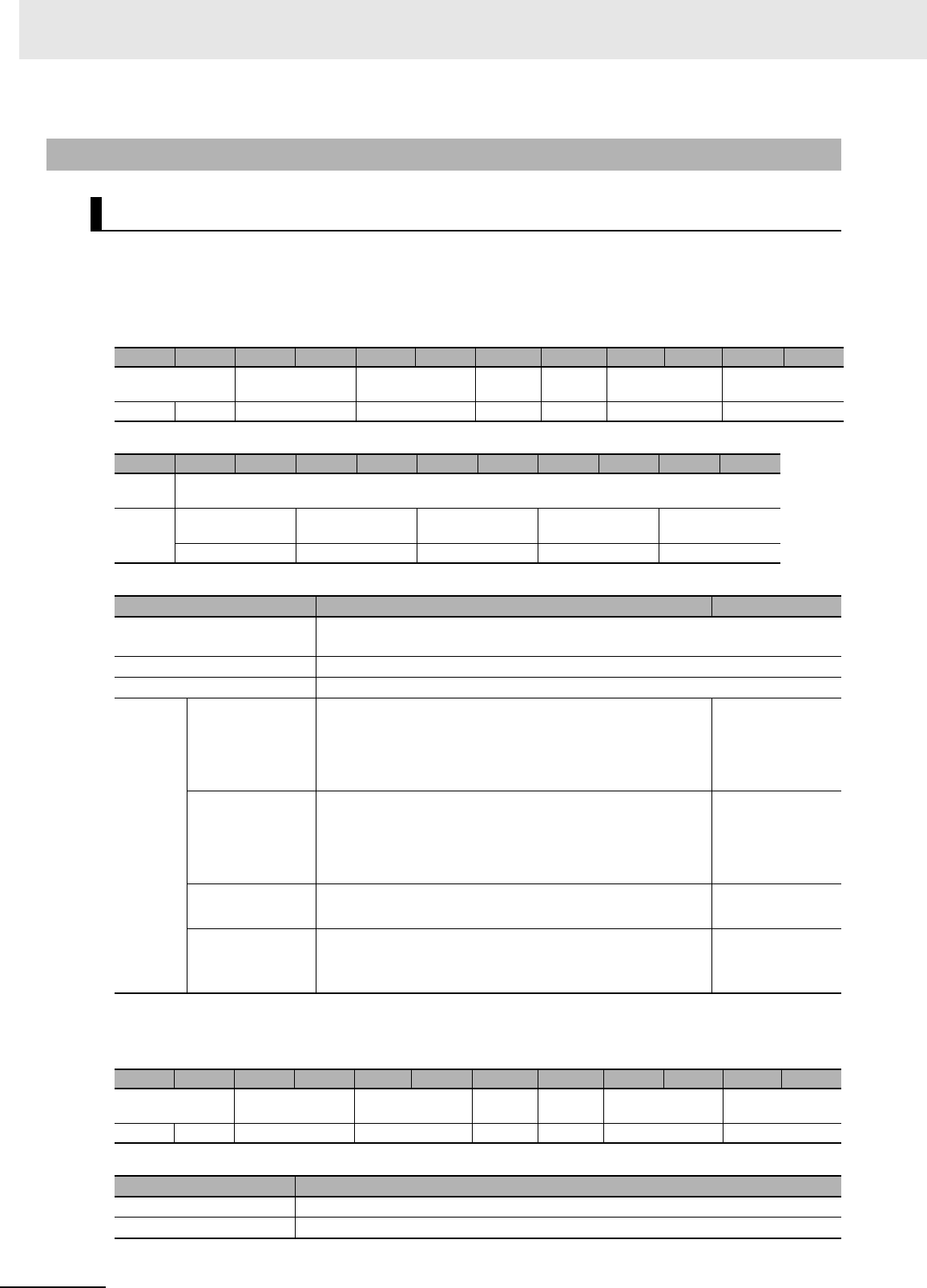
7 Modbus/TCP Communications
7 - 70 UHF RFID System V780-series Reader/Writer User’s Manual (Z389)
Function
This command sets the communications conditions for the Reader/Writer.
Command Format
Response Formats
• Normal Response
7-6-6 Reader/Writer Setting Commands: Communications Settings
SET TAG COMMUNICATIONS CONDITIONS
Byte-0 Byte-1 Byte-2 Byte-3 Byte-4 Byte-5 Byte-6 Byte-7 Byte-8 Byte-9 Byte-10 Byte-11
Transaction identi-
fier
Protocol identifier Field length Unit
identifier
Function
code
Register address Word count
X X 0000 hex 0011 hex FF hex 10 hex C000 hex 0005 hex
Byte-12 Byte-13 Byte-14 Byte-15 Byte-16 Byte-17 Byte-18 Byte-19 Byte-20 Byte-21 Byte-22
Byte
count
Communications conditions
0A hex RF communica-
tions mode
RF communica-
tions speed
RF communica-
tions timeout time
Write verification Reserved
2 bytes 2 bytes 2 bytes 2 bytes 0000 hex
Parameter Description Default setting
Register address The register address (C000 hex) that specifies the RF communications condi-
tions
Word count The number of words in the RF communications conditions (0005 hex)
Byte count The number of bytes in the RF communications conditions (0A hex)
Commu-
nica-
tions
condi-
tions
RF communica-
tions mode
Specify the communications mode in 4-digit hexadecimal.
0000 hex: Once
0001 hex: Auto
0002 hex: Focus
0000 hex
RF communica-
tions speed
Specify the communications speed in 4-digit hexadecimal.
0000 hex: Automatic (default)
0001 hex: High speed
0002 hex: Normal speed
0000 hex
RF communica-
tions timeout time
Specify the RF communications timeout time.
0001 to EA60 hex (1 to 60,000 [ms])
00FA hex
(250)
Write verification Specify in 4-digit hexadecimal whether to perform write veri-
fication.
0000 hex: Disable, 0001 hex: Enable
0001 hex
Byte-0 Byte-1 Byte-2 Byte-3 Byte-4 Byte-5 Byte-6 Byte-7 Byte-8 Byte-9 Byte-10 Byte-11
Transaction identi-
fier
Protocol identifier Field length Unit
identifier
Function
code
Register address Word count
X X 0000 hex 0006 hex FF hex 10 hex C000 hex 0005 hex
Parameter Description
Register address The register address from the command is set.
Word count The word count from the command is set.

7 - 71
7 Modbus/TCP Communications
UHF RFID System V780-series Reader/Writer User’s Manual (Z389)
7-6 V780 Command Details
7
7-6-6 Reader/Writer Setting Commands: Communications Settings
• Error Response
Execution Examples
Execution to Set the Following RF Communications Conditions in the Reader/Writer
RF communications mode: Once, RF communications speed: Auto, RF communications timeout
time: 250 ms, Write verification: Enabled
TX: 000000000011FF10C00000050A0000000000FA00010000
RX: 000000000006FF10C0000005
Byte-0 Byte-1 Byte-2 Byte-3 Byte-4 Byte-5 Byte-6 Byte-7 Byte-8
Transaction identi-
fier
Protocol identifier Field length Unit
identifier
Function
code
Excep-
tion code
X X 0000 hex 0003 hex FF hex 90 hex 1 byte
Parameter Description
Exception code For details, refer to Exception Code on page 7-7 under 7-2-3 Response Format for
Error Completion on page 7-7.
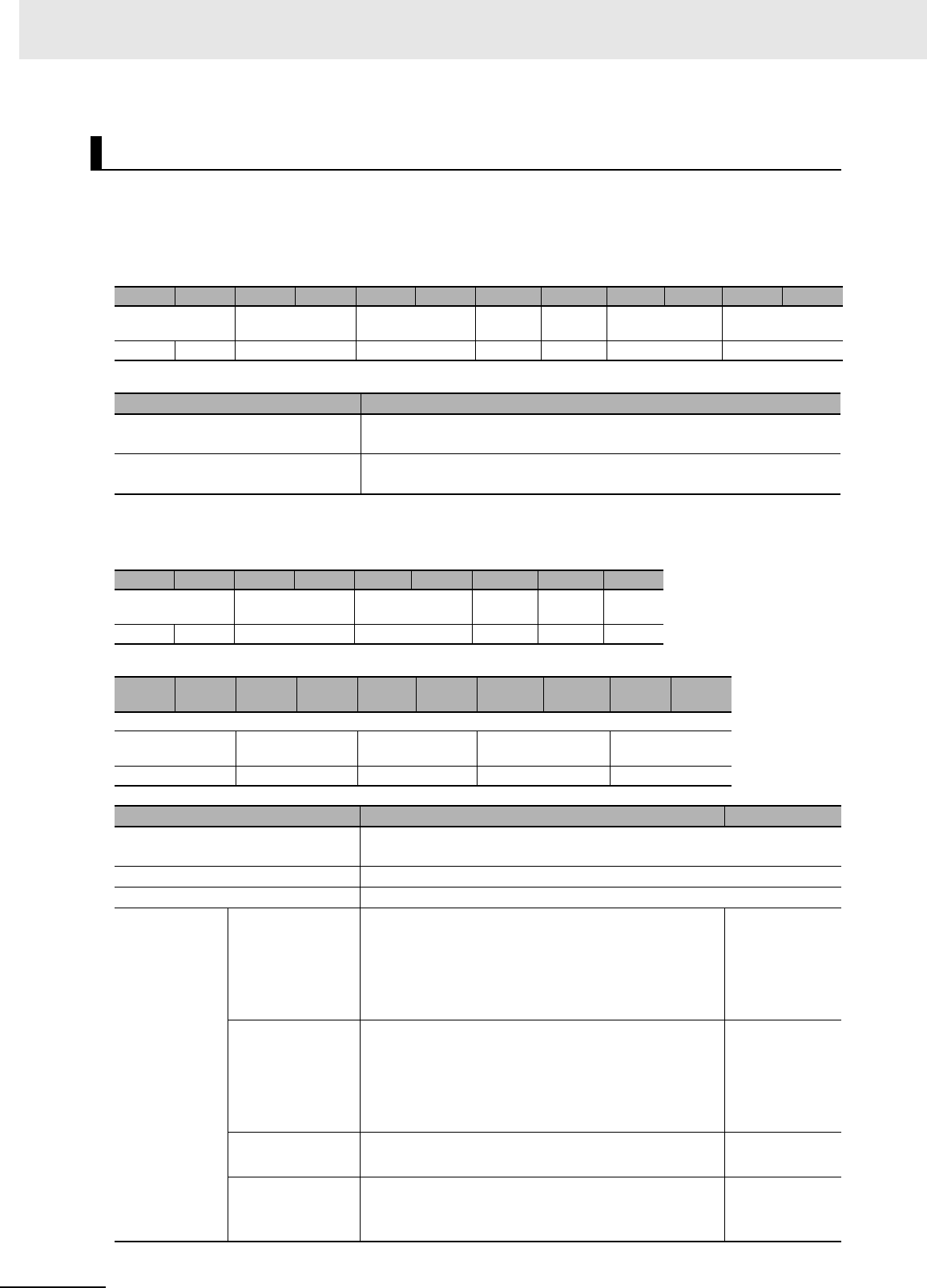
7 Modbus/TCP Communications
7 - 72 UHF RFID System V780-series Reader/Writer User’s Manual (Z389)
Function
This command is used to check the RF communications conditions that are set in the Reader/Writer.
Command Format
Response Formats
• Normal Response
GET TAG COMMUNICATIONS CONDITIONS
Byte-0 Byte-1 Byte-2 Byte-3 Byte-4 Byte-5 Byte-6 Byte-7 Byte-8 Byte-9 Byte-10 Byte-11
Transaction identi-
fier
Protocol identifier Field length Unit
identifier
Function
code
Register address Word count
X X 0000 hex 0006 hex FF hex 03 hex C000 hex 0005 hex
Parameter Description
Register address The register address (C000 hex) that specifies the RF communications
conditions
Word count The number of words of the RF communications conditions to read (0005
hex)
Byte-0 Byte-1 Byte-2 Byte-3 Byte-4 Byte-5 Byte-6 Byte-7 Byte-8
Transaction identi-
fier
Protocol identifier Field length Unit
identifier
Function
code
Byte
count
X X 0000 hex 000D hex FF hex 03 hex 0A hex
Byte-9 Byte-10 Byte-11 Byte-12 Byte-1
3Byte-14 Byte-15 Byte-16 Byte-17 Byte-18
Communications conditions
RF communica-
tions mode
RF communica-
tions speed
RF communica-
tions timeout time
Write verification Reserved
2 bytes 2 bytes 2 bytes 2 bytes 0000 hex
Parameter Description Default setting
Register address The register address (C000 hex) that specifies the RF communications
conditions
Word count The number of words in the RF communications conditions (0005 hex)
Byte count The number of bytes in the RF communications conditions (0A hex)
Communica-
tions conditions
RF communica-
tions mode
Gives the communications mode in 4-digit hexadeci-
mal.
0000 hex: Once
0001 hex: Auto
0002 hex: Focus
0000 hex
RF communica-
tions speed
Gives the communications speed in 4-digit hexadeci-
mal.
0000 hex: Automatic (default)
0001 hex: High speed
0002 hex: Normal speed
0000 hex
RF communica-
tions timeout time
Gives the RF communications timeout time.
0001 to EA60 hex (1 to 60,000 [ms])
00FA hex
(250)
Write verification Gives whether write verification is being performed in
4-digit hexadecimal.
0000 hex: Disable, 0001 hex: Enable
0001 hex

7 - 73
7 Modbus/TCP Communications
UHF RFID System V780-series Reader/Writer User’s Manual (Z389)
7-6 V780 Command Details
7
7-6-6 Reader/Writer Setting Commands: Communications Settings
• Error Response
Execution Examples
Execution When the Following RF Communications Conditions Are Set in the Reader/Writer
RF communications mode: Once, RF communications speed: Auto, RF communications timeout
time: 250 ms, Write verification: Enabled
TX: 000000000006FF03C0000005
RX: 00000000000DFF030A0000000000FA00010000
Byte-0 Byte-1 Byte-2 Byte-3 Byte-4 Byte-5 Byte-6 Byte-7 Byte-8
Transaction identi-
fier
Protocol identifier Field length Unit
identifier
Function
code
Excep-
tion code
X X 0000 hex 0003 hex FF hex 83 hex 1 byte
Parameter Description
Exception code For details, refer to Exception Code on page 7-7 under 7-2-3 Response Format for
Error Completion on page 7-7.
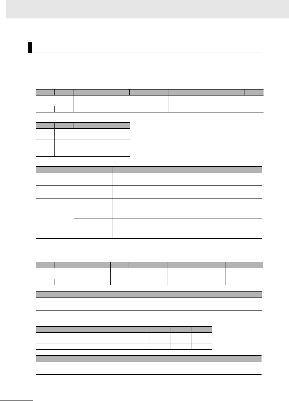
7 Modbus/TCP Communications
7 - 74 UHF RFID System V780-series Reader/Writer User’s Manual (Z389)
Function
This command sets the transmission powers of the Reader/Writer.
Command Format
Response Formats
• Normal Response
• Error Response
SET TRANSMISSION POWER
Byte-0 Byte-1 Byte-2 Byte-3 Byte-4 Byte-5 Byte-6 Byte-7 Byte-8 Byte-9 Byte-10 Byte-11
Transaction identi-
fier
Protocol identifier Field length Unit
identifier
Function
code
Register address Word count
X X 0000 hex 000B hex FF hex 10 hex C100 hex 0002 hex
Byte-12 Byte-13 Byte-14 Byte-15 Byte-16
Byte
count
Transmission power
04 hex Read transmis-
sion power
Write transmis-
sion power
2 bytes 2 bytes
Parameter Description Default setting
Register address The register address (C100 hex) that specifies setting the transmission
powers
Word count The number of words in the transmission power settings (0002 hex)
Byte count The number of bytes in the transmission power setting (04 hex)
Transmission
power
Read transmis-
sion power
Specify the transmission power for read RF communi-
cations commands in 4-digit hexadecimal.
000F to 001B hex (15 to 27 dBm)
001B hex
(27 [dBm])
Write transmis-
sion power
Specify the transmission power for write RF communi-
cations commands in 4-digit hexadecimal.
000F to 001B hex (15 to 27 dBm)
001B hex
(27 [dBm])
Byte-0 Byte-1 Byte-2 Byte-3 Byte-4 Byte-5 Byte-6 Byte-7 Byte-8 Byte-9 Byte-10 Byte-11
Transaction identi-
fier
Protocol identifier Field length Unit
identifier
Function
code
Register address Word count
X X 0000 hex 0006 hex FF hex 10 hex C100 hex 0002 hex
Parameter Description
Register address The register address from the command is set.
Word count The word count from the command is set.
Byte-0 Byte-1 Byte-2 Byte-3 Byte-4 Byte-5 Byte-6 Byte-7 Byte-8
Transaction identi-
fier
Protocol identifier Field length Unit
identifier
Function
code
Excep-
tion code
X X 0000 hex 0003 hex FF hex 90 hex 1 byte
Parameter Description
Exception code For details, refer to Exception Code on page 7-7 under 7-2-3 Response Format for
Error Completion on page 7-7.

7 - 75
7 Modbus/TCP Communications
UHF RFID System V780-series Reader/Writer User’s Manual (Z389)
7-6 V780 Command Details
7
7-6-6 Reader/Writer Setting Commands: Communications Settings
Execution Examples
Execution to Set the Following Transmission Powers in the Reader/Writer
Read transmission power: 27 dBm, Write transmission power: 27 dBm
TX: 00000000000BFF10C100000204001B001B
RX: 000000000006FF10C1000002
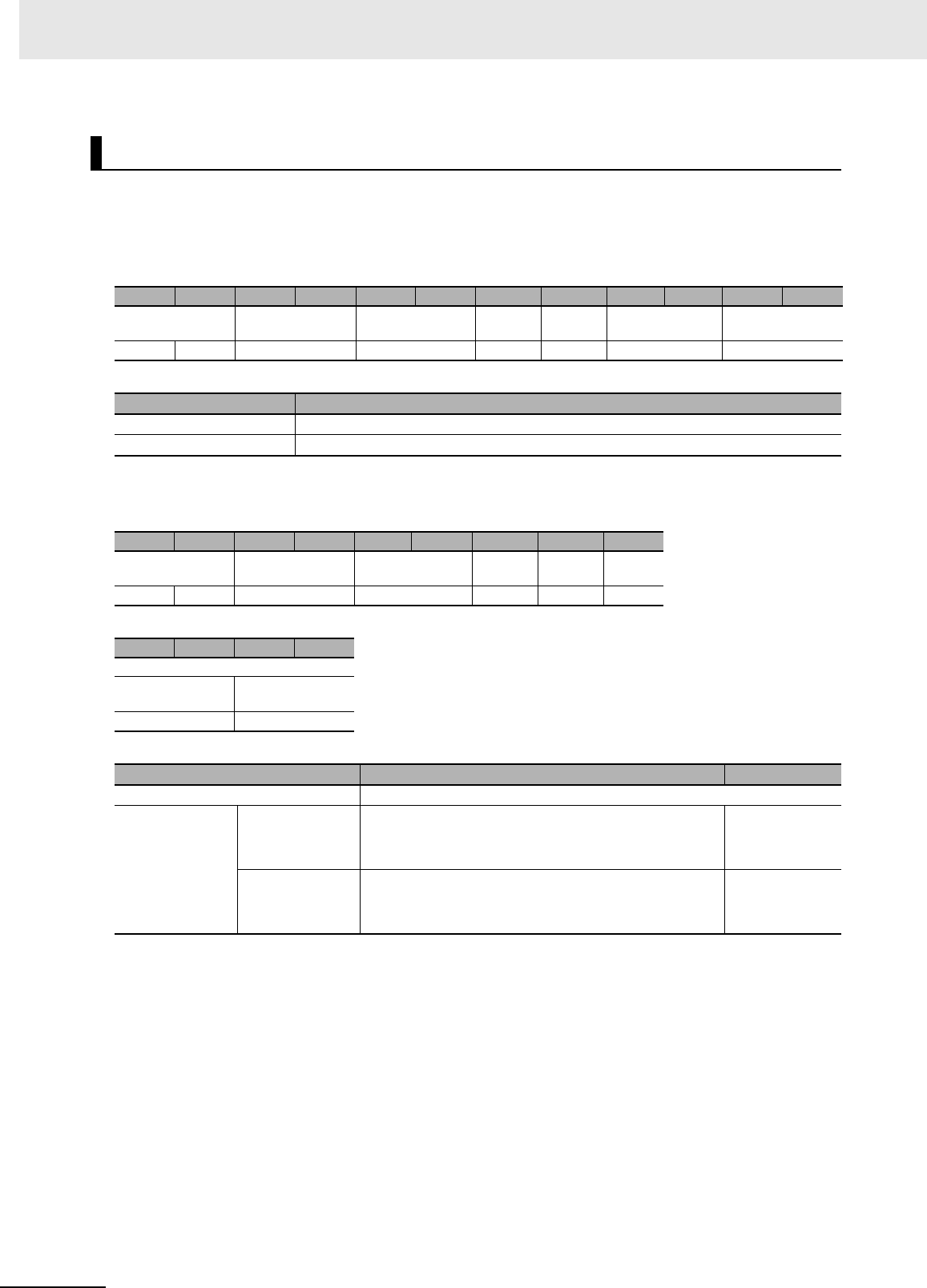
7 Modbus/TCP Communications
7 - 76 UHF RFID System V780-series Reader/Writer User’s Manual (Z389)
Function
This command is used to check the transmission powers that are set in the Reader/Writer.
Command Format
Response Formats
• Normal Response
Execution Examples
Execution When the Following RF Transmission Powers Are Set in the Reader/Writer
Read transmission power: 27 dBm, Write transmission power: 27dBm
TX: 000000000006FF03C1000002
RX: 000000000007FF0304001B001B
GET TRANSMISSION POWER
Byte-0 Byte-1 Byte-2 Byte-3 Byte-4 Byte-5 Byte-6 Byte-7 Byte-8 Byte-9 Byte-10 Byte-11
Transaction identi-
fier
Protocol identifier Field length Unit
identifier
Function
code
Register address Word count
X X 0000 hex 0006 hex FF hex 03 hex C100 hex 0002 hex
Parameter Description
Register address The register address (C100 hex) that specifies setting the transmission power
Word count The number of words of the antenna setting to read (0002 hex)
Byte-0 Byte-1 Byte-2 Byte-3 Byte-4 Byte-5 Byte-6 Byte-7 Byte-8
Transaction identi-
fier
Protocol identifier Field length Unit
identifier
Function
code
Byte
count
X X 0000 hex 0007 hex FF hex 03 hex 04 hex
Byte-9 Byte-10 Byte-11 Byte-12
Transmission powers
Read transmis-
sion power
Write transmis-
sion power
2 bytes 2 bytes
Parameter Description Default setting
Byte count The number of bytes in the transmission powers (06 hex)
Transmission
power
Read transmis-
sion power
Gives the transmission power for read RF communica-
tions commands in 4-digit hexadecimal.
000F to 001B hex (15 to 27 dBm)
001B hex
(27 [dBm])
Write transmis-
sion power
Gives the transmission power for write RF communica-
tions commands in 4-digit hexadecimal.
000F to 001B hex (15 to 27 dBm)
001B hex
(27 [dBm])
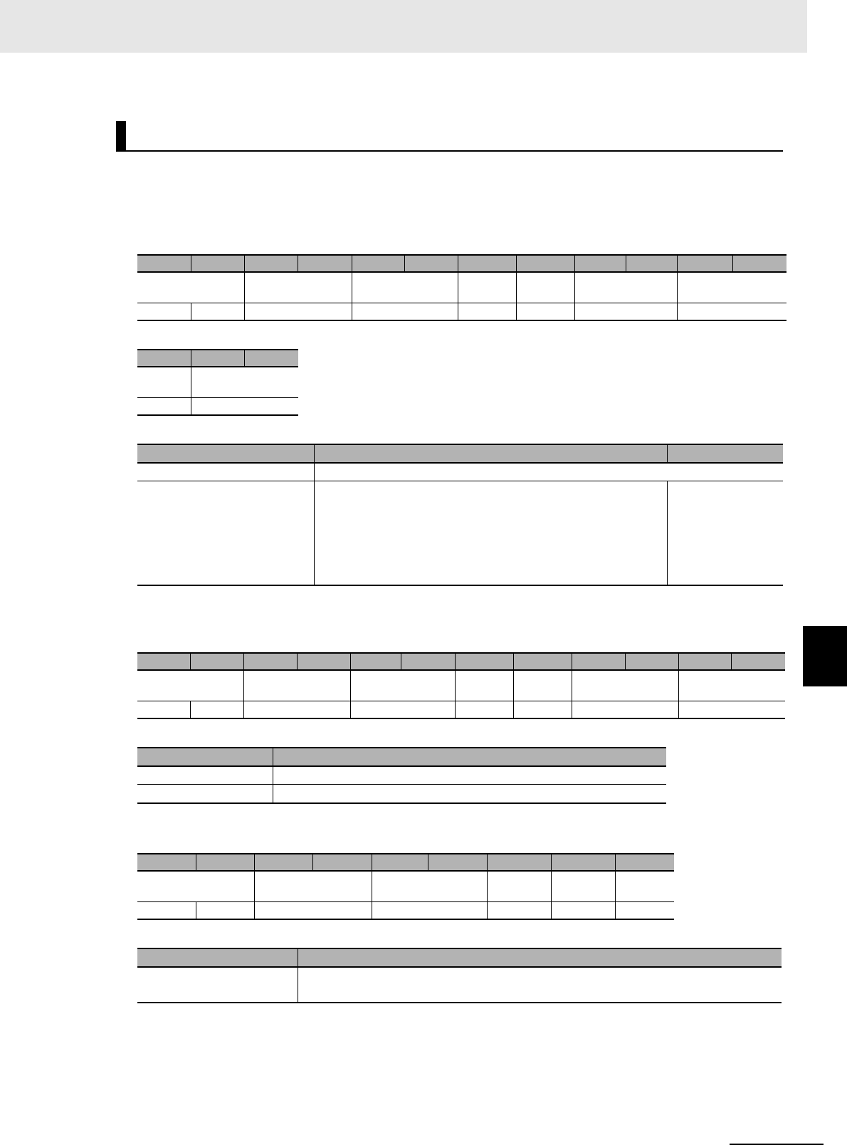
7 - 77
7 Modbus/TCP Communications
UHF RFID System V780-series Reader/Writer User’s Manual (Z389)
7-6 V780 Command Details
7
7-6-6 Reader/Writer Setting Commands: Communications Settings
Function
This command sets the channel in the Reader/Writer.
Command Format
Response Formats
• Normal Response
• Error Response
SET CHANNEL
Byte-0 Byte-1 Byte-2 Byte-3 Byte-4 Byte-5 Byte-6 Byte-7 Byte-8 Byte-9 Byte-10 Byte-11
Transaction identi-
fier
Protocol identifier Field length Unit
identifier
Function
code
Register address Word count
X X 0000 hex 0009 hex FF hex 10 hex C200 hex 0001 hex
Byte-12 Byte-13 Byte-14
Byte
count
Channel
02 hex 2 bytes
Parameter Description Default setting
Register address The register address (C200 hex) that specifies the channel
Channel Specify the channel in 4-digit hexadecimal.
0000 hex: Auto
0002 hex: Channel 2
0008 hex: Channel 8
000E hex: Channel 14
0000 hex
Byte-0 Byte-1 Byte-2 Byte-3 Byte-4 Byte-5 Byte-6 Byte-7 Byte-8 Byte-9 Byte-10 Byte-11
Transaction identi-
fier
Protocol identifier Field length Unit
identifier
Function
code
Register address Word count
X X 0000 hex 0006 hex FF hex 10 hex C200 hex 0001 hex
Parameter Description
Register address The register address from the command is set.
Word count The word count from the command is set.
Byte-0 Byte-1 Byte-2 Byte-3 Byte-4 Byte-5 Byte-6 Byte-7 Byte-8
Transaction identifier Protocol identifier Field length Unit iden-
tifier
Function
code
Excep-
tion code
X X 0000 hex 0003 hex FF hex 90 hex 1 byte
Parameter Description
Exception code For details, refer to Exception Code on page 7-7 under 7-2-3 Response Format for
Error Completion on page 7-7.

7 Modbus/TCP Communications
7 - 78 UHF RFID System V780-series Reader/Writer User’s Manual (Z389)
Execution Examples
Execution to Set Channel 2 for the Reader/Writer
TX: 000000000009FF10C2000001020002
RX: 000000000006FF10C2000001
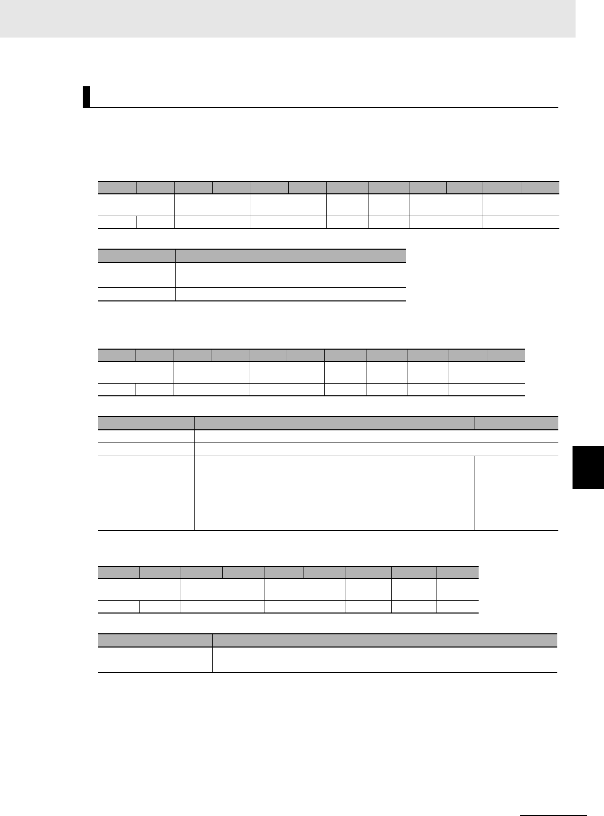
7 - 79
7 Modbus/TCP Communications
UHF RFID System V780-series Reader/Writer User’s Manual (Z389)
7-6 V780 Command Details
7
7-6-6 Reader/Writer Setting Commands: Communications Settings
Function
This command is used to check the channel that is set in the Reader/Writer.
Command Format
Response Formats
• Normal Response
• Error Response
Execution Examples
Execution When Channel 2 Is Set for the Reader/Writer
TX: 000000000006FF03C2000001
RX: 000000000005FF03020002
GET CHANNEL
Byte-0 Byte-1 Byte-2 Byte-3 Byte-4 Byte-5 Byte-6 Byte-7 Byte-8 Byte-9 Byte-10 Byte-11
Transaction identi-
fier
Protocol identifier Field length Unit
identifier
Function
code
Register address Word count
X X 0000 hex 0006 hex FF hex 03 hex C200 hex 1 byte
Parameter Description
Register address The register address (C200 hex) that specifies the
channel
Word count Always 0001 hex.
Byte-0 Byte-1 Byte-2 Byte-3 Byte-4 Byte-5 Byte-6 Byte-7 Byte-8 Byte-9 Byte-10
Transaction identi-
fier
Protocol identifier Field length Unit
identifier
Function
code
Byte
count
Channel
X X 0000 hex 0005 hex FF hex 03 hex 02 hex 2 bytes
Parameter Description Default setting
Field length Always 0005 hex.
Byte count Always 02 hex.
Channel Gives the channel in 4-digit hexadecimal.
0000 hex: Auto
0002 hex: Channel 2
0008 hex: Channel 8
000E hex: Channel 14
0000 hex
Byte-0 Byte-1 Byte-2 Byte-3 Byte-4 Byte-5 Byte-6 Byte-7 Byte-8
Transaction identifier Protocol identifier Field length Unit iden-
tifier
Function
code
Excep-
tion code
X X 0000 hex 0003 hex FF hex 83 hex 1 byte
Parameter Description
Exception code For details, refer to Exception Code on page 7-7 under 7-2-3 Response Format for
Error Completion on page 7-7.
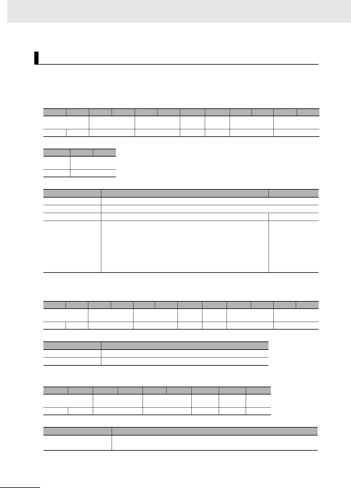
7 Modbus/TCP Communications
7 - 80 UHF RFID System V780-series Reader/Writer User’s Manual (Z389)
Function
This command sets the Gen2 session for the Reader/Writer.
Command Format
Response Formats
• Normal Response
• Error Response
SET GEN2 SESSION
Byte-0 Byte-1 Byte-2 Byte-3 Byte-4 Byte-5 Byte-6 Byte-7 Byte-8 Byte-9 Byte-10 Byte-11
Transaction identi-
fier
Protocol identifier Field length Unit
identifier
Function
code
Register address Word count
X X 0000 hex 009 hex FF hex 10 hex C300 hex 0001 hex
Byte-12 Byte-13 Byte-14
Byte
count
Gen2 Session
02 hex 2 bytes
Parameter Description Default setting
Register address The register address (C300 hex) that specifies the Gen2 session setting
Word count The number of words in the Gen2 session setting (0001 hex)
Byte count The number of bytes in the Gen2 session setting (02 hex)
Gen2 session Specify the session to use for RF Tag communications in 4-digit
hexadecimal.
0000 hex: S0 flag
0001 hex: S1 flag
0002 hex: S2 flag
0003 hex: S3 flag
0000 hex
Byte-0 Byte-1 Byte-2 Byte-3 Byte-4 Byte-5 Byte-6 Byte-7 Byte-8 Byte-9 Byte-10 Byte-11
Transaction identi-
fier
Protocol identifier Field length Unit
identifier
Func-
tion code
Register address Word count
X X 0000 hex 0006 hex FF hex 10 hex C300 hex 0001 hex
Parameter Description
Register address The register address from the command is set.
Word count The word count from the command is set.
Byte-0 Byte-1 Byte-2 Byte-3 Byte-4 Byte-5 Byte-6 Byte-7 Byte-8
Transaction identifier Protocol identifier Field length Unit iden-
tifier
Function
code
Excep-
tion code
X X 0000 hex 0003 hex FF hex 90 hex 1 byte
Parameter Description
Exception code For details, refer to Exception Code on page 7-7 under 7-2-3 Response Format for
Error Completion on page 7-7.

7 - 81
7 Modbus/TCP Communications
UHF RFID System V780-series Reader/Writer User’s Manual (Z389)
7-6 V780 Command Details
7
7-6-6 Reader/Writer Setting Commands: Communications Settings
Execution Examples
Execution to Set S2 as the Gen2 Session for the Reader/Writer
TX: 000000000009FF10C3000001020002
RX: 000000000006FF10C3000001
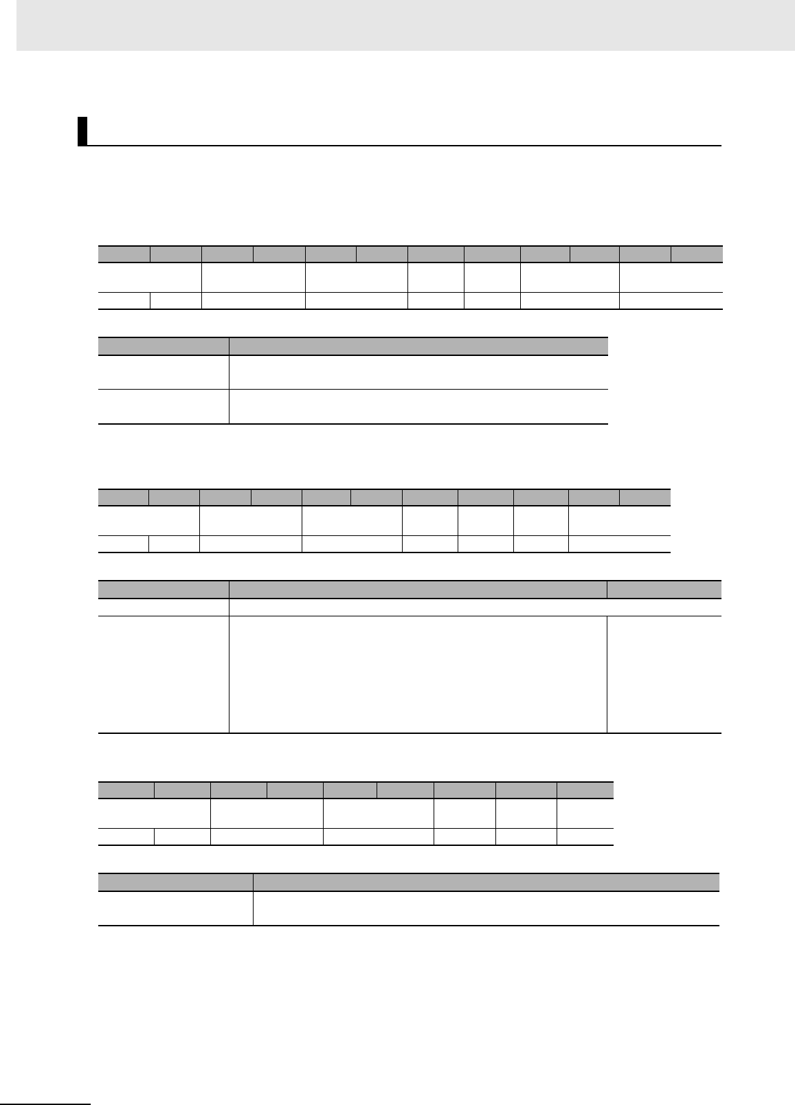
7 Modbus/TCP Communications
7 - 82 UHF RFID System V780-series Reader/Writer User’s Manual (Z389)
Function
This command is used to check the Gen2 session that is set in the Reader/Writer.
Command Format
Response Formats
• Normal Response
• Error Response
Execution Examples
Execution When S2 Is Set as the Gen2 Session for the Reader/Writer
TX: 000000000006FF03C3000001
RX: 000000000005FF03020002
GET GEN2 SESSION
Byte-0 Byte-1 Byte-2 Byte-3 Byte-4 Byte-5 Byte-6 Byte-7 Byte-8 Byte-9 Byte-10 Byte-11
Transaction identi-
fier
Protocol identifier Field length Unit
identifier
Function
code
Register address Word count
X X 0000 hex 0006 hex FF hex 03 hex C300 hex 0001 hex
Parameter Description
Register address The register address (C300 hex) that specifies the Gen2 session
setting
Word count The number of words in the Gen2 session setting to read (0001
hex)
Byte-0 Byte-1 Byte-2 Byte-3 Byte-4 Byte-5 Byte-6 Byte-7 Byte-8 Byte-9 Byte-10
Transaction identi-
fier
Protocol identifier Field length Unit
identifier
Func-
tion code
Byte
count
Gen2 session
X X 0000 hex 0005 hex FF hex 03 hex 02 hex 2 bytes
Parameter Description Default setting
Byte count The number of bytes in the Gen2 session setting that was read (02 hex)
Gen2 session Gives the session that is being used for RF Tag communications in
4-digit hexadecimal.
0000 hex: S0 flag (default)
0001 hex: S1 flag
0002 hex: S2 flag
0003 hex: S3 flag
0000 hex
Byte-0 Byte-1 Byte-2 Byte-3 Byte-4 Byte-5 Byte-6 Byte-7 Byte-8
Transaction identifier Protocol identifier Field length Unit iden-
tifier
Function
code
Excep-
tion code
X X 0000 hex 0003 hex FF hex 83 hex 1 byte
Parameter Description
Exception code For details, refer to Exception Code on page 7-7 under 7-2-3 Response Format for
Error Completion on page 7-7.
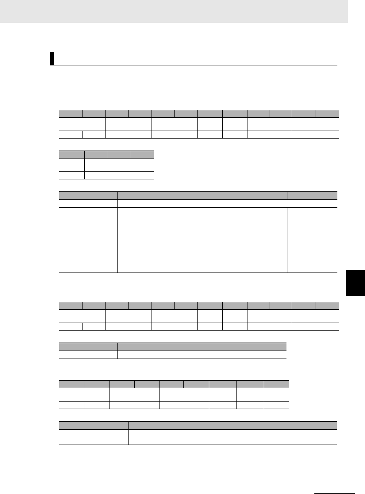
7 - 83
7 Modbus/TCP Communications
UHF RFID System V780-series Reader/Writer User’s Manual (Z389)
7-6 V780 Command Details
7
7-6-6 Reader/Writer Setting Commands: Communications Settings
Function
This command sets the access password for RF Tag communications of the Reader/Writer.
Command Format
Response Formats
• Normal Response
• Error Response
SET ACCESS PASSWORD
Byte-0 Byte-1 Byte-2 Byte-3 Byte-4 Byte-5 Byte-6 Byte-7 Byte-8 Byte-9 Byte-10 Byte-11
Transaction identi-
fier
Protocol identifier Field length Unit
identifier
Function
code
Register address Word count
X X 0000 hex 000B hex FF hex 10 hex C400 hex 0002 hex
Byte-12 Byte-13 ... Byte-16
Byte
count
Access password
04 hex 4 bytes
Parameter Description Default setting
Register address The register address (C400 hex) that specifies the access password setting
Access password Specify the access password to use for RF Tag communications in
8-digit hexadecimal.
The specified access password is stored in EEPROM memory in
the Reader/Writer.
If the access password in the RF Tag is not all zeros, the access
password that is stored in EEPROM memory must be used to exe-
cute LOCK, WRITE ID, READ DATA, or WRITE DATA commands.
00000000 hex
Byte-0 Byte-1 Byte-2 Byte-3 Byte-4 Byte-5 Byte-6 Byte-7 Byte-8 Byte-9 Byte-10 Byte-11
Transaction identi-
fier
Protocol identifier Field length Unit
identifier
Function
code
Register address Word count
X X 0000 hex 0006 hex FF hex 10 hex C400 hex 0002 hex
Parameter Description
Word count Always 0002 hex.
Byte-0 Byte-1 Byte-2 Byte-3 Byte-4 Byte-5 Byte-6 Byte-7 Byte-8
Transaction identifier Protocol identifier Field length Unit iden-
tifier
Function
code
Excep-
tion code
X X 0000 hex 0003 hex FF hex 90 hex 1 byte
Parameter Description
Exception code For details, refer to Exception Code on page 7-7 under 7-2-3 Response Format for
Error Completion on page 7-7.

7 Modbus/TCP Communications
7 - 84 UHF RFID System V780-series Reader/Writer User’s Manual (Z389)
Execution Examples
Execution to Set the Reader/Writer Access Password to “12345678 hex”
TX: 00000000000BFF10C40000020412345678
RX: 000000000006FF10C4000002
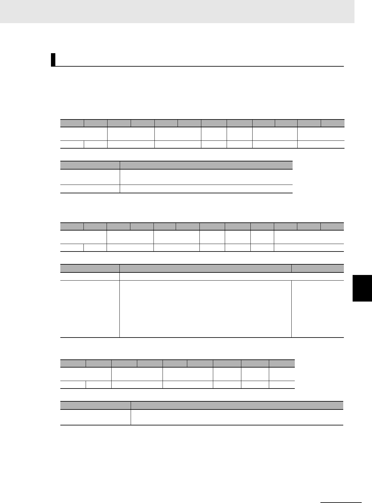
7 - 85
7 Modbus/TCP Communications
UHF RFID System V780-series Reader/Writer User’s Manual (Z389)
7-6 V780 Command Details
7
7-6-6 Reader/Writer Setting Commands: Communications Settings
Function
This command reads the access password that is set for RF Tag communications in the
Reader/Writer.
Command Format
Response Formats
• Normal Response
• Error Response
Execution Examples
Execution When the Reader/Writer Access Password Is Set to “12345678 hex”
TX: 000000000006FF03C4000002
RX: 000000000007FF030412345678
GET ACCESS PASSWORD
Byte-0 Byte-1 Byte-2 Byte-3 Byte-4 Byte-5 Byte-6 Byte-7 Byte-8 Byte-9 Byte-10 Byte-11
Transaction identi-
fier
Protocol identifier Field length Unit
identifier
Function
code
Register address Word count
X X 0000 hex 0006 hex FF hex 03 hex C400 hex 0002 hex
Parameter Description
Register address The register address (C400 hex) that specifies reading the access
password
Word count The number of words in the access password to read (0002 hex)
Byte-0 Byte-1 Byte-2 Byte-3 Byte-4 Byte-5 Byte-6 Byte-7 Byte-8 Byte-9 ... Byte-12
Transaction identi-
fier
Protocol identifier Field length Unit
identifier
Function
code
Byte
count
Access password
X X 0000 hex 0007 hex FF hex 03 hex 04 hex 4 bytes
Parameter Description Default setting
Byte count The number of bytes in the access password (04 hex)
Access password Gives the access password to use for RF Tag communications in
8-digit hexadecimal.
The specified access password is stored in EEPROM memory in
the Reader/Writer.
If the access password in the RF Tag is not all zeros, the access
password that is stored in EEPROM memory must be used to exe-
cute LOCK, WRITE ID, READ DATA, or WRITE DATA commands.
00000000 hex
Byte-0 Byte-1 Byte-2 Byte-3 Byte-4 Byte-5 Byte-6 Byte-7 Byte-8
Transaction identifier Protocol identifier Field length Unit iden-
tifier
Function
code
Excep-
tion code
X X 0000 hex 0003 hex FF hex 83 hex 1 byte
Parameter Description
Exception code For details, refer to Exception Code on page 7-7 under 7-2-3 Response Format for
Error Completion on page 7-7.
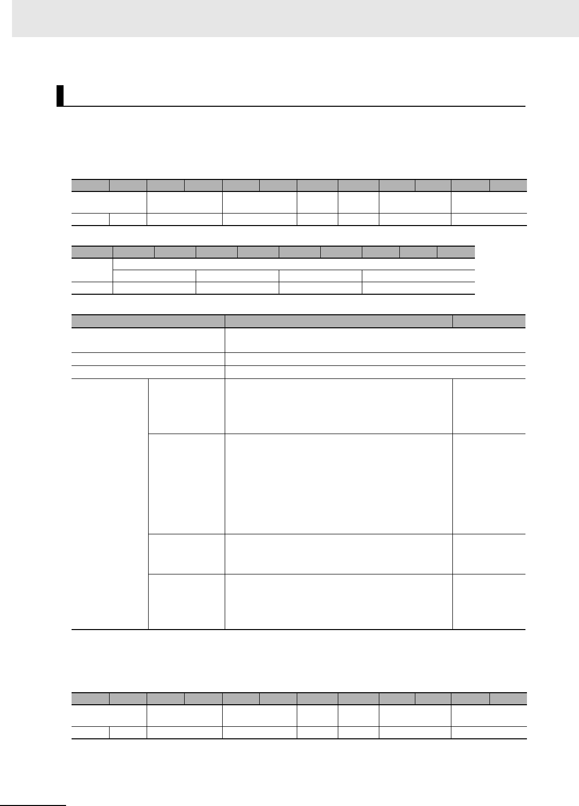
7 Modbus/TCP Communications
7 - 86 UHF RFID System V780-series Reader/Writer User’s Manual (Z389)
Function
This command sets the RF Tag selection filter conditions for the Reader/Writer.
Command Format
*1. If the RF Tag selection filter conditions settings are disabled, this value is always 0000 hex.
Response Formats
• Normal Response
SET RF TAG SELECTION FILTER CONDITIONS
Byte-0 Byte-1 Byte-2 Byte-3 Byte-4 Byte-5 Byte-6 Byte-7 Byte-8 Byte-9 Byte-10 Byte-11
Transaction identi-
fier
Protocol identifier Field length Unit
identifier
Function
code
Register address Word count
X X 0000 hex 002D hex FF hex 10 hex C500 hex 0013 hex
Byte-12 Byte-13 Byte-14 Byte-15 Byte-16 Byte-17 Byte-18 Byte-19 ... Byte-50
Byte
count
RF Tag selection filter conditions
Enable/disable Address Data length Data
26 hex 2 bytes 2 bytes 2 bytes 32 bytes
Parameter Description Default setting
Register address The register address (C500 hex) that specifies setting the RF Tag selec-
tion filter conditions
Word count The number of words in the RF Tag selection filter conditions (0013 hex)
Byte count The number of bytes in the RF Tag selection filter conditions (26 hex)
RF Tag selection
filter conditions
Enable/disable Specify whether to enable or disable RF Tag selection
filter conditions in 4-digit hexadecimal.
0000 hex: Disable
0001 hex: Enable
0000 hex
Address*1. Set the address (in words) of the RF Tag to check for in
4-digit hexadecimal.
Setting ranges (word address specifications)
1000 to 17FF hex: EPC area
2000 to 27FF hex: TID area
3000 to 37FF hex: User area
*You cannot specify 0000 to 07FF hex (reserved area).
0000 hex
Data length*1. Specify the number of words of data to check in 4-digit
hexadecimal.
Setting range: 0000 to 0010 hex
0000 hex
Data*1. Specify the data to check for. (Always 16 words.)
*Fill unused data with 0000 hex.
*In compliance with Gen2 standards, bits 0 to 255 are
masked, so the last bit of word 16 (bit 256) is ignored.
00....00 hex
Byte-0 Byte-1 Byte-2 Byte-3 Byte-4 Byte-5 Byte-6 Byte-7 Byte-8 Byte-9 Byte-10 Byte-11
Transaction identi-
fier
Protocol identifier Field length Unit
identifier
Function
code
Register address Word count
X X 0000 hex 0006 hex FF hex 10 hex C500 hex 0013 hex
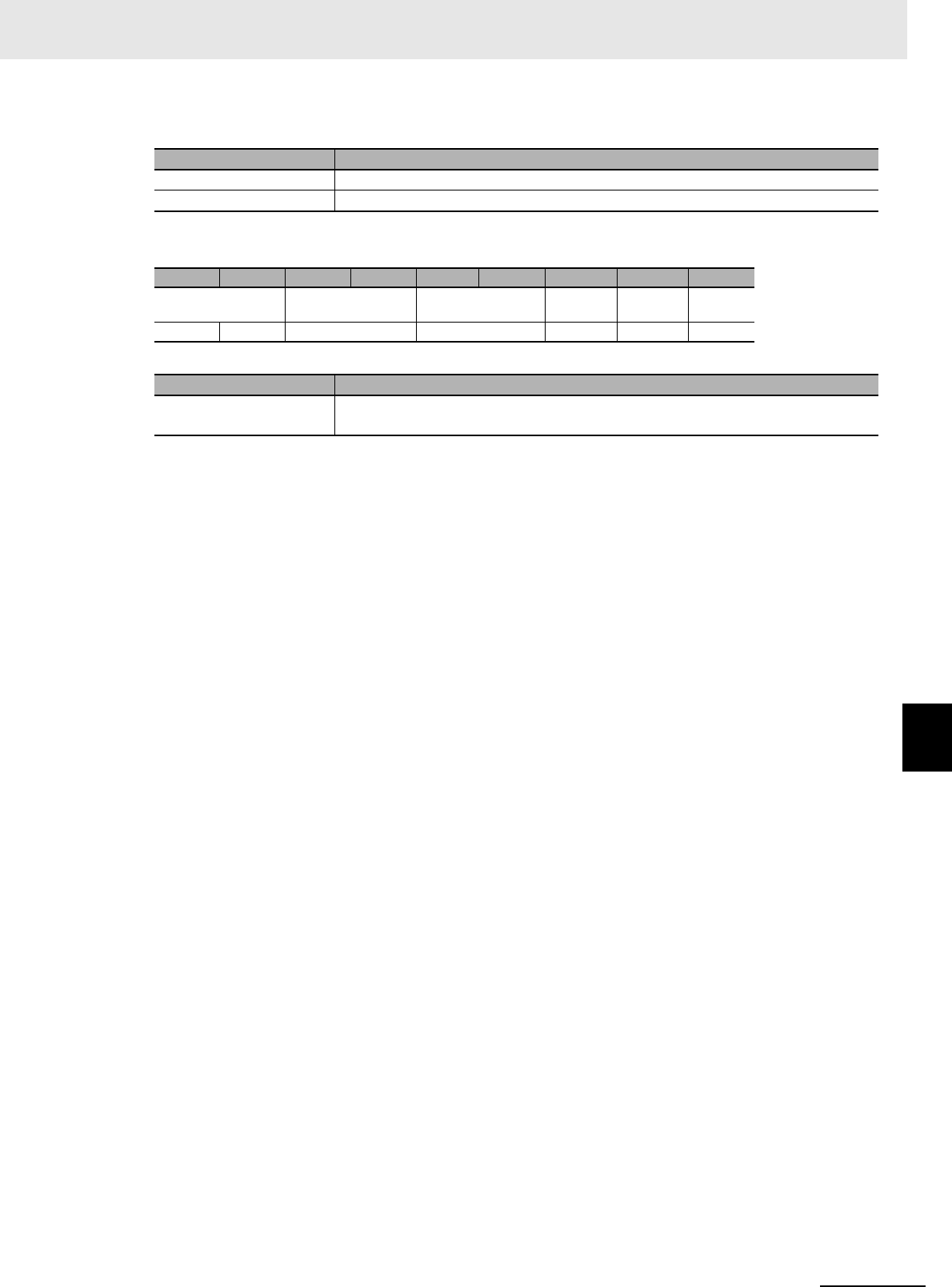
7 - 87
7 Modbus/TCP Communications
UHF RFID System V780-series Reader/Writer User’s Manual (Z389)
7-6 V780 Command Details
7
7-6-6 Reader/Writer Setting Commands: Communications Settings
• Error Response
Execution Examples
Example 1: Execution When Enabling RF Tag Selection Filter Conditions for the Reader/Writer with
the Following Settings
Address: 3000 hex, Data length: 1 word, Data to check for: 1234 hex
TX: 00000000002DFF10C500001326000130000001123400…00
RX: 000000000006FF10C5000013
Example 2: Execution When Disabling RF Tag Selection Filter Conditions for the Reader/Writer
TX: 00000000002DFF10C50000132600000000000000000…00
RX: 000000000006FF10C5000013
Parameter Description
Register address The register address from the command is set.
Word count The word count from the command is set.
Byte-0 Byte-1 Byte-2 Byte-3 Byte-4 Byte-5 Byte-6 Byte-7 Byte-8
Transaction identifier Protocol identifier Field length Unit iden-
tifier
Function
code
Excep-
tion code
X X 0000 hex 0003 hex FF hex 90 hex 1 byte
Parameter Description
Exception code For details, refer to Exception Code on page 7-7 under 7-2-3 Response Format for
Error Completion on page 7-7.
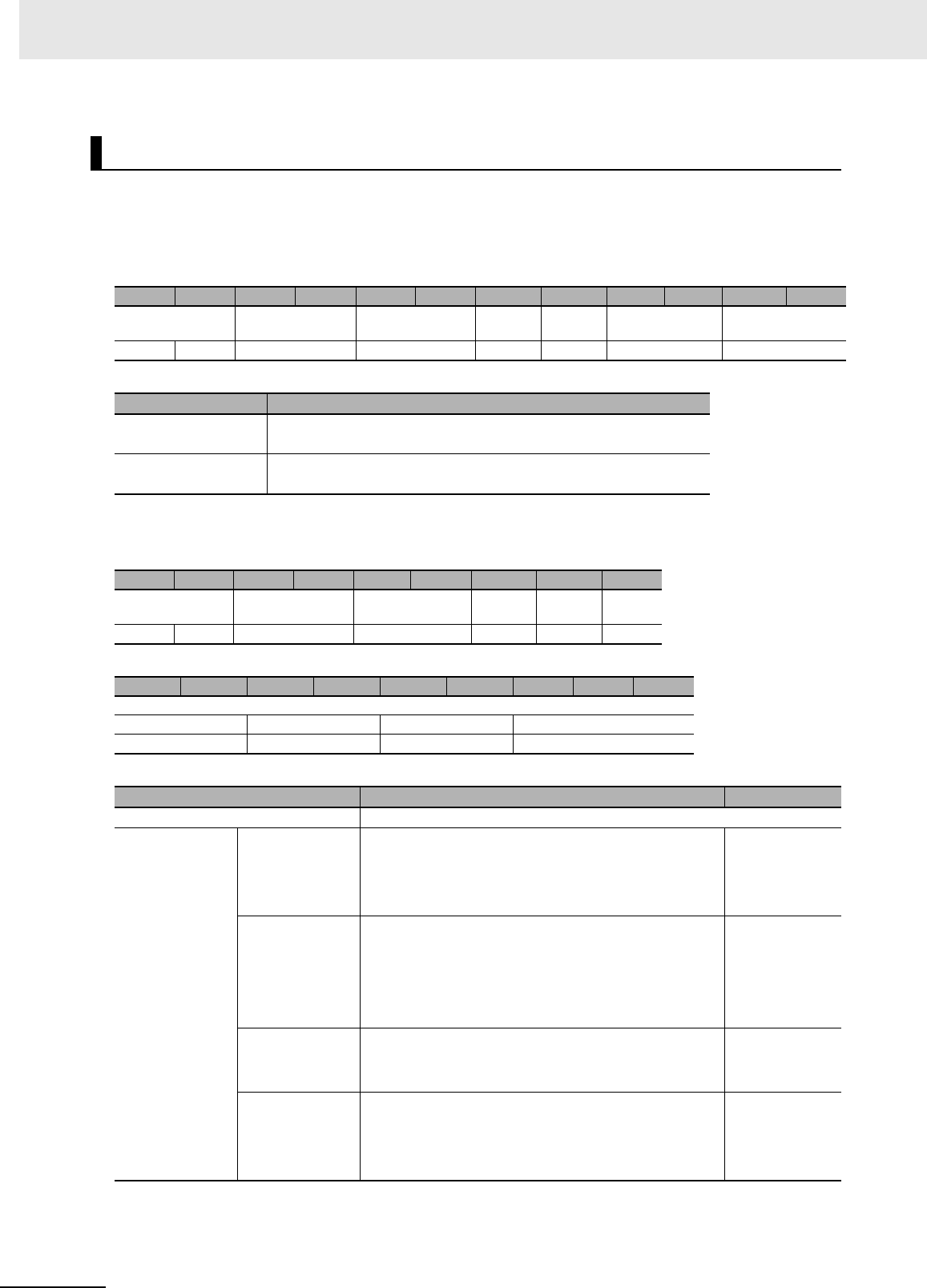
7 Modbus/TCP Communications
7 - 88 UHF RFID System V780-series Reader/Writer User’s Manual (Z389)
Function
This command reads the RF Tag selection filter conditions that are set in the Reader/Writer.
Command Format
Response Formats
• Normal Response
*1. If the RF Tag selection filter conditions settings are being disabled, this value is always 0000 hex.
GET RF TAG SELECTION FILTER CONDITIONS
Byte-0 Byte-1 Byte-2 Byte-3 Byte-4 Byte-5 Byte-6 Byte-7 Byte-8 Byte-9 Byte-10 Byte-11
Transaction identi-
fier
Protocol identifier Field length Unit
identifier
Function
code
Register address Word count
X X 0000 hex 0006 hex FF hex 03 hex C500 hex 0013 hex
Parameter Description
Register address The register address (C500 hex) that specifies setting the RF Tag
selection filter conditions
Word count The number of words in the RF Tag selection filter conditions to
read (0013 hex)
Byte-0 Byte-1 Byte-2 Byte-3 Byte-4 Byte-5 Byte-6 Byte-7 Byte-8
Transaction identi-
fier
Protocol identifier Field length Unit
identifier
Function
code
Byte
count
X X 0000 hex 0028 hex FF hex 03 hex 26 hex
Byte-9 Byte-10 Byte-11 Byte-12 Byte-13 Byte-14 Byte-15 ... Byte-46
RF Tag selection filter conditions
Enable/disable Address Data length Data
2 bytes 2 bytes 2 bytes 32 bytes
Parameter Description Default setting
Byte count The number of bytes in the RF Tag selection filter conditions (26 hex)
RF Tag selection
filter conditions
Enable/disable Gives whether RF Tag selection filter conditions are
enabled or disabled in 4-digit hexadecimal.
0000 hex: Disable
0001 hex: Enable
0000 hex
Address*1. Gives the address (in words) of the RF Tag to check for
in 4-digit hexadecimal.
1000 to 17FF hex: EPC area
2000 to 27FF hex: TID area
3000 to 37FF hex: User area
0000 hex
Data length*1. Gives the number of words of data to check in 4-digit
hexadecimal.
0000 to 0010 hex
0000 hex
Data*1. Gives the data to check for. (Always 16 words.)
*Unused data is filled with 0000 hex.
*In compliance with Gen2 standards, bits 0 to 255 are
masked, so the last bit of word 16 (bit 256) is ignored.
00....00 hex

7 - 89
7 Modbus/TCP Communications
UHF RFID System V780-series Reader/Writer User’s Manual (Z389)
7-6 V780 Command Details
7
7-6-6 Reader/Writer Setting Commands: Communications Settings
• Error Response
Execution Examples
Execution When RF Tag Selection Filter Conditions for the Reader/Writer Are Enabled with the Fol-
lowing Settings
Address: 3000 hex, Data length: 1 word, Data to check: 1234 hex
TX: 000000000006FF03C5000013
RX: 000000000029FF0326000130000001123400…00
Byte-0 Byte-1 Byte-2 Byte-3 Byte-4 Byte-5 Byte-6 Byte-7 Byte-8
Transaction identifier Protocol identifier Field length Unit iden-
tifier
Function
code
Excep-
tion code
X X 0000 hex 0003 hex FF hex 83 hex 1 byte
Parameter Description
Exception code For details, refer to Exception Code on page 7-7 under 7-2-3 Response Format for
Error Completion on page 7-7.
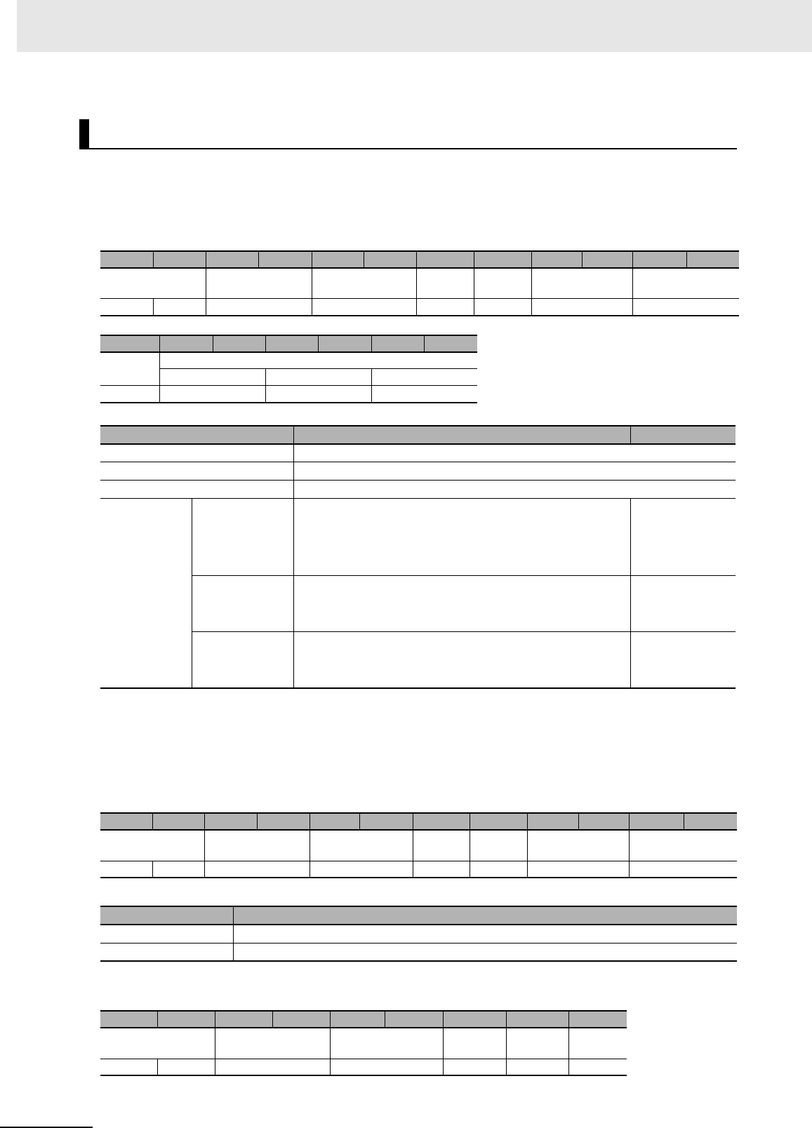
7 Modbus/TCP Communications
7 - 90 UHF RFID System V780-series Reader/Writer User’s Manual (Z389)
Function
This command sets the RSSI filter conditions for the Reader/Writer.
Command Format
Response Formats
• Normal Response
• Error Response
SET RSSI FILTER CONDITIONS
Byte-0 Byte-1 Byte-2 Byte-3 Byte-4 Byte-5 Byte-6 Byte-7 Byte-8 Byte-9 Byte-10 Byte-11
Transaction identi-
fier
Protocol identifier Field length Unit
identifier
Function
code
Register address Word count
X X 0000 hex 000D hex FF hex 10 hex C600 hex 0003 hex
Byte-12 Byte-13 Byte-14 Byte-15 Byte-16 Byte-17 Byte-18
Byte
count
RSSI filter conditions
Enable/disable High threshold Low threshold
06 hex 2 bytes 2 bytes 2 bytes
Parameter Description Default setting
Register address The register address (C600 hex) that specifies the RSSI filter conditions
Word count The number of words in the RSSI filter conditions (0003 hex)
Byte count The number of bytes in the RSSI filter conditions (06 hex)
RSSI filter
conditions
Enable/disable Specify whether the RSSI filter is enabled or disabled in
4-digits hexadecimal.
0000 hex: Disable
0001 hex: Enable
0000 hex
High threshold*1
*1. When you disable the RSSI filter conditions, set the high and low thresholds to 0000 hex. When you enable
the RSSI filter, set the high threshold value for the reception level to a higher value than the low threshold level.
Otherwise, a command parameter error will occur.
Specify the high threshold for the reception level in signed
4-digit hexadecimal.
FFF6 to FFBA hex (0 or -70 to -10) [dBm]
0000 hex
Low threshold*1 Specify the low threshold for the reception level in signed
4-digit hexadecimal.
FFF6 to FFBA hex (0 or -70 to -10) [dBm]
0000 hex
Byte-0 Byte-1 Byte-2 Byte-3 Byte-4 Byte-5 Byte-6 Byte-7 Byte-8 Byte-9 Byte-10 Byte-11
Transaction identi-
fier
Protocol identifier Field length Unit
identifier
Function
code
Register address Word count
X X 0000 hex 0006 hex FF hex 10 hex C600 hex 0003 hex
Parameter Description
Register address The register address from the command is set.
Word count The word count from the command is set.
Byte-0 Byte-1 Byte-2 Byte-3 Byte-4 Byte-5 Byte-6 Byte-7 Byte-8
Transaction identifier Protocol identifier Field length Unit iden-
tifier
Function
code
Excep-
tion code
X X 0000 hex 0003 hex FF hex 90 hex 1 byte

7 - 91
7 Modbus/TCP Communications
UHF RFID System V780-series Reader/Writer User’s Manual (Z389)
7-6 V780 Command Details
7
7-6-6 Reader/Writer Setting Commands: Communications Settings
Execution Examples
Example 1: Execution When Enabling RSSI Filter Conditions for the Reader/Writer with the Follow-
ing Settings
High threshold: -40 dBm (FFD8 hex), Low threshold: -64 dBm (FFC0 hex)
TX: 00000000000DFF10C6000003060001FFD8FFC0
RX: 000000000006FF10C6000003
Example 2: Execution When Disabling RSSI Filter Conditions for the Reader/Writer
TX: 00000000000DFF10C600000306000000000000
RX: 000000000006FF10C6000003
Parameter Description
Exception code For details, refer to Exception Code on page 7-7 under Response Format for Error
Completion on page 7-7.
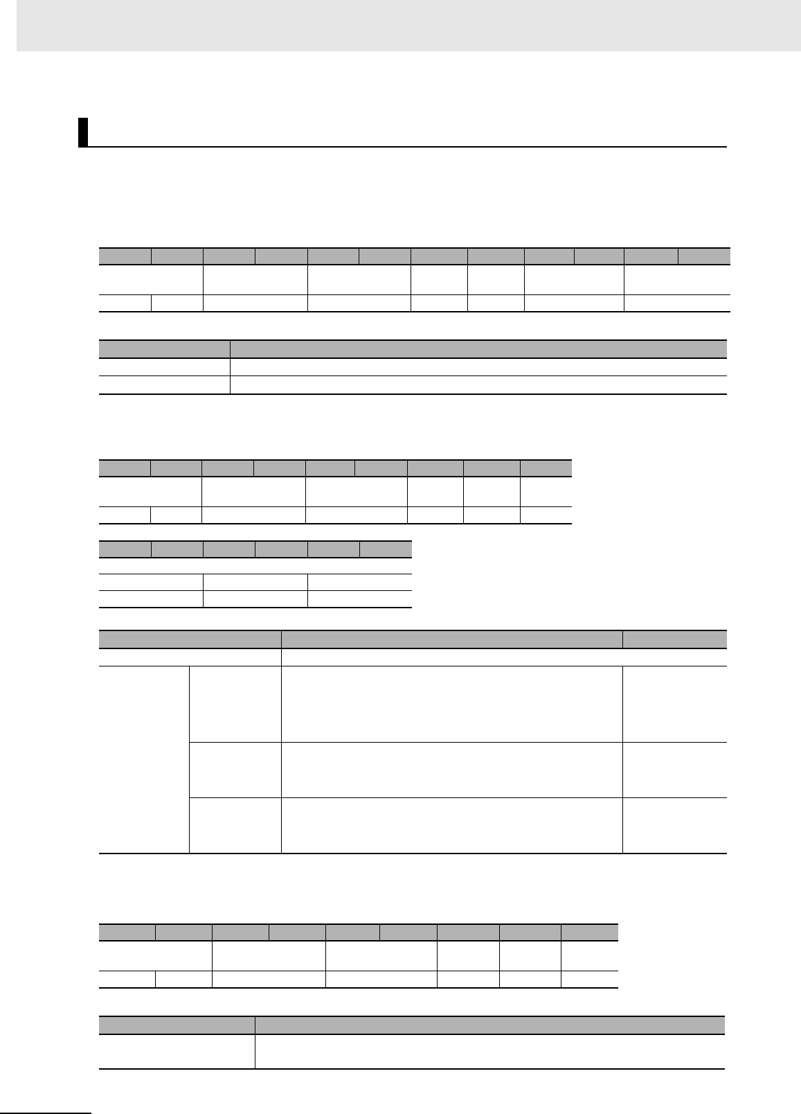
7 Modbus/TCP Communications
7 - 92 UHF RFID System V780-series Reader/Writer User’s Manual (Z389)
Function
This command is used to check the RSSI filter conditions that are set in the Reader/Writer.
Command Format
Response Formats
• Normal Response
*1. If the RSSI filter conditions are disabled, the high and low threshold levels will always be 0000 hex.
• Error Response
GET RSSI FILTER CONDITIONS
Byte-0 Byte-1 Byte-2 Byte-3 Byte-4 Byte-5 Byte-6 Byte-7 Byte-8 Byte-9 Byte-10 Byte-11
Transaction identi-
fier
Protocol identifier Field length Unit
identifier
Function
code
Register address Word count
X X 0000 hex 0006 hex FF hex 03 hex C600 hex 0003 hex
Parameter Description
Register address The register address (C600 hex) that specifies reading the RSSI filter conditions
Word count The number of words in the RSSI filter conditions to read (0003 hex)
Byte-0 Byte-1 Byte-2 Byte-3 Byte-4 Byte-5 Byte-6 Byte-7 Byte-8
Transaction identi-
fier
Protocol identifier Field length Unit
identifier
Function
code
Byte
count
X X 0000 hex 0009 hex FF hex 03 hex 04 hex
Byte-9 Byte-10 Byte-11 Byte-12 Byte-13 Byte-14
RSSI filter conditions
Enable/disable High threshold Low threshold
2 bytes 2 bytes 2 bytes
Parameter Description Default setting
Byte count The number of bytes in the RSSI filter conditions (06 hex)
RSSI filter
conditions
Enable/dis-
able
Gives whether the RSSI filter is enabled or disabled in 4-dig-
its hexadecimal.
0000 hex: Disable
0001 hex: Enable
0000 hex
High threshold
*1
Gives the RSSI high threshold level in signed 4-digit hexa-
decimal.
FFF6 to FFBA hex (0 or −70 to −10) [dBm]
0000 hex
Low threshold
*1
Gives the RSSI low threshold level in signed 4-digit hexa-
decimal.
FFF6 to FFBA hex (0 or −70 to −10) [dBm]
0000 hex
Byte-0 Byte-1 Byte-2 Byte-3 Byte-4 Byte-5 Byte-6 Byte-7 Byte-8
Transaction identifier Protocol identifier Field length Unit iden-
tifier
Function
code
Excep-
tion code
X X 0000 hex 0003 hex FF hex 83 hex 1 byte
Parameter Description
Exception code For details, refer to Exception Code on page 7-7 under 7-2-3 Response Format for
Error Completion on page 7-7.

7 - 93
7 Modbus/TCP Communications
UHF RFID System V780-series Reader/Writer User’s Manual (Z389)
7-6 V780 Command Details
7
7-6-6 Reader/Writer Setting Commands: Communications Settings
Execution Examples
Execution When RSSI Filter Conditions for the Reader/Writer Are Enabled with the Following Set-
tings
High threshold: -40 dBm (FFD8 hex), Low threshold: -64 dBm (FFC0 hex)
TX: 000000000006FF03C6000003
RX: 000000000009FF03060001FFD8FFC0
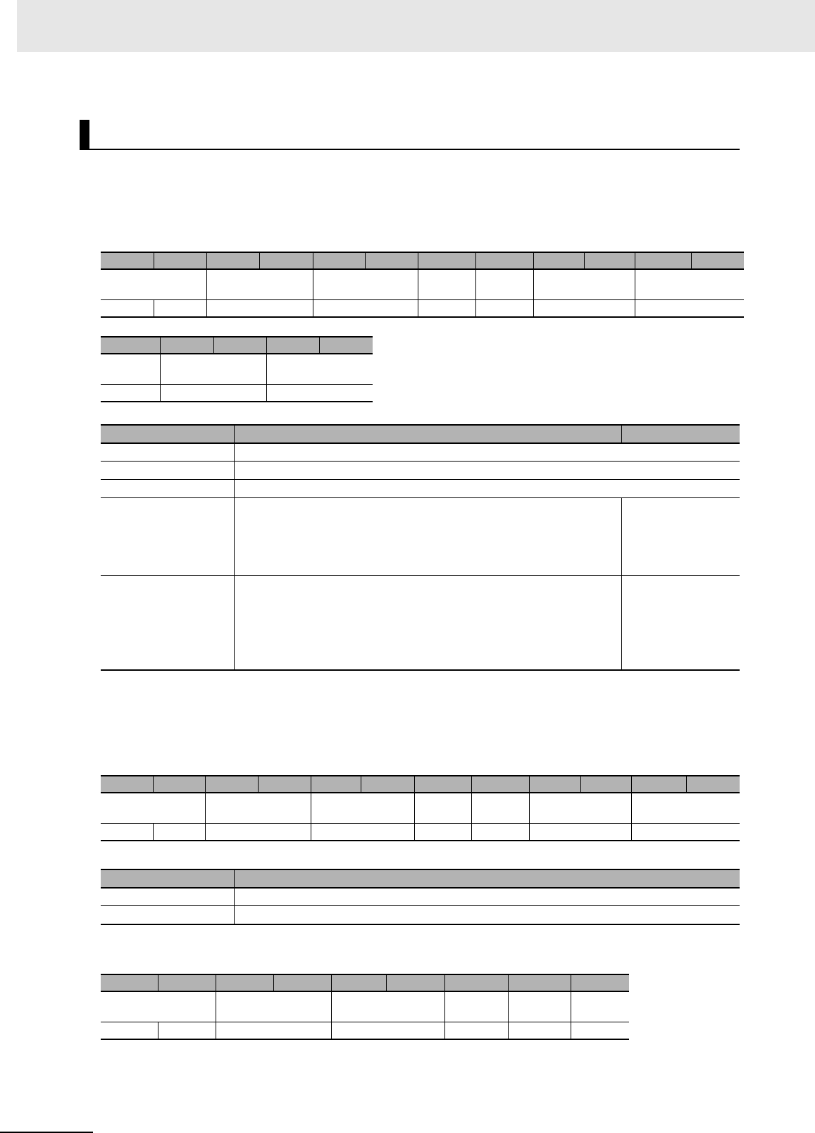
7 Modbus/TCP Communications
7 - 94 UHF RFID System V780-series Reader/Writer User’s Manual (Z389)
Function
This command sets the time to stop the transmission power.
Command Format
*1. If you set a stop time, do not set the continuous transmission time to 0000 hex (unlimited). A command
parameter error will occur if only the stop time or only the continuous transmission time is set to 0.
Response Formats
• Normal Response
• Error Response
SET TRANSMISSION TIME
Byte-0 Byte-1 Byte-2 Byte-3 Byte-4 Byte-5 Byte-6 Byte-7 Byte-8 Byte-9 Byte-10 Byte-11
Transaction identi-
fier
Protocol identifier Field length Unit
identifier
Function
code
Register address Word count
X X 0000 hex 000B hex FF hex 10 hex C700 hex 0002 hex
Byte-12 Byte-13 Byte-14 Byte-15 Byte-16
Byte
count
Stop time Continuous trans-
mission time
04 hex 2 bytes 2 bytes
Parameter Description Default setting
Register address The register address (C700 hex) that specifies setting the transmission times
Word count The number of words in the transmission time setting (0002 hex)
Byte count The number of bytes in the transmission time setting (04 hex)
Stop time
*1
Specify the time to stop the output during RF communications com-
mand execution in 4-digit hexadecimal.
0000 hex or 000A to 03E8 hex
(0000 hex = None, or 10 to 1,000) [ms]
0000 hex
Continuous transmis-
sion time
*1
Specify the maximum time to continuously output radio waves
during RF communications command execution in 4-digit hexadeci-
mal.
0000 hex or 0190 to 2710 hex
(0000 hex = Unlimited, or 400 to 10,000) [ms]
0000 hex
Byte-0 Byte-1 Byte-2 Byte-3 Byte-4 Byte-5 Byte-6 Byte-7 Byte-8 Byte-9 Byte-10 Byte-11
Transaction identi-
fier
Protocol identifier Field length Unit
identifier
Function
code
Register address Word count
X X 0000 hex 0006 hex FF hex 10 hex C700 hex 0002 hex
Parameter Description
Register address The register address from the command is set.
Word count The word count from the command is set.
Byte-0 Byte-1 Byte-2 Byte-3 Byte-4 Byte-5 Byte-6 Byte-7 Byte-8
Transaction identifier Protocol identifier Field length Unit iden-
tifier
Function
code
Excep-
tion code
X X 0000 hex 0003 hex FF hex 90 hex 1 byte

7 - 95
7 Modbus/TCP Communications
UHF RFID System V780-series Reader/Writer User’s Manual (Z389)
7-6 V780 Command Details
7
7-6-6 Reader/Writer Setting Commands: Communications Settings
Execution Examples
Example 1: Execution to Set the Following Times in the Reader/Writer
Stop time: 10 ms (000A hex), Continuous transmission time: 400 ms (0190 hex)
TX: 00000000000BFF10C700000204000A0190
RX: 000000000006FF10C7000002
Example 2: Execution to Set the Following Times in the Reader/Writer
Stop time: None, Continuous transmission time: Unlimited
TX: 00000000000BFF10C70000020400000000
RX: 000000000006FF10C7000002
Parameter Description
Exception code For details, refer to Exception Code on page 7-7 under 7-2-3 Response Format for
Error Completion on page 7-7.
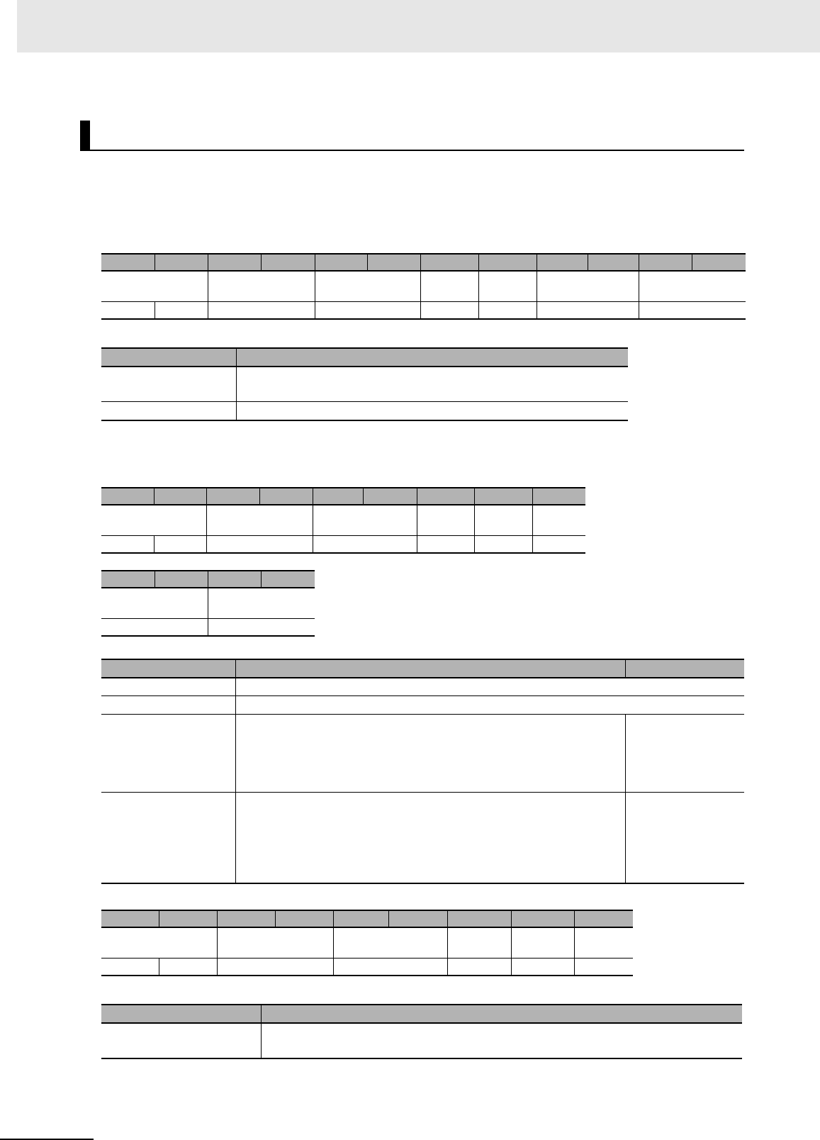
7 Modbus/TCP Communications
7 - 96 UHF RFID System V780-series Reader/Writer User’s Manual (Z389)
Function
This command is used to check the transmission times that are set in the Reader/Writer.
Command Format
Response Formats
• Normal Response
• Error Response
GET TRANSMISSION TIME
Byte-0 Byte-1 Byte-2 Byte-3 Byte-4 Byte-5 Byte-6 Byte-7 Byte-8 Byte-9 Byte-10 Byte-11
Transaction identi-
fier
Protocol identifier Field length Unit
identifier
Function
code
Register address Word count
X X 0000 hex 0006 hex FF hex 03 hex C700 hex 0002 hex
Parameter Description
Register address The register address (C700 hex) that specifies reading the trans-
mission time settings
Word count Always 0002 hex.
Byte-0 Byte-1 Byte-2 Byte-3 Byte-4 Byte-5 Byte-6 Byte-7 Byte-8
Transaction identi-
fier
Protocol identifier Field length Unit
identifier
Function
code
Byte
count
X X 0000 hex 0007 hex FF hex 03 hex 04 hex
Byte-9 Byte-10 Byte-11 Byte-12
Stop time Continuous trans-
mission time
2 bytes 2 bytes
Parameter Description Default setting
Field length Always 0007 hex.
Byte count The number of bytes in the transmission times to read (04 hex)
Stop time Gives the time that is set to stop the output during RF communica-
tions command execution in 4-digit hexadecimal.
0000 hex or 000A to 03E8 hex
(0000 hex = None, or 10 to 1,000) [ms]
0000 hex
Continuous transmis-
sion time
Gives the maximum time that is set to continuously output radio
waves during RF communications command execution in 4-digit
hexadecimal.
0000 hex, 0190 to 2710 hex (0000 hex: Unlimited, or 400 to 10,000)
[ms]
0000 hex
Byte-0 Byte-1 Byte-2 Byte-3 Byte-4 Byte-5 Byte-6 Byte-7 Byte-8
Transaction identifier Protocol identifier Field length Unit iden-
tifier
Function
code
Excep-
tion code
X X 0000 hex 0003 hex FF hex 83 hex 1 byte
Parameter Description
Exception code For details, refer to Exception Code on page 7-7 under 7-2-3 Response Format for
Error Completion on page 7-7.

7 - 97
7 Modbus/TCP Communications
UHF RFID System V780-series Reader/Writer User’s Manual (Z389)
7-6 V780 Command Details
7
7-6-6 Reader/Writer Setting Commands: Communications Settings
Execution Examples
Execution When the Following RF Transmission Times Are Set in the Reader/Writer
Stop time: 10 ms (000A hex), Continuous transmission time: 400 ms (0190 hex)
TX: 000000000006FF03C7000002
RX: 000000000007FF0304000A0190
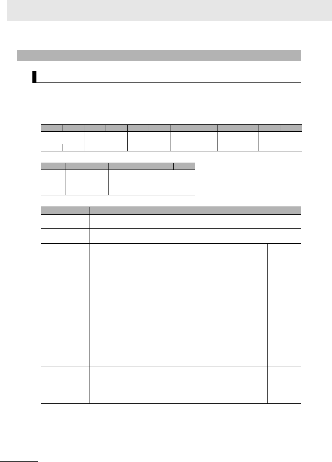
7 Modbus/TCP Communications
7 - 98 UHF RFID System V780-series Reader/Writer User’s Manual (Z389)
Function
This command sets the colors of the NORM/ERR indicators during command execution.
Command Format
*1. To prevent the NORM/ERR indicators from lighting at all during command execution, set all of the lighting
conditions to “Do not flash.” You cannot prevent them from lighting by setting only individual conditions.
7-6-7 Reader/Writer Setting Commands: Device Settings
SET OPERATION INDICATOR CUSTOM CONDITIONS
Byte-0 Byte-1 Byte-2 Byte-3 Byte-4 Byte-5 Byte-6 Byte-7 Byte-8 Byte-9 Byte-10 Byte-11
Transaction identi-
fier
Protocol identifier Field length Unit
identifier
Function
code
Register address Word count
X X 0000 hex 000D hex FF hex 10 hex B800 hex 0003 hex
Byte-12 Byte-13 Byte-14 Byte-15 Byte-16 Byte-17 Byte-18
Byte
count
Color to flash once
for normal com-
mand execution
Color to flash once
for command error
Color to flash once
for unstable com-
munications
06 hex 2 bytes 2 bytes 2 bytes
Parameter Description
Register address The register address (B800 hex) that specifies setting operation indicator custom condi-
tions
Word count The number of words in the operation indicator custom condition settings (0003 hex)
Byte count The number of bytes in the operation indicator custom condition settings (06 hex)
Color to flash once
for normal com-
mand execution
Specify the color to flash once when V780 command processing ends nor-
mally in 4-digit hexadecimal.
0000 hex: Default
0001 hex: Green
0002 hex: Red
0003 hex: Yellow
0004 hex: Blue
0005 hex: Cyan
0006 hex: Magenta
0007 hex: White
FFFF hex: Do not flash.*1
0000 hex
Color to flash once
for command error
Specify the color to flash once when V780 command processing ends in an
error in 4-digit hexadecimal.
*The color settings are they same as for flashing once for normal command
completion, given above.
0002 hex
Color to flash once
for unstable com-
munications
Specify the color to flash once when the results of executing communica-
tions diagnostics indicates that communications are unstable in 4-digit hexa-
decimal.
*The colors settings are they same as for flashing once for normal command
completion, given above.
0003 hex
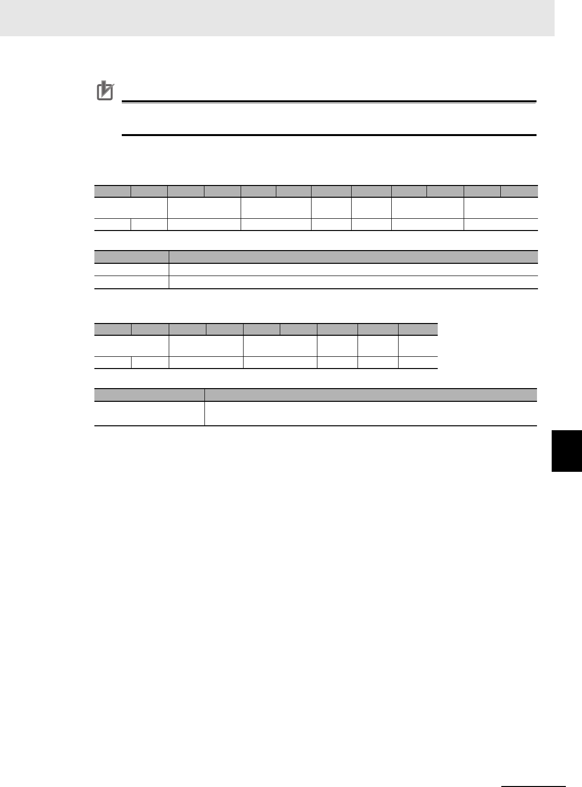
7 - 99
7 Modbus/TCP Communications
UHF RFID System V780-series Reader/Writer User’s Manual (Z389)
7-6 V780 Command Details
7
7-6-7 Reader/Writer Setting Commands: Device Settings
Precautions for Correct Use
If you set all of the conditions to “Do not flash,” the NORM/ERR indicators will not light at all
even during operation in Focus Mode.
Response Formats
• Normal Response
• Error Response
Execution Examples
Execution to Set Operation Indicator Custom Conditions for the Reader/Writer
Example 1: Execution to Change to the Following Colors for the NORM/ERR Indicators during Com-
mand Execution
Normal completion: Cyan, Error completion: Magenta, Unstable communications: White
TX: 00000000000DFF10B800000306000500060007
RX: 000000000006FF10B8000003
Example 2: Execution to Change the NORM/ERR Indicators to Not Light at All during Command
Execution
TX: 00000000000DFF10B800000306FFFFFFFFFFFF
RX: 000000000006FF10B8000003
Byte-0 Byte-1 Byte-2 Byte-3 Byte-4 Byte-5 Byte-6 Byte-7 Byte-8 Byte-9 Byte-10 Byte-11
Transaction identi-
fier
Protocol identifier Field length Unit
identifier
Function
code
Register address Word count
X X 0000 hex 0006 hex FF hex 10 hex B800 hex 0003 hex
Parameter Description
Register address The register address from the command is set.
Word count The word count from the command is set.
Byte-0 Byte-1 Byte-2 Byte-3 Byte-4 Byte-5 Byte-6 Byte-7 Byte-8
Transaction identi-
fier
Protocol identifier Field length Unit
identifier
Function
code
Excep-
tion code
X X 0000 hex 0003 hex FF hex 90 hex 1 byte
Parameter Description
Exception code For details, refer to Exception Code on page 7-7 under 7-2-3 Response Format for
Error Completion on page 7-7.
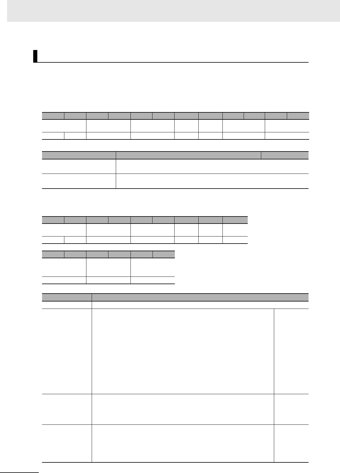
7 Modbus/TCP Communications
7 - 100 UHF RFID System V780-series Reader/Writer User’s Manual (Z389)
Function
This command is used to check the NORM/ERR indicator lighting colors for communications results
that are set in the Reader/Writer.
Command Format
Response Formats
• Normal Response
GET OPERATION INDICATOR CUSTOM CONDITIONS
Byte-0 Byte-1 Byte-2 Byte-3 Byte-4 Byte-5 Byte-6 Byte-7 Byte-8 Byte-9 Byte-10 Byte-11
Transaction identi-
fier
Protocol identifier Field length Unit
identifier
Function
code
Register address Word count
X X 0000 hex 0006 hex FF hex 03 hex B800 hex 0003 hex
Parameter Description Default setting
Register address The register address (B800 hex) that specifies the operation indicator custom
settings
Word count The number of words in the operation indicator custom conditions to read (0003
hex)
Byte-0 Byte-1 Byte-2 Byte-3 Byte-4 Byte-5 Byte-6 Byte-7 Byte-8
Transaction identi-
fier
Protocol identifier Field length Unit
identifier
Function
code
Byte
count
X X 0000 hex 0009 hex FF hex 03 hex 06 hex
Byte-9 Byte-10 Byte-11 Byte-12 Byte-13 Byte-14
Color to flash once
for normal com-
mand execution
Color to flash once
for command error
Color to flash once
for unstable com-
munications
2 bytes 2 bytes 2 bytes
Parameter Description
Byte count The number of bytes in the operation indicator custom settings (06 hex)
Color to flash once
for normal com-
mand execution
Gives the color to flash once when V780 command processing ends nor-
mally in 4-digit hexadecimal.
0001 hex: Green
0002 hex: Red
0003 hex: Yellow
0004 hex: Blue
0004 hex: Blue
0006 hex: Magenta
0007 hex: White
FFFF hex: Do not flash.
0001 hex
Color to flash once
for command error
Gives the color to flash once when V780 command processing ends in an
error in 4-digit hexadecimal.
*The colors settings are they same as for flashing once for normal command
completion, given above.
0002 hex
Color to flash once
for unstable com-
munications
Gives the color to flash once when the results of executing communications
diagnostics indicates that communications are unstable in 4-digit hexadeci-
mal.
*The colors settings are they same as for flashing once for normal command
completion, given above.
0003 hex

7 - 101
7 Modbus/TCP Communications
UHF RFID System V780-series Reader/Writer User’s Manual (Z389)
7-6 V780 Command Details
7
7-6-7 Reader/Writer Setting Commands: Device Settings
• Error Response
Execution Examples
Execution When the Following NORM/ERR Indicator Lighting Colors Are Set for Command Execu-
tion by the Reader/Writer
Normal completion: Green, Error completion: Red, Unstable communications: Yellow
TX: 000000000006FF03B8000003
RX: 000000000009FF0306000100020003
Byte-0 Byte-1 Byte-2 Byte-3 Byte-4 Byte-5 Byte-6 Byte-7 Byte-8
Transaction identi-
fier
Protocol identifier Field length Unit
identifier
Function
code
Excep-
tion code
X X 0000 hex 0003 hex FF hex 83 hex 1 byte
Parameter Description
Exception code For details, refer to Exception Code on page 7-7 under 7-2-3 Response Format for
Error Completion on page 7-7.
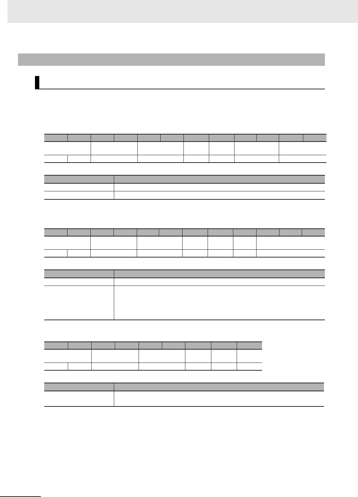
7 Modbus/TCP Communications
7 - 102 UHF RFID System V780-series Reader/Writer User’s Manual (Z389)
Function
This command is used to check the model number of the Reader/Writer.
Command Format
Response Formats
• Normal Response
• Error Response
7-6-8 Maintenance Commands: Device Information
GET MODEL INFORMATION
Byte-0 Byte-1 Byte-2 Byte-3 Byte-4 Byte-5 Byte-6 Byte-7 Byte-8 Byte-9 Byte-10 Byte-11
Transaction identi-
fier
Protocol identifier Field length Unit
identifier
Function
code
Register address Word count
X X 0000 hex 0006 hex FF hex 03 hex D000 hex 0010 hex
Parameter Description
Register address The register address (D000 hex) that specifies the model number information
Word count The number of words in the model number information to read (0010 hex)
Byte-0 Byte-1 Byte-2 Byte-3 Byte-4 Byte-5 Byte-6 Byte-7 Byte-8 Byte-9 ... Byte-40
Transaction identi-
fier
Protocol identifier Field length Unit
identifier
Function
code
Byte
count
Model information
X X 0000 hex 0023 hex FF hex 03 hex 20 hex 32 bytes
Parameter Description
Byte count The number of bytes in the model number information that was read (20 hex)
Model information Gives the model information that was read with up to 32 bytes of ASCII characters
(up to 31 ASCII characters plus the end code (00 hex)).
If there are fewer than 31 characters, the remaining bytes are filled with 00 hex.
The model number is given with ASCII characters 20 hex (space) to 7E hex (~).
Byte-0 Byte-1 Byte-2 Byte-3 Byte-4 Byte-5 Byte-6 Byte-7 Byte-8
Transaction identi-
fier
Protocol identifier Field length Unit
identifier
Function
code
Excep-
tion code
X X 0000 hex 0003 hex FF hex 83 hex 1 byte
Parameter Description
Exception code For details, refer to Exception Code on page 7-7 under 7-2-3 Response Format for
Error Completion on page 7-7.

7 - 103
7 Modbus/TCP Communications
UHF RFID System V780-series Reader/Writer User’s Manual (Z389)
7-6 V780 Command Details
7
7-6-8 Maintenance Commands: Device Information
Execution Examples
Execution to Read the Model Number When a V780-HMD68-ETN Reader/Writer Is Being Used
TX: 000000000006FF03D0000010
RX:
000000000023FF0320563738302D484D4436382D45544E0000000000000000000000000000000
00000
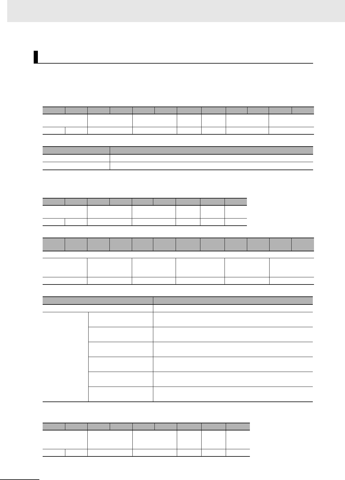
7 Modbus/TCP Communications
7 - 104 UHF RFID System V780-series Reader/Writer User’s Manual (Z389)
Function
This command reads the firmware version of the Reader/Writer.
Command Format
Response Formats
• Normal Response
• Error Response
GET FIRMWARE VERSION
Byte-0 Byte-1 Byte-2 Byte-3 Byte-4 Byte-5 Byte-6 Byte-7 Byte-8 Byte-9 Byte-10 Byte-11
Transaction identi-
fier
Protocol identifier Field length Unit
identifier
Function
code
Register address Word count
X X 0000 hex 0006 hex FF hex 03 hex D100 hex 0006 hex
Parameter Description
Register address The register address (D100 hex) that specifies the firmware version
Word count The number of words in the firmware version information to read (0006 hex)
Byte-0 Byte-1 Byte-2 Byte-3 Byte-4 Byte-5 Byte-6 Byte-7 Byte-8
Transaction identi-
fier
Protocol identifier Field length Unit
identifier
Function
code
Byte
count
X X 0000 hex 000F hex FF hex 03 hex 0C hex
Byte-9 Byte-10 Byte-11 Byte-12 Byte-1
3Byte-14 Byte-15 Byte-16 Byte-17 Byte-18 Byte-19 Byte-20
Firmware version
Major version of
Run Mode pro-
gram
Minor version of
Run Mode pro-
gram
Run Mode pro-
gram revision
Major version of
Safe Mode program
Minor version of
Safe Mode pro-
gram
Safe Mode pro-
gram revision
2 bytes 2 bytes 2 bytes 2 bytes 2 bytes 2 bytes
Parameter Description
Byte count The number of bytes in the firmware version information (0C hex)
Firmware version Major version of Run
Mode program
0000 to 0099 hex (BCD)
Minor version of Run
Mode program
0000 to 0099 hex (BCD)
Run Mode program revi-
sion
0000 to 9999 hex (BCD)
Major version of Safe
Mode program
0000 to 0099 hex (BCD)
Minor version of Safe
Mode program
0000 to 0099 hex (BCD)
Safe Mode program revi-
sion
0000 to 9999 hex (BCD)
Byte-0 Byte-1 Byte-2 Byte-3 Byte-4 Byte-5 Byte-6 Byte-7 Byte-8
Transaction identi-
fier
Protocol identifier Field length Unit
identifier
Function
code
Excep-
tion
code
X X 0000 hex 0003 hex FF hex 83 hex 1 byte

7 - 105
7 Modbus/TCP Communications
UHF RFID System V780-series Reader/Writer User’s Manual (Z389)
7-6 V780 Command Details
7
7-6-8 Maintenance Commands: Device Information
Execution Examples
Execution with the Following Firmware Versions in the Reader/Writer
Run Mode program version: 1.2.3, Safe Mode program version: 1.2.2
TX: 000000000006FF03D1000006
RX: 00000000000FFF030C000100020003000100020002
Parameter Description
Exception code For details, refer to Exception Code on page 7-7 under 7-2-3 Response Format for
Error Completion on page 7-7.
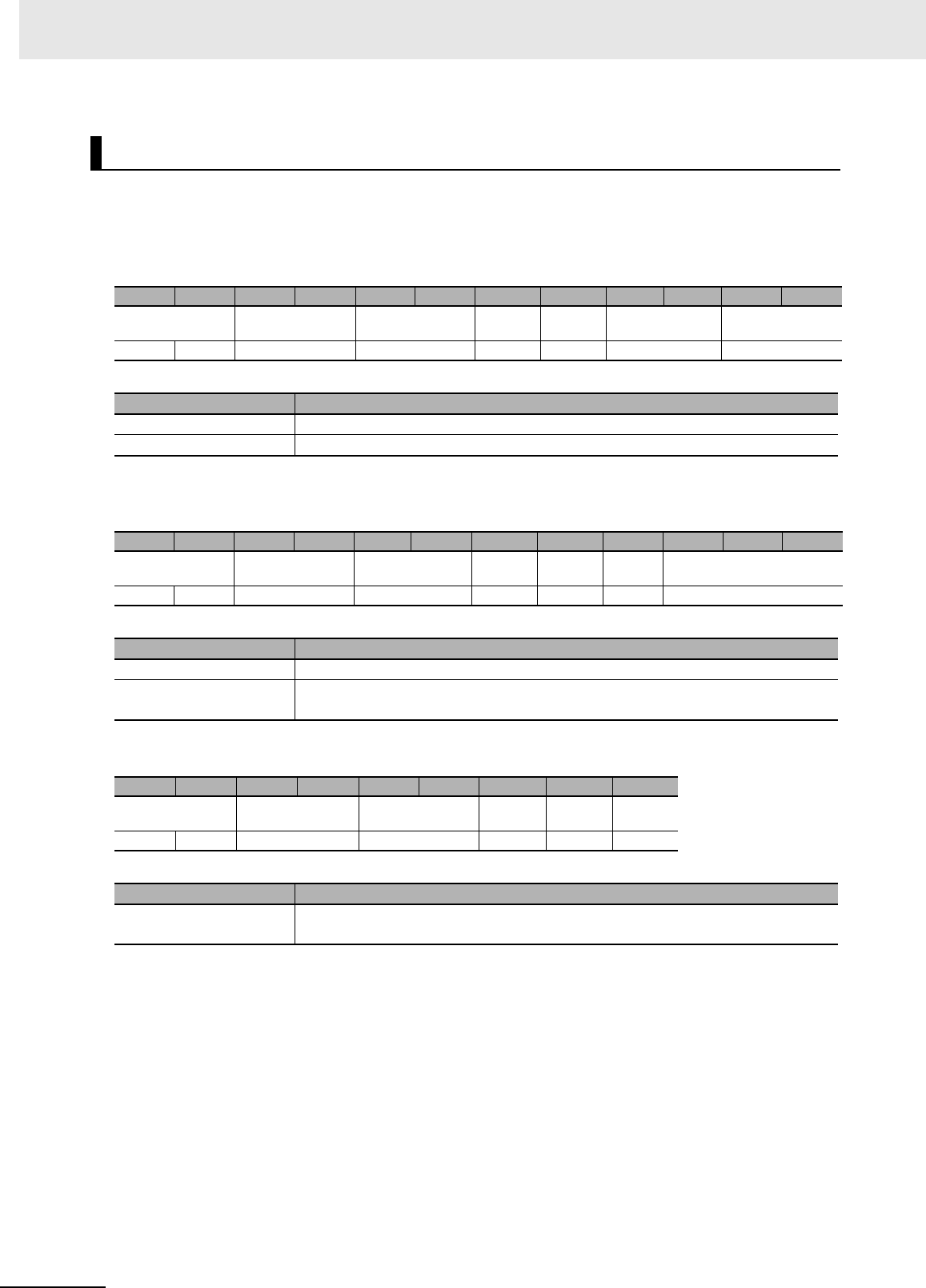
7 Modbus/TCP Communications
7 - 106 UHF RFID System V780-series Reader/Writer User’s Manual (Z389)
Function
This command is used to check the MAC address from the Reader/Writer.
Command Format
Response Formats
• Normal Response
• Error Response
Execution Examples
Execution to Read a MAC Address of “11-22-33-44-55-66” from the Reader/Writer
TX: 000000000006FF03D2000003
RX: 000000000009FF0306112233445566
GET MAC ADDRESS
Byte-0 Byte-1 Byte-2 Byte-3 Byte-4 Byte-5 Byte-6 Byte-7 Byte-8 Byte-9 Byte-10 Byte-11
Transaction identi-
fier
Protocol identifier Field length Unit
identifier
Function
code
Register address Word count
X X 0000 hex 0006 hex FF hex 03 hex D200 hex 0003 hex
Parameter Description
Register address The register address (D200 hex) that specifies the MAC address
Word count The number of words in the MAC address to read (0003 hex)
Byte-0 Byte-1 Byte-2 Byte-3 Byte-4 Byte-5 Byte-6 Byte-7 Byte-8 Byte-9 ... Byte-14
Transaction identi-
fier
Protocol identifier Field length Unit
identifier
Function
code
Byte
count
MAC address
X X 0000 hex 0009 hex FF hex 03 hex 06 hex 6 bytes
Parameter Description
Byte count The number of bytes in the MAC address that was read (06 hex)
MAC address Gives the MAC address that was read as a 12-digit hexadecimal between
000000000000 and FFFFFFFFFFFF hex.
Byte-0 Byte-1 Byte-2 Byte-3 Byte-4 Byte-5 Byte-6 Byte-7 Byte-8
Transaction identi-
fier
Protocol identifier Field length Unit
identifier
Function
code
Excep-
tion code
X X 0000 hex 0003 hex FF hex 83 hex 1 byte
Parameter Description
Exception code For details, refer to Exception Code on page 7-7 under 7-2-3 Response Format for
Error Completion on page 7-7.
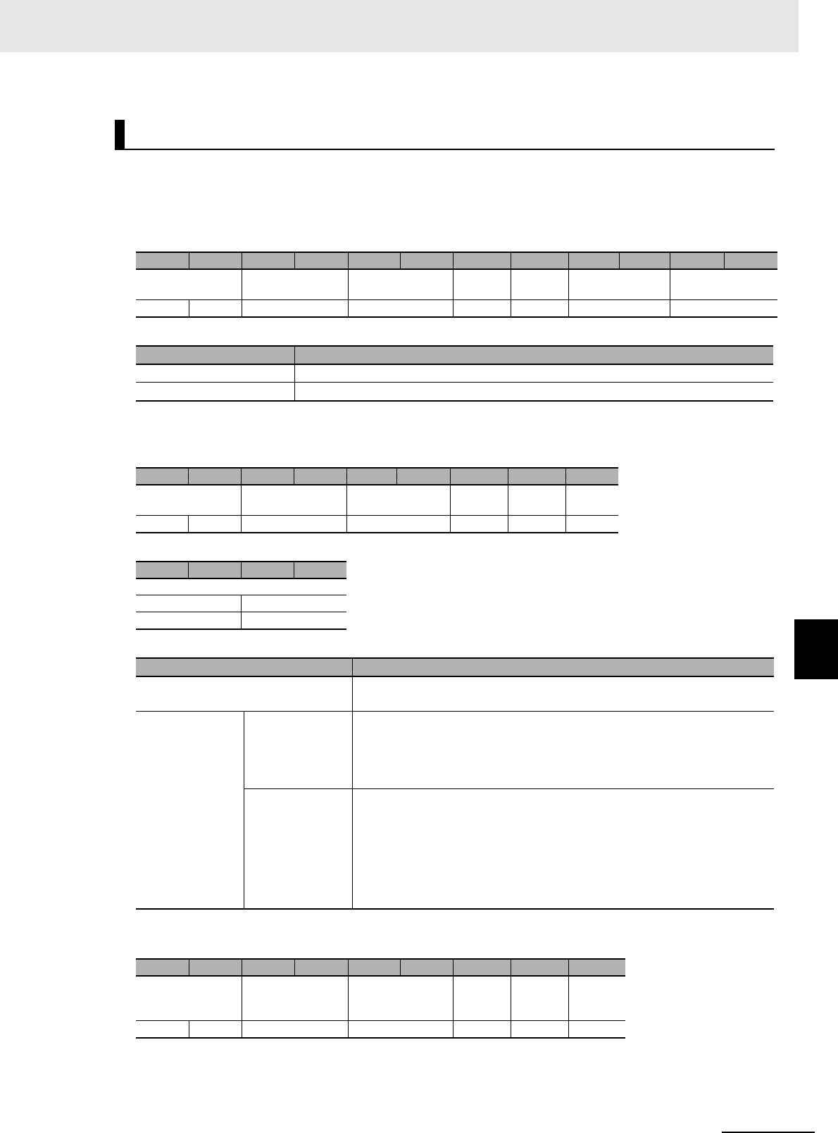
7 - 107
7 Modbus/TCP Communications
UHF RFID System V780-series Reader/Writer User’s Manual (Z389)
7-6 V780 Command Details
7
7-6-8 Maintenance Commands: Device Information
Function
This command is used to check the operating status from the Reader/Writer.
Command Format
Response Formats
• Normal Response
• Error Response
GET OPERATING STATUS
Byte-0 Byte-1 Byte-2 Byte-3 Byte-4 Byte-5 Byte-6 Byte-7 Byte-8 Byte-9 Byte-10 Byte-11
Transaction identi-
fier
Protocol identifier Field length Unit
identifier
Function
code
Register address Word count
X X 0000 hex 0006 hex FF hex 03 hex D300 hex 0002 hex
Parameter Description
Register address The register address (D300 hex) that specifies the operating status
Word count The number of words in the Reader/Writer operating status to read (0002 hex)
Byte-0 Byte-1 Byte-2 Byte-3 Byte-4 Byte-5 Byte-6 Byte-7 Byte-8
Transaction identi-
fier
Protocol identifier Field length Unit
identifier
Function
code
Byte
count
X X 0000 hex 0007 hex FF hex 03 hex 04 hex
Byte-9 Byte-10 Byte-11 Byte-12
Reader/Writer operating status
Mode Status
2 bytes 2 bytes
Parameter Description
Byte count The number of bytes in the Reader/Writer operating status that was read
(0C hex)
Reader/Writer
operating status
Mode Gives the mode of the Reader/Writer that was read in 4-digits hexadeci-
mal.
0000 hex: Safe Mode
0001 hex: Run Mode
Status Gives the status of the Reader/Writer that was read in 4-digits hexadeci-
mal.
0001 hex: Idling
0002 hex: RF Tag communications in progress
0003 hex: Changing settings
0004 hex: Error
Byte-0 Byte-1 Byte-2 Byte-3 Byte-4 Byte-5 Byte-6 Byte-7 Byte-8
Transaction identi-
fier
Protocol identifier Field length Unit
identifier
Function
code
Excep-
tion
code
X X 0000 hex 0003 hex FF hex 83 hex 1 byte

7 Modbus/TCP Communications
7 - 108 UHF RFID System V780-series Reader/Writer User’s Manual (Z389)
Execution Examples
Execution with the Following Reader/Writer Operating Status
Mode: Run Mode, Status: Idling
TX: 000000000006FF03D3000002
RX: 000000000007FF030400010001
Parameter Description
Exception code For details, refer to Exception Code on page 7-7 under 7-2-3 Response Format for
Error Completion on page 7-7.
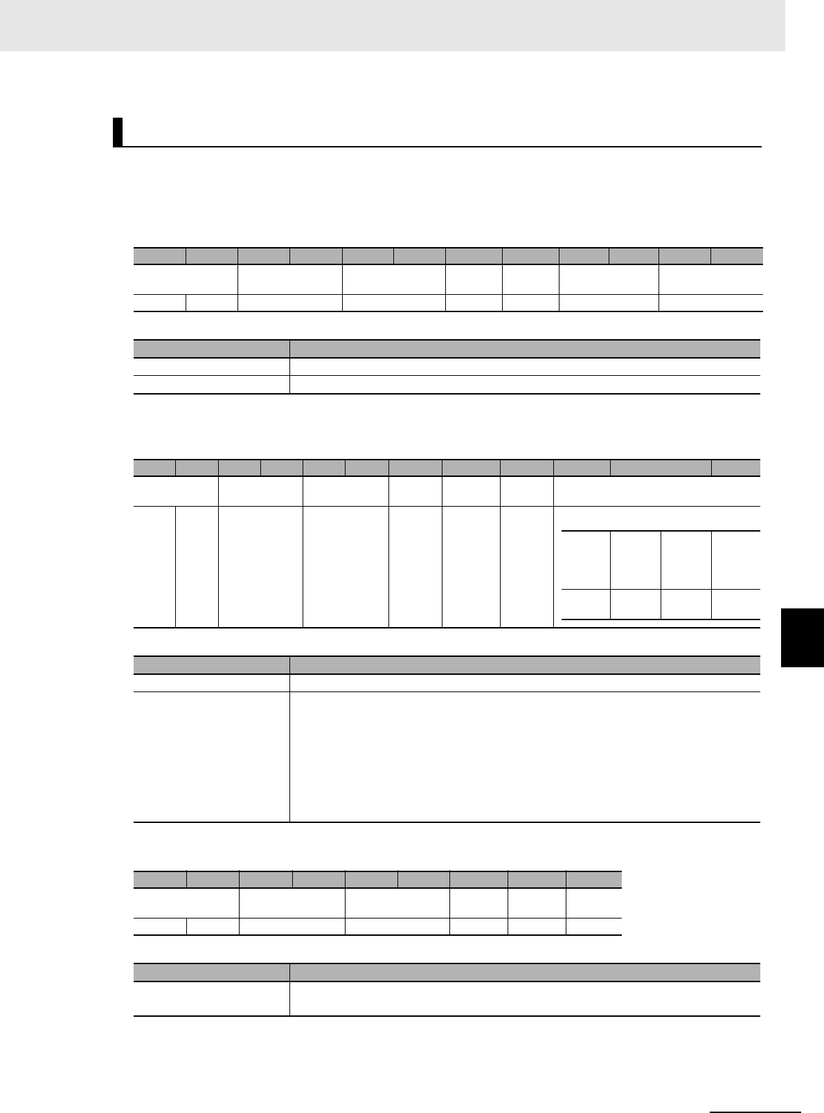
7 - 109
7 Modbus/TCP Communications
UHF RFID System V780-series Reader/Writer User’s Manual (Z389)
7-6 V780 Command Details
7
7-6-8 Maintenance Commands: Device Information
Function
This command is used to check the time information from the Reader/Writer.
Command Format
Response Formats
• Normal Response
• Error Response
GET TIME INFORMATION
Byte-0 Byte-1 Byte-2 Byte-3 Byte-4 Byte-5 Byte-6 Byte-7 Byte-8 Byte-9 Byte-10 Byte-11
Transaction identi-
fier
Protocol identifier Field length Unit
identifier
Function
code
Register address Word count
X X 0000 hex 0006 hex FF hex 03 hex D400 hex 0002 hex
Parameter Description
Register address The register address (D400 hex) that specifies the time information
Word count The number of words in the time information to read (0002 hex)
Byte-0 Byte-1 Byte-2 Byte-3 Byte-4 Byte-5 Byte-6 Byte-7 Byte-8 Byte-9 ... Byte-12
Transaction
identifier
Protocol identi-
fier
Field length Unit
identifier
Function
code
Byte
count
Time information
X X 0000 hex 0007 hex FF hex 03 hex 04 hex 4 bytes
Actual
time
flag:*1
0/1
Hour: 0
to 23
Minutes:
0 to 59
Sec-
onds: 0
to 59
1
byte
1
byte
1
byte
1
byte
Parameter Description
Byte count The number of bytes in the time information that was read (04 hex)
Time information Gives the time information that is managed inside the Reader/Writer in 4-digit hexa-
decimal.
*1 This byte indicates whether the actual time was set from the host device.
0: The time has not been set, so the time information gives the running time since
the power supply to the Reader/Writer was turned ON.
1: The time was set, so the time information is the running time from the time set
from the host device.
Byte-0 Byte-1 Byte-2 Byte-3 Byte-4 Byte-5 Byte-6 Byte-7 Byte-8
Transaction identi-
fier
Protocol identifier Field length Unit
identifier
Function
code
Excep-
tion code
X X 0000 hex 0003 hex FF hex 83 hex 1 byte
Parameter Description
Exception code For details, refer to Exception Code on page 7-7 under 7-2-3 Response Format for
Error Completion on page 7-7.

7 Modbus/TCP Communications
7 - 110 UHF RFID System V780-series Reader/Writer User’s Manual (Z389)
Execution Examples
Execution When the Time Information in the Reader/Writer Is 09:30:10
TX: 000000000006FF03D4000002
RX: 000000000007FF030400091E0A
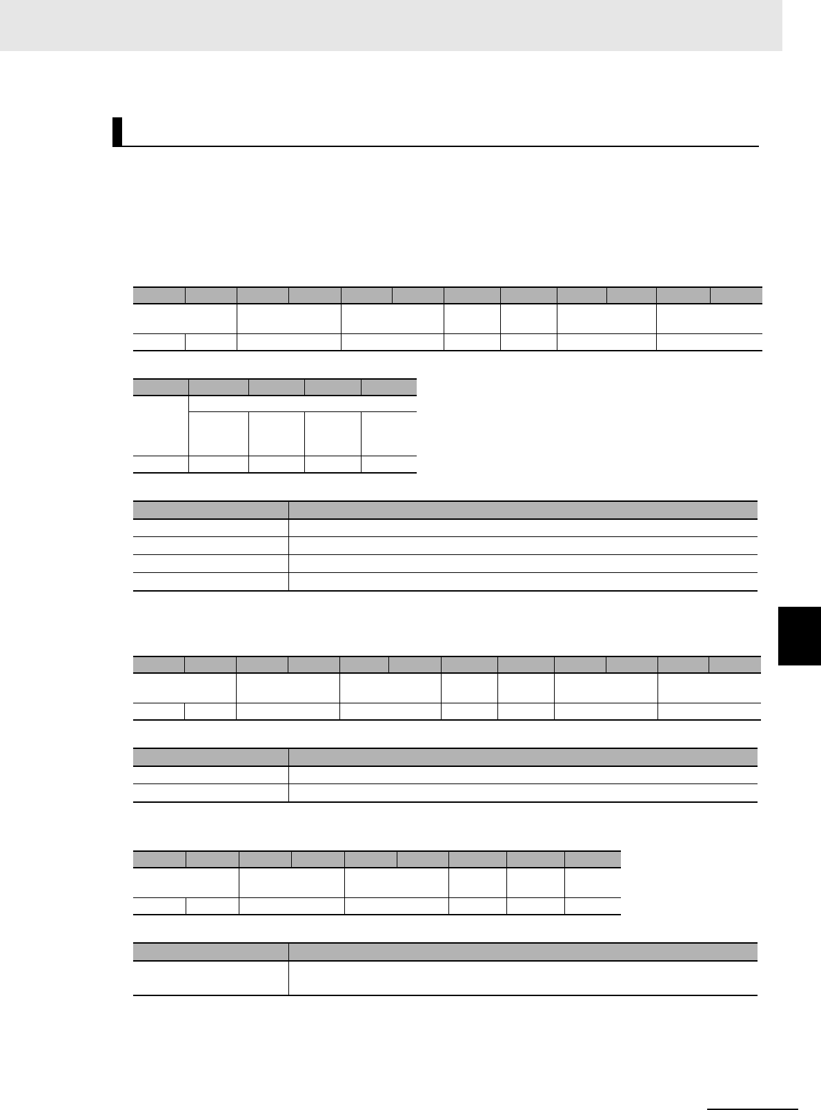
7 - 111
7 Modbus/TCP Communications
UHF RFID System V780-series Reader/Writer User’s Manual (Z389)
7-6 V780 Command Details
7
7-6-8 Maintenance Commands: Device Information
Function
This command sets the time information in the Reader/Writer.
When the Reader/Writer is restarted, the time information is reset. (All zeros will be set for the actual
time flag, hour, minutes, and seconds.)
Command Format
Response Formats
• Normal Response
• Error Response
SET TIME INFORMATION
Byte-0 Byte-1 Byte-2 Byte-3 Byte-4 Byte-5 Byte-6 Byte-7 Byte-8 Byte-9 Byte-10 Byte-11
Command Format Protocol identifier Field length Unit
identifier
Function
code
Register address Word count
X X 0000 hex 000B hex FF hex 10 hex D400 hex 0002 hex
Byte-12 Byte-13 Byte-14 Byte-15 Byte-16
Byte
count
Time information
Reserved Hour: 0
to 23
Minutes:
0 to 59
Sec-
onds: 0
to 59
04 hex 1 byte 1 byte 1 byte 1 byte
Parameter Description
Register address The register address (D400 hex) that specifies the time information
Word count The number of words of time information (0002 hex)
Byte count The number of bytes of time information (04 hex)
Time information The time to set in the Reader/Writer in 8-digit hexadecimal.
Byte-0 Byte-1 Byte-2 Byte-3 Byte-4 Byte-5 Byte-6 Byte-7 Byte-8 Byte-9 Byte-10 Byte-11
Transaction identi-
fier
Protocol identifier Field length Unit
identifier
Function
code
Register address Word count
X X 0000 hex 0006 hex FF hex 10 hex D400 hex 0002 hex
Parameter Description
Register address The register address from the command is set.
Word count The word count from the command is set.
Byte-0 Byte-1 Byte-2 Byte-3 Byte-4 Byte-5 Byte-6 Byte-7 Byte-8
Transaction identi-
fier
Protocol identifier Field length Unit
identifier
Function
code
Excep-
tion code
X X 0000 hex 0003 hex FF hex 90 hex 1 byte
Parameter Description
Exception code For details, refer to Exception Code on page 7-7 under 7-2-3 Response Format for
Error Completion on page 7-7.

7 Modbus/TCP Communications
7 - 112 UHF RFID System V780-series Reader/Writer User’s Manual (Z389)
Execution Examples
Execution to Set the Time Information in the Reader/Writer to 09:30:10
TX: 00000000000BFF10D40000020400091E0A
RX: 000000000006FF10D4000002
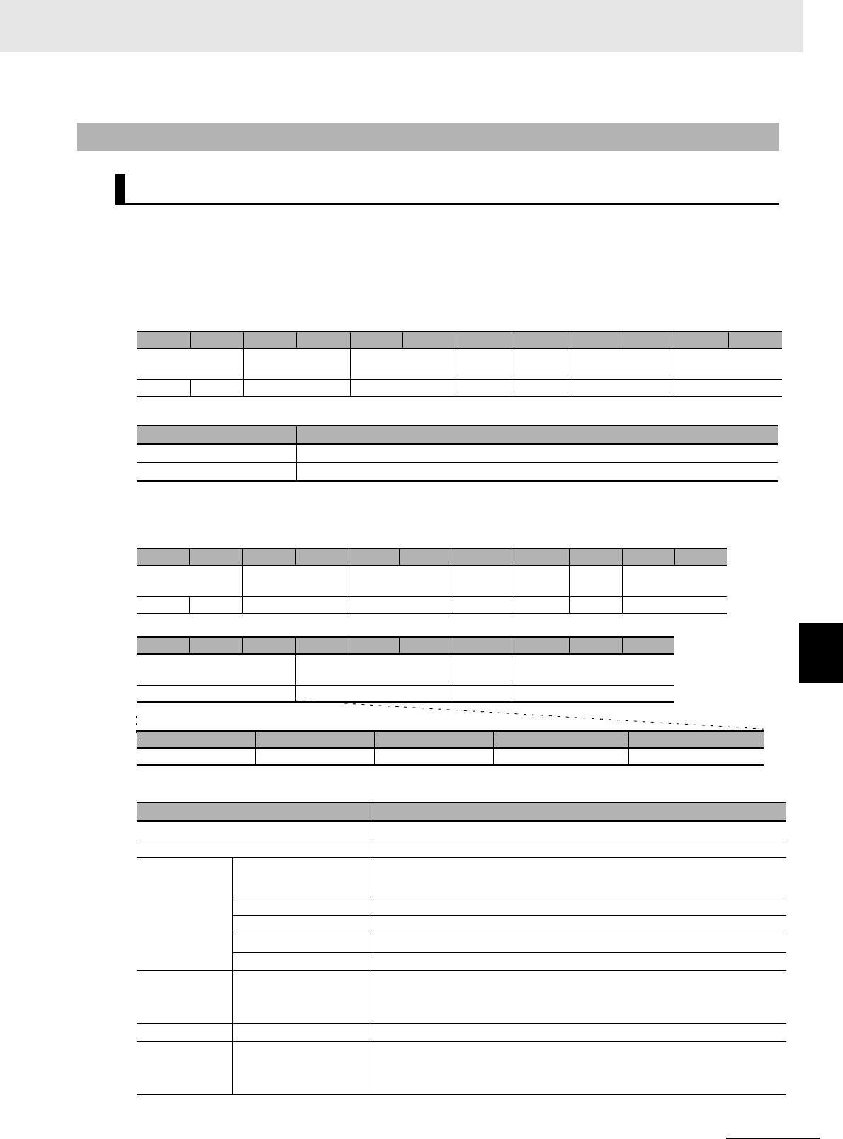
7 - 113
7 Modbus/TCP Communications
UHF RFID System V780-series Reader/Writer User’s Manual (Z389)
7-6 V780 Command Details
7
7-6-9 Maintenance Commands: Log Information
Function
This command is used to check the log of system errors that have occurred in the Reader/Writer.
The system error log is retained even when the Reader/Writer is restarted.
Command Format
Response Formats
• Normal Response
7-6-9 Maintenance Commands: Log Information
GET SYSTEM ERROR LOG
Byte-0 Byte-1 Byte-2 Byte-3 Byte-4 Byte-5 Byte-6 Byte-7 Byte-8 Byte-9 Byte-10 Byte-11
Transaction identi-
fier
Protocol identifier Field length Unit
identifier
Function
code
Register address Word count
X X 0000 hex 0006 hex FF hex 03 hex D600 hex 0079 hex
Parameter Description
Register address The register address (D600 hex) that specifies the system error log information
Word count The number of words in the system error log information to read (0079 hex)
Parameter Description
Byte count The number of bytes in system error log (F2 hex)
Number of records Gives the number of records in the valid data of the system error log.
Newest record
in system error
log
Time information Gives the time information in 8-digit hexadecimal
(actual time flag, hour, minutes, and seconds).
Error code For details, refer to ?9-2-1 ?????? (P.9-3)?.
Reserved (Reserved for future use as error device information.)
Attached information 1 Additional error information 1 (00 hex if there is no attached information)
Attached information 2 Additional error information 2 (00 hex if there is no attached information)
Newest record
− 1 in system
error log
--- ---
... ... ...
Newest record
− 14 in system
error log
--- ---
Byte-0 Byte-1 Byte-2 Byte-3 Byte-4 Byte-5 Byte-6 Byte-7 Byte-8 Byte-9 Byte-10
Transaction identi-
fier
Protocol identifier Field length Unit
identifier
Function
code
Byte
count
Number of records
X X 0000 hex 00F5 hex FF hex 03 hex F2 hex 1 word
Byte-11 ... Byte-26 Byte-27 ... Byte-42 ...
Byte-235
...
Byte-250
Newest record in system
error log
Newest record - 1 in system
error log
... Newest record - 14 in system
error log
16 bytes 16 bytes ... 16 bytes
Time information Error code Reserved Attached information 1 Attached information 2
4 bytes 2 bytes 2 bytes 4 bytes 4 bytes
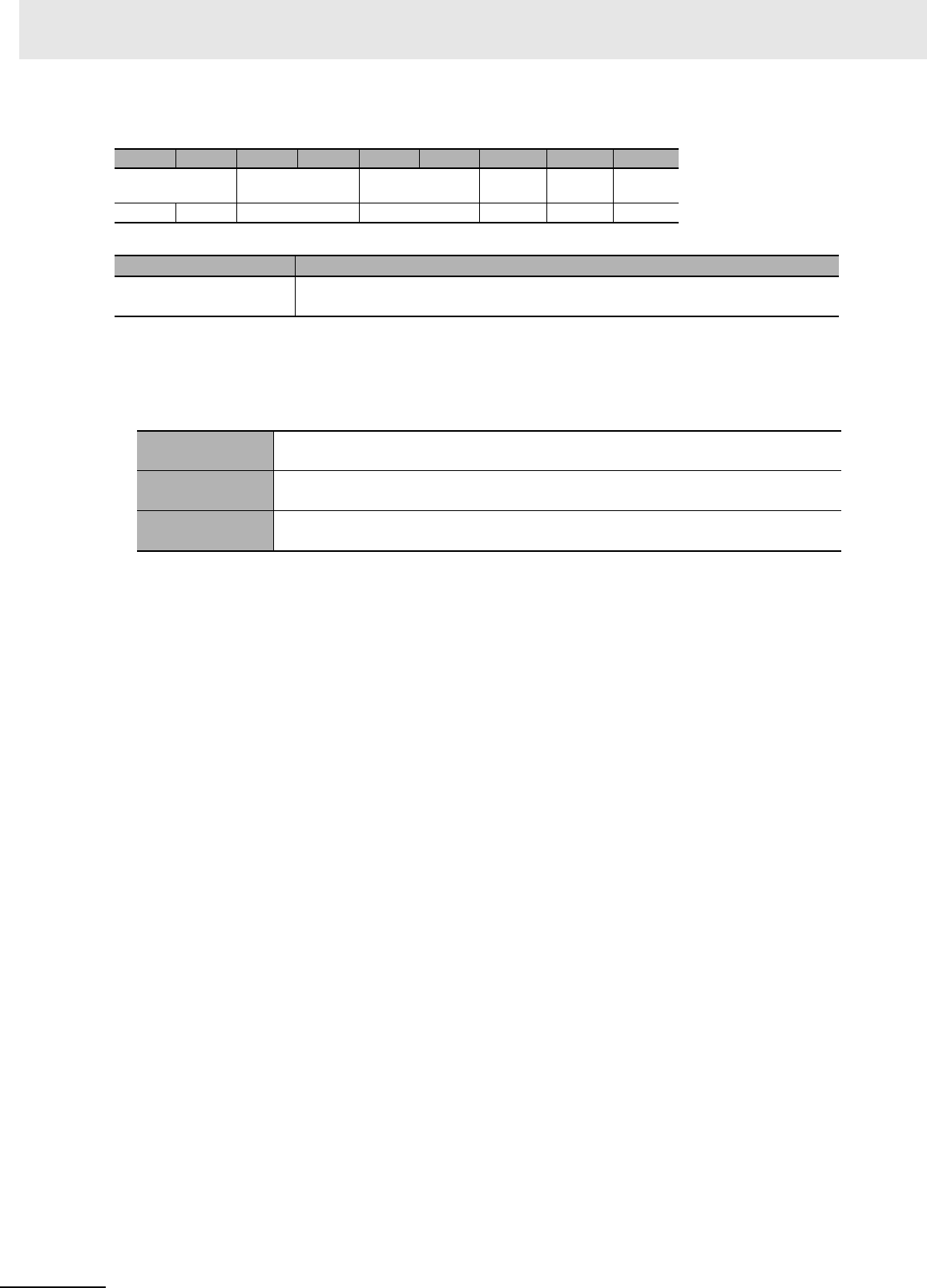
7 Modbus/TCP Communications
7 - 114 UHF RFID System V780-series Reader/Writer User’s Manual (Z389)
• Error Response
Execution Examples
Execution with the Following System Error Log in the Reader/Writer
TX: 000000000006FF03D6000079
RX: 0000000000F5FF03F2000201091F1E80110000000000000000000001091E0A8012
0000000000000000.....00
Byte-0 Byte-1 Byte-2 Byte-3 Byte-4 Byte-5 Byte-6 Byte-7 Byte-8
Transaction identi-
fier
Protocol identifier Field length Unit
identifier
Function
code
Excep-
tion code
X X 0000 hex 0003 hex FF hex 83 hex 1 byte
Parameter Description
Exception code For details, refer to Exception Code on page 7-7 under 7-2-3 Response Format for
Error Completion on page 7-7.
Number of
records
2
Newest record Time information: 09:31:30, Error code: 8011 hex (IP address conflict), Attached infor-
mation: None
Newest record − 1 Time information: 09:30:10, Error code: 8012 hex (BOOTP server connection failed),
Attached information: None

7 - 115
7 Modbus/TCP Communications
UHF RFID System V780-series Reader/Writer User’s Manual (Z389)
7-6 V780 Command Details
7
7-6-9 Maintenance Commands: Log Information
Function
This command clears the log of system errors (fatal errors) that is stored in the Reader/Writer.
Command Format
Response Formats
• Normal Response
• Error Response
CLEAR SYSTEM ERROR LOG
Byte-0 Byte-1 Byte-2 Byte-3 Byte-4 Byte-5 Byte-6 Byte-7 Byte-8 Byte-9 Byte-10 Byte-11
Transaction identi-
fier
Protocol identifier Field length Unit
identifier
Function
code
Register address Word count
X X 0000 hex 0009 hex FF hex 10 hex D700 hex 0001 hex
Byte-12 Byte-13 Byte-14
Byte
count
Clear type
02 hex 2 bytes
Parameter Description
Register address The register address (D700 hex) that specifies clearing the system error log infor-
mation
Word count The number of words for system error log clear (0001 hex)
Byte count The number of bytes for system error log clear (02 hex)
Clear type 0000 hex: Clear all
Byte-0 Byte-1 Byte-2 Byte-3 Byte-4 Byte-5 Byte-6 Byte-7 Byte-8 Byte-9 Byte-10 Byte-11
Transaction identi-
fier
Protocol identifier Field length Unit
identifier
Function
code
Register address Word count
X X 0000 hex 0006 hex FF hex 10 hex D700 hex 0001 hex
Parameter Description
Register address The register address from the command is set.
Word count The word count from the command is set.
Byte-0 Byte-1 Byte-2 Byte-3 Byte-4 Byte-5 Byte-6 Byte-7 Byte-8
Transaction identi-
fier
Protocol identifier Field length Unit
identifier
Function
code
Excep-
tion code
X X 0000 hex 0003 hex FF hex 90 hex 1 byte
Parameter Description
Exception code For details, refer to Exception Code on page 7-7 under 7-2-3 Response Format for
Error Completion on page 7-7.

7 Modbus/TCP Communications
7 - 116 UHF RFID System V780-series Reader/Writer User’s Manual (Z389)
Execution Examples
Execution to Clear the System Error Log in the Reader/Writer
TX: 000000000009FF10D7000001020000
RX: 000000000006FF10D7000001
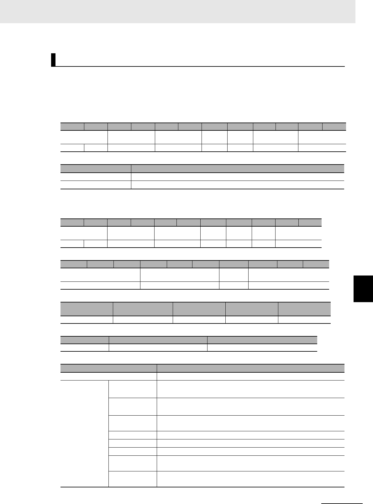
7 - 117
7 Modbus/TCP Communications
UHF RFID System V780-series Reader/Writer User’s Manual (Z389)
7-6 V780 Command Details
7
7-6-9 Maintenance Commands: Log Information
Function
This command is used to check the log of command errors that have occurred in the Reader/Writer.
The command error log information is cleared when the Reader/Writer is restarted.
Command Format
Response Formats
• Normal Response
GET COMMAND ERROR LOG
Byte-0 Byte-1 Byte-2 Byte-3 Byte-4 Byte-5 Byte-6 Byte-7 Byte-8 Byte-9 Byte-10 Byte-11
Transaction identi-
fier
Protocol identifier Field length Unit
identifier
Function
code
Register address Word count
X X 0000 hex 0006 hex FF hex 03 hex D800 hex 0061 hex
Parameter Description
Register address The register address (D800 hex) that specifies the command error log information
Word count The number of words in the command error log to read (0061 hex)
Byte-0 Byte-1 Byte-2 Byte-3 Byte-4 Byte-5 Byte-6 Byte-7 Byte-8 Byte-9 Byte-10
Transaction identi-
fier
Protocol identifier Field length Unit
identifier
Function
code
Byte
count
Number of records
X X 0000 hex 00C5 hex FF hex 03 hex C2 hex 2 bytes
Byte-11 ... Byte-34 Byte-35 ... Byte-58 ... Byte-179 ... Byte-202
Newest record in the command
error log
Newest record - 1 in the com-
mand error log
... Newest record -7 in the command
error log
24 bytes 24 bytes ... 24 bytes
Time information IP address of the
remote device
Transaction identi-
fier Command code Error code
4 bytes 4 bytes 2 bytes 2 bytes 2 bytes
Reserved Attached information 1 Attached information 2
2 bytes 4 bytes 4 bytes
Parameter Description
Number of records Gives the number of records in the valid data of the system error log.
Newest record in
the command
error log
Time information Gives the time information in 8-digit hexadecimal
(actual time flag, hour, minutes, and seconds).
IP address of the
remote device
Gives the IP address that was read in 8-digit hexadecimal.
Example: C0A801C8 hex (192.168.1.200)
Transaction iden-
tifier
The transaction identifier specified in the command that produced the
error
Command code Gives the command code in 8-digit hexadecimal.
Error code For details, refer to ?9-2-1 ?????? (P.9-3)?.
Reserved (Reserved for future use as error device information.)
Attached infor-
mation 1
Gives additional information 1 on the error in 16-digit hexadecimal.
Attached infor-
mation 2
Gives additional information 2 on the error in 16-digit hexadecimal.
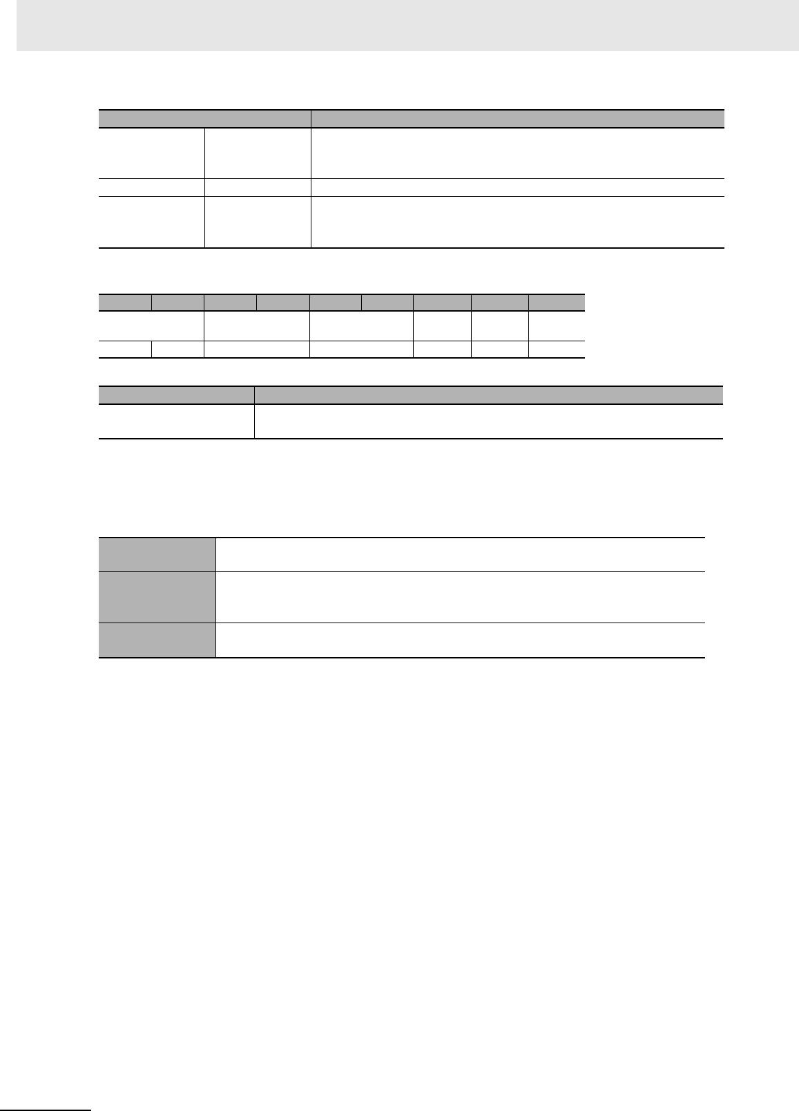
7 Modbus/TCP Communications
7 - 118 UHF RFID System V780-series Reader/Writer User’s Manual (Z389)
• Error Response
Execution Examples
Execution with the Following Command Error Log in the Reader/Writer
TX: 000000000006FF03D8000061
RX: 0000000000C5FF03C2000201091F1EC0A80178000000041005000000000000000
0000001091E0AC0A801780000000320040000000000000000…00
Newest record -
1 in the com-
mand error log
--- ---
... ... ...
Newest record -7
in the command
error log
--- ---
Byte-0 Byte-1 Byte-2 Byte-3 Byte-4 Byte-5 Byte-6 Byte-7 Byte-8
Transaction identi-
fier
Protocol identifier Field length Unit
identifier
Function
code
Excep-
tion code
X X 0000 hex 0003 hex FF hex 83 hex 1 byte
Parameter Description
Exception code For details, refer to Exception Code on page 7-7 under 7-2-3 Response Format for
Error Completion on page 7-7.
Number of
records
2
Newest record
Time information: 09:31:30, IP address: 192.168.1.121, Command code: 0004 hex
(WRITE DATA), Error code: 1005 hex (command parameter error), Attached informa-
tion: None
Newest record - 1 Time information: 09:30:10, IP address: 192.168.1.120, Command code: 0003 hex
(READ DATA), Error code: 2004 hex (address error), Attached information: None
Parameter Description
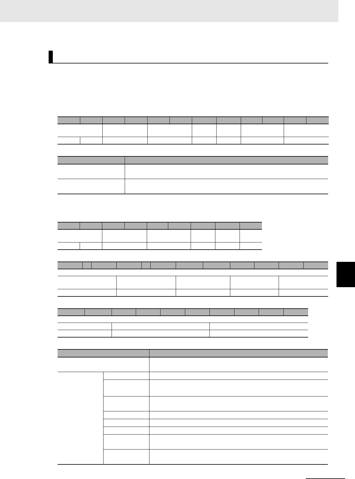
7 - 119
7 Modbus/TCP Communications
UHF RFID System V780-series Reader/Writer User’s Manual (Z389)
7-6 V780 Command Details
7
7-6-9 Maintenance Commands: Log Information
Function
This command is used to check the most recent command error information from the Reader/Writer.
The most recent command error information is cleared when the Reader/Writer is restarted.
Command Format
Response Formats
• Normal Response
GET MOST RECENT COMMAND ERROR INFORMATION
Byte-0 Byte-1 Byte-2 Byte-3 Byte-4 Byte-5 Byte-6 Byte-7 Byte-8 Byte-9 Byte-10 Byte-11
Transaction identi-
fier
Protocol identifier Field length Unit
identifier
Function
code
Register address Word count
X X 0000 hex 0006 hex FF hex 03 hex D900 hex 000C hex
Parameter Description
Register address The register address (D900 hex) that specifies reading the most recent command
error information
Word count The number of words in the most recent command error information to read (000C
hex)
Byte-0 Byte-1 Byte-2 Byte-3 Byte-4 Byte-5 Byte-6 Byte-7 Byte-8
Transaction identi-
fier
Protocol identifier Field length Unit
identifier
Function
code
Byte
count
X X 0000 hex 001B hex FF hex 03 hex 18 hex
Byte-9 ... Byte-12 Byte-13 ... Byte-16 Byte-17 Byte-18 Byte-19 Byte-20 Byte-21 Byte-22
Most recent command error information
Time information IP address of the remote
device
Transaction identifier Command code Error code
4 bytes 4 bytes 2 bytes 2 bytes 2 bytes
Byte-23 Byte-24 Byte-25 Byte-26 Byte-27 Byte-28 Byte-29 Byte-30 Byte-31 Byte-32
Most recent command error information
Reserved Attached information 1 Attached information 2
2 bytes 4 bytes 4 bytes
Parameter Description
Byte count The number of bytes in the most recent command error information that
was read (18 hex)
Most recent com-
mand error infor-
mation
Time information Gives the time information in 8-digit hexadecimal
IP address of the
remote device
Gives the IP address that was read in 8-digit hexadecimal.
Example: C0A801C8 hex (192.168.1.200)
Transaction iden-
tifier
The transaction identifier specified in the command that produced the
error
Command code Gives the command code in 8-digit hexadecimal.
Error code For details, refer to ?9-2-1 ?????? (P.9-3)?.
Reserved (Reserved for future use as error device information.)
Attached infor-
mation 1
Gives additional information 1 on the error in 8-digit hexadecimal.
Attached infor-
mation 2
Gives additional information 2 on the error in 8-digit hexadecimal.

7 Modbus/TCP Communications
7 - 120 UHF RFID System V780-series Reader/Writer User’s Manual (Z389)
• Error Response
Execution Examples
Execution with the Following Most Recent Command Error Information in the Reader/Writer
Time information: 09:31:30, IP address: 192.168.1.121, Command code: 0004 hex (WRITE DATA),
Error code: 1005 hex (command parameter error), Attached information: None
TX: 000000000006FF03D900000C
RX:
00000000001BFF031801091F1EC0A8017800000004100500000000000000000000
Byte-0 Byte-1 Byte-2 Byte-3 Byte-4 Byte-5 Byte-6 Byte-7 Byte-8
Transaction identi-
fier
Protocol identifier Field length Unit
identifier
Function
code
Excep-
tion code
X X 0000 hex 0003 hex FF hex 83 hex 1 byte
Parameter Description
Exception code For details, refer to Exception Code on page 7-7 under 7-2-3 Response Format for
Error Completion on page 7-7.
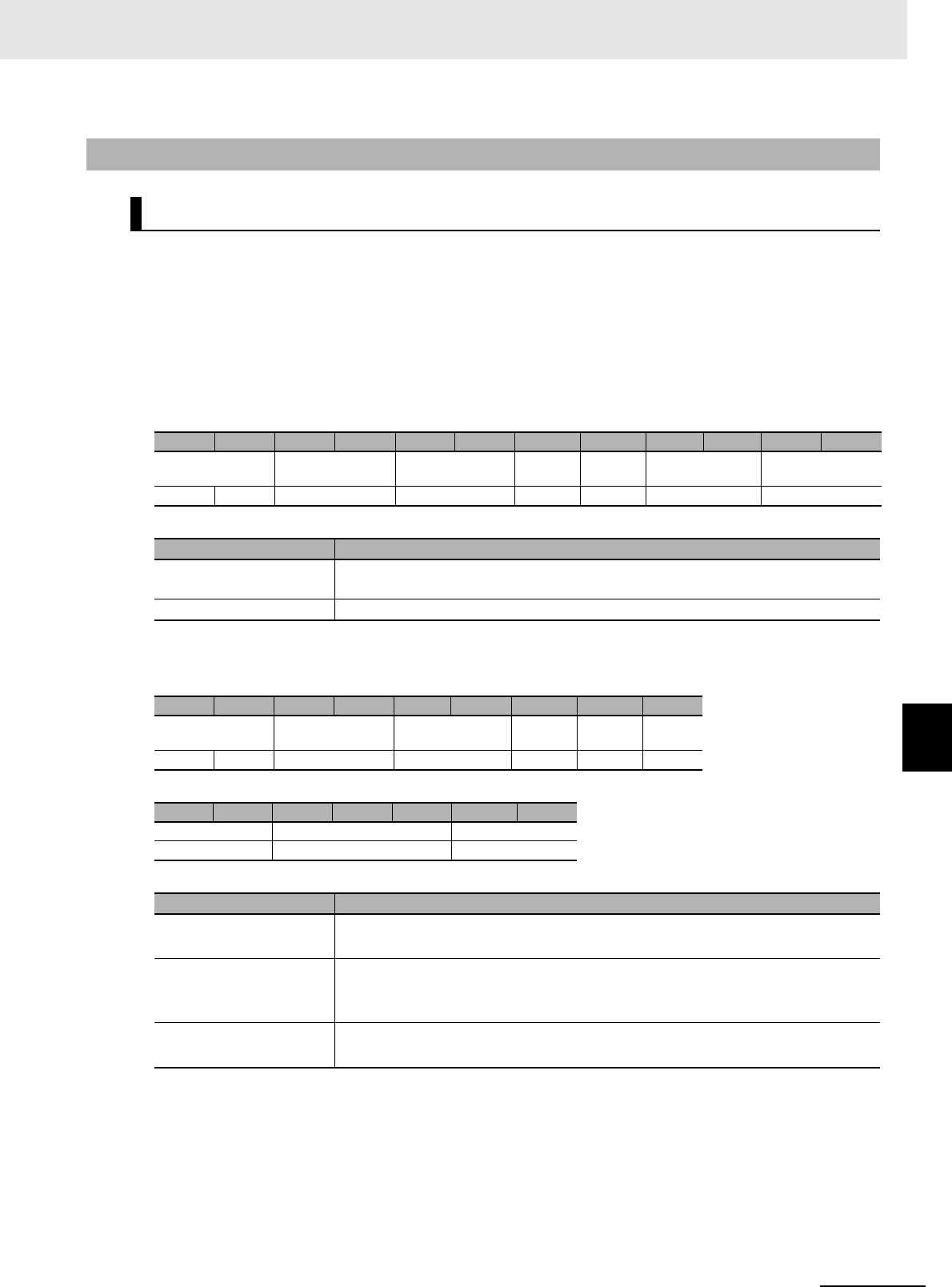
7 - 121
7 Modbus/TCP Communications
UHF RFID System V780-series Reader/Writer User’s Manual (Z389)
7-6 V780 Command Details
7
7-6-10 Maintenance Commands: RF Communications Information
Function
This command us used to check the attached information (i.e., the EPC code and reception level)
that resulted from communications for a single-access command with the immediately preceding RF
Tag .
If communications for the immediately preceding single-access command ended in an error,
attached information of 00 hex will be returned.
Command Format
Response Formats
• Normal Response
7-6-10 Maintenance Commands: RF Communications Information
GET RF TAG ADDITIONAL INFORMATION
Byte-0 Byte-1 Byte-2 Byte-3 Byte-4 Byte-5 Byte-6 Byte-7 Byte-8 Byte-9 Byte-10 Byte-11
Transaction identi-
fier
Protocol identifier Field length Unit
identifier
Function
code
Register address Word count
X X 0000 hex 0006 hex FF hex 03 hex DA00 hex 0021 hex
Parameter Description
Register address The register address (DA00 hex) for reading the attached information for RF Tag
communications
Word count Always 0021 hex.
Byte-0 Byte-1 Byte-2 Byte-3 Byte-4 Byte-5 Byte-6 Byte-7 Byte-8
Transaction identi-
fier
Protocol identifier Field length Unit
identifier
Function
code
Byte
count
X X 0000 hex 0045 hex FF hex 03 hex 42 hex
Byte-9 Byte-10 Byte-11 ... Byte-72 Byte-73 Byte-74
StoredPC EPC code Reception level
2 bytes 62 bytes 2 bytes
Parameter Description
StoredPC Gives the StoredPC data in 4-digit hexadecimal.
The upper 5 bits are the EPC word length.
EPC code Gives the Tag-specific information according to Gen2 standards.
All bytes of the EPC code section that exceed the EPC word length in the StoredPC
are filled with 00 hex.
Reception level Gives the reception level in signed hexadecimal.
FFFF to FF9D hex (-1 to -99) [dBm]

7 Modbus/TCP Communications
7 - 122 UHF RFID System V780-series Reader/Writer User’s Manual (Z389)
• Error Response
Execution Examples
Execution for the Following Attached Information as the Results of Reader/Writer Communications
with the Immediately Preceding RF Tag
StoredPC: 3000 hex, EPC code: 111122223333444455556666 hex, Reception level: -27 (FFE5 hex)
TX: 000000000006FF03DA000021
RX: 000000000045FF0342300011112222333344445555666600…00FFE5
Byte-0 Byte-1 Byte-2 Byte-3 Byte-4 Byte-5 Byte-6 Byte-7 Byte-8
Transaction identi-
fier
Protocol identifier Field length Unit
identifier
Function
code
Excep-
tion
code
X X 0000 hex 0003 hex FF hex 83 hex 1 byte
Parameter Description
Exception code For details, refer to Exception Code on page 7-7 under 7-2-3 Response Format for
Error Completion on page 7-7.
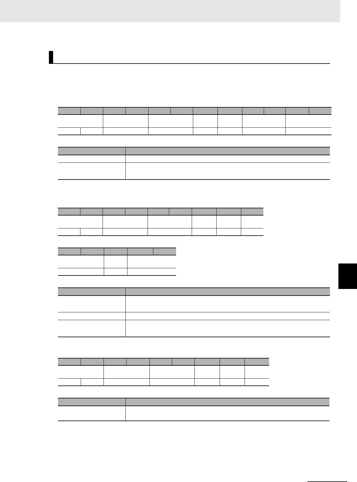
7 - 123
7 Modbus/TCP Communications
UHF RFID System V780-series Reader/Writer User’s Manual (Z389)
7-6 V780 Command Details
7
7-6-10 Maintenance Commands: RF Communications Information
Function
This command measures the ambient noise level around the Reader/Writer.
Command Format
Response Formats
• Normal Response
• Error Response
GET NOISE LEVEL
Byte-0 Byte-1 Byte-2 Byte-3 Byte-4 Byte-5 Byte-6 Byte-7 Byte-8 Byte-9 Byte-10 Byte-11
Transaction identi-
fier
Protocol identifier Field length Unit
identifier
Function
code
Register address Word count
X X 0000 hex 0006 hex FF hex 03 hex DB00 hex 000F hex
Parameter Description
Register address The register address (DB00 hex) for getting the noise level
Word count Always 000F hex.
The noise information for channels 1 to 15 is read at the same time.
Byte-0 Byte-1 Byte-2 Byte-3 Byte-4 Byte-5 Byte-6 Byte-7 Byte-8
Transaction identi-
fier
Protocol identifier Field length Unit
identifier
Function
code
Byte
count
X X 0000 hex 0021 hex FF hex 03 hex 1E hex
Byte-9 Byte-10 ... Byte-37 Byte-38
Channel 1 noise
level
... Channel 15 noise
level
2 bytes ... 2 bytes
Parameter Description
Channel 1 noise level Gives the noise level for channel 1 in signed 2-digit hexadecimal.
FFFF to FF9D hex (-1 to -99) [dBm]
... ...
Channel 15 noise level Gives the noise level for channel 15in signed 2-digit hexadecimal.
FFFF to FF9D hex (-1 to -99) [dBm]
Byte-0 Byte-1 Byte-2 Byte-3 Byte-4 Byte-5 Byte-6 Byte-7 Byte-8
Transaction identi-
fier
Protocol identifier Field length Unit
identifier
Function
code
Excep-
tion code
X X 0000 hex 0003 hex FF hex 83 hex 1 byte
Parameter Description
Exception code For details, refer to Exception Code on page 7-7 under 7-2-3 Response Format for
Error Completion on page 7-7.

7 Modbus/TCP Communications
7 - 124 UHF RFID System V780-series Reader/Writer User’s Manual (Z389)
Execution Examples
Execution When the Reader/Writer Measures the Following Noise Levels
Channel 1 noise level: -40 dBm (FFD8 hex), Channel 2 noise level: -77 (FFB3 hex), … , Channel 15
noise level: -77(FFB3 hex)
TX: 000000000006FF03DB00000F
RX: 000000000021FF031EFFD8FFB3…FFB3
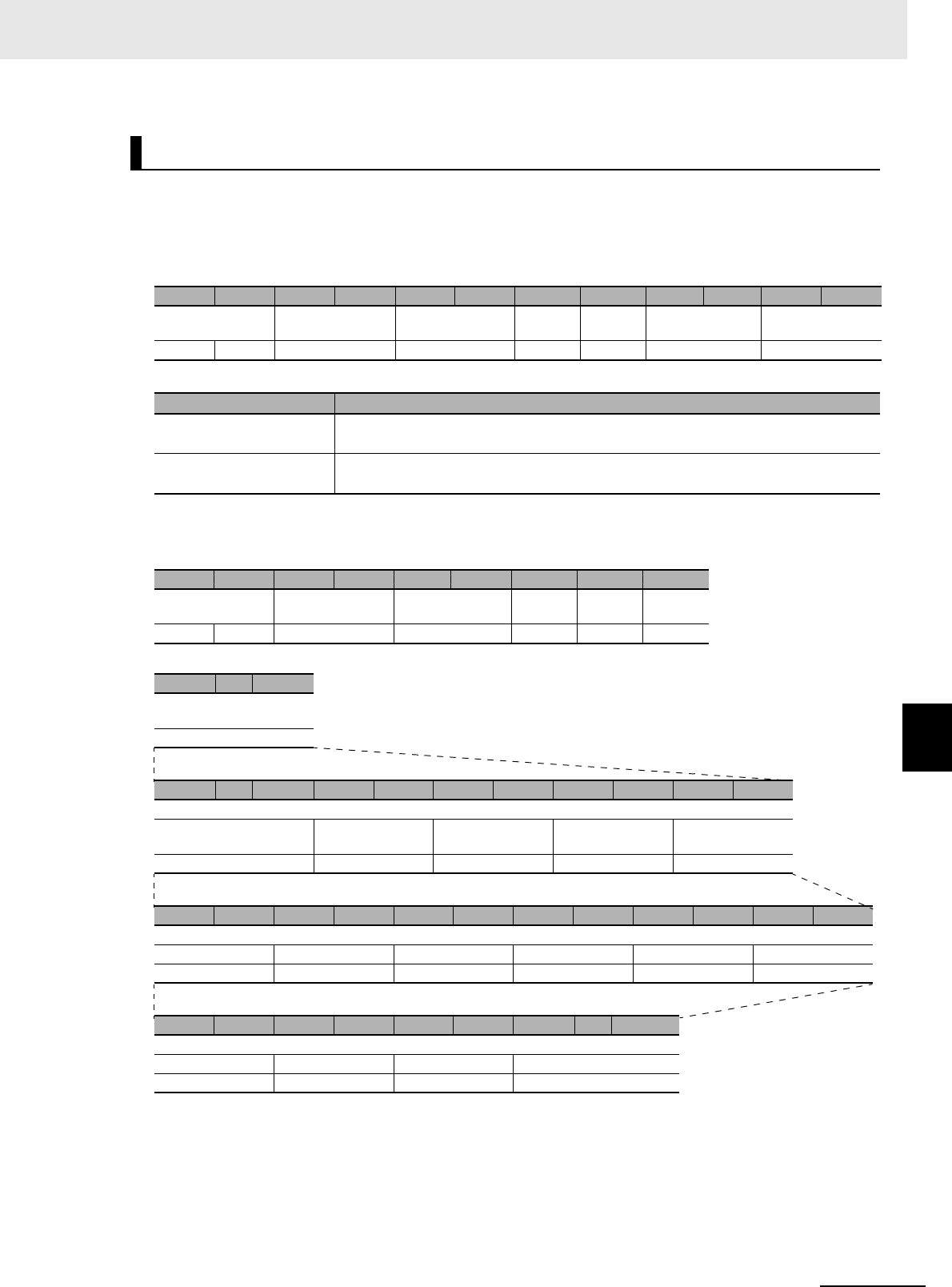
7 - 125
7 Modbus/TCP Communications
UHF RFID System V780-series Reader/Writer User’s Manual (Z389)
7-6 V780 Command Details
7
7-6-10 Maintenance Commands: RF Communications Information
Function
This command gets the most recent communications diagnostic information.
Command Format
Response Formats
• Normal Response
GET COMMUNICATIONS DIAGNOSTIC INFORMATION
Byte-0 Byte-1 Byte-2 Byte-3 Byte-4 Byte-5 Byte-6 Byte-7 Byte-8 Byte-9 Byte-10 Byte-11
Transaction identi-
fier
Protocol identifier Field length Unit
identifier
Function
code
Register address Word count
X X 0000 hex 0006 hex FF hex 03 hex DC00 hex 002E hex
Parameter Description
Register address The register address (DC00 hex) for reading the communications diagnostic infor-
mation
Word count The number of words in the communications diagnostic information to read (002E
hex)
Byte-0 Byte-1 Byte-2 Byte-3 Byte-4 Byte-5 Byte-6 Byte-7 Byte-8
Transaction identi-
fier
Protocol identifier Field length Unit
identifier
Function
code
Byte
count
X X 0000 hex 005F hex FF hex 03 hex 5C hex
Byte-9 ... Byte-88
Most recent communications
diagnostic information
92 bytes
Byte-9 ... Byte-12 Byte-13 Byte-14 Byte-15 Byte-16 Byte-17 Byte-18 Byte-19 Byte-20
Communications diagnostic information
Time information Command code Error code Diagnostic results Detailed diagnos-
tic results
4 bytes 2 bytes 2 bytes 2 bytes 2 bytes
Byte-21 Byte-22 Byte-23 Byte-24 Byte-25 Byte-26 Byte-27 Byte-28 Byte-29 Byte-30 Byte-31 Byte-32
Communications diagnostic information
Reserved 1 Reserved 2 Reserved 3 Reserved 4 Reception level Noise level
2 bytes 2 bytes 2 bytes 2 bytes 2 bytes 2 bytes
Byte-33 Byte-34 Byte-35 Byte-36 Byte-37 Byte-38 Byte-39 ... Byte-100
Communications diagnostic information
Reserved 5 Reserved 6 Stored PC EPC code
2 bytes 2 bytes 2 bytes 62 bytes
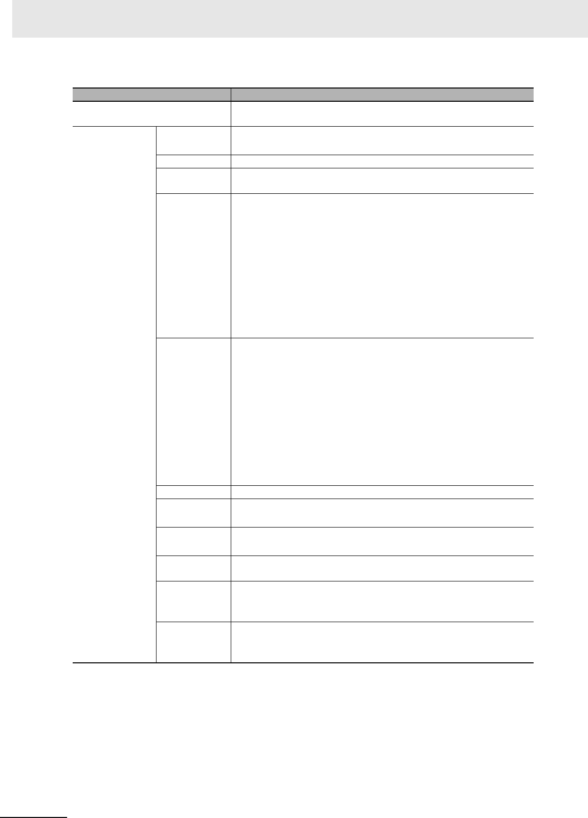
7 Modbus/TCP Communications
7 - 126 UHF RFID System V780-series Reader/Writer User’s Manual (Z389)
*1. All of the most recent communications diagnostic information will be 00 hex if communications diagnostics
are disabled.
*2. This data is output for diagnostic processing only in Focus Mode. It is not output in any other mode.
Parameter Description
Byte count The number of bytes in the most recent communications diagnosis infor-
mation (5C hex)
Most recent com-
munications diag-
nostic information
Time informa-
tion
Gives the time information in 8-digit hexadecimal
(actual time flag, hour, minutes, and seconds).
Command code Gives the command code in 8-digit hexadecimal.
Error code For details, refer to Exception Code on page 7-7 under Response Format
for Error Completion on page 7-7.
Diagnostic
results
Gives the diagnostic results in 4-digit hexadecimal.
FFFF hex: Error (Set when the error code is not normal.)
0000 hex: Normal
0001 hex: Insufficient power to send
0002 hex: Insufficient power to receive
0003 hex: Too much noise
0005 hex: Insufficient read data (Diagnostic processing for these results
is performed only in Focus Mode.)
0006 hex: Excessive read data (Diagnostic processing for these results is
performed only in Focus Mode.)
Diagnostic
details
Gives the diagnostic details in 4-digit hexadecimal.
Bit 0: Insufficient power to send flag
Bit 1: Insufficient power to receive flag
Bit 2: Too much noise
Bit 3: Reserved
Bit 4: Insufficient data read flag
Bit 5: Excessive data read flag
Bits 6 to 15: Reserved (all zeros)
*Bits 4 and 5 are output for diagnostic processing only in Focus Mode.
They are not output in any other mode.
Reserved 1 to 4 0000 hex: No specifications
Reception level Gives the reception level in signed 4-digit hexadecimal.
FFFF to FF9D hex (-1 to -99) [dBm]
Noise level Gives the noise level in signed 4-digit hexadecimal.
FFFF to FF9D hex (-1 to -99) [dBm]
Reserved 5 and
6
0000 hex: No specifications
Stored PC Gives the StoredPC data of the RF Tag for diagnostics in 4-digit hexadec-
imal.
The upper 5 bits are the EPC word length.
EPC code Gives the Tag-specific information according to Gen2 standards.
All bytes of the EPC code section that exceed the EPC word length in the
StoredPC are filled with 00 hex.

7 - 127
7 Modbus/TCP Communications
UHF RFID System V780-series Reader/Writer User’s Manual (Z389)
7-6 V780 Command Details
7
7-6-10 Maintenance Commands: RF Communications Information
• Error Response
Execution Examples
Execution with the Following Most Recent Communications Diagnostic Information in the
Reader/Writer
Time information: 09:31:30, Command code: 0003 hex (READ DATA), Error code: 0000 hex (nor-
mal), Diagnostic results: Insufficient power to send (0001 hex), Diagnostic details: Insufficient power
to send + Insufficient power to receive (0003 hex), Reception level: -41 dBm (FFD7 hex), Noise
level: -70 dBm (FFBA hex), EPC code: 11…11
TX: 000000000006FF03DC00002E
RX: 00000000005FFF035C 01091F1E 0003 0000 0001 0003 0000000000000000 FFD7
FFBA 00000000 30001111…11110000…0000
Byte-0 Byte-1 Byte-2 Byte-3 Byte-4 Byte-5 Byte-6 Byte-7 Byte-8
Transaction identi-
fier
Protocol identifier Field length Unit iden-
tifier
Function
code
Excep-
tion code
X X 0000 hex 0003 hex FF hex 90 hex 1 byte
Parameter Description
Exception code For details, refer to Exception Code on page 7-7 under 7-2-3 Response Format for
Error Completion on page 7-7.

7 Modbus/TCP Communications
7 - 128 UHF RFID System V780-series Reader/Writer User’s Manual (Z389)