On Track Innovations OTI-SAT5000 Contactless Smart Card Reader User Manual
On Track Innovations Ltd Contactless Smart Card Reader Users Manual
Users Manual

Z.H.R Industrial Zone P.O. Box 32 Rosh Pina 12000 Israel Tel: 972-4-6868000 Fax: 972-4-6938887
Saturn 5000
User Manual
Preliminary
On Track Innovations Ltd.
(O T I)
Confidential & Proprietary

Saturn 5000 User Manual Preliminary
Revision History
Confidential & Proprietary page A
Revision History
Version Description Date Author
Preliminary First draft 23-February 2004 Avner
Preliminary Added mounting options and minor changes 24 February 2004 Avner
Preliminary Added mounting options and minor changes 01 March 2004 Avner
Preliminary Added explanation on options 07 March 2004 Avner
Preliminary Added power supply requirements and
contact information 16 January 2005 Avner
Preliminary Edit:
! Power supply requirements
! FCC compliance statement
! RF power output to 400mW
28 January 2005 Hemy

Saturn 5000 User Manual Preliminary
FCC Compliance
Confidential & Proprietary page B
FCC Compliance
This device (Saturn 5000) complies with Part 15, of the FCC Rules.
Operation is subject to the following two conditions:
1. This device may not cause harmful interference,
and
2. This device must accept any interference received, including
interference that may cause undesired operation
NOTE: This equipment has been tested and found to comply with the limits for a
Class B digital device, pursuant to Part 15 of the FCC Rules. These limits are designed
to provide reasonable protection against harmful interference in a residential
installation. This equipment generate, uses and can radiate radio frequency energy
and, if not installed and used in accordance with the instructions, may cause harmful
interference to radio communications. However, there is no guarantee that interference
will not occur in a particular installation. If this equipment does cause harmful
interference to radio or television reception, which can be determined by turning the
equipment off and on, the user is encouraged to try to correct the interference by one
or more of the following measures:
-- Reorient or relocate the receiving antenna.
-- Increase the separation between the equipment and receiver.
-- Connect the equipment into an outlet on a circuit different
from that to which the receiver is connected.
-- Consult the dealer or an experienced radio/TV technician for help.
Changes or modifications in this equipment, not expressly approved by the party
responsible for compliance (On Track Innovations Ltd,) could void the user’s
authority to operate the equipment.
FCC ID: JNX-OTI-SAT5000
Responsible Party:
OTI America Inc.
1601 South DeAnza Blvd.
Cupertino, CA95014
USA
Phone: 408-252-0333

Saturn 5000 User Manual Preliminary
NOTICE
Confidential & Proprietary page C
NOTICE
This manual contains intellectual property, including but not
limited, to trade secrets and know-how, operation procedures
and production procedures that belong solely to OTI.
Disclosure and/or use and/or reproduction of any part of the
above are strictly forbidden, except under a written license
from OTI.

Saturn 5000 User Manual Preliminary
Table of Contents
Confidential & Proprietary page D
Table of Contents
REVISION HISTORY...................................................................................................................................A
FCC COMPLIANCE.....................................................................................................................................B
NOTICE..........................................................................................................................................................C
TABLE OF CONTENTS...............................................................................................................................D
1 INTRODUCTION ..................................................................................................................................5
1.1 READER WITH PAYPASS™ APPLICATION .........................................................................................7
2 TECHNICAL SPECIFICATIONS .......................................................................................................8
2.1 PRODUCT FEATURES.........................................................................................................................8
2.2 PRODUCT SPECIFICATIONS................................................................................................................9
3 READER INTERFACE OPTIONS....................................................................................................11
3.1 READER CONNECTORS ...............................................................................................................11
3.2 RS232 INTERFACE......................................................................................................................11
3.3 MAGNETIC CARD EMULATOR COIL INTERFACE .........................................................................12
3.4 MSR-PS2 INTERFACE ................................................................................................................13
3.5 MSR-RS232 INTERFACE ............................................................................................................14
3.6 MSR HEAD INTERFACE..............................................................................................................15
4 WIRING DIAGRAMS .........................................................................................................................16
4.1 RS232 WIRING ...............................................................................................................................16
4.2 MAGNETIC CARD EMULATOR COIL WIRING...................................................................................16
4.3 MSR PS2 WIRING ..........................................................................................................................17
4.4 MSR RS232 WIRING ......................................................................................................................18
5 MOUNTING OPTIONS ......................................................................................................................19
5.1 MOUNTING HOLES AND CONNECTOR FIELD LAYOUT ......................................................................19
5.2 CRADLE MOUNT – COUNTER TOP...................................................................................................20
5.3 CRADLE MOUNT - BEHIND GLASS ..................................................................................................21
5.4 METAL STAND OPTION...................................................................................................................22
5.5 WALL MOUNT OPTION ....................................................................................................................23

Saturn 5000 User Manual Preliminary
Introduction
Confidential & Proprietary page 5
1 Introduction
OTI’s SATURN 5000 is a sophisticated stylishly designed contactless card
reader designed for contactless payment and loyalty applications providing
unsurpassed cost to performance value.
The reader communicates with ISO14443A&B and Mifare cards and
supports major financial contactless card programs including MasterCard’s’
PayPass™.
The Saturn 5000 employs OTI’s patented matched antenna technology to
provide:
• Highly efficient power to card transfer
• Reliable and stable reader/card communication
The Saturn 5000 is a combined microprocessor based ISO14443 A&B
proximity transceiver with on board antenna, indicator leds and buzzer in a
plastic enclosure H - 6.4” (163.5mm), W – 4.2” (105mm), D – 0.75”
(19mm)
The reader is designed as an on-counter device with mounting holes for
connection to various stands. Reader can also be mounted behind glass
allowing contactless communication with contactless cards and tags through
the glass.
Unit rating
• Nominal supply: 12V DC, 200mA
• Allowed supply range: 7-15VDC/2.4W
Power Supply requirements
An external AC/DC adaptor is required with the following specifications:
• Input Voltage: 120VAC/60Hz or 230VAC/50Hz according to the
destination country national electrical code.
• Output voltage: 12VDC.
• Output current: 250-800ma.
• Connector: Round polarized connecter with the following
polarity:
Additional requirements for the AC/DC adaptor:
• Class 2.
• 60950 safety approved
• UL approval for USA/Canada.
Interface Options to POS Terminal via serial communication
• RS232
• RS485
• USB
+
-

Saturn 5000 User Manual Preliminary
Introduction
Confidential & Proprietary page 6
Interface Options to POS Terminal via Magnetic Stripe Reader (MSR)
• MSR PS2
• MSR RS232
• Magnetic card emulator
Note:
A specific reader model supports one serial communication option and
optionally one MSR interface option.
Standards
• ISO14443 Type B&A (including Mifare) compliant
• FCC part 15 and EN 301 489-3 compliant
• PayPass™ compliant
Saturn 5000 User Manual Preliminary
Introduction
Confidential & Proprietary page 7
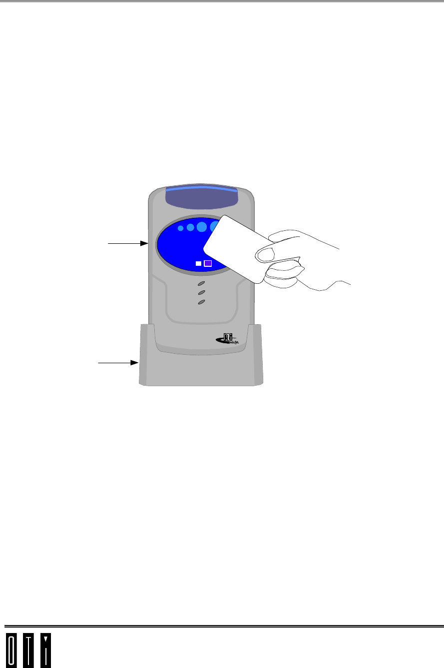
1.1 Reader with PayPass™ Application
When the reader detects a valid PayPass™ card at its antenna it reads track
1 and track 2 data stored in the contactless chip. If the data is valid the
reader gives audiovisual indication and communicates the track data to the
merchant’s POS system.
Four programmable LEDs behind a transparent cover on top of the reader
give status indication. Led at far left indicates system ready, other three leds
and buzzer indicate data read successfully from valid card.
An oval PayPass™ sticker covering the area over the reader’s antenna
indicates where card should be presented.
Saturn
5000
Cradle
PayPas
mknoc0iunu9 DVYg
by09vb)(AC 0as*&9
8jsa9-ZMI-9(unv)VN
Figure 1-1: Card Presentation

Saturn 5000 User Manual Preliminary
Technical Specifications
Confidential & Proprietary page 8
2 Technical Specifications
2.1 Product Features
" Bi-directional radio frequency interface between Host and
Contactless Smart Cards
" Flexible, software configurable microcomputer-based design.
" Integrated, sophisticated Smart Card Operating System on board.
" High security encryption system (DES/RSA) in the board’s
Operating System (with SAM option on-board).
" 13.56 MHz transmission frequency conforming to ISO 14443
standard.
" Simultaneous transmission of power and bi-directional read write
data to the passive Contactless smart card.
" ISO 14443 Type A/B and Mifare cards support.
" Equidistant read/write transaction operation.
" Signal penetrates virtually any non-conductive material - no contact
or line-of-sight required.
" RS232/485 & USB Communications interface to Host.
" PS2 or RS232 Magnetic Stripe Reader support.
" Magnetic Stripe Emulation Coil support.
" Up to two EMV2000 compliant “on-board” SAMs.
" Four programmable indicator LEDs and buzzer.
" Compliance with FCC Section 15 and I-ETS 300 330 emission limit
requirements.
" Operating temperature range -20° to 70°C (-4° to 158°F).
" Power input from 7.0 to 15VDC/2.2W.
" In system programming of reader firmware to 128KB flash memory
via standard RS232/485/USB communication.
" Optional outputs via RJ45 connector for four external LED
indicators.
" Embedded watchdog timer and full reset on brownout.
Saturn 5000 User Manual Preliminary
Technical Specifications
Confidential & Proprietary page 9
2.2 Product Specifications
Table 2-1: Performance/Electrical Specifications
" RF Interface:
RF Carrier Frequency 13.56 MHz
RF Output 400 mW
Output Short Protection Built-in (continuous)
RF Data Operations Half duplex
ISO 14443 A&B and Mifare Full compliance
" SAM/ Contact Card Interface (up to two channels)
EMV 2000
Data line Bi-directional, Half duplex
Reset line
Clock 5MHz (up to 10MHz@EMV2000)
" Communication Links
RS232 (up to two channels)/485
Signals Transmit, receive
Bit/Byte Protocol Async (start/stop), bit serial,
(, full duplex. @ 232, half @ 485);
data byte=8 data bits, no parity, 2
stop bits, full 8-bit binary data
Flexible protocol. Client defined
baud rate (up to 57,600 baud)
Data Error Checking Message Length, Parity, Frame-bits,
CRC.
Connector/Cable Standard connectors on board
RJ45 for RS232, RS485
USB
Fully 1.01 compliant
Connector cable Standard USB Device (B) connector
USB “Good link” indication Green LED
Saturn 5000 User Manual Preliminary
Technical Specifications
Confidential & Proprietary page 10
Performance/Electrical Specifications (continued)
" Indicators:
Four programmable onboard
LEDs
Buzzer
" Microprocessor Circuit
Microprocessor 80C32 – QFP44 - 24MHz
XTAL 24 MHz
FLASH MEMORY 128Kbyte
RAM 32Kbyte
LOCK-UP PROTECTION Watch Dog Timer
" Electronic Board Power Requirements:
From 7.5 to 15VDC Onboard switching power supply
Maximum Power consumption 2.2W (RF signal ON)
" Mechanical:
Dimensions H-- 6.4” (163.5mm)
W - 4.2” (105mm),
D – 0.75” (19mm)
Weight 190 gr.
Vibrations 10 ÷ 200 Hz @ 2.0G
Environmental
" Temperature:
Operating -20° to 70°C
(-4° to 158°F)
Storage -45° to 85°C
(-49° to 185°F)
" Humidity: 5 to 95% non-condensing
" Tuning: NON
" Regulatory Compliance: EMC directive 89/336/EEC
I-ETS 300 330
FCC Section 15 (US) certified
" Secured Applications Secured applications with SAM
option. (Up to two SAMs)
Saturn 5000 User Manual Preliminary
Reader Interface options
Confidential & Proprietary page 11
3 Reader Interface options
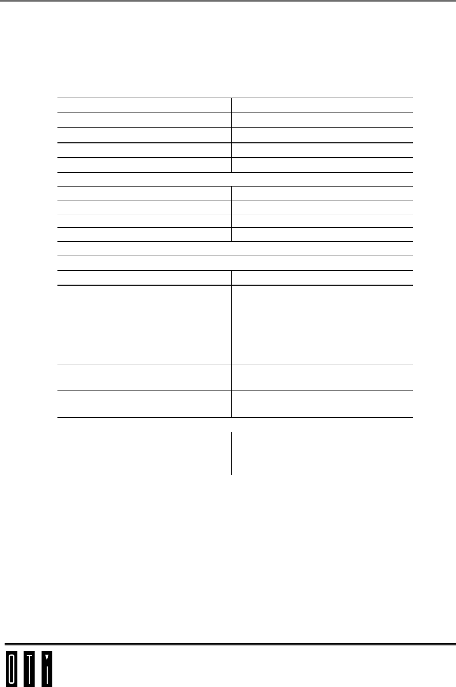
3.1 Reader Connectors
Power Jack
(Optional)
USB
(Optional)
RJ45
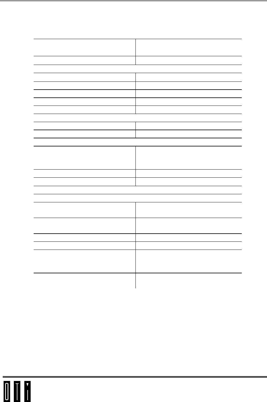
3.2 RS232 Interface
RS232 port can be used to send track data directly to POS terminal or
concentrator via serial RS232 communication. Software integration with
POS is required.
Saturn 5000
POS Terminal
Figure 3-1: RS232 Interface
Saturn 5000 User Manual Preliminary
Reader Interface options
Confidential & Proprietary page 12
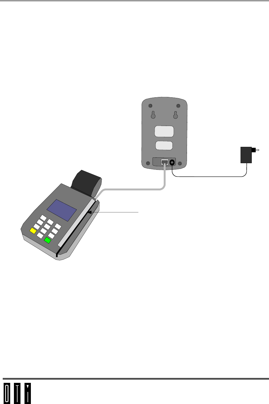
3.3 Magnetic Card Emulator Coil Interface
The reader uses the MSR coil interface to emulate magnetic card signals to
the POS terminal’s magnetic reader head. The POS terminal sees this data
as standard track data read off the cards magnetic stripe. The coil insert unit
is very thin allowing parallel use of standard magnetic stripe cards.
The advantage of this interface option is that it is a plug and play add on to
any existing POS systems supporting magnetic stripe cards and requires no
integration effort.
12V
Power
Adaptor
Saturn 5000
POS Terminal
Magnetic Card
Emulator COIL
Figure 3-2: Magnetic Card Emulator Coil Interface
Saturn 5000 User Manual Preliminary
Reader Interface options
Confidential & Proprietary page 13
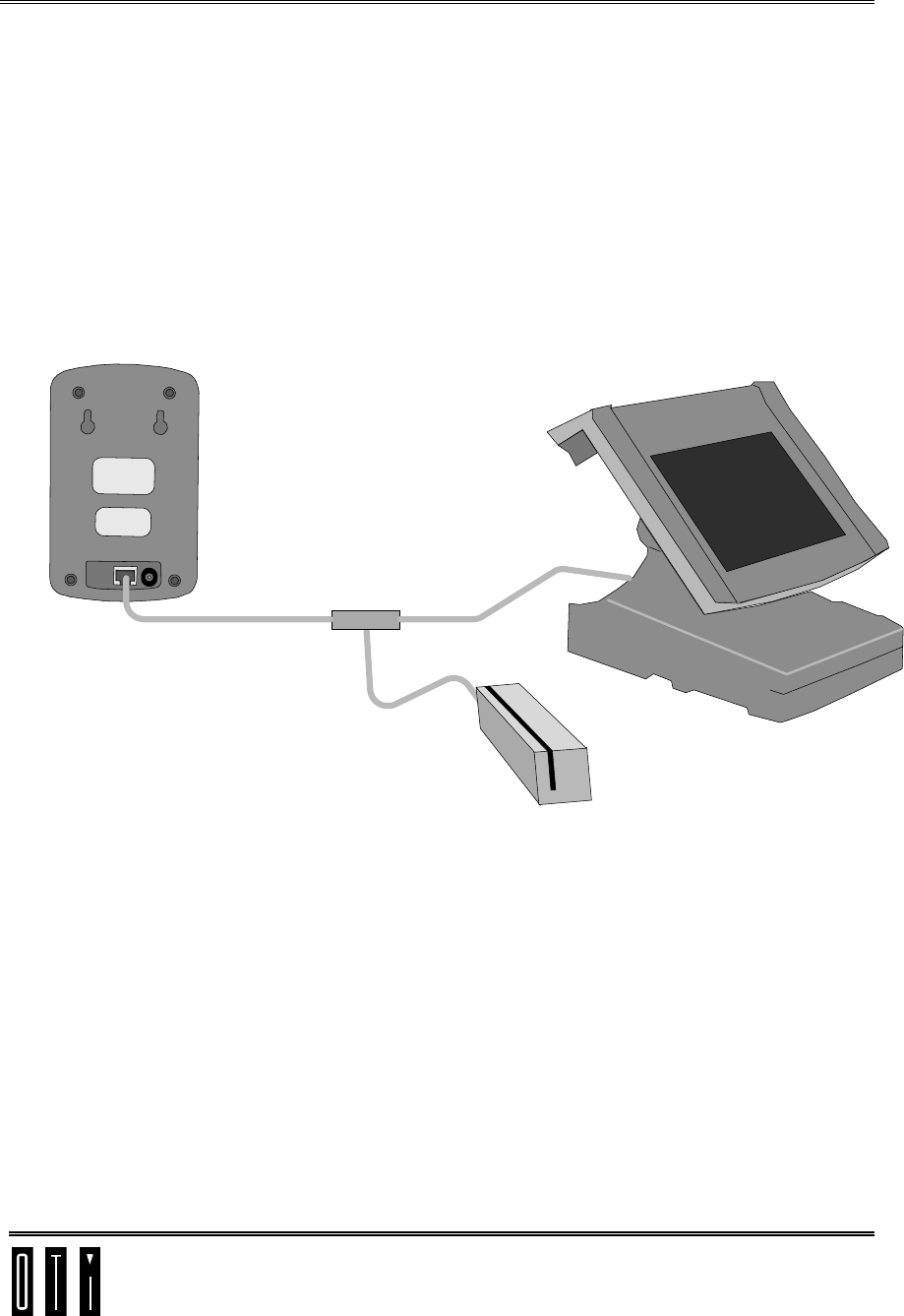
3.4 MSR-PS2
Interface
The reader uses the MSR-PS2 interface to emulate MSR message to the
POS terminal. The POS terminal sees this data as standard track data read
off the cards magnetic stripe. Functionality of PS2 MSR with standard
magnetic stripe cards is preserved.
This interface is intended for POS terminals with separate PS2 MSR that
plugs into POS terminal.
The advantage of this interface option is that it leaves the existing MSR free
and requires no integration effort.
PS2
Magnetic Stripe
Reader
Saturn 5000
POS Terminal
PS2
Splitter
Figure 3-3: MSR PS2 Interface
Saturn 5000 User Manual Preliminary
Reader Interface options
Confidential & Proprietary page 14
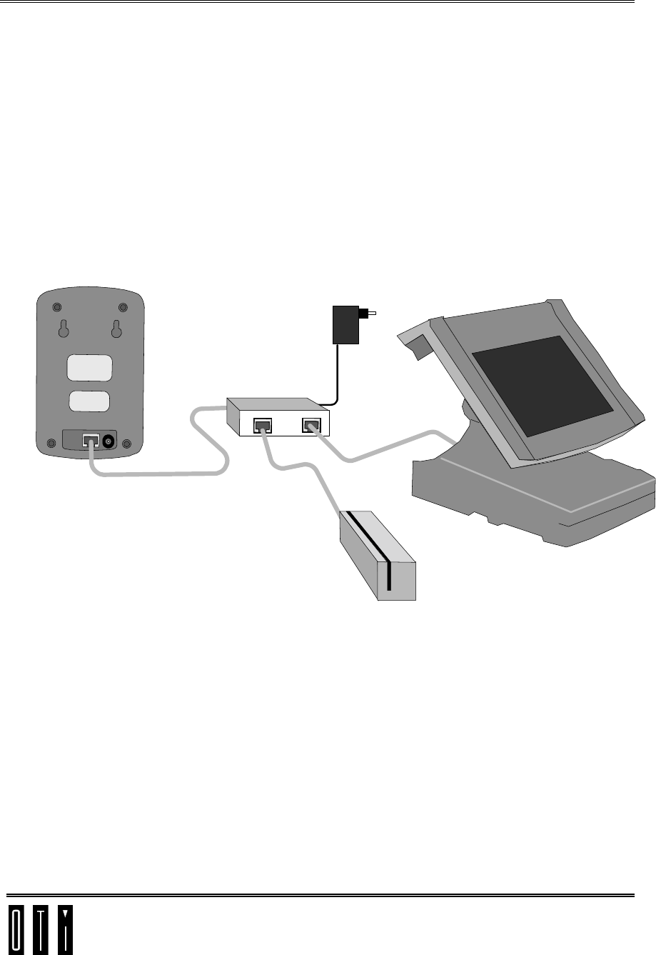
3.5 MSR-RS232 Interface
The reader uses MSR-RS232 interface to emulate MSR message to the POS
terminal. The POS terminal sees this data as standard track data read off the
cards magnetic stripe. Functionality of MSR-RS232 with standard magnetic
stripe cards is preserved.
This interface is intended for POS terminals with separate MSR-RS232 that
plugs into POS terminal.
The advantage of this interface option is that it leaves the existing MSR free
and requires no integration effort.
RS232
Magnetic Stripe
Reader
Saturn 5000
POS Terminal
12V
Power
Adaptor
Breakout Box
Figure 3-4: MSR RS232 Interface
Saturn 5000 User Manual Preliminary
Reader Interface options
Confidential & Proprietary page 15
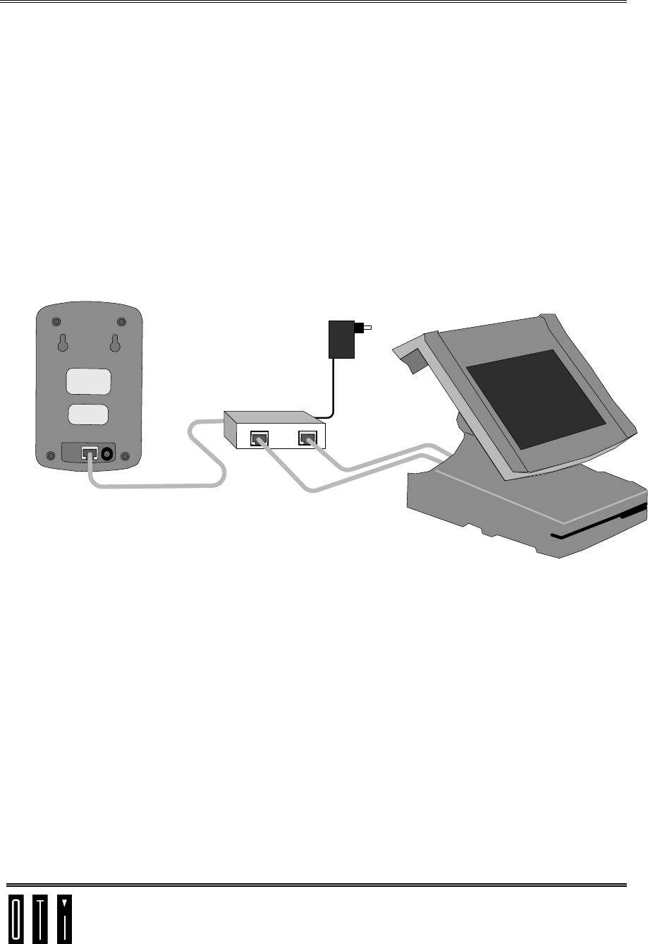
3.6 MSR Head Interface
The reader uses the MSR head interface to emulate MSR head signals sent
from the MSR head to the POS terminal. The POS terminal sees this data as
standard track data read off the cards magnetic stripe. Functionality of MSR
head with standard magnetic stripe cards is preserved.
This interface is intended for POS terminals like the Radiant with a
magnetic head that plugs directly into POS terminal with out PS2 or RS232
convector.
The advantage of this interface option is that it leaves the existing MSR free
and requires no integration effort.
Saturn 5000
POS Terminal
12V
Power
Adaptor
Breakout Box
Figure 3-5: MSR Head Interface
Saturn 5000 User Manual Preliminary
Wiring Diagrams
Confidential & Proprietary page 16
4 Wiring Diagrams
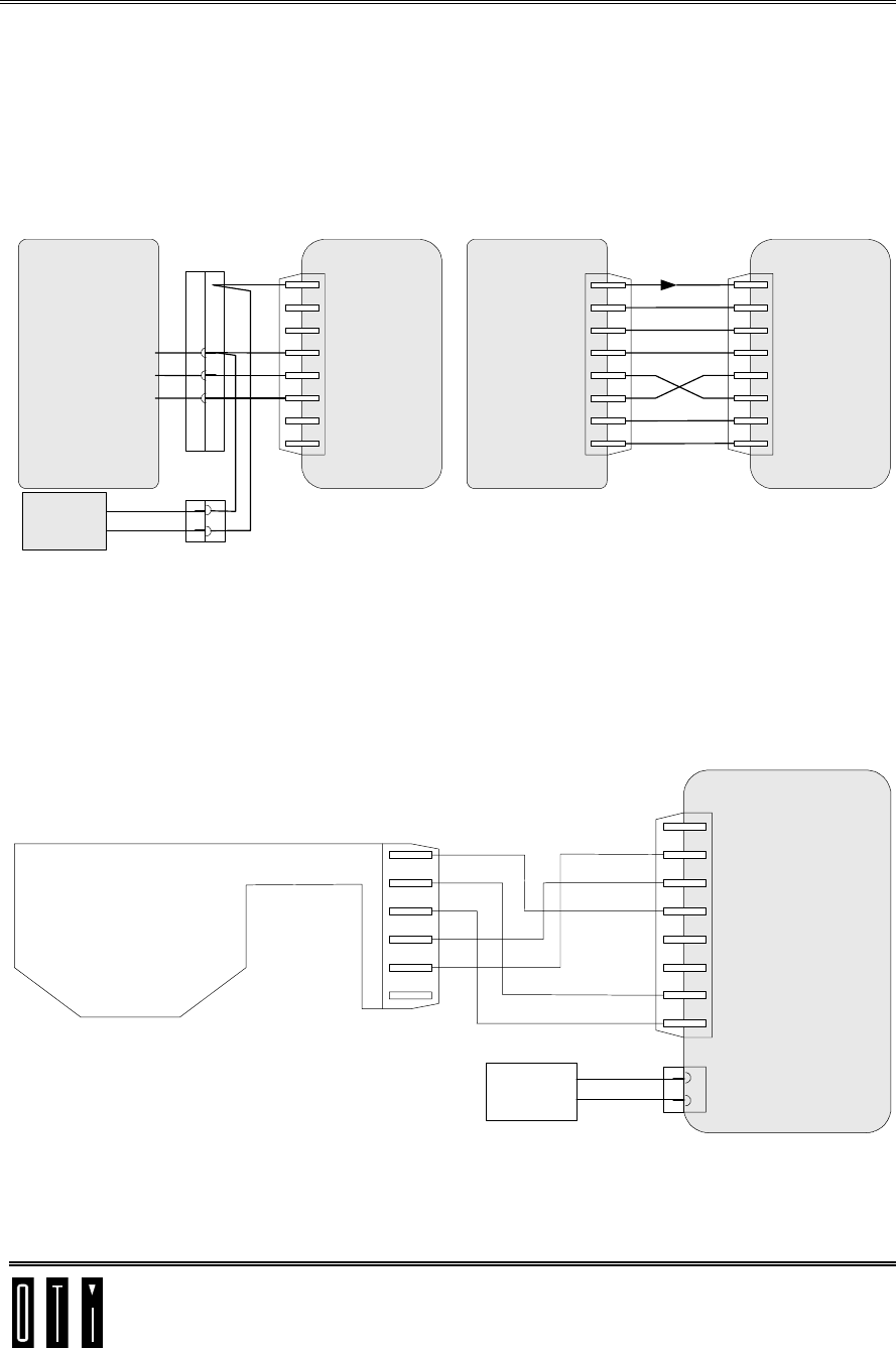
4.1 RS232 Wiring
1
2
3
4
5
6
7
8
GND
RXD
TXD
RJ45
Saturn 5000
+V
1
2
3
4
5
6
7
8
GND
RXD
TXD
RJ45
+9V
Terminal (VeriFone)
1
2
3
4
5
6
7
8
GND
RXD
TXD
RJ45
Saturn 5000
+V
GND
RXD
TXD
Terminal (Hypercom)
D9
5
3
2
FM
Power
jack
12V+
0V
Power
Supply
PIN Pad
Figure 4-1: RS232 Wiring
4.2 Magnetic Card Emulator Coil Wiring
1
2
3
4
5
6
7
8
GND
RXD
TXD
RJ45
Saturn 5000
1
2
3
4
5
6
RJ11
Magnetic Card
Emulator Coil
(OMNI 3200)
T1COM
T1A
T2COM
T2A
12V+
0V
Power
Supply Power
jack
W
GN
Y
BK
RD
Figure 4-2: MC Emulator Coil Wiring
Saturn 5000 User Manual Preliminary
Wiring Diagrams
Confidential & Proprietary page 17
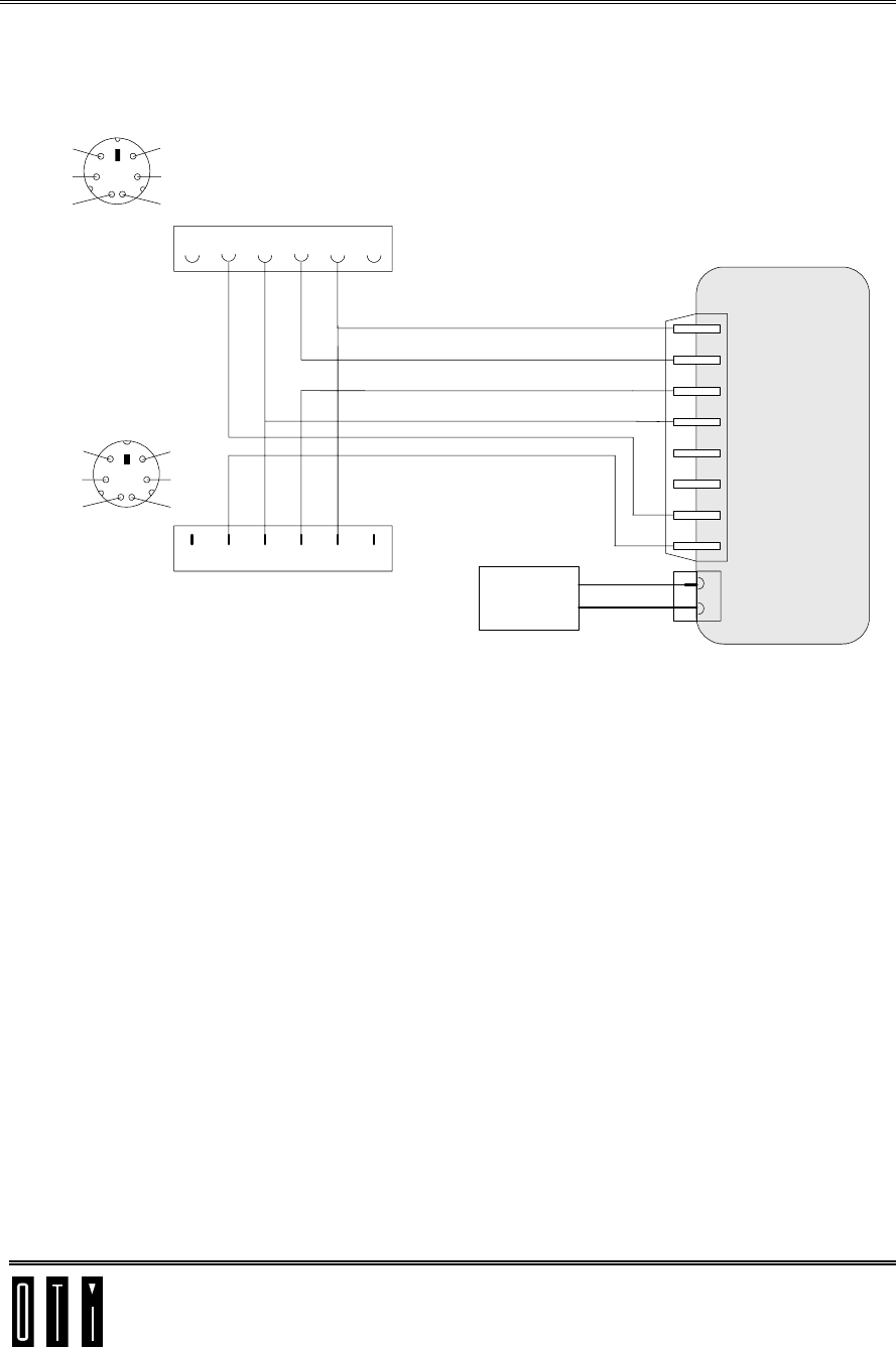
4.3 MSR PS2 Wiring
12
4
3
56
1
2
3
4
5
6
7
8
GND
CLK Slave
CLK Host
5V-PS2
RXD
TXD
RJ45
Saturn 5000
DATA Host
DATA Slave
453126
453126
PS2
FEMALE
Host
Keyboard / MSR
12V+
0V
Power
Supply Power
jack
5V
CLK
GND
DATA
NC
NC
PS2
MALE
1
2
43
5
6
5V
CLK
GND
DATA
NC
NC
Figure 4-3: MSR PS2 Wiring
Saturn 5000 User Manual Preliminary
Wiring Diagrams
Confidential & Proprietary page 18
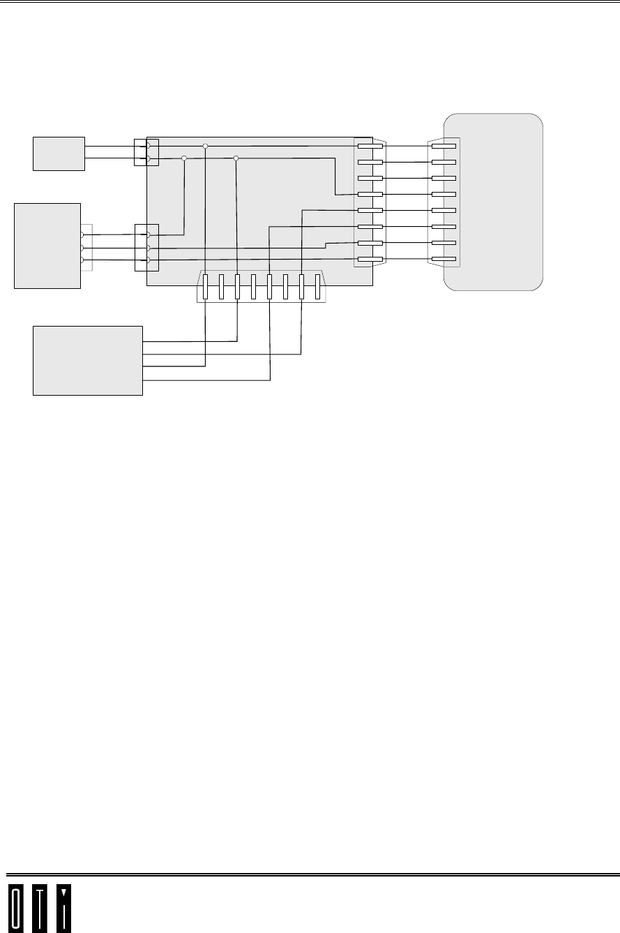
4.4 MSR RS232 Wiring
1
2
3
4
5
6
7
8
GND
RXD
TXD
RJ45
Saturn 5000
RXD2
TXD2
+V
RJ45
RJ45
12345678
D9
5
3
2
FM
+12V
RXD
GND
MS Data
3
7
1
5
Jarltech
MSR
Power
jack
5
3
2
F
D9
12V+
0V
Power
Supply
1
2
3
4
5
6
7
8
POS
Terminal
Breakout Box
Figure 4-4: MSR RS232 Wiring
Saturn 5000 User Manual Preliminary
Mounting Options
Confidential & Proprietary page 19
5 Mounting Options
The Saturn 5000 comes with a cradle for easy counter top applications.
Cradle is also used for mounting reader behind glass
Two mounting holes in back of reader are intended for optional mounting on
various metal stands supplied by others or for mounting on wall.
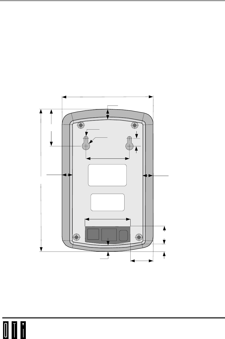
5.1 Mounting Holes and connector field layout
Note: All dimensions in millimeters
105
12.0
R2.5
R4.5
9.0
50.0
12.0
12.0
42.3
163.5
52.7
7.0
20.5
8.8
26
Mounting Holes
Connector Field
Figure 5-1: Mounting holes and connector field layout
Saturn 5000 User Manual Preliminary
Mounting Options
Confidential & Proprietary page 20
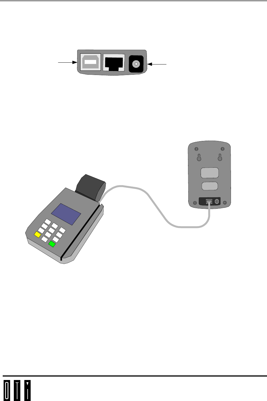
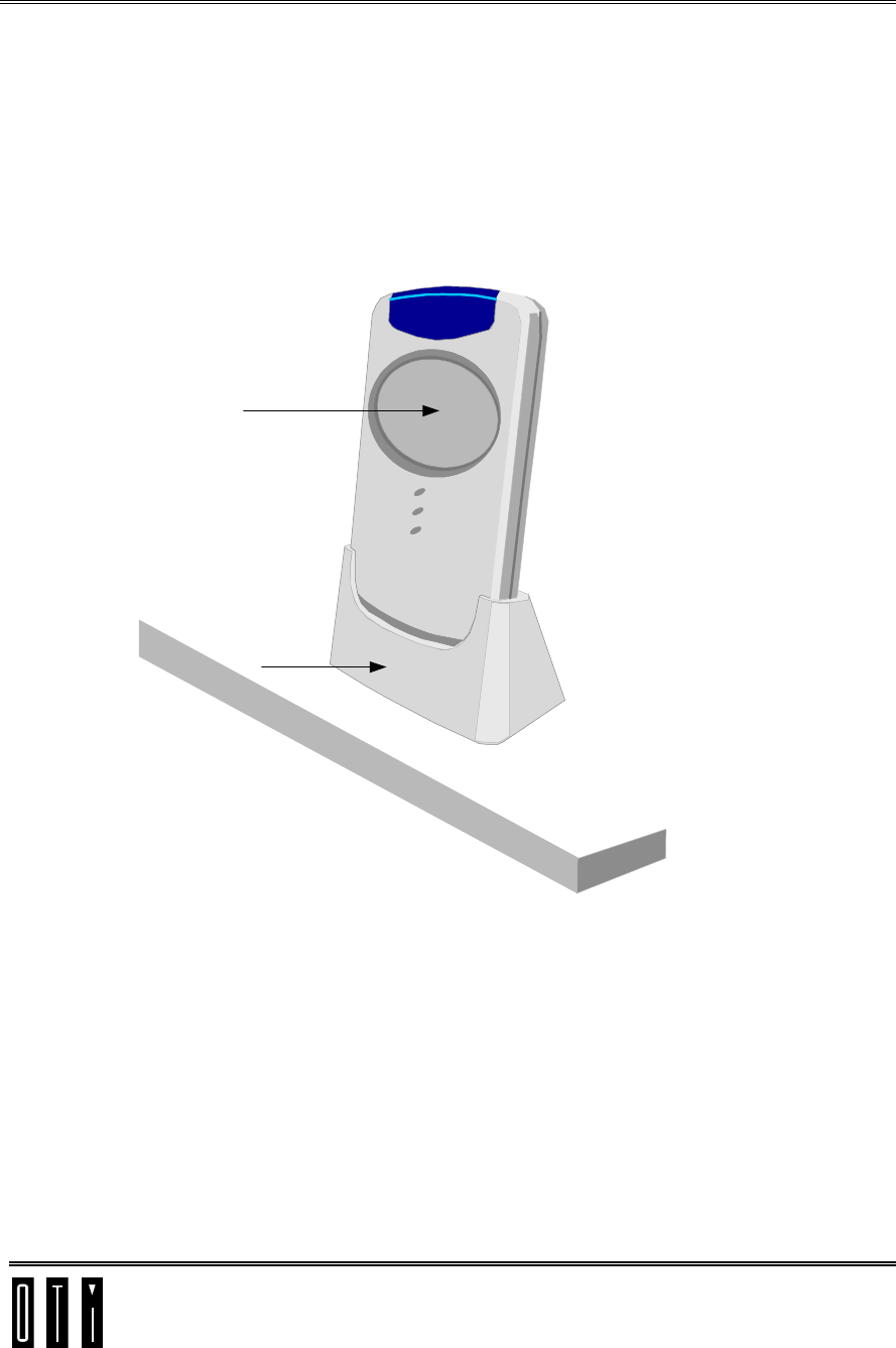
5.2 Cradle Mount – Counter Top
Place the cradle at desired position on counter.
Slip Saturn 5000 into cradle.
Saturn 5000
Cradle
Counter
Figure 5-2: Cradle
Saturn 5000 User Manual Preliminary
Mounting Options
Confidential & Proprietary page 21
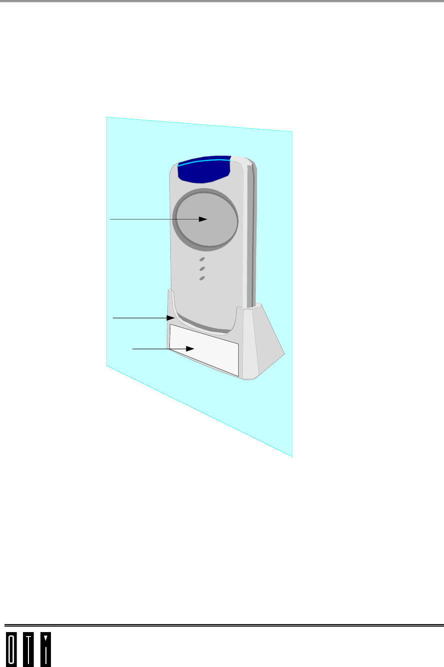
5.3 Cradle Mount - Behind Glass
Glue cradle to glass with double side adhesive.
Slip Saturn 5000 into cradle.
Saturn 5000
Cradle
Adhesive
Glass
Figure 5-3: Behind Glass
Saturn 5000 User Manual Preliminary
Mounting Options
Confidential & Proprietary page 22
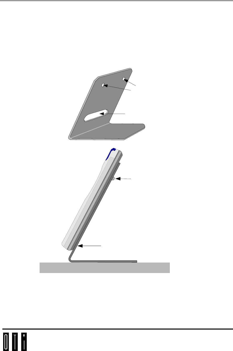
5.4 Metal Stand Option
The Saturn 5000 reader can be connected to a metal stand for optional
counter top mounting.
The metal stand for this option is not supplied with the reader.
See Figure 5-1 for position of connector field and mounting holes.
Hole around
connector field
Holes for
mounting screws
Metal Stand
Mounting
Screws
Figure 5-4: Metal Stand
Saturn 5000 User Manual Preliminary
Mounting Options
Confidential & Proprietary page 23
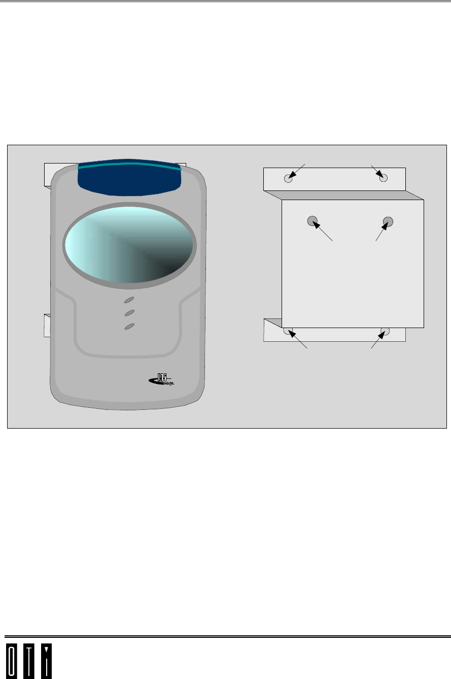
5.5 Wall mount option
Mounting hole at back of reader see Figure 5-1 can also be used for wall
mounting. A metal wall mount bracket as shown in Figure 5-5 below is
suggested.
The metal wall mount bracket is not supplied with reader.
Saturn Mounting holes
Wall Mounting holes
Wall Mounting holes
Wall Mount Bracket
Figure 5-5: Wall Mount Option