On Track Innovations OTI-SCIBA2 Contactless Smart Card Reader User Manual Installation Manual 15845
On Track Innovations Ltd Contactless Smart Card Reader Installation Manual 15845
Users Manual

Z.H.R Industrial Zone P.O. Box 32 Rosh Pina 12000 Israel Tel: 972-4-6868000 Fax: 972-4-6938887
SCIBA2
User & Installation Manual
Version 1.00
On Track Innovations Ltd.
(O T I)

SCIBA2 User & Installation Manual Version 1.00
Revision History
page A
Revision History
Version Description Date Author
1.00 Preliminary data 15/03/04 Avner
1.00 Minor corrections 18/03/04 Hemy
1.00 Minor corrections 21/03/04 Hemy
1.00 Minor corrections 11/04/04 Hemy
1.00 Minor corrections 13/04/04 Avner

SCIBA2 User & Installation Manual Version 1.00
NOTICE
page B
NOTICE
This manual contains intellectual property, including but not
limited, to trade secrets and know-how, operation procedures
and production procedures that belong solely to OTI.
Disclosure and/or use and/or reproduction of any part of the
above are strictly forbidden, except under a written license
from OTI.

SCIBA2 User & Installation Manual Version 1.00
FCC Compliance
page C
FCC Compliance
OTI SCIBA2 FCC ID: JNX-OTI-SCIBA2
Manufacturer: On Track Innovations Ltd.
This device complies with Part 15, of the FCC Rules.
Operation is subject to the following two conditions:
1. This device may not cause harmful interference, and
2. This device must accept any interference received,
including interference that may cause undesired operation.
NOTE: This equipment has been tested and found to comply with the limits for a
Class B digital device, pursuant to Part 15 of the FCC Rules. These limits are
designed to provide reasonable protection against harmful interference in a
residential installation. This equipment generates, uses and can radiate radio
frequency energy and, if not installed and used in accordance with the
instructions, may cause harmful interference to radio communications.
However, there is no guarantee that interference will not occur in a particular
installation. If this equipment does cause harmful interference to radio or
television reception, which can be determined by turning the equipment off and
on, the user is encouraged to try to correct the interference by one or more of the
following measures:
• Reorient or relocate the receiving antenna.
• Increase the separation between the equipment and receiver.
• Connect the equipment into an outlet on a circuit different from
that to which this receiver is connected.
• Consult the dealer or an experienced radio/TV technician for help
Warning!
Changes or modifications in this equipment, not expressly approved by the party
responsible for compliance (On Track Innovations Ltd,) could void the user’s
authority to operate the equipment.
Warning!
This product was tested with special accessories (shielded cables and/or special
connectors or other), which must be used with the unit to insure compliance.

SCIBA2 User & Installation Manual Version 1.00
FCC Declaration of Conformity
page D
FCC Declaration of Conformity
We, the undersigned,
OTI America
Address: Suite 201, 1601 S. De Anza Blvd., Cupertino, CA 95014
Telephone number: 408-252-0333
Fax number: 408-252-8414
are the Responsible Party for this Declaration, certify and declare under our sole
responsibility that the following equipment:
Brand Type Product description
OTI SCIBA2 Contactless card reader
complies with Part 15 of the FCC Rules. Operation is subject to the following
two conditions: (1) this device may not cause harmful interference, and (2) this
device must accept any interference received, including interference that may
cause undesired operation.

SCIBA2 User & Installation Manual Version 1.00
Table of Contents
page E
Table of Contents
REVISION HISTORY...................................................................................................................................A
NOTICE ..........................................................................................................................................................B
FCC COMPLIANCE .....................................................................................................................................C
FCC DECLARATION OF CONFORMITY ...............................................................................................D
TABLE OF CONTENTS ............................................................................................................................... E
1 INTRODUCTION .............................................................................................................................. 1-1
2 TECHNICAL SPECIFICATIONS ................................................................................................... 2-3
3 SYSTEM CONFIGURATION .......................................................................................................... 3-4
3.1 CIBA2 READER............................................................................................................................ 3-5
3.1.1 Standard Connectors ............................................................................................................... 3-5
3.1.2 Optional Connectors................................................................................................................ 3-6
3.1.3 LEDs........................................................................................................................................ 3-7
3.1.4 Jumpers.................................................................................................................................... 3-7
3.1.5 SAMs........................................................................................................................................ 3-7
3.2 ANTENNA ..................................................................................................................................... 3-9
3.3 POWER SUPPLY............................................................................................................................. 3-9
4 INSTALLATION INSTRUCTIONS .............................................................................................. 4-10
4.1 READER INSTALLATION .............................................................................................................. 4-10
4.2 ANTENNA INSTALLATION ........................................................................................................... 4-10
5 FLASH MEMORY PROGRAMMING.......................................................................................... 5-11
5.1 INTRODUCTION ........................................................................................................................... 5-11
5.2 PC REQUIREMENTS ..................................................................................................................... 5-11
5.3 PROGRAMMER SOFTWARE INSTALLATION.................................................................................. 5-11
5.4 HARDWARE SETUP ..................................................................................................................... 5-11
5.5 PROGRAMMING........................................................................................................................... 5-12
5.5.1 Flash Memory Files............................................................................................................... 5-12
5.5.2 Programming Procedure....................................................................................................... 5-12
5.6 HELP........................................................................................................................................... 5-12
FCC DECLARATION OF CONFORMITY ...............................ERROR! BOOKMARK NOT DEFINED.

SCIBA2 User & Installation Manual Version 1.00
Introduction
page 1-1
1 Introduction
The SCIBA2 reader is an inexpensive, compact radio frequency
communications electronic interface unit. Bi-directional RF communication
to contactless smart cards, serial communication to application controller
and rich set of macro commands make it the keystone in contactless smart
card systems.
The SCIBA2 can be integrated into existing systems. Using USB
interface between reader and Host, the SCIBA2 allows bi-directional,
communication between the Host and passive, contactless smart card.
Optional RS232 or RS485 Host communication link is also available.
The SCIBA2 reader serves as a smart interface unit between the application
controller and:
1. ISO 14443 Type B Contactless smart cards.
2. ISO 14443 Type A Contactless smart cards.
3. Mifare Contactless smart cards
4. Optional ICODE contactless smart cards
5. Up to four Secured Applications Modules (SAM)
At the Host’s command, the SCIBA2 generates and modulates a 13.56 MHz
carrier signal for the transmission of power, commands and data to an in-
range smart card. The SCIBA2 detects the, signal encoded by the card
automatically choosing the modulation technique required by the card. Read
and write operations have equal data rates and range.
By utilizing a matched antenna, the SCIBA2 communication technology is
unique in allowing for a remote antenna configuration (up to 33 meters).
Secured Transactions
Secured Purse to Purse transactions can be achieved between card and “on
board” SAM Secured Applications Module.
Digital IO
The SCIBA2 optionally supports up to 8 Digital Inputs & 16 Digital
Outputs via onboard connectors.
Operating Voltage
The SCIBA2 can operate from 7.0 to 15VDC

SCIBA2 User & Installation Manual Version 1.00
Introduction
page 1-2
Antennas
The SCIBA-2 is supplied with a standard antennas with which the system was EMC
certified.
WARNING: It is the installer responsibility to ensure that when using the
antenna kits in the United States (or where FCC rules apply), only those antennas
certified with the product are used. The use of any antenna other than those
certified with the product is expressly forbidden in accordance with FCC rules
CFR47 part 15.204.

SCIBA2 User & Installation Manual Version 1.00
Technical Specifications
page 2-3
2 Technical Specifications
Power input from 7.0 to 15VDC.
Operating temperature range -20° to 70°C (-4° to 158°F).
Up to two antenna RF channels.
13.56 MHz transmission frequency conforming to ISO 14443
standard.
ISO 14443 Type A/B and Mifare cards support.
Bi-directional radio frequency interface between Host and
Contactless Smart Cards
USB (or optional RS232/485) Communications interface to Host
computer.
Flexible, software configurable microcomputer-based design.
Integrated, sophisticated Smart Card Operating System on board.
High security encryption system (DES/RSA) in the board’s
Operating System (with SAM option on-board).
Signal penetrates virtually any non-conductive material - no contact
or line-of-sight required.
Unique passive “electronics free” remote antenna for added security
and easy physical integration.
Up to two serial COM ports.
Up to four EMV2000 compliant “on-board” SAMs.
Indicator Leds for Power ON, good USB link and five
programmable leds. (Two of these leds are usually used as transmit
indicators for the two RF channels)
Up to 8 optional Digital Inputs & 16 Digital Outputs
Compliance with FCC Section 15 and I-ETS 300 330 emission limit
requirements.
In system programming of reader firmware to 128KB flash memory
via standard Host communication link.
Optional open collector output (100mA max) for operation of
external relay or buzzer.
Embedded watchdog timer and full reset on brownout.
There are no connections with exposed plant leads. All lines are
indoor only.
SCIBA2 User & Installation Manual Version 1.00
System Configuration
page 3-4
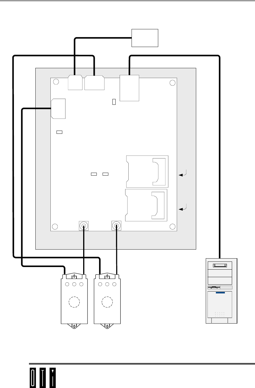
3 System Configuration
5VDC
LED
TR1
LED
TR2
LED
P8P9
ANT-CH1ANT-CH2
SAM 2
SAM1
SAM 4
(on back)
SAM 3
(on back)
USB
Good
LED
P2
P5
PWR
IN
LEDs &
Buzzer
ANT1
LEDs &
Buzzer
ANT2
USB
AntennaAntenna
Power
Supply
SCIBA2 Reader
HOST
LEDs cable
LEDs cable Coax
cable
Coax
cable
LEDsLEDs
Buzzer Buzzer
USB Cable
Power Cable
P4
P6
Figure 3-1: SCIBA2 System Configuration

SCIBA2 User & Installation Manual Version 1.00
System Configuration
page 3-5
3.1 SCIBA2 Reader
Enclosure ABS Plastic
Protection IP20
3.1.1 Standard Connectors
Antenna # 1 RF Connector P8
MCX type coax connector
Antenna #1 External LEDs connector P4
6-pin Molex connector pin-to-pin compatible with LEDs connector on
Antenna
1. Pin 1 – LED1
2. Pin 2 – LED2
3. Pin 3 – LED3
4. Pin 4 – Buzzer
5. Pin 5 – GND
6. Pin 6 – +5V
Antenna # 2 RF Connector P9
MCX type coax connector
Antenna #2 External LEDs connector P6
6-pin Molex connector pin-to-pin compatible with LEDs connector on
Antenna
1. Pin 1 – LED1
2. Pin 2 – LED2
3. Pin 3 – LED3
4. Pin 4 – Buzzer
5. Pin 5 – GND
6. Pin 6 – +5V
Power IN connector P5
4-pin reader power supply input connector
1. Pin 1 – Vin -
2. Pin 2 – Vin + (7.0 – 15VDC)
3. Pin 3 – GND
4. Pin 4 – Regulated 5VDC
USB connector P2
USB Device (B) connector
1. – VCC
2. – CD-
3. – CD+
4. – GND

SCIBA2 User & Installation Manual Version 1.00
System Configuration
page 3-6
3.1.2 Optional Connectors
External Buzzer connector P3
2-pin Molex Microfit connector
1. Pin 1 – GND/+5V
2. Pin 2 – Open collector output
COM1 RS232 connector P1
RJ45 connector.
1. Pin 4 – GND
2. Pin 5 – RXD
3. Pin 6 – TXD
External I/O connector P7 (Optional)
10-pin Molex connector
1. Pin 1 –GND
2. Pin 2 – +5V
3. Pin 3 – IN/OUT
4. Pin 4 – IN/OUT
5. Pin 5 – IN/OUT
6. Pin 6 – IN/OUT
7. Pin 7 – IN
8. Pin 8 – IN
9. Pin 9 – IN
10. Pin 10 – IN
Antenna Channel 1 connector P10 (Optional)
3-pin Molex connector
Antenna Channel 2 connector P11 (Optional)
3-pin Molex connector
CH2 RS232 connector P12 (Optional)
3-pin Molex connector
1. Pin 1 – GND
2. Pin 2 – RXD
3. Pin 3 – TXD
COM1 RS485 terminal TB1 (Optional)
Terminal block.
1. – D
2. – D*
3. – GND

SCIBA2 User & Installation Manual Version 1.00
System Configuration
page 3-7
3.1.3 LEDs
LED1
Green - USB link good
LED2
Red – user programmable
LED3
Red – user programmable
LED4
Red – user programmable
LED5
Red – 5V power
LED6
Green – channel 1 Antenna ON, optionally user programmable
LED7
Green – channel 2 Antenna ON, optionally user programmable
3.1.4 Jumpers
J1
Emergency jumper used to reset flash.
3.1.5 SAMs
SAM 1
SIM Connector on PCB front
SAM 2 (Optional)
SIM Connector on PCB front
SAM 3 (Optional)
SIM Connector on PCB back
SAM 4 (Optional)
SIM Connector on PCB back
SCIBA2 User & Installation Manual Version 1.00
System Configuration
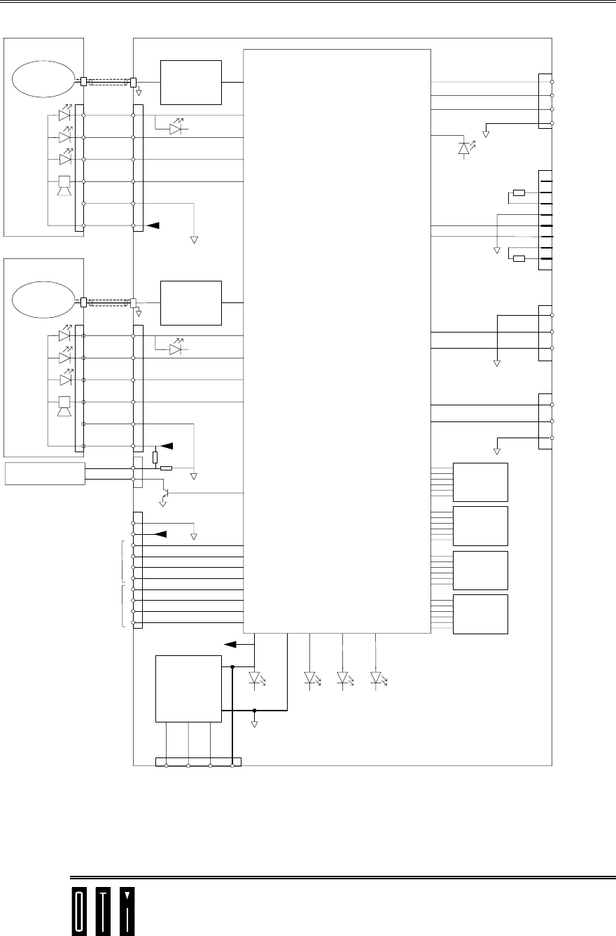
page 3-8
LED1
LED2
LED3
Buzzer
Antenna #1
Antenna
coil
+5V
LED1
LED2
LED3
Buzzer
Antenna #2
Antenna
coil RF
Channel #2
+5V
TR2
100mA Output
+5V
SAM
#4
Voltage
Regulator
+5V
V- V+ GND
VIN
7 - 15VDC
SAM
#3
SAM
#2
SAM
#1
1
2
3
4
5
6
2
3
4
5
6
1
1
2
3
4
5
6
1
2
3
4
5
6
1
2
3
4
5
6
7
8
9
10
1
2
Digital inputs/
outputs
Digital Inputs
Open collector
Programmable
LEDs
RF
Channel #1
TR1
5V
(REG)
1234
+5V
P5
P7
P3
P6
P4
P8
P9
Digital Section
SCIBA2
MCX
MCX
COM2
1
2
3
TB1
DT
DT*
GND
COM1
RS485
DTR
DSR
GND
RXD
TXD
CTS
RTS
1
2
3
4
5
6
7
8
P1
USB link good
1
2
3
P12
GND
RXD
TXD
RS232
1
2
3
P2
VCC
CD-
CD+
4GND
USB
RS232
COM1
Figure 3-2: SCIBA2 – Reader Block Diagram

SCIBA2 User & Installation Manual Version 1.00
System Configuration
page 3-9
3.2 Antenna
The SCIBA-2 is supplied with standard antennas with which the system was EMC certified.
The use of other antennas requires re-testing and certification.
Enclosure ABS Plastic
Protection IP__
The antenna is provided with two cable tails
1. Six-wire cable tail with Molex 6 pole connector connected to the antenna’s three
LEDs and buzzer
2. Coax cable tail with the MCX connector which is connected to the antenna’s RF
coil.
Important!
Use coax cable in length provided.
Do not shorten or lengthen coax cable.
3.3 Power Supply
Power supply voltage should be in the range of 7.0 to 15VDC.
If the power supply may provide current more than 5A a fuse of 4.5A should be used, if
the maximum power supply current less than 5A there are no special requirements.
Standard power adapter, mains/(9 to 12 V DC) is recommended for use:
9VDC or 12VDC 500mA
.

SCIBA2 User & Installation Manual Version 1.00
Installation Instructions
page 4-10
4 Installation Instructions
4.1 Reader Installation
Install the reader in a location where it will not be subjected to excessive heat, humidity or
vibration.
Heavy electrical equipment should not be installed close to the reader.
4.2 Antenna Installation
Mount antenna on non-metallic surface. Distance between antenna and closest metal surface
should be at least 30 millimeters.
Route antenna cables to reader in protective conduit.

SCIBA2 User & Installation Manual Version 1.00
Flash Memory Programming
page 5-11
5 Flash Memory Programming
5.1 Introduction
The SCIBA2 reader’s program is stored in its non-volatile Flash Memory.
Application versions and updates to the SCIBA2 reader’s program may be
written only at OTI.
The application versions and updates can be programmed into the SCIBA2
reader’s Flash memory by the customer through use of the Flash Memory
Programmer software, described in the following paragraphs.
5.2 PC requirements
Flash Memory Programmer software runs on Windows 95 or
Windows NT 32bit operating systems.
PC should be at least a 486 DX2.
Program loading time depends on the speed of PC.
5.3 Programmer Software Installation
1. Run the setup.exe file from CD.
2. Follow the instructions on the PC screen.
5.4 Hardware Setup
1. Connect RS232 cable between PC and SCI interface.
Note: DTR and DSR as well as CTS and RTS in the PC connector
should be shorted. For 25-pin D type connector, short between 4 & 5
and between 6 & 20.
For 9-pin D type connector, short between 4 & 6 and between 7 & 8.
2. Apply power to the reader

SCIBA2 User & Installation Manual Version 1.00
Flash Memory Programming
page 5-12
5.5 Programming
5.5.1 Flash Memory Files
The flash memory files, written at OTI can be loaded into the PC from CD
or through the Internet.
The prefix of the flash memory files is SCI5, followed by a four-character
application code, followed by the date.
5.5.2 Programming Procedure
1. Run the Flash Programmer software
2. Choose the communication port
3. Press the “Load” button.
A dialogue window opens,
4. Select the file to be programmed into the SCIBA2 reader.
The selected file is validated as an SCI5flash memory file.
5. Press the “Program” button.
The programmer will start programming the selected file into the
flash memory.
If the SCIBA2 reader is already programmed, the programmer will
issue a warning and wait for an approval to continue by pressing the
“yes” button
The system automatically finds and switches to the fastest Baud rate
possible.
6. After programming the file into the flash memory, the programmed
file is verified, and a “ valid version” flag in the SCIBA2 reader’s
memory is set.
7. The SCIBA2 reader is ready to operate with the new program file.
5.6 Help
A comprehensive Help section provides the user with detailed explanations
regarding the operation of the Flash Memory Programmer software.