One World Technologies GD200 GDO200 main unit User Manual 1
One World Technologies, Inc. GDO200 main unit Users Manual 1
UserManual.wiki
>
One World Technologies
>
GD200 User Manual
>
Users Manual 1
Contents
1.
Users Manual 1
2.
Users Manual 2
3.
Users Manual 3
Users Manual 1
Navigation menu
Upload a User Manual
Namespaces
Wiki Guide
HTML
PDF
Info
Views
User Manual
Discussion / Help
Navigation
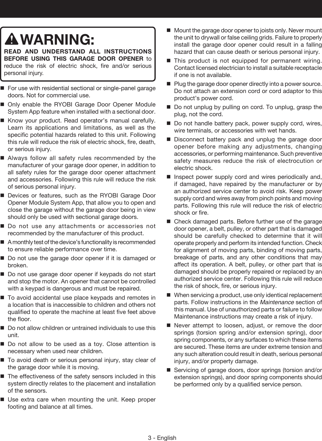
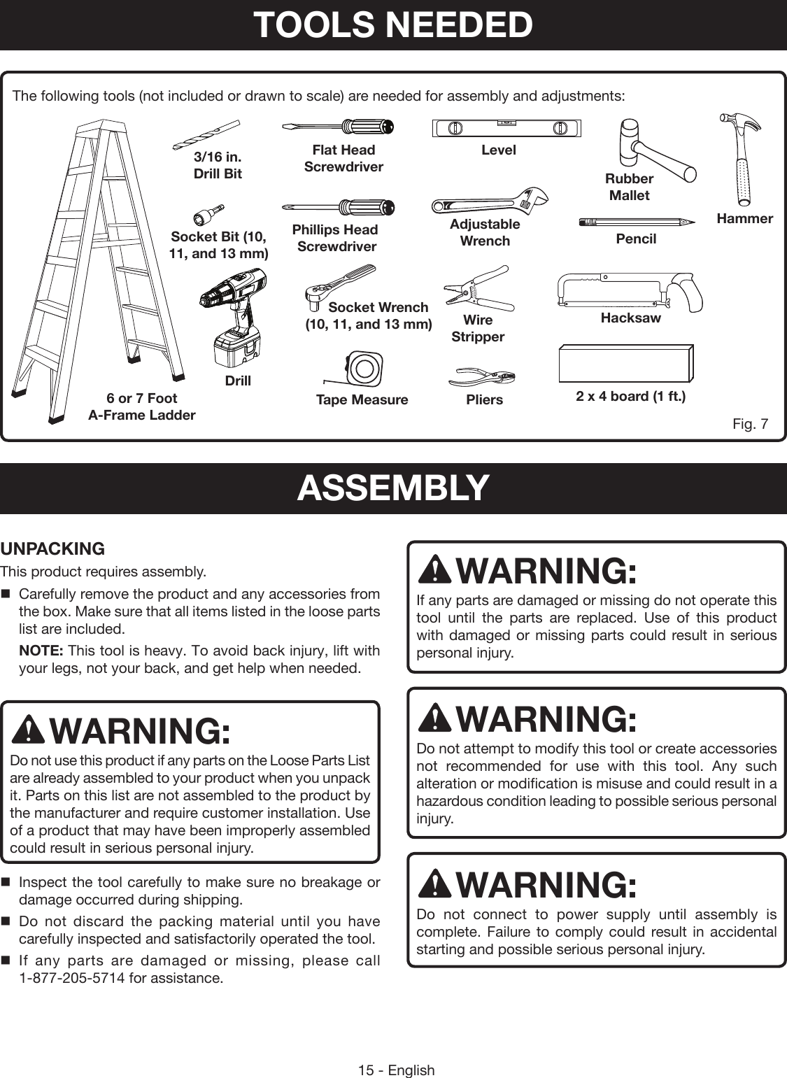
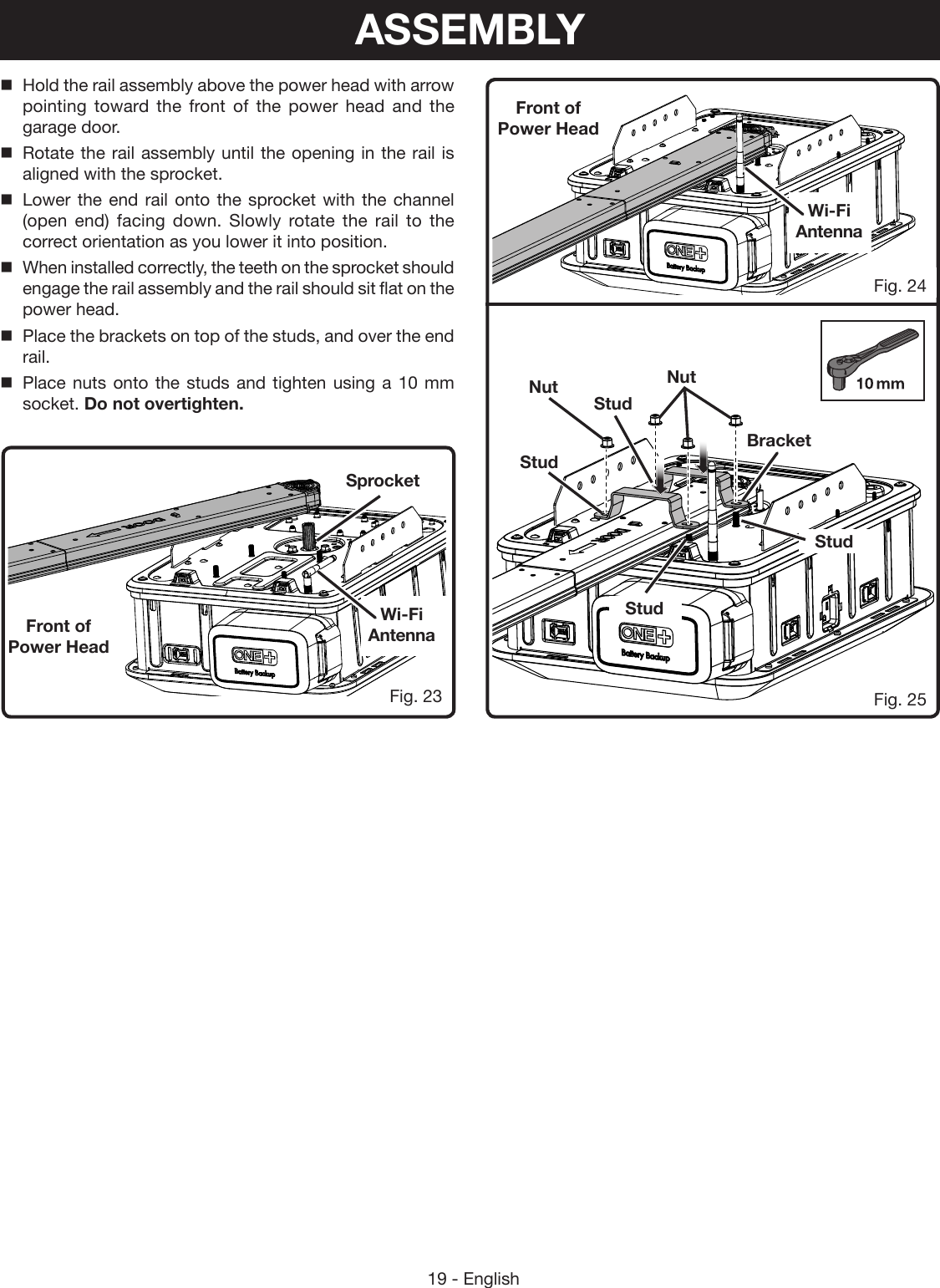
![18 - EnglishFig. 20Fig. 19TightenLoosen3/8 in. to 1/2 in.Base of the nutEdge of the braceRail EdgeCENTER OF RAIL ASSEMBLYATTACHING RAIL ASSEMBLY TO POWER HEADSee Figures 22 - 25.Locate the following items:Power HeadBracket (2)Nut (M6) [4]SprocketRail AssemblyPlace the power head on a towel or the packaging material with the light cover facing down.Remove the tape securing the Wi-Fi antenna and raise it to an upright position to ensure the best Wi-Fi signal. Place the sprocket onto the motor shaft with the round side of the sprocket facing up.Fig. 21Fig. 22Belt1/8 in. GapSprocketRound SideShaftADJUSTING THE BELT TENSIONSee Figures 18 - 21.Using a 13 mm socket, turn the tension nut clockwise to tighten the belt and counter-clockwise to loosen it. Adjust the nut until there is approximately 3/8 to 1/2 in. of exposed thread showing above it or until the base of the nut is aligned with the edge of the brace.When properly tensioned, there should be about a 1/8 in. gap between the belt and the edges of the intermediate rail near the center of the rail assembly.ASSEMBLY](https://usermanual.wiki/One-World-Technologies/GD200.Users-Manual-1/User-Guide-2906779-Page-18.png)

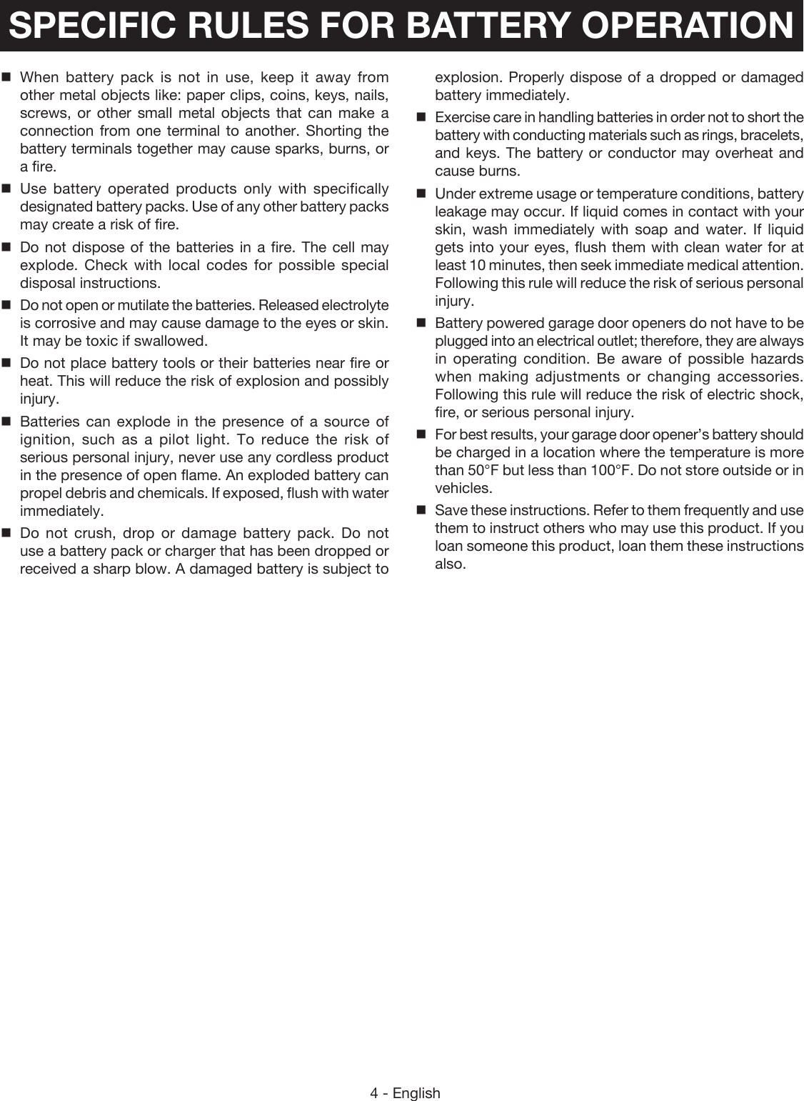
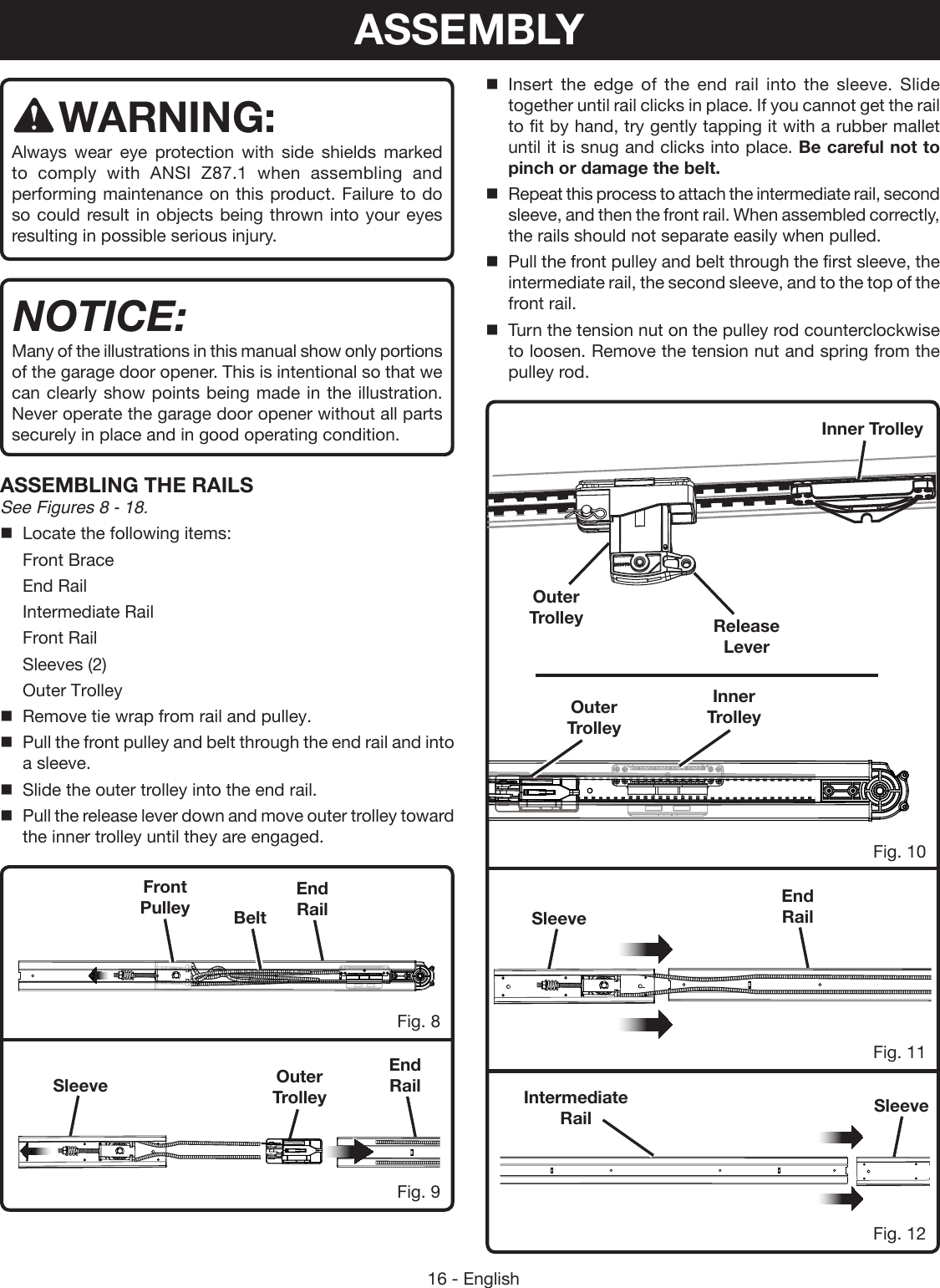
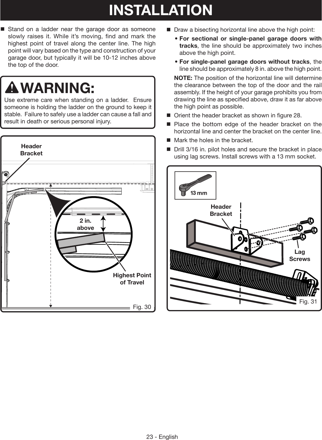
![22 - EnglishFig. 29LevelCenter LineHorizontal Line2 x 42 x 4 board. The 2 x 4 board can be installed between two studs or into masonry using lag screws and concrete anchors (not supplied).Locate the following items:Header BracketLag Screw (M8 x 2 in.) [4]To install the bracket to the header wall:Lower the garage door completely.Using a pencil and a level, draw a vertical line in the center of the top portion of the garage door.Continue drawing the center line from the door to the header wall. Extend the line to about a foot above the garage door or as far as possible. INSTALLING THE HEADER BRACKET See Figures 29 - 31.WARNING:To avoid serious personal injury, attach header bracket to sound structural support on header wall. NEVER install the header bracket into weak surfaces such as drywall that can cause the header bracket to fall. WARNING:ALWAYS use lag screws and concrete anchors (not included) when installing the header bracket or 2x4 into concrete, brick, or other masonry. Failure to properly install the header bracket and associated hardware can result in a falling object hazard and result in death or serious personal injury.WARNING:Only install screws, bolts, anchors, and other hardware into sound structural supports in areas where no electrical wires, utility cables, pipes, or other obstructions are located. Contact your local utility company or a qualified electrician if you are unsure. Ensure all hardware components are securely installed to prevent falling objects. Failure to follow these instructions can result in death, electrical shock, or other serious personal injury.Always install the header bracket onto a sturdy surface. The force required to raise and lower the garage door could pull the bracket and mounting hardware out of weak surfaces such as drywall. For some installations, it may be neccesary to create a suitable location for the bracket by installing a INSTALLATION](https://usermanual.wiki/One-World-Technologies/GD200.Users-Manual-1/User-Guide-2906779-Page-22.png)
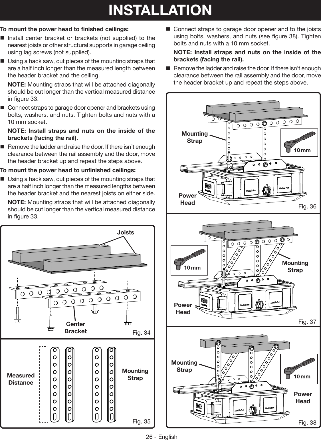
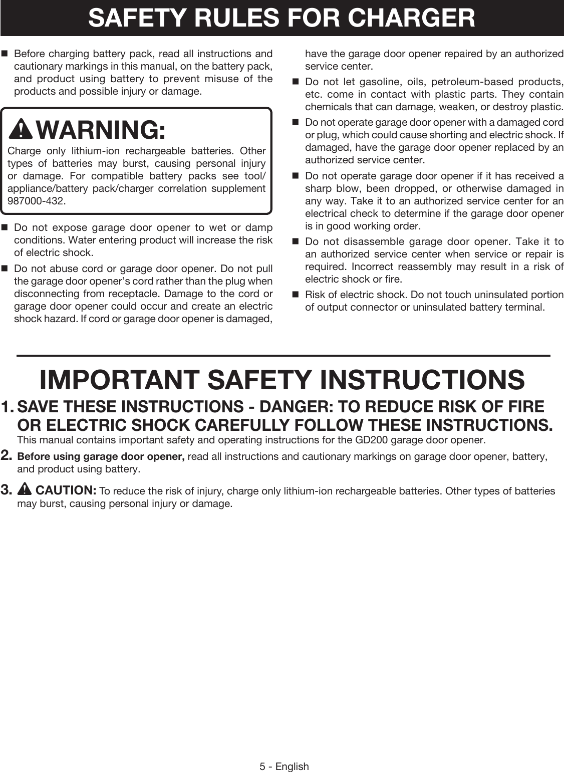
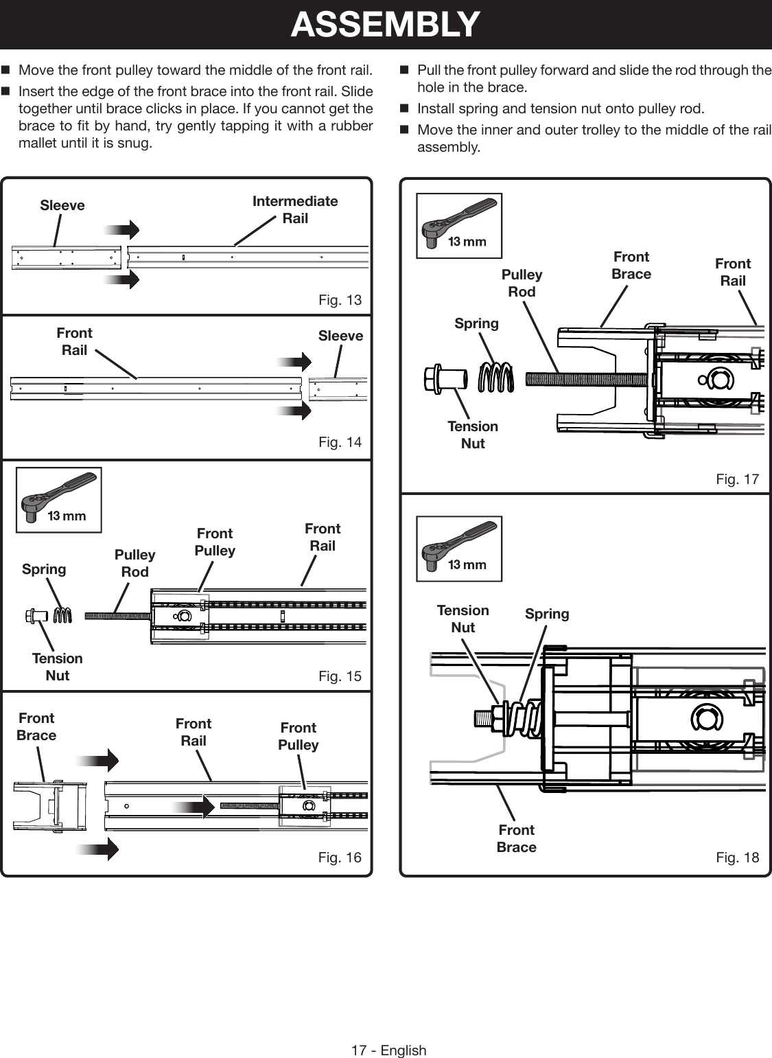
![25 - EnglishPower HeadMOUNTING THE POWER HEAD TO THE CEILING See Figures 33 - 38.WARNING:Mount garage door opener to sound structural support on ceiling. NEVER mount the garage door to drywall or false ceiling grids. ALWAYS use concrete anchors when installing brackets into concrete, brick, or other masonry. Failure to properly mount the power head can cause it to fall and could result in death, serious personal injury, or property damage.Locate the following items:Mounting Strap (2)Bolt (M6 x 3/4 in.) [6]Washer (M6) [6]Nut (M6) [6]Lower the garage door completely.Measure the space between the header bracket and the ceiling.NOTE: For unfinished ceilings, measure the space between the header bracket and the nearest joists on either side.Carefully lift the power head and place it on top of a ladder.Move the power head until it is aligned with the header bracket and the rail assembly is over the center line of the door.Pull the trolley release lever down and slide outer trolley completely toward the power head.NOTE: The proper configuration and placement of brackets and mounting straps will vary based on the design and construction of your garage ceiling. Figures 34 - 38 are meant to serve as examples but your setup may vary. Header BracketCeilingFig. 33Measured DistanceOuter TrolleyINSTALLATION](https://usermanual.wiki/One-World-Technologies/GD200.Users-Manual-1/User-Guide-2906779-Page-25.png)