Onkyo Home Entertainment MHPAV1 Base Station of Wireless Headphone User Manual MHK AV1 MANUAL
Onkyo Corporation Base Station of Wireless Headphone MHK AV1 MANUAL
UserManual.wiki
>
Onkyo Home Entertainment
>
MHPAV1 User Manual
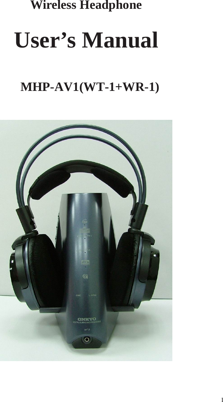
Users Manual
Navigation menu
Upload a User Manual
Namespaces
Wiki Guide
HTML
PDF
Info
Views
User Manual
Discussion / Help
Navigation