OpenCell 0012TC19001 PCS-over-Cable Base Station User Manual 1000070A
OpenCell Corp PCS-over-Cable Base Station 1000070A
UserManual.wiki
>
OpenCell
>
0012TC19001 User Manual
Exhibit D Users Manual 2 1033 c 3
Navigation menu
Upload a User Manual
Namespaces
Wiki Guide
HTML
PDF
Info
Views
User Manual
Discussion / Help
Navigation
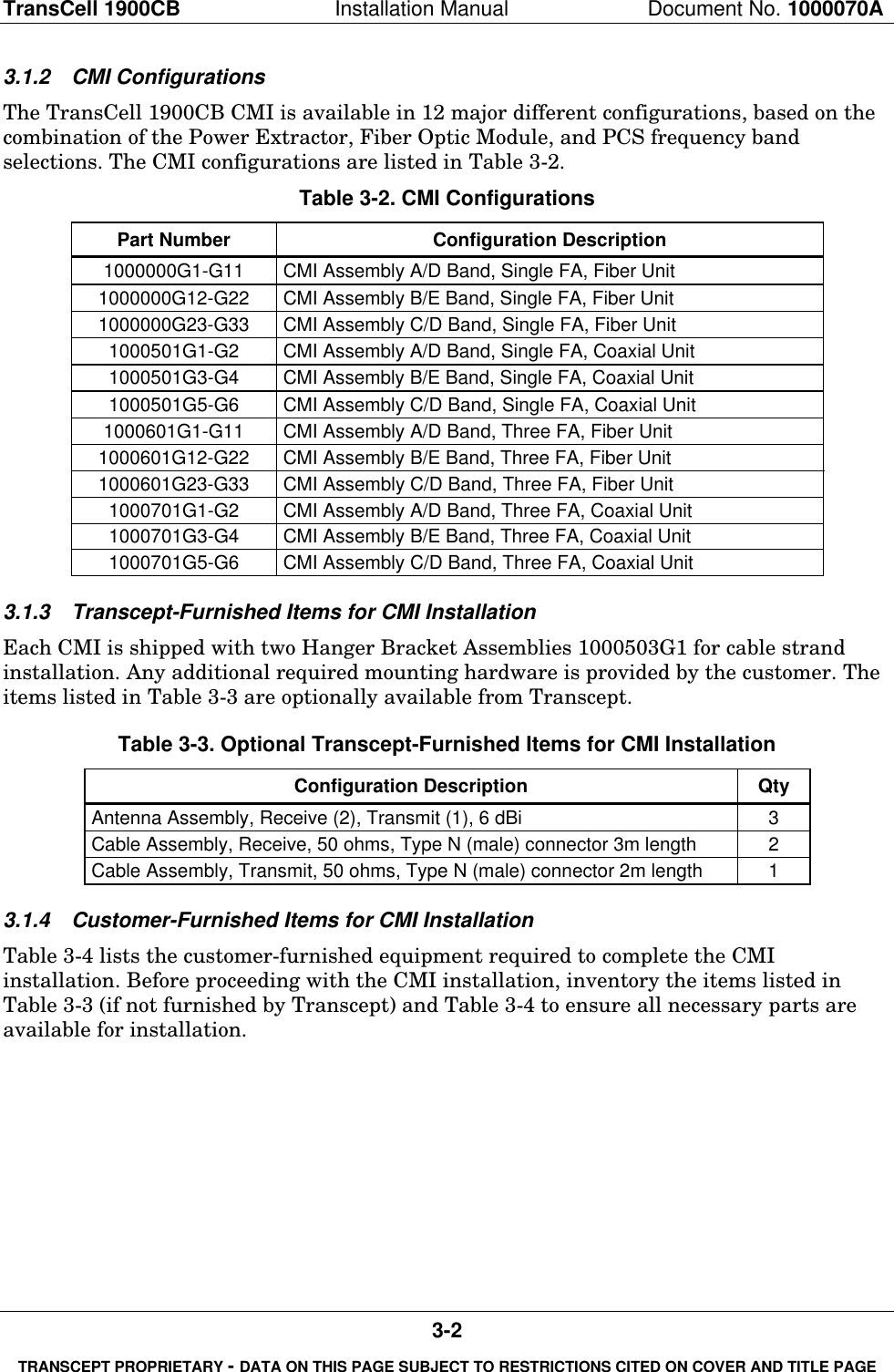
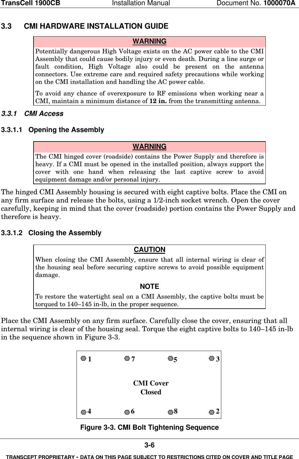
![TransCell 1900CB Installation Manual Document No. 1000070A1-3TRANSCEPT PROPRIETARY - DATA ON THIS PAGE SUBJECT TO RESTRICTIONS CITED ON COVER AND TITLE PAGE1.2.3 Notation Conventions in this ManualThis manual assumes that the user has a basic knowledge of the Windows NToperatingsystem. Several typographic conventions and standard Windows NT terms are used inthis manual when discussing the TransCell Network Manager software. They are asfollows:Mouse Commands - The TransCell Network Manager software uses only the left mousebutton:♦ “click” - press and release the left mouse button♦ “double-click” - press and release left mouse button twice in quick successionMenu Commands - Menu commands are bolded with each command level separated fromthe previous one by a slash (/) mark, e.g., “Select Privileges/Modify Privileges.”Button Names – Command button names in dialogs are underlined, e.g., “To confirmselection, click OK.”Key Names - Key names are spelled out and appear in small, bold capital letters, e.g.ENTER, ESCAPE, AND CONTROL.Dialogs and Messages - Dialog and message titles appear in all upper case (capital) letters,and generally the name is referenced exactly as shown on the title bar, e.g., the PCSFREQUENCY dialog. However, in cases where the dialog title varies according to privilegelevel, enclosure, or sector, the title is shortened to exclude this variable information unlessthe variable is important. If a dialog title is referenced that includes a specific HIC or CMInumber, the number is represented by the bracketed letter n: e.g., CMI CONTROLPANEL: ALPHA SECTOR, CMI [n].Dialog Options - Dialog options (text boxes and radio buttons) are shown in italics, e.g.,“Type in the desired PCS Frequency.” All instructions to “select” or “choose” an optionimply clicking on that option, although options can be selected via the keyboard as well.Keyboard Input - Instructions for keyboard entries start with “Type in...”, and anythingthat should be typed in verbatim is shown in a contrasting font. For example, “Type inconfig01.dtb in the File Name box.”Displayed Text - Text displayed in a dialog box is shown in another contrasting font, e.g.,“The CONFIGURATION OPTIONS dialog displays the query “Do you Want To Restorea Pre-existing Configuration?”.1.3 REFERENCE DOCUMENTATION♦ Hub Control Unit (HCU)-associated vendor hardware/software documentation(Computer, Monitor, Watchdog Timer, etc.) Transcept Document No. 1000015P1♦ TransCell 1900CB System Acceptance Test Procedure Requirements, TransceptDocument No. 1000095♦ Mobile Station-Base Station Compatibility Std for Wideband Spread SpectrumCellular Systems, TIA/EIA-95-B](https://usermanual.wiki/OpenCell/0012TC19001/User-Guide-132474-Page-12.png)

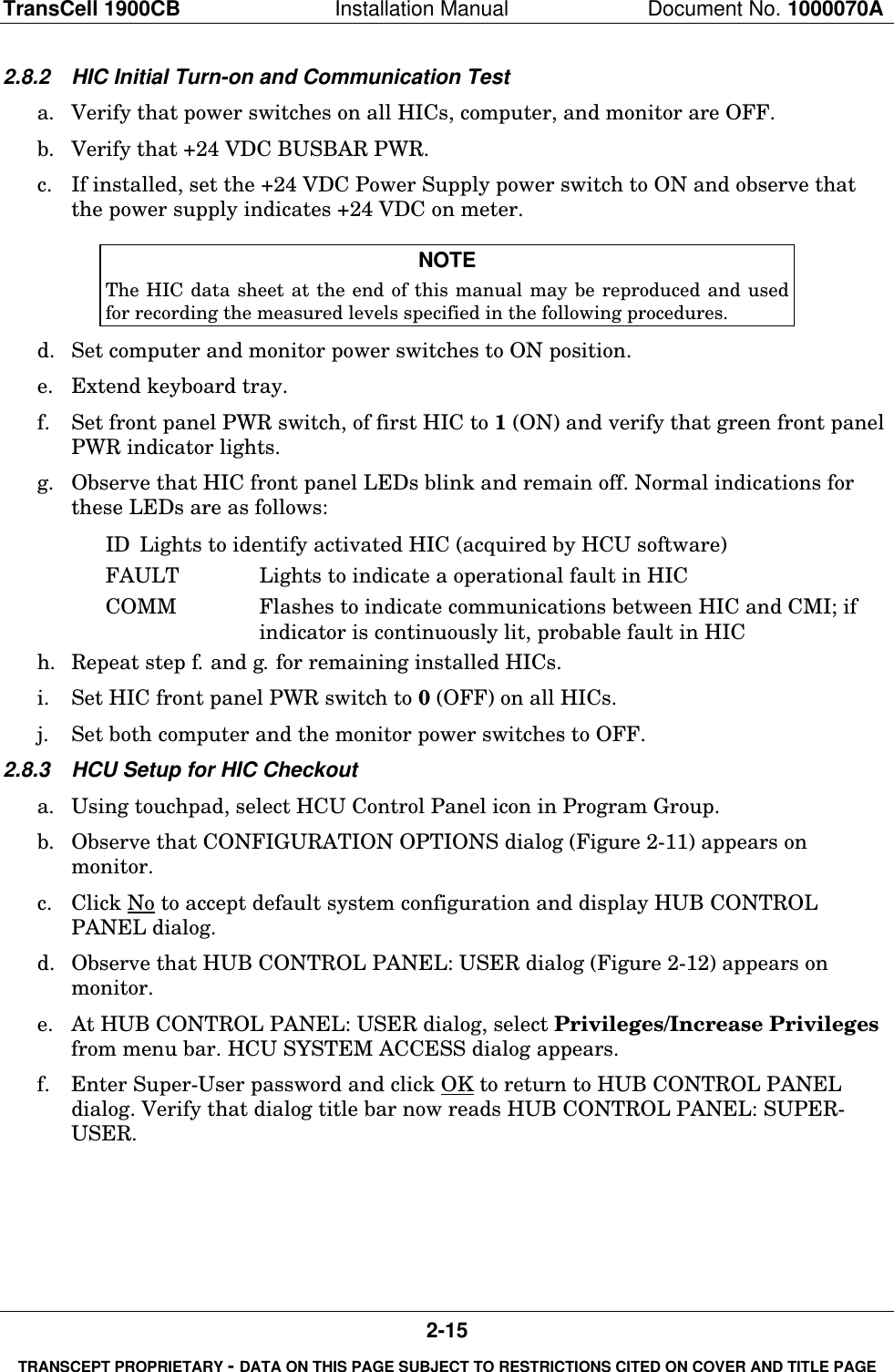
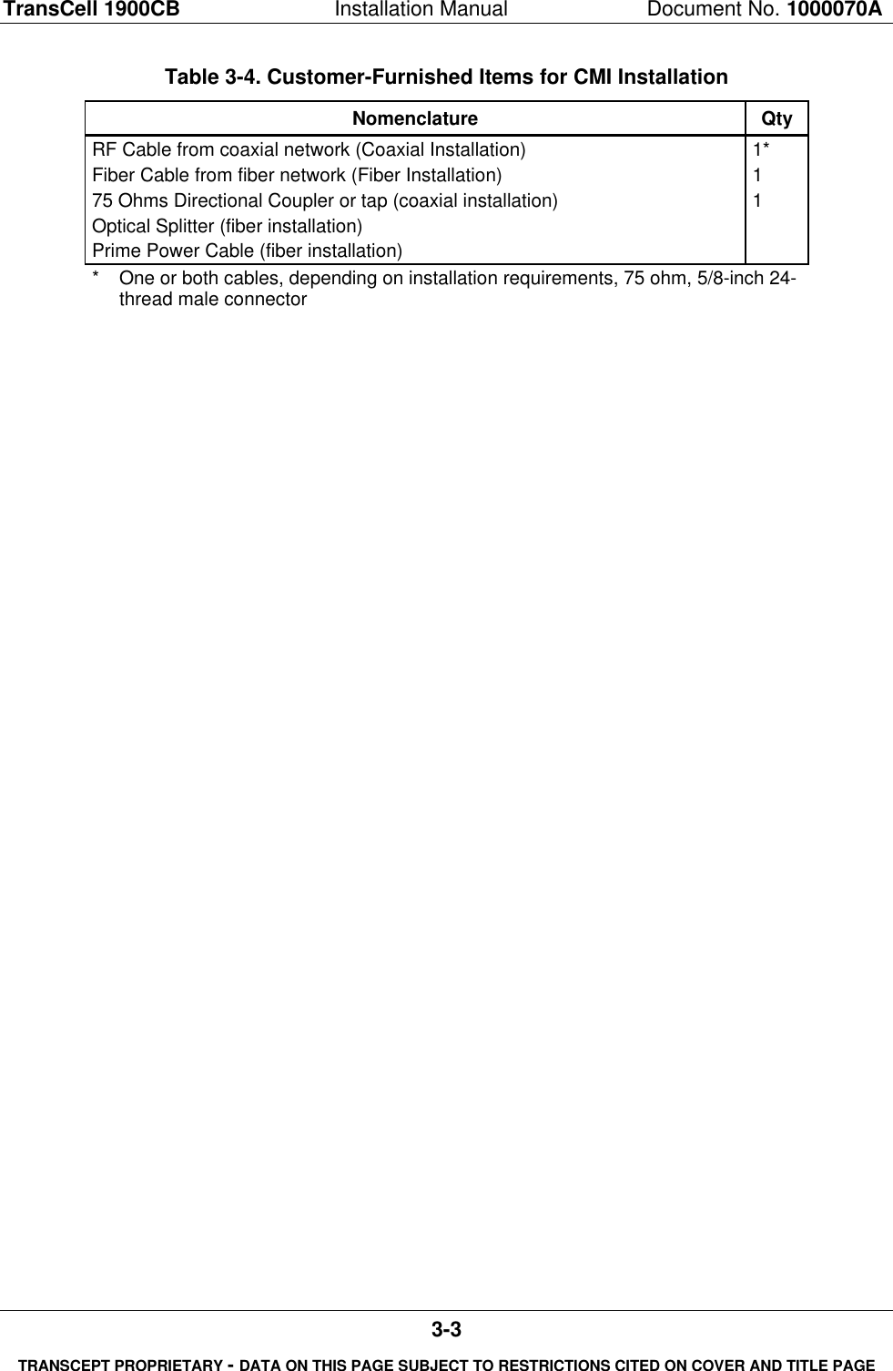
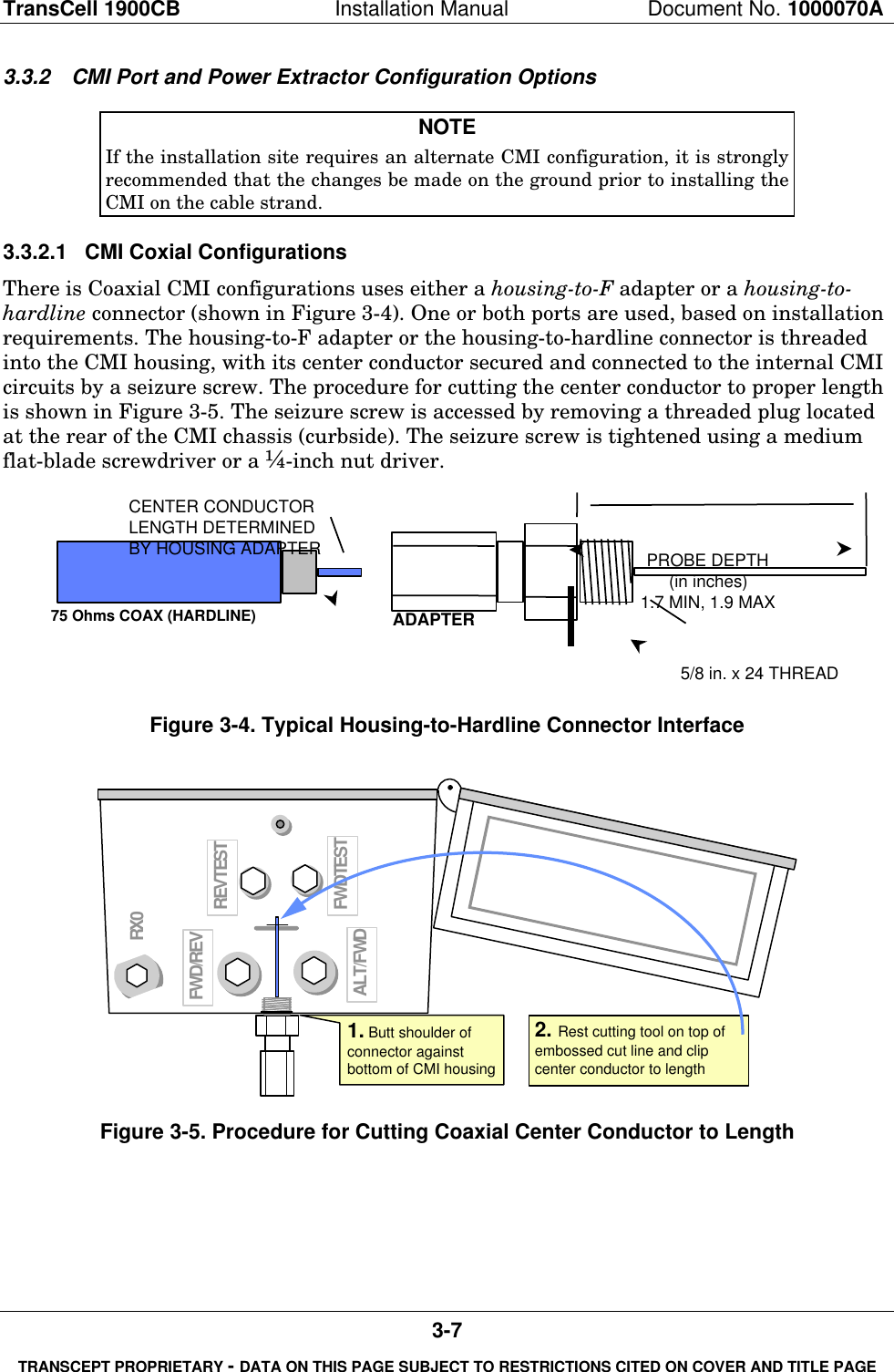
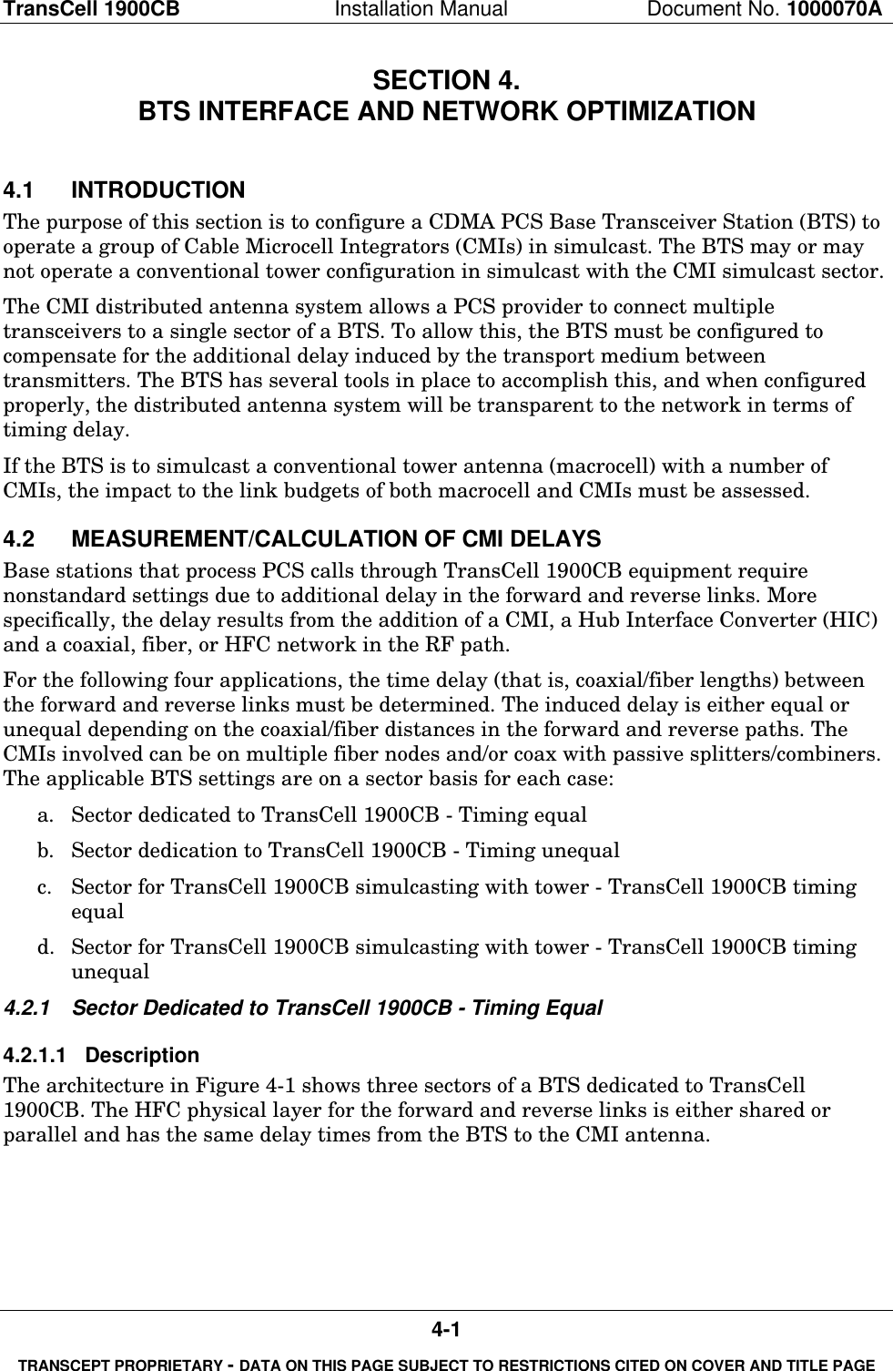
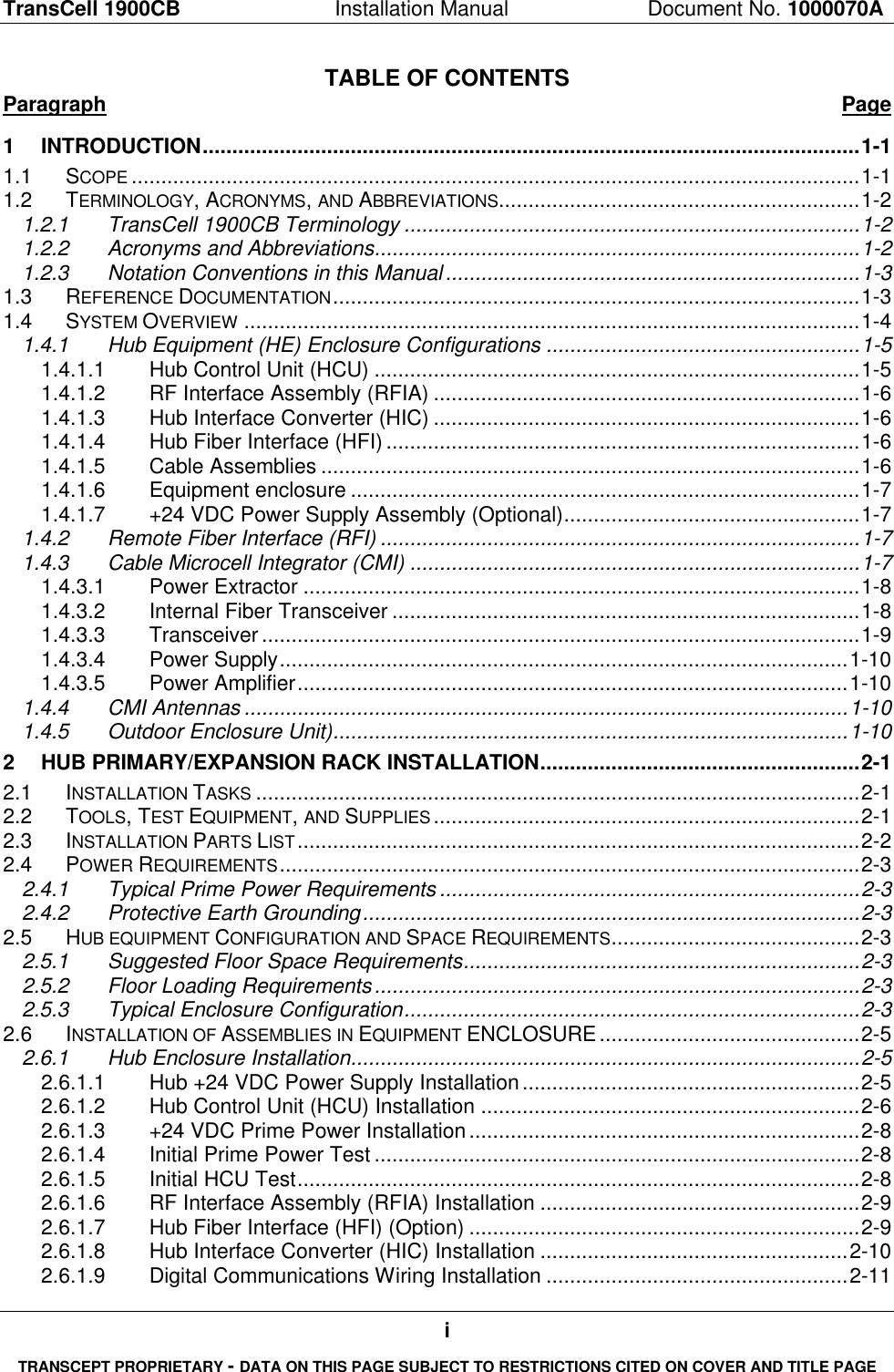
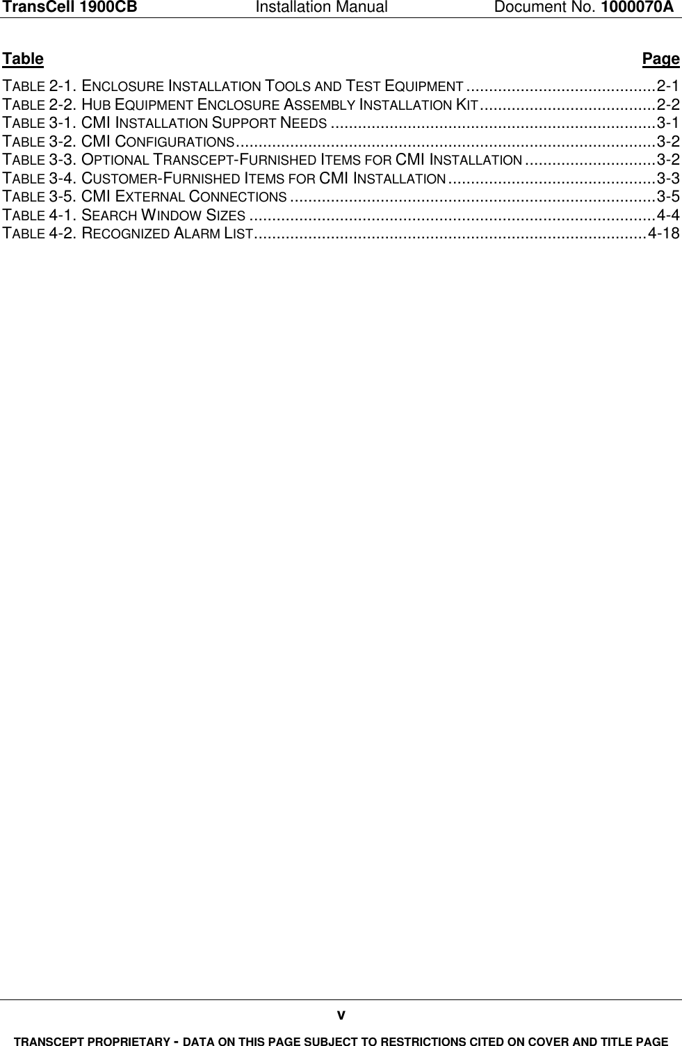
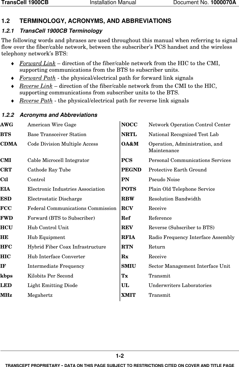
![TransCell 1900CB Installation Manual Document No. 1000070A4-2TRANSCEPT PROPRIETARY - DATA ON THIS PAGE SUBJECT TO RESTRICTIONS CITED ON COVER AND TITLE PAGEBTSγ DIV Rxγ XMIT & PRI RxForwardSplitReverseCombineandSplitHICαβγDuplexerDuplexerDuplexerα XMIT & PRI Rxβ XMIT & PRI Rxβ DIV Rxα DIV Rx(α,β, γ)FIBERNODESFiber OpticNetworkRxdRxpTxCOAXIALCABLECMIFIBERHUBRxdRxpTxCOAXIALCABLECMI(α,β, γ)RxdRxpTxCOAXIALCABLECMIFigure 4-1. Sector Dedicated to TransCell 1900CB with Equal Timing LinksThe delay added by the CMI and the HIC is the same for the forward link as it is for thereverse link. Since timing is equalized on the network and TransCell 1900CB equipment,and all PCS communications to the wireless handset are conducted through the CMIs, theBTS does not have to account for any differential timing on the forward and reverse linksother than that internal to itself.4.2.1.2 Basic BTS Settings for Dedicated Sector with Equal TimingFor the dedicated sector with equal timing, two TIA/EIA-95-B settings must be taken intoaccount, time reference and search window size. The BTS sets the search window in whichthe mobile unit searches for usable multipath components of the set of appropriate pilotsignals. The following procedures are recommended for determining the setting of thesetwo parameters.Regarding the time reference, section 6.1.5.1 of TIA/EIA-95-B states that the personalstation time reference “…shall be within ± 1 µs of the time of occurrence of the earliestmultipath component being used…” This establishes a common reference for system timewhen searching for multiple BTS pilot signals.For a dedicated sector implementation of TransCell 1900CB, the earliest multipathcomponent in the reverse link would typically appear at the antenna of the CMI that hasthe least amount of delay to the base station. To determine which CMI this is, the delaybetween each CMI antenna and the BTS input must be determined, either by measuring orcalculating the delay to each CMI antenna. The delay calculation or measurement is madein a single direction if the timing in the dedicated sector implementation is equal in eitherdirection. To calculate the delay to a CMI antenna, the following formula is employed:DTOTAL = DCMI/HIC + DFIBER + DCOAX + DLINE AMP [1]](https://usermanual.wiki/OpenCell/0012TC19001/User-Guide-132474-Page-66.png)
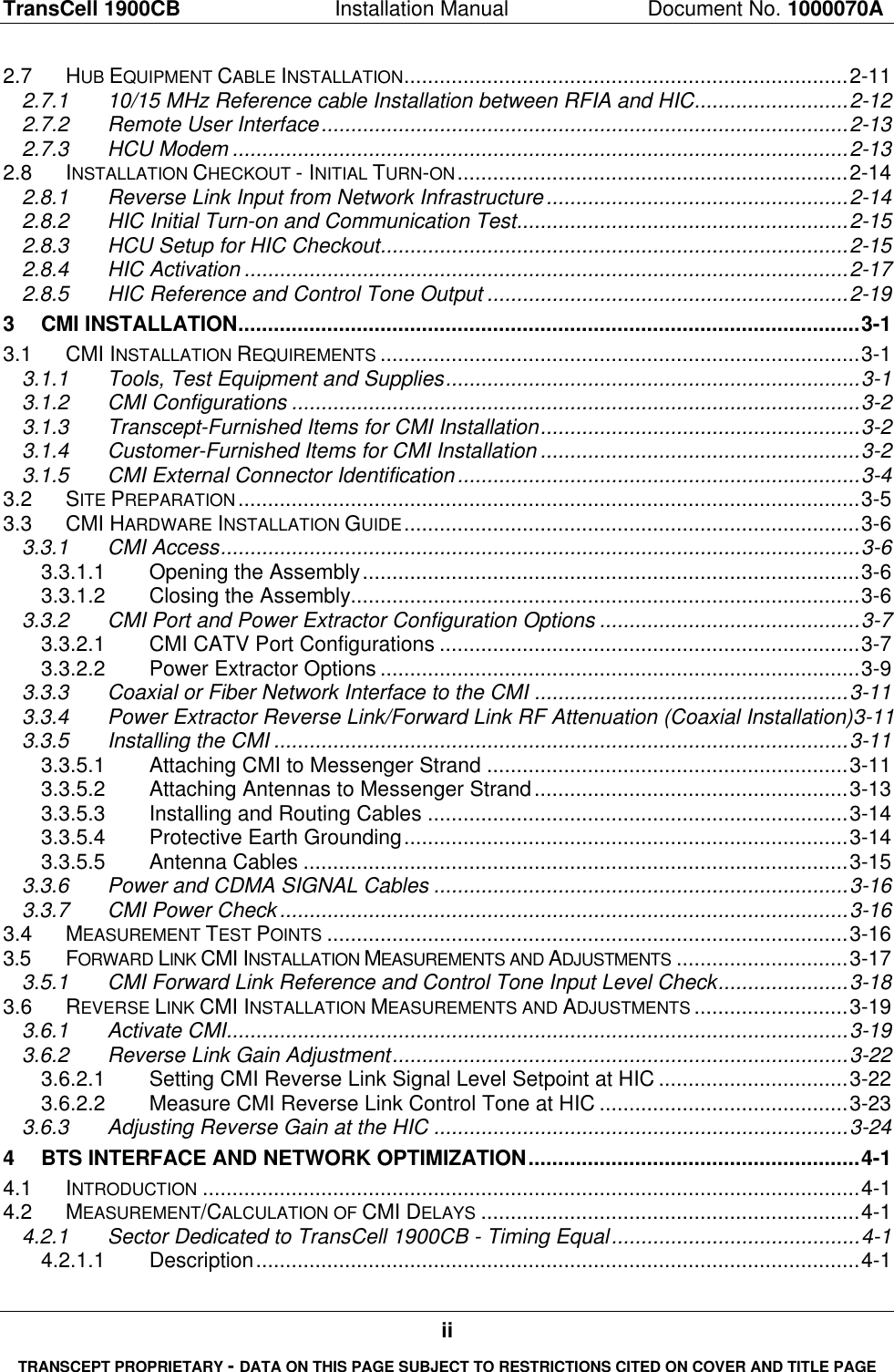
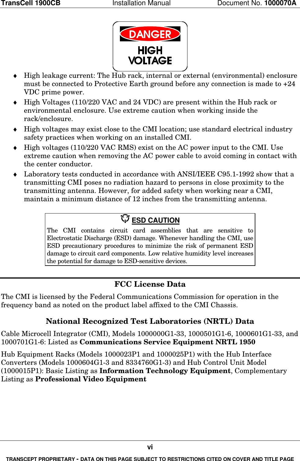
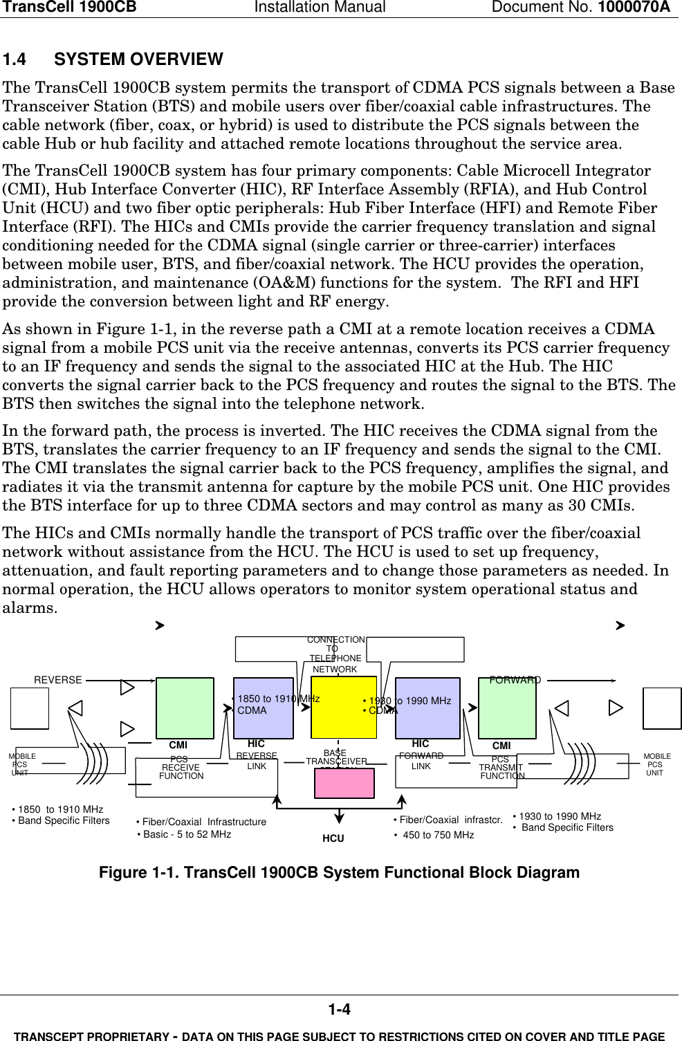
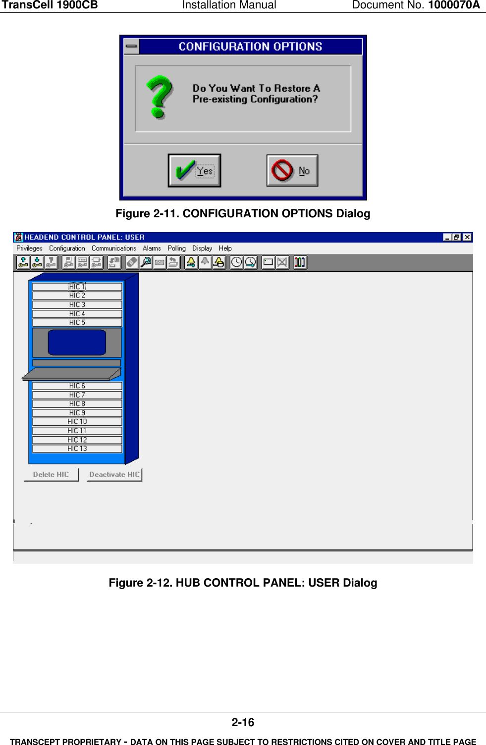
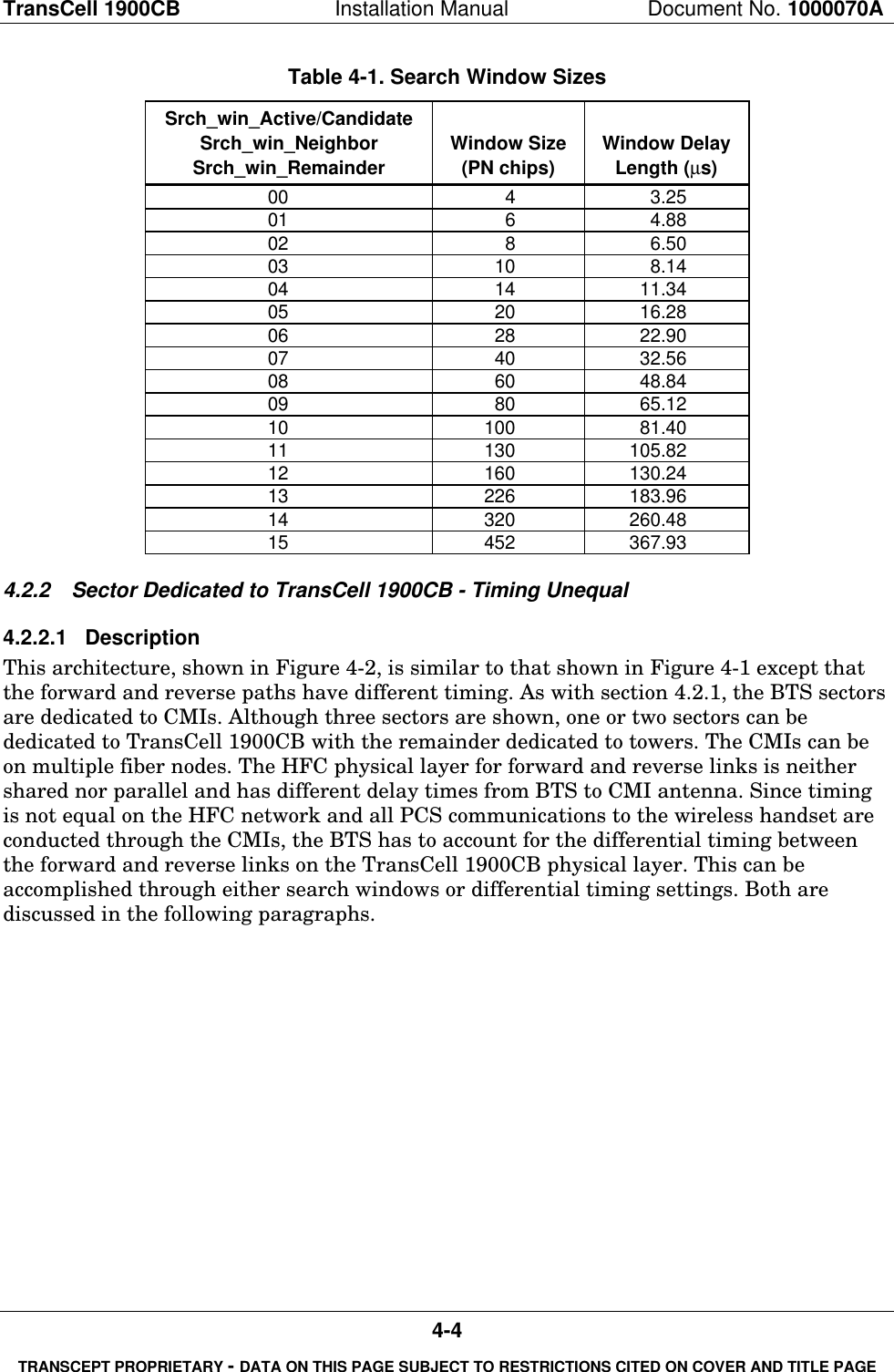
![TransCell 1900CB Installation Manual Document No. 1000070A4-3TRANSCEPT PROPRIETARY - DATA ON THIS PAGE SUBJECT TO RESTRICTIONS CITED ON COVER AND TITLE PAGEwhere: DCMI/HIC is the group delay in one direction of the CMI and the HIC = 12 µsDFIBER is the fiber delay at 5 µs/km of fiber (2.04 x 10⁸ m/s). Actual value can beobtained from fiber/cable specification sheets. It will be slightly different for thedifferent types of fiber or coaxial cable.DCOAX is the coaxial delay at 3.8 µs/km (2.74 x 10⁸ m/s). Actual value can beobtained from fiber/cable specification sheets. It will be slightly different for thedifferent types of fiber or coaxial cable.DLINE AMP is the delay added by all the line amps = 10 ns x no. of line amps(actual value can be obtained from amplifier manufacturer or specificationsheets)Once all the calculations have been made, the lowest delay value is then used for the timereference setting on the BTS. This will move 0-system time out to the CMI antenna that isnearest timewise. The calculated or measured value should be added to the default valuefor both “Tx_offset” and Rx_offset”.NOTEFor the time reference calculation, DAIR is 0 for a handset within 25 feet of thenearest (timewise) CMI antenna.The second setting that must be adjusted for TransCell 1900CB is the search window size.This again is caused by the delay inherent with TransCell 1900CB. The settings affect theactive search window, the neighbor search window, and the remainder search window, ifactive. Section 6.6.6.2.1 of TIA/EIA-95-B defines the establishment of search windows anddetails the available base station settings and the resultant window sizes. TIA/EIA-95-Bstates that: “The search window size for each pilot in the Active Set and the Candidate Setshall be the number of PN chips specified in Table 6.6.6.2.1-1 with the window centeredaround the earliest arriving multipath component of the pilot.”The window size determines the number of chips off of center that the handset searcheswhen looking for PN offsets (set of pilot signals). This should be sized according to theexpected delay. The same holds true for the neighbor list and the remainder list. Table 4-1lists the window size settings in Table 6.6.6.2.1-1 of TIA/EIA-95-B along with theequivalent delay length.For the dedicated sector with equal timing, the search window setting is selected fromTable 4-1 after calculating, with Equation [1] above, the delay for both the most delayedCMI and the least delayed CMI in the sector and calculating the differential. This then isthe range through which the search window must repeatedly pass to pick up all CMIs inthe sector. Equation [2] determines the search window size. The search window is centeredon the CMI antenna that is nearest timewise. This calculation is made with a maximumover-air propagation delay of 5.1 µs (1.5 km) to the most delayed CMI and a minimum over-air delay of 0 µs to the least delayed CMI (the CMI whose nearest antenna is 0 system timeset point). Hence the search window size is calculated as shown in Equation [2] in terms ofµs and Table 4-1 determines the setting.SRCH_WIN_A = (DTOTAL, MAX [DAIR @1.5 km] - DTOTAL, MIN [DAIR @0 km])/2 [2]Note: DAIR is always zero.](https://usermanual.wiki/OpenCell/0012TC19001/User-Guide-132474-Page-67.png)
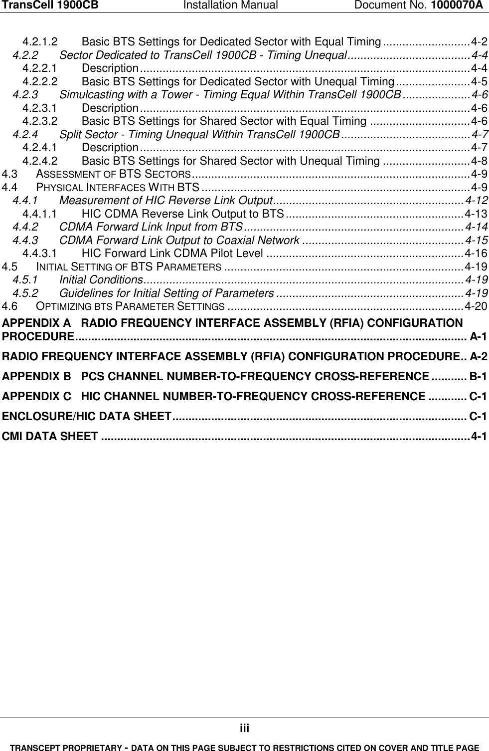
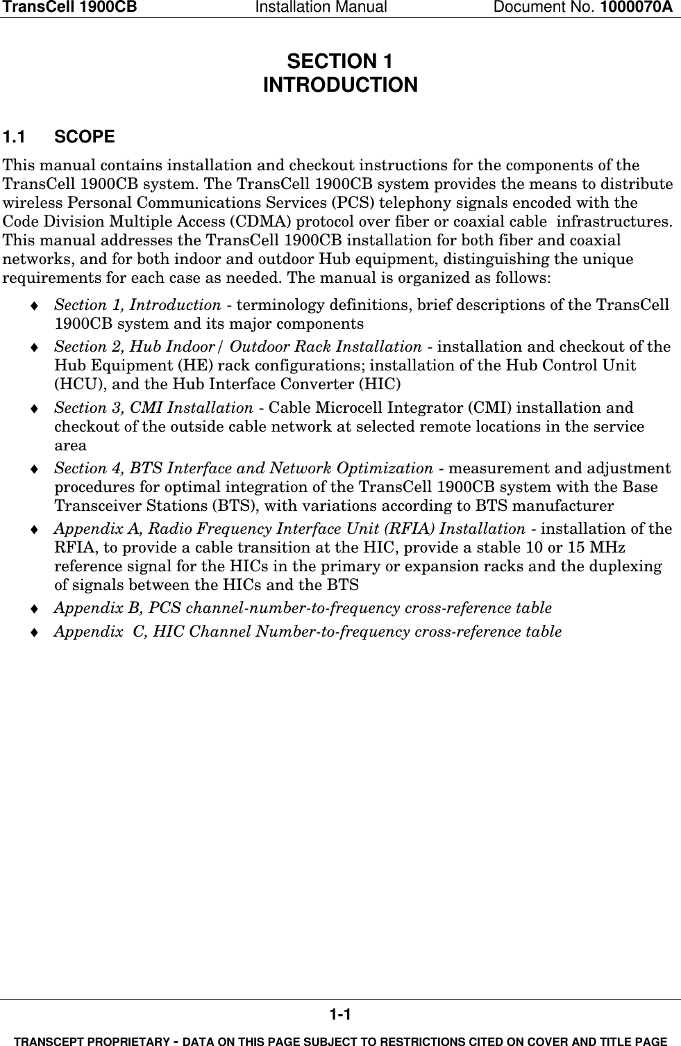
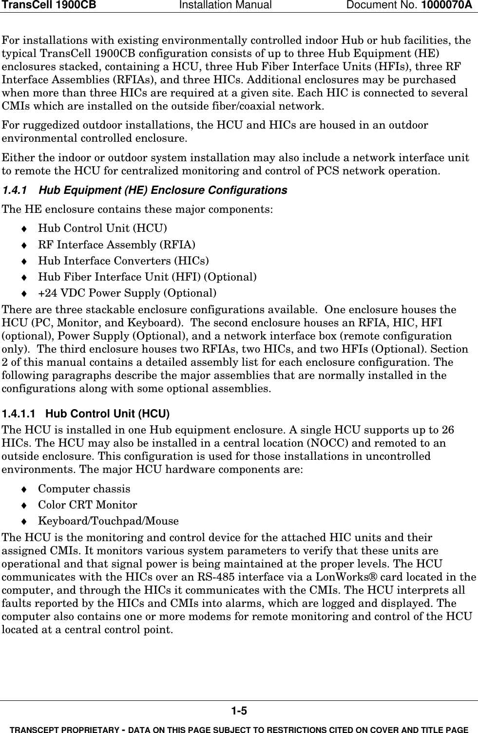
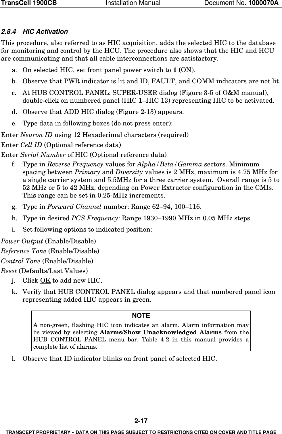
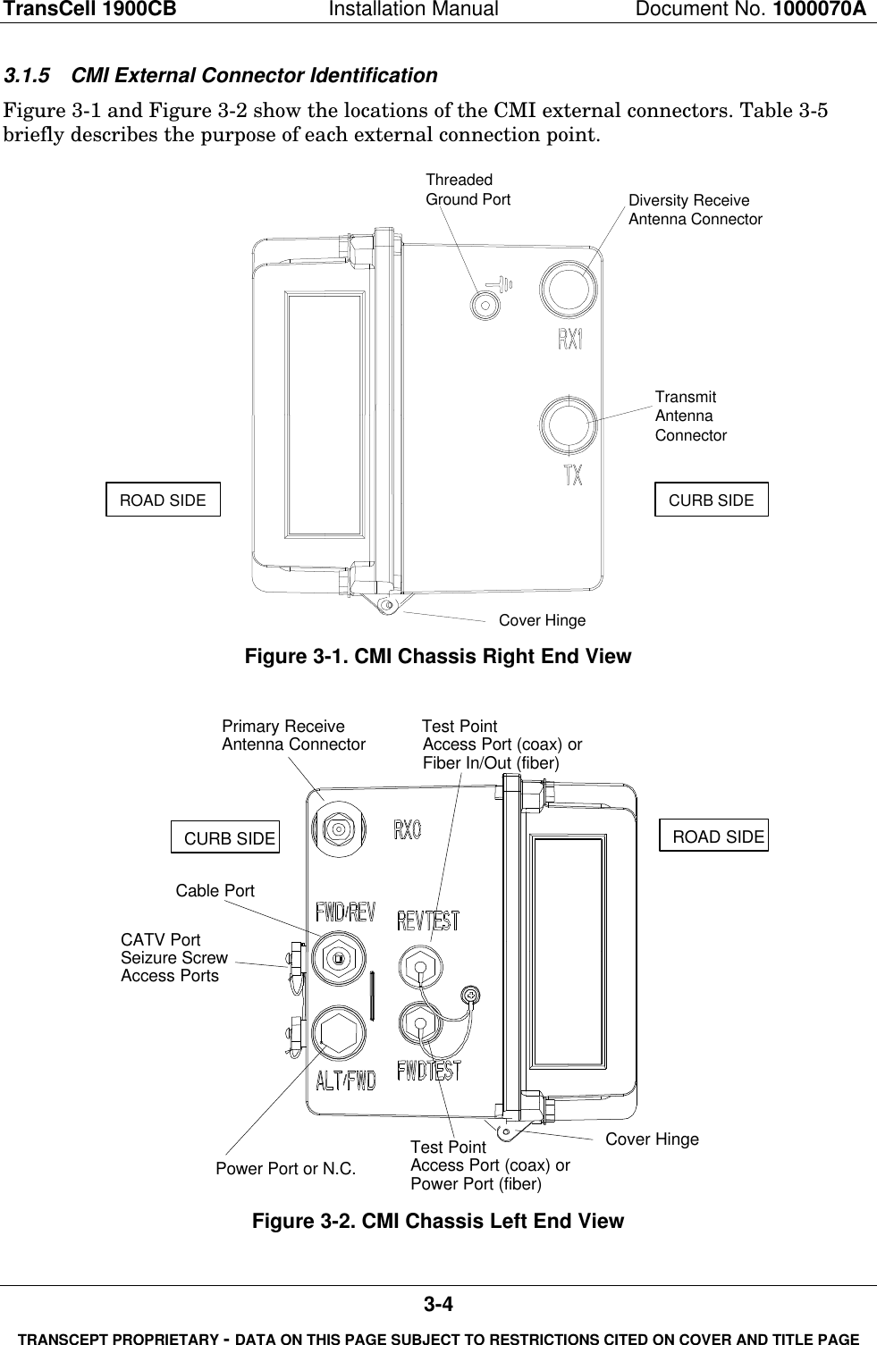
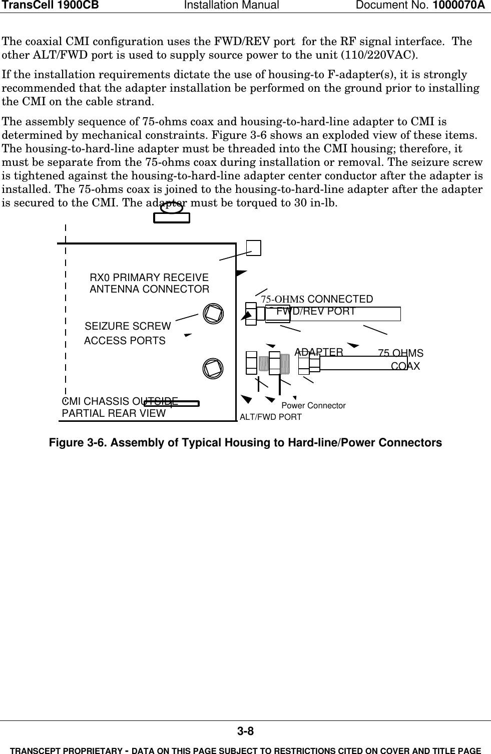
![TransCell 1900CB Installation Manual Document No. 1000070A4-5TRANSCEPT PROPRIETARY - DATA ON THIS PAGE SUBJECT TO RESTRICTIONS CITED ON COVER AND TITLE PAGEBTSγ DIV Rxγ XMIT & PRI RxForwardSplitReverseCombineandSplitHICαβγDuplexerDuplexerDuplexerα XMIT & PRI Rxβ XMIT & PRI Rxβ DIV Rxα DIV Rx(α,β, γ)FIBERNODESFiber OpticNetworkRxdRxpTxCOAXIAL CABLECMIFIBERHUBRxdRxpTxCMI(α,β, γ)RxdRxpTxCMIFigure 4-2. Sector Dedicated to TransCell 1900CB with Unequal Timing Links4.2.2.2 Basic BTS Settings for Dedicated Sector with Unequal TimingFor the dedicated sector with unequal timing, the two basic TIA/EIA-95-B settings alreadydiscussed—time reference and search window size—must be taken into account, andpossibly differential timing as well. The following procedures are recommended fordetermining the setting of the two basic parameters.Time reference is calculated in the same manner as it was in section 4.2.1.2, except that itis established by determining the delay along both links to each CMI and comparing them.The delay calculations are made in each direction utilizing Equation [1]. The time referenceis determined by taking the delay that is the smallest and represents the nearest CMItimewise. The forward path timing delay (Equation [1]) should be added to the defaultsetting for “Tx_offset”. The reverse path time reference should be added to the defaultsetting for “Rx_offset”.The search window size is set in the same manner as it was in section 4.2.1.2. Equation [2]is used to determine the search window size in µs based on the longest delay path and theshortest delay path regardless of which link they are on. The shortest delay path is also atthe CMI whose nearest antenna is 0 system time set point. These two values are calculatedwith Equation [1]. Table 4-1 is then referred to for the setting once the window size isdetermined.](https://usermanual.wiki/OpenCell/0012TC19001/User-Guide-132474-Page-69.png)
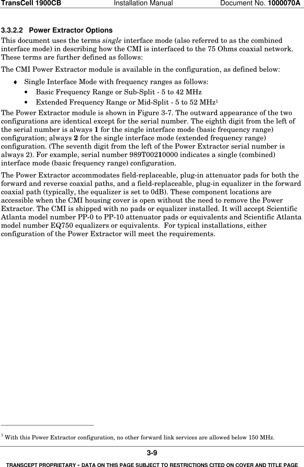
![TransCell 1900CB Installation Manual Document No. 1000070A4-6TRANSCEPT PROPRIETARY - DATA ON THIS PAGE SUBJECT TO RESTRICTIONS CITED ON COVER AND TITLE PAGE4.2.3 Simulcasting with a Tower - Timing Equal Within TransCell 1900CB4.2.3.1 DescriptionThis architecture, shown in Figure 4-3, is similar to that shown in Figure 4-1 except thatthe BTS interface is through a coupled port. The RF for the alpha sector is split betweenTransCell 1900CB and the tower antenna. This is a tower-CMI simulcast and can be doneon all three sectors, although Figure 4-3 shows it only for the alpha sector. The HFCphysical layer for forward and reverse links is either shared or parallel and has the samedelay times from BTS to CMI antenna.Timing between links is equalized on the HFC network and TransCell 1900CB equipmentbut not with the tower antenna. There will be a significant delay to the CMI because of theHFC network and TransCell 1900CB group delay. PCS communications to the wirelesshandset on the alpha sector can be through either the CMIs or the tower, and they canhand off to each other. In handing off from the tower to the CMI, the BTS would regard theCMI signal as a delayed multipath. To discriminate signals from the CMI to the tower, theBTS would regard the tower signal as an advanced multipath.4.2.3.2 Basic BTS Settings for Shared Sector with Equal TimingFor the shared sector, two basic TIA/EIA-95-B settings must be taken into account as inthe previous cases, time reference and search window size. The following procedures arerecommended for determining the setting of the two basic parameters.Time reference is determined at the tower antenna, not the CMI, and assumes that towerantenna distance from the BTS is less than the distance to the first CMI. This avoidsnegative time and meets the TIA/EIA-95-B standard definitions for absolute time. Thedelay is calculated from Equation [1] using only the DCOAX term, which defines the delayover the heliax that runs from the BTS to the tower antenna.ForwardSplitReverseCombineandSplitHICαβγ(α,β, γ)FIBERNODESFiber OpticNetworkRxdRxpTxCOAXIALCABLECMIFIBERHUBRxdRxpTxCOAXIALCABLECMI(α,β, γ)RxdRxpTxCOAXIALCABLECMIDpxBTSγ DIV Rxγ Tx & PRI Rxα Tx & PRI Rxβ Tx & PRI Rxβ DIV Rxα DIV RxRxdTx/RxpRxdTx/RxpβγRxdα30 dBcouplerTx/Rxp30 dBcouplerFigure 4-3. Tower Sector Split with TransCell 1900CB - Timing Equal](https://usermanual.wiki/OpenCell/0012TC19001/User-Guide-132474-Page-70.png)
![TransCell 1900CB Installation Manual Document No. 1000070A4-7TRANSCEPT PROPRIETARY - DATA ON THIS PAGE SUBJECT TO RESTRICTIONS CITED ON COVER AND TITLE PAGEThe search window size is set in the manner similar to that in paragraph 4.2.1.2 exceptthat the window is centered around the absolute time at the tower antenna where the timereference is set. Equation [2] is used to determine the search window size in µs based onthe longest delay path out to the furthest CMI (calculated with Equation [1]) and theshortest delay path at the time reference antenna (0 second delay). Table 4-1 is thenreferred to for the setting once the window size is determined.It should be noted in this situation that the search window will be opened up more than itwould be for the tower alone. Thus in an established network, where the search windowshave been set prior to the addition of TransCell 1900CB, the search window sizing ofadjacent sectors that can hand off to the CMIs must be reset. The neighbor search windowsfor these sectors must be set at the same value as the active search window for the sectorthat contains the CMIs since the same delay rationale applies whether it is a handoffacross sectors or within a sector.4.2.4 Split Sector - Timing Unequal Within TransCell 1900CB4.2.4.1 DescriptionThis architecture, shown in Figure 4-4, is similar to that shown in Figure 4-2 except thatthe BTS interface is through a coupled port. The RF for the sector is split betweenTransCell 1900CB and the tower antenna. This is a tower-CMI simulcast and can be doneon all three sectors, although Figure 4-3 shows it only for the alpha sector. The HFCphysical layer for forward and reverse links is neither shared nor parallel and has differentdelay times from BTS to different CMI antenna. This is not the case with the tower, whichwill have identical timing on the forward and reverse links. Also, as in section 4.2.3, therewill be a significant delay to the CMI as compared to the tower because of the HFCnetwork and TransCell 1900CB group delay. PCS communications to the wireless handseton the alpha sector can be through either the CMIs or the tower and they can handoff toeach other. As in section 4.2.3, handing off in either direction is not a problem with theproper time reference and window settings.](https://usermanual.wiki/OpenCell/0012TC19001/User-Guide-132474-Page-71.png)
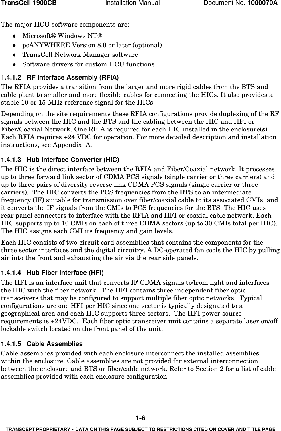
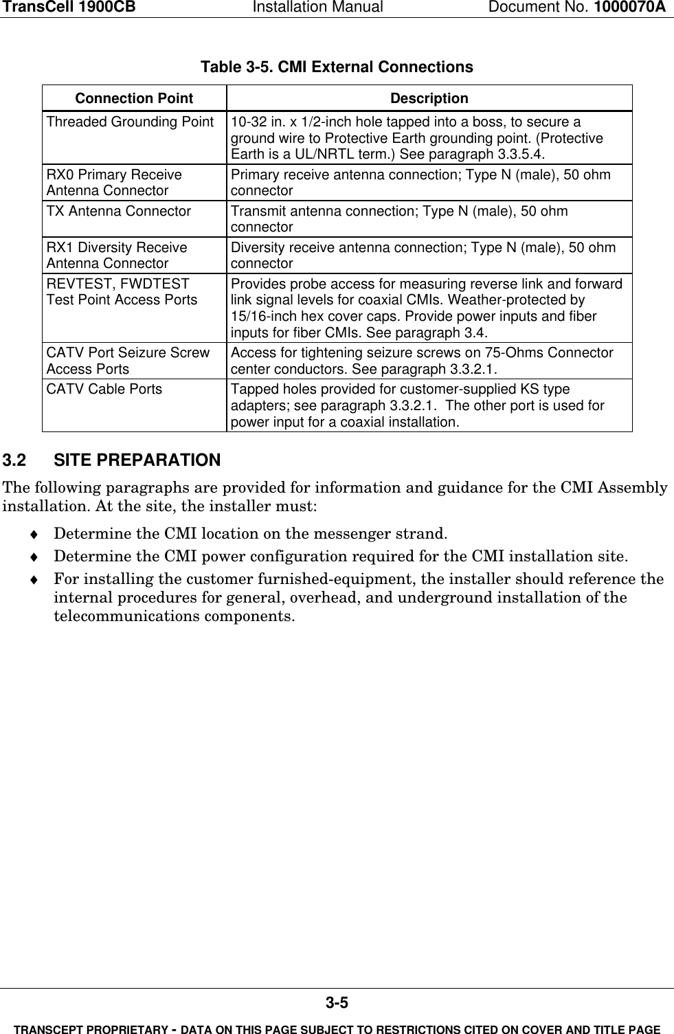
![TransCell 1900CB Installation Manual Document No. 1000070A4-8TRANSCEPT PROPRIETARY - DATA ON THIS PAGE SUBJECT TO RESTRICTIONS CITED ON COVER AND TITLE PAGEForwardSplitReverseCombineandSplitHICαβγDpx(α)FIBERNODESFiber OpticNetworkRxdRxpTxCOAXIAL CABLECMIFIBERHUBRxdRxpTxCMI(α)RxdRxpTxCMIBTSγ DIV Rxγ Tx & PRI Rxα Tx & PRI Rxβ Tx & PRI Rxβ DIV Rxα DIV RxRxdTx/RxpRxdTx/RxpβγRxdα30 dBcouplerTx/Rxp30 dBcouplerFigure 4-4. Tower Sector Split With TransCell 1900CB - Timing Unequal4.2.4.2 Basic BTS Settings for Shared Sector with Unequal TimingFor the shared sector, two basic TIA/EIA-95-B settings must be taken into account as inthe previous cases, time reference and search window size. The following procedures arerecommended for determining the setting of the two basic parameters.As in section 4.2.3, time reference is determined at the tower antenna, not the CMI. Thedelay is calculated from Equation [1] using only the DCOAX term, which defines the delayover the heliax which runs from the base station to the tower antenna.The search window size is set in the manner similar to that in section 4.2.1.2 except thatthe window is centered around the absolute time at the tower antenna where the timereference is set, and calculations must be made for both the forward and reverse link of allCMIs. Equation [2] is used to determine the search window size in µs based on the longestdelay path out to the furthest CMI (calculated with Equation [1]) and the shortest delaypath at the time reference antenna (0 second delay). Table 4-1 is then referred to for thesetting once the window size is determined.As was noted in section 4.2.3.2, the search window will be opened up more than it would befor the tower alone. In an established network, the search window sizing of adjacentsectors that can hand off to the CMIs must be reset. The neighbor search windows for thesesectors must be set at the same value as the active search window for the sector thatcontains the CMIs since the same delay rationale applies whether it is a handoff acrosssectors or within a sector.](https://usermanual.wiki/OpenCell/0012TC19001/User-Guide-132474-Page-72.png)