OpenCell 0012TC19001 PCS-over-Cable Base Station User Manual 1000070A
OpenCell Corp PCS-over-Cable Base Station 1000070A
OpenCell >
Exhibit D Users Manual 2 1033 c 3

TRANSCEPT PROPRIETARY
TRANSCEPT PROPRIETARY
TransCell 1900CB System
Installation Manual for Use with
Fiber and Coaxial Cable Networks
Document No. 1000070
Revision A
November 14, 2000
THIS DOCUMENT CONTAINS PROPRIETARY INFORMATION OF TRANSCEPT, INC, AND IS NOT TO BE
USED FOR ANY PURPOSE, EXCEPT IN ACCORDANCE WITH CONTRACTUAL NONDISCLOSURE
TERMS. THIS DOCUMENT IS NOT TO BE DUPLICATED IN WHOLE OR IN PART WITHOUT PRIOR
WRITTEN PERMISSION FROM A DULY AUTHORIZED REPRESENTATIVE OF TRANSCEPT, INC.
THE REVISION STATUS OF ALL PAGES IN THIS DOCUMENT IS THE SAME AS THAT STATED ON THIS
COVER.
Copyright 1999, 2000 Transcept, Inc
All rights reserved.

TRANSCEPT PROPRIETARY
TRANSCEPT PROPRIETARY
TransCell 1900CB System
Installation Manual for Use with
Fiber and Coaxial Cable Networks
REVIEW AND CONCURRENCE
STEVE DALE, APPLICATION ENGINEERING DATE
MATTHEW HUBBARD, APPLICATION ENGINEERING
CHRISTOPHER COLE, DIRECTOR, PRODUCT
MANAGEMENT
DATE
ERIK DEVINNEY, CONTINUATION ENGINEERING
MANAGER
DATE
THIS DOCUMENT CONTAINS PROPRIETARY INFORMATION OF TRANSCEPT, INC, AND IS NOT TO BE
USED FOR ANY PURPOSE, EXCEPT IN ACCORDANCE WITH CONTRACTUAL NONDISCLOSURE
TERMS. THIS DOCUMENT IS NOT TO BE DUPLICATED IN WHOLE OR IN PART WITHOUT PRIOR
WRITTEN PERMISSION FROM A DULY AUTHORIZED REPRESENTATIVE OF TRANSCEPT, INC.
Document No. 1000070
Revision A:

TRANSCEPT PROPRIETARY
TRANSCEPT PROPRIETARY
DRAWING NO. 1000070
DOCUMENT CHANGE HISTORY
DATE REV DESCRIPTION APPD
11/14/00 AReleased to ECO control per RN001114 km/ED

TransCell 1900CB Installation Manual Document No. 1000070A
i
TRANSCEPT PROPRIETARY - DATA ON THIS PAGE SUBJECT TO RESTRICTIONS CITED ON COVER AND TITLE PAGE
TABLE OF CONTENTS
Paragraph Page
1INTRODUCTION...............................................................................................................1-1
1.1 SCOPE ...........................................................................................................................1-1
1.2 TERMINOLOGY, ACRONYMS, AND ABBREVIATIONS.............................................................1-2
1.2.1 TransCell 1900CB Terminology .............................................................................1-2
1.2.2 Acronyms and Abbreviations..................................................................................1-2
1.2.3 Notation Conventions in this Manual......................................................................1-3
1.3 REFERENCE DOCUMENTATION.........................................................................................1-3
1.4 SYSTEM OVERVIEW ........................................................................................................1-4
1.4.1 Hub Equipment (HE) Enclosure Configurations .....................................................1-5
1.4.1.1 Hub Control Unit (HCU) ..................................................................................1-5
1.4.1.2 RF Interface Assembly (RFIA) ........................................................................1-6
1.4.1.3 Hub Interface Converter (HIC) ........................................................................1-6
1.4.1.4 Hub Fiber Interface (HFI)................................................................................1-6
1.4.1.5 Cable Assemblies ...........................................................................................1-6
1.4.1.6 Equipment enclosure ......................................................................................1-7
1.4.1.7 +24 VDC Power Supply Assembly (Optional)..................................................1-7
1.4.2 Remote Fiber Interface (RFI) .................................................................................1-7
1.4.3 Cable Microcell Integrator (CMI) ............................................................................1-7
1.4.3.1 Power Extractor ..............................................................................................1-8
1.4.3.2 Internal Fiber Transceiver ...............................................................................1-8
1.4.3.3 Transceiver.....................................................................................................1-9
1.4.3.4 Power Supply................................................................................................1-10
1.4.3.5 Power Amplifier.............................................................................................1-10
1.4.4 CMI Antennas ......................................................................................................1-10
1.4.5 Outdoor Enclosure Unit).......................................................................................1-10
2HUB PRIMARY/EXPANSION RACK INSTALLATION......................................................2-1
2.1 INSTALLATION TASKS ......................................................................................................2-1
2.2 TOOLS, TEST EQUIPMENT, AND SUPPLIES........................................................................2-1
2.3 INSTALLATION PARTS LIST...............................................................................................2-2
2.4 POWER REQUIREMENTS..................................................................................................2-3
2.4.1 Typical Prime Power Requirements .......................................................................2-3
2.4.2 Protective Earth Grounding....................................................................................2-3
2.5 HUB EQUIPMENT CONFIGURATION AND SPACE REQUIREMENTS..........................................2-3
2.5.1 Suggested Floor Space Requirements...................................................................2-3
2.5.2 Floor Loading Requirements..................................................................................2-3
2.5.3 Typical Enclosure Configuration.............................................................................2-3
2.6 INSTALLATION OF ASSEMBLIES IN EQUIPMENT ENCLOSURE............................................2-5
2.6.1 Hub Enclosure Installation......................................................................................2-5
2.6.1.1 Hub +24 VDC Power Supply Installation.........................................................2-5
2.6.1.2 Hub Control Unit (HCU) Installation ................................................................2-6
2.6.1.3 +24 VDC Prime Power Installation..................................................................2-8
2.6.1.4 Initial Prime Power Test ..................................................................................2-8
2.6.1.5 Initial HCU Test...............................................................................................2-8
2.6.1.6 RF Interface Assembly (RFIA) Installation ......................................................2-9
2.6.1.7 Hub Fiber Interface (HFI) (Option) ..................................................................2-9
2.6.1.8 Hub Interface Converter (HIC) Installation ....................................................2-10
2.6.1.9 Digital Communications Wiring Installation ...................................................2-11

TransCell 1900CB Installation Manual Document No. 1000070A
ii
TRANSCEPT PROPRIETARY - DATA ON THIS PAGE SUBJECT TO RESTRICTIONS CITED ON COVER AND TITLE PAGE
2.7 HUB EQUIPMENT CABLE INSTALLATION...........................................................................2-11
2.7.1 10/15 MHz Reference cable Installation between RFIA and HIC..........................2-12
2.7.2 Remote User Interface.........................................................................................2-13
2.7.3 HCU Modem ........................................................................................................2-13
2.8 INSTALLATION CHECKOUT - INITIAL TURN-ON..................................................................2-14
2.8.1 Reverse Link Input from Network Infrastructure...................................................2-14
2.8.2 HIC Initial Turn-on and Communication Test........................................................2-15
2.8.3 HCU Setup for HIC Checkout...............................................................................2-15
2.8.4 HIC Activation ......................................................................................................2-17
2.8.5 HIC Reference and Control Tone Output .............................................................2-19
3CMI INSTALLATION.........................................................................................................3-1
3.1 CMI INSTALLATION REQUIREMENTS .................................................................................3-1
3.1.1 Tools, Test Equipment and Supplies......................................................................3-1
3.1.2 CMI Configurations ................................................................................................3-2
3.1.3 Transcept-Furnished Items for CMI Installation......................................................3-2
3.1.4 Customer-Furnished Items for CMI Installation ......................................................3-2
3.1.5 CMI External Connector Identification....................................................................3-4
3.2 SITE PREPARATION.........................................................................................................3-5
3.3 CMI HARDWARE INSTALLATION GUIDE.............................................................................3-6
3.3.1 CMI Access............................................................................................................3-6
3.3.1.1 Opening the Assembly....................................................................................3-6
3.3.1.2 Closing the Assembly......................................................................................3-6
3.3.2 CMI Port and Power Extractor Configuration Options ............................................3-7
3.3.2.1 CMI CATV Port Configurations .......................................................................3-7
3.3.2.2 Power Extractor Options .................................................................................3-9
3.3.3 Coaxial or Fiber Network Interface to the CMI .....................................................3-11
3.3.4 Power Extractor Reverse Link/Forward Link RF Attenuation (Coaxial Installation)3-11
3.3.5 Installing the CMI .................................................................................................3-11
3.3.5.1 Attaching CMI to Messenger Strand .............................................................3-11
3.3.5.2 Attaching Antennas to Messenger Strand.....................................................3-13
3.3.5.3 Installing and Routing Cables .......................................................................3-14
3.3.5.4 Protective Earth Grounding...........................................................................3-14
3.3.5.5 Antenna Cables ............................................................................................3-15
3.3.6 Power and CDMA SIGNAL Cables ......................................................................3-16
3.3.7 CMI Power Check................................................................................................3-16
3.4 MEASUREMENT TEST POINTS ........................................................................................3-16
3.5 FORWARD LINK CMI INSTALLATION MEASUREMENTS AND ADJUSTMENTS .............................3-17
3.5.1 CMI Forward Link Reference and Control Tone Input Level Check......................3-18
3.6 REVERSE LINK CMI INSTALLATION MEASUREMENTS AND ADJUSTMENTS ..........................3-19
3.6.1 Activate CMI.........................................................................................................3-19
3.6.2 Reverse Link Gain Adjustment.............................................................................3-22
3.6.2.1 Setting CMI Reverse Link Signal Level Setpoint at HIC ................................3-22
3.6.2.2 Measure CMI Reverse Link Control Tone at HIC ..........................................3-23
3.6.3 Adjusting Reverse Gain at the HIC ......................................................................3-24
4BTS INTERFACE AND NETWORK OPTIMIZATION........................................................4-1
4.1 INTRODUCTION ...............................................................................................................4-1
4.2 MEASUREMENT/CALCULATION OF CMI DELAYS ................................................................4-1
4.2.1 Sector Dedicated to TransCell 1900CB - Timing Equal..........................................4-1
4.2.1.1 Description......................................................................................................4-1

TransCell 1900CB Installation Manual Document No. 1000070A
iii
TRANSCEPT PROPRIETARY - DATA ON THIS PAGE SUBJECT TO RESTRICTIONS CITED ON COVER AND TITLE PAGE
4.2.1.2 Basic BTS Settings for Dedicated Sector with Equal Timing...........................4-2
4.2.2 Sector Dedicated to TransCell 1900CB - Timing Unequal......................................4-4
4.2.2.1 Description......................................................................................................4-4
4.2.2.2 Basic BTS Settings for Dedicated Sector with Unequal Timing.......................4-5
4.2.3 Simulcasting with a Tower - Timing Equal Within TransCell 1900CB.....................4-6
4.2.3.1 Description......................................................................................................4-6
4.2.3.2 Basic BTS Settings for Shared Sector with Equal Timing ...............................4-6
4.2.4 Split Sector - Timing Unequal Within TransCell 1900CB........................................4-7
4.2.4.1 Description......................................................................................................4-7
4.2.4.2 Basic BTS Settings for Shared Sector with Unequal Timing ...........................4-8
4.3 ASSESSMENT OF BTS SECTORS......................................................................................4-9
4.4 PHYSICAL INTERFACES WITH BTS...................................................................................4-9
4.4.1 Measurement of HIC Reverse Link Output...........................................................4-12
4.4.1.1 HIC CDMA Reverse Link Output to BTS.......................................................4-13
4.4.2 CDMA Forward Link Input from BTS....................................................................4-14
4.4.3 CDMA Forward Link Output to Coaxial Network ..................................................4-15
4.4.3.1 HIC Forward Link CDMA Pilot Level .............................................................4-16
4.5 INITIAL SETTING OF BTS PARAMETERS ..........................................................................4-19
4.5.1 Initial Conditions...................................................................................................4-19
4.5.2 Guidelines for Initial Setting of Parameters ..........................................................4-19
4.6 OPTIMIZING BTS PARAMETER SETTINGS .........................................................................4-20
APPENDIX A RADIO FREQUENCY INTERFACE ASSEMBLY (RFIA) CONFIGURATION
PROCEDURE......................................................................................................................... A-1
RADIO FREQUENCY INTERFACE ASSEMBLY (RFIA) CONFIGURATION PROCEDURE.. A-2
APPENDIX B PCS CHANNEL NUMBER-TO-FREQUENCY CROSS-REFERENCE ........... B-1
APPENDIX C HIC CHANNEL NUMBER-TO-FREQUENCY CROSS-REFERENCE ............ C-1
ENCLOSURE/HIC DATA SHEET........................................................................................... C-1
CMI DATA SHEET ..................................................................................................................4-1

TransCell 1900CB Installation Manual Document No. 1000070A
iv
TRANSCEPT PROPRIETARY - DATA ON THIS PAGE SUBJECT TO RESTRICTIONS CITED ON COVER AND TITLE PAGE
LIST OF ILLUSTRATIONS
Figure Page
FIGURE 1-1. TRANSCELL 1900CB SYSTEM FUNCTIONAL BLOCK DIAGRAM ...................................1-4
FIGURE 2-1. RECOMMENDED HUB EQUIPMENT FLOOR SPACE......................................................2-4
FIGURE 2-2. TYPICAL ENCLOSURE CONFIGURATION ....................................................................2-4
FIGURE 2-3. +24 VDC POWER SUPPLY REAR PANEL..................................................................2-5
FIGURE 2-4. TYPICAL INDOOR ENCLOSURE CONFIGURATION........................................................2-7
FIGURE 2-5. HCU COMPUTER REAR VIEW .................................................................................2-7
FIGURE 2-6. HIC REAR PANEL.................................................................................................2-10
FIGURE 2-7. HIC POWER WIRING HARNESS 1000062G1..........................................................2-10
FIGURE 2-8. THREE HIC CONTROL INTERCONNECT DIAGRAM (NOT TO SCALE)............................2-11
FIGURE 2-9. HIC COMMUNICATION WIRING HARNESS P/N 8339969G1.....................................2-11
FIGURE 2-10. BTS/HIC/COAXIAL NETWORK RF CABLING DIAGRAM (15MHZ FROM RFIA SHOWN)2-12
FIGURE 2-11. CONFIGURATION OPTIONS DIALOG ..............................................................2-16
FIGURE 2-12. HUB CONTROL PANEL: USER DIALOG...........................................................2-16
FIGURE 2-13. TYPICAL ADD HIC DIALOG.................................................................................2-18
FIGURE 2-14. REFERENCE AND CONTROL TONES DIALOG ...............................................2-20
FIGURE 3-1. CMI CHASSIS RIGHT END VIEW ..............................................................................3-4
FIGURE 3-2. CMI CHASSIS LEFT END VIEW ................................................................................3-4
FIGURE 3-3. CMI BOLT TIGHTENING SEQUENCE .........................................................................3-6
FIGURE 3-4. TYPICAL HOUSING-TO-HARDLINE CONNECTOR INTERFACE .......................................3-7
FIGURE 3-5. PROCEDURE FOR CUTTING CATV PORT CENTER CONDUCTOR TO LENGTH ...............3-7
FIGURE 3-6. ASSEMBLY OF TYPICAL HOUSING TO HARD-LINE/POWER CONNECTORS ....................3-8
FIGURE 3-7. POWER EXTRACTOR.............................................................................................3-10
FIGURE 3-8. POWER SUPPLY INPUT CONNECTOR......................................................................3-10
FIGURE 3-9. CMI BRACKET INSTALLATION ................................................................................3-12
FIGURE 3-10. ANTENNA INSTALLATION (OPTION 1)....................................................................3-13
FIGURE 3-11. ANTENNA INSTALLATION (OPTION 2)....................................................................3-14
FIGURE 3-12. CMI ASSEMBLY REAR VIEW................................................................................3-15
FIGURE 3-13. CMI TEST POINT ACCESS AND SUBASSEMBLY LAYOUT.........................................3-17
FIGURE 3-14. TYPICAL HUB CONTROL PANEL DIALOG .........................................................3-19
FIGURE 3-15. TYPICAL HIC CONTROL PANEL DIALOG...........................................................3-21
FIGURE 3-16. TYPICAL ADD CMI DIALOG.................................................................................3-22
FIGURE 3-17. TYPICAL CMI CONTROL PANEL DIALOG ..........................................................3-25
FIGURE 4-1. SECTOR DEDICATED TO TRANSCELL 1900CB WITH EQUAL TIMING LINKS .................4-2
FIGURE 4-2. SECTOR DEDICATED TO TRANSCELL 1900CB WITH UNEQUAL TIMING LINKS .............4-5
FIGURE 4-3. TOWER SECTOR SPLIT WITH TRANSCELL 1900CB - TIMING EQUAL ..........................4-6
FIGURE 4-4. TOWER SECTOR SPLIT WITH TRANSCELL 1900CB - TIMING UNEQUAL .....................4-8
FIGURE 4-5. TYPICAL FORWARD LINK LEVELS; SINGLE CARRIER ...............................................4-10
FIGURE 4-6. TYPICAL FORWARD LINK LEVELS; THREE CARRIER ................................................4-10
FIGURE 4-7. TYPICAL REVERSE LINK LEVELS; SINGLE CARRIER.................................................4-11
FIGURE 4-8. TYPICAL REVERSE LINK LEVELS; THREE CARRIER .................................................4-11
FIGURE 4-9. HIC CONTROL PANEL: DIALOG.........................................................................4-12
FIGURE 4-10. HIC REAR PANEL...............................................................................................4-13
FIGURE 4-11. RFIA REAR PANEL.............................................................................................4-14
FIGURE 4-12. HIC FORWARD POWER DIALOG.....................................................................4-17
FIGURE C-1. RF INTERFACE PLATE ASSEMBLY .......................................................................... C-3
LIST OF TABLES

TransCell 1900CB Installation Manual Document No. 1000070A
v
TRANSCEPT PROPRIETARY - DATA ON THIS PAGE SUBJECT TO RESTRICTIONS CITED ON COVER AND TITLE PAGE
Table Page
TABLE 2-1. ENCLOSURE INSTALLATION TOOLS AND TEST EQUIPMENT ..........................................2-1
TABLE 2-2. HUB EQUIPMENT ENCLOSURE ASSEMBLY INSTALLATION KIT.......................................2-2
TABLE 3-1. CMI INSTALLATION SUPPORT NEEDS ........................................................................3-1
TABLE 3-2. CMI CONFIGURATIONS.............................................................................................3-2
TABLE 3-3. OPTIONAL TRANSCEPT-FURNISHED ITEMS FOR CMI INSTALLATION .............................3-2
TABLE 3-4. CUSTOMER-FURNISHED ITEMS FOR CMI INSTALLATION..............................................3-3
TABLE 3-5. CMI EXTERNAL CONNECTIONS .................................................................................3-5
TABLE 4-1. SEARCH WINDOW SIZES ..........................................................................................4-4
TABLE 4-2. RECOGNIZED ALARM LIST.......................................................................................4-18
TransCell 1900CB Installation Manual Document No. 1000070A
vi
TRANSCEPT PROPRIETARY - DATA ON THIS PAGE SUBJECT TO RESTRICTIONS CITED ON COVER AND TITLE PAGE
♦ High leakage current: The Hub rack, internal or external (environmental) enclosure
must be connected to Protective Earth ground before any connection is made to +24
VDC prime power.
♦ High Voltages (110/220 VAC and 24 VDC) are present within the Hub rack or
environmental enclosure. Use extreme caution when working inside the
rack/enclosure.
♦ High voltages may exist close to the CMI location; use standard electrical industry
safety practices when working on an installed CMI.
♦ High voltages (110/220 VAC RMS) exist on the AC power input to the CMI. Use
extreme caution when removing the AC power cable to avoid coming in contact with
the center conductor.
♦ Laboratory tests conducted in accordance with ANSI/IEEE C95.1-1992 show that a
transmitting CMI poses no radiation hazard to persons in close proximity to the
transmitting antenna. However, for added safety when working near a CMI,
maintain a minimum distance of 12 inches from the transmitting antenna.
ESD CAUTION
The CMI contains circuit card assemblies that are sensitive to
Electrostatic Discharge (ESD) damage. Whenever handling the CMI, use
ESD precautionary procedures to minimize the risk of permanent ESD
damage to circuit card components. Low relative humidity level increases
the potential for damage to ESD-sensitive devices.
FCC License Data
The CMI is licensed by the Federal Communications Commission for operation in the
frequency band as noted on the product label affixed to the CMI Chassis.
National Recognized Test Laboratories (NRTL) Data
Cable Microcell Integrator (CMI), Models 1000000G1-33, 1000501G1-6, 1000601G1-33, and
1000701G1-6: Listed as Communications Service Equipment NRTL 1950
Hub Equipment Racks (Models 1000023P1 and 1000025P1) with the Hub Interface
Converters (Models 1000604G1-3 and 8334760G1-3) and Hub Control Unit Model
(1000015P1): Basic Listing as Information Technology Equipment, Complementary
Listing as Professional Video Equipment

TransCell 1900CB Installation Manual Document No. 1000070A
1-1
TRANSCEPT PROPRIETARY - DATA ON THIS PAGE SUBJECT TO RESTRICTIONS CITED ON COVER AND TITLE PAGE
SECTION 1
INTRODUCTION
1 INTRODUCTION
1.1 SCOPE
This manual contains installation and checkout instructions for the components of the
TransCell 1900CB system. The TransCell 1900CB system provides the means to distribute
wireless Personal Communications Services (PCS) telephony signals encoded with the
Code Division Multiple Access (CDMA) protocol over fiber or coaxial cable infrastructures.
This manual addresses the TransCell 1900CB installation for both fiber and coaxial
networks, and for both indoor and outdoor Hub equipment, distinguishing the unique
requirements for each case as needed. The manual is organized as follows:
♦ Section 1, Introduction - terminology definitions, brief descriptions of the TransCell
1900CB system and its major components
♦ Section 2, Hub Indoor/ Outdoor Rack Installation - installation and checkout of the
Hub Equipment (HE) rack configurations; installation of the Hub Control Unit
(HCU), and the Hub Interface Converter (HIC)
♦ Section 3, CMI Installation - Cable Microcell Integrator (CMI) installation and
checkout of the outside cable network at selected remote locations in the service
area
♦ Section 4, BTS Interface and Network Optimization - measurement and adjustment
procedures for optimal integration of the TransCell 1900CB system with the Base
Transceiver Stations (BTS), with variations according to BTS manufacturer
♦ Appendix A, Radio Frequency Interface Unit (RFIA) Installation - installation of the
RFIA, to provide a cable transition at the HIC, provide a stable 10 or 15 MHz
reference signal for the HICs in the primary or expansion racks and the duplexing
of signals between the HICs and the BTS
♦ Appendix B, PCS channel-number-to-frequency cross-reference table
♦ Appendix C, HIC Channel Number-to-frequency cross-reference table

TransCell 1900CB Installation Manual Document No. 1000070A
1-2
TRANSCEPT PROPRIETARY - DATA ON THIS PAGE SUBJECT TO RESTRICTIONS CITED ON COVER AND TITLE PAGE
1.2 TERMINOLOGY, ACRONYMS, AND ABBREVIATIONS
1.2.1 TransCell 1900CB Terminology
The following words and phrases are used throughout this manual when referring to signal
flow over the fiber/cable network, between the subscriber’s PCS handset and the wireless
telephony network’s BTS:
♦ Forward Link – direction of the fiber/cable network from the HIC to the CMI,
supporting communications from the BTS to subscriber units.
♦ Forward Path - the physical/electrical path for forward link signals
♦ Reverse Link – direction of the fiber/cable network from the CMI to the HIC,
supporting communications from subscriber units to the BTS.
♦ Reverse Path - the physical/electrical path for reverse link signals
1.2.2 Acronyms and Abbreviations
AWG American Wire Gage NOCC Network Operation Control Center
BTS Base Transceiver Station NRTL National Recognized Test Lab
CDMA Code Division Multiple Access OA&M Operation, Administration, and
Maintenance
CMI Cable Microcell Integrator PCS Personal Communications Services
CRT Cathode Ray Tube PEGND Protective Earth Ground
Ctl Control PN Pseudo Noise
EIA Electronic Industries Association POTS Plain Old Telephone Service
ESD Electrostatic Discharge RBW Resolution Bandwidth
FCC Federal Communications Commission RCV Receive
FWD Forward (BTS to Subscriber) Ref Reference
HCU Hub Control Unit REV Reverse (Subscriber to BTS)
HE Hub Equipment RFIA Radio Frequency Interface Assembly
HFC Hybrid Fiber Coax Infrastructure RTN Return
HIC Hub Interface Converter Rx Receive
IF Intermediate Frequency SMIU Sector Management Interface Unit
kbps Kilobits Per Second Tx Transmit
LED Light Emitting Diode UL Underwriters Laboratories
MHz Megahertz XMIT Transmit

TransCell 1900CB Installation Manual Document No. 1000070A
1-3
TRANSCEPT PROPRIETARY - DATA ON THIS PAGE SUBJECT TO RESTRICTIONS CITED ON COVER AND TITLE PAGE
1.2.3 Notation Conventions in this Manual
This manual assumes that the user has a basic knowledge of the Windows NToperating
system. Several typographic conventions and standard Windows NT terms are used in
this manual when discussing the TransCell Network Manager software. They are as
follows:
Mouse Commands - The TransCell Network Manager software uses only the left mouse
button:
♦ “click” - press and release the left mouse button
♦ “double-click” - press and release left mouse button twice in quick succession
Menu Commands - Menu commands are bolded with each command level separated from
the previous one by a slash (/) mark, e.g., “Select Privileges/Modify Privileges.”
Button Names – Command button names in dialogs are underlined, e.g., “To confirm
selection, click OK.”
Key Names - Key names are spelled out and appear in small, bold capital letters, e.g.
ENTER, ESCAPE, AND CONTROL.
Dialogs and Messages - Dialog and message titles appear in all upper case (capital) letters,
and generally the name is referenced exactly as shown on the title bar, e.g., the PCS
FREQUENCY dialog. However, in cases where the dialog title varies according to privilege
level, enclosure, or sector, the title is shortened to exclude this variable information unless
the variable is important. If a dialog title is referenced that includes a specific HIC or CMI
number, the number is represented by the bracketed letter n: e.g., CMI CONTROL
PANEL: ALPHA SECTOR, CMI [n].
Dialog Options - Dialog options (text boxes and radio buttons) are shown in italics, e.g.,
“Type in the desired PCS Frequency.” All instructions to “select” or “choose” an option
imply clicking on that option, although options can be selected via the keyboard as well.
Keyboard Input - Instructions for keyboard entries start with “Type in...”, and anything
that should be typed in verbatim is shown in a contrasting font. For example, “Type in
config01.dtb in the File Name box.”
Displayed Text - Text displayed in a dialog box is shown in another contrasting font, e.g.,
“The CONFIGURATION OPTIONS dialog displays the query “Do you Want To Restore
a Pre-existing Configuration?”.
1.3 REFERENCE DOCUMENTATION
♦ Hub Control Unit (HCU)-associated vendor hardware/software documentation
(Computer, Monitor, Watchdog Timer, etc.) Transcept Document No. 1000015P1
♦ TransCell 1900CB System Acceptance Test Procedure Requirements, Transcept
Document No. 1000095
♦ Mobile Station-Base Station Compatibility Std for Wideband Spread Spectrum
Cellular Systems, TIA/EIA-95-B
TransCell 1900CB Installation Manual Document No. 1000070A
1-4
TRANSCEPT PROPRIETARY - DATA ON THIS PAGE SUBJECT TO RESTRICTIONS CITED ON COVER AND TITLE PAGE
1.4 SYSTEM OVERVIEW
The TransCell 1900CB system permits the transport of CDMA PCS signals between a Base
Transceiver Station (BTS) and mobile users over fiber/coaxial cable infrastructures. The
cable network (fiber, coax, or hybrid) is used to distribute the PCS signals between the
cable Hub or hub facility and attached remote locations throughout the service area.
The TransCell 1900CB system has four primary components: Cable Microcell Integrator
(CMI), Hub Interface Converter (HIC), RF Interface Assembly (RFIA), and Hub Control
Unit (HCU) and two fiber optic peripherals: Hub Fiber Interface (HFI) and Remote Fiber
Interface (RFI). The HICs and CMIs provide the carrier frequency translation and signal
conditioning needed for the CDMA signal (single carrier or three-carrier) interfaces
between mobile user, BTS, and fiber/coaxial network. The HCU provides the operation,
administration, and maintenance (OA&M) functions for the system. The RFI and HFI
provide the conversion between light and RF energy.
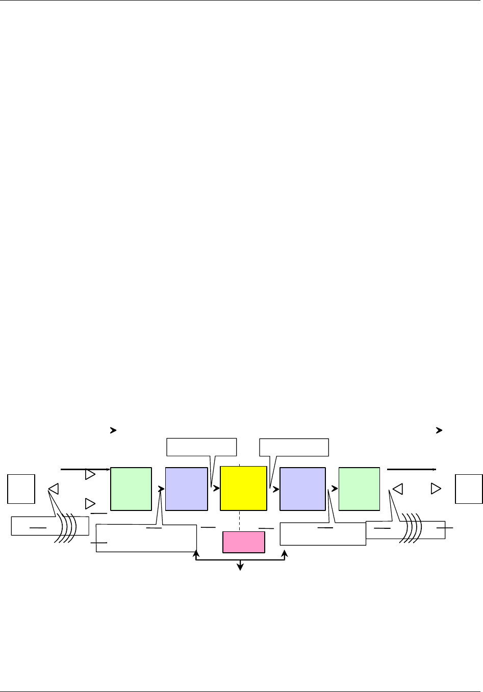
As shown in Figure 1-1, in the reverse path a CMI at a remote location receives a CDMA
signal from a mobile PCS unit via the receive antennas, converts its PCS carrier frequency
to an IF frequency and sends the signal to the associated HIC at the Hub. The HIC
converts the signal carrier back to the PCS frequency and routes the signal to the BTS. The
BTS then switches the signal into the telephone network.
In the forward path, the process is inverted. The HIC receives the CDMA signal from the
BTS, translates the carrier frequency to an IF frequency and sends the signal to the CMI.
The CMI translates the signal carrier back to the PCS frequency, amplifies the signal, and
radiates it via the transmit antenna for capture by the mobile PCS unit. One HIC provides
the BTS interface for up to three CDMA sectors and may control as many as 30 CMIs.
The HICs and CMIs normally handle the transport of PCS traffic over the fiber/coaxial
network without assistance from the HCU. The HCU is used to set up frequency,
attenuation, and fault reporting parameters and to change those parameters as needed. In
normal operation, the HCU allows operators to monitor system operational status and
alarms.
HIC
REVERSE
LINK
HIC
FORWARD
LINK
BASE
TRANSCEIVER
STATION
(BTS)
CMI
PCS
TRANSMIT
FUNCTION
• 1850 to 1910 MHz
• Band Specific Filters
• Fiber/
Coaxial Infrastructure
• Basic - 5 to 52 MHz • 450 to 750 MHz
• 1930 to 1990 MHz
• Band Specific Filters
CMI
PCS
RECEIVE
FUNCTION
MOBILE
PCS
UNIT
• 1850 to 1910 MHz
• CDMA
MOBILE
PCS
UNIT
CONNECTION
TO
TELEPHONE
NETWORK
• 1930 to 1990 MHz
• CDMA
REVERSE FORWARD
HCU
• Fiber/
Coaxial
infrastcr.
Figure 1-1. TransCell 1900CB System Functional Block Diagram

TransCell 1900CB Installation Manual Document No. 1000070A
1-5
TRANSCEPT PROPRIETARY - DATA ON THIS PAGE SUBJECT TO RESTRICTIONS CITED ON COVER AND TITLE PAGE
For installations with existing environmentally controlled indoor Hub or hub facilities, the
typical TransCell 1900CB configuration consists of up to three Hub Equipment (HE)
enclosures stacked, containing a HCU, three Hub Fiber Interface Units (HFIs), three RF
Interface Assemblies (RFIAs), and three HICs. Additional enclosures may be purchased
when more than three HICs are required at a given site. Each HIC is connected to several
CMIs which are installed on the outside fiber/coaxial network.
For ruggedized outdoor installations, the HCU and HICs are housed in an outdoor
environmental controlled enclosure.
Either the indoor or outdoor system installation may also include a network interface unit
to remote the HCU for centralized monitoring and control of PCS network operation.
1.4.1 Hub Equipment (HE) Enclosure Configurations
The HE enclosure contains these major components:
♦ Hub Control Unit (HCU)
♦ RF Interface Assembly (RFIA)
♦ Hub Interface Converters (HICs)
♦ Hub Fiber Interface Unit (HFI) (Optional)
♦ +24 VDC Power Supply (Optional)
There are three stackable enclosure configurations available. One enclosure houses the
HCU (PC, Monitor, and Keyboard). The second enclosure houses an RFIA, HIC, HFI
(optional), Power Supply (Optional), and a network interface box (remote configuration
only). The third enclosure houses two RFIAs, two HICs, and two HFIs (Optional). Section
2 of this manual contains a detailed assembly list for each enclosure configuration. The
following paragraphs describe the major assemblies that are normally installed in the
configurations along with some optional assemblies.
1.4.1.1 Hub Control Unit (HCU)
The HCU is installed in one Hub equipment enclosure. A single HCU supports up to 26
HICs. The HCU may also be installed in a central location (NOCC) and remoted to an
outside enclosure. This configuration is used for those installations in uncontrolled
environments. The major HCU hardware components are:
♦ Computer chassis
♦ Color CRT Monitor
♦ Keyboard/Touchpad/Mouse
The HCU is the monitoring and control device for the attached HIC units and their
assigned CMIs. It monitors various system parameters to verify that these units are
operational and that signal power is being maintained at the proper levels. The HCU
communicates with the HICs over an RS-485 interface via a LonWorks® card located in the
computer, and through the HICs it communicates with the CMIs. The HCU interprets all
faults reported by the HICs and CMIs into alarms, which are logged and displayed. The
computer also contains one or more modems for remote monitoring and control of the HCU
located at a central control point.

TransCell 1900CB Installation Manual Document No. 1000070A
1-6
TRANSCEPT PROPRIETARY - DATA ON THIS PAGE SUBJECT TO RESTRICTIONS CITED ON COVER AND TITLE PAGE
The major HCU software components are:
♦ Microsoft® Windows NT
♦ pcANYWHERE Version 8.0 or later (optional)
♦ TransCell Network Manager software
♦ Software drivers for custom HCU functions
1.4.1.2 RF Interface Assembly (RFIA)
The RFIA provides a transition from the larger and more rigid cables from the BTS and
cable plant to smaller and more flexible cables for connecting the HICs. It also provides a
stable 10 or 15-MHz reference signal for the HICs.
Depending on the site requirements these RFIA configurations provide duplexing of the RF
signals between the HIC and the BTS and the cabling between the HIC and HFI or
Fiber/Coaxial Network. One RFIA is required for each HIC installed in the enclosure(s).
Each RFIA requires +24 VDC for operation. For more detailed description and installation
instructions, see Appendix A.
1.4.1.3 Hub Interface Converter (HIC)
The HIC is the direct interface between the RFIA and Fiber/Coaxial network. It processes
up to three forward link sector of CDMA PCS signals (single carrier or three carriers) and
up to three pairs of diversity reverse link CDMA PCS signals (single carrier or three
carriers). The HIC converts the PCS frequencies from the BTS to an intermediate
frequency (IF) suitable for transmission over fiber/coaxial cable to its associated CMIs, and
it converts the IF signals from the CMIs to PCS frequencies for the BTS. The HIC uses
rear panel connectors to interface with the RFIA and HFI or coaxial cable network. Each
HIC supports up to 10 CMIs on each of three CDMA sectors (up to 30 CMIs total per HIC).
The HIC assigns each CMI its frequency and gain levels.
Each HIC consists of two-circuit card assemblies that contains the components for the
three sector interfaces and the digital circuitry. A DC-operated fan cools the HIC by pulling
air into the front and exhausting the air via the rear side panels.
1.4.1.4 Hub Fiber Interface (HFI)
The HFI is an interface unit that converts IF CDMA signals to/from light and interfaces
the HIC with the fiber network. The HFI contains three independent fiber optic
transceivers that may be configured to support multiple fiber optic networks. Typical
configurations are one HFI per HIC since one sector is typically designated to a
geographical area and each HIC supports three sectors. The HFI power source
requirements is +24VDC. Each fiber optic transceiver unit contains a separate laser on/off
lockable switch located on the front panel of the unit.
1.4.1.5 Cable Assemblies
Cable assemblies provided with each enclosure interconnect the installed assemblies
within the enclosure. Cable assemblies are not provided for external interconnection
between the enclosure and BTS or fiber/cable network. Refer to Section 2 for a list of cable
assemblies provided with each enclosure configuration.

TransCell 1900CB Installation Manual Document No. 1000070A
1-7
TRANSCEPT PROPRIETARY - DATA ON THIS PAGE SUBJECT TO RESTRICTIONS CITED ON COVER AND TITLE PAGE
1.4.1.6 Equipment enclosure
The indoor and outdoor equipment enclosure is a standard EIA design that holds and
secures standard 19-inch-wide enclosure-mounted assemblies. The equipment enclosure
dimensions are:
Indoor Enclosure Outdoor Enclosure
♦ Height 24 inches 39 inches (minus lift brackets)
♦ Depth 25 inches 26 inches
♦ Width 20 inches 24 inches
1.4.1.7 +24 VDC Power Supply Assembly (Optional)
For installation sites where an external +24 VDC prime power source is unavailable, an
optional +24 VDC Power Supply is available for enclosure installation. The +24 VDC Power
Supply operates on either 110 or 220 VAC. The +24 VDC Power Supply will be used to
power all three of the HICs installed in an enclosure.
1.4.2 Remote Fiber Interface (RFI)
The RFI is a fiber node. The unit contains a fiber optic transceiver and an AC
(110/220VAC) to DC power supply. The RFI resides at the demarcation point, between the
Hub HFI and a network of Coaxial CMIs, where the fiber no longer is available and coaxial
cable must be extended to the CMIs.
1.4.3 Cable Microcell Integrator (CMI)
The CMI is the communications link between the PCS handset and the fiber/cable network.
It processes a single forward link and single pair of diversity reverse link CDMA PCS
carriers (single carriers or three-carriers). Each CMI is controlled by its assigned HIC. The
CMI is comprised of the following major hardware assemblies:
♦ Power Extractor - routes the tapped coaxial IF CDMA signals to/from the RF
Transceiver in a coaxial CMI.
♦ Internal Fiber Interface – converts light to/from the IF frequencies to/from the RF
transceiver in a fiber CMI.
♦ Transceiver - responds to control messages from the assigned HIC and converts the
CDMA signals to the appropriate transmission frequencies.
♦ Power Amplifier - enabled/disabled by the assigned HIC; boosts the CDMA signal
sent to the PCS handset via an antenna.
♦ Power Supply - converts the 110/220VAC power to the DC voltages required by the
Transceiver, Internal Fiber Interface, and Power Amplifier.
♦ CMI Housing Assembly - environmentally sealed fireproof enclosure for all of the
four CMI assemblies.
♦ Antennas – one transmit and two receive, typically omnidirectional. Antennas are
optionally available from Transcept, depending on customer preference.

TransCell 1900CB Installation Manual Document No. 1000070A
1-8
TRANSCEPT PROPRIETARY - DATA ON THIS PAGE SUBJECT TO RESTRICTIONS CITED ON COVER AND TITLE PAGE
1.4.3.1 Power Extractor
The CMI Power Extractor is available in two configurations:
♦ Single (or Combined) Mode, Sub-Split: Basic frequency range - 5 to 42 MHz
♦ Single (or Combined) Mode, Mid-Split: Extended frequency range - 5 to 52 MHz
The Power Extractor routes the following signals:
♦ Reverse link signals from the Transceiver module, 5 to 42 MHz (basic) or 5 to 52
MHz (extended)
♦ Forward link signals to the Transceiver module, 450 to 750 MHz
NOTE
References to reverse link frequency range in this manual imply a range of 5
to 52 MHz. However, if a single mode sub-split (basic) Power Extractor
module is installed in a CMI, the range for that CMI will be 5 to 42 MHz.
The relationship between the Power Extractor configuration and the way in which the CMI
is electrically connected to the coaxial cable is as follows:
♦ The Single Mode is configured to operate with both the forward and reverse link
signals on a single interface port (FWD/REV). The CMI is configured in this mode
by installing the Single Mode, Sub-Split (basic frequency range) or the Single Mode,
Mid-Split (extended frequency range) Power Extractor module.
The Power Extractor accommodates field-replaceable, plug-in attenuator pads for both the
forward and reverse paths, and a field-replaceable, plug-in equalizer (should be zero for
typical installations) in the forward path. These component locations are accessible when
the CMI housing cover is open, without the need to remove the Power Extractor. The CMI
is shipped with no pads or equalizer installed. It will accept Scientific Atlanta model
numbers PP-0 to PP-10 attenuator pads, or equivalent, and Scientific Atlanta model
number EQ750 equalizers, or equivalent.
1.4.3.2 Internal Fiber Transceiver
The Internal Fiber Transceiver converts 1310nm-laser light to IF energy that feeds the RF
Transceiver in the forward direction. In the reverse direction, the unit converts IF energy
from the RF Transceiver to 1550nm light (2mW max). The power interface to the Internal
Fiber Interface is DC power coming from the power supply. The fiber optic cable is
connected to the fiber network via a coupler and passes through a housing interface and
connected directly to the Internal Fiber Transceiver.

TransCell 1900CB Installation Manual Document No. 1000070A
1-9
TRANSCEPT PROPRIETARY - DATA ON THIS PAGE SUBJECT TO RESTRICTIONS CITED ON COVER AND TITLE PAGE
1.4.3.3 Transceiver
The Transceiver contains a dual receiver and a transmitter, and incorporates both analog
and digital signal processing and control. Reverse link RF signals, originating in the PCS
wireless domain, are received by both the primary and diversity receivers, processed and
sent, via the coaxial/fiber network, to a Hub location. Forward link signals, originating at
the Hub, travel via the coaxial/fiber network to the CMI where they are processed by the
transmitter and sent to the Power Amplifier.
The Transceiver has four LED indicators on its outer surface, clearly visible when the CMI
cover is open. One LED is normally lit to indicate presence of +5 VDC power, while the
other three are normally unlit. These three LEDs light only to indicate particular
Transceiver fault conditions. The Transceiver is available in three different PCS frequency
band sets (A/D, B/E, C/F) (see Table 3-2); the desired band set is selected at the time of
order.

TransCell 1900CB Installation Manual Document No. 1000070A
1-10
TRANSCEPT PROPRIETARY - DATA ON THIS PAGE SUBJECT TO RESTRICTIONS CITED ON COVER AND TITLE PAGE
1.4.3.4 Power Supply
The Power Supply requires a 110/220VAC, 50/60-Hz voltage input. It produces four DC
voltages, +25V, +15V, +5V, and -15V, for use by the Transceiver and Power Amplifier. For
overcurrent protection, the Power Supply AC input is fused. The fuse is accessible with the
power supply cover removed.
1.4.3.5 Power Amplifier
The Power Amplifier operates in one of three 20-MHz pass bands corresponding to the
selected Transceiver frequency band for a single carrier CMI. For a multi-carrier (three)
unit, the power amplifier covers the entire 60MHz pass band. Power Amplifier parameters
include:
• Gain Approximately 60 dB
• Power Output +35.0 dBm/+39.0dBm max
• Power Output Dynamic Range 15 dB minimum
1.4.4 CMI Antennas
The CMI requires three antennas for operation: two receive and one transmit. For typical
aerial operation, 6-dBi gain antennas, approximately 8 inches in length, are used. The
receive antennas are installed on brackets and extend below a messenger strand. The
transmit antenna is installed on a bracket and extends above a messenger strand. A
separation of six feet between the diversity receive antennas is recommended to achieve
reasonable spatial diversity. The use of the 6-dBi gain antennas with a minimum transmit-
to-receive antenna distance of 36 inches will achieve the required transmit-to-receive
antenna isolation in excess of 40 dB. See the paragraph 3.3.5.2 for installation procedures.
1.4.5 Outdoor Enclosure Unit)
The outdoor enclosure configuration is a ruggedized equivalent of an indoor enclosure
without the HCU, used for installation in uncontrolled environments. The enclosure
accommodates a network interface unit, HIC, an RFIA (timing reference source), a
+24VDC power supply (optional), and a heating/cooling unit. All modules in the enclosure
are either rack mountable or mounted on 19-inch trays. The maximum footprint of the
pedestal is 24 x 26 inches. The maximum height of the cabinet is 45 inches (including lift
brackets). The enclosure conforms to NEMA 3R requirements.

TransCell 1900CB Installation Manual Document No. 1000070A
2-1
TRANSCEPT PROPRIETARY - DATA ON THIS PAGE SUBJECT TO RESTRICTIONS CITED ON COVER AND TITLE PAGE
SECTION 2
HUB ENCLOSURE INSTALLATION
2 HUB PRIMARY/EXPANSION RACK INSTALLATION
This section describes the installation of the Hub equipment and their constituent
components. Most of the component installation procedures are identical between the
indoor and outdoor configurations; differences are stated in the installation procedures.
2.1 INSTALLATION TASKS
Installing the Hub equipment involves the following major tasks:
♦ Preparing space for the individual enclosure
♦ Installing equipment in the enclosure
♦ Installing interconnecting cables in the rack
♦ Installing interconnecting cables between equipment and fiber/coaxial network
♦ Installing interconnecting cables between equipment and BTS
♦ Installing interconnecting cables between HIC and HFI
♦ Installation checkout
2.2 TOOLS, TEST EQUIPMENT, AND SUPPLIES
Table 2-1 lists the tools and test equipment needed (but not supplied) to support the
enclosure installation.
Table 2-1. Enclosure Installation Tools and Test Equipment
Hand Tools Test Equipment
• Philips Screwdriver # 2 head • Hand-held Digital Multimeter with test probes
• Flat Blade Screwdriver # 2 head • Spectrum Analyzer, HP 8593 or equivalent
• Wrench, 5/16 inch
• Wrench, 7/16 inch
• Wrench, 3/8 inch
• Nut Driver ¼ inch
• Tape Measure
• Torque Wrenches
• Cable Tie Installation Tool, Panduit GS2B,
or equivalent

TransCell 1900CB Installation Manual Document No. 1000070A
2-2
TRANSCEPT PROPRIETARY - DATA ON THIS PAGE SUBJECT TO RESTRICTIONS CITED ON COVER AND TITLE PAGE
2.3 INSTALLATION PARTS LIST
Table 2-2 lists the typical parts shipped for each Hub installation. Before proceeding with
the installation, inventory the kit contents to ensure all parts are present for the applicable
installation.
Table 2-2. Hub Equipment Enclosure Assembly Installation Kit
Assembly Item Part No.
Indoor Enclosure
1000023P1
Outdoor Enclosure
8339254G1
Equipment enclosure
Indoor Hub Enclosure 1000023P1 Up to 3
Outdoor Hub Enclosure 1000025P1 1
Hub Enclosure Stacking Kit 1000059G1 Up to 2
Hub Enclosure Cable Kit 1000064G1 Up to 3 1
Hub Power Supply Assembly (Optional) 1000056G1 1 (Optional) 1 (Optional)
Communications Harness 1000063G1 1 1
Cable ties, 12 inches long PLT3S-C 12 12
Cable ties, 5.25 x 3.32 inches SST1.5I-C 10 2
Cable Tie Mount, Self Adhesive ABMM-AT-C 2 2
Cable Clamp, 3/8”, Nylon NAS1397P6N 5 2
Busbar Assembly P/O Enclosure Up to 3 1
Equipment
Hub Control Unit (HCU) Assembly
Computer, Pentium
Monitor, 14-inch color
PS/2 Keyboard with Touchpad,
Computer Power Cord
Monitor Power Cord
Rack Mounting Brackets
Windows NT, Version 4.0
PcANYWHERE, Version 8.0 (Optional)
1000022G1 1N/A
Hub Interface Converter (HIC) 1000604G1,G2,
or G3
OR
8334760G1,G2,
or G3
Up to 3
OR
Up to 3
1
Hub Fiber Interface (HFI) (Optional) 1000014P2 Up to 3 (Optional) 1 (Optional)
Hub Power Supply Assembly (Optional) 1000056G1 1 (Optional) 1 (Optional)
RF Interface Assembly (RFIA)1000035G1,G2,
G3 Up to 3 1

TransCell 1900CB Installation Manual Document No. 1000070A
2-3
TRANSCEPT PROPRIETARY - DATA ON THIS PAGE SUBJECT TO RESTRICTIONS CITED ON COVER AND TITLE PAGE
2.4 POWER REQUIREMENTS
Both the indoor and outdoor enclosures require external 110/220 VAC, single phase, 50/60
Hz with use of power supply and HCU, or +24 VDC for prime power.
2.4.1 Typical Prime Power Requirements
When both 110/220 VAC, single phase, 50/60 Hz and +24 VDC are available at the
installation site, an enclosure with 3 HICs/HFIs installed requires approximately 8
amperes of +24 VDC power. The HCU requires approximately 2.0 amperes of 110 VAC,
50/60 Hz (or approximately 1.0 ampere of 220 VAC, 50/60 Hz), single phase power.
2.4.2 Protective Earth Grounding
The Hub Equipment Enclosures must be properly grounded to protect installers and
operators from electrical shock. For this purpose there are two-1/4 in. x 20 ground studs
located on the left and right rear of the enclosure floor panel. These studs are used to
ground the internal components to the enclosure and to connect the enclosure to the site
ground. The site grounding cable should consist of UL-approved wire of no less than 14
gauge. The wire should attach to one of the ground stud by means of a properly sized ring
terminal. The enclosure is supplied with a split washer and a 1/4-in. x 20 nut to secure the
grounding cable ring terminal to the stud.
2.5 HUB EQUIPMENT CONFIGURATION AND SPACE REQUIREMENTS
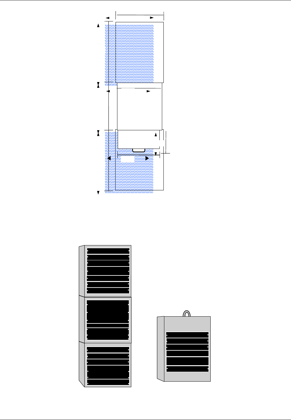
2.5.1 Suggested Floor Space Requirements
Figure 2-1 shows the suggested floor space to support the Indoor Hub Equipment enclosure
installation, operator workspace, and service area.
2.5.2 Floor Loading Requirements
In order to safely support the weight of a fully loaded enclosure unit, the floor of the
installation site must be rated for a load of 150 pounds per square foot or more .
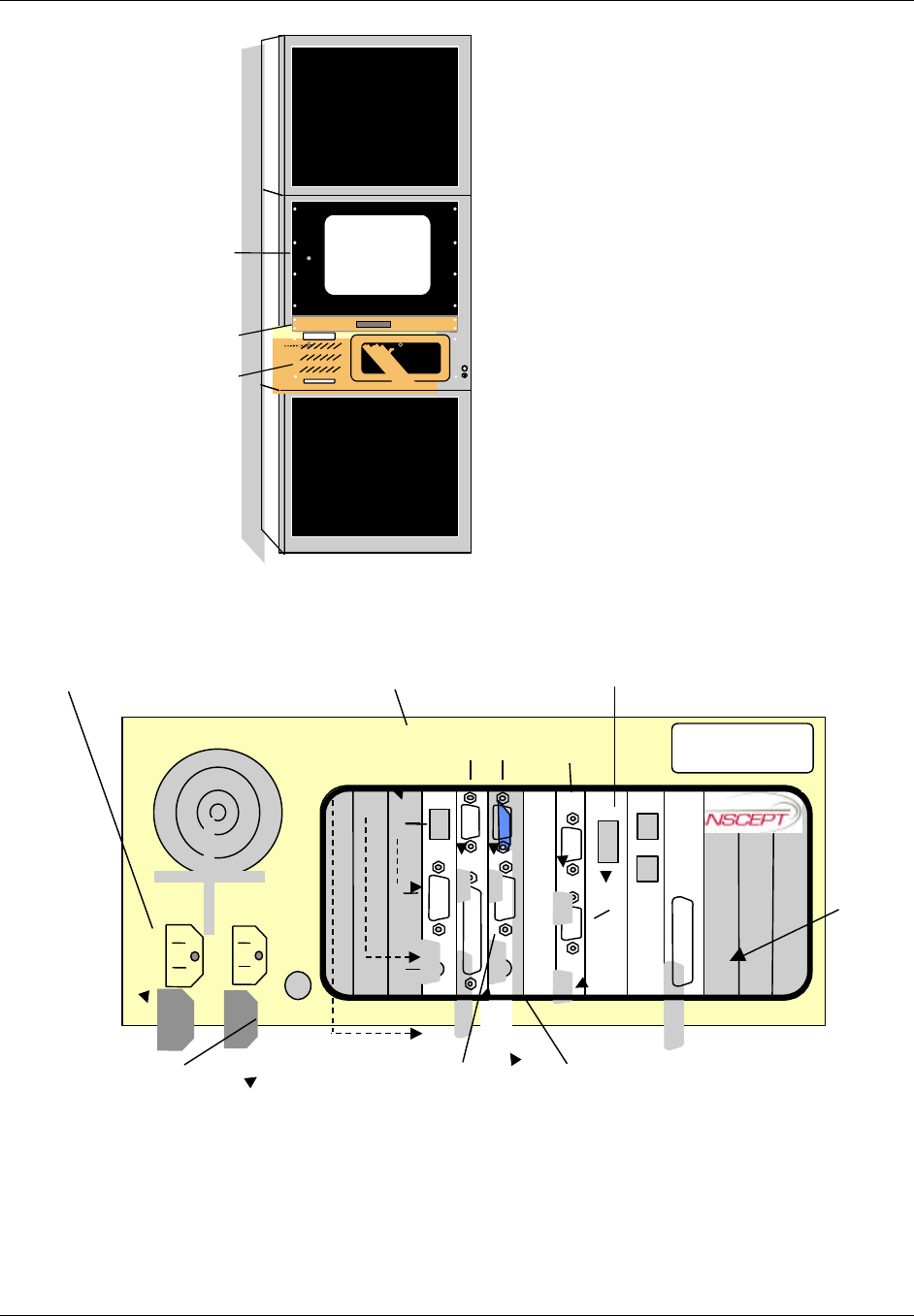
2.5.3 Typical Enclosure Configuration
Figure 2-2 shows a typical enclosure configuration as it appears before installation of the
rack-mounted assemblies. The indoor enclosure configurations use the same enclosures
and are stackable up to three high. Each individual enclosure is 24 inches high, 25 inches
deep, and 20 inches wide (outside dimensions). A minimum of 36 inches of clear space
behind the enclosure is recommended for servicing and proper ventilation. The HCU
contains an extendable keyboard tray, which adds another 36 inches of clearance
requirement in front of the enclosure for operator workspace. The enclosures are bolted
together via the “Hub Enclosure Stacking Kit; PN 1000059G1” and it is recommended that
the enclosure be bolted to the floor.
TransCell 1900CB Installation Manual Document No. 1000070A
2-4
TRANSCEPT PROPRIETARY - DATA ON THIS PAGE SUBJECT TO RESTRICTIONS CITED ON COVER AND TITLE PAGE
SUGGESTED
SERVICE AREA
2
SUGGESTED
SERVICE AREA
1
PULL-OUT KEYBOARD
TRAY WITH TOUCHPAD
NOTES
1. Suggested work area for installation
and maintenance
2. Suggested work area to support
installation and operation
36 IN.
26 IN.
36 IN.
24 IN.
Hub Enclosure
12 IN.
20 IN.
17 IN.
Figure 2-1. Recommended Hub Equipment Floor Space
Indoor Unit
Monitor
Computer
Keyboard
HIC
RFIA
Power Supply (Optional)
HFI
Blank
HIC
RFIA
HFI
HIC
RFIA
HFI
Blank
HIC
RFIA
Power Supply (Optional)
HFI
Network I/F Unit
Blank
Outdoor Unit
Figure 2-2. Typical Enclosure Configuration
TransCell 1900CB Installation Manual Document No. 1000070A
2-5
TRANSCEPT PROPRIETARY - DATA ON THIS PAGE SUBJECT TO RESTRICTIONS CITED ON COVER AND TITLE PAGE
2.6 INSTALLATION OF ASSEMBLIES IN EQUIPMENT ENCLOSURE
Paragraph 2.6.1, Indoor and outdoor enclosure installation, provides step-by-step
instructions for installing hardware assemblies, cables, wiring, etc.
2.6.1 Hub Enclosure Installation
For installation sites that do not provide an external +24 VDC power source, an optional
internal +24 VDC Power Supply, part number 1000056G1, must be installed in the
enclosure. If an external +24 VDC power source is available, skip to paragraph 2.6.1.2.
2.6.1.1 Hub +24 VDC Power Supply Installation
If the +24 VDC Power Supply has been procured as an option, install as follows:
a. Connect Power Supply Input Cable (supplied with unit) to an AC outlet/source as
follows:
Black wire to Line AC (L1) terminal
White wire to Neutral AC (L2) terminal
Green wire to ground terminal
b. Verify polarity of wires, then connect ring terminal ends of Power Supply Output
Cable P/N 1000056G1 to V1 (+) and (–) terminals.
NOTE
See 2.6.1.3 for connecting the output of the +24 VDC Power Supply to the
Prime Power Panel.
c. Connect ring terminal of PEGND cable P/N 1000060G1 to ¼-inch ground stud on
back of the +24 VDC Power Supply.
d. Install +24 VDC Power Supply into rack in the bottom of the lower enclosure unit.
e. Secure +24 VDC Power Supply to rack with two 10-32 in. x 0.50 screws and
washers.
f. Connect FASTON connector of PEGND cable to PEGND leg of busbar at a position
adjacent to +24 VDC Power Supply.
g. Ensure that input power switch on the Power Supply is off, before connecting power
to Power Supply.
DC Terminals GND AC
Terminals
Figure 2-3. +24 VDC Power Supply Rear Panel

TransCell 1900CB Installation Manual Document No. 1000070A
2-6
TRANSCEPT PROPRIETARY - DATA ON THIS PAGE SUBJECT TO RESTRICTIONS CITED ON COVER AND TITLE PAGE
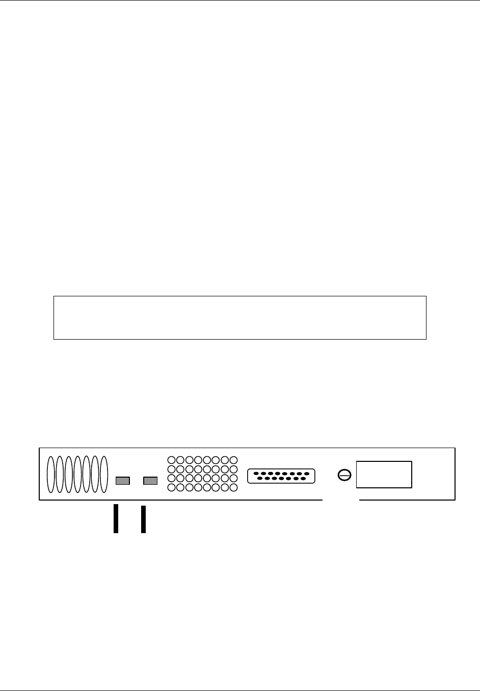
2.6.1.2 Hub Control Unit (HCU) Installation
The HCU, Keyboard, and Computer will take up one entire enclosure. For the outside
enclosure, these items are replaced with a network interface unit (PN 1000057G1) and the
HCU is remote from the outside enclosure. The following procedure is for the indoor
enclosure configuration.
NOTE
Both fixed and sliding sections of the keyboard slides are installed in the rack
at the factory. As part of the HCU installation, the sliding (keyboard tray)
section of each slide is removed from the rack and installed on the keyboard
tray.
a. Using a short cable tie, secure both touchpad cable and keyboard cable to cable tie
mount at rear of left slide.
b. Using six short cable ties, secure both touchpad cord and keyboard cable along
length of cable retractor. Do not over-stretch keyboard cable coils.
c. Locate two HCU rack-mounting brackets packed with HCU software media.
d. Remove hardware from bracket mounting holes on left and right sides toward front
of computer.
e. Using hardware removed, attach two brackets to chassis and tighten.
f. Insert computer into enclosure at location shown in Figure 2-4.
g. Slide computer onto angle rails and secure to rack using four 10-32 in. x .50
mounting screws and washers.
h. Connect keyboard cable to KEYBOARD connector at rear of HCU computer chassis
(Figure 2-5).
i. Connect touchpad cable to MOUSE connector at rear of HCU computer chassis
(Figure 2-5).
j. While supporting front and back of HCU monitor, carefully insert monitor into front
of rack at location shown in Figure 2-4.
k. Secure HCU monitor to rack using eight mounting screws and washers supplied
with monitor.
l. Connect HCU monitor video cable to video connector at rear of HCU computer
chassis (Figure 2-5).
TransCell 1900CB Installation Manual Document No. 1000070A
2-7
TRANSCEPT PROPRIETARY - DATA ON THIS PAGE SUBJECT TO RESTRICTIONS CITED ON COVER AND TITLE PAGE
HCU
Monitor
HCU
Computer
HCU
Keyboard
Tray Power
HDD
KB-LK
Reset
KB-LK
I
0
Figure 2-4. Typical Indoor Enclosure Configuration
KEYBOARD
MOUSE
LP
T 1
10base2
10base 5
10baseT
CO
M1
COM 2COM 1 COM 3
M
O
DE
M
C
A
R
COM 4
Connect Power Cable
to AC input connector
Connect Monitor Cable
to Video connector
Connect Keyboard Cable
to Keyboard connector
Connect the HIC Communication
Cable P1 to the RS-485 connector
Connect Touchpad Cable
to Mouse connector
Network Interface
Card (Ethernet)
PH
O
NE
LI
NE
BT
S
AL
AR
M
Figure 2-5. HCU Computer Rear View

TransCell 1900CB Installation Manual Document No. 1000070A
2-8
TRANSCEPT PROPRIETARY - DATA ON THIS PAGE SUBJECT TO RESTRICTIONS CITED ON COVER AND TITLE PAGE
2.6.1.3 +24 VDC Prime Power Installation
The +24 VDC interface for the Indoor Enclosures are terminal blocks located on the inside
of each enclosure on the upper rear panels. The terminal block accepts two wires (+24VDC
and RTN) and distributes the power through busbars. Wire sizes accepted by the terminal
block range from AWG #14 to AWG # 4.
a. Before connecting power to enclosure, ensure that internal or external +24 VDC
power is OFF.
b. Secure +24 VDC input wires from the Power Supply or external power source to
Input Terminal Block with compression screws. Using a flat blade screwdriver, back
off the two screws on input section of Input Terminal Block.
NOTE
For enclosures using the optional +24 VDC Power Supply, use power supply
output cable P/N 1000056G1 in place of the on-site external +24 VDC power
cabling.
2.6.1.4 Initial Prime Power Test
This test requires a multimeter capable of measuring +24 VDC, and associated test probes.
The external or internal +24 VDC supply should be energized at this time. Perform the
following procedure to verify the voltage:
Using a multimeter, measure and record busbar voltage. (The Enclosure/HIC data
sheet at the end of this manual may be reproduced and used for recording.) Verify that
voltage is between +20 and +28 VDC and that polarity matches labels on busbar
mounting brackets.
2.6.1.5 Initial HCU Test
a. At the HCU front panel, set monitor power switch to ON and observe that power
indicator lights. (The monitor power may be from the computer.)
b. Set computer power switch to ON and observe that power indicator lights. If
monitor is powered from computer, monitor power indicator will also light.
c. Observe that computer boots up within 45 seconds and monitor displays Windows
NT desktop screen.
d. Pull out keyboard tray and operate touchpad to verify cursor control.
e. Place cursor on Start button on Windows NT desktop and click left mouse button. A
pop up menu appears.
f. Place cursor on Shut Down … selection and click left mouse button. A
SHUTDOWN WINDOW dialog appears.
g. Click on Shut down the computer? Then click on Yes button. The computer begins
an orderly shutdown process. Wait until a screen message appears indicating that it
is safe to remove power from computer.

TransCell 1900CB Installation Manual Document No. 1000070A
2-9
TRANSCEPT PROPRIETARY - DATA ON THIS PAGE SUBJECT TO RESTRICTIONS CITED ON COVER AND TITLE PAGE
2.6.1.6 RF Interface Assembly (RFIA) Installation
NOTE
It is highly recommended that the RFIAs be installed in the enclosure in the
following order so that the enclosure does not become top-heavy and unstable
if the enclosure is not bolted to the floor:
• The first RFIA should be installed in the top slot of the lower enclosure
below the keyboard.
• RFIAs 2 and 3 should be installed starting in the slot just above the bottom
slot of the top enclosure followed by one in the top slot of the top enclosure.
a. Install RFIAs in enclosure by sliding them onto angle brackets and securing them
with screws and washers.
b. Repeat step a for remaining RFIAs.
c. Locate +24VDC Power Wiring Harness P/N 1000062G1 (Figure 2-7) for each RFIA.
d. At a location parallel to RFIA PWR connector, connect +24VDC connector of wiring
harness to +24VDC busbar and +24VRTN connector to +24VRTN busbar.
e. Plug mating connector of power cable into RFIA PWR connector and tighten
connector retaining screws.
f. Repeat steps d and e for remaining RFIAs.
2.6.1.7 Hub Fiber Interface (HFI) (Option)
a. Install HFIs in enclosure by sliding them onto angle brackets and securing them
with screws and washers.
b. Repeat step a for remaining HFIs.
c. Locate +24VDC Power Wiring Harness P/N 1000074G1 for each HFI.
d. At a location parallel to HFI PWR connector, connect +24VDC connector of wiring
harness to +24VDC busbar and +24VRTN connector to +24VRTN busbar.
e. Plug mating connector of power cable into HFI PWR connector and tighten
connector retaining screws.
f. Repeat steps d and e for remaining HFIs.
TransCell 1900CB Installation Manual Document No. 1000070A
2-10
TRANSCEPT PROPRIETARY - DATA ON THIS PAGE SUBJECT TO RESTRICTIONS CITED ON COVER AND TITLE PAGE
2.6.1.8 Hub Interface Converter (HIC) Installation
NOTE
It is highly recommended that the HICs be installed in the enclosure in the
following order so that the enclosure does not become top-heavy and unstable
if the enclosure is not bolted to the floor:
• The first HIC should be installed in the slot below the RFIA of the lower
enclosure below the keyboard.
• HICs 2 and 3 should be installed starting in the lower slot of the top
enclosure followed by one in the upper part of the top enclosure below the
RFIA.
a. Install HICs in enclosure by sliding them onto angle brackets and securing them
with screws and washers.
b. Connect one end of GND Cable Assembly P/N 1000060G1 to ground studs on the
enclosures located on the bottom panel of the enclosure and the other end on to the
wing nut screw on the back of the HIC.
c. Repeat steps a and b for remaining HICs.
d. Locate +24VDC Power Wiring Harness P/N 1000062G1 (Figure 2-7) for each HIC.
e. At a location parallel to HIC PWR connector, connect +24VDC connector of wiring
harness to +24VDC busbar and +24VRTN connector to +24VRTN busbar.
f. Plug mating connector of power cable into HIC PWR connector and tighten
connector retaining screws.
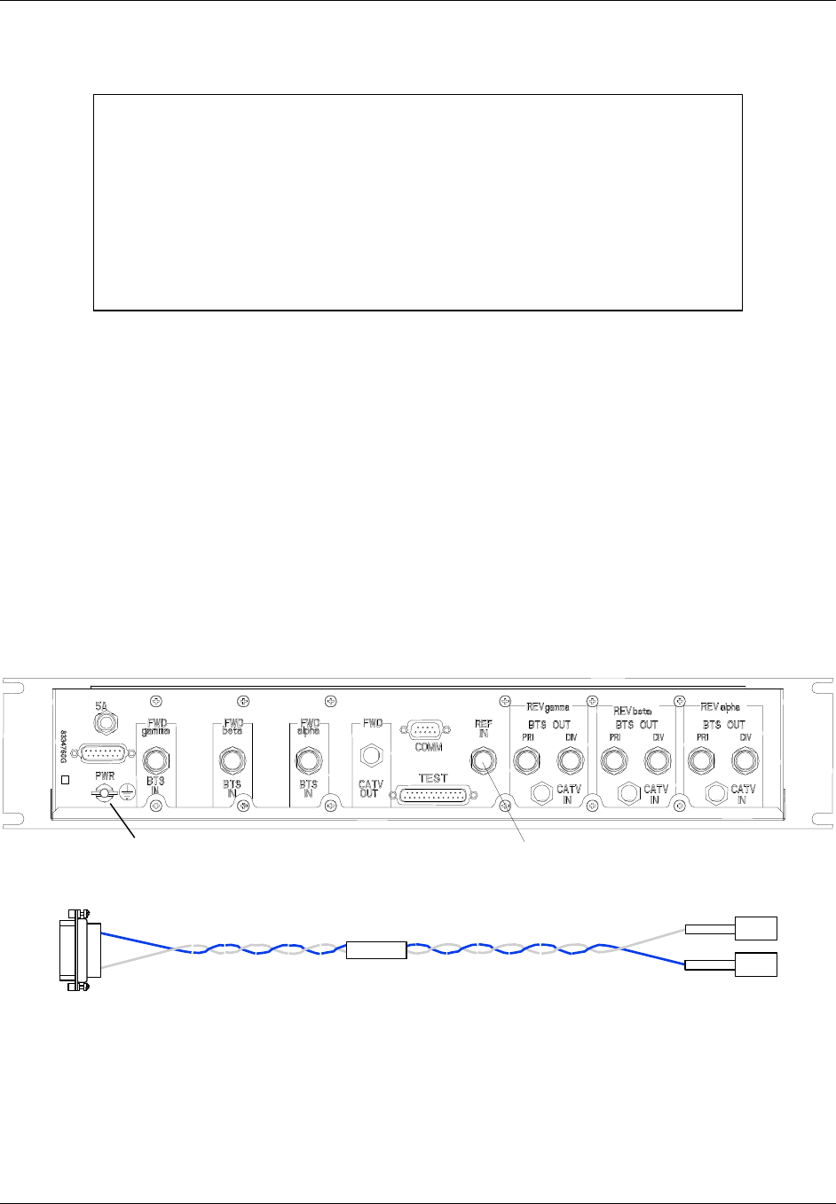
g. Repeat steps d and f for remaining HICs.
Ground Stud 10 or 15 MHz
Figure 2-6. HIC Rear Panel
8337944
+24RTN
+24VDC
P3
P1
P2
Figure 2-7. HIC Power Wiring Harness 1000062G1
TransCell 1900CB Installation Manual Document No. 1000070A
2-11
TRANSCEPT PROPRIETARY - DATA ON THIS PAGE SUBJECT TO RESTRICTIONS CITED ON COVER AND TITLE PAGE
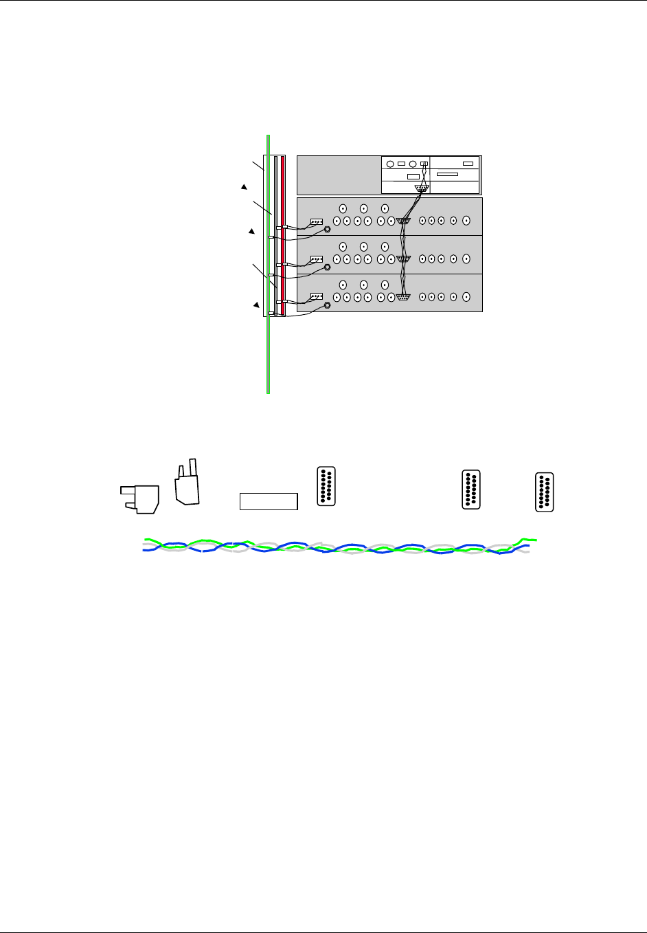
2.6.1.9 Digital Communications Wiring Installation
The HIC communicates with the computer via an RS-485 interface using a LonWorks®
protocol. The RS-485 interface uses twisted 3-wire 22-gauge wire, beginning at the
computer and connecting to the upper and lower HIC modules a RS-485 cable assembly PN
1000063G1. Figure 2-8.
CONTROL COMPUTER
LONWORKS
GND
BUSBAR
+24VDC
BUSBAR
+24VDC
RTN
BUSBAR
Figure 2-8. Three HIC Control Interconnect Diagram (not to scale)
a. Mate connector P1 of HIC Communication Wiring Harness P/N 1000063G1 (Figure
2-9) to RS-485 port on computer rear panel (Figure 2-5).
1000063
Figure 2-9. HIC Communication Wiring Harness P/N 8339969G1
b. Connect the other connector to the additional HICs.
2.7 HUB EQUIPMENT CABLE INSTALLATION
With the exception of the indoor and outdoor interface cables between the RFIA and HIC
and between the HIC and HFI, external RFIA interface cables are not provided with the
enclosures or HICs. The cables are provided locally by the user at the installation site. For
the Hub Equipment enclosures, the user must provide up to 14 cables for each RFIA/HIC
installed:
One cable to interface the 15 MHz Reference to the HIC (if using external reference), four
cables interface the HIC with the coaxial network (if applicable), three fiber cables
interface the HFI with the fiber network (if applicable), and nine cables interface the RFIA
with the BTS. Figure 2-10 shows the RF cable interconnections between a single installed
HIC, an RFIA, coaxial network, and BTS. If the HFI is required, configure the cables
between the HIC and HFI to meet the fiber network architecture.
TransCell 1900CB Installation Manual Document No. 1000070A
2-12
TRANSCEPT PROPRIETARY - DATA ON THIS PAGE SUBJECT TO RESTRICTIONS CITED ON COVER AND TITLE PAGE
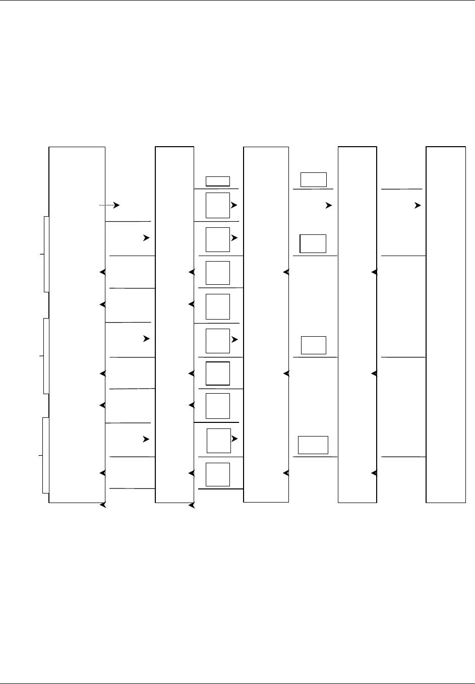
2.7.1 10/15 MHz Reference cable Installation between RFIA and HIC
a. Connect a RF cable (PN 1000066G1) to 15-MHz output of RFIA and route cable to
vicinity of HIC. Do not connect cable at this time.
b. Measure power level at output of cable. Verify that 15 MHz output level from RFIA
is between 0 and -16 dBm.
c. Record measured power level (the Enclosure/HIC data sheet at the end of this
manual may be reproduced and used for recording).
d. Connect cable to Ref In port on HIC after level has been verified and recorded.
HIC
FWD
Alpha
BTS
IN
REF IN
REV
Alpha
BTS OUT
PRI
REV
Alpha
BTS OUT
DIV
Coaxial
Network
REV LINK
REV LINK
FWD LINK
REV LINK
FWD
IN/OUT
REV
Alpha
IF IN
REV
Beta
IF IN
REV
Gamma
IF IN
BTS
1.9 GHZ FORWARD
1.8 GHZ REVERSE PRI
1.8 GHZ REVERSE DIV
FWD
Beta
BTS
IN
REV
Beta
BTS OUT
PRI
REV
Beta
BTS OUT
DIV
FWD
Gamma
BTS
IN
REV
Gamma
BTS OUT
PRI
REV
Gamma
BTS OUT
DIV
ALPHA
BETA
GAMMA
1.9 GHZ FORWARD
1.8 GHZ REVERSE PRI
1.8 GHZ REVERSE DIV
1.9 GHZ FORWARD
1.8 GHZ REVERSE PRI
1.8 GHZ REVERSE DIV
RFIA RFIA
15 MHz15 MHz Optional
Figure 2-10. BTS/HIC/Coaxial Network RF Cabling Diagram (15MHz from RFIA shown)

TransCell 1900CB Installation Manual Document No. 1000070A
2-13
TRANSCEPT PROPRIETARY - DATA ON THIS PAGE SUBJECT TO RESTRICTIONS CITED ON COVER AND TITLE PAGE
2.7.2 Remote User Interface
The HCU computer provides four general purpose RS-232 serial ports to be used to
facilitate remote access and control of the HCU graphical user interface. These interfaces
may be used to connect to a NOCC. The ports are located on the HCU computer rear panel
(Figure 2-5):
♦ Com1: RS-232
• Supports a data rate of up to 9600 bps
• Read Only Port (ROP)
• All messages are in ASCII text message format
• Used to transmit alarms to the NOCC on an unsolicited basis
♦ Com2: RS-232
• Supports a data rate of up to 9600 bps
• Read/Write Port (RWP)
• All messages are in ASCII text message format
• Handles the remote operator interaction
• Receives remote operator queries and control messages
• Transmits status and statistics back to remote operator
♦ Com3: RS-232
• Supports a data rate of up to 9600 bps
• General purpose port for remote graphical user interface
♦ Com4: Growth
• Supports a data rate of up to 9600 bps
• General purpose port for remote graphical user interface
2.7.3 HCU Modem
The HCU computer is provided with an internal modem, which supports a data
transmission rate of up to 56 kbps. This interface may be used to connect to a NOCC
through a phone line. The modem connectors (Phone, Line) are located on the rear panel of
the HCU computer (Figure 2-5).

TransCell 1900CB Installation Manual Document No. 1000070A
2-14
TRANSCEPT PROPRIETARY - DATA ON THIS PAGE SUBJECT TO RESTRICTIONS CITED ON COVER AND TITLE PAGE
2.8 INSTALLATION CHECKOUT - INITIAL TURN-ON
These installation checkout procedures provide a confidence check of the TransCell 1900CB
Hub equipment before interfacing it with the BTS. These procedures should be performed
prior to installing any CMIs. BTS interfacing and network optimization is covered in
Section 4 of this manual.
2.8.1 Reverse Link Input from Network Infrastructure
This procedure checks the power level of the reverse link input signal from the fiber/coaxial
plant to each HIC sector.
a. Connect a reverse link RF cable from an appropriate alpha sector reverse link
device in Hub enclosure and route cable to selected HIC.
b. Connect cable to REV alpha CATV IN port on rear panel of selected HIC.
c. Repeat steps a through d for reverse link beta and gamma sectors.
NOTE
To minimize disturbance of HIC cables that have already been routed and
tied at the rear of the rack, it is recommended that each HIC be electrically
checked after it is installed, before proceeding to the next HIC installation.
d. Continue to paragraph 2.8.2 to verify HIC operation before proceeding with cabling
for next HIC installation.

TransCell 1900CB Installation Manual Document No. 1000070A
2-15
TRANSCEPT PROPRIETARY - DATA ON THIS PAGE SUBJECT TO RESTRICTIONS CITED ON COVER AND TITLE PAGE
2.8.2 HIC Initial Turn-on and Communication Test
a. Verify that power switches on all HICs, computer, and monitor are OFF.
b. Verify that +24 VDC BUSBAR PWR.
c. If installed, set the +24 VDC Power Supply power switch to ON and observe that
the power supply indicates +24 VDC on meter.
NOTE
The HIC data sheet at the end of this manual may be reproduced and used
for recording the measured levels specified in the following procedures.
d. Set computer and monitor power switches to ON position.
e. Extend keyboard tray.
f. Set front panel PWR switch, of first HIC to 1 (ON) and verify that green front panel
PWR indicator lights.
g. Observe that HIC front panel LEDs blink and remain off. Normal indications for
these LEDs are as follows:
ID Lights to identify activated HIC (acquired by HCU software)
FAULT Lights to indicate a operational fault in HIC
COMM Flashes to indicate communications between HIC and CMI; if
indicator is continuously lit, probable fault in HIC
h. Repeat step f. and g. for remaining installed HICs.
i. Set HIC front panel PWR switch to 0 (OFF) on all HICs.
j. Set both computer and the monitor power switches to OFF.
2.8.3 HCU Setup for HIC Checkout
a. Using touchpad, select HCU Control Panel icon in Program Group.
b. Observe that CONFIGURATION OPTIONS dialog (Figure 2-11) appears on
monitor.
c. Click No to accept default system configuration and display HUB CONTROL
PANEL dialog.
d. Observe that HUB CONTROL PANEL: USER dialog (Figure 2-12) appears on
monitor.
e. At HUB CONTROL PANEL: USER dialog, select Privileges/Increase Privileges
from menu bar. HCU SYSTEM ACCESS dialog appears.
f. Enter Super-User password and click OK to return to HUB CONTROL PANEL
dialog. Verify that dialog title bar now reads HUB CONTROL PANEL: SUPER-
USER.
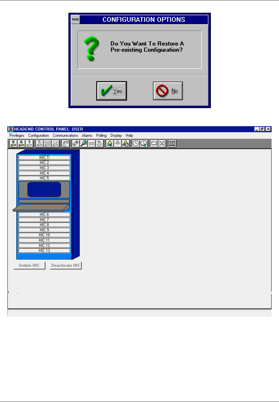
TransCell 1900CB Installation Manual Document No. 1000070A
2-16
TRANSCEPT PROPRIETARY - DATA ON THIS PAGE SUBJECT TO RESTRICTIONS CITED ON COVER AND TITLE PAGE
Figure 2-11. CONFIGURATION OPTIONS Dialog
Figure 2-12. HUB CONTROL PANEL: USER Dialog

TransCell 1900CB Installation Manual Document No. 1000070A
2-17
TRANSCEPT PROPRIETARY - DATA ON THIS PAGE SUBJECT TO RESTRICTIONS CITED ON COVER AND TITLE PAGE
2.8.4 HIC Activation
This procedure, also referred to as HIC acquisition, adds the selected HIC to the database
for monitoring and control by the HCU. The procedure also shows that the HIC and HCU
are communicating and that all cable interconnections are satisfactory.
a. On selected HIC, set front panel power switch to 1 (ON).
b. Observe that PWR indicator is lit and ID, FAULT, and COMM indicators are not lit.
c. At HUB CONTROL PANEL: SUPER-USER dialog (Figure 3-5 of O&M manual),
double-click on numbered panel (HIC 1–HIC 13) representing HIC to be activated.
d. Observe that ADD HIC dialog (Figure 2-13) appears.
e. Type data in following boxes (do not press enter):
Enter Neuron ID using 12 Hexadecimal characters (required)
Enter Cell ID (Optional reference data)
Enter Serial Number of HIC (Optional reference data)
f. Type in Reverse Frequency values for Alpha/Beta/Gamma sectors. Minimum
spacing between Primary and Diversity values is 2 MHz, maximum is 4.75 MHz for
a single carrier system and 5.5MHz for a three carrier system. Overall range is 5 to
52 MHz or 5 to 42 MHz, depending on Power Extractor configuration in the CMIs.
This range can be set in 0.25-MHz increments.
g. Type in Forward Channel number: Range 62–94, 100–116.
h. Type in desired PCS Frequency: Range 1930–1990 MHz in 0.05 MHz steps.
i. Set following options to indicated position:
Power Output (Enable/Disable)
Reference Tone (Enable/Disable)
Control Tone (Enable/Disable)
Reset (Defaults/Last Values)
j. Click OK to add new HIC.
k. Verify that HUB CONTROL PANEL dialog appears and that numbered panel icon
representing added HIC appears in green.
NOTE
A non-green, flashing HIC icon indicates an alarm. Alarm information may
be viewed by selecting Alarms/Show Unacknowledged Alarms from the
HUB CONTROL PANEL menu bar. Table 4-2 in this manual provides a
complete list of alarms.
l. Observe that ID indicator blinks on front panel of selected HIC.
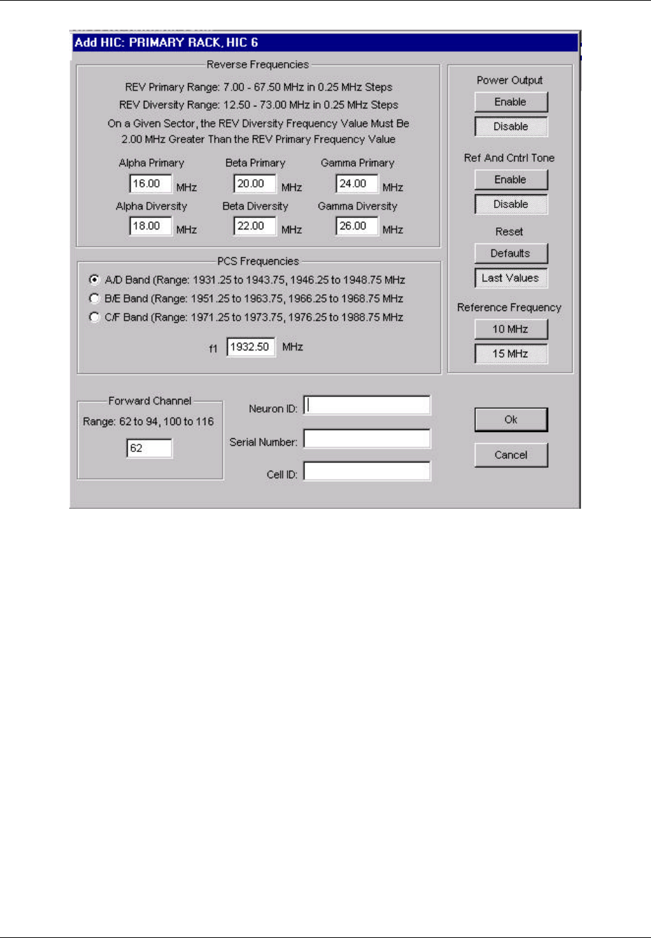
TransCell 1900CB Installation Manual Document No. 1000070A
2-18
TRANSCEPT PROPRIETARY - DATA ON THIS PAGE SUBJECT TO RESTRICTIONS CITED ON COVER AND TITLE PAGE
Figure 2-13. Typical ADD HIC Dialog

TransCell 1900CB Installation Manual Document No. 1000070A
2-19
TRANSCEPT PROPRIETARY - DATA ON THIS PAGE SUBJECT TO RESTRICTIONS CITED ON COVER AND TITLE PAGE
2.8.5 HIC Reference and Control Tone Output
This procedure measures and sets the Reference and Control Tone levels at the HIC
FORWARD TEST POINT (10 dB down). At the REFERENCE AND CONTROL TONE
dialog (Figure 2-14), set the Attenuator Setting such that the power level is initially -14
dBm at the test point (-4 dBm at the HIC FWD CATV OUT port).
a. Connect a Spectrum Analyzer to the FORWARD TEST POINT (75-Ohm).
b. Set Spectrum Analyzer as follows:
Center Frequency: Ch.62 = 453 MHz; typical
Scale: 10 dB/div
Span: 8 MHz
Peak Search or Set Marker to:
Single Carrier System:
? HIC Reference signal at lower end of signal spectrum (Ch.62 = 450.85
MHz) and adjust HIC Reference attenuator in step c.
? HIC Control signal at upper end of signal spectrum (Ch.62 = 455.05
MHz) and adjust HIC Control attenuator in step c.
Multiple Carrier System:
? HIC Reference signal at lower end of signal spectrum (Ch.62 = 450.05
MHz) and adjust HIC Reference attenuator in step c.
? HIC Control signal at upper end of signal spectrum (Ch.62 = 455.85
MHz) and adjust HIC Control attenuator in step c.
c. Determine HIC Reference and Control Tone Output Level and set to -14 dBm at
FORWARD TEST POINT:
Maximum Output Level = -9 dBm
Minimum Output Level = -19 dBm
d. Record and save the attenuator settings.
e. Final power level adjustment for integration with the forward link should be
completed using external 75Ω attenuator pads on the power extractor or adjustable
trim pot on internal fiber unit within the CMI.
f. Connect HIC FWD CATV output to the coaxial network forward link when the
proper levels are set.
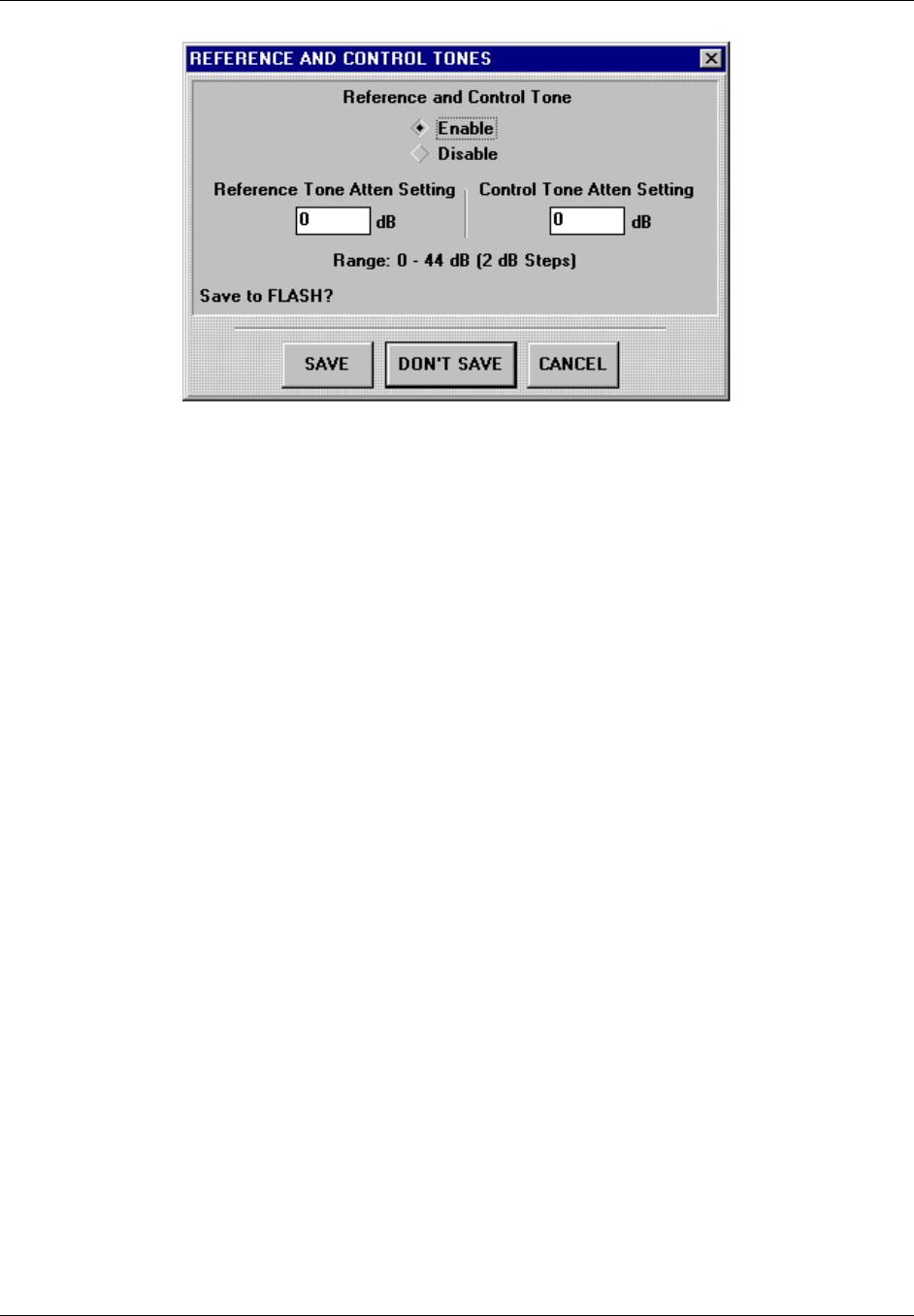
TransCell 1900CB Installation Manual Document No. 1000070A
2-20
TRANSCEPT PROPRIETARY - DATA ON THIS PAGE SUBJECT TO RESTRICTIONS CITED ON COVER AND TITLE PAGE
Figure 2-14. REFERENCE AND CONTROL TONES Dialog

TransCell 1900CB Installation Manual Document No. 1000070A
3-1
TRANSCEPT PROPRIETARY - DATA ON THIS PAGE SUBJECT TO RESTRICTIONS CITED ON COVER AND TITLE PAGE
SECTION 3.
CMI INSTALLATION
3 CMI INSTALLATION
3.1 CMI INSTALLATION REQUIREMENTS
Installing the Cable Microcell Integrator (CMI) involves these major tasks:
♦ Determining the physical site location for the CMI
♦ Selecting the CMI configuration required
♦ Installing the CMI with attaching antennas fiber, and cables
♦ Performing CMI electrical checks
♦ Activating CMI
NOTE
The CMI FWD channel needs to be set to the desired HIC IF operating
channel prior to activation of the CMI. This can be completed prior to
installation using the appropriate power (110/220 VAC) and the CMI
Initialization Tool, or by using the CMI Initialization Tool after power has
been connected during installation. For initial deployment this may be
completed at the HIC and GUI.
Prior to starting the installation procedure, locate and remove the 4-inch by
4-inch removable bar-code label from the CMI carton, and attach it to the
Installation Work Order or other appropriate documentation. This label
includes critical identification data, which will be required to activate the
CMI after installation.
3.1.1 Tools, Test Equipment and Supplies
Table 3-1 lists the tools and test equipment needed to support the CMI installation.
Table 3-1. CMI Installation Support Needs
Hand Tools
Wrench, 1/2 inch hex socket for CMI Cover bolts
Wrench, torque (145 in-lb), 1/2-inch for CMI Hinged Cover
Wrench, open-end 1/2-inch, for Seizure Screw Access Port
Wrench, torque (30 in-lb), 3/4-inch
Screwdriver, flat blade, medium, for Power Extractor mounting screw and 75-Ohms port seizure
screws (Coaxial Installation)
Nut Driver ¼ inch for 75-Ohms port seizure screws (Coaxial Installation)
Long Reach Test Point Adapter, Antec No. SCI 039719 or equivalent (Coaxial Installation)
Gilbert Fiber Interface Adapter (Gilbert No. NS7270-n;1,5,9,or 11) (Fiber Installation)
Test Equipment
Hand-held Digital Multimeter with test probes
Stealth meter, or equivalent
TransCell 1900CB Installation Manual Document No. 1000070A
3-2
TRANSCEPT PROPRIETARY - DATA ON THIS PAGE SUBJECT TO RESTRICTIONS CITED ON COVER AND TITLE PAGE
3.1.2 CMI Configurations
The TransCell 1900CB CMI is available in 12 major different configurations, based on the
combination of the Power Extractor, Fiber Optic Module, and PCS frequency band
selections. The CMI configurations are listed in Table 3-2.
Table 3-2. CMI Configurations
Part Number Configuration Description
1000000G1-G11 CMI Assembly A/D Band, Single FA, Fiber Unit
1000000G12-G22 CMI Assembly B/E Band, Single FA, Fiber Unit
1000000G23-G33 CMI Assembly C/D Band, Single FA, Fiber Unit
1000501G1-G2 CMI Assembly A/D Band, Single FA, Coaxial Unit
1000501G3-G4 CMI Assembly B/E Band, Single FA, Coaxial Unit
1000501G5-G6 CMI Assembly C/D Band, Single FA, Coaxial Unit
1000601G1-G11 CMI Assembly A/D Band, Three FA, Fiber Unit
1000601G12-G22 CMI Assembly B/E Band, Three FA, Fiber Unit
1000601G23-G33 CMI Assembly C/D Band, Three FA, Fiber Unit
1000701G1-G2 CMI Assembly A/D Band, Three FA, Coaxial Unit
1000701G3-G4 CMI Assembly B/E Band, Three FA, Coaxial Unit
1000701G5-G6 CMI Assembly C/D Band, Three FA, Coaxial Unit
3.1.3 Transcept-Furnished Items for CMI Installation
Each CMI is shipped with two Hanger Bracket Assemblies 1000503G1 for cable strand
installation. Any additional required mounting hardware is provided by the customer. The
items listed in Table 3-3 are optionally available from Transcept.
Table 3-3. Optional Transcept-Furnished Items for CMI Installation
Configuration Description Qty
Antenna Assembly, Receive (2), Transmit (1), 6 dBi 3
Cable Assembly, Receive, 50 ohms, Type N (male) connector 3m length 2
Cable Assembly, Transmit, 50 ohms, Type N (male) connector 2m length 1
3.1.4 Customer-Furnished Items for CMI Installation
Table 3-4 lists the customer-furnished equipment required to complete the CMI
installation. Before proceeding with the CMI installation, inventory the items listed in
Table 3-3 (if not furnished by Transcept) and Table 3-4 to ensure all necessary parts are
available for installation.

TransCell 1900CB Installation Manual Document No. 1000070A
3-3
TRANSCEPT PROPRIETARY - DATA ON THIS PAGE SUBJECT TO RESTRICTIONS CITED ON COVER AND TITLE PAGE
Table 3-4. Customer-Furnished Items for CMI Installation
Nomenclature Qty
RF Cable from coaxial network (Coaxial Installation) 1*
Fiber Cable from fiber network (Fiber Installation) 1
75 Ohms Directional Coupler or tap (coaxial installation)
Optical Splitter (fiber installation)
Prime Power Cable (fiber installation)
1
*One or both cables, depending on installation requirements, 75 ohm, 5/8-inch 24-
thread male connector
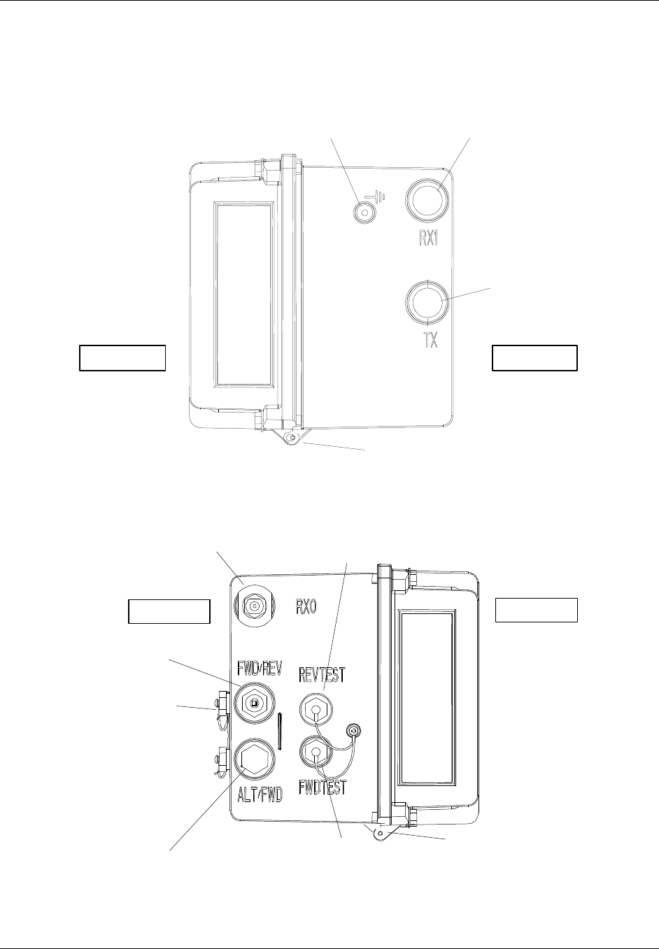
TransCell 1900CB Installation Manual Document No. 1000070A
3-4
TRANSCEPT PROPRIETARY - DATA ON THIS PAGE SUBJECT TO RESTRICTIONS CITED ON COVER AND TITLE PAGE
3.1.5 CMI External Connector Identification
Figure 3-1 and Figure 3-2 show the locations of the CMI external connectors. Table 3-5
briefly describes the purpose of each external connection point.
Threaded
Ground Port Diversity Receive
Antenna Connector
Transmit
Antenna
Connector
Cover Hinge
ROAD SIDE CURB SIDE
Figure 3-1. CMI Chassis Right End View
Primary Receive
Antenna Connector Test Point
Access Port (coax) or
Fiber In/Out (fiber)
Test Point
Access Port (coax) or
Power Port (fiber)
Power Port or N.C.
Cable Port
CATV Port
Seizure Screw
Access Ports
Cover Hinge
CURB SIDE ROAD SIDE
Figure 3-2. CMI Chassis Left End View

TransCell 1900CB Installation Manual Document No. 1000070A
3-5
TRANSCEPT PROPRIETARY - DATA ON THIS PAGE SUBJECT TO RESTRICTIONS CITED ON COVER AND TITLE PAGE
Table 3-5. CMI External Connections
Connection Point Description
Threaded Grounding Point 10-32 in. x 1/2-inch hole tapped into a boss, to secure a
ground wire to Protective Earth grounding point. (Protective
Earth is a UL/NRTL term.) See paragraph 3.3.5.4.
RX0 Primary Receive
Antenna Connector Primary receive antenna connection; Type N (male), 50 ohm
connector
TX Antenna Connector Transmit antenna connection; Type N (male), 50 ohm
connector
RX1 Diversity Receive
Antenna Connector Diversity receive antenna connection; Type N (male), 50 ohm
connector
REVTEST, FWDTEST
Test Point Access Ports Provides probe access for measuring reverse link and forward
link signal levels for coaxial CMIs. Weather-protected by
15/16-inch hex cover caps. Provide power inputs and fiber
inputs for fiber CMIs. See paragraph 3.4.
CATV Port Seizure Screw
Access Ports Access for tightening seizure screws on 75-Ohms Connector
center conductors. See paragraph 3.3.2.1.
CATV Cable Ports Tapped holes provided for customer-supplied KS type
adapters; see paragraph 3.3.2.1. The other port is used for
power input for a coaxial installation.
3.2 SITE PREPARATION
The following paragraphs are provided for information and guidance for the CMI Assembly
installation. At the site, the installer must:
♦ Determine the CMI location on the messenger strand.
♦ Determine the CMI power configuration required for the CMI installation site.
♦ For installing the customer furnished-equipment, the installer should reference the
internal procedures for general, overhead, and underground installation of the
telecommunications components.
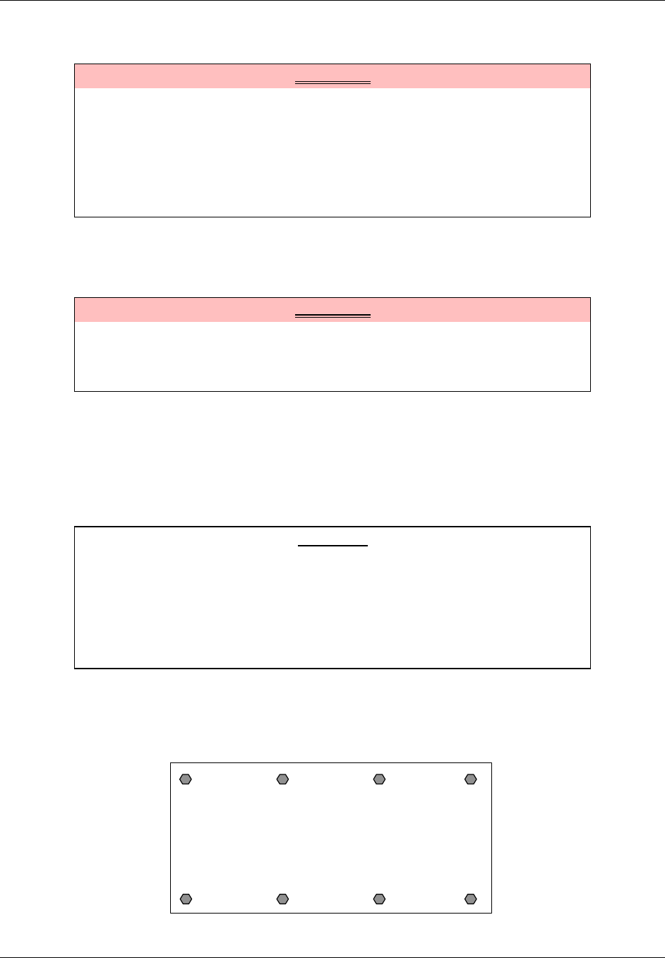
TransCell 1900CB Installation Manual Document No. 1000070A
3-6
TRANSCEPT PROPRIETARY - DATA ON THIS PAGE SUBJECT TO RESTRICTIONS CITED ON COVER AND TITLE PAGE
3.3 CMI HARDWARE INSTALLATION GUIDE
WARNING
Potentially dangerous High Voltage exists on the AC power cable to the CMI
Assembly that could cause bodily injury or even death. During a line surge or
fault condition, High Voltage also could be present on the antenna
connectors. Use extreme care and required safety precautions while working
on the CMI installation and handling the AC power cable.
To avoid any chance of overexposure to RF emissions when working near a
CMI, maintain a minimum distance of 12 in. from the transmitting antenna.
3.3.1 CMI Access
3.3.1.1 Opening the Assembly
WARNING
The CMI hinged cover (roadside) contains the Power Supply and therefore is
heavy. If a CMI must be opened in the installed position, always support the
cover with one hand when releasing the last captive screw to avoid
equipment damage and/or personal injury.
The hinged CMI Assembly housing is secured with eight captive bolts. Place the CMI on
any firm surface and release the bolts, using a 1/2-inch socket wrench. Open the cover
carefully, keeping in mind that the cover (roadside) portion contains the Power Supply and
therefore is heavy.
3.3.1.2 Closing the Assembly
CAUTION
When closing the CMI Assembly, ensure that all internal wiring is clear of
the housing seal before securing captive screws to avoid possible equipment
damage.
NOTE
To restore the watertight seal on a CMI Assembly, the captive bolts must be
torqued to 140–145 in-lb, in the proper sequence.
Place the CMI Assembly on any firm surface. Carefully close the cover, ensuring that all
internal wiring is clear of the housing seal. Torque the eight captive bolts to 140–145 in-lb
in the sequence shown in Figure 3-3.
CMI Cover
Closed
1
2
3
5
4 6
7
8
Figure 3-3. CMI Bolt Tightening Sequence
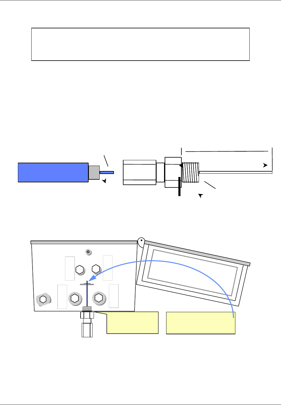
TransCell 1900CB Installation Manual Document No. 1000070A
3-7
TRANSCEPT PROPRIETARY - DATA ON THIS PAGE SUBJECT TO RESTRICTIONS CITED ON COVER AND TITLE PAGE
3.3.2 CMI Port and Power Extractor Configuration Options
NOTE
If the installation site requires an alternate CMI configuration, it is strongly
recommended that the changes be made on the ground prior to installing the
CMI on the cable strand.
3.3.2.1 CMI Coxial Configurations
There is Coaxial CMI configurations uses either a housing-to-F adapter or a housing-to-
hardline connector (shown in Figure 3-4). One or both ports are used, based on installation
requirements. The housing-to-F adapter or the housing-to-hardline connector is threaded
into the CMI housing, with its center conductor secured and connected to the internal CMI
circuits by a seizure screw. The procedure for cutting the center conductor to proper length
is shown in Figure 3-5. The seizure screw is accessed by removing a threaded plug located
at the rear of the CMI chassis (curbside). The seizure screw is tightened using a medium
flat-blade screwdriver or a ¼-inch nut driver.
5/8 in. x 24 THREAD
ADAPTER
75 Ohms COAX (HARDLINE)
CENTER CONDUCTOR
LENGTH DETERMINED
BY HOUSING ADAPTER PROBE DEPTH
(in inches)
1.7 MIN, 1.9 MAX
Figure 3-4. Typical Housing-to-Hardline Connector Interface
FWD/REV
ALT/FWD
REVTEST
FWDTEST
RX0
1. Butt shoulder of
connector against
bottom of CMI housing
2. Rest cutting tool on top of
embossed cut line and clip
center conductor to length
Figure 3-5. Procedure for Cutting Coaxial Center Conductor to Length
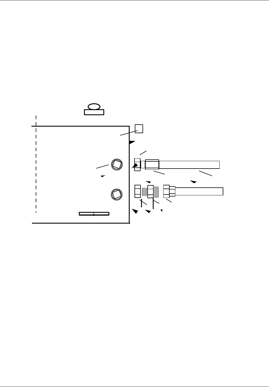
TransCell 1900CB Installation Manual Document No. 1000070A
3-8
TRANSCEPT PROPRIETARY - DATA ON THIS PAGE SUBJECT TO RESTRICTIONS CITED ON COVER AND TITLE PAGE
The coaxial CMI configuration uses the FWD/REV port for the RF signal interface. The
other ALT/FWD port is used to supply source power to the unit (110/220VAC).
If the installation requirements dictate the use of housing-to F-adapter(s), it is strongly
recommended that the adapter installation be performed on the ground prior to installing
the CMI on the cable strand.
The assembly sequence of 75-ohms coax and housing-to-hard-line adapter to CMI is
determined by mechanical constraints. Figure 3-6 shows an exploded view of these items.
The housing-to-hard-line adapter must be threaded into the CMI housing; therefore, it
must be separate from the 75-ohms coax during installation or removal. The seizure screw
is tightened against the housing-to-hard-line adapter center conductor after the adapter is
installed. The 75-ohms coax is joined to the housing-to-hard-line adapter after the adapter
is secured to the CMI. The adapter must be torqued to 30 in-lb.
SEIZURE SCREW
ACCESS PORTS 75 OHMS
COAX
ADAPTER
75-OHMS CONNECTED
TO
FWD/REV PORT
ALT/FWD PORT
CMI CHASSIS OUTSIDE
PARTIAL REAR VIEW
RX0 PRIMARY RECEIVE
ANTENNA CONNECTOR
Power Connector
Figure 3-6. Assembly of Typical Housing to Hard-line/Power Connectors

TransCell 1900CB Installation Manual Document No. 1000070A
3-9
TRANSCEPT PROPRIETARY - DATA ON THIS PAGE SUBJECT TO RESTRICTIONS CITED ON COVER AND TITLE PAGE
3.3.2.2 Power Extractor Options
This document uses the terms single interface mode (also referred to as the combined
interface mode) in describing how the CMI is interfaced to the 75 Ohms coaxial network.
These terms are further defined as follows:
The CMI Power Extractor module is available in the configuration, as defined below:
♦ Single Interface Mode with frequency ranges as follows:
• Basic Frequency Range or Sub-Split - 5 to 42 MHz
• Extended Frequency Range or Mid-Split - 5 to 52 MHz1
The Power Extractor module is shown in Figure 3-7. The outward appearance of the two
configurations are identical except for the serial number. The eighth digit from the left of
the serial number is always 1 for the single interface mode (basic frequency range)
configuration; always 2 for the single interface mode (extended frequency range)
configuration. (The seventh digit from the left of the Power Extractor serial number is
always 2). For example, serial number 989T00210000 indicates a single (combined)
interface mode (basic frequency range) configuration.
The Power Extractor accommodates field-replaceable, plug-in attenuator pads for both the
forward and reverse coaxial paths, and a field-replaceable, plug-in equalizer in the forward
coaxial path (typically, the equalizer is set to 0dB). These component locations are
accessible when the CMI housing cover is open without the need to remove the Power
Extractor. The CMI is shipped with no pads or equalizer installed. It will accept Scientific
Atlanta model number PP-0 to PP-10 attenuator pads or equivalents and Scientific Atlanta
model number EQ750 equalizers or equivalents. For typical installations, either
configuration of the Power Extractor will meet the requirements.
1 With this Power Extractor configuration, no other forward link services are allowed below 150 MHz.
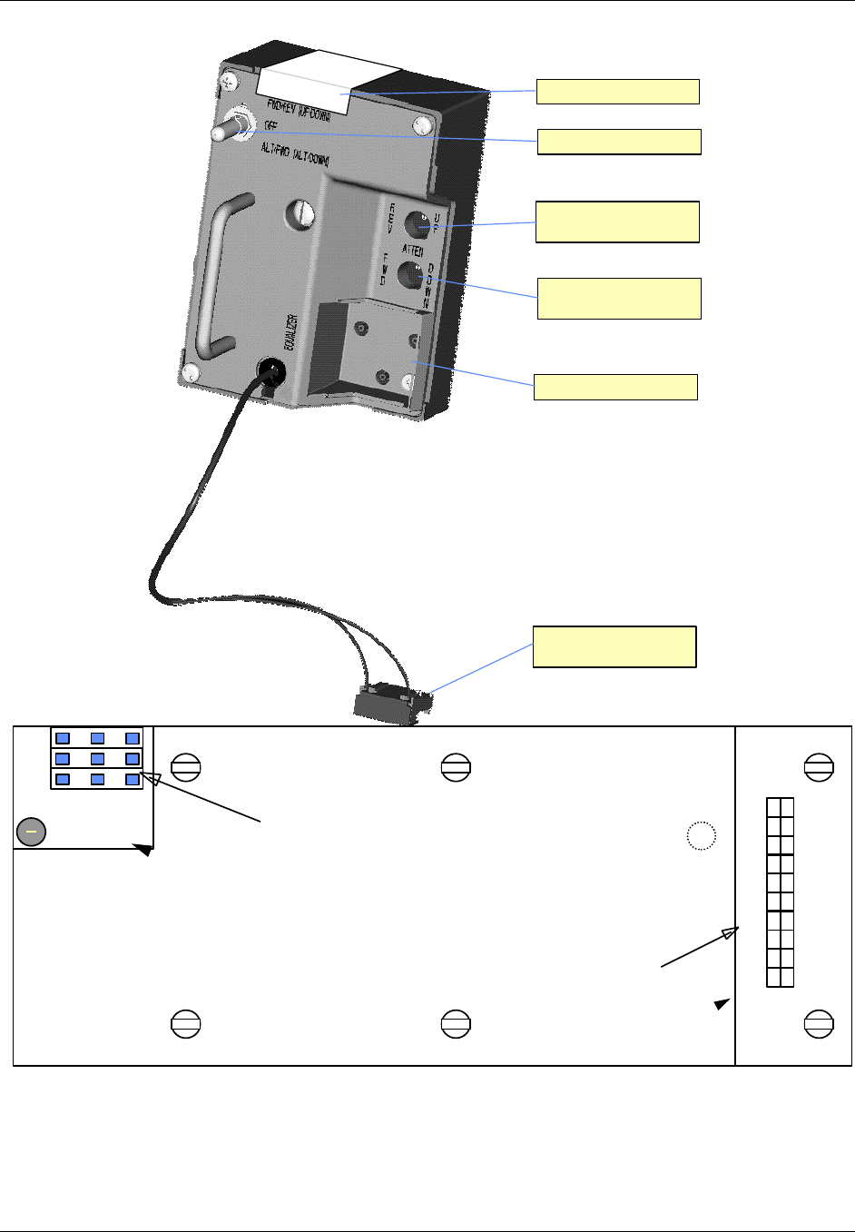
TransCell 1900CB Installation Manual Document No. 1000070A
3-10
TRANSCEPT PROPRIETARY - DATA ON THIS PAGE SUBJECT TO RESTRICTIONS CITED ON COVER AND TITLE PAGE
Power Selection Switch
Reverse Link Attenuator
Pad Plug-In
Connector no longer used
Forward Link Attenuator
Pad Plug-In
Equalizer Pad Plug-In
Serial No. Location
BAR CODE
SERIAL NUMBER
Figure 3-7. Power Extractor
DC CONNECTOR
AC INPUT CONNECTOR
Ntrl
Line
LED
Earth
Fuse
+5
+15
+25
+25
+25
-15
NC
+5
+15
-15
C
O
M
M
O
N
R
E
T
U
R
N
S
Figure 3-8. Power Supply Input Connector

TransCell 1900CB Installation Manual Document No. 1000070A
3-11
TRANSCEPT PROPRIETARY - DATA ON THIS PAGE SUBJECT TO RESTRICTIONS CITED ON COVER AND TITLE PAGE
3.3.3 Coaxial or Fiber Network Interface to the CMI
A coaxial network typically connects to the CMI through a 75 Ohms tap or coupler. The
tap or coupler is selected by the required loss between the Hub and the CMI at that
location.
A fiber network typically connects to the CMI in a similar manner as a coaxial network.
The fiber drop is coupled in to the network via a fiber splice. The operational range of the
fiber CMI (10 to 20 dBo; Hub to/from CMI) determines the coupled value required. The
fiber passes through the CMI housing via a Gilbert connector (PN NS7270-n; 1,5,9,or 11) or
equivalent.
3.3.4 Power Extractor Reverse Link/Forward Link RF Attenuation (Coaxial Installation)
The Power Extractor plugs into the CMI chassis and Connector Plate. It is secured by one
captive screw. As shown in Figure 3-7, the Power Extractor contains two plug-in
attenuator pad receptacles, one for adding reverse link attenuation and one for adding
forward link attenuation. It also includes a plug-in equalizer receptacle for forward path
equalization.
The Power Extractor is shipped with no pads or equalizer installed. It is recommended that
both attenuation and equalization values be initially set to 0 dB. The pad receptacles will
accept Scientific Atlanta model numbers PP-0 to PP-10 attenuator pads or equivalent. The
changing of pad values is discussed as part of the installation adjustments in paragraphs
3.5. The equalizer receptacle will accept Scientific Atlanta model number EQ750 equalizers
or equivalent. (Pads and equalizers may be provided by Transcept at the initial
installation, at customer request.)
3.3.5 Installing the CMI
3.3.5.1 Attaching CMI to Messenger Strand
CMI Bracket Assembly 1000503G1 is provided with the CMI. These brackets secure the
CMI Assembly approximately three inches below the messenger strand. It is recommended
that the brackets be secured to the CMI before ascending to the cable strand. The washer,
lock washer and bolt supplied with the bracket are assembled in the order shown in Figure
3-9. Recommended torque range is 75 to 90 in-lb.
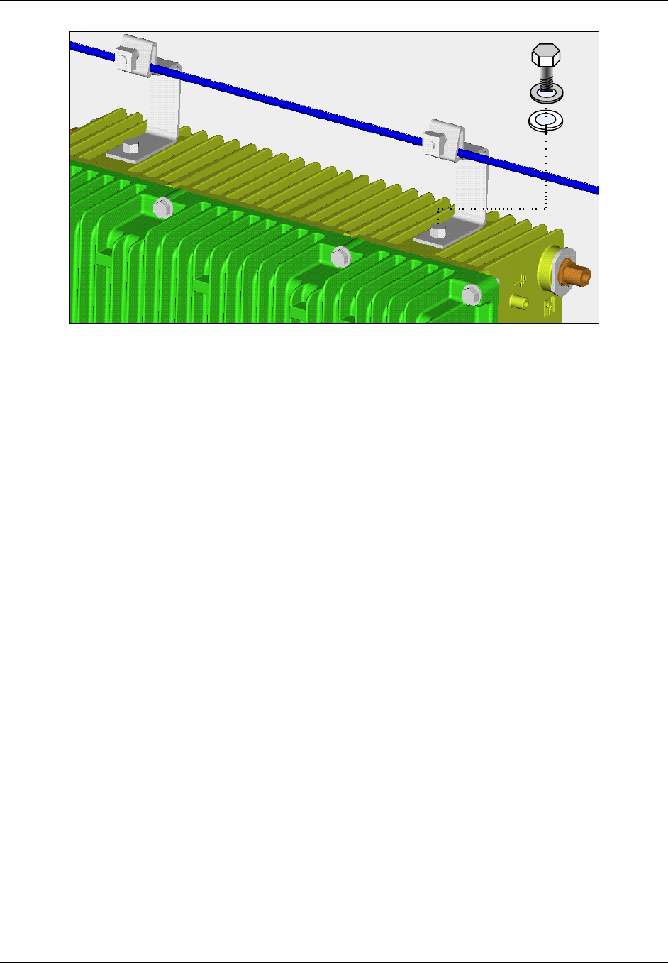
TransCell 1900CB Installation Manual Document No. 1000070A
3-12
TRANSCEPT PROPRIETARY - DATA ON THIS PAGE SUBJECT TO RESTRICTIONS CITED ON COVER AND TITLE PAGE
Figure 3-9. CMI Bracket Installation
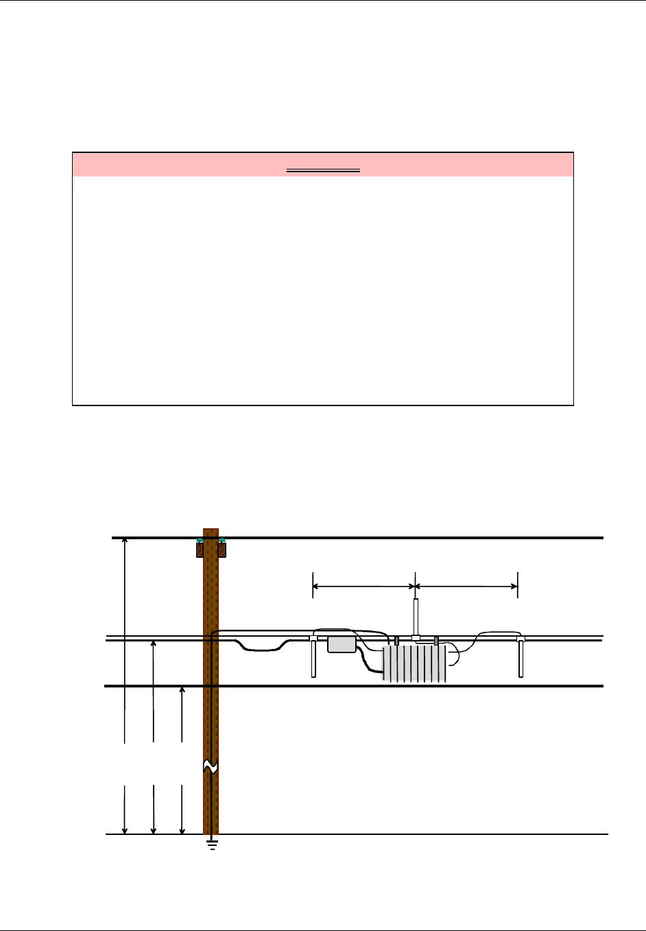
TransCell 1900CB Installation Manual Document No. 1000070A
3-13
TRANSCEPT PROPRIETARY - DATA ON THIS PAGE SUBJECT TO RESTRICTIONS CITED ON COVER AND TITLE PAGE
3.3.5.2 Attaching Antennas to Messenger Strand
This procedure is provided for general guidance when installing the transmit and receive
antennas for the CMI Assembly. The installer should follow the specific installation
procedure provided by the antenna vendor with the antenna equipment.
a. Prior to installing, assemble antenna-mounting bracket provided with antenna.
WARNING
Potentially dangerous High Voltage exists on the AC power cable to the CMI
Assembly that could cause bodily injury or even death. During a line surge or
fault condition, High Voltage also could be present on the antenna
connectors. Use extreme care and required safety precautions while working
on the CMI installation and handling the AC power cable.
To avoid any possibility of overexposure to RF emissions when working near
a CMI, maintain a minimum distance of eight inches from the transmitting
antenna.
NOTE
Ensure that Transmit Antenna element is installed pointing upward and
extending above the messenger strand; ensure that the receive antennas are
pointing downward.
b. Locate and position transmit antenna so that element points upward. Typical
setups are shown in Figure 3-10 for guidance. Attach antenna mounting bracket to
messenger strand.
c. Locate and position two receive antennas so that elements point downward (Figure
3-10).
36 in. min.
Rx
Tx
Rx
Power
Coax
Strand
Telephone
26 ft.
23 ft.
22 ft.
Grounding Wire
36 in. min.
Figure 3-10. Antenna Installation (Option 1)
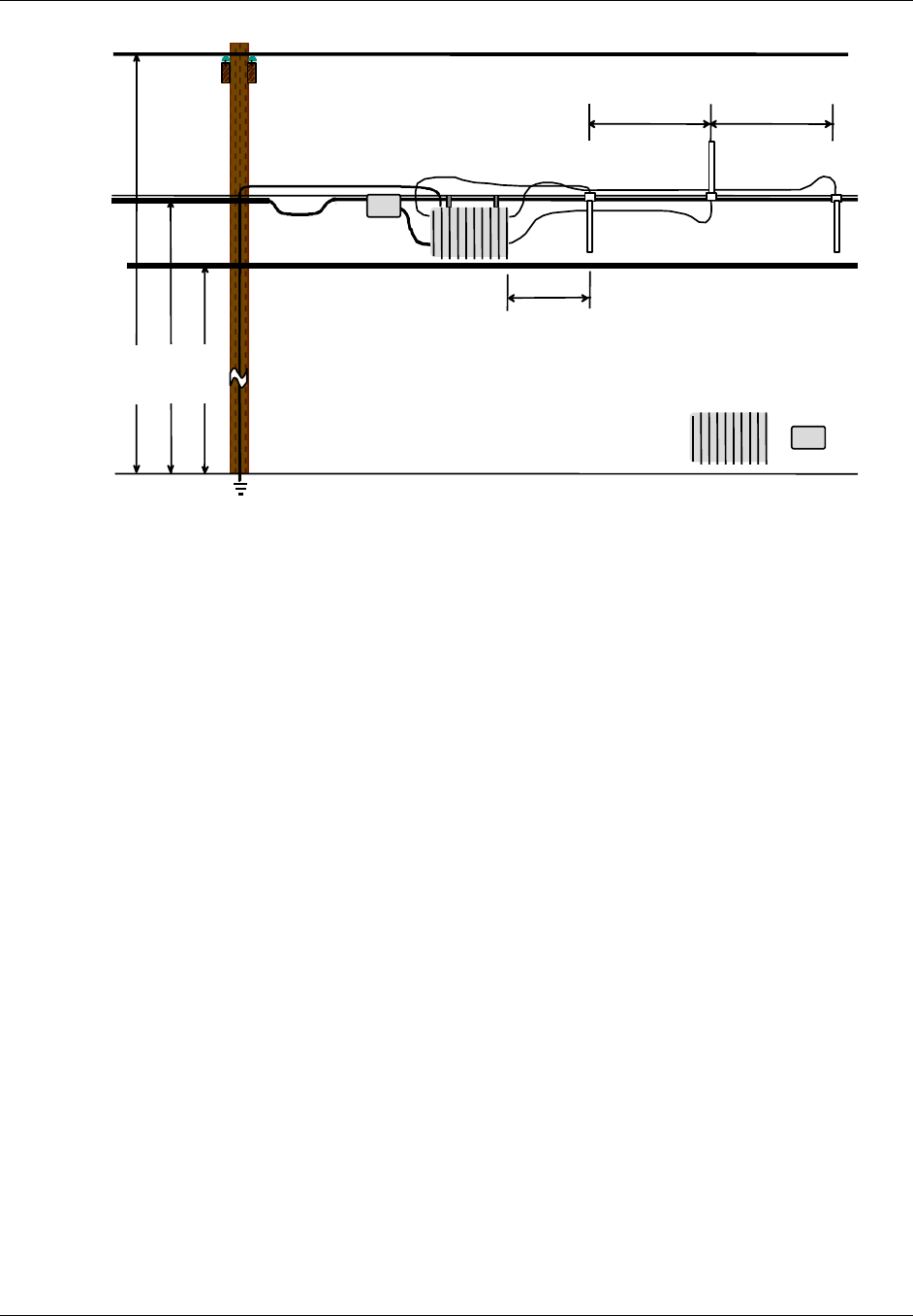
TransCell 1900CB Installation Manual Document No. 1000070A
3-14
TRANSCEPT PROPRIETARY - DATA ON THIS PAGE SUBJECT TO RESTRICTIONS CITED ON COVER AND TITLE PAGE
24 in. min.
36 in. min
.
Rx
Tx
Rx
Power
Coax
Strand
Telephone
26 ft.
23 ft.
22 ft.
Grounding Wire
Directional
Coupler
CMI
36 in. min
.
Figure 3-11. Antenna Installation (Option 2)
3.3.5.3 Installing and Routing Cables
Cable installation and routing includes securing cables to the messenger strand and
interconnecting the various hardware assemblies using (reference 3.3.6).
3.3.5.4 Protective Earth Grounding
The following guidance is provided for the Protective Earth Grounding wire/cable. (Refer to
Figure 3-1 for CMI threaded grounding connection point.) The recommended grounding
hardware is a No. 6 stranded ground wire attached to a No. 6 crimped ground lug with a
No. 10 screw.
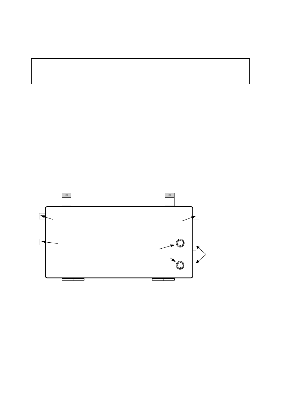
TransCell 1900CB Installation Manual Document No. 1000070A
3-15
TRANSCEPT PROPRIETARY - DATA ON THIS PAGE SUBJECT TO RESTRICTIONS CITED ON COVER AND TITLE PAGE
3.3.5.5 Antenna Cables
This procedure is provided for guidance for routing the antenna cables. This installation
procedure routes the signal cables between the CMI and the three antenna elements. Refer
to Figure 3-12 for CMI connector location.
NOTE
This procedure is intended only as a general guide. The instructions provided
with the Antenna Mounting Kits take precedence over this guide.
a. Temporarily secure each cable with approximately an eight-inch service/drop loop to
messenger strand cable using a tie wrap.
b. Route and connect cables to CMI as follows:
Transmit Antenna element connector to CMI TX antenna connector.
Receive (Primary) Antenna element connector to RX0 connector.
Receive (Diversity) Antenna element connector to RX1 connector.
c. Coil cables to remove excess slack.
d. Secure cables, maintaining an eight-inch service/drop loop to messenger strand
using a tie wrap.
e. Apply waterproofing tape to all connections on CMI Assembly.
RX1 DIVERSITY RECEIVE
ANTENNA CONNECTOR RX0 PRIMARY RECEIVE
ANTENNA CONNECTOR
TX ANTENNA
CONNECTOR CATV PORT
SEIZURE SCREW
ACCESS PORTS
CMI CHASSIS, CURB VIEW
REVTEST
ACCESS PORTS
FWDTEST
Figure 3-12. CMI Assembly Rear View

TransCell 1900CB Installation Manual Document No. 1000070A
3-16
TRANSCEPT PROPRIETARY - DATA ON THIS PAGE SUBJECT TO RESTRICTIONS CITED ON COVER AND TITLE PAGE
3.3.6 Power and CDMA SIGNAL Cables
This procedure is provided for guidance for routing the Power and CDMA signal cables.
a. Ensure that CMI is mechanically configured to accept cables as applicable per
paragraph 3.3.1.
b. Before connecting AC power cable to CMI, verify that source is 110/220VAC,
50/60Hz.
c. Temporarily secure each cable with approximately an eight-inch service/drop loop to
messenger strand using a tie wrap.
d. Route and connect cables to CMI.
e. Coil cables to remove excess slack.
f. Secure cables, maintaining an eight-inch service/drop loop to messenger strand
using a tie wrap.
g. Apply waterproofing seal (customer furnished) to all connections on CMI Assembly.
3.3.7 CMI Power Check
After the CMI is mounted on the cable strand and all cables are installed, do the following:
a. Open CMI per paragraph 3.3.1.
b. For a coaxial installation: if not already done, install the FWD ATTEN pad, REV
ATTEN pad and EQUALIZER pad in power extractor module. Use 0 dB or other
appropriate estimated value (refer to paragraph 3.3.4).
c. Turn on the power supply.
d. Observe that green LED power indicator on Transceiver is illuminated.
e. Close CMI per paragraph 3.3.1.
3.4 MEASUREMENT TEST POINTS
The CMI contains two test ports, one for reverse link and one for the forward link RF
measurements. For the coaxial CMIs, the test point access ports are on the left side of the
CMI when viewed from road. The access ports connect internally to the power extractor, as
shown in Figure 3-13. For the fiber CMIs, the test ports are located on the fiber optic
modules inside the CMI.
NOTE
The FWDTEST and REVTEST measurements can be performed using a
Wavetech Stealth meter or similar device for single tone measurements only.
The Stealth meter is not recommended for measuring wideband signals such
as CDMA.
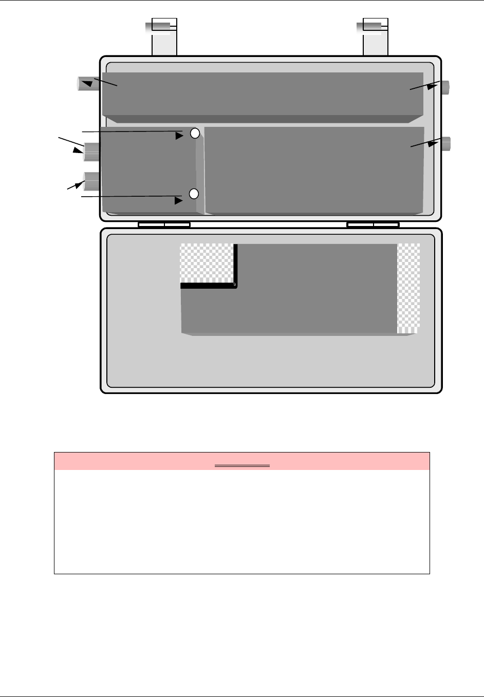
TransCell 1900CB Installation Manual Document No. 1000070A
3-17
TRANSCEPT PROPRIETARY - DATA ON THIS PAGE SUBJECT TO RESTRICTIONS CITED ON COVER AND TITLE PAGE
TRANSCEIVER
TRANSCEIVER
POWER AMPLIFIER
POWER AMPLIFIER
POWER
EXTRACTOR
or
INTERNAL
FIBER OPTIC
UNIT
CHASSIS
RX0 PRIMARY RECEIVE
ANTENNA CONNECTOR
RX1 DIVERSITY RECEIVE
ANTENNA CONNECTOR
TX ANTENNA
CONNECTOR
FWDTEST
REVTEST
COVER
POWER SUPPLY
POWER SUPPLY
1AC IN 9 1
DC
OUT
20
Figure 3-13. CMI Test Point Access and Subassembly Layout
3.5 FORWARD LINK CMI INSTALLATION MEASUREMENTS AND ADJUSTMENTS
WARNING
Potentially dangerous High Voltage exists on the AC power cable to the CMI
Assembly that could cause bodily injury or even death. Use extreme care and
required safety precautions while working on the CMI installation and
handling the AC power cable.
NOTE
The CMI data sheet at the end of this manual may be reproduced and used
for recording the measured levels specified in the following procedures.

TransCell 1900CB Installation Manual Document No. 1000070A
3-18
TRANSCEPT PROPRIETARY - DATA ON THIS PAGE SUBJECT TO RESTRICTIONS CITED ON COVER AND TITLE PAGE
3.5.1 CMI Forward Link Reference and Control Tone Input Level Check
NOTE
The network and assigned HIC at the Hub must be active for the following
level checks. PCS Hub and network technician on-site support is required to
complete the CMI integration procedure.
This procedure checks the forward link reference and control tone signal levels at the CMI
to ensure the levels are within specification.
a. Open CMI per paragraph 3.3.1. Verify that both attenuator pads and equalizer pad,
0 dB or other calculated values, are installed in Power Extractor (Coaxial
installations only).
b. At CMI, access the forward test ports as shown in Figure 3.17.
c. Insert a Long Reach Test Point Adapter through access hole to mate with Power
Extractor test point (-20 dB) for a coaxial CMI or connect to the SMA connectors on
the top of the fiber optic units (-10 dB) for a fiber CMI.
d. At the forward test point, measure the level of HIC forward link Reference Tone at
lower edge of appropriate HIC channel (appropriate forward link channel is user
selectable from HCU). Replace FWD ATTEN pad with a different value as needed or
adjust the trim pots on the fiber optic unit (refer to paragraph 3.3.4) to obtain -75
dBm ± 5 dB for the coaxial CMI and –65 dBm ± 5 dB for the fiber CMI. Record
measured level and pad value.
e. At the forward test point, verify that level of HIC forward link Control Tone. The
appropriate forward link channel is user selectable from HCU and is -75 dBm ± 5
dB for the coaxial CMI and –65 dBm ± 5 dB for the fiber CMI. Record measured
level and pad value.
f. Replace FWDTEST test port plug (coaxial CMI), and close CMI per paragraph 3.3.1.
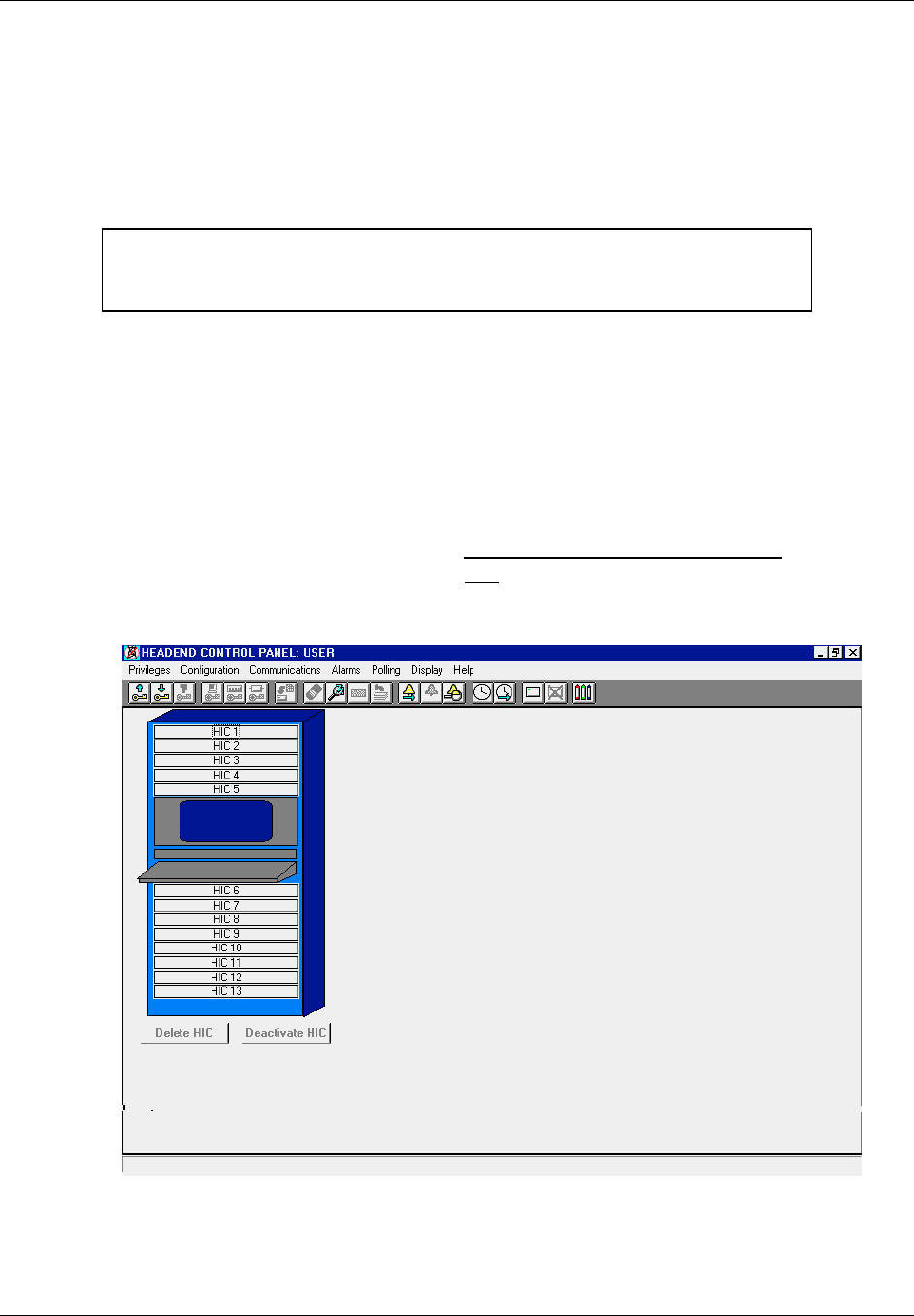
TransCell 1900CB Installation Manual Document No. 1000070A
3-19
TRANSCEPT PROPRIETARY - DATA ON THIS PAGE SUBJECT TO RESTRICTIONS CITED ON COVER AND TITLE PAGE
3.6 REVERSE LINK CMI INSTALLATION MEASUREMENTS AND ADJUSTMENTS
Most reverse link CMI measurements and adjustments are made from the TransCell
1900CB Hub equipment. The only reverse link adjustment made at the CMI is changing
the value of the REV attenuator pad or adjusting the trim pots on the fiber unit.
3.6.1 Activate CMI
NOTE
Although it is not required, it is recommended to have a technician at the
field location of the CMI being activated to complete the integration process.
This procedure, also referred to as CMI acquisition, adds the selected CMI to the database
for monitoring and control by the HCU via the assigned HIC. The procedure also shows
that the HIC and CMI are communicating and that all cable interconnections appear to be
satisfactory.
a. Ensure that Hub enclosure, is turned ON and appropriate HIC is active.
b. At menu bar of HUB CONTROL PANEL dialog (Figure 3-14), select Alarms, then
CMI Manual Override Control.
c. At MANUAL OVERRIDE dialog , click Manual Override Indicator OFF to disable
all Manual Override alarms, then click OK.
d. At HCU CONTROL PANEL dialog, double-click on appropriate HIC icon.
Figure 3-14. Typical HUB CONTROL PANEL Dialog
e. Ensure CMI and HIC are both assigned to the same Forward HIC channel selected
for operation. (Refer to CMI install/initialization paragraphs 3.1 and 3.3.5).

TransCell 1900CB Installation Manual Document No. 1000070A
3-20
TRANSCEPT PROPRIETARY - DATA ON THIS PAGE SUBJECT TO RESTRICTIONS CITED ON COVER AND TITLE PAGE
f. Set HIC CONTROL PANEL dialog (Figure 3-15) controls as follows:
• Click Current Sector (Alpha, Beta, Gamma)
• Ensure that Reverse Frequencies are properly set; click Control button to adjust
if needed.
• Ensure that PCS Frequency is properly set; click Control button to adjust if
needed.
g. At HIC CONTROL PANEL dialog (Figure 3-15), double-click on appropriate CMI
icon (CMI 1 through CMI 100) for sector which selected CMI is to be assigned.
h. Observe that ADD CMI dialog (Figure 3-16) appears.
i. Type data in the following boxes (do not press enter):
• Enter Neuron ID using 12 hexadecimal numbers (required)
• Enter Serial Number (optional reference data)
• Enter Location (optional reference data)
j. Click OK to add new CMI to selected HIC/sector (Alpha/Beta/Gamma).
k. At HIC CONTROL PANEL dialog, confirm that icon of added CMI is green. If
alarms occur and the network/BTS signals are connected and correct, the added
CMI is the suspected failure. Refer to Table 4-2 to confirm probable source of
failure.
NOTE
Table 4-2 lists the alarms recognized by the HCU software and the probable
equipment failure for each alarm. At HUB CONTROL PANEL dialog, Click
Alarms, then Manual Override Control.
l. At CMI MANUAL OVERRIDE dialog, click Manual Override Indicator ON and
select all desired alarms, then click OK.
m. Activate remaining CMIs assigned to selected HIC that are installed in network,
beginning with step g above.
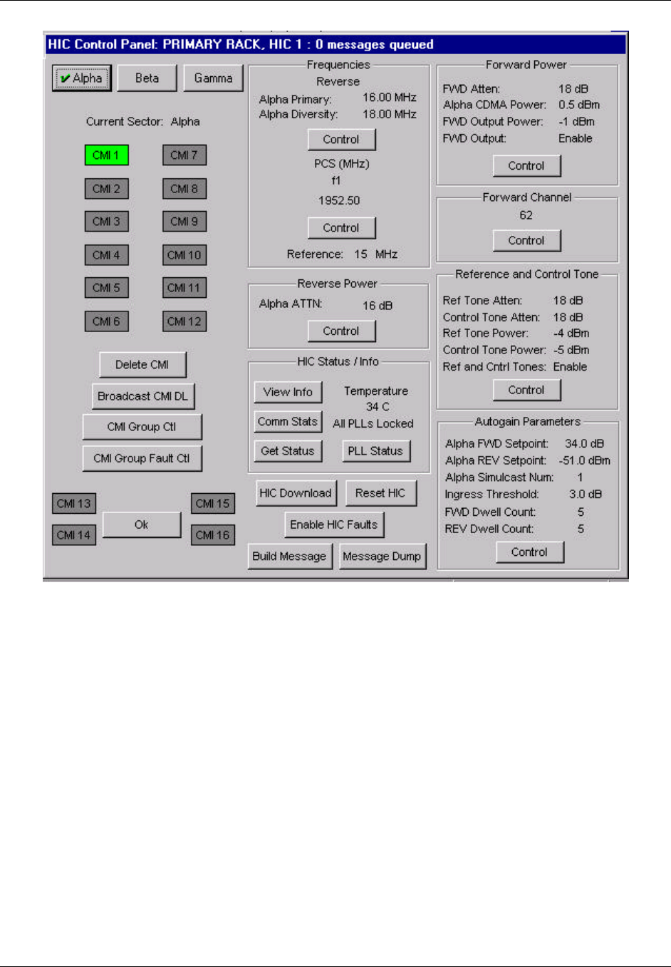
TransCell 1900CB Installation Manual Document No. 1000070A
3-21
TRANSCEPT PROPRIETARY - DATA ON THIS PAGE SUBJECT TO RESTRICTIONS CITED ON COVER AND TITLE PAGE
Figure 3-15. Typical HIC CONTROL PANEL Dialog
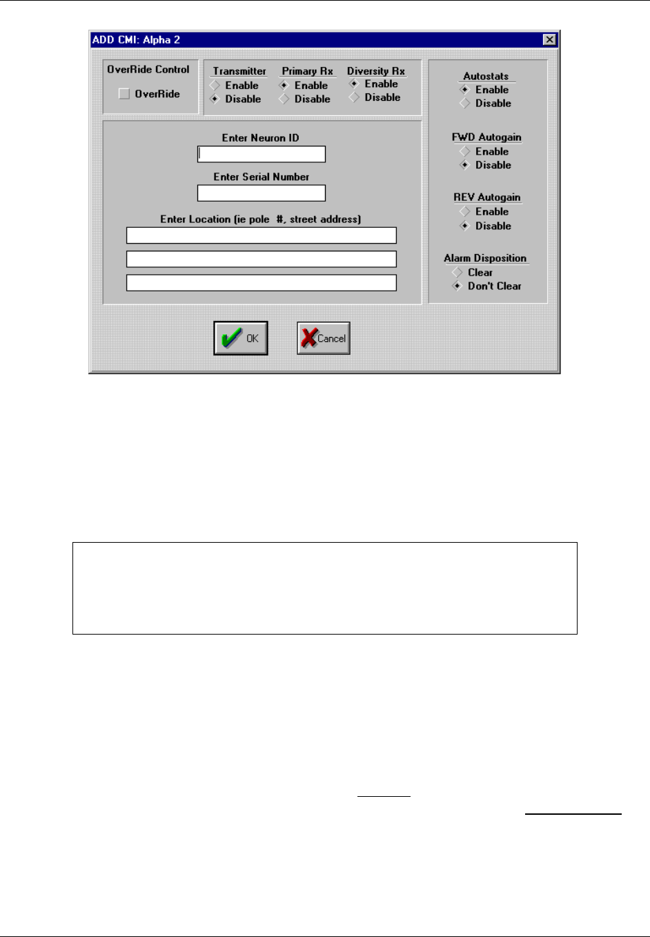
TransCell 1900CB Installation Manual Document No. 1000070A
3-22
TRANSCEPT PROPRIETARY - DATA ON THIS PAGE SUBJECT TO RESTRICTIONS CITED ON COVER AND TITLE PAGE
Figure 3-16. Typical ADD CMI Dialog
3.6.2 Reverse Link Gain Adjustment
This procedure determines the reverse path pad value in the CMI power extractor module
or the amount of adjustment that the trim pot needs to be changed to on the fiber unit, in
order to set up a consistent reverse link gain between the CMI, network loss, and HIC.
Therefore, when all CMIs are set to the operating reverse link setpoint level, they will
operate at roughly the same reverse link output power level.
NOTE
The Reverse Link Gain Adjustment procedure assumes that all fiber nodes;
RFIs (if applicable) on the reverse link of the cable plant have been adjusted
for a consistent gain between fiber node and HIC, in preparation for CMI
deployment.
3.6.2.1 Setting CMI Reverse Link Signal Level Setpoint at HIC
This procedure is used to determine the target reverse link HIC input level from all the
CMIs assigned to a given HIC in a given sector. Subsequently, the reverse AGC setpoint for
each HIC sector will be determined and stored for proper function of reverse autogain.
a. Verify that measured control tone power from each CMI at HIC input is in range of
-54 dBm to -48 dBm, and record value. This level is the reverse autogain setpoint.
b. At HIC CONTROL PANEL dialog, click on Control button to display AUTOGAIN
SETPOINTS dialog. Enter value determined from previous step in REV Setpoint
box for a given sector.
c. Enter number of CMIs that will be operating on the associated sector. The HCU will
automatically determine the Reverse Autogain Setpoint necessary for the reverse
autogain operation.

TransCell 1900CB Installation Manual Document No. 1000070A
3-23
TRANSCEPT PROPRIETARY - DATA ON THIS PAGE SUBJECT TO RESTRICTIONS CITED ON COVER AND TITLE PAGE
3.6.2.2 Measure CMI Reverse Link Control Tone at HIC
a. At HIC CONTROL PANEL dialog, click CMI Group Ctl to display CMI GROUP
CONTROL dialog. At CMI GROUP CONTROL dialog, disable all faults, autostats,
and autogain (FWD and REV) for every CMI attached to HIC.
b. Connect a 50-ohm Type F test connector and cable to a spectrum analyzer (75 Ω
input).
c. Connect a Type F test cable to appropriate sector of HIC REVERSE TEST POINTS
for CMI being measured.
d. Set up spectrum analyzer to reverse link frequency for CMI being adjusted.
e. At HIC CONTROL PANEL dialog, open CMI CONTROL PANEL for CMI being
measured. Set REV Control Tone Attn to 10 dB.
f. Set spectrum analyzer for a ‘Max hold’ measurement.
g. At CMI CONTROL PANEL dialog, click Get Status.
h. Measure and record level of reverse link control tone at HIC REVERSE TEST
POINTS port. This level should be approximately -60 dBm.

TransCell 1900CB Installation Manual Document No. 1000070A
3-24
TRANSCEPT PROPRIETARY - DATA ON THIS PAGE SUBJECT TO RESTRICTIONS CITED ON COVER AND TITLE PAGE
i. At CMI CONTROL PANEL dialog, click Reverse Power Control button to display
CMI REVERSE POWER dialog. At CMI REVERSE POWER dialog, adjust Control
Tone ATTN until reverse control tone is within 2 dB of -60 dBm. Adjust reverse
attenuation as necessary.
j. If Control Tone ATTN setting required is outside the range of 6 to 14 dB, add
attenuation in CMI power extractor by installing a larger value attenuator pad (see
paragraph 3.3.4). After new pad is installed, repeat the steps in paragraph 3.6.2.1 to
verify HIC input power level. Record new pad value.
NOTE
By setting the reverse attenuation of the Power Extractor based on the
Reverse Control ATTN the Reverse Primary ATTN, Reverse Diversity ATTN
and the Reverse Combined ATTN will fall into place.
k. Save this value by clicking Save To EEPROM.
3.6.3 Adjusting Reverse Gain at the HIC
a. Connect a 50-ohm Type F test connector and cable to a spectrum analyzer (75 Ω
input).
b. Connect a Type F test cable to appropriate sector of HIC REVERSE TEST POINTS
for CMI being measured.
c. Set up spectrum analyzer to reverse link frequency for CMI being adjusted.
d. At CMI CONTROL PANEL dialog, click Ping to display the PING CMI dialog.
NOTE
The PING CMI dialog is used to test the reverse continuity for the CMI and
to set the reverse attenuation if necessary.
e. At PING CMI dialog:
1) Select:
? Both Primary and Diversity Pedestal
? In Band
? Test Signal ON
2) Click Send
f. Measure test signal using a peak search and video averaging on spectrum analyzer,
or set marker to CW signal to be measured. Record power level (in dBm).
g. At CMI REVERSE POWER dialog, adjust CMI reverse attenuators to get Ping
Tones at Ping Tone Setpoint window on PING CMI dialog. Note that HIC test point
is 10 dBc below HIC input. Therefore, measured value at HIC test point should be
10 dB below Ping Tone Setpoint.
NOTE
HIC test ports are -10 dBc with respect to the HIC CATV IN ports.
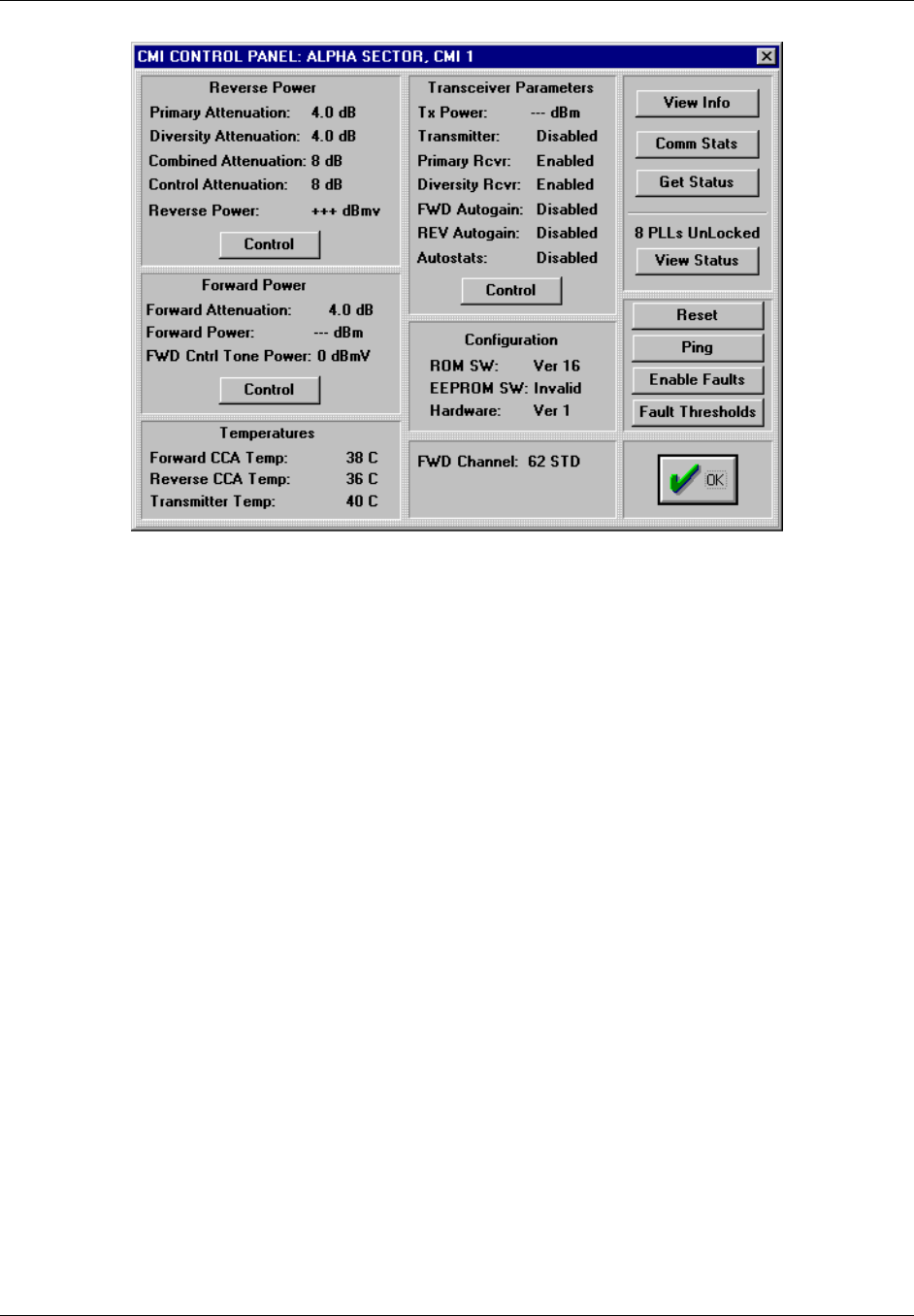
TransCell 1900CB Installation Manual Document No. 1000070A
3-25
TRANSCEPT PROPRIETARY - DATA ON THIS PAGE SUBJECT TO RESTRICTIONS CITED ON COVER AND TITLE PAGE
Figure 3-17. Typical CMI CONTROL PANEL Dialog

TransCell 1900CB Installation Manual Document No. 1000070A
4-1
TRANSCEPT PROPRIETARY - DATA ON THIS PAGE SUBJECT TO RESTRICTIONS CITED ON COVER AND TITLE PAGE
SECTION 4.
BTS INTERFACE AND NETWORK OPTIMIZATION
4 BTS INTERFACE AND NETWORK OPTIMIZATION
4.1 INTRODUCTION
The purpose of this section is to configure a CDMA PCS Base Transceiver Station (BTS) to
operate a group of Cable Microcell Integrators (CMIs) in simulcast. The BTS may or may
not operate a conventional tower configuration in simulcast with the CMI simulcast sector.
The CMI distributed antenna system allows a PCS provider to connect multiple
transceivers to a single sector of a BTS. To allow this, the BTS must be configured to
compensate for the additional delay induced by the transport medium between
transmitters. The BTS has several tools in place to accomplish this, and when configured
properly, the distributed antenna system will be transparent to the network in terms of
timing delay.
If the BTS is to simulcast a conventional tower antenna (macrocell) with a number of
CMIs, the impact to the link budgets of both macrocell and CMIs must be assessed.
4.2 MEASUREMENT/CALCULATION OF CMI DELAYS
Base stations that process PCS calls through TransCell 1900CB equipment require
nonstandard settings due to additional delay in the forward and reverse links. More
specifically, the delay results from the addition of a CMI, a Hub Interface Converter (HIC)
and a coaxial, fiber, or HFC network in the RF path.
For the following four applications, the time delay (that is, coaxial/fiber lengths) between
the forward and reverse links must be determined. The induced delay is either equal or
unequal depending on the coaxial/fiber distances in the forward and reverse paths. The
CMIs involved can be on multiple fiber nodes and/or coax with passive splitters/combiners.
The applicable BTS settings are on a sector basis for each case:
a. Sector dedicated to TransCell 1900CB - Timing equal
b. Sector dedication to TransCell 1900CB - Timing unequal
c. Sector for TransCell 1900CB simulcasting with tower - TransCell 1900CB timing
equal
d. Sector for TransCell 1900CB simulcasting with tower - TransCell 1900CB timing
unequal
4.2.1 Sector Dedicated to TransCell 1900CB - Timing Equal
4.2.1.1 Description
The architecture in Figure 4-1 shows three sectors of a BTS dedicated to TransCell
1900CB. The HFC physical layer for the forward and reverse links is either shared or
parallel and has the same delay times from the BTS to the CMI antenna.
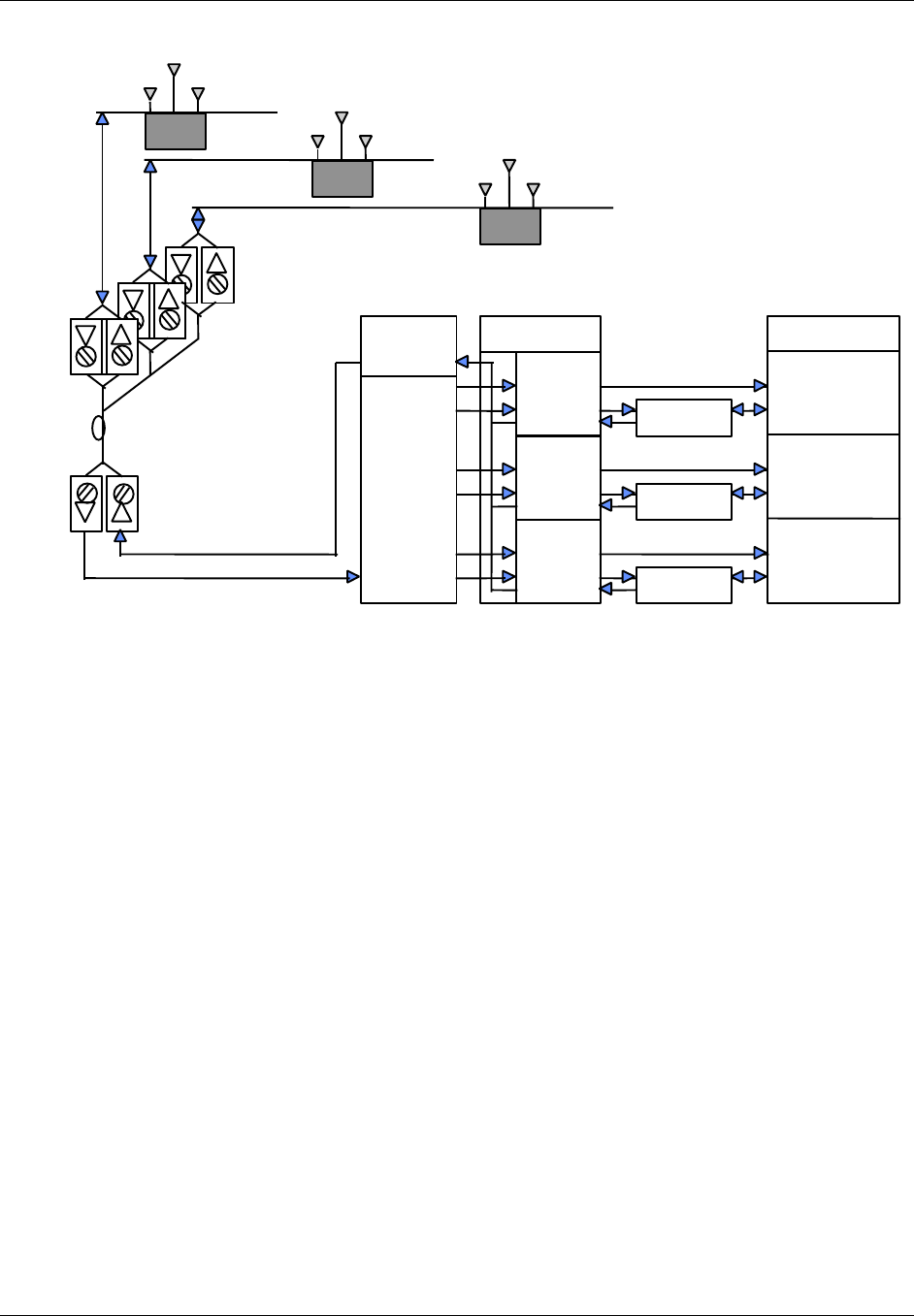
TransCell 1900CB Installation Manual Document No. 1000070A
4-2
TRANSCEPT PROPRIETARY - DATA ON THIS PAGE SUBJECT TO RESTRICTIONS CITED ON COVER AND TITLE PAGE
BTS
γ
DIV Rx
γ
XMIT
& PRI Rx
Forward
Split
Reverse
Combine
and
Split
HIC
α
β
γ
Duplexer
Duplexer
Duplexer
α
XMIT
& PRI Rx
β
XMIT
& PRI Rx
β
DIV Rx
α
DIV Rx
(α,β,
γ)
FIBER
NODES
Fiber Optic
Network
RxdRxp
Tx
COAXIAL
CABLECMI
FIBER
HUB
RxdRxp
Tx
COAXIAL
CABLECMI
(α,β,
γ)
Rxd
Rxp
Tx
COAXIAL
CABLECMI
Figure 4-1. Sector Dedicated to TransCell 1900CB with Equal Timing Links
The delay added by the CMI and the HIC is the same for the forward link as it is for the
reverse link. Since timing is equalized on the network and TransCell 1900CB equipment,
and all PCS communications to the wireless handset are conducted through the CMIs, the
BTS does not have to account for any differential timing on the forward and reverse links
other than that internal to itself.
4.2.1.2 Basic BTS Settings for Dedicated Sector with Equal Timing
For the dedicated sector with equal timing, two TIA/EIA-95-B settings must be taken into
account, time reference and search window size. The BTS sets the search window in which
the mobile unit searches for usable multipath components of the set of appropriate pilot
signals. The following procedures are recommended for determining the setting of these
two parameters.
Regarding the time reference, section 6.1.5.1 of TIA/EIA-95-B states that the personal
station time reference “…shall be within ± 1 µs of the time of occurrence of the earliest
multipath component being used…” This establishes a common reference for system time
when searching for multiple BTS pilot signals.
For a dedicated sector implementation of TransCell 1900CB, the earliest multipath
component in the reverse link would typically appear at the antenna of the CMI that has
the least amount of delay to the base station. To determine which CMI this is, the delay
between each CMI antenna and the BTS input must be determined, either by measuring or
calculating the delay to each CMI antenna. The delay calculation or measurement is made
in a single direction if the timing in the dedicated sector implementation is equal in either
direction. To calculate the delay to a CMI antenna, the following formula is employed:
DTOTAL = DCMI/HIC + DFIBER + DCOAX + DLINE AMP [1]

TransCell 1900CB Installation Manual Document No. 1000070A
4-3
TRANSCEPT PROPRIETARY - DATA ON THIS PAGE SUBJECT TO RESTRICTIONS CITED ON COVER AND TITLE PAGE
where: DCMI/HIC is the group delay in one direction of the CMI and the HIC = 12 µs
DFIBER is the fiber delay at 5 µs/km of fiber (2.04 x 10⁸ m/s). Actual value can be
obtained from fiber/cable specification sheets. It will be slightly different for the
different types of fiber or coaxial cable.
DCOAX is the coaxial delay at 3.8 µs/km (2.74 x 10⁸ m/s). Actual value can be
obtained from fiber/cable specification sheets. It will be slightly different for the
different types of fiber or coaxial cable.
DLINE AMP is the delay added by all the line amps = 10 ns x no. of line amps
(actual value can be obtained from amplifier manufacturer or specification
sheets)
Once all the calculations have been made, the lowest delay value is then used for the time
reference setting on the BTS. This will move 0-system time out to the CMI antenna that is
nearest timewise. The calculated or measured value should be added to the default value
for both “Tx_offset” and Rx_offset”.
NOTE
For the time reference calculation, DAIR is 0 for a handset within 25 feet of the
nearest (timewise) CMI antenna.
The second setting that must be adjusted for TransCell 1900CB is the search window size.
This again is caused by the delay inherent with TransCell 1900CB. The settings affect the
active search window, the neighbor search window, and the remainder search window, if
active. Section 6.6.6.2.1 of TIA/EIA-95-B defines the establishment of search windows and
details the available base station settings and the resultant window sizes. TIA/EIA-95-B
states that: “The search window size for each pilot in the Active Set and the Candidate Set
shall be the number of PN chips specified in Table 6.6.6.2.1-1 with the window centered
around the earliest arriving multipath component of the pilot.”
The window size determines the number of chips off of center that the handset searches
when looking for PN offsets (set of pilot signals). This should be sized according to the
expected delay. The same holds true for the neighbor list and the remainder list. Table 4-1
lists the window size settings in Table 6.6.6.2.1-1 of TIA/EIA-95-B along with the
equivalent delay length.
For the dedicated sector with equal timing, the search window setting is selected from
Table 4-1 after calculating, with Equation [1] above, the delay for both the most delayed
CMI and the least delayed CMI in the sector and calculating the differential. This then is
the range through which the search window must repeatedly pass to pick up all CMIs in
the sector. Equation [2] determines the search window size. The search window is centered
on the CMI antenna that is nearest timewise. This calculation is made with a maximum
over-air propagation delay of 5.1 µs (1.5 km) to the most delayed CMI and a minimum over-
air delay of 0 µs to the least delayed CMI (the CMI whose nearest antenna is 0 system time
set point). Hence the search window size is calculated as shown in Equation [2] in terms of
µs and Table 4-1 determines the setting.
SRCH_WIN_A = (DTOTAL, MAX [DAIR @1.5 km] - DTOTAL, MIN [DAIR @0 km])/2 [2]
Note: DAIR is always zero.

TransCell 1900CB Installation Manual Document No. 1000070A
4-4
TRANSCEPT PROPRIETARY - DATA ON THIS PAGE SUBJECT TO RESTRICTIONS CITED ON COVER AND TITLE PAGE
Table 4-1. Search Window Sizes
Srch_win_Active/Candidate
Srch_win_Neighbor
Srch_win_Remainder
Window Size
(PN chips)
Window Delay
Length (µs)
00 4 3.25
01 6 4.88
02 8 6.50
03 10 8.14
04 14 11.34
05 20 16.28
06 28 22.90
07 40 32.56
08 60 48.84
09 80 65.12
10 100 81.40
11 130 105.82
12 160 130.24
13 226 183.96
14 320 260.48
15 452 367.93
4.2.2 Sector Dedicated to TransCell 1900CB - Timing Unequal
4.2.2.1 Description
This architecture, shown in Figure 4-2, is similar to that shown in Figure 4-1 except that
the forward and reverse paths have different timing. As with section 4.2.1, the BTS sectors
are dedicated to CMIs. Although three sectors are shown, one or two sectors can be
dedicated to TransCell 1900CB with the remainder dedicated to towers. The CMIs can be
on multiple fiber nodes. The HFC physical layer for forward and reverse links is neither
shared nor parallel and has different delay times from BTS to CMI antenna. Since timing
is not equal on the HFC network and all PCS communications to the wireless handset are
conducted through the CMIs, the BTS has to account for the differential timing between
the forward and reverse links on the TransCell 1900CB physical layer. This can be
accomplished through either search windows or differential timing settings. Both are
discussed in the following paragraphs.
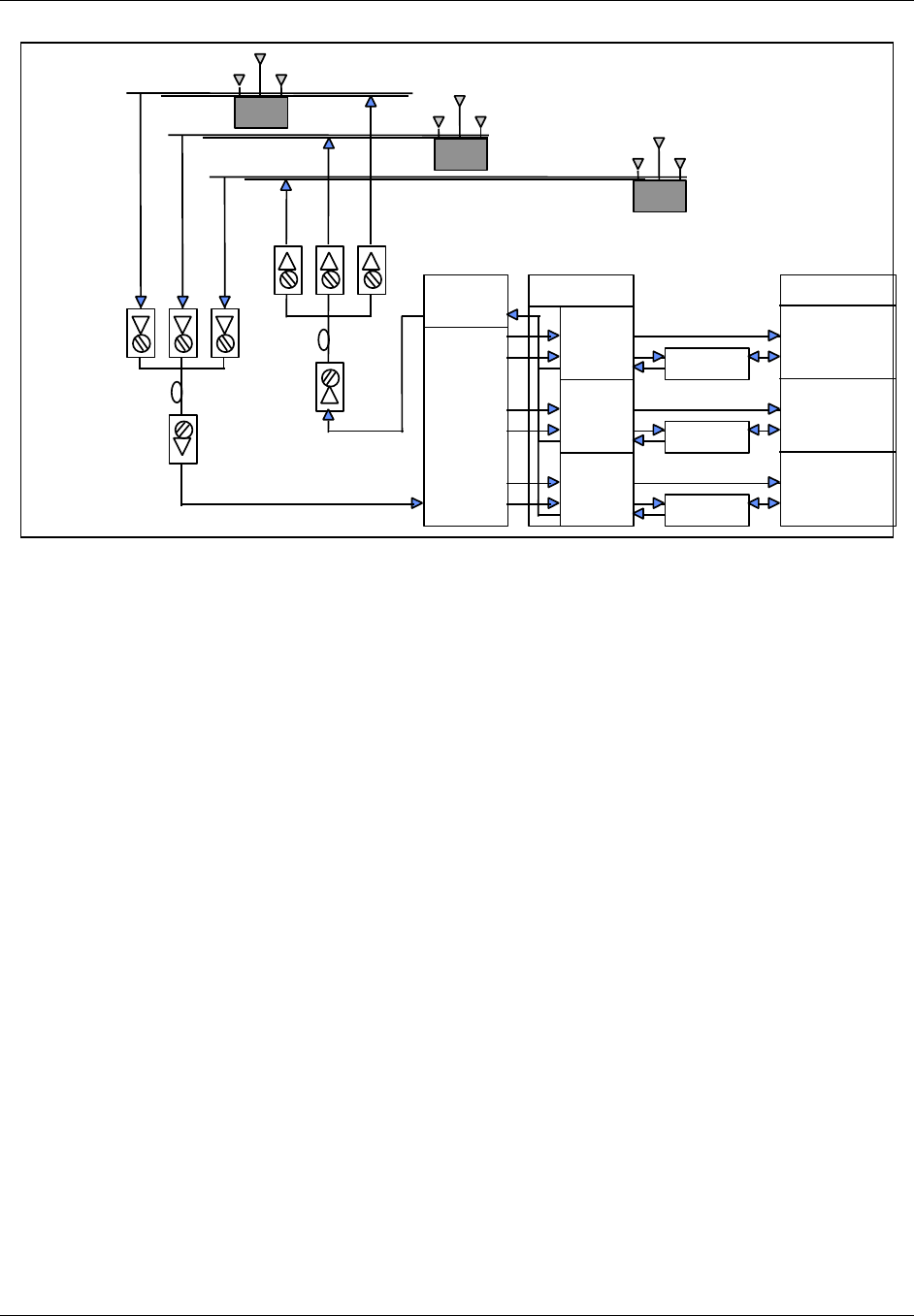
TransCell 1900CB Installation Manual Document No. 1000070A
4-5
TRANSCEPT PROPRIETARY - DATA ON THIS PAGE SUBJECT TO RESTRICTIONS CITED ON COVER AND TITLE PAGE
BTS
γ
DIV Rx
γ
XMIT
& PRI Rx
Forward
Split
Reverse
Combine
and
Split
HIC
α
β
γ
Duplexer
Duplexer
Duplexer
α
XMIT
& PRI Rx
β
XMIT
& PRI Rx
β
DIV Rx
α
DIV Rx
(α,β,
γ)
FIBER
NODES
Fiber Optic
Network
Rxd
Rxp
Tx
COAXIAL CABLE
CMI
FIBER
HUB
Rxd
Rxp
Tx
CMI
(α,β,
γ)
Rxd
Rxp
Tx
CMI
Figure 4-2. Sector Dedicated to TransCell 1900CB with Unequal Timing Links
4.2.2.2 Basic BTS Settings for Dedicated Sector with Unequal Timing
For the dedicated sector with unequal timing, the two basic TIA/EIA-95-B settings already
discussed—time reference and search window size—must be taken into account, and
possibly differential timing as well. The following procedures are recommended for
determining the setting of the two basic parameters.
Time reference is calculated in the same manner as it was in section 4.2.1.2, except that it
is established by determining the delay along both links to each CMI and comparing them.
The delay calculations are made in each direction utilizing Equation [1]. The time reference
is determined by taking the delay that is the smallest and represents the nearest CMI
timewise. The forward path timing delay (Equation [1]) should be added to the default
setting for “Tx_offset”. The reverse path time reference should be added to the default
setting for “Rx_offset”.
The search window size is set in the same manner as it was in section 4.2.1.2. Equation [2]
is used to determine the search window size in µs based on the longest delay path and the
shortest delay path regardless of which link they are on. The shortest delay path is also at
the CMI whose nearest antenna is 0 system time set point. These two values are calculated
with Equation [1]. Table 4-1 is then referred to for the setting once the window size is
determined.
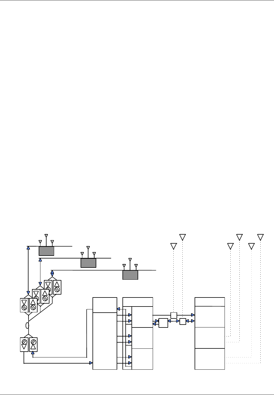
TransCell 1900CB Installation Manual Document No. 1000070A
4-6
TRANSCEPT PROPRIETARY - DATA ON THIS PAGE SUBJECT TO RESTRICTIONS CITED ON COVER AND TITLE PAGE
4.2.3 Simulcasting with a Tower - Timing Equal Within TransCell 1900CB
4.2.3.1 Description
This architecture, shown in Figure 4-3, is similar to that shown in Figure 4-1 except that
the BTS interface is through a coupled port. The RF for the alpha sector is split between
TransCell 1900CB and the tower antenna. This is a tower-CMI simulcast and can be done
on all three sectors, although Figure 4-3 shows it only for the alpha sector. The HFC
physical layer for forward and reverse links is either shared or parallel and has the same
delay times from BTS to CMI antenna.
Timing between links is equalized on the HFC network and TransCell 1900CB equipment
but not with the tower antenna. There will be a significant delay to the CMI because of the
HFC network and TransCell 1900CB group delay. PCS communications to the wireless
handset on the alpha sector can be through either the CMIs or the tower, and they can
hand off to each other. In handing off from the tower to the CMI, the BTS would regard the
CMI signal as a delayed multipath. To discriminate signals from the CMI to the tower, the
BTS would regard the tower signal as an advanced multipath.
4.2.3.2 Basic BTS Settings for Shared Sector with Equal Timing
For the shared sector, two basic TIA/EIA-95-B settings must be taken into account as in
the previous cases, time reference and search window size. The following procedures are
recommended for determining the setting of the two basic parameters.
Time reference is determined at the tower antenna, not the CMI, and assumes that tower
antenna distance from the BTS is less than the distance to the first CMI. This avoids
negative time and meets the TIA/EIA-95-B standard definitions for absolute time. The
delay is calculated from Equation [1] using only the DCOAX term, which defines the delay
over the heliax that runs from the BTS to the tower antenna.
Forward
Split
Reverse
Combine
and
Split
HIC
α
β
γ
(α,β,
γ)
FIBER
NODES
Fiber Optic
Network
Rxd
Rxp
Tx
COAXIAL
CABLECMI
FIBER
HUB
Rxd
Rxp
Tx
COAXIAL
CABLECMI
(α,β,
γ)
Rxd
Rxp
Tx
COAXIAL
CABLECMI
Dpx
BTS
γ
DIV Rx
γ
Tx
& PRI R
x
α
Tx
& PRI R
x
β
T
x
& PRI R
x
β
DIV Rx
α
DIV Rx
Rxd
Tx/Rx
p
Rxd
Tx/Rx
p
β
γ
Rxd
α
30 dB
coupler
Tx/Rx
p
30 dB
coupler
Figure 4-3. Tower Sector Split with TransCell 1900CB - Timing Equal

TransCell 1900CB Installation Manual Document No. 1000070A
4-7
TRANSCEPT PROPRIETARY - DATA ON THIS PAGE SUBJECT TO RESTRICTIONS CITED ON COVER AND TITLE PAGE
The search window size is set in the manner similar to that in paragraph 4.2.1.2 except
that the window is centered around the absolute time at the tower antenna where the time
reference is set. Equation [2] is used to determine the search window size in µs based on
the longest delay path out to the furthest CMI (calculated with Equation [1]) and the
shortest delay path at the time reference antenna (0 second delay). Table 4-1 is then
referred to for the setting once the window size is determined.
It should be noted in this situation that the search window will be opened up more than it
would be for the tower alone. Thus in an established network, where the search windows
have been set prior to the addition of TransCell 1900CB, the search window sizing of
adjacent sectors that can hand off to the CMIs must be reset. The neighbor search windows
for these sectors must be set at the same value as the active search window for the sector
that contains the CMIs since the same delay rationale applies whether it is a handoff
across sectors or within a sector.
4.2.4 Split Sector - Timing Unequal Within TransCell 1900CB
4.2.4.1 Description
This architecture, shown in Figure 4-4, is similar to that shown in Figure 4-2 except that
the BTS interface is through a coupled port. The RF for the sector is split between
TransCell 1900CB and the tower antenna. This is a tower-CMI simulcast and can be done
on all three sectors, although Figure 4-3 shows it only for the alpha sector. The HFC
physical layer for forward and reverse links is neither shared nor parallel and has different
delay times from BTS to different CMI antenna. This is not the case with the tower, which
will have identical timing on the forward and reverse links. Also, as in section 4.2.3, there
will be a significant delay to the CMI as compared to the tower because of the HFC
network and TransCell 1900CB group delay. PCS communications to the wireless handset
on the alpha sector can be through either the CMIs or the tower and they can handoff to
each other. As in section 4.2.3, handing off in either direction is not a problem with the
proper time reference and window settings.
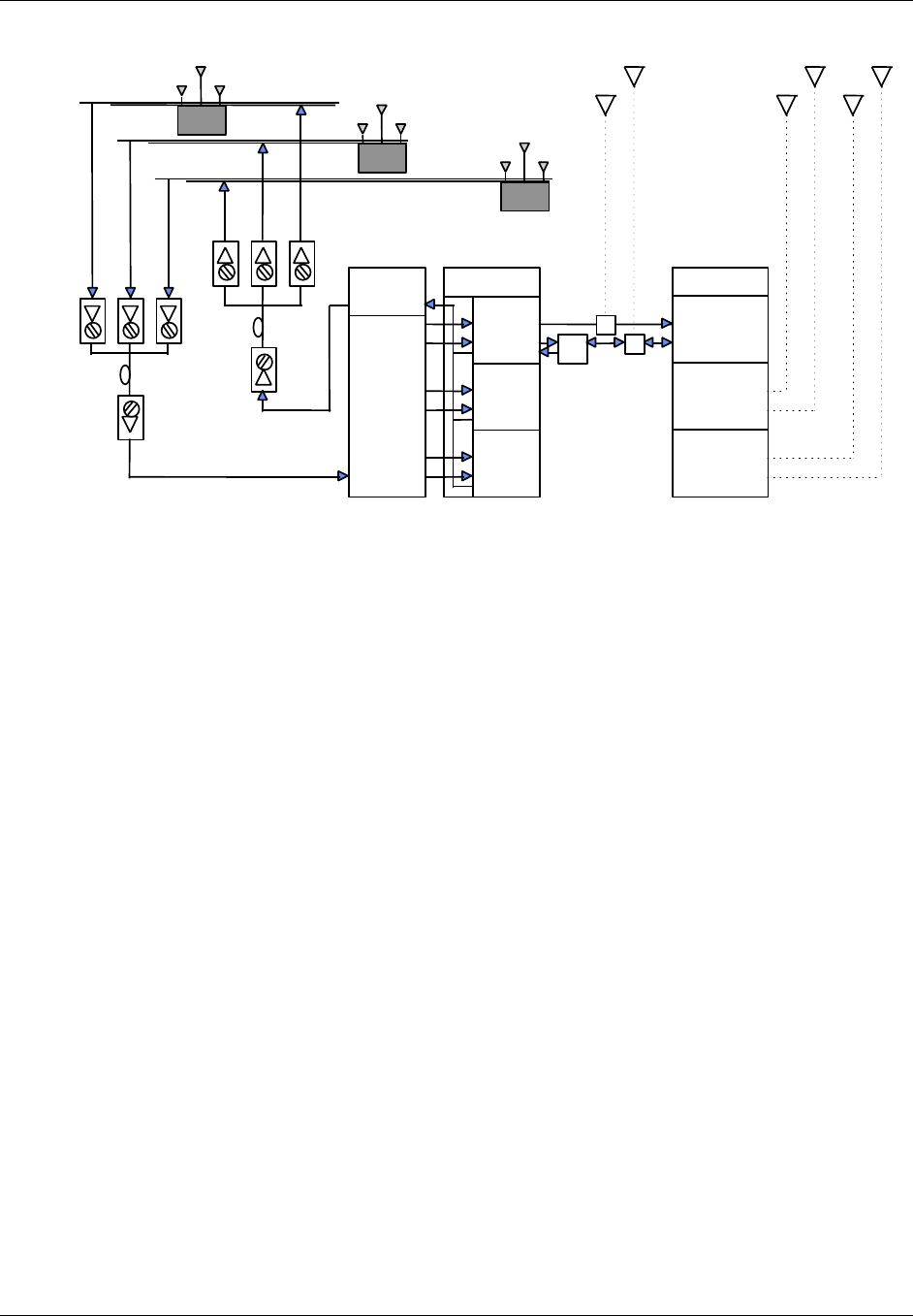
TransCell 1900CB Installation Manual Document No. 1000070A
4-8
TRANSCEPT PROPRIETARY - DATA ON THIS PAGE SUBJECT TO RESTRICTIONS CITED ON COVER AND TITLE PAGE
Forward
Split
Reverse
Combine
and
Split
HIC
α
β
γ
Dpx
(α)
FIBER
NODES
Fiber Optic
Network
Rxd
Rxp
Tx
COAXIAL CABLE
CMI
FIBER
HUB
Rxd
Rxp
Tx
CMI
(α)
Rxd
Rxp
Tx
CMI
BTS
γ
DIV R
x
γ
Tx
& PRI R
x
α
Tx
& PRI R
x
β
Tx
& PRI R
x
β
DIV R
x
α
DIV R
x
Rxd
Tx/Rxp
Rxd
Tx/Rxp
β
γ
Rxd
α
30 dB
coupler
Tx/Rxp
30 dB
coupler
Figure 4-4. Tower Sector Split With TransCell 1900CB - Timing Unequal
4.2.4.2 Basic BTS Settings for Shared Sector with Unequal Timing
For the shared sector, two basic TIA/EIA-95-B settings must be taken into account as in
the previous cases, time reference and search window size. The following procedures are
recommended for determining the setting of the two basic parameters.
As in section 4.2.3, time reference is determined at the tower antenna, not the CMI. The
delay is calculated from Equation [1] using only the DCOAX term, which defines the delay
over the heliax which runs from the base station to the tower antenna.
The search window size is set in the manner similar to that in section 4.2.1.2 except that
the window is centered around the absolute time at the tower antenna where the time
reference is set, and calculations must be made for both the forward and reverse link of all
CMIs. Equation [2] is used to determine the search window size in µs based on the longest
delay path out to the furthest CMI (calculated with Equation [1]) and the shortest delay
path at the time reference antenna (0 second delay). Table 4-1 is then referred to for the
setting once the window size is determined.
As was noted in section 4.2.3.2, the search window will be opened up more than it would be
for the tower alone. In an established network, the search window sizing of adjacent
sectors that can hand off to the CMIs must be reset. The neighbor search windows for these
sectors must be set at the same value as the active search window for the sector that
contains the CMIs since the same delay rationale applies whether it is a handoff across
sectors or within a sector.

TransCell 1900CB Installation Manual Document No. 1000070A
4-9
TRANSCEPT PROPRIETARY - DATA ON THIS PAGE SUBJECT TO RESTRICTIONS CITED ON COVER AND TITLE PAGE
4.3 ASSESSMENT OF BTS SECTORS
Prior to connecting any TransCell 1900CB equipment to the BTS, verify that the applicable
BTS sector has been acceptance tested to the customer’s satisfaction. Also, if the CMIs are
to be simulcast with a macrocell tower antenna, the link budgets of the CMIs and the
macrocell must account for additional degradation in sensitivity and the resulting impact
to the RF footprints of both the tower and the attached CMIs. The BTS coverage tests
should be constructed to adequately address this issue.
All of the RF signal parameters are with respect to a single carrier. If total power is
measured (ie., via a power meter), the user is required to correlate the measurements to a
single carrier (ie., a single carrier is 4.75dB less than a three carrier signal).
4.4 PHYSICAL INTERFACES WITH BTS
The following are recommended procedures for interconnecting the HICs with the BTS and
the Hub.
NOTE
The cables needed for a full enclosure occupy much space and can interfere
with normal equipment servicing by obscuring view and blocking access. As
each HIC is installed, special care should be taken to bundle and route the
cables in a manner that minimizes space use.
In order to complete the following HIC integration procedure, network
technician on-site support is required.
The procedures that follow provide the initial checks and adjustments needed to
integrate an installed (acquired) HIC with the BTS in both Forward and Reverse
directions.
is provided for reference for the Forward link level check, and Figure 4-7 for the Reverse
link level check.
Cross-reference tables for PCS channel number-to-frequency and HIC channel number-to-
frequency are provided in Appendix B and Appendix C, respectively.
a. At HUB CONTROL PANEL: SUPER-USER dialog, double-click on desired installed
HIC (green icon).
b. Observe that HIC CONTROL PANEL dialog appears (Figure 4-9).
c. Verify HIC CONTROL PANEL dialog displays the following desired settings. Click
on associated Control button to change setting, if needed.
• FWD Channel is set as needed by user (channel values)
• Both Reference Tone and Control Tone enabled
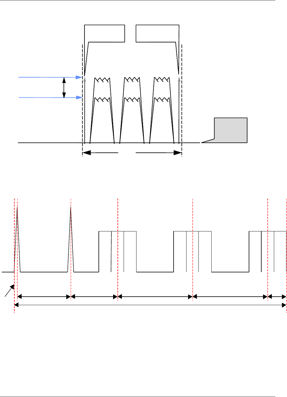
TransCell 1900CB Installation Manual Document No. 1000070A
4-10
TRANSCEPT PROPRIETARY - DATA ON THIS PAGE SUBJECT TO RESTRICTIONS CITED ON COVER AND TITLE PAGE
6 MHz
Pilot Channel
65% CDMA
Traffic Loading
Tuneable within frequency
band of 450 to 750 MHz
Noise
Level
Control Tone
(FSK)
Reference
Tone
7 dB
Figure 4-5. Typical Forward Link Levels; Single Carrier
Figure 4-6. Typical Forward Link Levels; Three Carrier
50KHz
5.8MHz 4.65MHz 5.5MHz 5.5MHz 1.875MHz
α Sector γ Sectorβ Sector
F1
23.375MHz
F2 F3 F1 F2 F3 F1 F2 F3
Reference Control
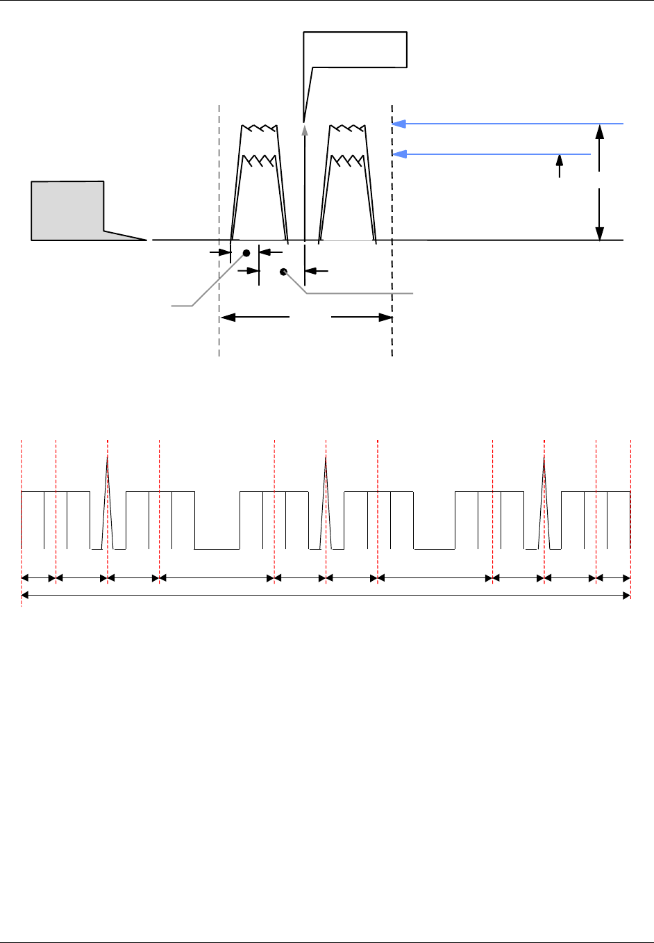
TransCell 1900CB Installation Manual Document No. 1000070A
4-11
TRANSCEPT PROPRIETARY - DATA ON THIS PAGE SUBJECT TO RESTRICTIONS CITED ON COVER AND TITLE PAGE
4.5 dB
Simulcast CMI Noise Floor
65 % CDMA Traffic Loading
4 MHz
Primary
Tuneable within frequency
band of 5 to 52 MHz
20 dB
Noise and
Spurious
Level Diversity
Control Tone
(BPSK)
Fc
885 kHz 1 MHz
Figure 4-7. Typical Reverse Link Levels; Single Carrier
1.875MHz
α Sector
Primary
F1 F2 F3 F1 F2 F3
β Sector
Diversity
F1 F2 F3 F1 F2 F3
γ Sector
Primary
F1 F2 F3 F1 F2 F3
α Sector
Diversity β Sector
Primary γ Sector
Diversity
2.75MHz 2.75MHz 4.5MHz 2.75MHz 2.75MHz 4.5MHz 2.75MHz 2.75MHz 1.875MHz
29.25MHz
Control Control Control
Figure 4-8. Typical Reverse Link Levels; Three Carrier
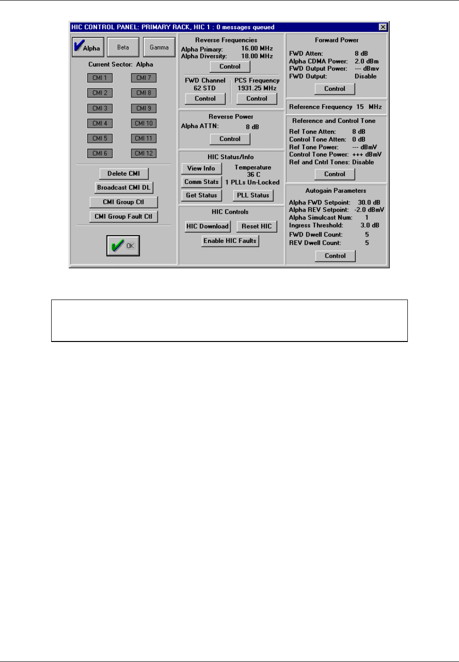
TransCell 1900CB Installation Manual Document No. 1000070A
4-12
TRANSCEPT PROPRIETARY - DATA ON THIS PAGE SUBJECT TO RESTRICTIONS CITED ON COVER AND TITLE PAGE
Figure 4-9. HIC CONTROL PANEL: Dialog
NOTE
The CMI data sheet at the end of this manual may be reproduced and used
for recording the measured levels specified in the following procedures.
4.4.1 Measurement of HIC Reverse Link Output
This procedure assumes that the reverse link from the network has been tested with active
CMIs per paragraphs 2.8.1.
a. For sector to be measured, disconnect RFIA BTS OUT PRI/DIV output cables from
RFIA (if applicable).
b. Disconnect HIC Input cable for sector to be measured (if applicable).
c. Using a 75Ω cable, connect a signal generator to HIC input port of sector to be
measured. Set signal generator as follows with RF output DISABLED:
• Frequency: CMI reverse link Primary (or Diversity) pedestal center frequency
for the sector being measured.
• If measuring RFIA/HIC REV Primary BTS output, set the signal generator to
CMI REV Primary pedestal center frequency; if measuring RFIA/HIC REV
Diversity BTS output, set to the CMI REV Diversity pedestal center frequency.
• RF Output Power Level: -39 dBm Connect spectrum analyzer to HIC BTS OUT
PRI/DIV output terminals using 50 Ω connectors, and set spectrum analyzer as
follows:
• Center Frequency: REV PCS CDMA Channel (Chan. 150 = 1857.5 MHz)
• Scale: 2 dB/div
• Span: 6 MHz
• RBW: 1.25 MHz (or 30 kHz)
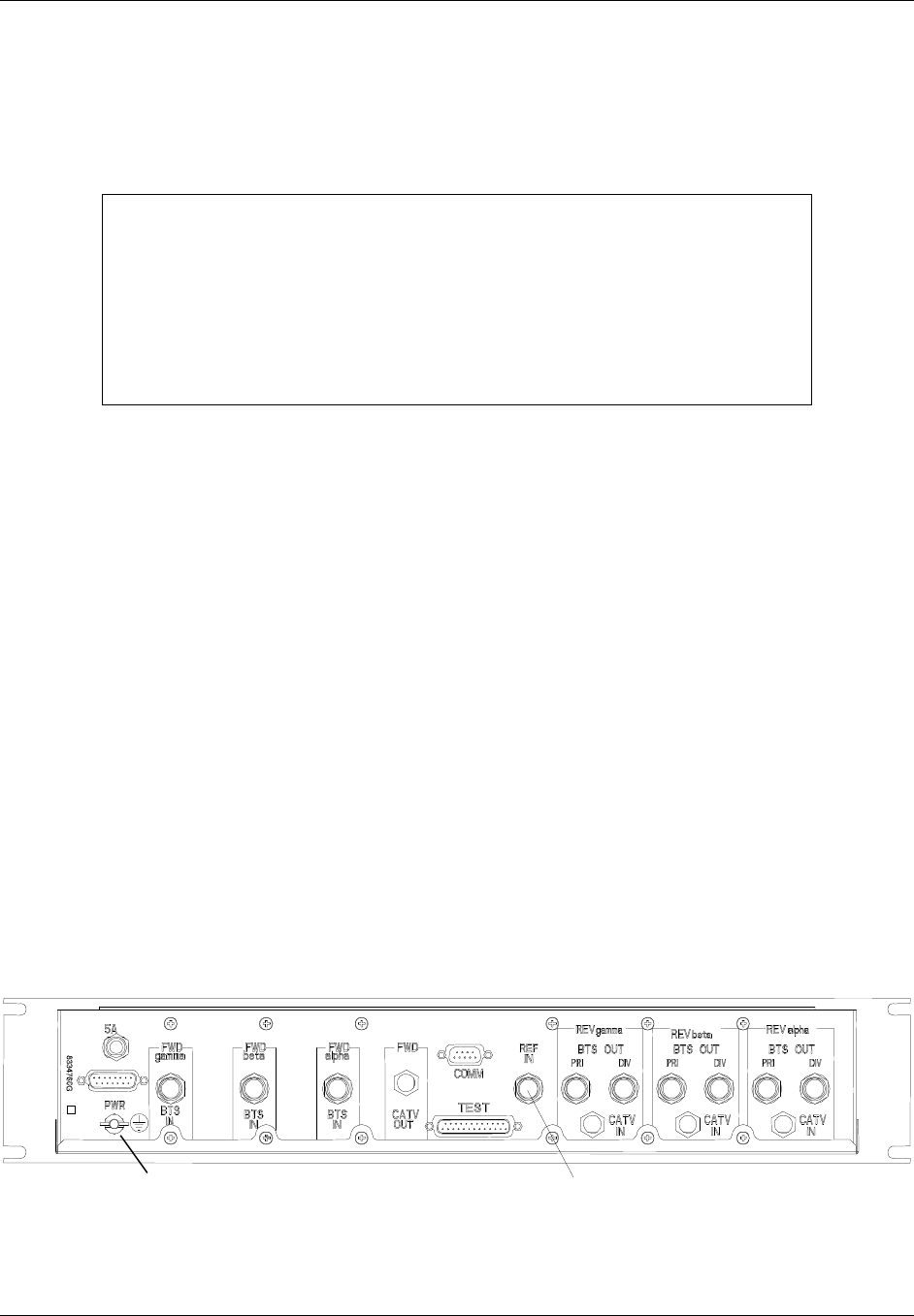
TransCell 1900CB Installation Manual Document No. 1000070A
4-13
TRANSCEPT PROPRIETARY - DATA ON THIS PAGE SUBJECT TO RESTRICTIONS CITED ON COVER AND TITLE PAGE
d. Enable RF output of signal generator to inject CW signal into HIC CATV IN port.
e. Determine if reverse link output level of CW signal is between -50 and -60 dBm.
Adjust reverse link attenuator of HIC until the CW signal is -55 dBm ± 1 dB.
4.4.1.1 HIC CDMA Reverse Link Output to BTS
NOTE
This procedure assumes all connections between the HIC and the network
have been made and the external equipment, RF signals, and
communications are functioning properly.
The Reverse output power of the HIC is -50 to -60 dBm (nominal of -55 dBm)
with –93 dBm injected at CMI receive ports. Depending on cable length and
Reverse BTS input power level specification, external attenuator pads may be
necessary for optimal performance.
The RFIA/HIC provides the CDMA Reverse link input signals to the BTS. Each HIC
provides a pair of reverse link signals for each sector, designated PRI (Primary) and DIV
(Diversity).
a. Connect an RF cable to alpha sector reverse link Primary (Rx - S1D0) input port of
BTS, and route cable to selected RFIA/HIC in the Hub enclosure.
b. Secure cable to appropriate cable troughs to eliminate any strain on cable
connectors.
c. Verify that both reverse RFIA/HIC output levels (primary and diversity) are within
specification in accordance with paragraph 4.4.1.
d. Connect cable to REV alpha BTS OUT PRI port on rear panel of selected RFIA.
(Figure 4-10).
e. Connect an RF cable to alpha sector reverse link Diversity (Rx - S1D1) input port of
BTS, and route cable to selected RFIA/HIC.
f. Connect cable to REV alpha BTS OUT DIV port on rear panel of selected RFIA.
g. Repeat steps a through f for beta sector of RFIA/HIC and BTS, connecting to S2D0
and S2D1 ports on BTS.
h. Repeat steps a through f for gamma sector of RFIA/HIC and BTS, connecting to
S3D0 and S3D1 ports on BTS.
Ground Stud 10 or 15 MHz
Figure 4-10. HIC Rear Panel
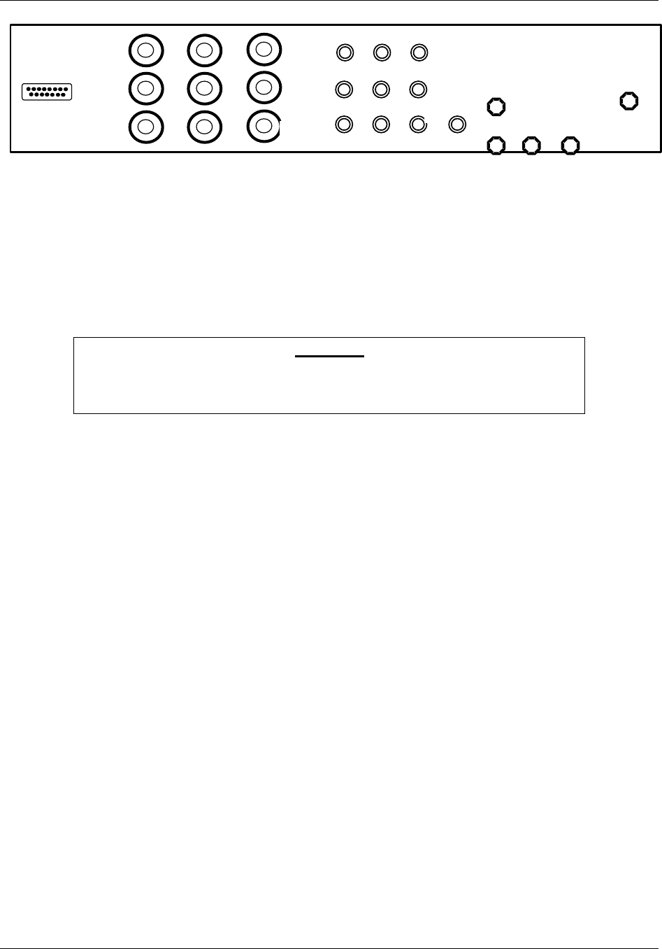
TransCell 1900CB Installation Manual Document No. 1000070A
4-14
TRANSCEPT PROPRIETARY - DATA ON THIS PAGE SUBJECT TO RESTRICTIONS CITED ON COVER AND TITLE PAGE
RxD
RxP
Tx / Rx
RxD
RxP
Tx / Rx
15 MHz
I/O
I/O I/O
I/O
I/O
PWR
Figure 4-11. RFIA Rear Panel
4.4.2 CDMA Forward Link Input from BTS
The BTS provides the CDMA forward link input signal to the installed RFIA/HICs. Each
installed RFIA/HIC is divided into three sectors, designated alpha, beta, and gamma. The
sectors operate independent of each other, communicating over separate cables with three
BTS sectors, also designated alpha, beta, and gamma. The following procedure is used to
measure the HIC forward link CDMA Input Power level after interfacing with the BTS.
CAUTION
Because some BTS units are capable of generating an extremely high forward
link power level, it is important to measure the forward link output of the
BTS prior to connecting it to the HIC input.
a. Connect a Forward link RF cable to alpha sector (S1) forward link CDMA output
port of BTS, and route cable over to vicinity of selected RFIA/HIC in the Hub
enclosure. Do not connect cable at this time.
b. Secure cable to appropriate cable troughs to eliminate any strain on cable
connectors.
c. For sector to be measured, connect HIC forward link CDMA input cable (after
RFIA) from BTS to spectrum analyzer input (50 Ω).
d. Set spectrum analyzer as follows:
• Center Frequency: FWD PCS Channel Frequency
(PCS Ch. 25 = 1931.25 MHz)
• Span: 6 MHz; 1.25 MHz (or 30 kHz RBW)
• Scale: 2 dB/div
• Input Impedance: 50 Ω
• Units: dBm
• Video Averaging: 100 Averages

TransCell 1900CB Installation Manual Document No. 1000070A
4-15
TRANSCEPT PROPRIETARY - DATA ON THIS PAGE SUBJECT TO RESTRICTIONS CITED ON COVER AND TITLE PAGE
e. Measure HIC CDMA input levels from BTS using display line after 100 averages.
Ensure that input levels are within specification:
Single CDMA Carrier, 1.25 MHz RBW
65% Pole Pilot Only
Maximum +5.0 dBm -2.0 dBm
Minimum -2.0 dBm -9.0 dBm
Single CDMA Carrier, 30 kHz RBW
65% Pole Pilot Only
Maximum -12.7 dBm -19.7 dBm
Minimum -19.7 dBm -26.7 dBm
f. Record measured level.
g. After level has been verified, connect Forward link cable between RFIA alpha
sector and FWD alpha BTS IN port on rear panel of selected HIC (Figure 4-10).
h. Repeat steps a through g for beta and gamma sectors to complete one
RFIA/HIC/BTS connection. (The BTS beta sector is S2 and the gamma sector is
S3.)
4.4.3 CDMA Forward Link Output to Coaxial Network
The HIC provides the CDMA Forward link signal to the coaxial network or fiber network
through the HFI. Each HIC provides a single forward link signal (one or three carriers),
the combined output of all three sectors.
a. Connect a forward link RF or Fiber cable from appropriate forward link device in
Hub; route cable to selected HIC or HFI in Hub enclosure.
b. Secure cable to appropriate cable troughs to eliminate any strain on cable
connectors.
c. Connect coaxial cable to FWD CATV OUT port on rear panel of selected HIC for a
coaxial installation (Figure 4-10) or connect the fiber cable to the appropriate HFI
transceiver port.
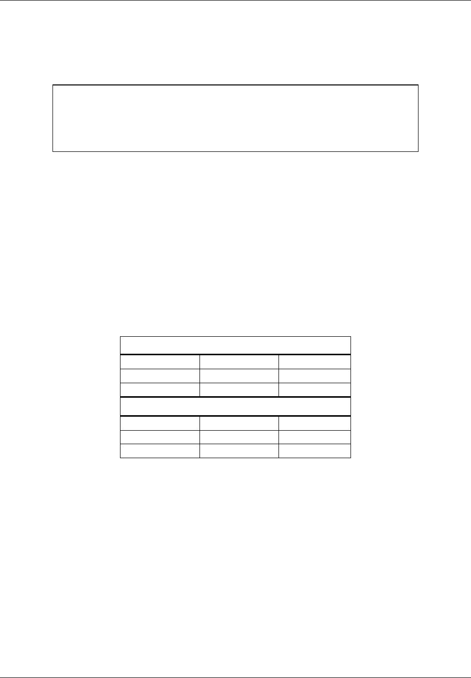
TransCell 1900CB Installation Manual Document No. 1000070A
4-16
TRANSCEPT PROPRIETARY - DATA ON THIS PAGE SUBJECT TO RESTRICTIONS CITED ON COVER AND TITLE PAGE
4.4.3.1 HIC Forward Link CDMA Pilot Level
This procedure verifies that the CDMA Pilot Level at the HIC FWD CATV OUT port is
between -26 and -36 dBm.
NOTE
CDMA levels should be measured in a 1.23-MHz resolution bandwidth.
However, a 30-kHz RBW can be used by adding a 16.1-dB correction factor to
the measured level in order to obtain the actual level.
(16:1 = 10LOG 1.23 MHz/30 kHz)
a. Connect a spectrum analyzer to HIC FORWARD TEST POINT (75 Ω).
b. Set spectrum analyzer as follows:
• Center Frequency: FWD HIC Channel
• Scale: 2 dB/div
• Span: 6 MHz
• RBW: 1.25 MHz (or 30 kHz)
c. Adjust span and/or center frequency so that forward CDMA pedestals for all sectors
can be seen.
d. Measure HIC forward CDMA output at HIC FORWARD TEST POINT with
spectrum analyzer, using display line and 100 averages. Determine if forward link
CDMA power levels are within range:
Single CDMA Carrier, 1.25 MHz RBW
65% Pole Pilot Only
Maximum -19 dBm -26 dBm
Minimum -29 dBm -36 dBm
Single CDMA Carrier, 30 kHz RBW
65% Pole Pilot Only
Maximum -35 dBm -42 dBm
Minimum -45 dBm -52 dBm
e. Adjust attenuation as needed in HIC FORWARD POWER dialog (Figure 4-12) to
attain required power level specification. Record amplitude and attenuator setting.

TransCell 1900CB Installation Manual Document No. 1000070A
4-17
TRANSCEPT PROPRIETARY - DATA ON THIS PAGE SUBJECT TO RESTRICTIONS CITED ON COVER AND TITLE PAGE
Figure 4-12. HIC FORWARD POWER Dialog

TransCell 1900CB Installation Manual Document No. 1000070A
4-18
TRANSCEPT PROPRIETARY - DATA ON THIS PAGE SUBJECT TO RESTRICTIONS CITED ON COVER AND TITLE PAGE
Table 4-2. Recognized Alarm List
Name
Alarm
ID
Action
Indicator Criticality
Alarm
Source
Probable
Equip
BTS Alpha Forward Output Alarm 5Manual Critical HIC BTS
BTS Beta Forward Output Alarm 6Manual Critical HIC BTS
BTS Gamma Forward Output Alarm 7Manual Critical HIC BTS
BTS Alpha Forward Output Warning 8Manual Minor HIC BTS
BTS Beta Forward Output Warning 9Manual Minor HIC BTS
BTS Gamma FWD Output Warning 10 Manual Minor HIC BTS
External Reference Output Alarm 11 Manual Critical HIC Ref Source
HIC Forward Output Alarm 1Manual Critical HIC HIC
HIC Forward Output Warning 2Manual Minor HIC HIC
HIC Forward Communications Alarm 3Manual Minor HIC HIC
HIC Forward Reference Alarm 4Manual Critical HIC HIC
HIC Reverse Output Alarm 12 Manual Critical HIC HIC
HIC Reverse Communications Alarm 13 Manual Minor HIC HIC
HIC Temperature Alarm 14 Manual Minor HIC HIC
HIC Processor Alarm 15 Manual Minor HIC HIC
HIC Not Responding Alarm 16 Manual Critical HCU HCU
HIC Manual Override Alarm * 61 Manual Critical HCU None
CMI Forward Output Alarm 21 Manual Major CMI CMI
CMI Forward Comms Alarm 23 Manual Minor CMI CMI
CMI Forward Reference Alarm 24 Manual Major CMI Network
CMI Reverse Output Alarm 25 Manual Major CMI CMI
CMI Reverse Communications Alarm 26 Manual Minor CMI CMI
CMI Temperature Alarm 27 Manual Minor CMI CMI
CMI Processor Alarm 28 Manual Major CMI CMI
CMI Forward Output Warning 22 Manual Info CMI CMI/
Network
CMI Manual Override Alarm * 62 Manual Major HCU None
CMI Manual Override Warning * 63 Manual Minor HCU None
Network Continuity Warning 42 Manual Minor CMI Network
Network Reverse Continuity Recovered 45 Manual Info CMI Network
Network Forward Continuity Recovered 46 Manual Info CMI Network
Network Continuity Alarm 41 Manual Major HIC Network
Network Forward Continuity Warning 43 Manual Minor HIC Network
Network Reverse Continuity Alarm 44 Manual Major HIC Network
Network Prime Power Alarm 47 Manual Info CMI Network
* The device attribute causing the alarm must be re-enabled before the alarm can be closed.

TransCell 1900CB Installation Manual Document No. 1000070A
4-19
TRANSCEPT PROPRIETARY - DATA ON THIS PAGE SUBJECT TO RESTRICTIONS CITED ON COVER AND TITLE PAGE
4.5 INITIAL SETTING OF BTS PARAMETERS
4.5.1 Initial Conditions
a. The BTS should be installed and connected to the RFIA/ HIC.
b. The CDMA power levels should be set in both directions throughout the TransCell
1900CB system to meet nominal operating conditions.
c. The link budgets associated with the RF footprint of each CMI and macro sector (if
simulcasting with CMIs) should have been evaluated prior to CW testing. The bases
for the link budgets will be verified with the fine-tuning of the BTS parameters
(paragraph 4.6).
4.5.2 Guidelines for Initial Setting of Parameters
The delay to each CMI should be measured/calculated as described in paragraph 4.2. This
measurement/calculation will be used only as a means of establishing an initial phone call
over the TransCell 1900CB system; the actual delay will be measured later.
The forward delay value should be added to the manufacturer’s default forward delay (BTS
hardware delay) in the Tx_offset_fine parameter. The reverse path delay estimate will be
incorporated into the Rx_offset_fine parameter by adding the estimate to the manufac-
turer’s default value. Note that these values may be in either decimal or hexadecimal
depending on the BTS manufacturer. Typically, the values will be entered in units of 1/8
PN chip (approximately 101.75 ns).
The BTS uses a parameter called the access time-out to determine how long to wait for a
given phone to respond to a paging message when originating calls. This parameter may
need to be increased for use with a TransCell 1900CB sector. The parameter to be changed
is called ACC_TMO and defines the access time-out by the equation:
TA = (2 + ACC_TMO) * 80 ms
Typically, an increase of 2 or 3 units will be sufficient. A larger increase can be used
initially, then stepped down later during system optimization.
At this point it should be possible to place a call at the nearest CMI location using the CMI
transport system in both directions. A mobile diagnostic monitor can be used to verify that
the forward link signal is using the CMI path, rather than an “over-air” path from a
distant tower. In the reverse direction, the CMI receivers can be disabled to verify which
CMI path is being utilized.
Once it is confirmed that the call is using the CMI transport path in both directions, a call
trace should be initiated on the given test phone and used to monitor a phone call for
several seconds. The switch log of the call trace will record round trip delay from the
channel cards in the BTS through the mobile unit. This value will be used to refine the
earlier delay estimates.
The round-trip delay divided by 2 will yield a preliminary one-way delay. (Note: It is very
important that the physical transport path be identical in both directions. If this is not the
case, then a BTS correction factor is needed to compensate for BTS propagation delay
differences in the two directions. (i.e., Tx_Delay offset, Rx_Delay offset).

TransCell 1900CB Installation Manual Document No. 1000070A
4-20
TRANSCEPT PROPRIETARY - DATA ON THIS PAGE SUBJECT TO RESTRICTIONS CITED ON COVER AND TITLE PAGE
4.6 OPTIMIZING BTS PARAMETER SETTINGS
a. Activate all CMIs and towers to be used in the network.
b. Conduct extensive drive test to verify call origination and handoff performance.
c. Adjust timing parameters as necessary to improve call-processing performance.

TransCell 1900CB Installation Manual Document No. 1000070A
A-3
TRANSCEPT PROPRIETARY - DATA ON THIS PAGE SUBJECT TO RESTRICTIONS CITED ON COVER AND TITLE PAGE
Appendix A
Radio Frequency Interface Assembly (RFIA)
Configuration Procedure

TransCell 1900CB Installation Manual Document No. 1000070A
A-3
TRANSCEPT PROPRIETARY - DATA ON THIS PAGE SUBJECT TO RESTRICTIONS CITED ON COVER AND TITLE PAGE
Radio Frequency Interface Assembly (RFIA) Configuration Procedure
A-1 TOOLS REQUIRED
♦ DVM
♦ Common hand tools
A-2 SUPPLIES REQUIRED
♦ Cable ties (furnished)
♦ Miscellaneous internal interconnect cables (furnished)
♦ Cabling for external connections to BTS and cable plant (supplied by customer)
A-3 EQUIPMENT DESCRIPTION
The RF Interface Assembly (RFIA) provides an interface between the HIC, BTS, HFI, and
Coaxial Network. It also generates a stable 15-MHz reference signal to the HICs installed
in the indoor enclosure and the outdoor enclosure.
The RF Interface Plate Assembly (see Figure C-1) serves as a transition point within the
Hub equipment enclosure to convert the larger and more rigid cabling from the BTS and
coaxial network to smaller and more flexible cabling to the HIC. One RFIA is required for
each HIC installed. This configuration is mounted in the rear of the enclosure directly
above the associated HIC and occupies space the size of one HIC.
This panel provides the interface between the HIC (“TNC” connectors), the BTS (“N”
connectors) and the coaxial network or the HFI (“F” connectors). There are nine type N
connectors that interface the signals for the three sectors from the BTS to the HIC and four
type F connectors that interface the reverse IF signals and the forward IF signal for all
three sectors to the HIC. A 15 MHz oscillator on the assembly provides a reference
frequency for the HIC.
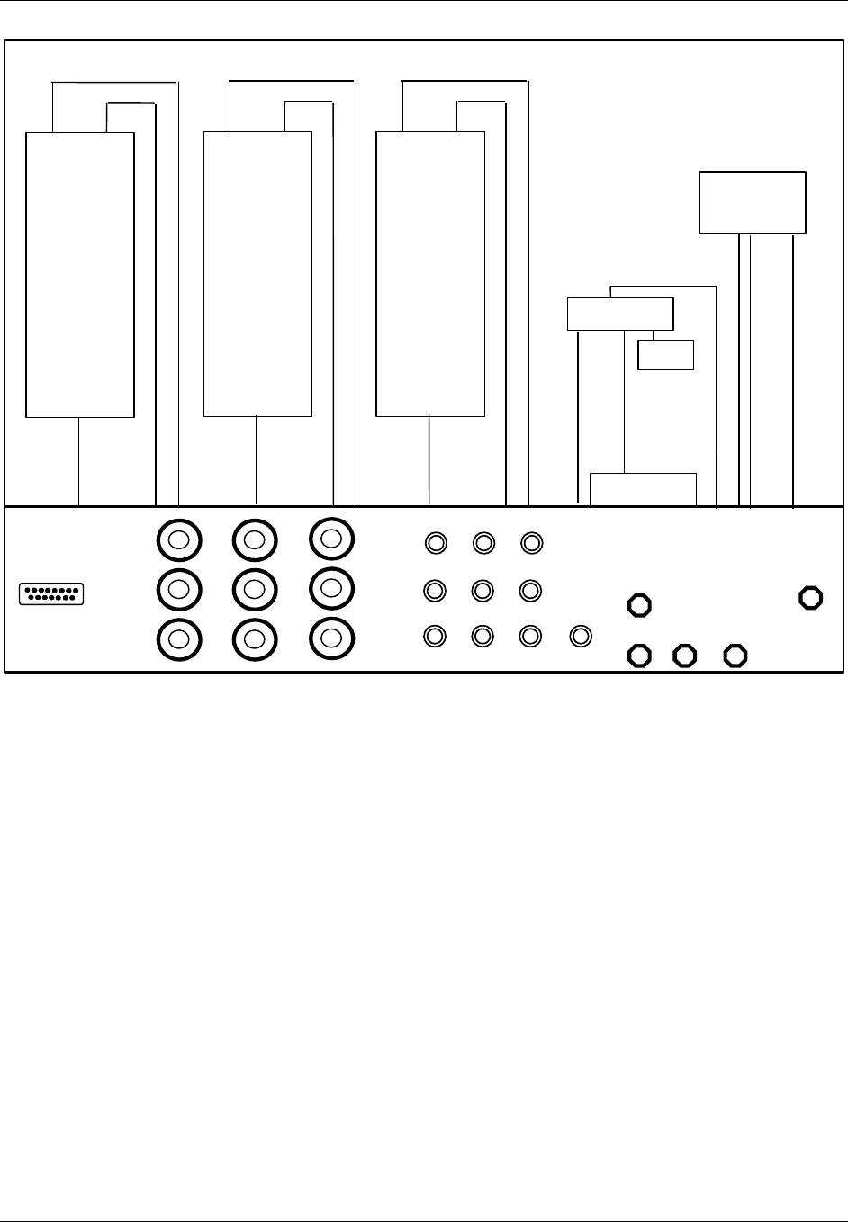
TransCell 1900CB Installation Manual Document No. 1000070A
A-3
TRANSCEPT PROPRIETARY - DATA ON THIS PAGE SUBJECT TO RESTRICTIONS CITED ON COVER AND TITLE PAGE
RxD
RxP
Tx / Rx
RxD
RxP
Tx / Rx
15 MHz
I/O
I/O
I/O
I/O
I/O
PWR
TX RX
Duplexer
ANT
TX RX
Duplexer
ANT
TX RX
Duplexer
ANT
3-Way Splitter
3-Way Splitter
Oscillator
Term
Figure C-1. RF Interface Plate Assembly
The RFIA configurations provide duplexing of the RF signals between the HIC, the BTS
and the coaxial network or HFI. When necessary, amplifiers may be inserted to increase
the power levels of the signals between the HIC and BTS.
A duplexer is used to permit coupling of transmit and receive signals through a single port.
This device is used primarily for those installations that require the interfacing a single
BTS sector to a single HIC, or two or three sectors of a BTS to a single HIC.
One RFIA is required for each HIC installed. Each RFIA requires +24 VDC for operation.

TransCell 1900CB Installation Manual Document No. 1000070A
B-1
TRANSCEPT PROPRIETARY - DATA ON THIS PAGE SUBJECT TO RESTRICTIONS CITED ON COVER AND TITLE PAGE
Appendix B
PCS Channel Number-To-Frequency
Cross-reference

TransCell 1900CB Installation Manual Document No. 1000070A
B-2
TRANSCEPT PROPRIETARY - DATA ON THIS PAGE SUBJECT TO RESTRICTIONS CITED ON COVER AND TITLE PAGE
PCS Channel Number-to-Frequency Cross Reference
PCS Ch. No. PCS Tx Freq.
(MHz)
PCS Rx Freq.
(MHz)
PCS Ch. No. PCS Tx Freq.
(MHz)
PCS Rx Freq.
(MHz)
PCS Ch. No. PCS Tx Freq.
(MHz)
PCS Rx Freq.
(MHz)
A Band: 0 - 299 * 50 1932.50 1852.50 101 1935.05 1855.05
01930.00 1850.00 51 1932.55 1852.55 102 1935.10 1855.10
11930.05 1850.05 52 1932.60 1852.60 103 1935.15 1855.15
21930.10 1850.10 53 1932.65 1852.65 104 1935.20 1855.20
31930.15 1850.15 54 1932.70 1852.70 105 1935.25 1855.25
41930.20 1850.20 55 1932.75 1852.75 106 1935.30 1855.30
51930.25 1850.25 56 1932.80 1852.80 107 1935.35 1855.35
61930.30 1850.30 57 1932.85 1852.85 108 1935.40 1855.40
71930.35 1850.35 58 1932.90 1852.90 109 1935.45 1855.45
81930.40 1850.40 59 1932.95 1852.95 110 1935.50 1855.50
91930.45 1850.45 60 1933.00 1853.00 111 1935.55 1855.55
10 1930.50 1850.50 61 1933.05 1853.05 112 1935.60 1855.60
11 1930.55 1850.55 62 1933.10 1853.10 113 1935.65 1855.65
12 1930.60 1850.60 63 1933.15 1853.15 114 1935.70 1855.70
13 1930.65 1850.65 64 1933.20 1853.20 115 1935.75 1855.75
14 1930.70 1850.70 65 1933.25 1853.25 116 1935.80 1855.80
15 1930.75 1850.75 66 1933.30 1853.30 117 1935.85 1855.85
16 1930.80 1850.80 67 1933.35 1853.35 118 1935.90 1855.90
17 1930.85 1850.85 68 1933.40 1853.40 119 1935.95 1855.95
18 1930.90 1850.90 69 1933.45 1853.45 120 1936.00 1856.00
19 1930.95 1850.95 70 1933.50 1853.50 121 1936.05 1856.05
20 1931.00 1851.00 71 1933.55 1853.55 122 1936.10 1856.10
21 1931.05 1851.05 72 1933.60 1853.60 123 1936.15 1856.15
22 1931.10 1851.10 73 1933.65 1853.65 124 1936.20 1856.20
23 1931.15 1851.15 74 1933.70 1853.70 125 1936.25 1856.25
24 1931.20 1851.20 75 1933.75 1853.75 126 1936.30 1856.30
25 1931.25 1851.25 76 1933.80 1853.80 127 1936.35 1856.35
26 1931.30 1851.30 77 1933.85 1853.85 128 1936.40 1856.40
27 1931.35 1851.35 78 1933.90 1853.90 129 1936.45 1856.45
28 1931.40 1851.40 79 1933.95 1853.95 130 1936.50 1856.50
29 1931.45 1851.45 80 1934.00 1854.00 131 1936.55 1856.55
30 1931.50 1851.50 81 1934.05 1854.05 132 1936.60 1856.60
31 1931.55 1851.55 82 1934.10 1854.10 133 1936.65 1856.65
32 1931.60 1851.60 83 1934.15 1854.15 134 1936.70 1856.70
33 1931.65 1851.65 84 1934.20 1854.20 135 1936.75 1856.75
34 1931.70 1851.70 85 1934.25 1854.25 136 1936.80 1856.80
35 1931.75 1851.75 86 1934.30 1854.30 137 1936.85 1856.85
36 1931.80 1851.80 87 1934.35 1854.35 138 1936.90 1856.90
37 1931.85 1851.85 88 1934.40 1854.40 139 1936.95 1856.95
38 1931.90 1851.90 89 1934.45 1854.45 140 1937.00 1857.00
39 1931.95 1851.95 90 1934.50 1854.50 141 1937.05 1857.05
40 1932.00 1852.00 91 1934.55 1854.55 142 1937.10 1857.10
41 1932.05 1852.05 92 1934.60 1854.60 143 1937.15 1857.15
42 1932.10 1852.10 93 1934.65 1854.65 144 1937.20 1857.20
43 1932.15 1852.15 94 1934.70 1854.70 145 1937.25 1857.25
44 1932.20 1852.20 95 1934.75 1854.75 146 1937.30 1857.30
45 1932.25 1852.25 96 1934.80 1854.80 147 1937.35 1857.35
46 1932.30 1852.30 97 1934.85 1854.85 148 1937.40 1857.40
47 1932.35 1852.35 98 1934.90 1854.90 149 1937.45 1857.45
48 1932.40 1852.40 99 1934.95 1854.95 150 1937.50 1857.50
49 1932.45 1852.45 100 1935.00 1855.00 * Ch. 0 to 24 Not Valid

TransCell 1900CB Installation Manual Document No. 1000070A
B-3
TRANSCEPT PROPRIETARY - DATA ON THIS PAGE SUBJECT TO RESTRICTIONS CITED ON COVER AND TITLE PAGE
PCS Channel Number-to-Frequency Cross Reference (continued)
PCS Ch. No. PCS Tx Freq.
(MHz)
PCS Rx Freq.
(MHz)
PCS Ch. No. PCS Tx Freq.
(MHz)
PCS Rx Freq.
(MHz)
PCS Ch. No. PCS Tx Freq.
(MHz)
PCS Rx Freq.
(MHz)
151 1937.55 1857.55 201 1940.05 1860.05 251 1942.55 1862.55
152 1937.60 1857.60 202 1940.10 1860.10 252 1942.60 1862.60
153 1937.65 1857.65 203 1940.15 1860.15 253 1942.65 1862.65
154 1937.70 1857.70 204 1940.20 1860.20 254 1942.70 1862.70
155 1937.75 1857.75 205 1940.25 1860.25 255 1942.75 1862.75
156 1937.80 1857.80 206 1940.30 1860.30 256 1942.80 1862.80
157 1937.85 1857.85 207 1940.35 1860.35 257 1942.85 1862.85
158 1937.90 1857.90 208 1940.40 1860.40 258 1942.90 1862.90
159 1937.95 1857.95 209 1940.45 1860.45 259 1942.95 1862.95
160 1938.00 1858.00 210 1940.50 1860.50 260 1943.00 1863.00
161 1938.05 1858.05 211 1940.55 1860.55 261 1943.05 1863.05
162 1938.10 1858.10 212 1940.60 1860.60 262 1943.10 1863.10
163 1938.15 1858.15 213 1940.65 1860.65 263 1943.15 1863.15
164 1938.20 1858.20 214 1940.70 1860.70 264 1943.20 1863.20
165 1938.25 1858.25 215 1940.75 1860.75 265 1943.25 1863.25
166 1938.30 1858.30 216 1940.80 1860.80 266 1943.30 1863.30
167 1938.35 1858.35 217 1940.85 1860.85 267 1943.35 1863.35
168 1938.40 1858.40 218 1940.90 1860.90 268 1943.40 1863.40
169 1938.45 1858.45 219 1940.95 1860.95 269 1943.45 1863.45
170 1938.50 1858.50 220 1941.00 1861.00 270 1943.50 1863.50
171 1938.55 1858.55 221 1941.05 1861.05 271 1943.55 1863.55
172 1938.60 1858.60 222 1941.10 1861.10 272 1943.60 1863.60
173 1938.65 1858.65 223 1941.15 1861.15 273 1943.65 1863.65
174 1938.70 1858.70 224 1941.20 1861.20 274 1943.70 1863.70
175 1938.75 1858.75 225 1941.25 1861.25 275 1943.75 1863.75
176 1938.80 1858.80 226 1941.30 1861.30 276 1943.80 1863.80
177 1938.85 1858.85 227 1941.35 1861.35 277 1943.85 1863.85
178 1938.90 1858.90 228 1941.40 1861.40 278 1943.90 1863.90
179 1938.95 1858.95 229 1941.45 1861.45 279 1943.95 1863.95
180 1939.00 1859.00 230 1941.50 1861.50 280 1944.00 1864.00
181 1939.05 1859.05 231 1941.55 1861.55 281 1944.05 1864.05
182 1939.10 1859.10 232 1941.60 1861.60 282 1944.10 1864.10
183 1939.15 1859.15 233 1941.65 1861.65 283 1944.15 1864.15
184 1939.20 1859.20 234 1941.70 1861.70 284 1944.20 1864.20
185 1939.25 1859.25 235 1941.75 1861.75 285 1944.25 1864.25
186 1939.30 1859.30 236 1941.80 1861.80 286 1944.30 1864.30
187 1939.35 1859.35 237 1941.85 1861.85 287 1944.35 1864.35
188 1939.40 1859.40 238 1941.90 1861.90 288 1944.40 1864.40
189 1939.45 1859.45 239 1941.95 1861.95 289 1944.45 1864.45
190 1939.50 1859.50 240 1942.00 1862.00 290 1944.50 1864.50
191 1939.55 1859.55 241 1942.05 1862.05 291 1944.55 1864.55
192 1939.60 1859.60 242 1942.10 1862.10 292 1944.60 1864.60
193 1939.65 1859.65 243 1942.15 1862.15 293 1944.65 1864.65
194 1939.70 1859.70 244 1942.20 1862.20 294 1944.70 1864.70
195 1939.75 1859.75 245 1942.25 1862.25 295 1944.75 1864.75
196 1939.80 1859.80 246 1942.30 1862.30 296 1944.80 1864.80
197 1939.85 1859.85 247 1942.35 1862.35 297 1944.85 1864.85
198 1939.90 1859.90 248 1942.40 1862.40 298 1944.90 1864.90
199 1939.95 1859.95 249 1942.45 1862.45 299 1944.95 1864.95
200 1940.00 1860.00 250 1942.50 1862.50

TransCell 1900CB Installation Manual Document No. 1000070A
B-4
TRANSCEPT PROPRIETARY - DATA ON THIS PAGE SUBJECT TO RESTRICTIONS CITED ON COVER AND TITLE PAGE
PCS Channel Number-to-Frequency Cross Reference (continued)
PCS Ch. No. PCS Tx Freq.
(MHz)
PCS Rx Freq.
(MHz)
PCS Ch. No. PCS Tx Freq.
(MHz)
PCS Rx Freq.
(MHz)
PCS Ch. No. PCS Tx Freq.
(MHz)
PCS Rx Freq.
(MHz)
D Band: 300 - 399 351 1947.55 1867.55
300 1945.00 1865.00 352 1947.60 1867.60
301 1945.05 1865.05 353 1947.65 1867.65 401 1950.05 1870.05
302 1945.10 1865.10 354 1947.70 1867.70 402 1950.10 1870.10
303 1945.15 1865.15 355 1947.75 1867.75 403 1950.15 1870.15
304 1945.20 1865.20 356 1947.80 1867.80 404 1950.20 1870.20
305 1945.25 1865.25 357 1947.85 1867.85 405 1950.25 1870.25
306 1945.30 1865.30 358 1947.90 1867.90 406 1950.30 1870.30
307 1945.35 1865.35 359 1947.95 1867.95 407 1950.35 1870.35
308 1945.40 1865.40 360 1948.00 1868.00 408 1950.40 1870.40
309 1945.45 1865.45 361 1948.05 1868.05 409 1950.45 1870.45
310 1945.50 1865.50 362 1948.10 1868.10 410 1950.50 1870.50
311 1945.55 1865.55 363 1948.15 1868.15 411 1950.55 1870.55
312 1945.60 1865.60 364 1948.20 1868.20 412 1950.60 1870.60
313 1945.65 1865.65 365 1948.25 1868.25 413 1950.65 1870.65
314 1945.70 1865.70 366 1948.30 1868.30 414 1950.70 1870.70
315 1945.75 1865.75 367 1948.35 1868.35 415 1950.75 1870.75
316 1945.80 1865.80 368 1948.40 1868.40 416 1950.80 1870.80
317 1945.85 1865.85 369 1948.45 1868.45 417 1950.85 1870.85
318 1945.90 1865.90 370 1948.50 1868.50 418 1950.90 1870.90
319 1945.95 1865.95 371 1948.55 1868.55 419 1950.95 1870.95
320 1946.00 1866.00 372 1948.60 1868.60 420 1951.00 1871.00
321 1946.05 1866.05 373 1948.65 1868.65 421 1951.05 1871.05
322 1946.10 1866.10 374 1948.70 1868.70 422 1951.10 1871.10
323 1946.15 1866.15 375 1948.75 1868.75 423 1951.15 1871.15
324 1946.20 1866.20 376 1948.80 1868.80 424 1951.20 1871.20
325 1946.25 1866.25 377 1948.85 1868.85 425 1951.25 1871.25
326 1946.30 1866.30 378 1948.90 1868.90 426 1951.30 1871.30
327 1946.35 1866.35 379 1948.95 1868.95 427 1951.35 1871.35
328 1946.40 1866.40 380 1949.00 1869.00 428 1951.40 1871.40
329 1946.45 1866.45 381 1949.05 1869.05 429 1951.45 1871.45
330 1946.50 1866.50 382 1949.10 1869.10 430 1951.50 1871.50
331 1946.55 1866.55 383 1949.15 1869.15 431 1951.55 1871.55
332 1946.60 1866.60 384 1949.20 1869.20 432 1951.60 1871.60
333 1946.65 1866.65 385 1949.25 1869.25 433 1951.65 1871.65
334 1946.70 1866.70 386 1949.30 1869.30 434 1951.70 1871.70
335 1946.75 1866.75 387 1949.35 1869.35 435 1951.75 1871.75
336 1946.80 1866.80 388 1949.40 1869.40 436 1951.80 1871.80
337 1946.85 1866.85 389 1949.45 1869.45 437 1951.85 1871.85
338 1946.90 1866.90 390 1949.50 1869.50 438 1951.90 1871.90
339 1946.95 1866.95 391 1949.55 1869.55 439 1951.95 1871.95
340 1947.00 1867.00 392 1949.60 1869.60 440 1952.00 1872.00
341 1947.05 1867.05 393 1949.65 1869.65 441 1952.05 1872.05
342 1947.10 1867.10 394 1949.70 1869.70 442 1952.10 1872.10
343 1947.15 1867.15 395 1949.75 1869.75 443 1952.15 1872.15
344 1947.20 1867.20 396 1949.80 1869.80 444 1952.20 1872.20
345 1947.25 1867.25 397 1949.85 1869.85 445 1952.25 1872.25
346 1947.30 1867.30 398 1949.90 1869.90 446 1952.30 1872.30
347 1947.35 1867.35 399 1949.95 1869.95 447 1952.35 1872.35
348 1947.40 1867.40 448 1952.40 1872.40
349 1947.45 1867.45 B Band: 400 - 699 449 1952.45 1872.45
350 1947.50 1867.50 400 1950.00 1870.00 450 1952.50 1872.50

TransCell 1900CB Installation Manual Document No. 1000070A
B-5
TRANSCEPT PROPRIETARY - DATA ON THIS PAGE SUBJECT TO RESTRICTIONS CITED ON COVER AND TITLE PAGE
PCS Channel Number-to-Frequency Cross Reference (continued)
PCS Ch. No. PCS Tx Freq.
(MHz)
PCS Rx Freq.
(MHz)
PCS Ch. No. PCS Tx Freq.
(MHz)
PCS Rx Freq.
(MHz)
PCS Ch. No. PCS Tx Freq.
(MHz)
PCS Rx Freq.
(MHz)
451 1952.55 1872.55 501 1955.05 1875.05 551 1957.55 1877.55
452 1952.60 1872.60 502 1955.10 1875.10 552 1957.60 1877.60
453 1952.65 1872.65 503 1955.15 1875.15 553 1957.65 1877.65
454 1952.70 1872.70 504 1955.20 1875.20 554 1957.70 1877.70
455 1952.75 1872.75 505 1955.25 1875.25 555 1957.75 1877.75
456 1952.80 1872.80 506 1955.30 1875.30 556 1957.80 1877.80
457 1952.85 1872.85 507 1955.35 1875.35 557 1957.85 1877.85
458 1952.90 1872.90 508 1955.40 1875.40 558 1957.90 1877.90
459 1952.95 1872.95 509 1955.45 1875.45 559 1957.95 1877.95
460 1953.00 1873.00 510 1955.50 1875.50 560 1958.00 1878.00
461 1953.05 1873.05 511 1955.55 1875.55 561 1958.05 1878.05
462 1953.10 1873.10 512 1955.60 1875.60 562 1958.10 1878.10
463 1953.15 1873.15 513 1955.65 1875.65 563 1958.15 1878.15
464 1953.20 1873.20 514 1955.70 1875.70 564 1958.20 1878.20
465 1953.25 1873.25 515 1955.75 1875.75 565 1958.25 1878.25
466 1953.30 1873.30 516 1955.80 1875.80 566 1958.30 1878.30
467 1953.35 1873.35 517 1955.85 1875.85 567 1958.35 1878.35
468 1953.40 1873.40 518 1955.90 1875.90 568 1958.40 1878.40
469 1953.45 1873.45 519 1955.95 1875.95 569 1958.45 1878.45
470 1953.50 1873.50 520 1956.00 1876.00 570 1958.50 1878.50
471 1953.55 1873.55 521 1956.05 1876.05 571 1958.55 1878.55
472 1953.60 1873.60 522 1956.10 1876.10 572 1958.60 1878.60
473 1953.65 1873.65 523 1956.15 1876.15 573 1958.65 1878.65
474 1953.70 1873.70 524 1956.20 1876.20 574 1958.70 1878.70
475 1953.75 1873.75 525 1956.25 1876.25 575 1958.75 1878.75
476 1953.80 1873.80 526 1956.30 1876.30 576 1958.80 1878.80
477 1953.85 1873.85 527 1956.35 1876.35 577 1958.85 1878.85
478 1953.90 1873.90 528 1956.40 1876.40 578 1958.90 1878.90
479 1953.95 1873.95 529 1956.45 1876.45 579 1958.95 1878.95
480 1954.00 1874.00 530 1956.50 1876.50 580 1959.00 1879.00
481 1954.05 1874.05 531 1956.55 1876.55 581 1959.05 1879.05
482 1954.10 1874.10 532 1956.60 1876.60 582 1959.10 1879.10
483 1954.15 1874.15 533 1956.65 1876.65 583 1959.15 1879.15
484 1954.20 1874.20 534 1956.70 1876.70 584 1959.20 1879.20
485 1954.25 1874.25 535 1956.75 1876.75 585 1959.25 1879.25
486 1954.30 1874.30 536 1956.80 1876.80 586 1959.30 1879.30
487 1954.35 1874.35 537 1956.85 1876.85 587 1959.35 1879.35
488 1954.40 1874.40 538 1956.90 1876.90 588 1959.40 1879.40
489 1954.45 1874.45 539 1956.95 1876.95 589 1959.45 1879.45
490 1954.50 1874.50 540 1957.00 1877.00 590 1959.50 1879.50
491 1954.55 1874.55 541 1957.05 1877.05 591 1959.55 1879.55
492 1954.60 1874.60 542 1957.10 1877.10 592 1959.60 1879.60
493 1954.65 1874.65 543 1957.15 1877.15 593 1959.65 1879.65
494 1954.70 1874.70 544 1957.20 1877.20 594 1959.70 1879.70
495 1954.75 1874.75 545 1957.25 1877.25 595 1959.75 1879.75
496 1954.80 1874.80 546 1957.30 1877.30 596 1959.80 1879.80
497 1954.85 1874.85 547 1957.35 1877.35 597 1959.85 1879.85
498 1954.90 1874.90 548 1957.40 1877.40 598 1959.90 1879.90
499 1954.95 1874.95 549 1957.45 1877.45 599 1959.95 1879.95
500 1955.00 1875.00 550 1957.50 1877.50 600 1960.00 1880.00

TransCell 1900CB Installation Manual Document No. 1000070A
B-6
TRANSCEPT PROPRIETARY - DATA ON THIS PAGE SUBJECT TO RESTRICTIONS CITED ON COVER AND TITLE PAGE
PCS Channel Number-to-Frequency Cross Reference (continued)
PCS Ch. No. PCS Tx Freq.
(MHz)
PCS Rx Freq.
(MHz)
PCS Ch. No. PCS Tx Freq.
(MHz)
PCS Rx Freq.
(MHz)
PCS Ch. No. PCS Tx Freq.
(MHz)
PCS Rx Freq.
(MHz)
601 1960.05 1880.05 651 1962.55 1882.55 700 1965.00 1885.00
602 1960.10 1880.10 652 1962.60 1882.60 701 1965.05 1885.05
603 1960.15 1880.15 653 1962.65 1882.65 702 1965.10 1885.10
604 1960.20 1880.20 654 1962.70 1882.70 703 1965.15 1885.15
605 1960.25 1880.25 655 1962.75 1882.75 704 1965.20 1885.20
606 1960.30 1880.30 656 1962.80 1882.80 705 1965.25 1885.25
607 1960.35 1880.35 657 1962.85 1882.85 706 1965.30 1885.30
608 1960.40 1880.40 658 1962.90 1882.90 707 1965.35 1885.35
609 1960.45 1880.45 659 1962.95 1882.95 708 1965.40 1885.40
610 1960.50 1880.50 660 1963.00 1883.00 709 1965.45 1885.45
611 1960.55 1880.55 661 1963.05 1883.05 710 1965.50 1885.50
612 1960.60 1880.60 662 1963.10 1883.10 711 1965.55 1885.55
613 1960.65 1880.65 663 1963.15 1883.15 712 1965.60 1885.60
614 1960.70 1880.70 664 1963.20 1883.20 713 1965.65 1885.65
615 1960.75 1880.75 665 1963.25 1883.25 714 1965.70 1885.70
616 1960.80 1880.80 666 1963.30 1883.30 715 1965.75 1885.75
617 1960.85 1880.85 667 1963.35 1883.35 716 1965.80 1885.80
618 1960.90 1880.90 668 1963.40 1883.40 717 1965.85 1885.85
619 1960.95 1880.95 669 1963.45 1883.45 718 1965.90 1885.90
620 1961.00 1881.00 670 1963.50 1883.50 719 1965.95 1885.95
621 1961.05 1881.05 671 1963.55 1883.55 720 1966.00 1886.00
622 1961.10 1881.10 672 1963.60 1883.60 721 1966.05 1886.05
623 1961.15 1881.15 673 1963.65 1883.65 722 1966.10 1886.10
624 1961.20 1881.20 674 1963.70 1883.70 723 1966.15 1886.15
625 1961.25 1881.25 675 1963.75 1883.75 724 1966.20 1886.20
626 1961.30 1881.30 676 1963.80 1883.80 725 1966.25 1886.25
627 1961.35 1881.35 677 1963.85 1883.85 726 1966.30 1886.30
628 1961.40 1881.40 678 1963.90 1883.90 727 1966.35 1886.35
629 1961.45 1881.45 679 1963.95 1883.95 728 1966.40 1886.40
630 1961.50 1881.50 680 1964.00 1884.00 729 1966.45 1886.45
631 1961.55 1881.55 681 1964.05 1884.05 730 1966.50 1886.50
632 1961.60 1881.60 682 1964.10 1884.10 731 1966.55 1886.55
633 1961.65 1881.65 683 1964.15 1884.15 732 1966.60 1886.60
634 1961.70 1881.70 684 1964.20 1884.20 733 1966.65 1886.65
635 1961.75 1881.75 685 1964.25 1884.25 734 1966.70 1886.70
636 1961.80 1881.80 686 1964.30 1884.30 735 1966.75 1886.75
637 1961.85 1881.85 687 1964.35 1884.35 736 1966.80 1886.80
638 1961.90 1881.90 688 1964.40 1884.40 737 1966.85 1886.85
639 1961.95 1881.95 689 1964.45 1884.45 738 1966.90 1886.90
640 1962.00 1882.00 690 1964.50 1884.50 739 1966.95 1886.95
641 1962.05 1882.05 691 1964.55 1884.55 740 1967.00 1887.00
642 1962.10 1882.10 692 1964.60 1884.60 741 1967.05 1887.05
643 1962.15 1882.15 693 1964.65 1884.65 742 1967.10 1887.10
644 1962.20 1882.20 694 1964.70 1884.70 743 1967.15 1887.15
645 1962.25 1882.25 695 1964.75 1884.75 744 1967.20 1887.20
646 1962.30 1882.30 696 1964.80 1884.80 745 1967.25 1887.25
647 1962.35 1882.35 697 1964.85 1884.85 746 1967.30 1887.30
648 1962.40 1882.40 698 1964.90 1884.90 747 1967.35 1887.35
649 1962.45 1882.45 699 1964.95 1884.95 748 1967.40 1887.40
650 1962.50 1882.50 749 1967.45 1887.45
E Band: 700 - 799 750 1967.50 1887.50

TransCell 1900CB Installation Manual Document No. 1000070A
B-7
TRANSCEPT PROPRIETARY - DATA ON THIS PAGE SUBJECT TO RESTRICTIONS CITED ON COVER AND TITLE PAGE
PCS Channel Number-to-Frequency Cross Reference (continued)
PCS Ch. No. PCS Tx Freq.
(MHz)
PCS Rx Freq.
(MHz)
PCS Ch. No. PCS Tx Freq.
(MHz)
PCS Rx Freq.
(MHz)
PCS Ch. No. PCS Tx Freq.
(MHz)
PCS Rx Freq.
(MHz)
751 1967.55 1887.55 F Band: 800 - 899
752 1967.60 1887.60 800 1970.00 1890.00 850 1972.50 1892.50
753 1967.65 1887.65 801 1970.05 1890.05 851 1972.55 1892.55
754 1967.70 1887.70 802 1970.10 1890.10 852 1972.60 1892.60
755 1967.75 1887.75 803 1970.15 1890.15 853 1972.65 1892.65
756 1967.80 1887.80 804 1970.20 1890.20 854 1972.70 1892.70
757 1967.85 1887.85 805 1970.25 1890.25 855 1972.75 1892.75
758 1967.90 1887.90 806 1970.30 1890.30 856 1972.80 1892.80
759 1967.95 1887.95 807 1970.35 1890.35 857 1972.85 1892.85
760 1968.00 1888.00 808 1970.40 1890.40 858 1972.90 1892.90
761 1968.05 1888.05 809 1970.45 1890.45 859 1972.95 1892.95
762 1968.10 1888.10 810 1970.50 1890.50 860 1973.00 1893.00
763 1968.15 1888.15 811 1970.55 1890.55 861 1973.05 1893.05
764 1968.20 1888.20 812 1970.60 1890.60 862 1973.10 1893.10
765 1968.25 1888.25 813 1970.65 1890.65 863 1973.15 1893.15
766 1968.30 1888.30 814 1970.70 1890.70 864 1973.20 1893.20
767 1968.35 1888.35 815 1970.75 1890.75 865 1973.25 1893.25
768 1968.40 1888.40 816 1970.80 1890.80 866 1973.30 1893.30
769 1968.45 1888.45 817 1970.85 1890.85 867 1973.35 1893.35
770 1968.50 1888.50 818 1970.90 1890.90 868 1973.40 1893.40
771 1968.55 1888.55 819 1970.95 1890.95 869 1973.45 1893.45
772 1968.60 1888.60 820 1971.00 1891.00 870 1973.50 1893.50
773 1968.65 1888.65 821 1971.05 1891.05 871 1973.55 1893.55
774 1968.70 1888.70 822 1971.10 1891.10 872 1973.60 1893.60
775 1968.75 1888.75 823 1971.15 1891.15 873 1973.65 1893.65
776 1968.80 1888.80 824 1971.20 1891.20 874 1973.70 1893.70
777 1968.85 1888.85 825 1971.25 1891.25 875 1973.75 1893.75
778 1968.90 1888.90 826 1971.30 1891.30 876 1973.80 1893.80
779 1968.95 1888.95 827 1971.35 1891.35 877 1973.85 1893.85
780 1969.00 1889.00 828 1971.40 1891.40 878 1973.90 1893.90
781 1969.05 1889.05 829 1971.45 1891.45 879 1973.95 1893.95
782 1969.10 1889.10 830 1971.50 1891.50 880 1974.00 1894.00
783 1969.15 1889.15 831 1971.55 1891.55 881 1974.05 1894.05
784 1969.20 1889.20 832 1971.60 1891.60 882 1974.10 1894.10
785 1969.25 1889.25 833 1971.65 1891.65 883 1974.15 1894.15
786 1969.30 1889.30 834 1971.70 1891.70 884 1974.20 1894.20
787 1969.35 1889.35 835 1971.75 1891.75 885 1974.25 1894.25
788 1969.40 1889.40 836 1971.80 1891.80 886 1974.30 1894.30
789 1969.45 1889.45 837 1971.85 1891.85 887 1974.35 1894.35
790 1969.50 1889.50 838 1971.90 1891.90 888 1974.40 1894.40
791 1969.55 1889.55 839 1971.95 1891.95 889 1974.45 1894.45
792 1969.60 1889.60 840 1972.00 1892.00 890 1974.50 1894.50
793 1969.65 1889.65 841 1972.05 1892.05 891 1974.55 1894.55
794 1969.70 1889.70 842 1972.10 1892.10 892 1974.60 1894.60
795 1969.75 1889.75 843 1972.15 1892.15 893 1974.65 1894.65
796 1969.80 1889.80 844 1972.20 1892.20 894 1974.70 1894.70
797 1969.85 1889.85 845 1972.25 1892.25 895 1974.75 1894.75
798 1969.90 1889.90 846 1972.30 1892.30 896 1974.80 1894.80
799 1969.95 1889.95 847 1972.35 1892.35 897 1974.85 1894.85
848 1972.40 1892.40 898 1974.90 1894.90
849 1972.45 1892.45 899 1974.95 1894.95

TransCell 1900CB Installation Manual Document No. 1000070A
B-8
TRANSCEPT PROPRIETARY - DATA ON THIS PAGE SUBJECT TO RESTRICTIONS CITED ON COVER AND TITLE PAGE
PCS Channel Number-to-Frequency Cross Reference (continued)
PCS Ch. No. PCS Tx Freq.
(MHz)
PCS Rx Freq.
(MHz)
PCS Ch. No. PCS Tx Freq.
(MHz)
PCS Rx Freq.
(MHz)
PCS Ch. No. PCS Tx Freq.
(MHz)
PCS Rx Freq.
(MHz)
C Band: 900 - 1199 * 950 1977.50 1897.50 1001 1980.05 1900.05
900 1975.00 1895.00 951 1977.55 1897.55 1002 1980.10 1900.10
901 1975.05 1895.05 952 1977.60 1897.60 1003 1980.15 1900.15
902 1975.10 1895.10 953 1977.65 1897.65 1004 1980.20 1900.20
903 1975.15 1895.15 954 1977.70 1897.70 1005 1980.25 1900.25
904 1975.20 1895.20 955 1977.75 1897.75 1006 1980.30 1900.30
905 1975.25 1895.25 956 1977.80 1897.80 1007 1980.35 1900.35
906 1975.30 1895.30 957 1977.85 1897.85 1008 1980.40 1900.40
907 1975.35 1895.35 958 1977.90 1897.90 1009 1980.45 1900.45
908 1975.40 1895.40 959 1977.95 1897.95 1010 1980.50 1900.50
909 1975.45 1895.45 960 1978.00 1898.00 1011 1980.55 1900.55
910 1975.50 1895.50 961 1978.05 1898.05 1012 1980.60 1900.60
911 1975.55 1895.55 962 1978.10 1898.10 1013 1980.65 1900.65
912 1975.60 1895.60 963 1978.15 1898.15 1014 1980.70 1900.70
913 1975.65 1895.65 964 1978.20 1898.20 1015 1980.75 1900.75
914 1975.70 1895.70 965 1978.25 1898.25 1016 1980.80 1900.80
915 1975.75 1895.75 966 1978.30 1898.30 1017 1980.85 1900.85
916 1975.80 1895.80 967 1978.35 1898.35 1018 1980.90 1900.90
917 1975.85 1895.85 968 1978.40 1898.40 1019 1980.95 1900.95
918 1975.90 1895.90 969 1978.45 1898.45 1020 1981.00 1901.00
919 1975.95 1895.95 970 1978.50 1898.50 1021 1981.05 1901.05
920 1976.00 1896.00 971 1978.55 1898.55 1022 1981.10 1901.10
921 1976.05 1896.05 972 1978.60 1898.60 1023 1981.15 1901.15
922 1976.10 1896.10 973 1978.65 1898.65 1024 1981.20 1901.20
923 1976.15 1896.15 974 1978.70 1898.70 1025 1981.25 1901.25
924 1976.20 1896.20 975 1978.75 1898.75 1026 1981.30 1901.30
925 1976.25 1896.25 976 1978.80 1898.80 1027 1981.35 1901.35
926 1976.30 1896.30 977 1978.85 1898.85 1028 1981.40 1901.40
927 1976.35 1896.35 978 1978.90 1898.90 1029 1981.45 1901.45
928 1976.40 1896.40 979 1978.95 1898.95 1030 1981.50 1901.50
929 1976.45 1896.45 980 1979.00 1899.00 1031 1981.55 1901.55
930 1976.50 1896.50 981 1979.05 1899.05 1032 1981.60 1901.60
931 1976.55 1896.55 982 1979.10 1899.10 1033 1981.65 1901.65
932 1976.60 1896.60 983 1979.15 1899.15 1034 1981.70 1901.70
933 1976.65 1896.65 984 1979.20 1899.20 1035 1981.75 1901.75
934 1976.70 1896.70 985 1979.25 1899.25 1036 1981.80 1901.80
935 1976.75 1896.75 986 1979.30 1899.30 1037 1981.85 1901.85
936 1976.80 1896.80 987 1979.35 1899.35 1038 1981.90 1901.90
937 1976.85 1896.85 988 1979.40 1899.40 1039 1981.95 1901.95
938 1976.90 1896.90 989 1979.45 1899.45 1040 1982.00 1902.00
939 1976.95 1896.95 990 1979.50 1899.50 1041 1982.05 1902.05
940 1977.00 1897.00 991 1979.55 1899.55 1042 1982.10 1902.10
941 1977.05 1897.05 992 1979.60 1899.60 1043 1982.15 1902.15
942 1977.10 1897.10 993 1979.65 1899.65 1044 1982.20 1902.20
943 1977.15 1897.15 994 1979.70 1899.70 1045 1982.25 1902.25
944 1977.20 1897.20 995 1979.75 1899.75 1046 1982.30 1902.30
945 1977.25 1897.25 996 1979.80 1899.80 1047 1982.35 1902.35
946 1977.30 1897.30 997 1979.85 1899.85 1048 1982.40 1902.40
947 1977.35 1897.35 998 1979.90 1899.90 1049 1982.45 1902.45
948 1977.40 1897.40 999 1979.95 1899.95 1050 1982.50 1902.50
949 1977.45 1897.45 1000 1980.00 1900.00 * Ch. 1176 to 1199 Not Valid

TransCell 1900CB Installation Manual Document No. 1000070A
B-9
TRANSCEPT PROPRIETARY - DATA ON THIS PAGE SUBJECT TO RESTRICTIONS CITED ON COVER AND TITLE PAGE
PCS Channel Number-to-Frequency Cross Reference (continued)
PCS Ch. No. PCS Tx Freq.
(MHz)
PCS Rx Freq.
(MHz)
PCS Ch. No. PCS Tx Freq.
(MHz)
PCS Rx Freq.
(MHz)
PCS Ch. No. PCS Tx Freq.
(MHz)
PCS Rx Freq.
(MHz)
1051 1982.55 1902.55 1101 1985.05 1905.05 1151 1987.55 1907.55
1052 1982.60 1902.60 1102 1985.10 1905.10 1152 1987.60 1907.60
1053 1982.65 1902.65 1103 1985.15 1905.15 1153 1987.65 1907.65
1054 1982.70 1902.70 1104 1985.20 1905.20 1154 1987.70 1907.70
1055 1982.75 1902.75 1105 1985.25 1905.25 1155 1987.75 1907.75
1056 1982.80 1902.80 1106 1985.30 1905.30 1156 1987.80 1907.80
1057 1982.85 1902.85 1107 1985.35 1905.35 1157 1987.85 1907.85
1058 1982.90 1902.90 1108 1985.40 1905.40 1158 1987.90 1907.90
1059 1982.95 1902.95 1109 1985.45 1905.45 1159 1987.95 1907.95
1060 1983.00 1903.00 1110 1985.50 1905.50 1160 1988.00 1908.00
1061 1983.05 1903.05 1111 1985.55 1905.55 1161 1988.05 1908.05
1062 1983.10 1903.10 1112 1985.60 1905.60 1162 1988.10 1908.10
1063 1983.15 1903.15 1113 1985.65 1905.65 1163 1988.15 1908.15
1064 1983.20 1903.20 1114 1985.70 1905.70 1164 1988.20 1908.20
1065 1983.25 1903.25 1115 1985.75 1905.75 1165 1988.25 1908.25
1066 1983.30 1903.30 1116 1985.80 1905.80 1166 1988.30 1908.30
1067 1983.35 1903.35 1117 1985.85 1905.85 1167 1988.35 1908.35
1068 1983.40 1903.40 1118 1985.90 1905.90 1168 1988.40 1908.40
1069 1983.45 1903.45 1119 1985.95 1905.95 1169 1988.45 1908.45
1070 1983.50 1903.50 1120 1986.00 1906.00 1170 1988.50 1908.50
1071 1983.55 1903.55 1121 1986.05 1906.05 1171 1988.55 1908.55
1072 1983.60 1903.60 1122 1986.10 1906.10 1172 1988.60 1908.60
1073 1983.65 1903.65 1123 1986.15 1906.15 1173 1988.65 1908.65
1074 1983.70 1903.70 1124 1986.20 1906.20 1174 1988.70 1908.70
1075 1983.75 1903.75 1125 1986.25 1906.25 1175 1988.75 1908.75
1076 1983.80 1903.80 1126 1986.30 1906.30 1176 1988.80 1908.80
1077 1983.85 1903.85 1127 1986.35 1906.35 1177 1988.85 1908.85
1078 1983.90 1903.90 1128 1986.40 1906.40 1178 1988.90 1908.90
1079 1983.95 1903.95 1129 1986.45 1906.45 1179 1988.95 1908.95
1080 1984.00 1904.00 1130 1986.50 1906.50 1180 1989.00 1909.00
1081 1984.05 1904.05 1131 1986.55 1906.55 1181 1989.05 1909.05
1082 1984.10 1904.10 1132 1986.60 1906.60 1182 1989.10 1909.10
1083 1984.15 1904.15 1133 1986.65 1906.65 1183 1989.15 1909.15
1084 1984.20 1904.20 1134 1986.70 1906.70 1184 1989.20 1909.20
1085 1984.25 1904.25 1135 1986.75 1906.75 1185 1989.25 1909.25
1086 1984.30 1904.30 1136 1986.80 1906.80 1186 1989.30 1909.30
1087 1984.35 1904.35 1137 1986.85 1906.85 1187 1989.35 1909.35
1088 1984.40 1904.40 1138 1986.90 1906.90 1188 1989.40 1909.40
1089 1984.45 1904.45 1139 1986.95 1906.95 1189 1989.45 1909.45
1090 1984.50 1904.50 1140 1987.00 1907.00 1190 1989.50 1909.50
1091 1984.55 1904.55 1141 1987.05 1907.05 1191 1989.55 1909.55
1092 1984.60 1904.60 1142 1987.10 1907.10 1192 1989.60 1909.60
1093 1984.65 1904.65 1143 1987.15 1907.15 1193 1989.65 1909.65
1094 1984.70 1904.70 1144 1987.20 1907.20 1194 1989.70 1909.70
1095 1984.75 1904.75 1145 1987.25 1907.25 1195 1989.75 1909.75
1096 1984.80 1904.80 1146 1987.30 1907.30 1196 1989.80 1909.80
1097 1984.85 1904.85 1147 1987.35 1907.35 1197 1989.85 1909.85
1098 1984.90 1904.90 1148 1987.40 1907.40 1198 1989.90 1909.90
1099 1984.95 1904.95 1149 1987.45 1907.45 1199 1989.95 1909.95
1100 1985.00 1905.00 1150 1987.50 1907.50

TransCell 1900CB Installation Manual Document No. 1000070A
C-1
TRANSCEPT PROPRIETARY - DATA ON THIS PAGE SUBJECT TO RESTRICTIONS CITED ON COVER AND TITLE PAGE
Appendix C
HIC Channel Number-To-Frequency
Cross-reference

TransCell 1900CB Installation Manual Document No. 1000070A
C-2
TRANSCEPT PROPRIETARY - DATA ON THIS PAGE SUBJECT TO RESTRICTIONS CITED ON COVER AND TITLE PAGE
HIC Channel Number-To-Frequency Cross-Reference
HIC No.
Start Freq. (MHz)
62
450
63
456
64
462
65
468
66
474
67
480
68
486
69
492
70
498
71
504
72
510
73
516
74
522
75
528
76
534
77
540
78
546
79
552
80
558
81
564
82
570
83
576
84
582
85
588
86
594
87
600
88
606
89
612
90
618
91
624
92
630
93
636
94
642
100
648
101
654
102
660
103
666
104
672
105
678
106
684
107
690
108
696
109
702
110
708
111
714
112
720
113
726
114
732
115
738
116
744

TransCell 1900CB Installation Manual Document No. 1000070A
DS-1
TRANSCEPT PROPRIETARY - DATA ON THIS PAGE SUBJECT TO RESTRICTIONS CITED ON COVER AND TITLE PAGE
ENCLOSURE/HIC DATA SHEET
HIC Serial Number _______________________________________________________
Neuron® Chip Number _______________________________________________________
Location/Cell ID _______________________________________________________
Name Value
Busbar voltage ___________ VDC
10/15 MHz Reference ___________ dBm
HIC Reference Tone attenuator ___________ dB
HIC Control Tone attenuator ___________ dB
Reverse Link Video Reference ___________ dBm
Reverse Link Autogain Setpoint ___________ dBm
Reverse Link Control Tone Attenuation ___________ dB
Reverse Gain Adjustment, Ping Test Tone ___________ dBm
CDMA Forward Link input power ___________ dBm
Forward Link Pilot Level at FWD Test Point ___________ dBm
FWD Attenuator Setting ___________ dB
Reference Tone Amplitude at Hub ___________ dBm
Reference and Control Tone Attenuator setting ___________ dB
Video Reference Level at Hub ___________ dBm
Forward Link CDMA Pilot Level at Hub ___________ dBm
Final FWD Attenuator setting ___________ dB

TRANSCEPT PROPRIETARY
TRANSCEPT PROPRIETARY
CMI DATA SHEET
CMI Serial Number _______________________________________________________
Neuron® Chip Number _______________________________________________________
Location _______________________________________________________
Name Value
HIC Forward Link Reference Tone level (at CMI) ___________ dBm
HIC Forward Link Control Tone level (at CMI) ___________ dB
FWD ATTEN pad value ___________ dB
REV ATTEN pad value (Reverse Gain at CMI) ___________ dB