OpenCell TCELL1900TM TransCell 1900TM User Manual Installation Manual 1000462A
OpenCell Corp TransCell 1900TM Installation Manual 1000462A
OpenCell >
Contents
Exhibit D users manual

TRANSCEPT PROPRIETARY
TRANSCEPT PROPRIETARY
TransCell 1900TM
System Installation & Integration Manual
Document No. 1000462
March 20, 2001
Revision A
THIS DOCUMENT CONTAINS PROPRIETARY INFORMATION OF TRANSCEPT, INC. AND IS
TO BE USED ONLY IN ACCORDANCE WITH THE NONDISCLOSURE AGREEMENT UNDER
WHICH THIS DOCUMENT IS PROVIDED. THIS DOCUMENT IS NOT TO BE DUPLICATED IN
WHOLE OR IN PART WITHOUT PRIOR WRITTEN PERMISSION FROM A DULY AUTHORIZED
REPRESENTATIVE OF TRANSCEPT, INC.
THE REVISION STATUS OF ALL PAGES IN THIS DOCUMENT IS THE SAME AS THAT
STATED ON THIS COVER.

TRANSCEPT PROPRIETARY
TRANSCEPT PROPRIETARY
TransCell 1900TM
System Installation & Integration Manual
March 20, 2001
REVIEW AND CONCURRENCE
C. Straw - Signature on File 04/13/01
CHRIS STRAW, SYSTEMS ENGINEER DATE
T. Hebert - Signature on File 04/24/01
THOMAS HEBERT, DIR, DIGITAL TECHNOLOGIES DATE
T. Hebert for S. Maniglia - Signature on File 04/24/01
STEVE MANIGLIA, TDMA PROJECT MANAGER DATE
THIS DOCUMENT CONTAINS PROPRIETARY INFORMATION OF TRANSCEPT, INC. AND IS NOT TO BE USED
FOR ANY PURPOSE, EXCEPT IN ACCORDANCE WITH CONTRACTUAL NONDISCLOSURE TERMS . THIS
DOCUMENT IS NOT TO BE DUPLICATED IN WHOLE OR IN PART WITHOUT PRIOR WRITTEN PERMISSION
FROM A DULY AUTHORIZED REPRESENTATIVE OF TRANSCEPT.
Document No. 1000462
Revision A
March 20, 2001

TRANSCEPT PROPRIETARY
TRANSCEPT PROPRIETARY
DRAWING NO. 1000462
DOCUMENT CHANGE HISTORY
DATE REV DESCRIPTION APPD
04/05/01 ARel to ECO Control RN 010404 km/CS
Copyright 2001 Transcept, Inc.
All rights reserved.

TransCell 1900TM System Installation & Integration Manual 1000462 A
Page i
TRANSCEPT PROPRIETARY - DATA ON THIS PAGE SUBJECT TO RESTRICTIONS CITED ON COVER AND TITLE
TABLE OF CONTENTS
Section Page
1.0 SCOPE..................................................................................................................................1
1.1 REFERENCE DOCUMENTATION ................................................................................................1
2.0 PRODUCT SPECIFICATIONS ............................................................................................1
3.0 ASSET RESPONSIBILITY...................................................................................................1
4.0 REMOTE SITE INSTALLATION..........................................................................................2
4.1 TOWER TOP VIEW..............................................................................................................2
4.2 REMOTE CABLING REQUIREMENTS..........................................................................................3
4.3 MICROWAVE DATA LINK CABLES .............................................................................................5
4.4 DATA LINK ANTENNA CLEARANCE ...........................................................................................6
4.5 REMOTE ASSEMBLY INTERCONNECT.......................................................................................7
4.6 REMOTE PRIME POWER FEED.................................................................................................8
4.7 REMOTE ASSEMBLY OUTLINE DIMENSIONS .............................................................................9
5.0 HUB SITE INSTALLATION ...............................................................................................11
5.1 TOWER TOP VIEW.................................................................................................................11
5.2 HUB CABLING REQUIREMENTS ..............................................................................................12
5.3 HUB ASSEMBLY INTERCONNECT ...........................................................................................13
5.4 BIAS TEE ALARMING..............................................................................................................13
5.5 HUB PRIME POWER FEED .....................................................................................................14
5.6 HUB ASSEMBLY OUTLINE DIMENSIONS..................................................................................15
5.7 COMMUNICATION CONCEPT ..................................................................................................18
5.8 V.35 CABLING SCHEME.........................................................................................................19
DATA LINK ANTENNA ALIGNMENT ..........................................................................................20
6.1.1 Coarse Alignment........................................................................................................20
6.1.2 Final Alignment............................................................................................................20
7.0 RF PLANNING ...................................................................................................................21
7.1 DATA LINK ANTENNAS............................................................................................................21
7.2 RF PLANNING MODEL .............................................................................................................23
7.2.1 PCS Link Budget .........................................................................................................23
7.2.2 Data Link Budget .........................................................................................................23
8.0 ALTERNATE INSTALLATION SCHEMES.......................................................................23
8.1 STANDARD CORRIDOR COVERAGE ........................................................................................24
8.2 SINGLE REPEATER INSTALLATION...........................................................................................25
8.3 THREE SECTOR REPEATER ....................................................................................................26
8.4 THREE SECTOR SCHEME AT DONOR SITE ...............................................................................27
8.5 LARGE RADIUS COVERAGE.....................................................................................................28
9.0 HRP SYSTEM INTEGRATION..........................................................................................30
9.1 BASE STATION CONFIGURATION ............................................................................................30
9.1.1 BTS/SCCS Parameter Modifications ..........................................................................30
9.1.2 Neighbor List Updates .................................................................................................31
9.2 HRP CONFIGURATION ..........................................................................................................31
9.2.1 TCPIP/Ethernet Network Layout .................................................................................32
9.2.1.1 SPM TCP/IP Network Configuration....................................................................32
9.2.2 DLM Configuration.......................................................................................................33
9.2.2.1 DLM Channel Assignment...................................................................................33

TransCell 1900TM System Installation & Integration Manual 1000462 A
Page ii
TRANSCEPT PROPRIETARY - DATA ON THIS PAGE SUBJECT TO RESTRICTIONS CITED ON COVER AND TITLE
9.2.2.2 DLM Output Power Adjustment ...........................................................................34
9.2.3 PCS HRP Configuration ..............................................................................................35
9.2.3.1 TDMA Channel Assignment.................................................................................35
9.2.3.2 System Gain and Attenuation Settings................................................................35
9.2.4 Reverse Path Filter Configuration ...............................................................................37
9.2.5 OA&M Interface Configuration.....................................................................................37
9.3 OPERATIONAL TEST AND VERIFICATION ..................................................................................38
9.3.1 Tower Mounted Amplifier / RF Cable Testing.............................................................38
9.3.2 Data Link Margin Measurement..................................................................................38
9.3.3 HRP Forward/Reverse Path Balancing.......................................................................39
9.3.4 HPR Transmitter Cable Test.......................................................................................42
9.3.5 HRP Tie-In and Network Verification...........................................................................42
APPENDIX A: DATA LINK ANTENNA INSTALLATION OPTIONS...........................................44
A-1 ANTENNA SELECTION AND SPACING..........................................................................44
A-2 DATA LINK INTERFERENCE...........................................................................................44
APPENDIX B:..................................................................................................................................1
SAMPLE INSTALLATION DATA SHEETS ...................................................................................1
APPENDIX C:..................................................................................................................................1
HRP POWER LEVEL LIMITS.........................................................................................................1

TransCell 1900TM System Installation & Integration Manual 1000462 A
Page iii
TRANSCEPT PROPRIETARY - DATA ON THIS PAGE SUBJECT TO RESTRICTIONS CITED ON COVER AND TITLE
LIST OF ILLUSTRATIONS
Figure Page
FIGURE 1. OVERHEAD VIEW OF REMOTE SITE....................................................................................3
FIGURE 2. TOWER CABLING REQUIREMENTS......................................................................................4
FIGURE 3. MICROWAVE DATA LINK CABLES .......................................................................................5
FIGURE 4. DATA LINK ANTENNA CLEARANCE .....................................................................................7
FIGURE 5. REMOTE INTERCONNECT DIAGRAM....................................................................................7
FIGURE 6. REMOTE SITE PRIME POWER ............................................................................................8
FIGURE 7. REMOTE OUTLINE DRAWING..............................................................................................9
FIGURE 8. REMOTE MOUNTING BASE...............................................................................................10
FIGURE 9. CONNECTOR SPACING.....................................................................................................10
FIGURE 10. OVERHEAD VIEW OF HUB SITE ......................................................................................11
FIGURE 11. CABLING REQUIREMENTS FOR HUB SITE.......................................................................12
FIGURE 12. INTERCONNECT DIAGRAM FOR HUB SITE .......................................................................13
FIGURE 13. SOLUTION FOR TOWER TOP AMPLIFIER ALARMING ........................................................14
FIGURE 14. PRIME POWER FEED FOR HUB SITE...............................................................................15
FIGURE 15. OUTLINE DIMENSIONS OF HUB ASSEMBLY.....................................................................16
FIGURE 16. HUB MOUNTING BASE ...................................................................................................17
FIGURE 17. CONNECTOR SPACING...................................................................................................17
FIGURE 18. COMMUNICATION CONCEPT BLOCK DIAGRAM................................................................19
FIGURE 19. CSU/DSU TO ROUTER CABLES ....................................................................................19
FIGURE 20. DLA COARSE ALIGNMENT.............................................................................................20
FIGURE 21. FINAL DLA ALIGNMENT .................................................................................................21
FIGURE 22. TWO FOOT PARABOLIC DISH .........................................................................................22
FIGURE 23. RF MODEL FOR TRANSCELL 1900TM SYSTEM.............................................................23
FIGURE 24. TOP VIEW OF STANDARD INSTALLATION ........................................................................24
FIGURE 25. BLOCK DIAGRAM OF HUB AND REMOTE INSTALLATION ...................................................24
FIGURE 26. TOP VIEW OF SINGLE REPEATER INSTALLATION ............................................................25
FIGURE 27. BLOCK DIAGRAM OF HUB AND REMOTE INSTALLATION ...................................................25
FIGURE 28. BLOCK DIAGRAM OF THREE SECTOR REMOTE...............................................................27
FIGURE 29. TOP VIEW OF THREE SECTOR DONOR SITE ...................................................................27
FIGURE 30. BLOCK DIAGRAM OF THREE SECTOR DONOR SITE.........................................................28
FIGURE 31. TOP VIEW OF LARGE RADIUS COVERAGE SCHEME ........................................................29
FIGURE 32. BLOCK DIAGRAM OF LARGE RADIUS COVERAGE............................................................29
FIGURE 33. RF COVERAGE FOR LARGE RADIUS COVERAGE ............................................................30

TransCell 1900TM System Installation & Integration Manual 1000462 A
Page iv
TRANSCEPT PROPRIETARY - DATA ON THIS PAGE SUBJECT TO RESTRICTIONS CITED ON COVER AND TITLE
LIST OF TABLES
Table Page
TABLE 4-1. TOWER CABLE DEFINITION...............................................................................................5
TABLE 5-1. INPUT POWER LABELING................................................................................................16
TABLE 5-2. DATA BACK-HAUL CONFIGURATION CHECKLIST.............................................................18
TABLE 8-1. BTS/SCCS PARAMETER MODIFICATIONS.....................................................................30
TABLE 8-2. DLM I/O FREQUENCIES................................................................................................34
TABLE 8-3. DEFAULT HRP GAIN SETTINGS.....................................................................................37
TABLE 8-4. DATA LINK MARGIN TEST..............................................................................................39
TABLE 8-5. FORWARD RF PATH BALANCING AND TEST...................................................................40
TABLE 8-6. REVERSE RF PATH BALANCING AND TEST ....................................................................41
TABLE A-1. DATALINK COVERAGE (20DB MARGIN)...........................................................................41

TransCell 1900TM System Installation & Integration Manual 1000462 A
Page 1
TRANSCEPT PROPRIETARY - DATA ON THIS PAGE SUBJECT TO RESTRICTIONS CITED ON COVER AND TITLE
1.0 SCOPE
This document defines the installation requirements for the TransCell 1900TM, Transcept’s
six-carrier TDMA-over-microwave system. Throughout this document the acronym SCCS
(Self-Contained Cell Site) is used to refer to a base station. The SCCS is a cabinet that
contains a base station. The terms donor and donor site refer to the TransCell 1900TM Hub
units, reflecting their function of “donating” sectors from the SCCS to the Remote unit(s).
The terms repeater and repeater site refer to the TransCell 1900TM Remote units.
1.1 REFERENCE DOCUMENTATION
• Transcell 1900 TM SEM / HUI User’s Guide Document No. 1000483
• Transcell 1900 TM Product Specification Document No. 1000143
• Transcell 1900 TM Maintenance Manual Document No. 1000497
2.0 PRODUCT SPECIFICATIONS
The TransCell 1900TM system specifications are contained in Transcept Document No.
1000143, TransCell 1900TM TDMA-Over-Microwave System Product Requirements.
3.0 ASSET RESPONSIBILITY
Transcept: Each system (Hub-Remote Pair) that Transcept ships shall consist of the
following items:
a. One Hub Assembly (Transcept part # 1000101 or part # 1000225)
NOTE
The donor site will only have one Hub cabinet for all
installations. Each Hub cabinet can control two Remote
cabinets (repeaters). Hub Assembly 1000101 is
configured to control one repeater, while assembly
1000225 is configured to control two repeaters. Hub
assembly 1000101 is upgradable to assembly 1000225.
b. One Remote Assembly (Transcept part # 1000102)
c. Two Microwave parabolic antennas with radome (Transcept part 1920006P001,
1920006P005, 1920006P004), radius defined by curves outlined in the TransCell
1900 TM Product Specification. See Appendix A.
Customer: The customer shall be responsible for providing the following:
a. A sweep of the local 5.8 GHz ISM unlicensed band is necessary to identify and avoid
signal interference at the Data-Link Antenna of both the Hub and Remote sites.
b. NOCC/OSS Site Number of Remote location.
c. All RF jumper cables needed to connect the Transcept system to the tower and
SCCS.
d. All RF cables that run up the tower for the PCS antennas (typically 1 5/8" diameter
cable; refer to recommended cable parameters in paragraph 4.2.)

TransCell 1900TM System Installation & Integration Manual 1000462 A
Page 2
TRANSCEPT PROPRIETARY - DATA ON THIS PAGE SUBJECT TO RESTRICTIONS CITED ON COVER AND TITLE
NOTE
The maximum allowable gain of the PCS antennas
being used is equal to 16 dBi plus the loss value of the
cabling between the antenna and the antenna terminal
on the Remote cabinet (Typically 3.5 dB). This ensures
that maximum peak E.I.R.P. will not exceed 1640 watts
per FCC 47CFR 24.232.
e. All RF cables that connect to the data link antenna(s). (Cable diameter of 5/8" is
required, Andrew LDF4.5-50 or equivalent. See Appendix A for data link antenna
installation options.) If other cable is used:
1) RF loss must be the same or better than Andrew LDF4.5-50 at 5.8 GHz.
2) VSWR must be the same or better than LDF4.5-50 at 5.8GHz.
f. Materials and Electrician to wire the Hub and Remote cabinets to electrical service
as described in Paragraphs 4.6 and 5.5.
g. Tower crews to mount antenna(s) and RF cables on tower.
h. At each site with a Hub cabinet (donor site), if not already done, the CSU must be
upgraded to a CSU/DSU (Channel Service Unit/Data Service Unit), Kentrox 72651
or equivalent.
i. V.35 cable for CSU/DSU, Kentrox part # 95010054. Note: The ‘010’ in the part
number specifies a 10-foot cable length.
j. 25-pin D-shell extender (straight through, plug to receptacle) to connect part #
95010054 to the Hub V.35 interface 25-pin D-shell via conduit, where necessary.
This cable cut to length per installation and D-shell plug connected after cable
passed through conduit.
k. Router (Cisco 7204, or equivalent) and DSU/CSU/T1 interface (Cisco PA-MC-4T1, or
equivalent) installed at repeater-associated switch to transmit repeater status
information on the customer’s network.
l. Network configuration that includes two IP addresses for each Hub/Remote Pair
(HRP).
m. Modification of base station parameters where appropriate. See Paragraph 8.1.
n. Removal of all quarter-wave lightning arrestors if in series with PCS RF lines.
o. Labor to install TransCell 1900TM cabinets on site.
p. Executing all other installation procedures included in this document.
Alternatively, Transcept provides installation service packages. For more details,
contact your Transcept sales or field representative.
4.0 REMOTE SITE INSTALLATION
The following section covers the site installation requirements for the Remote unit
(repeater site).
4.1 TOWER TOP VIEW
Figure 1 is an overhead view of the Remote site with respect to a highway. The two sectors
shown transmit and receive the same information due to the signals being split in the
TransCell 1900TM System Installation & Integration Manual 1000462 A
Page 3
TRANSCEPT PROPRIETARY - DATA ON THIS PAGE SUBJECT TO RESTRICTIONS CITED ON COVER AND TITLE
Remote Assembly. Each antenna is used to transmit and receive RF signals, instead of
having two receive antennas and one transmit antenna. The Remote site shown here
utilizes the same mounting pad as an SCCS. The Remote cabinet has an option that allows
the repeater site to have three-sector capability.
Sector 1
Sector 2
Highway
REMOTE
REPEATER
Figure 1. Overhead View of Remote Site
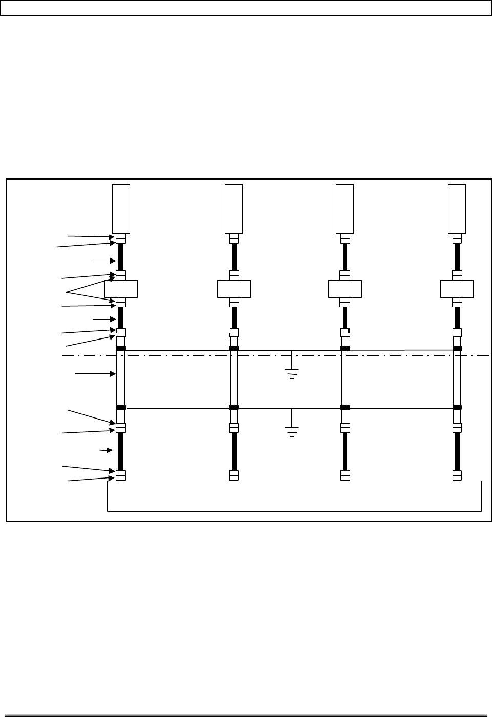
4.2 REMOTE CABLING REQUIREMENTS
Figure 2 is a diagram of the cabling requirements for the Remote sites. The configuration
shown provides corridor coverage. Unlike a standard 3-sector system, which provides a
unique channel for each sector, the TDMA-Over-Microwave system transmits the same
information in both directions. In Figure 2, the Sector 1 and 2 designations are used to
identify the location of components on the tower. Table 4.1 also defines the required
connectors, tower-top LNAs and cable lengths.
Table 4-1 lists the recommended parameters for tower cables, jumper cables, and data link
cables. When selecting tower cables, bigger is better in terms of propagation losses, but not
for weight and wind loading. Table 4-1 defines the minimum diameter of cable required in
order to minimize wind and weight loading on the tower and still meet TransCell 1900TM
system requirements. All RF connections to the Hub or Remote cabinet shall not exceed a
voltage standing wave ratio (VSWR) of 1.5:1.
When using the 3-sector option, another sector's worth of cable materials must be added.
TransCell 1900TM System Installation & Integration Manual 1000462 A
Page 4
TRANSCEPT PROPRIETARY - DATA ON THIS PAGE SUBJECT TO RESTRICTIONS CITED ON COVER AND TITLE
3’ max Coax Cable
6’ max Coax Cable
Remote Unit
Tower Cable
Coax Cable (EST. 6’)
Ground Bar
Ground Bar
Female DIN
Male DIN
Female DIN
Female DIN
Female DIN
Male DIN
Male DIN
Female DIN
Male DIN
Male DIN
Male DIN
SECTOR 1 SECTOR 2
RxP/Tx RxD/Tx
Tower Top
TMA-DD
(LGP TELCOM)
OR
KRY 11219
(ERICSSON)
LNA
PCS
ANT
LNA
PCS
ANT
LNA
PCS
ANT
LNA
PCS
ANT
SECTOR 1 SECTOR 2
RxP/Tx RxD/Tx
RxP/Tx RxD/Tx RxP/Tx RxD/Tx
Figure 2. Tower Cabling Requirements
TransCell 1900TM System Installation & Integration Manual 1000462 A
Page 5
TRANSCEPT PROPRIETARY - DATA ON THIS PAGE SUBJECT TO RESTRICTIONS CITED ON COVER AND TITLE
Table 4-1. Tower Cable Definition.
PCS Tower Cable
Cable Length (ft.) Cable Diameter (in.) Max Cable Loss (dB) Cable Type (Andrew)
< 170 feet 7/8 3.35 dB LDF5-50A
170–231feet 1-1/4 3.35 dB LDF6-50
231–268 feet 1-5/8 3.35 dB LDF7-50A
268–316 feet 2-1/4 3.35 dB LDF12-50
Jumper Cable
3 foot 1/2 0.2 dB LDF4-50A
6 foot 1/2 0.4 dB LDF4-50A
Data Link Cable
<250 feet 5/8 Refer to Appendix A, Figure
A-1 for margin requirements LDF4.5-50A
4.3 MICROWAVE DATA LINK CABLES
Figure 3 depicts the cable interconnects between the Remote Assembly and the data link
antenna. The tower cable is Andrew cable type LDF4.5-50A. The maximum allowable cable
loss for each LDF4.5-50 cable with connectors is defined in Table 4-1. The cabling of the
microwave data link is the same for the Remote site as is for the Hub site. Note that the
antenna requires N type connectors instead of DIN type connectors. See Appendix A for
more data-link antenna installation options.
Remote
Tower Cable
Male DIN
Female N
Male N
H-RX/TX
V-RX/TX
Female DIN
Ground Bar
Ground Bar
H-
Rx
Tx V-
Rx
Tx
Figure 3. Microwave Data Link Cables

TransCell 1900TM System Installation & Integration Manual 1000462 A
Page 6
TRANSCEPT PROPRIETARY - DATA ON THIS PAGE SUBJECT TO RESTRICTIONS CITED ON COVER AND TITLE
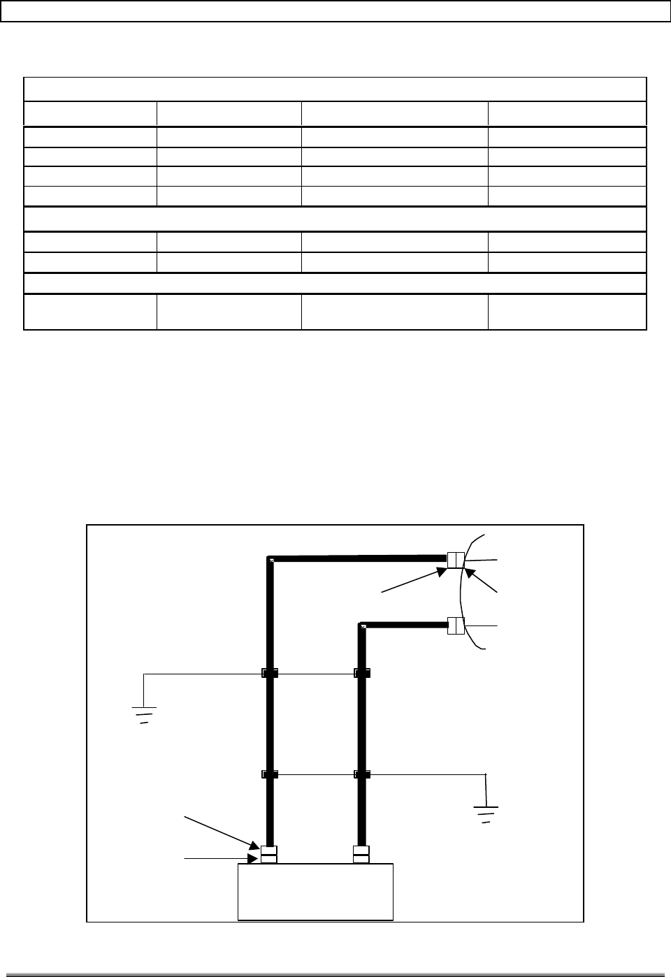
4.4 DATA LINK ANTENNA CLEARANCE
Figure 4 depicts the minimum spacing from the PCS antennas to the data link antenna.
The clearances from the PCS antennas to the data link antenna take into account the
possibility that the PCS antenna may overhang the data link antenna. The clearance from
the top of obstacles to the bottom of the antenna is a requirement that applies to the entire
path from the Remote site to the Hub site. The required clearance is specified in Document
No. 1000143, Table 4, Data Link Requirements.
TransCell 1900TM System Installation & Integration Manual 1000462 A
Page 7
TRANSCEPT PROPRIETARY - DATA ON THIS PAGE SUBJECT TO RESTRICTIONS CITED ON COVER AND TITLE
C/L C/L C/L
C/L
2 or 4 Foot Parabolic
Antenna
2 type N connectors
4' Min 4' Min
Figure 4. Data Link Antenna Clearance
4.5 REMOTE ASSEMBLY INTERCONNECT
Figure 5 is an interconnect diagram between the Remote Assembly and tower cables. The
dashed line indicates that the cable will be routed through underground conduit. The RF
lines shown are Andrew cable type LDF4-50A with the appropriate terminating connectors.
Refer to Table 4-1 for allowable cable loss.
Male DIN
To Data Link
Antenna
Sector 1 RxP/Tx
Sector 1 RxD/Tx
Main
Power
Panel
240vac
Sector 2 RxP/Tx
Sector 2 RxD/Tx
H-RX/TX
V-RX/TX
REMOTE
Female DIN
Figure 5. Remote Interconnect Diagram
TransCell 1900TM System Installation & Integration Manual 1000462 A
Page 8
TRANSCEPT PROPRIETARY - DATA ON THIS PAGE SUBJECT TO RESTRICTIONS CITED ON COVER AND TITLE
4.6 REMOTE PRIME POWER FEED
Figure 6 is a diagram of the prime power distribution for the Remote site. The Remote
Assembly is a standalone unit with its own 125-amp, 240-VAC power panel. Included in the
prime power panel is:
• 40 amp, 2 pole Main Breaker
• 40 amp, 2 pole Auxiliary Breaker,
• Surge Arrestor
• 15 amp, 1 pole AC Outlet Box breaker
• 40 amp, 2 pole PDU breaker
Input prime power requirements are specified in Document No. 1000143, Table 7,
Mechanical/Environmental/Safety Requirements.
Emergency
Generator
Receptacle
100A,
HBL4100B12W
3#6, #6G
Remote
40A Auxiliary Breaker, 2P,
10,000AIC
QO240
40A Main Breaker, 2P,
10,000AIC
QO240
4#8G - 2” RGS Conduit
125A Main Distribution
Panel Board
120/240VAC, 12 Pole
Fused Disconnect Switch
100A, 240V, 2 Pole,
Heavy Duty NEMA 3R
40 A PDU Breaker, 2P,
QO240
15 A AC Outlet Box Breaker, 1P
(QO120)
Surge Arrestor
QO112L125GRB
AC Filter
Block, 1000487P1
240 VAC Line Filters,
1906031P002
Figure 6. Remote Site Prime Power
TransCell 1900TM System Installation & Integration Manual 1000462 A
Page 9
TRANSCEPT PROPRIETARY - DATA ON THIS PAGE SUBJECT TO RESTRICTIONS CITED ON COVER AND TITLE
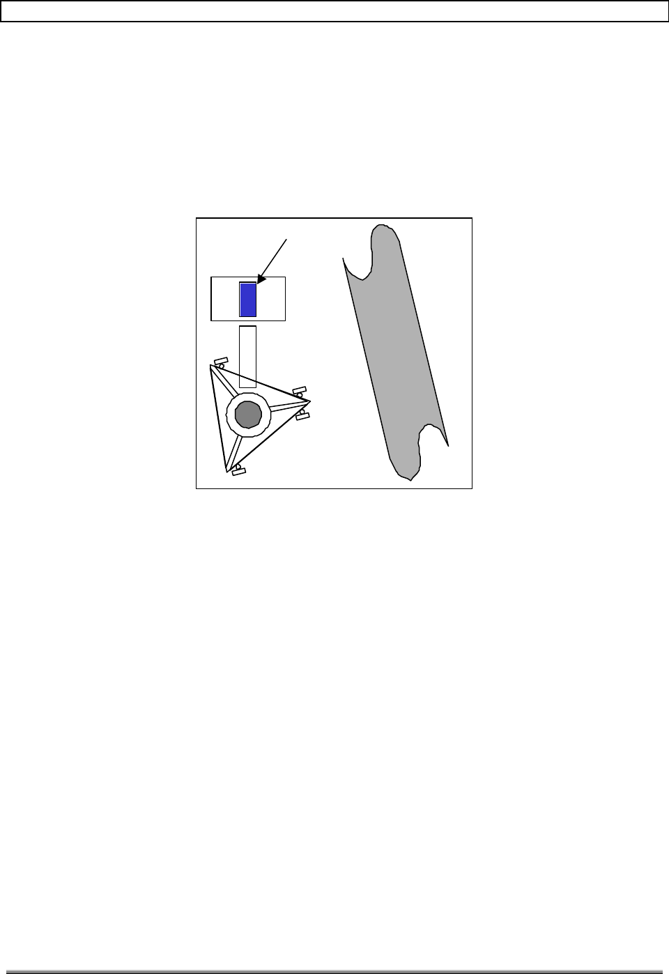
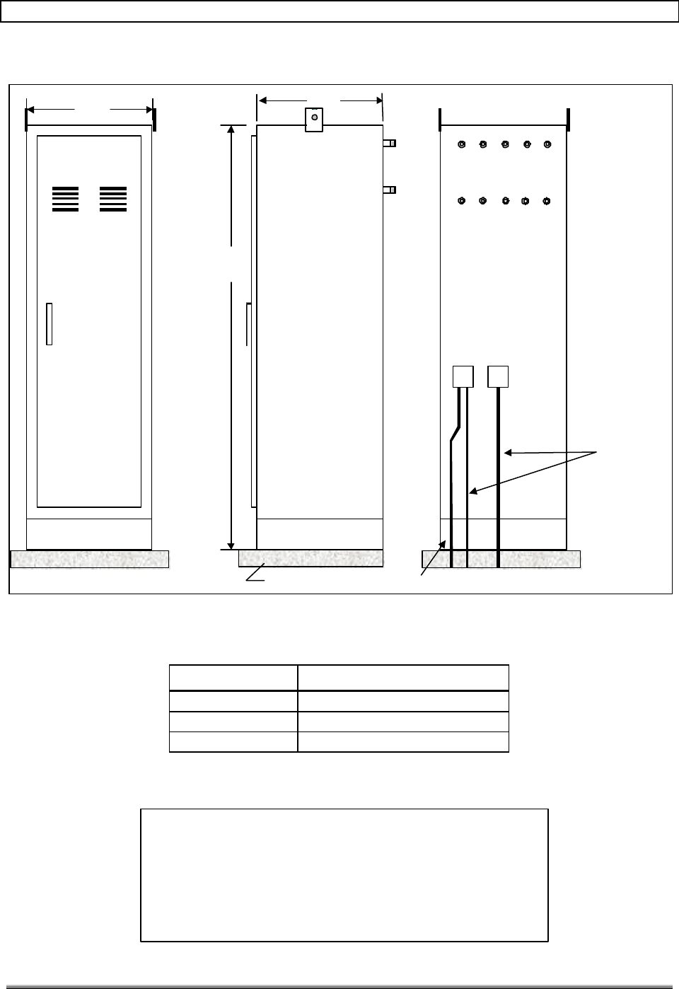
4.7 REMOTE ASSEMBLY OUTLINE DIMENSIONS
Figure 7 is an outline drawing of the Remote Assembly. The main interfaces are the
Emergency Generator Receptacle, 125 Amp Service Panel and eleven RF ports. The Remote
Assembly has its own service panel for distribution of power. The emergency generator
receptacle allows the Remote Assembly to be powered from an external generator. To use
this capability, the generator circuit breaker must be placed in the ON position. When the
generator circuit breaker is ON, the main breaker is turned off, and power flows from the
generator to the Remote Assembly.
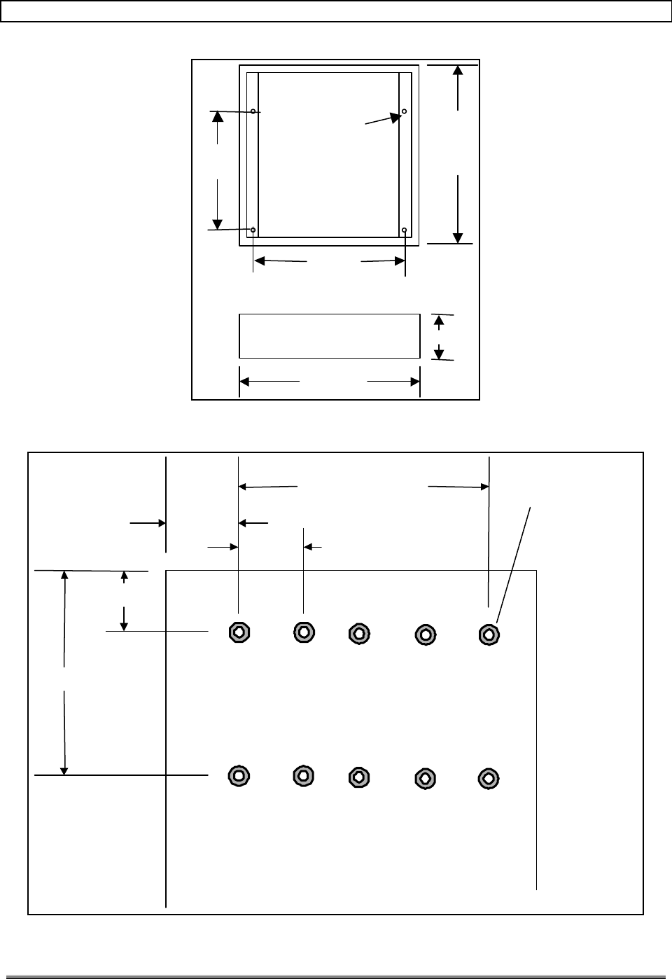
The base of the Remote Assembly is depicted in Figure 8. The base is bolted to the cement
pad first and then the cabinet is placed on it and bolted down with 1/2-inch nuts.
The RF ports are used to interface the Remote Assembly to the PCS Antennas and Data
Link Antenna. Even though three connectors are shown for each sector, only the RxP/Tx
and RxD/Tx ports are used in sectors 1 and 2. Sector 3 is an optional sector that is used
when three-sector coverage is needed. The Tx port in each sector is used only when the 12-
carrier option is implemented. Figure 9 is a diagram that depicts the spacing of the DIN
connectors on the Remote cabinet.
Plug
Surge
Suppressor
Service
Entrance
2” RGS Conduit
Data Link
6 inch mounting base
50”
Access Door
36" 24"
H-
Rx
Tx V-
Rx
Tx
RxP/Tx RxD/Tx TX
78"
Min Pad Size 44” x 32”
Load
Center
Square D
QO112L125GRB
#2 Solid Ground Wire
RxP/Tx RxD/Tx TX
RxP/Tx RxD/Tx TX
Generator
Sector 1 Sector 2
Sector 3
Filter
Block
1000487P1
Figure 7. Remote Outline Drawing
TransCell 1900TM System Installation & Integration Manual 1000462 A
Page 10
TRANSCEPT PROPRIETARY - DATA ON THIS PAGE SUBJECT TO RESTRICTIONS CITED ON COVER AND TITLE
36”
33”
24” 16”
6”
Through hole
For 1/2" bolt
4 Places
Figure 8. Remote Mounting Base
Data Link
Sector 1 Sector 2
Sector 3
H- Tx Rx
V- Tx Rx
RxPTx RxDTx TX
RxPTx RxDTx TX
RxPTx RxDTx TX
5.5”
8.0”
10.0”
4.0”
5.0”
5 EQ SP @ 5.0”
4 EQ SP @ 5.0”
5.0”
DIN Type
Conn
11 places
Figure 9. Connector Spacing
TransCell 1900TM System Installation & Integration Manual 1000462 A
Page 11
TRANSCEPT PROPRIETARY - DATA ON THIS PAGE SUBJECT TO RESTRICTIONS CITED ON COVER AND TITLE
5.0 HUB SITE INSTALLATION
The following section covers the site installation requirements for the Hub unit (donor site).
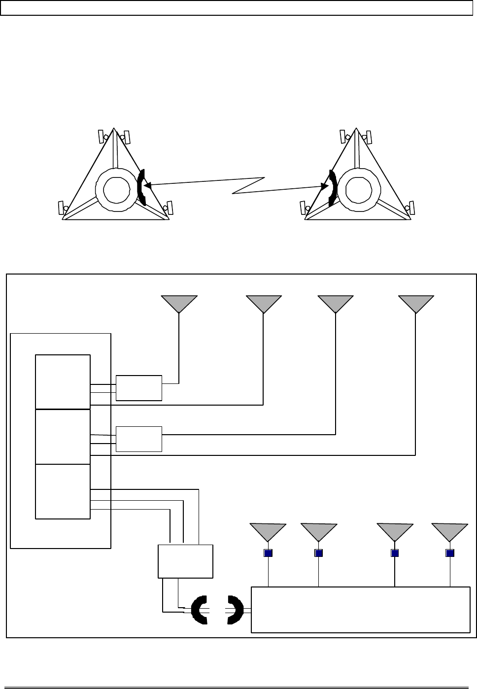
5.1 TOWER TOP VIEW
Figure 10 is an overhead view of the Hub site with respect to a highway when an SCCS is
used. The unit can also be installed inside a shelter or outside the shelter. The two sectors
shown transmit and receive the same information due to the signals being combined and
split at the SCCS. One antenna is used to transmit and receive RF signals and the other
antenna is used for receive only. The third sector in the SCCS is utilized to interface to the
antennas at the donor site. The first and second sectors in the SCCS are donated to the
repeater sites.
Sector 1
Sector 2
Hub
SCCS
Highway
Figure 10. Overhead View of Hub Site
TransCell 1900TM System Installation & Integration Manual 1000462 A
Page 12
TRANSCEPT PROPRIETARY - DATA ON THIS PAGE SUBJECT TO RESTRICTIONS CITED ON COVER AND TITLE
5.2 HUB CABLING REQUIREMENTS
Figure 11 is a diagram of the cabling requirements for the Hub sites. The configuration
shown provides corridor coverage for a non-duplexed SCCS to Hub interface. Unlike a
conventional SCCS system which provides a unique channel for each sector, the SCCS
transmits the same information in both directions via the PCS antennas (Sector 1, Sector
2), meanwhile feeding signals from its other two sectors to the Hub cabinet for data link
transmission.
Figure 11 also defines the required connectors, tower top LNAs and cable lengths. The
customer determines the type of tower cable (Table 4-1 should be used as reference). Also
depicted in the diagram are the duplexer and splitters that the customer must configure
with the SCCS to provide corridor coverage. The customer will also have to ensure that the
SCCS can power the tower-top LNAs.
3’ max Coax Cable
6’ max Coax Cable
SCCS
Tower Cable
Coax Cable (EST. 6’)
Ground Bar
Ground Bar
Female DIN
Male DIN
Female DIN
Female DIN
Female DIN
Male DIN
Male DIN
Female DIN
Male DIN
Male DIN
Male DIN
SECTOR 1 SECTOR 2
Rxp/Tx RxD RxD
RxP/Tx
Tower Top
Tx RXP RXD
Duplexer
TMAD
(LGP)
or
KRC131085/1
(Ericsson )
Splitter
Splitter
LNA
PCS
ANT
LNA
PCS
ANT
LNA
PCS
ANT
LNA
PCS
ANT
TMA-DD
(LGP TELCOM)
OR
KRY 11219
(ERICSSON)
ANTPD218D
(Telewave)
Male DIN
Female DIN
Hub
Tx RXP RXD Tx RXP RXD
SECTOR 1 SECTOR 2
Figure 11. Cabling Requirements for Hub Site
TransCell 1900TM System Installation & Integration Manual 1000462 A
Page 13
TRANSCEPT PROPRIETARY - DATA ON THIS PAGE SUBJECT TO RESTRICTIONS CITED ON COVER AND TITLE
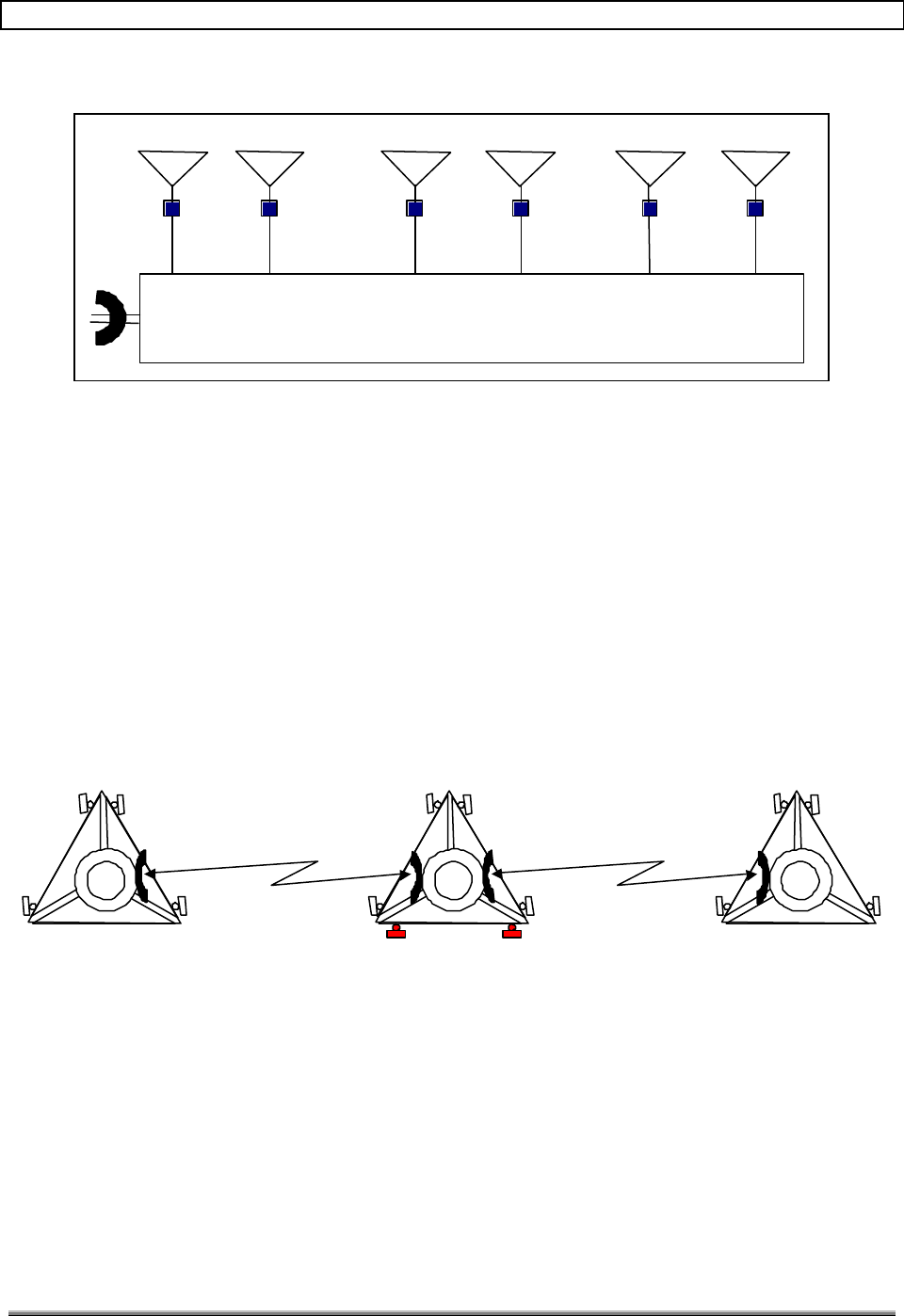
5.3 HUB ASSEMBLY INTERCONNECT
Figure 12 is an interconnect diagram between the SCCS, Hub cabinet and tower cables.
The dotted signal lines indicate that the power line will be routed through conduit. The
remaining RF lines are Andrew type LDF4-50A with the appropriate terminating
connectors.
RXD RXP TX
V.35
RXD RXP TX
RXD
RXP
TX
TX
RXP
RXD
V.35
RXD
RXP
TX
SCCS
Sector 2
Sector 1
Male DIN
Male DIN
Male DIN
To Data Link
Antenna
Sector 1
To Data Link
Antenna
Sector 2
1/2 Hub
1/2 Hub
LDF4-50A
H-
R
X/
TX
V-
R
X/
TX
H-
R
X/
TX
V-
R
X/
TX
Electronics 115vac
4x4
J-Box
4x4
J-Box
Main
Power
Panel
240vac
Tower
Cable
Interface
Female DIN
Sector 3
Male DIN
To PCS
Antennas
Sector 1
Sector 2
Note: Even though 2 Hub boxes are shown in the
diagram, everything resides in one cabinet.
Figure 12. Interconnect Diagram for Hub Site
5.4 BIAS TEE ALARMING
The Lucent Base Station will alarm if no current draw is detected at the donor sector's Dx
FRU. To disable this alarm, install a m-f 9-pin D shell plug, with a jumper on pins 3 and 4,
at the Dx FRU J10 receptacle.
The Ericsson base station has current monitoring on each bias tee port. The bias tee port is
used to power a single tower-top LNA. When a sector on the base station is split to run
antennas on two sectors, each bias tee port drives two tower top LNAs as a result. The
doubling of current demand causes an alarm to be reported. One solution to the problem is
to combine two bias tee outputs to drive one bias tee. Figure 13 is a diagram of one of the
options to solve the tower-top amplifier problem.
TransCell 1900TM System Installation & Integration Manual 1000462 A
Page 14
TRANSCEPT PROPRIETARY - DATA ON THIS PAGE SUBJECT TO RESTRICTIONS CITED ON COVER AND TITLE
2A
3A
2B
3B
Bias Tee
P/O Base Station
Bias Tee
DC
RFin RFout
RxP
RxD
Split to Two
Tower-Top LNAs
Split to Two
Tower-Top LNAs
= SMA Female
= SMA Male
SMA Tee
Assembly Needed
(2 each base station)
P/O Base Station
DC
RFin RFout
6” Male-to-Male
Cable
Figure 13. Solution for Tower Top Amplifier Alarming
5.5 HUB PRIME POWER FEED
Figure 14 is a diagram of the power distribution for a typical Hub Site. To maintain a single
Emergency Generator Receptacle to power the SCCS and Hub, a main power panel is
required. Contained within the panel will be a 20-amp, 120-VAC breaker for the Hub
cabinet; a 100-amp breaker for the SCCS; a 100-amp or 200-amp main breaker; and a 100-
amp generator breaker. If a 20-amp circuit is open in the SCCS or in the shelter's circuit
panel, the power panel would not be required.
Along with the main power panel, a surge arrestor is required to protect the Hub's
Assemblies and SCCS from voltage transients on the main power lines.
TransCell 1900TM System Installation & Integration Manual 1000462 A
Page 15
TRANSCEPT PROPRIETARY - DATA ON THIS PAGE SUBJECT TO RESTRICTIONS CITED ON COVER AND TITLE
Fused Disconnect Switch
100A, 240V, 2 Pole,
Heavy Duty NEMA 3R
20A Breaker, 1P, 115 VAC
Emergency
Generator
Receptacle
100A
100A Main Distribution
Panel Board
120/240 VAC, 20 Pole
Surge
Arrestor
SCCS
100A Main Breaker
2P, 10,000 AIC
Master Hub
2#12,#12G-3/4”C
Power Panel
Figure 14. Prime Power Feed for Hub Site
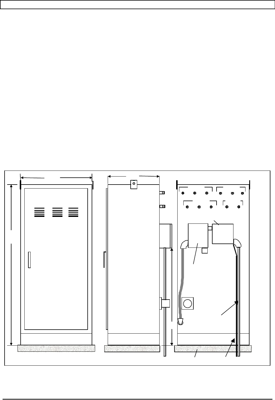
5.6 HUB ASSEMBLY OUTLINE DIMENSIONS
Figure 15 is an outline drawing of the Hub Assembly. One side of the Hub Assembly has
two 4-inch x 4-inch junction boxes labeled PWR and COM. The junction boxes allow the
installer to make all necessary connections to the Hub without having to open the unit.
When the PWR junction box is opened for the first time, the installer will find flying leads
for connection of electronics power and a grounding stud for safety ground. Each lead is
labeled as to its connection point. Table 5-1 defines the label markings.
The COM junction box contains one 25-pin D connector for the V.35 connection. When the
installer routes the communication cable through the conduit to the Hub, the cable will be
terminated with the proper connectors by the installer.
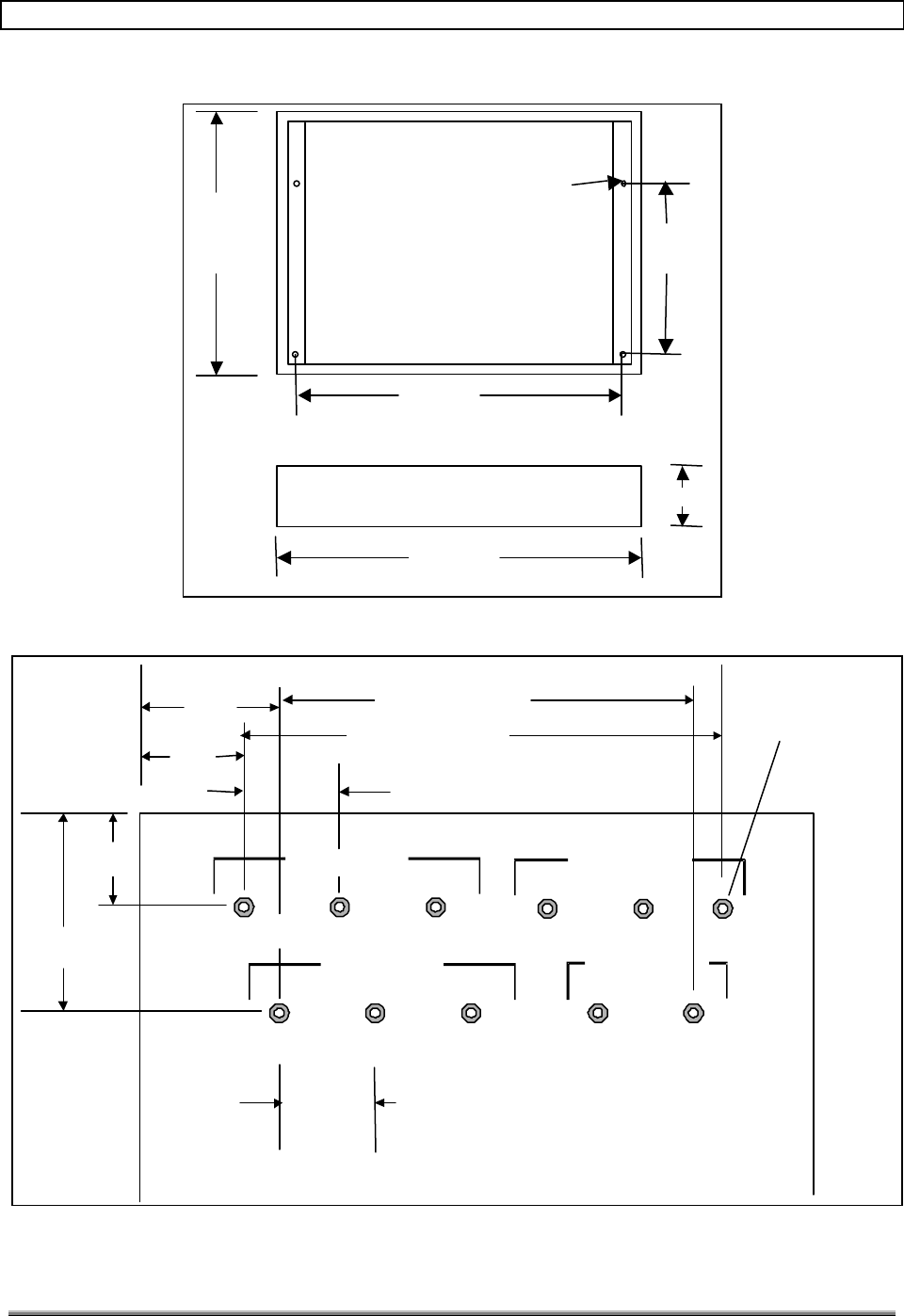
The mounting base for the Hub enclosure is shown in Figure 16. The base is bolted to the
concrete pad, and then the cabinet is placed on it. If the Hub enclosure is mounted inside a
shelter, the base is not required. Figure 17 depicts the DIN connectors on the Hub cabinet.
TransCell 1900TM System Installation & Integration Manual 1000462 A
Page 16
TRANSCEPT PROPRIETARY - DATA ON THIS PAGE SUBJECT TO RESTRICTIONS CITED ON COVER AND TITLE
6 inch mounting base
Access Door
24"
78"
PWR COMM
Data Link
H-
Rx
Tx V-
Rx
Tx Rx
PRx
DTx
Sector 1
H-
Rx
Tx V-
Rx
Tx Rx
PRx
DTx
Sector 2
24"
Min Pad Size 32” x 32” #2 Solid Ground Wire
3/4” Conduit
Figure 15. Outline Dimensions of Hub Assembly
Table 5-1. Input Power Labeling.
Device Wire Marking
Electronics ELEC
Return or neutral NEUT
Safety Ground Green Wire with Yellow Stripe
NOTE
A duplexer transmitter solution requires a hub duplexer tray
as found in the G2 hub configuration. In the G2 configuration,
connect BTS Tx/Rx primary cable to "Rx Primary Hub"
antenna port, and the BTS Tx/Rx diversity cable to "Rx
Diversity Hub" antenna port and weather-seal the unused Tx
ports.
TransCell 1900TM System Installation & Integration Manual 1000462 A
Page 17
TRANSCEPT PROPRIETARY - DATA ON THIS PAGE SUBJECT TO RESTRICTIONS CITED ON COVER AND TITLE
24”
21”
16”
24 “
6”
Through hole
For 1/2" bolt
4 Places
Figure 16. Hub Mounting Base
H-RxTx
V-RxTx
RxP
RxD
Tx
Sector 1
H-RxTx
V-RxTx
RxP
RxD
Tx
Sector 2
5.0”
12.0”
4.0”
4.0”
4 EQ SP @ 4.0”
DIN Type
Conn
10 places
Figure 17. Connector Spacing

TransCell 1900TM System Installation & Integration Manual 1000462 A
Page 18
TRANSCEPT PROPRIETARY - DATA ON THIS PAGE SUBJECT TO RESTRICTIONS CITED ON COVER AND TITLE
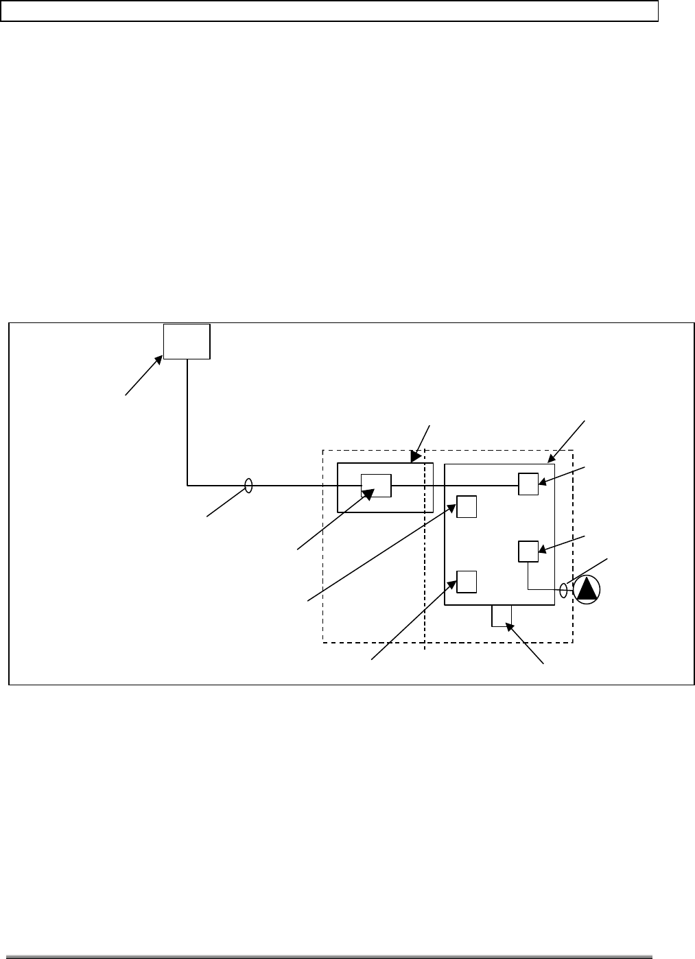
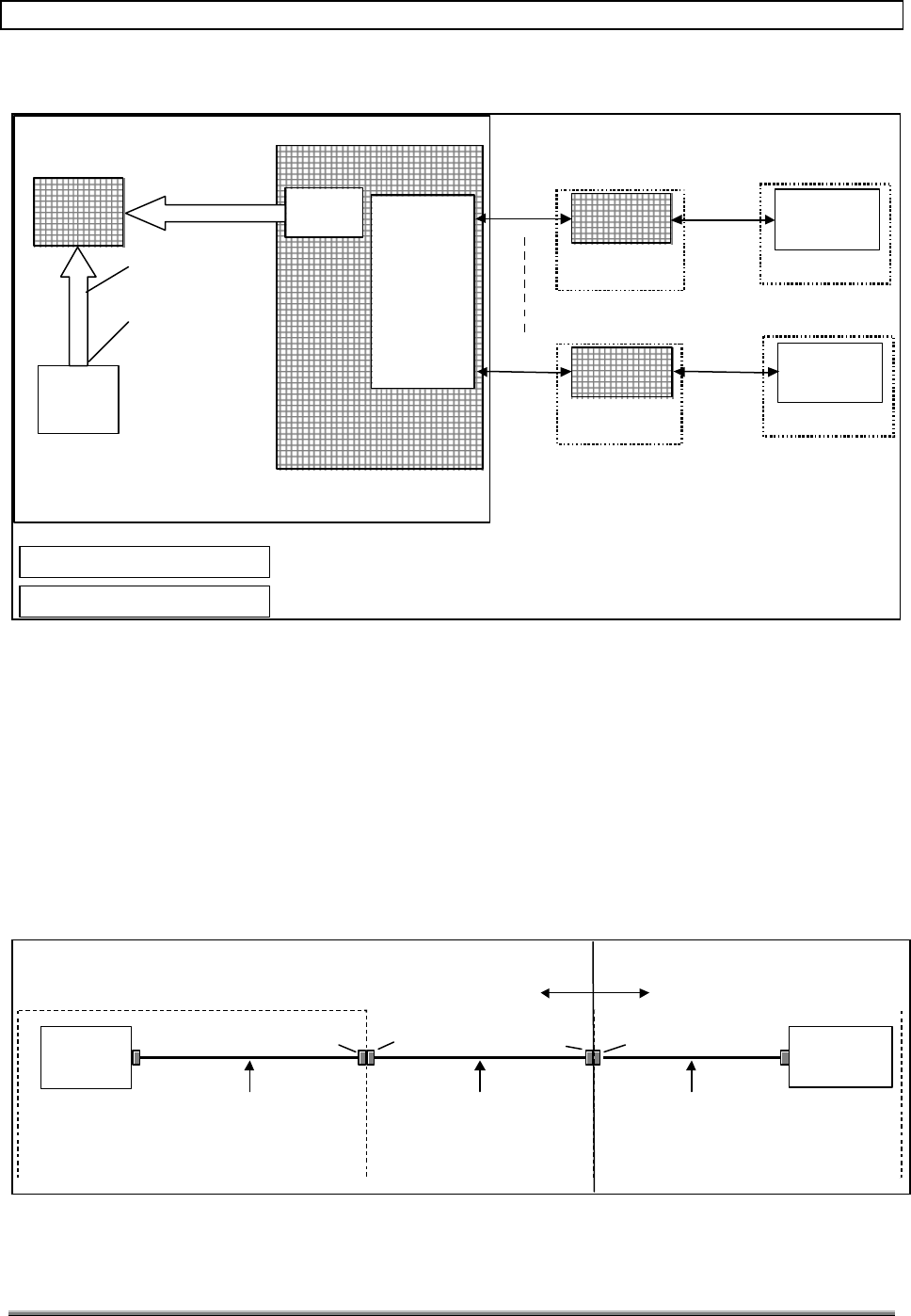
5.7 COMMUNICATION CONCEPT
Figure 18 depicts a concept for communication between a number of Hub sites and the
existing network. The term concept indicates that this is one possible option for connecting
the Operation, Administration and Maintenance (OA&M) interface to the network. The
following are explanations for the major blocks:
1. Hub: Each Hub contains a V.35 interface and a Signal Processing Module (SPM)
Ethernet (10BaseT) interface.
SCCS: Each SCCS contains a CSU as a minimum. The CSU must be updated to a
CSU/DSU to provide the TransCell 1900TM access to a time slot (DS0) selectable by the
customer. A DS0 line is needed for communications from a TransCell 1900TM site to be
seen at the SEM. In order to peel a DS0 off of an existing fiber back-haul at the donor
(Hub) site, a few CSU/DSU parameters must be modified to ensure smooth operation of the
TransCell 1900TM. A typical setup checklist is shown below.
Table 5-2. Data Back-haul Configuration Checklist.
Parameter Desired Value Hub Site Check Y/N Switch Site Check Y/N
Data Speed 64K 64K? 64K?
DS0 Port Mapping User configurable,
must match both
ends.
Same as switch? Same as Hub?
Clock Hub: network
Switch: internal
Network? Internal?
Port Hub: V.35
Switch: Serial port
V.35 port activated? Serial port activated?
Protocol Encapsulation
PPP N/A Encapsulation PPP at
Router Serial Port?
2. MSC (Master Station Controller): All information from the Hub-Remote Pair (HRP)
is transferred in ASCII format over the T1 lines to the MSC. The information for
both the Hub and Remote Assembly in each HRP is sent from the Hub to the
upgraded CSU/DSUs. The outputs of the CSU/DSUs are routed to the MSC for
processing. At the MSC end, the CSU/DSU outputs are combined onto one T1 and
fed into a router. The extracted OA&M data is then sent to an Ethernet Hub and
routed to the OA&M interface (SEM). The SEM processes/displays operational
information and provides a control point for the operation of all the HRPs. If a
problem is detected, alarm information is sent automatically to the SEM, where it is
made available to the Operational Support System (OSS) as tab-delimited ASCII
data via TCP/IP.
NOTE
The customer must assign two IP addresses to each HRP.
TransCell 1900TM System Installation & Integration Manual 1000462 A
Page 19
TRANSCEPT PROPRIETARY - DATA ON THIS PAGE SUBJECT TO RESTRICTIONS CITED ON COVER AND TITLE
Master Hub 1
SCCS
Encapsulation PPP, 64K
MSC
SEM
CustomerCustomer
Network
Network 72047204
Router
Router
CSU/DSU
CSU/DSU
PA-MC-4T1
PA-MC-4T1
Alarm feedback
and system control
RJ45 10BaseT
Ethernet
connection
CSU/DSUCSU/DSU
SCCS
CSU/DSUCSU/DSU
T1-1
T1-4
SPM
Master Hub 4
SPM
Customer ownership
Transcept ownership
64K V.35
Figure 18. Communication Concept Block Diagram
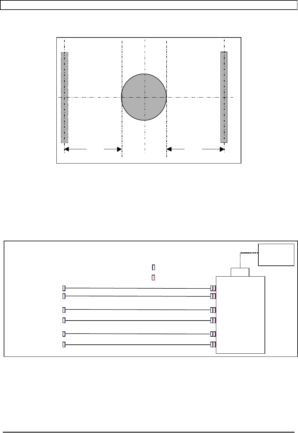
5.8 V.35 CABLING SCHEME
Figure 19 is a diagram of the cables needed to route the V.35 signals from the CSU/DSU in
the SCCS to the Hub. The customer shall supply the cabling that connects the CSU/DSU to
the Transcept Enclosure V.35 cable interface (1000389).
After the cable is routed through the conduit into the Hub 4-inch x 4-inch junction box, a
25D connector (plug) will be attached. The Hub Enclosure v.35 interface cable shown below
will be installed at Transcept prior to shipment. For a pin-out of this cable (1000389), see
the TransCell 1900TM SEM / HUI User’s Guide.
CSU/DSU SPM
HUB
SCCS
Customer TRANSCEPT
Kentrox 72756 Kentrox PN: 95010054
1000389G1
Through conduit, where necessary.
(Pinout is 25D jumper, “Straight”)
Female 25D
Male 25D Male 25D Female 25D
Figure 19. CSU/DSU to Router Cables
TransCell 1900TM System Installation & Integration Manual 1000462 A
Page 20
TRANSCEPT PROPRIETARY - DATA ON THIS PAGE SUBJECT TO RESTRICTIONS CITED ON COVER AND TITLE
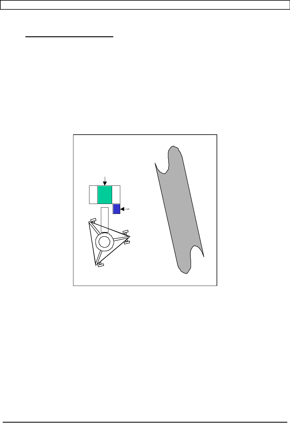
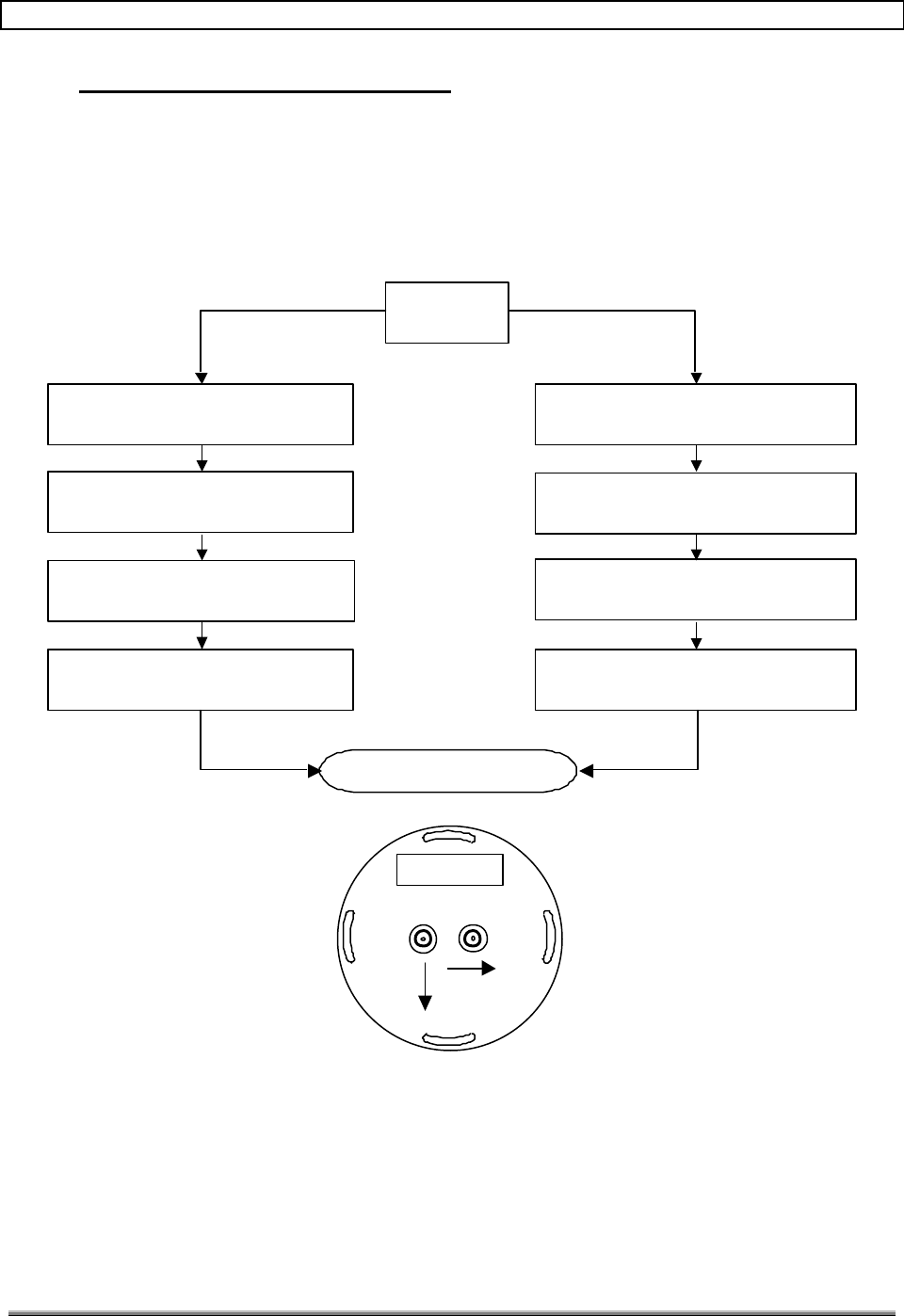
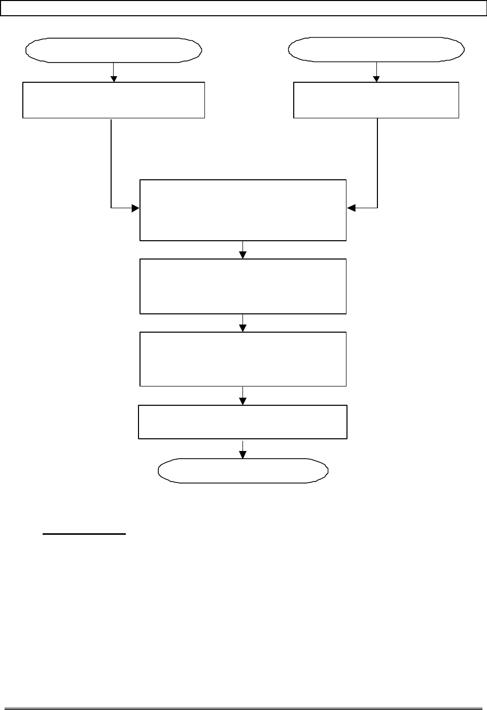
6.0 DATA LINK ANTENNA ALIGNMENT
Figures 20 and 21 are flow diagrams for the installation of the data link antennas (DLAs)
by The customer.
6.1.1 Coarse Alignment
Figure 20 depicts the initial alignment procedure that can be performed by the tower
climbers.
DLA
Alignment
Hub Side Remote Side
Obtain Hub to Remote Compass
Bearing from Site Map
Mount DLA at Proper
Height and side of Tower
Align DLA to
Compass Bearing
Obtain Remote to Hub Compass
Bearing from Site Map
Mount DLA at Proper
Height and side of Tower
Align DLA to
Compass Bearing
End Of Coarse Alignment
Mount feed in DLA with label
facing upright (see sketch below) Mount feed in DLA with label
facing upright (see sketch below)
RADIOWAVES
Label
DLA MOUNTING SURFACE
Figure 20. DLA Coarse Alignment
6.1.2 Final Alignment
Figure 21 depicts the final adjustment procedure. The final adjustments will require an RF
transmitter and two RF receivers to aid in optimizing the path loss. A 5.8 GHz RF
generator may be used as the RF transmitter and a spectrum analyzer or power meter may
be used as the RF receiver.
TransCell 1900TM System Installation & Integration Manual 1000462 A
Page 21
TRANSCEPT PROPRIETARY - DATA ON THIS PAGE SUBJECT TO RESTRICTIONS CITED ON COVER AND TITLE
Vary Horz. And Vert.
Adjustments on each DLA
for Max. Power on V-Rx/Tx
Cable on Hub
Verify power reading on V-Rx/Tx is
>-56dBm for tower spacing >3.5miles
and >-50dBm for <3.49miles
End of Date Link Alignment
Connect Power Meter to H-Rx/Tx.
And V-Rx/Tx Data Link Cables Connect 5.8 GHz, +26dBm CW
Source to V-Rx/Tx Cable
From Remote Coarse Alignment
From Hub Coarse Alignment
Rotate Antenna feed on one antenna
for max power on V-Rx/Tx cable and
min on H-Rx/Tx cable.
Verify H-Rx/Tx is at least 25
dB less than V-Rx/
Tx
Figure 21. Final DLA Alignment
7.0 RF PLANNING
To better understand how to implement the TransCell 1900TM system with regard to RF
planning requirements, the following paragraphs are included to give more detail than has
been covered in previous documentation.
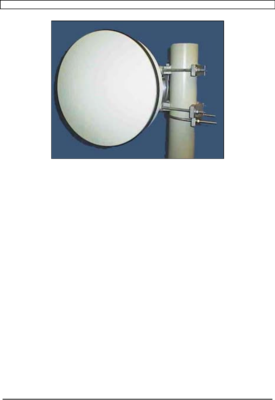
7.1 DATA LINK ANTENNAS
The standard antenna that is sold as part of the TransCell 1900TM system is a solid
parabolic dish antenna. See Figure 22. See Appendix A for data-link antenna installation
options.
TransCell 1900TM System Installation & Integration Manual 1000462 A
Page 22
TRANSCEPT PROPRIETARY - DATA ON THIS PAGE SUBJECT TO RESTRICTIONS CITED ON COVER AND TITLE
Figure 22. Two Foot Parabolic Dish (example)
The antenna comes complete with a radome to cut down on wind loading and all the
mounting hardware to attach the antenna to a pole with maximum diameter of four inches.
TransCell 1900TM System Installation & Integration Manual 1000462 A
Page 23
TRANSCEPT PROPRIETARY - DATA ON THIS PAGE SUBJECT TO RESTRICTIONS CITED ON COVER AND TITLE
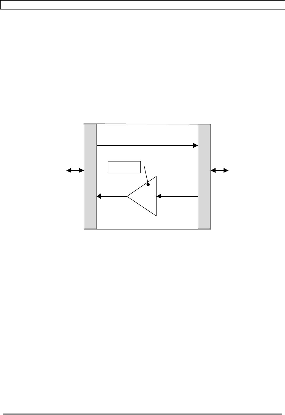
7.2 RF PLANNING MODEL
7.2.1 PCS Link Budget
The TransCell 1900TM system is simple to implement into a link budget. In the forward
path, the repeater is transparent to the link budget. For the six-carrier system, when the
BTS outputs 40 dBm into the Hub cabinet, the remote cabinet will output 40 dBm. In the
reverse path, the repeater amplifies the signal by 10 dB (see Figure 23). If the input to the
remote cabinet is -110 dBm, the power level output from the remote unit will be -100 dBm
nominal. The TransCell 1900TM system can be thought of as a tower-top amplifier with no
forward insertion loss.
Base Station PCS
Antennas
10 dB
Ampl
TransCell 1900TM System
Forward
Reverse
Nominal
Figure 23. RF Model For TransCell 1900TM System
7.2.2 Data Link Budget
The TransCell 1900TM system is designed to work with tower spacing up to 12 miles. As
long as the requirements of paragraph 4.3 are met, the data link will operate reliably. If a
Lucent Base Station is used, however, a delay issue must be mitigated at data-link spans
measuring over nine miles. See Paragraph 9.2.4 for details.
7.2.3 Alternate Installation schemes
This section depicts alternate ways to implement the TransCell 1900TM system into a
network. The following paragraphs illustrate how flexible the TransCell 1900TM system is
in solving coverage needs.
The term sector may be confusing when looking at the diagrams. The term sector is used in
the following senses:
a. Each of the three faces of a tower is referred to as a sector. As there typically has
been a one-to-one correspondence between the tower faces and the SCCS
connections, the term sector has carried into the SCCS.
b. When looking at the repeater sites (where the remote cabinet is located), the term
sector represents the side of the tower.
TransCell 1900TM System Installation & Integration Manual 1000462 A
Page 24
TRANSCEPT PROPRIETARY - DATA ON THIS PAGE SUBJECT TO RESTRICTIONS CITED ON COVER AND TITLE
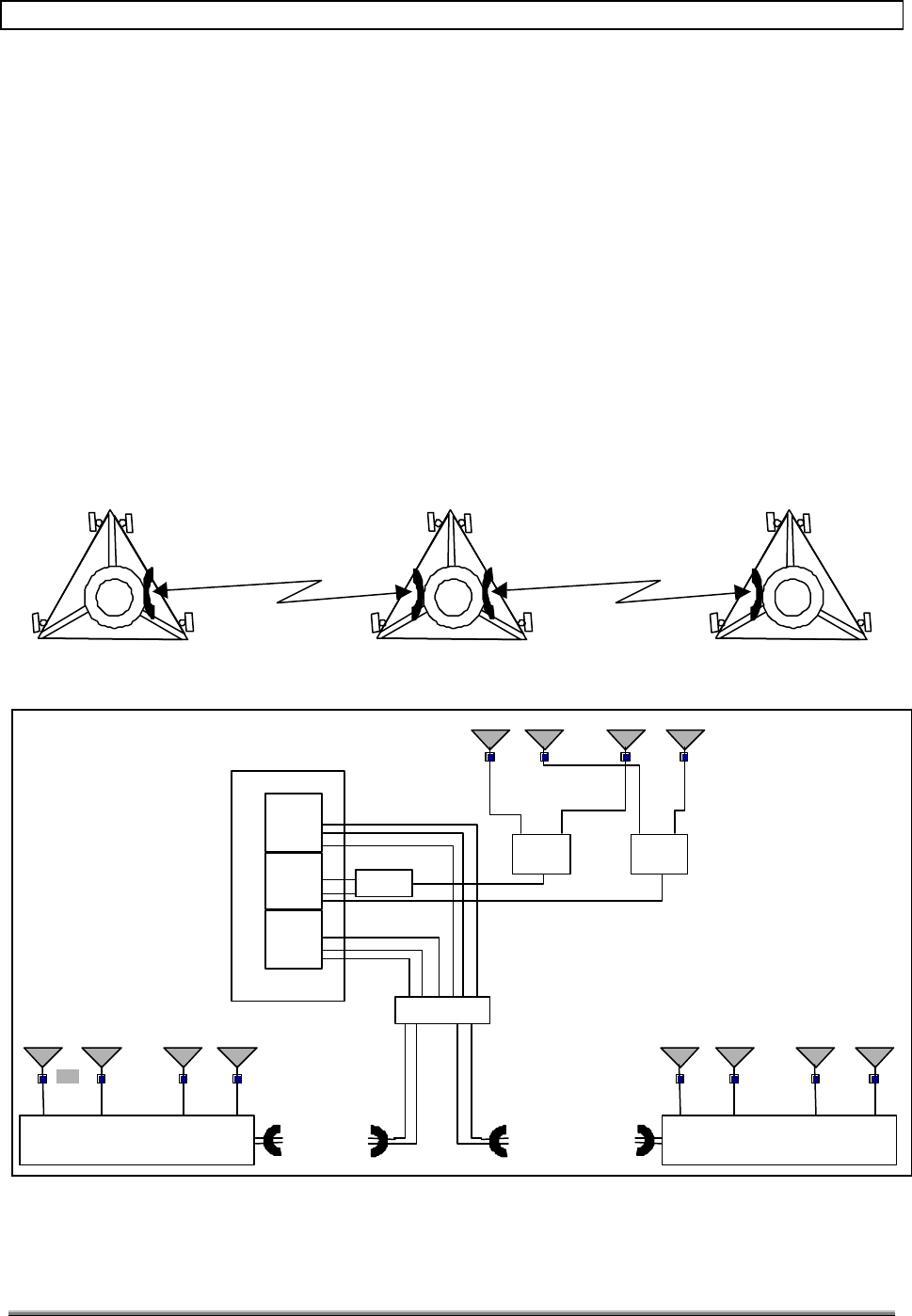
7.2.3.1 Standard Corridor Coverage
The term standard coverage refers to the original design concept of providing corridor
coverage along a highway. Figure 24 is a top-down view of this implementation. The donor
site is the middle tower and the two end towers are the repeater sites. Two of the sectors in
the SCCS are microwave linked to the repeater sites and the third sector is run to the
antennas on the tower. Figure 25 is a block diagram of the donor and repeater sites. At the
donor site, the primary receive and transmit ports are duplexed together, split, connected to
a tower-top LNA and run to antennas that are in separate sectors. The diversity receive
port is split, connected to a tower-top LNA and run to antennas that are in separate sectors.
At the repeater site, there is a separate cable for each antenna. Prior to the antenna, a
tower top amplifier is used to set the noise figure at the top of the tower. Duplexing and
splitting are done internal to the remote cabinet. Each sector transmits the same PCS
signals in sectors 1 and 2.
The power out of the remote cabinet is 10 watts per cable or antenna. Transmit power out
of the SCCS is typically 10 watts. After splitting, the power is cut in half. The power loss
must be included in the link budget.
Figure 24. Top View of Standard Installation
Base Station
Sector 1
Sector 3
Sector 2
RxP
Tx
RxD
RxP
Tx
RxD
RxP
Tx
RxD
Sector 1 Sector 2
SPLITTER SPLITTER
DUPLEXER
HUB
RxP/Tx RxD
Sector 1Sector 2 Sector 1 Sector 2
RemoteRemote
LNA LNA
LNA
Figure 25. Block Diagram of Hub and Remote Installation
TransCell 1900TM System Installation & Integration Manual 1000462 A
Page 25
TRANSCEPT PROPRIETARY - DATA ON THIS PAGE SUBJECT TO RESTRICTIONS CITED ON COVER AND TITLE
7.2.3.2 Single Repeater Installation
In some installations only one repeater will be used due to either ending a stretch of towers
with a donor site or because a higher capacity base station is needed on the next tower.
Figure 26 is a top-down view of a single repeater site. Figure 27 is a block diagram of the
donor and repeater site. This setup assumes that corridor coverage is required. No splitters
are required because the RF lines can be run directly to the PCS antennas.
Donor Site Repeater Site
Figure 26. Top View of Single Repeater Installation
Base Station
Sector 1
Sector 3
Sector 2
RxP
Tx
RxD
RxP
Tx
RxD
RxP
Tx
RxD
Sector 1 Sector 2
HUB
Sector 1 Sector 2
Remote
LNA
Duplexer
Duplexer
Figure 27. Block Diagram of Hub and Remote Installation

TransCell 1900TM System Installation & Integration Manual 1000462 A
Page 26
TRANSCEPT PROPRIETARY - DATA ON THIS PAGE SUBJECT TO RESTRICTIONS CITED ON COVER AND TITLE
7.2.3.3 Three Sector Repeater
Figure 28 is a diagram of a three-sector repeater. Implementing this scheme mainly
involves adding another sector’s worth of antennas and LNAs. Even though three sectors
are shown, the same channels are seen by all three sectors. There are not separate channels
for each sector. Even with the added sector, the RF transmit power is still 10 watts per
carrier.
TransCell 1900TM System Installation & Integration Manual 1000462 A
Page 27
TRANSCEPT PROPRIETARY - DATA ON THIS PAGE SUBJECT TO RESTRICTIONS CITED ON COVER AND TITLE
Sector 1 Sector 2 Sector 3
LNA
Remote
RxP/Tx RxD/Tx RxP/Tx RxD/Tx RxP/Tx RxD/Tx
Figure 28. Block Diagram of Three Sector Remote
7.2.3.4 Three Sector Scheme at Donor Site
Figure 29 is a top-down view of the three-sector approach on the donor site. Even though
only the donor site has three sectors, the repeater site could also have three sectors. Figure
30 is a block diagram depicting a three-sector donor site and two-sector repeater site. The
approach in this scheme is to minimize the RF loss from splitting one sector into three
sectors.
This approach splits one sector from the SCCS to two repeaters. Splitting the transmit
power into the Hub reduces the transmit power by 3 dB. This is overcome by having the
capability to adjust the output power of the repeater. A side note from this scheme is that
two repeaters now share the channels from one SCCS sector. To maintain 6-carrier
capability in both repeaters, the SCCS will need 12 radios.
Donor Site
Repeater Site Repeater Site
PCS Antenna
Microwave Link
Figure 29. Top View of Three Sector Donor Site
TransCell 1900TM System Installation & Integration Manual 1000462 A
Page 28
TRANSCEPT PROPRIETARY - DATA ON THIS PAGE SUBJECT TO RESTRICTIONS CITED ON COVER AND TITLE
Base Station
Sector 1
Sector 3
Sector 2
RxP
Tx
RxD
RxP
Tx
RxD
RxP
Tx
RxD
Sector 1 Sector 2
SPLITTER SPLITTER
DUPLEXER
HUB
RxP/Tx RxD
Sector 1Sector 2 Sector 1 Sector 2
RemoteRemote
LNA LNA
LNA
DUPLEXER
Sector 3
Splitter
Figure 30. Block Diagram of Three Sector Donor Site
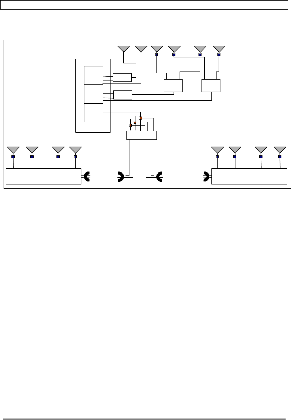
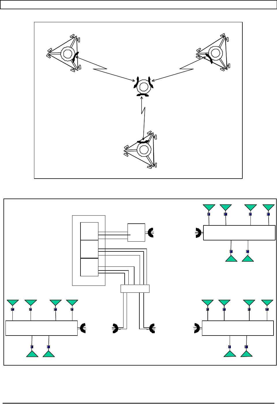
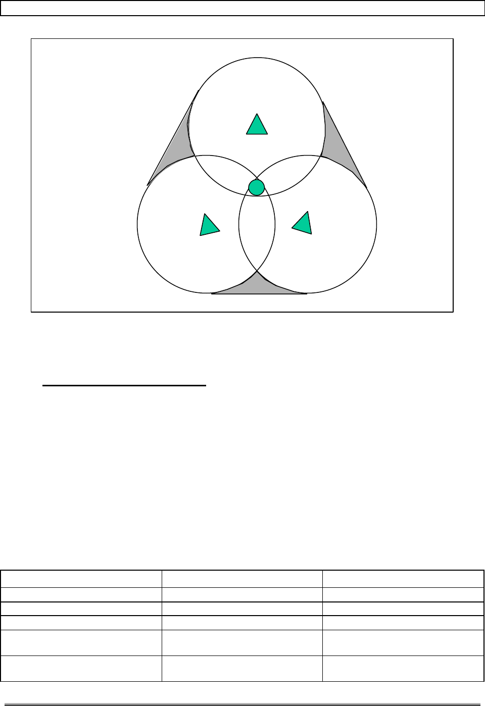
7.2.3.5 Large Radius Coverage
Figure 31 is a unique approach that gives three-sector type coverage without sacrificing any
losses in transmit power. The idea is to locate an SCCS in the middle and to donate the
three sectors to three repeaters. There are no PCS antennas at the donor site.
Figure 32 is a block diagram of the large radius coverage approach. This approach requires
two Hub cabinets because each Hub cabinet can control a maximum of two remote cabinets.
Three sectors are used on each repeater site to optimize coverage. The forward power out of
each of the remote cabinets is 10 watts.
This approach allows for a very large radius of coverage from one SCCS. Figure 33 gives an
idea of what type of coverage can be achieved. The gray area may have degraded coverage.
The limiting factor in this approach would be the sensitivity of the phone. Assuming the
sensitivity of the phone is 6 miles, the radius of coverage from the SCCS would be 12 miles.
This approach would be best for rural areas due to the large radius of coverage, while the
approach in paragraph 7.2.3.1 is best for highway coverage.
TransCell 1900TM System Installation & Integration Manual 1000462 A
Page 29
TRANSCEPT PROPRIETARY - DATA ON THIS PAGE SUBJECT TO RESTRICTIONS CITED ON COVER AND TITLE
Donor Site
Repeater Site Repeater Site
Repeater Site
Figure 31. Top View of Large Radius Coverage Scheme
Base Station
Sector 1
Sector 3
Sector 2
RxP
Tx
RxD
RxP
Tx
RxD
RxP
Tx
RxD
HUB
Sector 1Sector 2 Sector 2
RemoteRemote
LNA
Sector 1
LNA
Sector 3
LNALNA
Sector 2
Remote
Sector 1
LNA
Sector 1
LNA
Hub
Sector 3
Figure 32. Block Diagram of Large Radius Coverage
TransCell 1900TM System Installation & Integration Manual 1000462 A
Page 30
TRANSCEPT PROPRIETARY - DATA ON THIS PAGE SUBJECT TO RESTRICTIONS CITED ON COVER AND TITLE
Repeater
Repeater
Repeater
Donor
Figure 33. RF Coverage for Large Radius Coverage
8.0 HRP SYSTEM INTEGRATION
This section provides procedures and information used to configure and verify operation of
the TransCell 1900TM Hub/Remote Pair (HRP) for use in a wireless network.
8.1 BASE STATION CONFIGURATION
8.1.1 BTS/SCCS Parameter Modifications
Proper operation of the TransCell 1900TM system within a conventional wireless network
requires certain base station parameters to be adjusted. Table 8-1 depicts a parameter
change list for Ericsson, Lucent, and Nortel base stations for use with TransCell 1900TM
deployments.
Table 8-1. BTS/SCCS Parameter Modifications.
Manufacturer Parameter Required Change
Ericsson MVERS (Mobile Verification) Disable
DC Bias on SCCS/RBS Rx Ports Disable
SSB Level Increase 10 dB
SSI (Power Increase) level Increase 8 dB over BTS-only
settings
SSD (Power Decrease) level Increase 8 dB over BTS-only
settings

TransCell 1900TM System Installation & Integration Manual 1000462 A
Page 31
TRANSCEPT PROPRIETARY - DATA ON THIS PAGE SUBJECT TO RESTRICTIONS CITED ON COVER AND TITLE
Handoff Parameters / Thresholds Increase by 8 dB
Lucent Locate Radios Disable
Shortened Burst Mode Enable
Page 5 of FCI form, field 94 Change from 0 to 2.
If Page 5 is full, go to page 6 of
FCI form, field 118 Set to 2. (Max delay setting)
Nortel DCCHDATA datafill FIELD 6 Change from normal to ABBREV
TLR (TDMA Locate Receiver) Disable
HOPAIR datafill NBHO field Change from enable to DISABLE
for each sector pair, i.e. Z into X
as well as X into Z.
PWRCTRL datafill BSPC field Disabled
8.1.2 Neighbor List Updates
During initial HRP installation, failed mobile hand-offs are historically due to a bad
neighbor list. Because the TransCell 1900TM system has the ability to significantly change
the RF footprint of its donor base station on a sector by sector basis, the neighbor list of the
donor BTS and of each adjacent BTS (based on RF footprint) will require some tailoring.
For example, in the scenario where a Remote Site is replacing a BTS/SCCS, the
transplanted sector of the donor BTS/SCCS replaces the original BTS/SCCS entry in each
adjacent BTS/SCCS neighbor list. Concurrently, the donor BTS/SCCS neighbor list would
be updated to include these new adjacent BTS/SCCS sectors. Without this modification,
mobile handoff functionality could be degraded or even rendered inoperable. For a quick
cross-check of the Remote Site neighbors, note DCCH channel numbers seen by a mobile as
it is moved out radially from the center of the site. This list should match a network
planning list of DCCH channels and sectors for adjacent BTS/SCCS installations. During
this test, if the call drops due to a low DCCH level in the presence of a large alternate
DCCH level, the neighbor list needs to be updated.
8.2 HRP CONFIGURATION
To interface with an HRP, a laptop computer is needed with the following features:
4 Windows NT
4 HyperTerminal® or equivalent software
4 9-pin to RJ-45 adapter
4 RJ-45 CATV cable
4 RJ-45 CATV crossover cable
4 Ethernet port
4 Java Runtime Environment 2-001 or greater.
4 HRP User Interface software.

TransCell 1900TM System Installation & Integration Manual 1000462 A
Page 32
TRANSCEPT PROPRIETARY - DATA ON THIS PAGE SUBJECT TO RESTRICTIONS CITED ON COVER AND TITLE
8.2.1 TCPIP/Ethernet Network Layout
During system integration the Transcell 1900 TM system will be configured with
various IP network parameters necessary for OA&M operation. The initialization
and integration of the Transcell 1900 TM System requires the following
information from the customer prior to installation:
• Hub and Remote Signal Processing Module (SPM) Network IPAddress assignments
• Hub and Remote Signal Processing Module (SPM) Router Configuration (Serial
Interface IP of Router located at switch, one serial port per HRP)
• Hub and Remote Site Identification (NOCC/OSS Site Number)
The customer shall provide IP addresses for the configuration of the Transcell
1900 Signal Processing Module (SPM) which will reside on their network. Two
SPMs exist in each HRP, with a maximum of 2 HRPs per SCCS site. The SPM
will provide the Transcell OA&M system capabilities to the operator’s NOCC or
Switch via TCP/IP. For more information regarding the TransCell 1900TM network
layout, see the Transcell 1900TM Sem/HUI User’s Guide.
8.2.1.1 SPM TCP/IP Network Configuration
This procedure must be completed at both the Hub and Remote SPM to allow TCP/IP
connectivity between each SPM in the TransCell 1900TM system and the operator’s Wide
Area Network (WAN).
a. Use a computer to interface to the SPM via Telnet or Console Terminal
b. Login to the SPM at the prompt.
c. Edit the network file located in the /etc directory:
Type pico /etc/network
1) Change PPP_IP to corresponding IP provided by customer.
2) Change PPP_TTYS as follows:
Location: Single HUB
SPM Dual HUB SPM
CELL 1 Dual HUB SPM
CELL 2 Remote SPM
PPP_TTYS: Datalink Datalink, cell2 datalink, cell1 datalink
3) During normal operation, there is no need to change ETH_IP or NETMASK.
Recommended procedure for interfacing to Ethernet port at SPM is to change
Laptop Computer IP to same subnet at SPM ETH_IP. (Ex: ETH_IP =
129.86.46.130, NETMASK 255.255.0.0, set Laptop IP to 129.86.46.140, netmask
255.255.0.0)
4) At the “CELL 1” HUB SPM, change V.35_IP to equal PPP_IP value. At the
either the Remote SPM or the “CELL 2” HUB SPM, leave V.35_IP blank.
5) At the “CELL 1” HUB SPM, set V35_IP_REMOTE and DEFAULTGW to
corresponding router serial IP located at MSC (switch). At REMOTE SPM,
leave V35_IP_REMOTE blank and set DEFAULTGW to HUB PPP_IP value. At

TransCell 1900TM System Installation & Integration Manual 1000462 A
Page 33
TRANSCEPT PROPRIETARY - DATA ON THIS PAGE SUBJECT TO RESTRICTIONS CITED ON COVER AND TITLE
the “CELL 2” HUB SPM, leave V35_IP_REMOTE blank and set DEFAULTGW
to “CELL 1” HUB SPM’s PPP_IP.
6) Set HOSTNAME following the hostname parameter guidelines as delineated in
Table 1-2 of the TransCell 1900TM SEM / HUI User’s Guide.
d. Press CTRL-X to exit the editor, type ‘y’ and then RETURN, upon exiting to save the
updated information.
e. Edit the hosts file located in the /etc directory:
Type edit /etc/hosts
1) Change the IP Addresses and hostname parameters to coincide with the
network configuration. For detailed information pertaining to the synthesis of
hostname parameters, see Table 1-2 in the TransCell 1900TM SEM / HUI
User’s Guide.
2) Change ROUTER to point back to the next IP in the communication chain
“upstream”.
? Example One: If you are at the Remote SPM, ROUTER should be set to
the corresponding HUB SPM PPP_IP.
? Example Two: If you are at the Cell 2 HUB SPM, ROUTER should be set
to the CELL 1 HUB PPP_IP.
f. Press CTRL-X to exit the editor, type ‘y’ and then RETURN upon exiting to save the
updated information.
g. At the prompt, type ‘tzselect’ and follow the prompt to set up the time zone and local
time of this SPM.
h. At the command prompt type ‘sync’ to write the updated buffers to flash memory.
This will ensure the new information is saved to SPM Flash
i. Reboot the SPM by pressing the Reset button on the front panel or type the ‘Reboot’
command at the prompt. The changes will take effect upon re-initialization of the
SPM.
8.2.2 DLM Configuration
The sections below discuss methods of adjusting DLM parameters to reliably achieve a
desirable Bit Error Rate during normal operation of the Data Link.
8.2.2.1 DLM Channel Assignment
The necessity to modify DLM channels is determined by sweeping the 5.8GHz ISM
spectrum for interferers, and selecting channels within the band to avoid any potential
interference. Once this information is determined, the DLM can be configured and the data
link can be brought on-line. The default DLM channels should be adequate for most
installations. However, if it proves to be necessary, the DLM module may be tuned to
several channels within the operating spread spectrum 5.8GHz ISM band using the
following procedure.
a. Login to the local SPM using the HUI software.
b. Type GET HUBDLM FWCHAN at the Hub to ascertain current HUB DLM channel.
Refer to Table 8-2 for the channels corresponding to the vacant target frequency.

TransCell 1900TM System Installation & Integration Manual 1000462 A
Page 34
TRANSCEPT PROPRIETARY - DATA ON THIS PAGE SUBJECT TO RESTRICTIONS CITED ON COVER AND TITLE
c. If HUB DLM not already tuned to target frequency, type SET HUBDLM
FWCHANNEL XB at Hub, where ‘X’ is the number of the desired channel according
to Table 8-2. By convention, the HUB DLM Forward Channel is always the ‘B’
channel.
d. Repeat steps b and c for the HUB DLM reverse channel.
4 Example: SET HUBDLM RVCHAN YA, where Y is the desired channel. By
convention, the HUB DLM Reverse Channel is always the ‘A’ channel.
e. Repeat steps b and c for the Remote DLM forward channel.
4 Example: SET REMDLM FWCHAN XA, where X is the same forward
channel number as set at the HUB. By convention, the Remote DLM
Forward Channel is always the ‘A’ channel.
f. Repeat steps b and c for the Remote DLM reverse channel.
4 Example: SET REMDLM RVCHAN YB, where Y is the same reverse channel
number as set at the HUB. By convention, the Remote DLM Reverse
Channel is always the ‘B’ channel.
g. Verify DLM lock by typing GET HUBDLM LOCK. A report of ‘1’ means the data-
link is locked.
Table 8-2. DLM I/O Frequencies.
#DLM
Channel Frequency
(MHz) DLM Path
11A 5736 Forward
21B 5736 Forward
32A 5758 Forward
42B 5758 Forward
53A N/A N/A
63B N/A N/A
74A N/A N/A
84B N/A N/A
95A 5817 Reverse
10 5B 5817 Reverse
11 6A 5839 Reverse
12 6B 5839 Reverse
8.2.2.2 DLM Output Power Adjustment
The output power required at the DLM TX/RX port is specified at 27.5 +/- 2.5 dBm. Use the
following procedure to measure and set this output.
a. Using HRP User Interface, get the DLM Forward and Reverse channels for the DLM
under test by typing GET HUBDLM FWCHAN at the HUB or GET REMDLM
RVCHAN at the Remote. For information on how to use the HUI, see TransCell
1900TM SEM / HUI User’s Guide.
b. Using an Agilent E4419B or equivalent power meter, calibrate a high power probe
for the frequency under test (refer to Table 8-2).
c. Connect the power meter to the Enclosure DIN connector corresponding to the active
DLM polarization.

TransCell 1900TM System Installation & Integration Manual 1000462 A
Page 35
TRANSCEPT PROPRIETARY - DATA ON THIS PAGE SUBJECT TO RESTRICTIONS CITED ON COVER AND TITLE
d. Using the HRP User Interface (HUI), set the DLM “autosync” off by typing SET
HUBDLM AUTOSYNC 0 at the Hub, or SET REMDLM AUTOSYNC 0 at the
Remote unit.
e. If at the HUB, type SET HUBDLM FWSTATE 1. If at the Remote, type SET
REMDLM RVSTATE 1.
f. Type GET HUBDLM FWATTEN at the Hub or GET REMDLM RVATTEN at the
Remote to get current attenuation values. To set new values, replace “GET” with
“SET” in the preceding commands and adding the new attenuator value at the end of
the line.
4 Example: To set HUBDLM attenuator to 14.5 dBm, type SET HUBDLM
FWATTEN 14.5 at the HUI command prompt.
g. Read power level at power meter. Adjust level until power level falls inside target
window of 27.5 +/- 2.5 dBm by changing the DLM attenuator value via the HUI as
outlined in step f.
h. Once both Hub and Remote DLM outputs are calibrated, set autosync state back to
‘1’ on each DLM. Verify lock by typing GET HUBDLM LOCK. A report of ‘1’ means
the link is locked.
8.2.3 PCS HRP Configuration
The following procedures use the HRP User Interface (HUI) software to configure PCS
parameters within the HRP. For information specific HUI commands and general HUI
operation, see the TransCell 1900TM SEM / HUI User’s Guide.
8.2.3.1 TDMA Channel Assignment
a. Make sure that the connection to the SPM via the Console Terminal is Initiated and
Ping occurs.
b. Use a laptop computer to connect to the SPM via the Ethernet port on the front
panel of the SPM.
c. Ensure the laptop computer is configured for the same network as the SPM address
(customer IP Network).
d. Use the HUI software to set the HTM and RTM PCS band.
4 Example: To select PCS band ‘B’, type SET HTM BAND B and SET RTM
BAND B.
e. Use the HUI software to configure the system TDMA HRP Channel assignments.
4 Ex: set hrp tdmachan n t, where ‘n’ is the HRP assigned carrier # 1
through 6 and ‘t’ is the desired TDMA channel. The HUI will confirm each
channel assignment is set. If the response it not confirmed, refer to the
section on troubleshooting in the TransCell 1900TM Maintenance Manual.
f. If all six carriers are not used, insure that the unused carriers do not interfere by
moving them at least 12 channels away from an occupied TDMA channel.
8.2.3.2 System Gain and Attenuation Settings
1. Make sure that the connection to the SPM via the Console Terminal is
Initiated and Ping occurs.

TransCell 1900TM System Installation & Integration Manual 1000462 A
Page 36
TRANSCEPT PROPRIETARY - DATA ON THIS PAGE SUBJECT TO RESTRICTIONS CITED ON COVER AND TITLE
2. Use a laptop computer to connect to the SPM via the Ethernet port on the front panel
of the SPM.
3. Ensure the laptop computer is configured for the same network as the SPM address
(customer IP Network).
4. Use the HUI software to verify the system forward and reverse gain and attenuation
settings for each TDMA channel match the values shown in Table 8-3. The settings
should be configured (using the ‘set’ command) if there is any mismatch.

TransCell 1900TM System Installation & Integration Manual 1000462 A
Page 37
TRANSCEPT PROPRIETARY - DATA ON THIS PAGE SUBJECT TO RESTRICTIONS CITED ON COVER AND TITLE
Table 8-3. Default HRP Gain Settings
HUB Settings:
HUI Command: Standard Configuration Settings:
get hubspm fwgain [carrier # 1-6] 20
get hubspm prvatten [carrier #1-6] 3 to 5
(-43 dBm HTM output, given –51 dBm
input at Remote Primary Receive Port)
get hubspm drvatten [carrier #1-6] 3 to 5
(-43 dBm HTM output, given –51 dBm
input at Remote Diversity Receive Port)
get htm prvatten [carrier #1-6]
get htm drvatten [carrier #1-6]
Remote Settings:
HUI Command: Standard Configuration Settings:
get remspm fwatten [carrier # 1-6] 5 to 15 (+48 dBm PA output power)
get remspm prvgain [carrier # 1-6] 16
get remspm drvgain [carrier # 1-6] 16
get rtm prvgain [carrier #1-6]
get rtm drvgain [carrier #1-6]
8.2.4 Reverse Path Filter Configuration
If the TransCell 1900TM system is being integrated with a Lucent Base Station, then an
alternate set of reverse filters must to be loaded into the HRP to ensure normal operation.
The extra 4 half-symbol delay introduced by Lucent base stations, when coupled with the
TransCell 1900TM delay, can cause call origination problems when the Hub and Remote
are separated by 9 miles or more. The alternate filters trade signal rejection for speed, and
therefore degrade the TransCell 1900TM system’s interference susceptibility as outlined in
note 6 of the Product Specification. Use the following procedure to change the digital
receive filters.
a. Determine the distance between HUB and Remote towers. If less than 9 miles, do
not change the filters.
b. Login to the HRP via the HUI and verify data-link lock.
c. Type SET REMSPM RVFILTER ddcrmt63 and press ENTER.
d. Verify data-link re-locks within ten seconds.
8.2.5 OA&M Interface Configuration
In order to report alarming to the switch and System Element Manager (SEM) via TCP/IP,
the Transcell 1900TM system requires access to the Base Station DSU/CSU installed at
each Donor site and configured with an external V.35 data port interface to the Hub
equipment. This access is typically provided through the operator’s Wide Area Network
(WAN). The general configuration is as follows:

TransCell 1900TM System Installation & Integration Manual 1000462 A
Page 38
TRANSCEPT PROPRIETARY - DATA ON THIS PAGE SUBJECT TO RESTRICTIONS CITED ON COVER AND TITLE
• V.35 Data Port interface to Fractional T1
• Data Rate is 64 kbps
• Map data port to a single DS0 time slot (typically slot 24)
• DS0 time slot is routed to customer WAN at switch via DAX
• SEM set up as an element of operator’s WAN.
The HRP IP addresses and hostnames must be entered in the SEM’s database to allow
alarm reporting. For this data entry procedure and other SEM setup procedures, see the
TransCell 1900TM SEM / HUI User’s Guide. For information pertaining to regular
maintenance and troubleshooting procedures, see the TransCell 1900TM Maintenance
Manual.
8.3 OPERATIONAL TEST AND VERIFICATION
These procedures are provided in this specific order to enable a smooth and successful
TransCell 1900TM integration into the wireless network. Checklists are provided to
further streamline the verification process and document useful information about the
installation itself for later reference. See Appendix B. See the TansCell 1900TM
Maintenance Manual for information about the test points mentioned in this section. Once
the HRP and support systems are verified by filling in the checklist, the installation process
is complete.
8.3.1 Tower Mounted Amplifier / RF Cable Testing
It is recommended that the Tower Mounted Amplifiers (TMA), used in-line with the PCS
receive antennas, are checked for proper installation prior to connecting the Remote
Enclosure. While the TransCell 1900TM TTAM will indicate a cable short or no-current
condition on power-up (see TransCell 1900TM Maintenance Manual), it is more efficient to
check the RF cables for shorts, opens, and RF loss prior to connecting them to the Remote
Enclosure. The existence of shorts, opens, or losses greater than 4 dB at PCS frequencies
indicates a need for cable replacement.
8.3.2 Data Link Margin Measurement
The test outlined in Table 8-3 verifies the data link margin of the Transcell 1900 TM
system. The data link margin will be measured and compared to the value determined in
the link budget calculation, which is based on tower spacing, tower height, data link
frequency, and antenna gain. The data link margin should range anywhere from 25 dB to a
minimum acceptable tolerance of 12 dB. If a unit fails this test, follow the troubleshooting
procedures outlined in Table 4-3 of the TransCell 1900TM Maintenance Manual for a
HUB_DLM_REVERSE_INPUT_WARNING.

TransCell 1900TM System Installation & Integration Manual 1000462 A
Page 39
TRANSCEPT PROPRIETARY - DATA ON THIS PAGE SUBJECT TO RESTRICTIONS CITED ON COVER AND TITLE
Table 8-4. Data Link Margin Test.
Test Configuration:
HUB
• Connect a laptop computer to the Ethernet port of the SPM module and run the HUI
software. Ensure the data link is locked, and measure the DLM BER in normal
operation. Ideally should be close to 0.00 e ^-11.
BER Test Commands:
get hubdlm lock (DLM lock status; 1 = locked, 0=unlocked)
reset hubdlm bercount (sets the BER accumulator to zero)
get hubdlm beraccum (Reports BER and # of samples)
• Disable the DLM Autosync mode and shut off the DLM Transmitter:
set hubdlm autosync 0 (Autosync = 1, Enabled)
set hubdlm fwstate 0 (FWState = 1, Enabled)
• Disconnect the RF ANT cable from the DLM module that connects to the back of the
Hub enclosure. Install either a variable attenuator or vary the attenuation by
incrementally adding SMA pads. Start with 10 dB of attenuation.
• Re-Enable the DLM Autosync mode:
set hubdlm autosync 1
• Wait for the data link to lock back up, reset the ‘bercount’, and verify the DLM BER is
< 10.00 e^-5 with a sample count greater than 40. Continue to add attenuation and
measure DLM BER until it exceeds the threshold > 10.00 e^-5.
• The data link margin is the amount of attenuation added to the point the DLM BER
threshold of 10.00 e^-5 was exceeded. Note this value on sheet provided in
Appendix B.
Data Point Normal Indication Abnormal Indication
DLM BER > 10.00 e^-5 Margin > 12 dB Margin < 12 dB
8.3.3 HRP Forward/Reverse Path Balancing
The following procedures are used to verify the HRP Forward and Reverse RF paths are fully
functional in preparation for HRP/network tie-in. During normal operation, the automated
functions “Forward Autolevel” and “Reverse Auto-Gain” will negate gradual gain fluctuation
throughout the HRP. Table 8-4 covers Forward path testing, and Table 8-5 covers Reverse
path testing. Sample test data sheets can be found in Appendix B and should be used for data
collection to document system data.

TransCell 1900TM System Installation & Integration Manual 1000462 A
Page 40
TRANSCEPT PROPRIETARY - DATA ON THIS PAGE SUBJECT TO RESTRICTIONS CITED ON COVER AND TITLE
Table 8-5. Forward RF Path Balancing and Test.
Test Configuration:
HUB
• Inject a test signal (Channel f1 – f6) at Hub HTM Tx Input Port @ -20 dBm
Remote
• Connect test cable and equipment to the 46 +/- dB test port of the High Power
Combiner located at the back left of the PA Tray. Note: Channels 1&2 will be
measured on PA Tray #1 and channels 3-6 will be measured on PA Tray #2.
• Using the HUI, Enable the PA for the carrier being tested.
Set pa state n 1, where n is the carrier being tested
(PA State 1=Enabled, 0=Disabled)
• Set PA output power to +48 dBm by setting the remote SPM forward attenuation
accordingly. If this value cannot be reached:
• Verify CW input power and frequency.
• Verify HRP TDMA Channel assignments.
• Verify digital power in the channel is at a level of 3 +/- 2 by typing
GET REMSPM FWPOWER n, where n is the carrier under test.
• Verify RF cable integrity between the RTM and PA.
• Measure the forward Power (using CW input signal) and forward EVM (using NADC
TDMA signal modulation as input) at the relevant test port. Record values in data-
sheet provided in Appendix B.
• Disable the PA when the measurement is complete.
Set pa state n 0, where n is the channel being tested
(PA State 1=Enabled, 0=Disabled)
Data Points (6) Normal Indication Abnormal Indication
Channel(f1 – f6)+2 dBm +/- 2 dB; EVM <
10.25% < 0 dBm and/or EVM >
10.25%

TransCell 1900TM System Installation & Integration Manual 1000462 A
Page 41
TRANSCEPT PROPRIETARY - DATA ON THIS PAGE SUBJECT TO RESTRICTIONS CITED ON COVER AND TITLE
Table 8-6. Reverse RF Path Balancing and Test
Test Configuration:
Remote
• Connect a CW signal source with test cable to the Rx_P/Rx_D Sector 1 RF
connector located on the Remote Interface tray front panel. The four remaining
Rx_P/Rx_D sector connectors should be terminated into 50 ohms.
• Adjust the CW signal source output power so that –43 dBm is seen at the
corresponding Remote Interface Tray RF port.
HUB
• Connect measurement equipment (HP 8935 or equivalent) to the HTM
Primary/Diversity Rx Port. Be sure to use the more sensitive RF input port of the test
equipment when making low power RF measurements.
• Measure the reverse output power (using CW input signal) and reverse EVM (using
NADC TDMA signal modulation as input).
• If the output power is less than –41 dBm, check the following:
• Verify CW input power and frequency.
• Verify HRP TDMA channel assignments.
• Verify digital power level of +6 dBm by typing GET REMSPM
PRVPOWER n for Primary RX or GET REMSPM DRVPOWER n for
Diversity RX, where n is the carrier under test.
• Verify RF cable integrity between Remote Interface Tray and RTM.
• Repeat test for Sectors 2 and 3 (where available).
Data Points (36) Normal Indication Abnormal Indication
Channel(f1 – f6), sector 1
(Primary Rx) -39 dBm +/- 2 dB; EVM <
10.25% < -41 dBm and/or EVM >
10.25%
Channel(f1 – f6), sector 2
(Primary Rx) -39 dBm +/- 2 dB; EVM <
10.25% < -41 dBm and/or EVM >
10.25%
Channel(f1 – f6), sector 3
(Primary Rx) -39 dBm +/- 2 dB; EVM <
10.25% < -41 dBm and/or EVM >
10.25%
Channel(f1 – f6), sector 1
(Diversity Rx) -39 dBm +/- 2 dB; EVM <
10.25% < -41 dBm and/or EVM >
10.25%
Channel(f1 – f6), sector 2
(Diversity Rx) -39 dBm +/- 2 dB; EVM <
10.25% < -41 dBm and/or EVM >
10.25%
Channel(f1 – f6), sector 3
(Diversity Rx) -39 dBm +/- 2 dB; EVM <
10.25% < -41 dBm and/or EVM >
10.25%

TransCell 1900TM System Installation & Integration Manual 1000462 A
Page 42
TRANSCEPT PROPRIETARY - DATA ON THIS PAGE SUBJECT TO RESTRICTIONS CITED ON COVER AND TITLE
8.3.4 HRP Transmitter Cable Test
This procedure pinpoints RF cables, internal to the HRP, which may have been damaged
during transport to the site.
a. Ensure Remote is correctly terminated (either into antennas or high power loads).
b. Using the HUI, disable PAs.
c. Telnet into the Remote and enable test tones in the forward direction by typing the
following at the prompt:
4 /opt/hwdebug/w16 f808000e cc
4 /opt/hwdebug/w16 f8080012 1fff
d. Check that REMSPM FWPOWER <N> is 2.93 for each carrier.
e. Check REMSPM PRVPOWER <N> and DRVPOWER <N>.
f. Turn on PAs.
g. Adjust REMSPM FWATTEN <N> to get -1 into PAs.
h. Check REMSPM PRVPOWER <N> and DRVPOWER <N> again, it should not have
risen by more than 1dB, If it has there is a cable/antenna problem with the Remote.
i. To find out which cable set is the problem:
1) Check for a short at each BNC input labeled “BIAS” on the Remote Interface
Tray. Note the label’s sector and primary / diversity designator.
2) Disable PAs.
3) Verify there is no short in the corresponding antenna cable. If there is, pursue
antenna cable replacement.
4) If the Antenna and Cable test out fine, replace HRP RF cable connecting the
Remote Interface Tray to Enclosure Antenna port designated in step 1.
j. Disable test tones:
4 /opt/hwdebug/w16 f808000e 0
4 /opt/hwdebug/w16 f8080012 0
8.3.5 HRP Tie-In and Network Verification.
After completion of all configuration, balancing, and testing of the Transcell 1900 TM
system, a final checklist of completed requirements should be documented by the field
technician. A copy of this checklist is available in Appendix B. This checklist should be
signed off by the field technician prior to releasing the system for network coverage. The
following procedure is recommended to complete the HRP integration.
a. Connect the base station to the HRP. At this point, the BTS/SCCS should have all
the parameters set as shown in Table 8-1.

TransCell 1900TM System Installation & Integration Manual 1000462 A
Page 43
TRANSCEPT PROPRIETARY - DATA ON THIS PAGE SUBJECT TO RESTRICTIONS CITED ON COVER AND TITLE
b. Energize the Hub and Remote Enclosures.
c. Assign the DCCH channel in the HRP by typing SET HRP DCCH n, where n is the
carrier (1-6) which transports the TDMA DCCH frequency.
d. Unlock the base station and verify calls can be made at the donor site on the non-
donated sector.
e. Open up the HUB enclosure and verify call origination on the donated sectors via RF
leakage. Mobile must be inside the cabinet for this to work.
f. Enable HRP PAs.
g. Verify DCCH PA output power level at 48 +/- 1 dBm via HUI software.
h. Verify Call origination at the Remote Site on each active carrier by placing multiple
calls.
i. Verify neighbor lists by placing a call and driving towards a neighboring tower to
achieve hand-off.
j. Enter the HRP ID information at the SEM per the procedure in the TransCell
1900TM SEM / HUI User’s Guide. Verify the HUB_COMMS_ALARM is closed
within 2 minutes.
k. For future reference, it is recommended that the following files are transferred and
archived at the SEM or other centralized network location at the time of
installation.
4 /etc/network
4 /etc/hosts
4 /var/log/exec.messages
4 /var/log/startup
4 /var/log/messages
4 /var/lib/6cmr/database
NOTE
As these filenames are the same for each SPM, it is
suggested that a directory be created for each HRP,
containing sub-directories for its HUB and REMOTE
SPM.
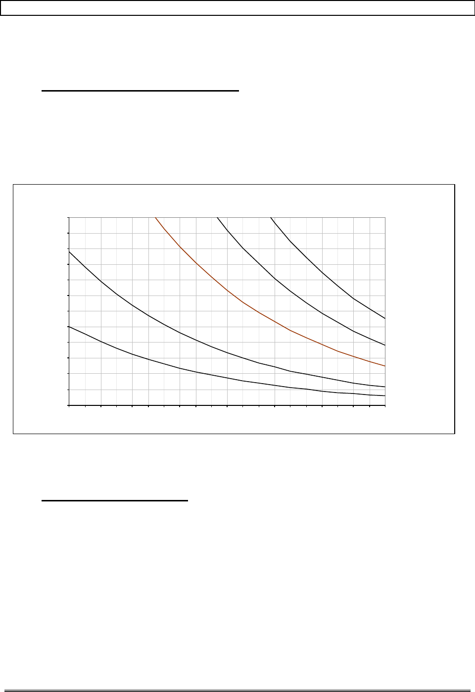
TransCell 1900TM System Installation & Integration Manual 1000462 A
Page 44
TRANSCEPT PROPRIETARY - DATA ON THIS PAGE SUBJECT TO RESTRICTIONS CITED ON COVER AND TITLE
Appendix A:
Data Link Antenna Installation Options
A-1 ANTENNA SELECTION AND SPACING
The information given in the main body of this document pertains to a 2-foot parabolic dish
with tower separation of 6 and 12 miles. To give more flexibility and solutions to various
installation issues, Figure A-1 depicts datalink coverage given antenna size and tower
position.
The cable used for all the calculations is Andrew type LDF4.5. This is the largest diameter
cable that can be used at 5.8 GHz.
Figure A-1 Datalink Coverage (20dB margin)
A-2 DATA LINK INTERFERENCE
In some service areas, issues may arise with regards to other non-licensed users in the area
interfering with the data link. Depending on the interference source and what access you
have to the other source; interference problems can be solved in the following ways:
♦ If you have a working relationship with the other user of the spread spectrum
unlicensed band, you can work with that user to adjust which channel you both
transmit and receive on.
♦ If you do not have a working relationship with the other user of the spread spectrum
unlicensed band, the interference problem can be solved by:
1) Adjusting the data link channels away from the other user.
2) Using the opposite antenna polarization.
Antenna Selection Guide
(20 dB Link Margin)
0.00
1.00
2.00
3.00
4.00
5.00
6.00
7.00
8.00
9.00
10.00
11.00
12.00
100 110 120 130 140 150 160 170 180 190 200 210 220 230 240 250 260 270 280 290 300
Antenna Heigth Above Ground (Feet)
Range (Miles)
2' Antenna Coverage Region
3' Antenna Coverage Region
4' Antenna Coverage Region
5' Antenna
Coverage Region
(If Available)
6' Antenna
Coverage Region
(If Available)

TransCell 1900TM System Installation & Integration Manual 1000462 A
Page 45
TRANSCEPT PROPRIETARY - DATA ON THIS PAGE SUBJECT TO RESTRICTIONS CITED ON COVER AND TITLE
3) Increasing the size of the parabolic dish used. This gives a tighter beam width
that is less susceptible to interference.

TRANSCEPT PROPRIETARY
TRANSCEPT PROPRIETARY
Appendix B:
Sample Installation Data Sheets
Site Name: Date:
System Configuration:
HUB SPM SN: Remote SPM SN:
HTM SN: RTM SN:
DLM SN: DLM SN:
Tx Primary Sector 1-3 TDMA Ch. EVM 1 Peak EVM 1 Avg. EVM 10 Signal Level (dBm)
1
2
Tx Diversity Sector 1-3
3
4
5
6
Forward RF Test Measurements

TRANSCEPT PROPRIETARY
TRANSCEPT PROPRIETARY
Site Name:
Date:
System Configuration:
HUB
SPM SN:
Remote
SPM SN:
HTM SN: RTM SN:
DLM SN: DLM SN:
Rx Primary Sector 1 TDMA Ch. EVM 1 Peak EVM 1 Avg. EVM 10 Signal Level (dBm)
1
2
3
4
5
6
Rx Primary Sector 2
1
2
3
4
5
6
Rx Primary Sector 3
1
2
3
4
5
6
Rx Diversity Sector 1
1
2
3
4
5
6
Rx Diversity Sector 2
1
2
3
4
5
6
Rx Diversity Sector 3
1
2
3
4
5
6
Reverse RF Test Measurements
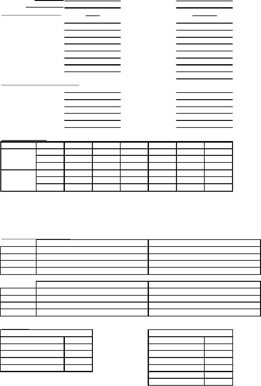
TRANSCEPT PROPRIETARY
TRANSCEPT PROPRIETARY
System Configuration:
SPM1 SN:
SPM1 SN:
SPM2 SN:
SPM2 SN:
HTM1 SN:
RTM1 SN:
HTM2 SN:
RTM2 SN:
DLM1 SN:
DLM1 SN:
DLM2 SN:
DLM2 SN:
LVPS1 SN:
LVPS1 SN:
LVPS2 SN:
LVPS2 SN:
TTA SN:
TDMA Channel Assignments:
Carrier 1
Carrier 2
Carrier 3
Carrier 4
Carrier 5
Carrier 6
System Settings:
Ch. 1
Ch. 2
Ch. 3
Ch. 4
Ch. 5
Ch. 6
FWGain
HUBSPM
PRVAtten
DRVAtten
FWAtten
REMSPM
PRVGain
DRVGain
IP Network Configuration:
HUB
IPAddress
Subnet Mask
Default GW
Hostname
REM
IPAddress
Subnet Mask
Default GW
Hostname
Data Link:
Input Power dBm
Frequency (2.4/5.8)
5.8 Ghz
Vertical Rx Power dBm Hub Tx Channel
Horizontal Rx Power dBm Hub Rx Channel
Path Loss dB Rem Tx Channel
Link Margin dB Rem Rx Channel
Hub Forward Atten
Rem Forward Atten
HUB Remote
Site Name:
Enclosure SN:
SPM2
SPM1
SPM2
Alignment:
Configuration:
SPM1
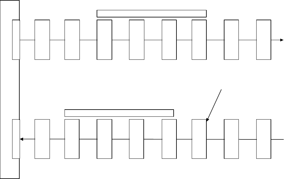
TRANSCEPT PROPRIETARY
TRANSCEPT PROPRIETARY
Appendix C:
HRP Power Level Limits
BTS
Pad
(G=-54)
Pads +
internal
cable
loss
HTM
Fwd
(G=+2)
A/D
(G=0)
max
=
+7dBm
DDC
max
=
+14dBm
DUC
G=
-(Atten
+2)
D/A
(G=-13)
relative
to A/D
max
=
-2dBm
RTM
Fwd
(G=18)
PA
(G=49)
HTM
Rev
(G=-22)
D/A
(G=-13)
relative
to A/D
max
=
-2dBm
DUC
G=
-(atten+
2)
DDC
(gain=12)
max
=
+14dBm
A/D
(G=0)
max
=
+7dBm
RTM
Rev
(G=19)
LNA
w/
combiner
and cable
(G=18)
TMA
w/
cable
and
Remote
internal
losses
(G=7)
+40dBm
-25dBm +3dBm -6dBm -19dBm -1dBm +48dBm
-50dBm-39dBm -17dBm -4dBm +6dBm -6dBm -6dBm -25dBm -43dBm
TransCell 1900TM Power Plan
Digital section
Digital section
-110dBm-99dBm -77dBm -64dBm -54dBm -66dBm -66dBm -85dBm -103dBm
-39dBm+5dBm +5dBm -14dBm -32dBm
+30dBm
-15dBm
Atten=12 dB
-23dBm
-13dBm
-23dBm
-13dBm
Gain =
16 to 26 dB Atten =1-13 dB
(nominally 7dB) Noatten
control
Atten= 6 dBAtten = 4 dB
(set to 10 dB if only
1 signal in a given
half band(hi/
lo))
Atten =8 dB
(set to 2 dB if only
1 signal in a given
half band(hi/
lo))
3dB
cable
loss
-42 dBm
-102 dBm
Test tone injected at
-33dBm equivalent input
1dB
cable
loss

TRANSCEPT PROPRIETARY
TRANSCEPT PROPRIETARY
TransCell 1900TM
SEM/HUI
User's Guide
Document No. 1000483
Revision A
February 22, 2001
THIS DOCUMENT CONTAINS PROPRIETARY INFORMATION OF TRANSCEPT, INC. AND IS
TO BE USED ONLY IN ACCORDANCE WITH THE NONDISCLOSURE AGREEMENT UNDER
WHICH THIS DOCUMENT IS PROVIDED. THIS DOCUMENT IS NOT TO BE DUPLICATED IN
WHOLE OR IN PART WITHOUT PRIOR WRITTEN PERMISSION FROM A DULY AUTHORIZED
REPRESENTATIVE OF TRANSCEPT, INC.
THE REVISION STATUS OF ALL PAGES IN THIS DOCUMENT IS THE SAME AS THAT
STATED ON THIS COVER.

TRANSCEPT PROPRIETARY
TRANSCEPT PROPRIETARY
DRAWING NO. 1000483
DOCUMENT CHANGE HISTORY
DATE REV DESCRIPTION APPD
02/22/01 AReleased to ECO control per RN010221 km/CL
Copyright 1999 - 2001 Transcept, Inc.
All rights reserved.

TransCell 1900TM SEM/HUI User’s Guide Document No. 1000483 A
Page i
TRANSCEPT PROPRIETARY - DATA ON THIS PAGE SUBJECT TO RESTRICTIONS CITED ON COVER AND TITLE
TABLE OF CONTENTS
Section Page
1. INTRODUCTION.......................................................................................................................1
1.1 NOTATION CONVENTIONS .......................................................................................................1
1.2 ACRONYMS AND ABBREVIATIONS.............................................................................................2
1.3 REFERENCE DOCUMENTATION .................................................................................................2
1.4 SYSTEM OVERVIEW.................................................................................................................2
1.4.1 Network Requirements..................................................................................................2
1.4.2 Hub/Remote Pair Configuration.....................................................................................5
1.4.3 HRP Hostname..............................................................................................................5
2. SYSTEM ELEMENT MANAGER (SEM) SOFTWARE............................................................7
2.1 OVERVIEW..............................................................................................................................7
2.2 SEM WINDOWS......................................................................................................................7
2.2.1 Network Config Window................................................................................................7
2.2.1.1 SEM Tree Structure................................................................................................8
2.2.1.2 Active Alarms Tab..................................................................................................8
2.2.2 Logged Alarms Tab .......................................................................................................9
2.2.3 IP Config Window........................................................................................................10
2.2.4 System Config Window................................................................................................12
2.3 SEM POWER-ON/POWER-OFF ..........................................................................................13
2.3.1 SEM Workstation Power-On Procedure......................................................................13
2.3.2 SEM Workstation Power-off Procedure.......................................................................14
3. HRP USER INTERFACE (HUI) SOFTWARE........................................................................15
3.1 HUI WINDOWS......................................................................................................................15
3.1.1 Main Window................................................................................................................15
3.1.2 HRP Login Dialog ........................................................................................................16
3.1.3 IP List Editor Option.....................................................................................................16
4. SEM/HUI INSTALLAT ION .....................................................................................................18
4.1 JAVA RUNTIME ENVIRONMENT (JRE) INSTALLATION..............................................................18
4.2 HUI SOFTWARE INSTALLATION..............................................................................................18
4.3 SEM SOFTWARE INSTALLATION ............................................................................................19
4.3.1 SEM Application Software Installation.........................................................................19
4.3.2 SEM Database Software Installation...........................................................................19
4.3.3 SEM Database Setup..................................................................................................20
4.3.4 Autologin of SEM software ..........................................................................................22
5. SEM OPERATION..................................................................................................................25
5.1 SEM.....................................................................................................................................25
5.1.1 Launching SEM Software............................................................................................25
5.1.2 Closing SEM Software.................................................................................................25
5.1.3 Remote Access of the SEM ........................................................................................25
5.1.4 Setting up the SEM workstation as a Host..................................................................25
5.1.4.1 Adding a Host Session.........................................................................................25
5.1.5 Establishing New Caller Parameters...........................................................................29
5.1.6 Logging into the SEM from a remote Workstation......................................................32
6. HUI OPERATION ...................................................................................................................34
6.1 HUI.......................................................................................................................................34
6.1.1 Launching HUI Software..............................................................................................34

TransCell 1900TM SEM/HUI User’s Guide Document No. 1000483 A
Page ii
TRANSCEPT PROPRIETARY - DATA ON THIS PAGE SUBJECT TO RESTRICTIONS CITED ON COVER AND TITLE
6.1.2 Logging In via HUI.......................................................................................................34
6.1.3 Logging Out..................................................................................................................34
6.1.4 Closing HUI Software...................................................................................................34
6.1.5 Portable Computer IP Address Change Procedure (For Local HUI Use)..................35
6.1.5.1 Setting Computer TCP/IP Configuration..............................................................35
6.1.5.2 Restore Computer TCP/IP Configuration............................................................39
6.1.6 HUI Script Files............................................................................................................40
7. COMMAND LINE INTERFACE (CLI) ....................................................................................41
7.1 HRP COMMAND LANGUAGE OVERVIEW.................................................................................41
7.2 COMMANDS ..........................................................................................................................42
7.2.1 SET Message..............................................................................................................42
7.2.2 GET Message..............................................................................................................45
7.2.3 RESET Message.........................................................................................................50
7.2.4 LOGIN Message..........................................................................................................51
7.2.5 LOGOUT Message......................................................................................................51
7.2.6 CLOSE Message.........................................................................................................51
7.2.7 WRITE Message..........................................................................................................52
LIST OF ILLUSTRATIONS
Figure Page
FIGURE 1-1. TYPICAL TRANSCELL 1900TM SYSTEM CONFIGURATION IN A WIRELESS NETWORK.......3
FIGURE 1-2. HRP INTERCOMMUNICATIONS........................................................................................5
FIGURE 2-1. NETWORK CONFIGURATION WINDOW (ACTIVE ALARMS TAB)..........................................8
FIGURE 2-2. NETWORK CONFIGURATION WINDOW (LOGGED ALARMS TAB)......................................10
FIGURE 2-3. IP CONFIGURATION WINDOW.......................................................................................11
FIGURE 2-4. SYSTEM CONFIGURATION WINDOW..............................................................................13
FIGURE 3-1. HUI WINDOW...............................................................................................................16
FIGURE 3-2. HUI LOGIN DIALOG......................................................................................................16
FIGURE 3-3. HUI IP LIST EDITOR DIALOG ........................................................................................17
FIGURE 5-1. PCANYWHERE “BE A HOST PC” GUI............................................................................26
FIGURE 5-2. NAMING THE HOST PC SESSION ..................................................................................26
FIGURE 5-3. CONNECTION DEVICE GUI...........................................................................................27
FIGURE 5-4. SECURITY LEVEL GUI..................................................................................................27
FIGURE 5-5. SUCCESSFUL COMPLETION GUI...................................................................................28
FIGURE 5-6. NEW SESSION ICON APPEARS......................................................................................29
FIGURE 5-7. CALLERS TAB IN PROPERTIES GUI...............................................................................30
FIGURE 5-8. CALLER NAME ENTRY ..................................................................................................30
FIGURE 5-9. LOGIN NAME AND PASSWORD ENTRY...........................................................................31
FIGURE 5-10. SUCCESSFUL COMPLETION GUI.................................................................................31
FIGURE 5-11. SEM PHONE NUMBER ENTRY....................................................................................32
FIGURE 5-12. REMOTE LOGIN GUI...................................................................................................33
FIGURE 5-13. REMOTE SEM SESSION .............................................................................................33
FIGURE 6-1. NETWORK NEIGHBORHOOD POP-UP.............................................................................36
FIGURE 6-2. NETWORK DIALOG .......................................................................................................36
FIGURE 6-3. NETWORK PROTOCOLS SELECTION WINDOW...............................................................37
FIGURE 6-4. MICROSOFT TCP/IP PROPERTIES DIALOG ...................................................................37
FIGURE 6-5. MICROSOFT TCP/IP PROPERTIES DIALOG – DNS TAB ................................................38
FIGURE 6-6. MICROSOFT TCP/IP PROPERTIES DIALOG – WINS ADDRESS TAB...............................39

TransCell 1900TM SEM/HUI User’s Guide Document No. 1000483 A
Page iii
TRANSCEPT PROPRIETARY - DATA ON THIS PAGE SUBJECT TO RESTRICTIONS CITED ON COVER AND TITLE
LIST OF TABLES
Table Page
TABLE 1-1. HUB CELL 1 V.35 INTERFACE ..........................................................................................4
TABLE 1-2. HRP HOSTNAME CONVENTION ........................................................................................6
TABLE 6-1. HUI SCRIPTS.................................................................................................................40
TABLE 7-1. CLI SET COMMANDS .....................................................................................................43
TABLE 7-2. CLI GET COMMANDS .....................................................................................................46
TABLE 7-3. CLI RESET COMMANDS .................................................................................................50

TransCell 1900TM SEM/HUI User’s Guide Document No. 1000483 A
Page 1
TRANSCEPT PROPRIETARY - DATA ON THIS PAGE SUBJECT TO RESTRICTIONS CITED ON COVER AND TITLE
1. INTRODUCTION
This manual is the User’s Guide for the SEM and HUI Subsystems of the TransCell
1900TM System. The manual is organized into the following sections:
Section 1 – General TransCell 1900TM networking information.
Section 2 – Users guide for SEM.
Section 3 – Users guide for HUI.
Section 4 – Installation procedure for the SEM/HUI software.
Section 5 – Operating procedure for the SEM software.
Section 6 – Operating procedure for the HUI software.
Section 7 – Command Line Interface definition
1.1 NOTATION CONVENTIONS
This manual assumes that the user has a basic knowledge of the Windows NT
operating system. Several typographic conventions and standard Windows NT terms
are used in this manual when discussing the HRP user interface software. They are as
follows:
Mouse Commands - The HRP user interface software uses only the left mouse button:
“click” - press and release the left mouse button
“double-click” - press and release left mouse button twice in quick succession
Menu Commands - Menu commands are bolded with each command level separated
from the previous one by a slash (/) mark, e.g., “Select Privileges/Modify Privileges.”
Button Names – Command button names in dialogs are underlined, e.g., “To exit from
dialog, click Close.”
Key Names - Key names are spelled out and appear in small, bold capital letters, e.g.
ENTER, ESCAPE, CONTROL.
Dialogs and Messages - Dialog and message titles are generally referenced exactly as
they are shown on the title bar. However, version numbers appearing in the title bar are
usually not referenced, so a dialog title that actually reads “SEM (Version 1.2)” is
referred to as the SEM dialog.
Dialog Options - Labels for dialog options (text boxes, radio buttons, and drop-down
lists) are shown in italics, e.g., “Select desired IP Address.” All instructions to “select” or
“choose” an option imply clicking on that option (options can be selected via the
keyboard as well).
Keyboard Input - Instructions for keyboard entries start with “Type: ...”, and anything that
should be typed in verbatim is shown in a contrasting font. For example, “Type: set hub
fwdatten 2 12.5 in the HRP Command: text box.”
Displayed Text - Text displayed in a dialog box is shown in another contrasting font, e.g.,
“The HRP Response dialog displays the message CONFIRM: SET HUB FWDATTEN 2
12.5.

TransCell 1900TM SEM/HUI User’s Guide Document No. 1000483 A
Page 2
TRANSCEPT PROPRIETARY - DATA ON THIS PAGE SUBJECT TO RESTRICTIONS CITED ON COVER AND TITLE
1.2 ACRONYMS AND ABBREVIATIONS
GUI Graphical User Interface
HRP Hub Remote Pair
HUI HRP User Interface
SPM Signal Processing Module
SEM System Element Manager
6CMR 6 Carrier Microwave Repeater (TransCell 1900TM)
CLI Command Line Interface
HTM Hub Transceiver Module
RTM Remote Transceiver Module
DLM Datalink Module
LVPS Low Voltage Power Supply
OSS Operation Support System
1.3 REFERENCE DOCUMENTATION
• TransCell 1900TM System Operation and Maintenance Manual, Transcept Document
No. 1000497
1.4 SYSTEM OVERVIEW
1.4.1 Network Requirements
Figure 1-1 shows a typical configuration for the TransCell 1900TM System.
The System Element Manager (SEM) and Host User Interface (HUI) communicate with a
Hub/Remote Pair (HRP) over the customer’s WAN. The HRPs are connected to a
customer provided CSU/DSU via a V.35 serial connection. The CSU/DSU
communicates over a DS0 slot in a T1 line to another CSU/DSU at the customer’s
switch. The CSU/DSU at the switch is connected to a router over another V.35 serial
connection.
A IP network connection can now be established between the Transcept V.35 Master
SPM in the HRP and the Customer’s Router at the switch. Once this connection has
been established, the SEM can connect to the HRP to monitor its health. Likewise a
HUI located on the customer’s network can connect to the HRP to view or change
system settings. The Router must be programmed to pass traffic for the HRP IPs out of
its V.35 serial port that is connected to the CSU/DSU.
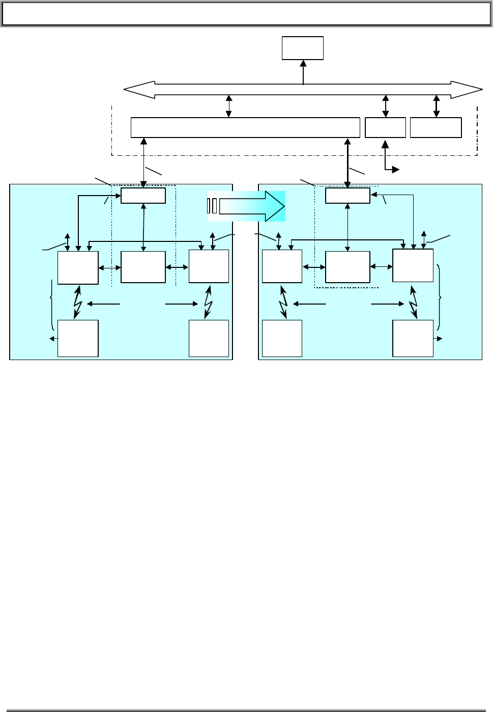
TransCell 1900TM SEM/HUI User’s Guide Document No. 1000483 A
Page 3
TRANSCEPT PROPRIETARY - DATA ON THIS PAGE SUBJECT TO RESTRICTIONS CITED ON COVER AND TITLE
POTS Line
(for remote monitoring
via pcAnywhere)
Local
Access
10BaseT
&
RS-232
BTS
3 Sector
CSU/DSU
Microwave Link
V.35
DS0
MSC
T1 T1
DS0Extraction
Customer Wide Area Network
OSS
Hub-Remote
Pair (HRP)
Combined Alarm Data
SEM HRP
User Interface
Local
Access
10BaseT
&
RS-232
Remote 2
Serial
Cell 2
Hub
Cell 1
Hub
Remote 1
BTS
CSU/DSU
Microwave Link
Local
Access
10BaseT
&
RS-232
Local
Access
10BaseT
&
RS-232
Remote 1
Cell 1
Hub
Cell 2
Hub
Remote 2
V.35
DS0
SCCS SCCS
Local
Access
10BaseT
&
RS-232
Serial
Node 1
Node N
Note: Cell 2
is Optional Note: Cell 2
is Optional
Figure 1-1. Typical TransCell 1900TM System Configuration in a Wireless Network
To operate a Transcept SEM and HUI over a network, the customer must provide the
following items:
• IP address for SEM (one per switch)
• Ethernet drop for SEM (to connect to customer’s WAN)
• POTS line for SEM (allows dial-in access via pcAnywhere)
• CSU/DSU at Hub site
• DS0 extraction at SEM site
• Two IP addresses for each HRP in system (one for each Hub, one for each
Remote)
• The IP address of the serial interface of the Router at the switch which is
assigned to the HRP
• Verification of the Circuit Optioning/Conditioning, e.g. 64Kbps throughout ppp
link, external clocking from DSU/CSU to SPM, etc.
• The cable that connects the CSU/DSU at the Cell Site to the Transcept Hub
25-pin D female connector (See Table-1 below). Note: This connector pinout
matches the ADC Kentrox DataSMART T1 25-pin D. If this type of
CSU/DSU is used a “straight-through” 25 pin D male-to- male cable will work.

TransCell 1900TM SEM/HUI User’s Guide Document No. 1000483 A
Page 4
TRANSCEPT PROPRIETARY - DATA ON THIS PAGE SUBJECT TO RESTRICTIONS CITED ON COVER AND TITLE
Table 1-1. Hub Cell 1 V.35 Interface
Pin # Signal Name
1. PROTECTIVE GND
2. XMT DATA (A)
3. RCV DATA (A)
4. REQUEST TO SEND
5. CLEAR TO SEND
6. N/C
7. SIGNAL GND
8. CARRIER DETECT
9. RCV CLK (B)
10. N/C
11. N/C
12. XMT CLK (B)
13. N/C
14. XMT DATA (B)
15. XMT CLK (A)
16. RCV DATA (B)
17. RCV CLK (A)
18. N/C
19. N/C
20. DATA TERM READY
21. N/C
22. N/C
23. N/C
24. N/C
25. N/C
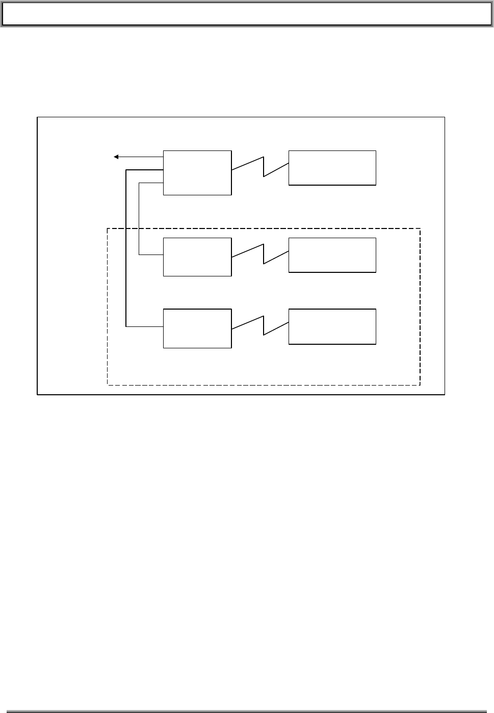
TransCell 1900TM SEM/HUI User’s Guide Document No. 1000483 A
Page 5
TRANSCEPT PROPRIETARY - DATA ON THIS PAGE SUBJECT TO RESTRICTIONS CITED ON COVER AND TITLE
1.4.2 Hub/Remote Pair Configuration
A tower site can support up to three HRPs as shown in the following figure.
Figure 1-2. HRP Intercommunications
The Cell 1 Hub contains the V.35 interface and acts as the gateway into the customer’s
network for all other HRPs in the node. All Hubs communicate with their Remotes via
Point-to-Point protocol (PPP) across the microwave datalink. The Cell 2 and Cell 3 Hub
communicate with the Cell 1 Hub via PPP across a serial CAT5 cable.
The customer supplied IP addresses for the HRP SPMs must be entered into the
network configuration file in each respective SPM. In addition, the IP address of the
serail port of the router at the switch must be entered into the network configuration file
of the Cell 1 Hub SPM. Once configured, the SPMs will automatically setup the network
routing for SEM and HUI access each time they are powered up or reset.
1.4.3 HRP Hostname
Each HRP has two hostnames, one for the HUB and one for the REMOTE. The SPM
hostname is used by system software to create valid routing tables throughout the
TransCell 1900TM system. See the following for an example:
m.h.c1.node1.6cmr.id0.customer.com
This hostname contains several fields which pinpoint its corresponding SPM within the
Transcell 1900TM system as follows:
HUB SPM
CELL 1
V.35 Master
REMOTE SPM
CELL 1
Microwave Datalink
HUB SPM
CELL 2 REMOTE SPM
CELL 2
Microwave Datalink
HUB SPM
CELL 3 REMOTE SPM
CELL 3
Microwave Datalink
V.35
Interface
CELL2 & CELL3 Optional
PPP Serial
Interface
PPP Serial
Interface
To customer’s
DSU/CSU

TransCell 1900TM SEM/HUI User’s Guide Document No. 1000483 A
Page 6
TRANSCEPT PROPRIETARY - DATA ON THIS PAGE SUBJECT TO RESTRICTIONS CITED ON COVER AND TITLE
Table 1-2. HRP Hostname Convention
Field Description Valid values
“m” Designates the “Master” SPM in a 12 carrier
system. All 6 carrier system hostnames begin
with m
12CMR: m,s
6CMR: m
“h” Designates the “HUB” SPM of the Hub / Remote
pair. “h”: HUB
“r”: REMOTE
“c1” “Cell One”. A “Dual HUB” configuration supports
two complete HRPs with one v.35 back-haul.
“Cell One” is the HRP with the physical v.35
connection. “Cell two” is the second HRP, which
has a PPP TTY connection to “Cell One” through
a serial CAT5 cable.
“c1” : v.35 routing
“c2” : Co-located second HRP
with serial PPP to “c1”.
“node1” First node of several on a site list. A TransCell
1900TM “node” in this context is any site location
where one or more HUB units are located.
User defined,
no “special” characters or
spaces.
“6cmr” Transcept product designator 6cmr
“id0” Optional HRP designator User defined,
no “special” characters or
spaces.
“customer.com” Customer domain ID User Defined

TransCell 1900TM SEM/HUI User’s Guide Document No. 1000483 A
Page 7
TRANSCEPT PROPRIETARY - DATA ON THIS PAGE SUBJECT TO RESTRICTIONS CITED ON COVER AND TITLE
2. SYSTEM ELEMENT MANAGER (SEM) SOFTWARE
2.1 OVERVIEW
This section describes the operation of the SEM application. The menus and dialogs are
displayed in Microsoft Windows NT format.
The SEM software application, installed in a SEM workstation, has the following features
and capabilities:
• Automatically connects to all HRPs in the network for monitoring of alarm data
• Communicates with each HRP by connecting to the Ethernet network via a network
interface card
• Provides remote user access via pcANYWHERE.
• Monitors HRP heartbeat
• Monitors and reports HRP communications alarms
• Maintains HRP time synchronization
• Records alarms (active and logged)
• Allows local display of alarms (active and logged)
• Manages alarms in alarm database
• Allows external HUI access into alarm database
• Combined alarm port that combines all alarms into single ASCII output stream
• Provides network access to the combined alarm port
• Simultaneous remote access via combined alarm port by as many as 10 multiple
users
• Password-controlled access
• Uses a watchdog interface to force a system reset in the case of SEM software failure
• Provides GUI mechanism for closing alarms that are not auto-closable
• Provides GUI for allowing administrator to modify network parameters
• Provides GUI for allowing the HRP identifiers to be updated
• Automatically updates the HRP identifiers throughout the network
2.2 SEM WINDOWS
2.2.1 Network Config Window
The Network Config tab selects the Network Configuration Window. The Network Config
GUI contains the SEM tree folder structure as well as the Active and Logged Alarms
tabs.
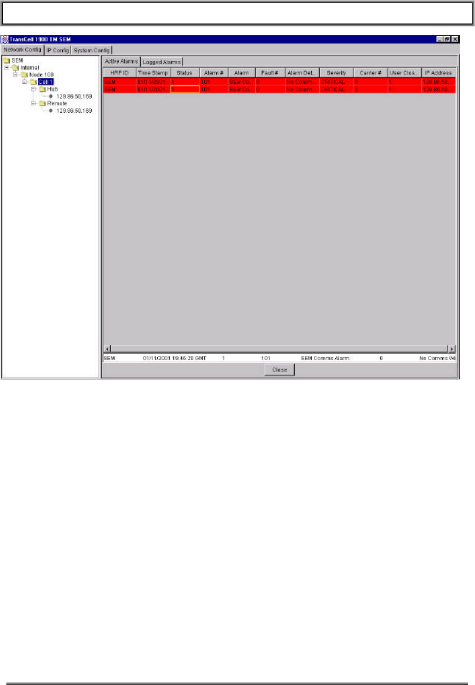
TransCell 1900TM SEM/HUI User’s Guide Document No. 1000483 A
Page 8
TRANSCEPT PROPRIETARY - DATA ON THIS PAGE SUBJECT TO RESTRICTIONS CITED ON COVER AND TITLE
Figure 2-1. Network Configuration Window (Active Alarms Tab)
2.2.1.1 SEM Tree Structure
The SEM tree structure to the left of the screen can be extended by double clicking on
the folder icons. By choosing one of the branches you can more narrowly view the
alarms from selected HRPs
The SEM tree expandable folders allow you to view the configuration setup.
2.2.1.2 Active Alarms Tab
The Active Alarms tab, shown in Figure 2-1, displays the alarms that are currently active.
The SEM tree structure to the left of the Active Alarms Tab can be used to view alarms
for a particular Hub or Remote. In the Active Alarm display are the following items:
• Close Alarm Selection Field – This field is found at the bottom of the Active Alarm
display. An alarm must be selected in order to close (click on open alarm). The
selected alarm is displayed in the Close Alarm Selection Field (initially invisible).
• Close Button – At bottom of Active Alarm display. Closes selected alarm.
• HRP ID – HRP ID of the HRP generating alarm
• Time Stamp – Time alarm occurred (GMT).

TransCell 1900TM SEM/HUI User’s Guide Document No. 1000483 A
Page 9
TRANSCEPT PROPRIETARY - DATA ON THIS PAGE SUBJECT TO RESTRICTIONS CITED ON COVER AND TITLE
• Status – Alarm status (1=open, 0=closed).
• Alarm # -- Alarm reference number.
• Alarm – Alarm name.
• Fault # -- Number of fault causing alarm.
• Alarm Details – Detailed description of alarm.
• Severity – Severity of the alarm (can also be recognized by color)
• Carrier # -- Carrier number(1-6) affected by alarm (non-applicable if = 0)
• User Closeable – Indicates whether or not User can close this alarm (1=Yes, 0 =No)
• IP Address – IP address of HRP generating alarm
The “column table headers” allow sorting of the alarms. For example, clicking on the
Time Stamp header will sort the alarms according to the time that the alarm occurred.
The applies to all “column table headers”. Both the Active Alarms tab and the Logged
Alarms tab (see next section) have this feature.
2.2.2 Logged Alarms Tab
The Logged Alarms tab, shown in Figure 2-2, is very similar to the Active Alarms tab. It
displays all of the same column table headers but replaces the Close Alarm Selection
Field and Close button with three new buttons:
• Prev – Allows user to view previous 500 logged alarms
• Next – Allows user to view the next 500 logged alarms
• Refresh – Lists the most current logged alarms
The Display Area displays the last 500 alarms in chronological order. If there are more
alarms than can be viewed in a window, a scroll bar appears on the right hand side of
the display.
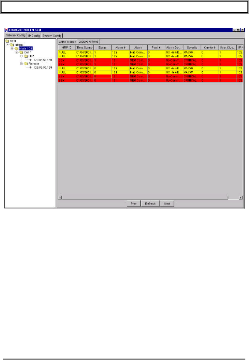
TransCell 1900TM SEM/HUI User’s Guide Document No. 1000483 A
Page 10
TRANSCEPT PROPRIETARY - DATA ON THIS PAGE SUBJECT TO RESTRICTIONS CITED ON COVER AND TITLE
Figure 2-2. Network Configuration Window (Logged Alarms Tab)
2.2.3 IP Config Window
The IP Config tab is used to display the IP configuration window (Figure 2-3). The IP
configuration window is used to enter the IP addresses for an HRP.
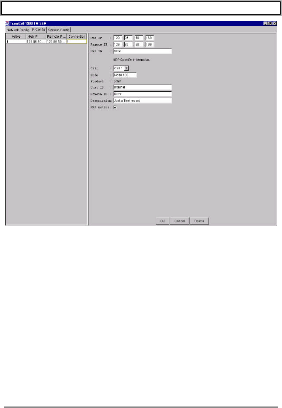
TransCell 1900TM SEM/HUI User’s Guide Document No. 1000483 A
Page 11
TRANSCEPT PROPRIETARY - DATA ON THIS PAGE SUBJECT TO RESTRICTIONS CITED ON COVER AND TITLE
Figure 2-3. IP Configuration Window
The list area on the left side of the Window displays all HRPs that have been entered into the IP
Address List. The column table headers in the list are as follows:
• Active – Indicates if the HRP is currently active (1=Active, 0=Inactive). If Active the
SEM will monitor the HRP.
• Hub IP – The IP address for the Hub.
• Remote IP – The IP address for the Remote.
• Connection – Indicates if an HRP is connected (1=Yes, 0=No).
The right side of the IP Config Window provides a means to add HRP IP addresses and
information. The fields and buttons are as follows.
• Hub IP – Enter the IP Address for the Hub
• Remote IP – Enter the IP Address for the Remote
• HRP ID – Enter the ID of selected HRP
• Cell Pulldown – Each cell represents a HRP (cells 1, 2 or 3)
• Node – A node identifies a set of up to three HRPs.
• Product Code – The field is fixed at 6cmr (6 Carrier Microwave Repeater)

TransCell 1900TM SEM/HUI User’s Guide Document No. 1000483 A
Page 12
TRANSCEPT PROPRIETARY - DATA ON THIS PAGE SUBJECT TO RESTRICTIONS CITED ON COVER AND TITLE
• Customer ID – Corresponds to id0 in the hostname (see section 1.4.3). This customer
selected field can be used for the Hub’s site name or whatever unique identifier is
desired.
• Domain ID – Corresponds to customer.com in the hostname (see section 1.4.3). This
customer selected field can be used to identify the customer’s network domain.
• Description – User configurable description. This can be used to describe the address
or location of the Hub equipment.
• HRP Active checkbox – Check this box if the selected HRP is installed and operational.
The SEM will not attempt to contact this HRP until this box has been checked.
• OK Button – Adds the new information to the IP address list
• Cancel Button – Clears the information in the entry area
• Delete Button – Deletes the entry from the IP address list
Note: The data entered in these fields must correspond to the hostname and IP address
data configured at an HRP. See section 1.4.3.
Note: Since the SEM generates its own alarms, the SEM’s IP address must be added to the IP Config
list as both a Hub and a Remote, and be marked as Inactive. If this is not done, the SEM generated
alarms will not show up as active alarms, nor will they be logged to the database.
2.2.4 System Config Window
The System configuration window, shown in Figure 2-4, allows the user to view the
constants currently set in place as well as change those constants to desired levels.
♦ Display_Thread_Time_Millis – Period in milliseconds between screen refreshes.
(min=500, max=10000, default=1000)
♦ Hub_Response_Timeout_Secs – Period in seconds the SEM waits for a response
from the Hub. (min=10, max=60, default=30)
♦ Alarm_Port_Number – The NOCC combined alarm port (min=0, max=65535,
default=4000)
♦ Hub_Time_Tolerance_Secs – Period in seconds SEM allows SPM time variance
(min=30, max=300, default=30)
♦ Hub_Heartbeat_Period_Secs – Period in seconds SEM waits for a heartbeat before
setting a Hub comms alarm for that HRP (min=60, max=900, default=120)
♦ Watchdog_Timeout_Secs – Period to wait before updating watchdog card (min=30,
max=300, default=60)
♦ Current value column – The current value column displays the current settings for
the various constants listed.
♦ Desired value column – The desired value column allows you to either enter desired
values for reference purposes or enter newly desired values. After you enter the
newly desired value in a given column you can press the OK Button to make the
desired value the actual value.
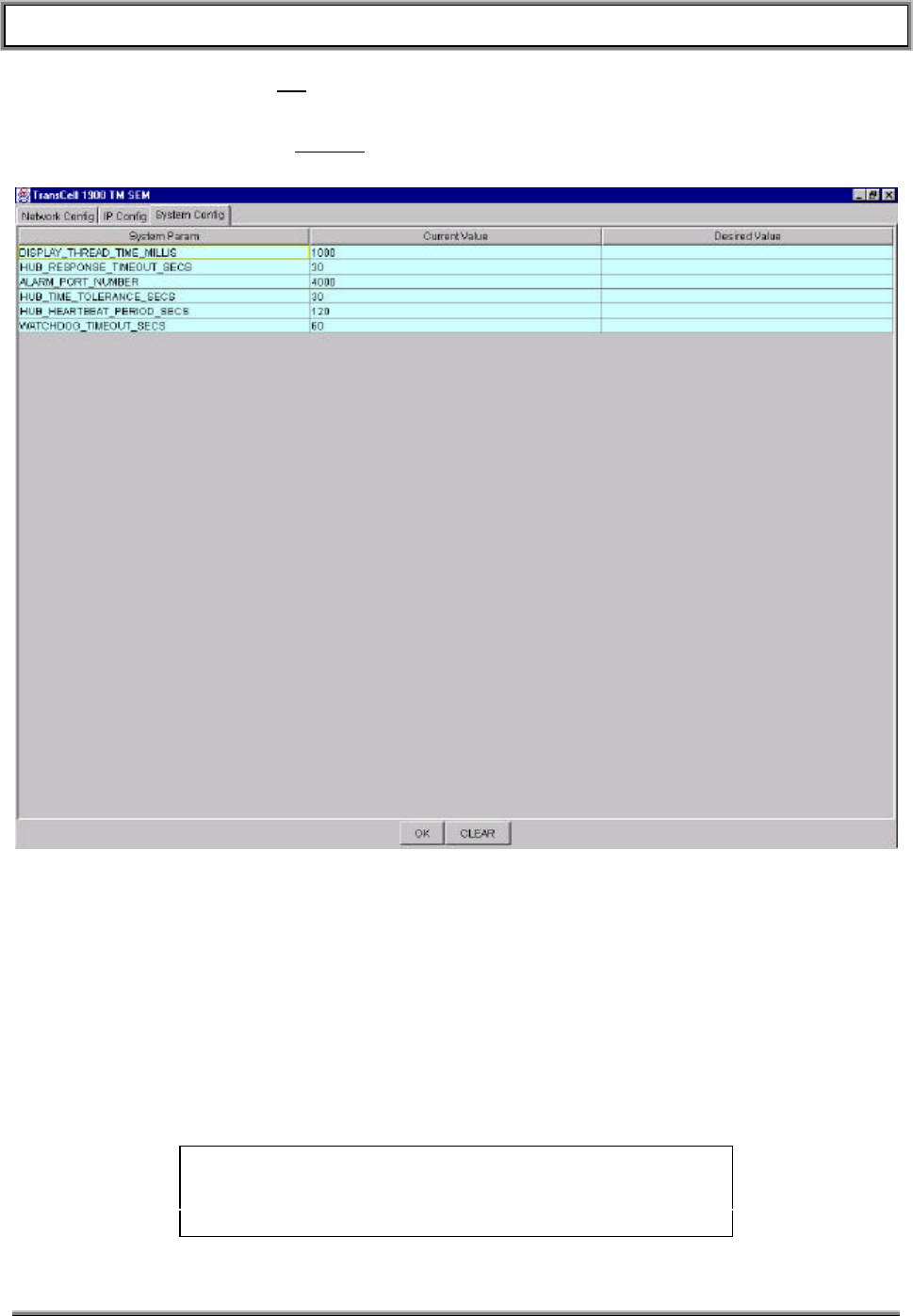
TransCell 1900TM SEM/HUI User’s Guide Document No. 1000483 A
Page 13
TRANSCEPT PROPRIETARY - DATA ON THIS PAGE SUBJECT TO RESTRICTIONS CITED ON COVER AND TITLE
♦ OK Button – The OK Button causes data entered in the desired value column to
replace the data currently in the current value column.
♦ Clear Button – The CLEAR Button will clear out all of the values listed in the desired
value column.
Figure 2-4. System Configuration Window
2.3 SEM POWER-ON/POWER-OFF
The SEM workstation is typically installed at the Master Switch Center (MSC). It is
recommended that you use a UPS or a surge suppressor to protect the SEM workstation
against AC power fluctuations.
2.3.1 SEM Workstation Power-On Procedure
• Ensure that SEM workstation and monitor are connected to an AC power source.
• Set monitor power ON/OFF switch to ON. Observe that power indicator lights.
NOTE
If the monitor power cable is connected to the computer, the
monitor will not turn on until the computer is powered up.
• Set SEM computer power ON/OFF switch to ON. Observe that power indicator lights.
TransCell 1900TM SEM/HUI User’s Guide Document No. 1000483 A
Page 14
TRANSCEPT PROPRIETARY - DATA ON THIS PAGE SUBJECT TO RESTRICTIONS CITED ON COVER AND TITLE
• After SEM workstation executes boot-up routine, Windows NT Desktop is displayed.
• The SEM software will automatically load and its Network Configuration window will
display.
• If you are setting up the SEM because of a system error or failure it is recommended
that you re-install the database software prior to setting up the SEM.
2.3.2 SEM Workstation Power-off Procedure
NOTE
The SEM workstation normally operates 24 hours a day,
seven days a week. A system shutdown is only required
when a SEM workstation is to be replaced or new
software loaded. Shut down SEM workstation operating
software per instructions in paragraph 5.1.2.
• Shutdown Windows NT operating system software by selecting the Start button on
the Windows NT task bar (bottom left), and then selecting Shut Down….
• At Shut Down Windows dialog, select Shut down the computer? then click Yes.
• Wait for Windows NT operating system message prompt saying that it is OK to
shut off computer, then set SEM workstation power switch to OFF. Observe that
power indicator goes out.
• Set monitor power switch to OFF. Observe that power indicator goes out.
NOTE
If the monitor power cable is connected to the computer, the
monitor will be shut down when the computer is powered off.

TransCell 1900TM SEM/HUI User’s Guide Document No. 1000483 A
Page 15
TRANSCEPT PROPRIETARY - DATA ON THIS PAGE SUBJECT TO RESTRICTIONS CITED ON COVER AND TITLE
3. HRP USER INTERFACE (HUI) SOFTWARE
3.1 HUI WINDOWS
The HUI is used to communicate with the SPM software in the HRPs. It is shown in
Figure 3-1. It consists of a Main Window, a login dialog and a IP List editor.
3.1.1 Main Window
The parts comprising the Main HUI Window are as follows:
• IP Address – Provides a scrollable list of valid IP addresses of all SPMs in TransCell
1900TM System
• HRP ID – The customized identity of each HRP IP address
• Status – Indicates the current status of the communications link; connected or not
connected
• Gender – Indicates whether this SPM is a Hub or a Remote
• HRP Command – Text entry location for CLI commands to be sent to the HRP
• HRP Response – Displays all commands entered in the HRP Command box, responses
to those commands, and any errors that may have occurred. HRP Responses and the
heading REPORT are shown in Blue type.Menu Bar – Contains pull-down menus
• File Menu – Allows a user to exit the HUI
• Edit Menu – Allows the use access to the edit IP edit option to add or delete IP
addresses to and from the IP Addresses list box. (Only functional when a user is not
yet logged into the system.)
• View Menu – Allows you to view the Log File where commands and their responses
are stored
• Options Menu – Future.
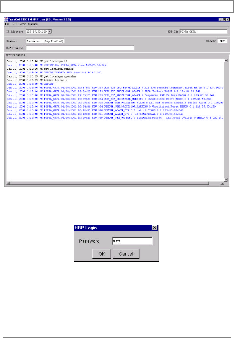
TransCell 1900TM SEM/HUI User’s Guide Document No. 1000483 A
Page 16
TRANSCEPT PROPRIETARY - DATA ON THIS PAGE SUBJECT TO RESTRICTIONS CITED ON COVER AND TITLE
Figure 3-1. HUI Window
3.1.2 HRP Login Dialog
The HRP Login dialog is used to for entering a password. A typical HRP Login dialog is shown
in Figure 3-2. Enter the selected HRP’s password to connect to the HRP.
Figure 3-2. HUI Login Dialog
3.1.3 IP List Editor Option
The IP Addresses option allows the user to add and delete IP addresses from the
ipaddresses.txt file without having to open that file for direct editing. This option can only
be used if the HUI is not connected to an HRP. Once you input a new IP or delete an
existing IP, the IP Addresses box on the HUI will be updated to reflect changes.
• OK Button – The OK Button will add the new IP entered in the text fields and it will also
close the “IP List Editor”.
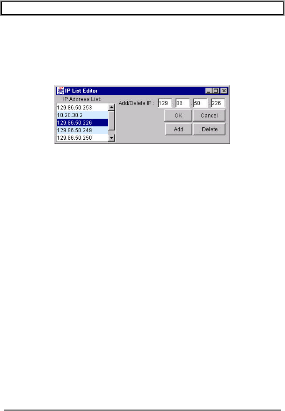
TransCell 1900TM SEM/HUI User’s Guide Document No. 1000483 A
Page 17
TRANSCEPT PROPRIETARY - DATA ON THIS PAGE SUBJECT TO RESTRICTIONS CITED ON COVER AND TITLE
• Cancel Button – The Cancel Button will terminate the “IP List Editor” window ignoring
any data in the IP text field.
• Add Button – The Add Button will add the new IP entered in the text fields and leave the
Editor open for more changes to take place.
• Delete Button – The Delete Button will remove the selected IP from the ipaddresses.txt
file and from all other lists and boxes containing the selected address. You can either
type the IP into the text fields or more simply click on the desired IP in the adjacent list.
Figure 3-3. HUI IP List Editor Dialog

TransCell 1900TM SEM/HUI User’s Guide Document No. 1000483 A
Page 18
TRANSCEPT PROPRIETARY - DATA ON THIS PAGE SUBJECT TO RESTRICTIONS CITED ON COVER AND TITLE
4. SEM/HUI INSTALLATION
Both applications are installed in the computer designated as the SEM workstation. The
HUI software may be installed in any other suitably configured Windows NT computer as
well. The following procedures are provided for performing common tasks with respect to
SEM/HUI software.
CAUTION
Use the SEM application on the SEM workstation only.
Simultaneous use of the SEM application by two or more
computers connected to the same TDMA network will cause
these applications to constantly contend for control and thereby
render the alarm monitoring function inoperative.
4.1 JAVA RUNTIME ENVIRONMENT (JRE) INSTALLATION
Both the SEM and HUI applications are written in Java. In order for these applications to
run, they require that Sun Microsystems’ Java Runtime Environment (JRE) software be
loaded. The JRE is preloaded on the SEM workstation. Instructions are provided here
in case the software should become corrupted, or if a JRE software upgrade should
become necessary.
a. Insert the CD-ROM provided by Transcept labeled “Java Runtime Environment” into
the CD-ROM drive.
b. Using NT explorer, click on the file jre1_2_2-001-win.exe.
c. An installation program will guide you through the installation process.
d. Accept the license agreement.
e. Accept the default destination folder: C:\Program Files\JavaSoft\JRE\1.2.
f. The JRE will install and the installation program will exit automatically upon
installation completion.
4.2 HUI SOFTWARE INSTALLATION
The HUI software is installed as follows:
• Insert the floppy labeled “HRP User Interface (HUI)” into A:\ drive. The floppy
contains a self-extracting archive file that will auto-extract the files into the correct
directory structure.
• Using NT explorer, select the A:\ drive and double click on the .exe file. Accept the
default directory structure.
• Click on the Unzip button. After the unzip process is complete two directories should
have been created: config and dev_hui. Click on the Close button.
• If this a new install, you will need to create a shortcut pointing to the following:
• C:\dev_HUI\classes\com\Transcept\tdma\HRPUser.bat.

TransCell 1900TM SEM/HUI User’s Guide Document No. 1000483 A
Page 19
TRANSCEPT PROPRIETARY - DATA ON THIS PAGE SUBJECT TO RESTRICTIONS CITED ON COVER AND TITLE
4.3 SEM SOFTWARE INSTALLATION
4.3.1 SEM Application Software Installation
The SEM software is provided by Transcept on a CD-ROM. If this is a first time install,
you will have to set the CLASSPATH variables in order to run the class files.
• Setting the CLASSPATH variables
• To set the CLASSPATH, right click on MyComputer.
• Choose properties from the pulldown.
• Click on the Environment tab.
• Type: CLASSPATH in the Variable text field.
• In the Value text field type: .;c:\dev\mysql.jar;%CLASSPATH%. The
CLASSPATH lets the computer know where to look for java files associated with
the program that is running. In this instance we are telling it to look under
c:\dev\mysql.jar. It is VERY important that the classpath be typed correctly. It
puts the starting directory in the classpath.
• Click the Set button then click OK.
• Insert the CD-ROM labeled “SYSTEM ELEMENT MANAGER” into the CD-ROM
drive.
• Using NT Explorer, select the CD-ROM drive. There should be a folder labeled dev
on the CD.
• Click and drag the folder labeled dev from the CD-ROM onto the [C:]
• If this a new install, you will need to create shortcuts pointing to the following batch
files: C:\dev\SEM.bat, C:\dev\Watchdog.bat, and C:\dev\DatabaseBackup.bat.
• If this a new install, you will also need to put the c:\dev directory on the SEM
workstation’s path. To do this you must have administrator privileges. Right click on
My Computer and select Properties. Select the environment tab. In the System
Variables area find and select path. In the Value box hit the right arrow key to go to
the end of the line. Then type: ;c:\dev and hit the Set button. Then hit the Apply
button followed by the OK button.
4.3.2 SEM Database Software Installation
The SEM software uses a MySQL database to store and process alarm data. Therefore
the MySQL database must be installed prior to using the SEM.
The SEM workstation comes ready with the database installed. If for some reason you
need to reinstall the database follow the instructions below.
• Insert the CD-ROM labeled “MYSQL DATABASE” into the CD-ROM drive.
• Using NT Explorer, select the CD-ROM drive.
• Double click on the MySQLselfExtract.exe file. The contents will be put into
D:\programs\mysql\bin by default if you choose not to specify a different drive. Select
the disk drive that has the most free space on it. Click on the Unzip button.
• Click on the Close button.

TransCell 1900TM SEM/HUI User’s Guide Document No. 1000483 A
Page 20
TRANSCEPT PROPRIETARY - DATA ON THIS PAGE SUBJECT TO RESTRICTIONS CITED ON COVER AND TITLE
• Select the disk that you had the files unzipped to. Navigate to the
\programs\mysql\bin directory.
• Click on Setup.exe to install the database.
• An installer window will open up to guide you through the MySQL installation.
• Click Next for the first two windows. On the window titled “Choose Destination
Location” c:\mysql will be the path already in the box. Do not accept this default.
• Click on the button labeled Browse.
• At the bottom of the display there is a pull-down menu labeled drives:. Click on it
and select the drive that has the most free space. The letter drive you selected will
appear in the path text area above.
• After the letter drive you chose, type: mysql. It should read as <drive letter>:\mysql
• Press OK and click Next.
• Choose a typical installation. Now press OK.
4.3.3 SEM Database Setup
There are a few simple steps to follow when setting up the database. Special care
needs to be taken to type SQL statements exactly as seen in the steps to follow. SQL is
case sensitive when it comes to database and table names.
• Open up a command window by clicking on the start menu and selecting the option
labeled Run. Type cmd in the text field and press enter.
• To get to the proper root directory (the directory where you chose to install MySQL)
type <letter>: where letter would be the letter of the drive where MySQL is installed.
• Now specify the path by typing: cd \mysql\bin
• At the prompt type: mysql–nt –install
• Next type: net start mysql
• For initial login to the database simply type: mysql –u root at the prompt.
• Note: Later you will login differently by typing something like the following at the
prompt: mysql --user=semuser --password=passwordHere
• Once you have the prompt that looks like mysql> type: use mysql
• Typing the above statement will give the root user access to the mysql database.
There is no password for the root user initially.
Setting a Password For the Root User
Once you are logged into MySQL you can perform various tasks among which is
changing passwords. Primarily you may want to set a password for the ‘root’
user. The syntax for doing this follows:
mysql> UPDATE user SET password=PASSWORD(‘new_password’) WHERE
user=’root’;
If you do not change the password promptly, there is a risk of non-authorized
access to the database.

TransCell 1900TM SEM/HUI User’s Guide Document No. 1000483 A
Page 21
TRANSCEPT PROPRIETARY - DATA ON THIS PAGE SUBJECT TO RESTRICTIONS CITED ON COVER AND TITLE
User Levels in MySQL Explained
There are mainly two user levels in MySQL: administrator and user. If you log
on as root you are using the administrator level. As an administrator you can
create new users and give those users certain restricted privileges. As an
administrator you can also give a user administrative privileges. Generally you
do not want to give a user administrative privileges because they could
inadvertently delete tables or the entire database.
For the SEM operations, the only privileges you need be concerned about are
update, delete, insert and select. These are the privileges that should be given
to any new users you allocate. You may want to GRANT all privileges to a user if
that user is going to be you. Doing such is unnecessary but you may wish to log
in under a username you more commonly use instead of ‘root’. The syntax for
granting all privileges to a user is:
GRANT ALL PRIVILEGES ON *.* TO ‘some username here’ IDENTIFIED BY
‘some_password’ WITH GRANT OPTION;
Giving Database Privileges to the New User
The privileges that we are going to give are the only privileges necessary for the
semuser to get all of the desired information from the database
Type: GRANT update,delete,insert,select ON *.* TO semuser@”%” identified by
‘livefreeordie’;
Type: GRANT update,delete,insert,select ON *.* TO semuser@localhost
identified by ‘livefreeordie’;
Type the above statements exactly. Make sure to include the single quotes
around the password livefreeordie. Once you have done this you have created a
valid user for the database.
Creating the SEMDB
At the mysql> prompt type: CREATE database SEMDB;
You have now created the SEM database shell. Remember that if you want to
access the SEMDB you must type the database name in all capitals just as you
created it.
In order to access any information in the newly created database type: use
SEMDB
Creating and Initializing the Tables
A script file has been previously written and is stored on the SEM machine d:
drive.
At the mysql> prompt type: \. <drive letter>:\sqlscripts\mainsqlscript.sql
To verify that the tables were created type: show tables;
You should see a list of eight tables that were created from the script file.
To verify that the tables were initialized type: select * from systemcontrol; You
should see some values. This indicates that the tables were initialized from the

TransCell 1900TM SEM/HUI User’s Guide Document No. 1000483 A
Page 22
TRANSCEPT PROPRIETARY - DATA ON THIS PAGE SUBJECT TO RESTRICTIONS CITED ON COVER AND TITLE
sql Script file. A separate script file exists for all of the tables if you wish to
recreate only one or two of the tables.
Everything should be set up properly at this point. To exit from the database
type: quit at the prompt.
Repairing Corrupted Database
If for some reason the database has been corrupted there are a four procedural
steps to follow in order to restore it to full operational status:
• Restore systemcontrol table in SEMDB.
• Reset dbinsertion
• Drop openalarm and closedalarm tables from the database.
• Recreate the openalarm and closedalarm tables.
The easiest way to perform all of these tasks is to “drop” the four tables
mentioned above and then run the script file that was used to create the tables:
• Login to MySQL using the root user and password. (See Section 3.3.2)
• At the mysql prompt type: use SEMDB
• To drop the tables type: drop table openalarm, closedalarm, dbinsertion,
systemcontrol;
Note:
Do not drop the dbinsertion table without dropping the openalarms
and closedalarms tables first.
• Type: show tables; to verify that the tables have been dropped.
• In order to restore the tables, type: \. <drive
letter>:\sqlscripts\mainsqlscript.sql
The tables that were dropped should be restored and the database should be
repaired.
Manually Resetting closedalarm, openalarm and dbinsertion Tables
The process for resetting the tables is the same as described in previously.
4.3.4 Autologin of SEM software
The SEM workstation should be set up so that the SEM software loads automatically
upon power up. No login GUI will appear. Login as SEMUser will happen automatically.
This is done through the Microsoft applications TweakUI and AutoExNT. Autologin
setup instructions are provided here in case the hard disk has crashed or has become
corrupted. You will need administrator privileges to do this installation.
Obtaining and Installing TweakUI and AutoExNT
• Insert the SEM Workstation Drivers CD-ROM and use NT explorer to select the
TweakUI directory. (As an alternative you can download the program from URL:
http://www.microsoft.com/Windows95/downloads/contents/WUToys/W95PwrToysSet/Default.as
p)

TransCell 1900TM SEM/HUI User’s Guide Document No. 1000483 A
Page 23
TRANSCEPT PROPRIETARY - DATA ON THIS PAGE SUBJECT TO RESTRICTIONS CITED ON COVER AND TITLE
• Copy or download the software to Desktop. If you are working off of the SEM CD
there is no TweakUI.exe file. The purpose of this file is to unzip the others, however
they are provided already unzipped on the CD. Skip ahead to where you find
tweakui.inf.
• On your Desktop double click on the TweakUI.exe icon.
• Extract the files to: C:/TweakUI.
• Using WindowsNT Explorer explore your C:\ drive.
• Double click on the folder labeled TweakUI (where the files unzipped to).
• You should see four files. Right click on the file labeled tweakui.inf.
• Click Install on the menu that appears. TweakUI is now installed on your computer.
Close the Help window that appears by clicking the X in the upper right hand corner
of the window.
• Use NT explorer and select the AutoExNT directory on the CD-ROM. (As an
alternative you can download the files from
http://www.cs.ucc.ie/downloads/NT/autoexnt/.) Copy the files Autoexnt.exe,
Instexnt.exe, Servemess.dll, and Autoexnt.bat to the C:\WINNT\system32
directory.
• Open up a command prompt and go to C:\WINNT\system32 by typing:
C:
cd C:WINNT\system32
• At the prompt type INSTEXNT install. The AutoExNT program will be installed.
Close the command prompt window.
Setting Up the Auto LogIn Feature
This procedure will show how to set up TweakUI to automatically login as SEMUser with
password semuser and automatically launch the SEM software.
• To set up auto logon double click on My Computer.
• Double click on Control Panel.
• Find the TweakUI icon and double click on it. A window will appear.
• There are several tabs at the top of the window. Click on the tab labeled Logon.
• You will see two text fields. One of them should contain your user name. Change
the username to read SEMUser. In the other text field type in the password currently
used for SEMUser logon. The password upon delivery is semuser. It is possible
that the password has been changed since delivery of the SEM.
• Put a check in the box labeled “Log on automatically at system startup”. Do this by
clicking the mouse in the box.
• Click the OK Button.
• Open up Control Panel and click on Services.
• Under services click on AutoExNT and click the Startup button.
• Under Startup Type check Automatic and click OK.

TransCell 1900TM SEM/HUI User’s Guide Document No. 1000483 A
Page 24
TRANSCEPT PROPRIETARY - DATA ON THIS PAGE SUBJECT TO RESTRICTIONS CITED ON COVER AND TITLE
• Log off from the current session by selecting Start/Shut Down, selecting “Close all
programs and log on as a different user” and click the Yes button. You should login
automatically and the SEM software should launch.
Disabling the Auto LogIn Feature
In order to be able to login as a different user (such as administrator) you will need to
disable the autologin feature. The simplest way to do this is to change the password to
SEMUser so the autologin feature fails.
• Type the ctl-alt-del key sequence.
• Click on the Change Password button in the Windows NT Security GUI.
• In the Change Password GUI type in the Old Password: semuser, the New
Password: test, and Confirm New Password: test. Click on the OK button.
• A message will pop up indicating your password has been changed. Click the OK
button.
• Click the Cancel button on the Windows NT security GUI to return to your session.
• Log off of the current session as explained in the section above. When the system
tries to login as SEMUser it will fail because the password has changed. You may
now select a different Login name and password, or type in the new password, test,
to login as SEM User.
When you have finished your task requiring the different login name, be sure to log back
in as SEMUser and change the password back to semuser so that if power is lost, the
SEM workstation will autologin and bring back the SEM software. NOTE: To
permanently disable autologin you must log in as Administrator and disable the autologin
service from the Control Panel Services. There should be no need to do this.

TransCell 1900TM SEM/HUI User’s Guide Document No. 1000483 A
Page 25
TRANSCEPT PROPRIETARY - DATA ON THIS PAGE SUBJECT TO RESTRICTIONS CITED ON COVER AND TITLE
5. SEM OPERATION
5.1 SEM
5.1.1 Launching SEM Software
The SEM software should have launched automatically at startup. The SEM software
consists of the SEM GUI application and a Watchdog timer application. The Watchdog
timer converses with the SEM application to ensure that the SEM application is
operational. If the SEM application should crash, the Watchdog application will reboot the
SEM workstation.
Both of these applications should have launched at startup. If autologin has been
disabled, or if you have closed the SEM software and wish to reopen it, double-click on
the SEM icon on the desktop to launch the SEM application. Then double-click on the
Watchdog icon on the desktop to launch the Watchdog timer application.
Once the SEM software is operating the user should enter the IP addresses and specific
node information for each HRP in the network (see section 2.2.2). Once the HRPs have
been entered, the SEM software will automatically contact each HRP and log alarm
information as necessary. Most alarms are closed automatically when the cause has
been corrected. There are some User-closeable alarms. See the OAM manual for alarm
descriptions.
5.1.2 Closing SEM Software
The SEM application has a 24/7 runtime and should be shut down only for administrative
maintenance. To initiate the SEM software shutdown routine, select EXIT in the FILE pull-
down menu at the upper left corner of the SEM application window. The EXIT command
will disable the SEM hardware watchdog timer and close the SEM workstation software
without generating a SEM Unsolicited Reset Alarm.
CAUTION
Failure to exit the SEM workstation software properly may result
in problems with software the next time the software is
initialized.
5.1.3 Remote Access of the SEM
The SEM workstation is supplied with Symantec’s pcAnywhere software to provide a
means to access the SEM remotely. The workstation must be connected to a POTS line
to provide dial in access.
5.1.4 Setting up the SEM workstation as a Host
Before a remote SEM session can be established, the SEM workstation must be
configured to accept the call over its 56K modem. To do this you must first add the host
session then set up new caller parameters.
5.1.4.1 Adding a Host Session
a. Click on the Symantec pcAnywhere icon, or select Start/Programs/Symantec
pcAnywhere.
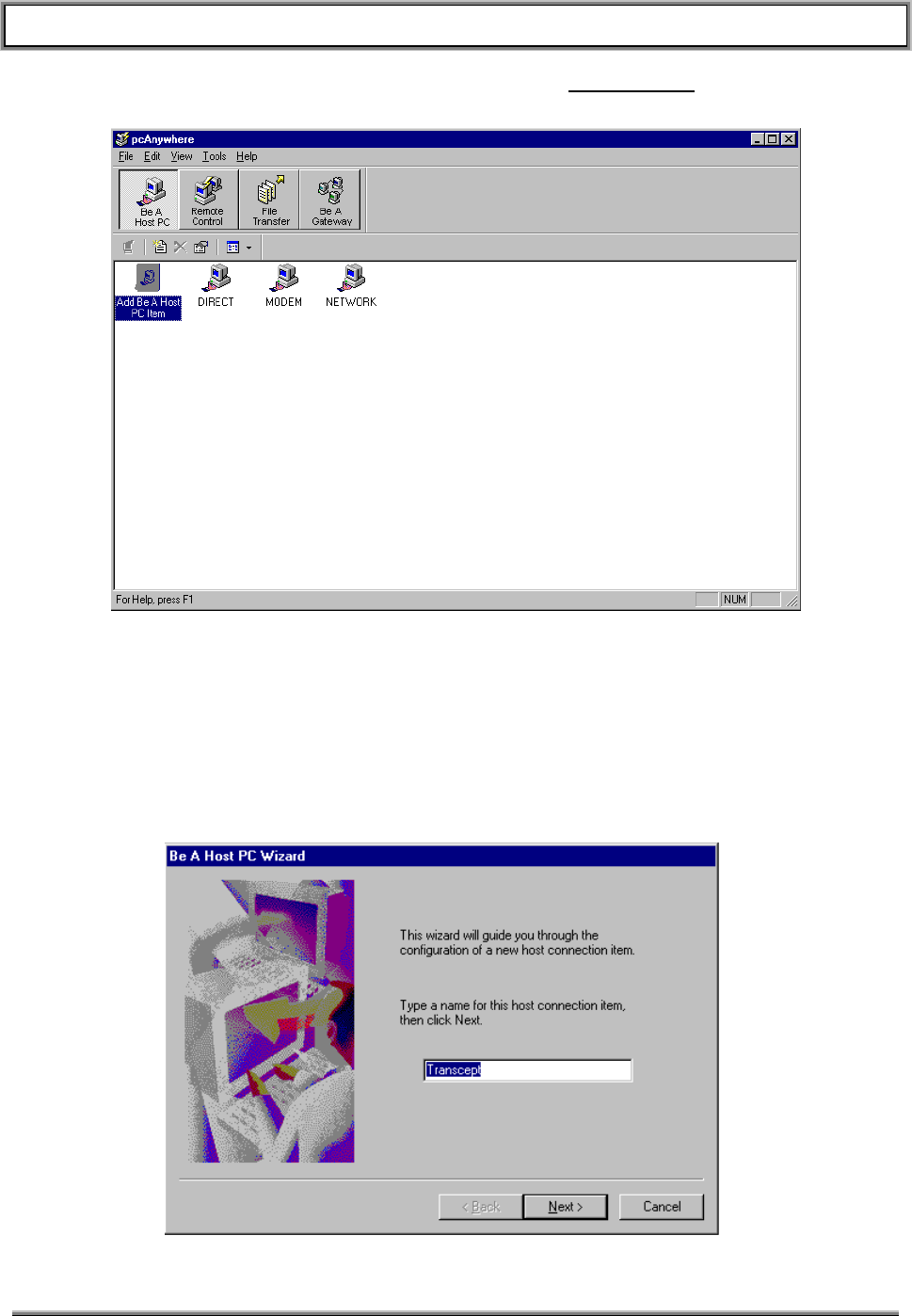
TransCell 1900TM SEM/HUI User’s Guide Document No. 1000483 A
Page 26
TRANSCEPT PROPRIETARY - DATA ON THIS PAGE SUBJECT TO RESTRICTIONS CITED ON COVER AND TITLE
b. When the pcAnywhere GUI appears, click on the Be a Host PC button as shown in
Figure 5-1.
Figure 5-1. pcAnywhere “Be a Host PC” GUI
c. Double-click on the “Add Be A Host PC Item”. A series of GUIs will appear to walk
you through the Add process. Figure 5-2 shows the first of these GUIs. Enter the
name of the session. This example names the session “Transcept”. This name will
appear beneath a new PC icon in the “Be a Host PC” GUI when you are done with
the Add process.
Figure 5-2. Naming the Host PC Session
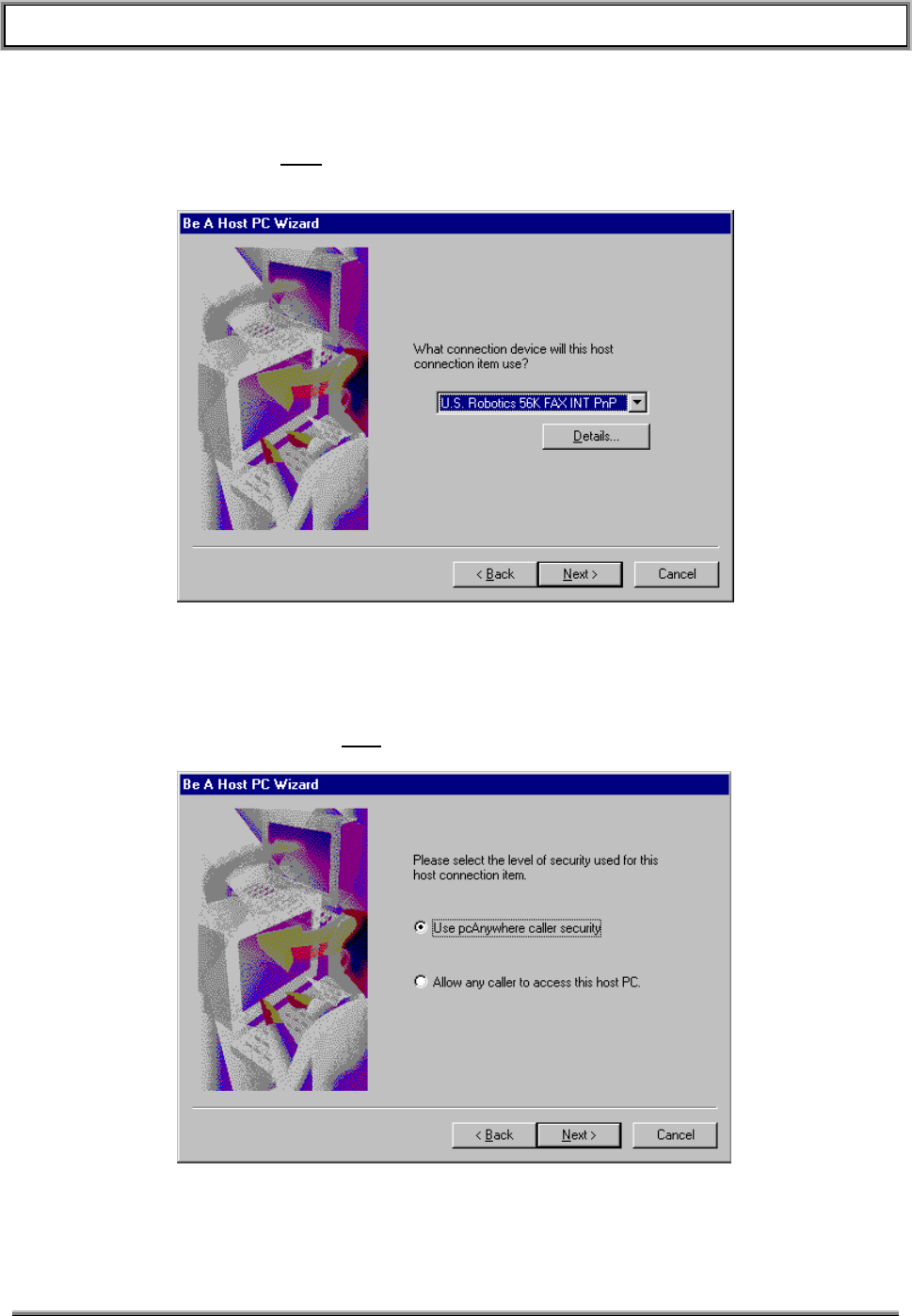
TransCell 1900TM SEM/HUI User’s Guide Document No. 1000483 A
Page 27
TRANSCEPT PROPRIETARY - DATA ON THIS PAGE SUBJECT TO RESTRICTIONS CITED ON COVER AND TITLE
d. Click the Next button to bring up the connection device GUI (Figure 5-3). The
modem installed in the SEM workstation should be highlighted. Accept this default
by clicking on the Next button.
Figure 5-3. Connection Device GUI
e. The Security Level GUI will appear (Figure 5-4). Accept the default to use
pcAnywhere calling security. We will setup the security parameters later in this
procedure. Click on the Next button.
Figure 5-4. Security Level GUI
If you have never before set up a Host PC session on this workstation, pcAnywhere will
automatically take you into the “Add Caller” wizard. If this happens, jump ahead to
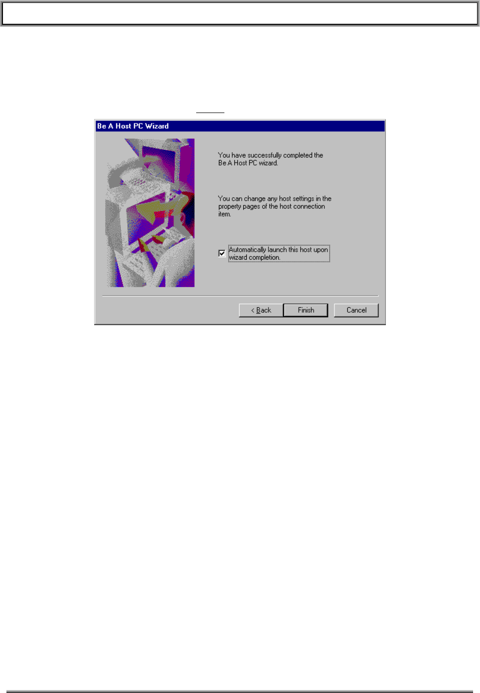
TransCell 1900TM SEM/HUI User’s Guide Document No. 1000483 A
Page 28
TRANSCEPT PROPRIETARY - DATA ON THIS PAGE SUBJECT TO RESTRICTIONS CITED ON COVER AND TITLE
section 5.1.5 step c. and follow instructions from there. Upon completion of the “Add
Caller” you will be returned to the “Successful Completion” GUI shown in Figure 5-5. If
you have set up a Host PC session previously, you will proceed immediately to the
“Successful Completion” GUI. The default checkbox selecting “Automatically launch this
host upon wizard completion” will default to on. Uncheck this box by clicking on the
check mark. Then Click on the Finish button.
Figure 5-5. Successful Completion GUI
f. When the Successful Completion GUI clears, the session just created should appear
as an icon in the Be a Host PC GUI as shown in Figure 5-6.
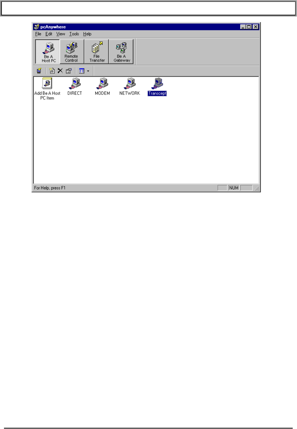
TransCell 1900TM SEM/HUI User’s Guide Document No. 1000483 A
Page 29
TRANSCEPT PROPRIETARY - DATA ON THIS PAGE SUBJECT TO RESTRICTIONS CITED ON COVER AND TITLE
Figure 5-6. New Session Icon Appears
5.1.5 Establishing New Caller Parameters
a. In the Be a Host GUI, right click on the session icon you created in the last section.
Select the properties item from the pop-up menu. When the Properties GUI appears
select the “Callers” tab as shown in Figure 5-7.
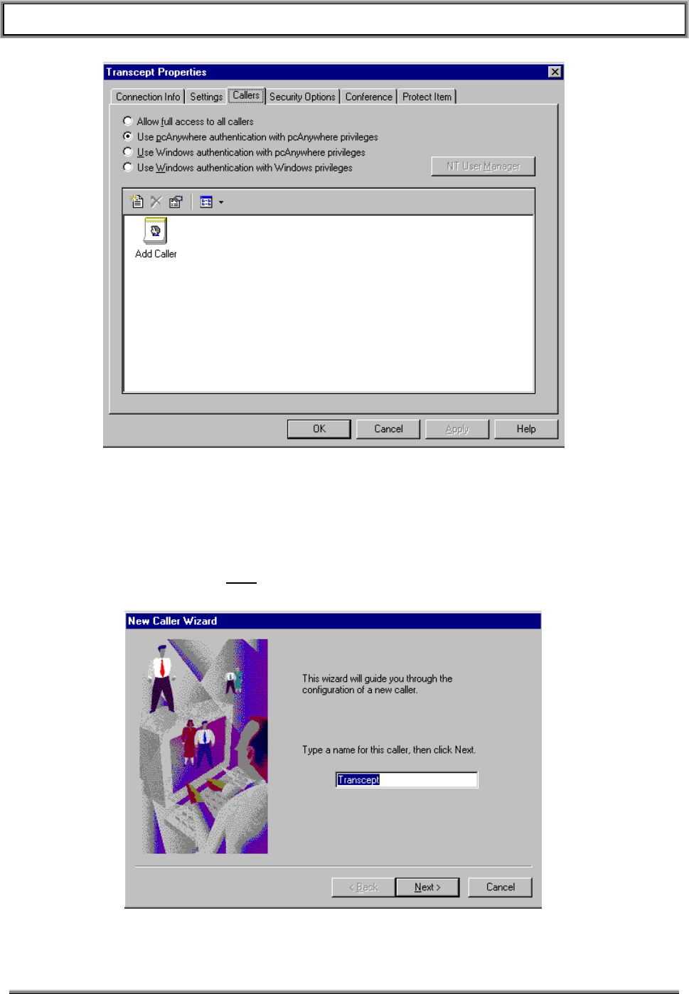
TransCell 1900TM SEM/HUI User’s Guide Document No. 1000483 A
Page 30
TRANSCEPT PROPRIETARY - DATA ON THIS PAGE SUBJECT TO RESTRICTIONS CITED ON COVER AND TITLE
Figure 5-7. Callers Tab in Properties GUI
b. Double click on the Add Caller icon to launch the New Caller Wizard (Figure 5-8).
c. Enter the Caller name. In this example we have entered “Transcept” as the caller
name. Click on the Next button to proceed.
Figure 5-8. Caller Name Entry
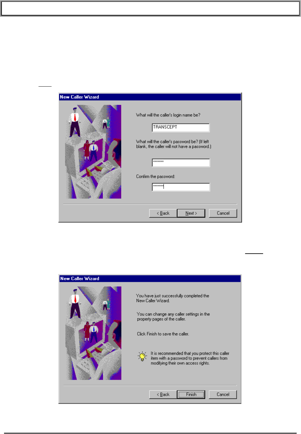
TransCell 1900TM SEM/HUI User’s Guide Document No. 1000483 A
Page 31
TRANSCEPT PROPRIETARY - DATA ON THIS PAGE SUBJECT TO RESTRICTIONS CITED ON COVER AND TITLE
d. The next GUI allows entry of the remote user’s login name and password. These will
be entered at the remote workstation in order to establish a pcAnywhere connection
with the Host PC (the SEM workstation). Enter the remote login name and
password. The example in Figure 5-9 uses the login name of “Transcept” and
password of “semuser”. Both the login name and password are not case sensitive.
The password will be blanked by asterisks as you enter it. Once finished, click the
Next button.
Figure 5-9. Login Name and Password Entry
e. The Successful Completion GUI (Figure 5-10) will appear. Click the Finish button to
close the Add Caller Wizard.
Figure 5-10. Successful Completion GUI
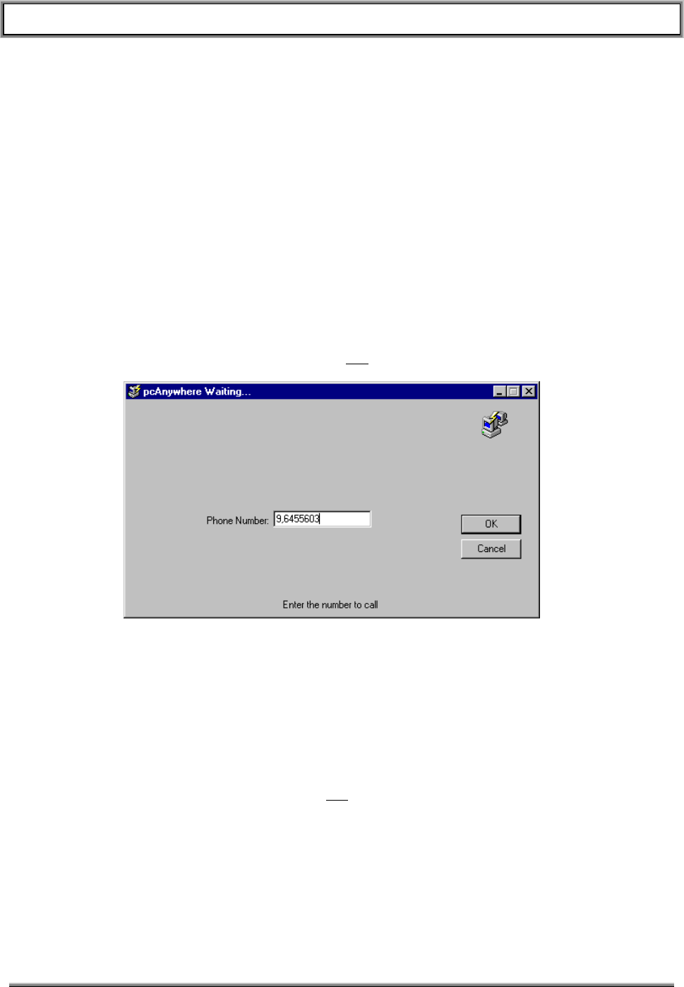
TransCell 1900TM SEM/HUI User’s Guide Document No. 1000483 A
Page 32
TRANSCEPT PROPRIETARY - DATA ON THIS PAGE SUBJECT TO RESTRICTIONS CITED ON COVER AND TITLE
f. You have now created a Host PC session that will allow a user to login to the SEM
workstation using a login name and password. To activate the session, i.e. to set the
SEM PC to expect an incoming caller, double click on the session icon. The
pcAnywhere “Be a Host PC GUI” will disappear. The SEM workstation will now
accept a remote login.
5.1.6 Logging into the SEM from a remote Workstation
The following steps describe the procedure for logging onto the SEM workstation over a
POTS line.
a. On the remote workstation click on the Symantec pcAnywhere icon, or select
Start/Programs/Symantec pcAnywhere. A GUI similar to that shown in Figure 5-1
above will appear. This time click on the “Remote Control” button to select the
remote control options.
b. From the Remote Control GUI double click on the MODEM icon. The phone number
entry GUI will appear (pcAnywhere Waiting) as shown in Figure 5-11. Enter the
phone number of the SEM, then click OK.
Figure 5-11. SEM Phone Number Entry
c. pcAnywhere will access the modem and dial the SEM’s phone number. A
Connecting GUI will appear during the dialing and connecting process. If the SEM
workstation has been set up to receive phone calls, it will answer the call. The
remote workstation will acknowledge connection by displaying the Login GUI shown
in Figure 5-12. Enter the login name and password created back in the Security
section. In this example we are using a login name of TRANSCEPT and a password
of SEMUSER. The login and password are not case sensitive. The password will be
blanked by asterisks. Click on the OK buttton.
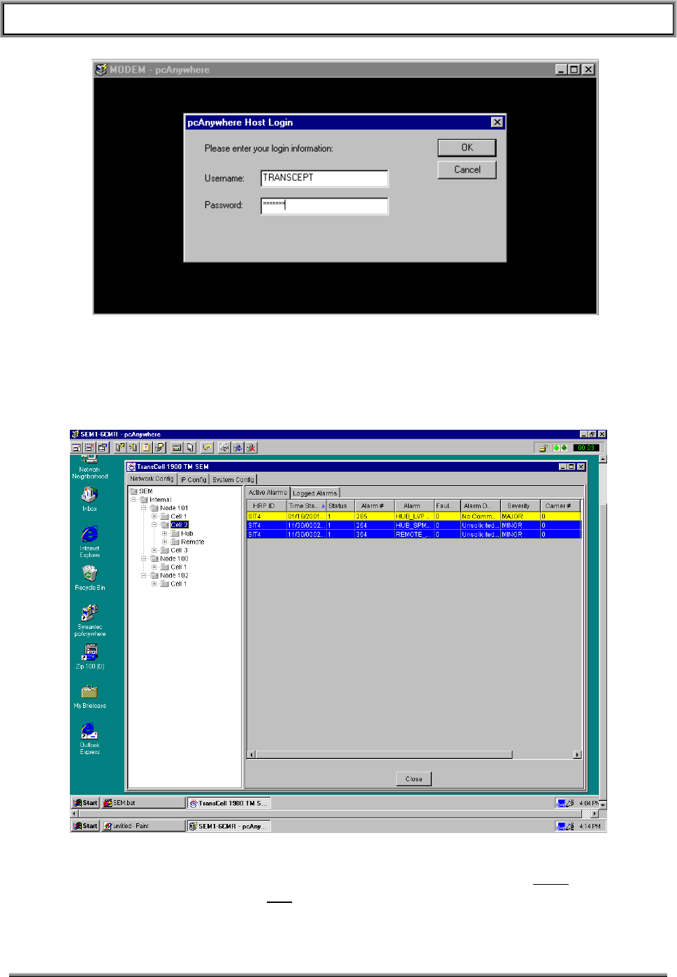
TransCell 1900TM SEM/HUI User’s Guide Document No. 1000483 A
Page 33
TRANSCEPT PROPRIETARY - DATA ON THIS PAGE SUBJECT TO RESTRICTIONS CITED ON COVER AND TITLE
Figure 5-12. Remote Login GUI
d. If everything was entered correctly pcAnywhere will display the SEM’s desktop on
the remote workstation as shown in Figure 5-13. You may now monitor system
activity and modify SEM parameters as if you were local to the SEM workstation.
Figure 5-13. Remote SEM Session
e. To disconnect the pcAnywhere session, press the button with the red X (rightmost
button), and then click the Yes button on the resulting popup GUI.

TransCell 1900TM SEM/HUI User’s Guide Document No. 1000483 A
Page 34
TRANSCEPT PROPRIETARY - DATA ON THIS PAGE SUBJECT TO RESTRICTIONS CITED ON COVER AND TITLE
6. HUI OPERATION
6.1 HUI
6.1.1 Launching HUI Software
The Windows NT Desktop is displayed at power-up or reset. At the Windows NT
Desktop, perform the following steps to the initialize HUI software application:
• If a HRP User icon is displayed on the Windows NT Desktop, double-click the icon to
start HUI software application. The HRP User dialog shown in Figure 3-1 appears.
• If no HRP User icon is displayed:
♦ Launch Windows NT Explorer by right clicking the Start button and selecting
Explore. The Windows NT Explorer Window appears.
♦ Using Windows NT Explorer, locate HRPUser.bat file in
C:\dev\classes\com\Transcept\tdma, and double-click on file name. The HRP User
dialog shown in Figure 3-1 appears.
6.1.2 Logging In via HUI
To log in to the HRP User Interface, perform the following steps:
• At IP Address: box of HRP User dialog, click on down arrow, and select an IP
address by clicking on it once.
• After selecting IP address, an HRP Login dialog appears. Type user password
(currently 123), and click OK. The HRP ID: box will display name of site logged into.
The Status: box will indicate Connected.
• Commands may now be entered into HRP Command: box of HRP User dialog. See
Section 7.2 for a list of the commands and command language syntax.
NOTE
All commands to and responses from the HRP, along
with any errors, are echoed in the HRP Response
window of the HRP User dialog. They are also entered
into a log file in the C:\Logfiles folder.
6.1.3 Logging Out
To log out of the HRP User Interface, type the command LOGOUT HRP in HRP
Command: box of HRP User dialog, or select None in IP Address: box.
6.1.4 Closing HUI Software
Closing HUI software is similar to exiting from most other Windows NT based
programs. To initiate the HUI software shutdown routine, select the X box at the upper
right corner of the HRP User dialog. This shutdown will log out of any active HRP
session and close the HRP User software.

TransCell 1900TM SEM/HUI User’s Guide Document No. 1000483 A
Page 35
TRANSCEPT PROPRIETARY - DATA ON THIS PAGE SUBJECT TO RESTRICTIONS CITED ON COVER AND TITLE
6.1.5 Portable Computer IP Address Change Procedure (For Local HUI Use)
To log into the Hub or Remote SPM at the local cell site, it is necessary to set the IP
address in the TCP/IP setup file on the laptop computer being used as the HUI. (The
computer must also have the HUI software installed.)
Note: If operating a HUI non-locally, i.e. on the customer’s network, DO NOT follow
these steps.
6.1.5.1 Setting Computer TCP/IP Configuration
The computer’s new IP address must be set to be in the same subnet as the SPM’s IP
address. The IP address to be used via the SPM’s ethernet port can be obtained from
the network file located in the /etc directory of the SPM’s filesystem.
To obtain this IP address from the SPM.
• connect the laptop’s COM1 serial port to the SPM’s console port.
• Open the Hyperterminal application direct on COM1.
• Setup the COM1 port for 9600 baud, 8 bits, no parity, 1 stop bit (9600-8-N-1).
• Hit the “Enter” key to obtain a login prompt.
• Login to the SPM with login: user and password: maintain
• At the # prompt enter cat /etc/network.
• Check the display for the address next to ETH_IP=. Record this IP address as it will
be what you use to communicate with this SPM.
• In Hyperterminal type exit to logout of the SPM.
You must now set your laptop to be in the same subnet as the SPM. Before changing IP
parameters on your laptop computer, record ALL settings that are to be changed. These
parameters may need to be re-entered after the SPM has been re-configured. Perform
the following steps to log into a SPM:
Connect a crossover 8-pin Ethernet® cable from laptop’s Ethernet port to the ENET
port on the SPM.
Right-click on Network Neighborhood icon on Windows NT® Desktop to display popup
menu shown in Figure 6-1. Network Neighborhood Pop-up
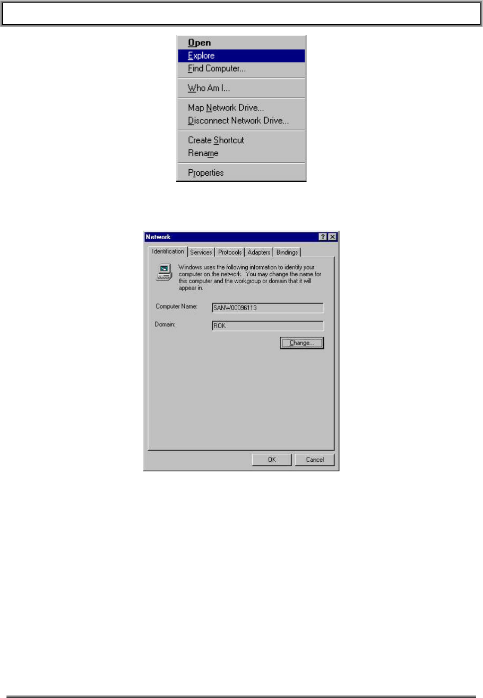
TransCell 1900TM SEM/HUI User’s Guide Document No. 1000483 A
Page 36
TRANSCEPT PROPRIETARY - DATA ON THIS PAGE SUBJECT TO RESTRICTIONS CITED ON COVER AND TITLE
Figure 6-1. Network Neighborhood Pop-up
Click on Properties to display Network dialog.
Figure 6-2. Network Dialog
At Network dialog, click on Protocols tab to display Network Protocols: selection window.
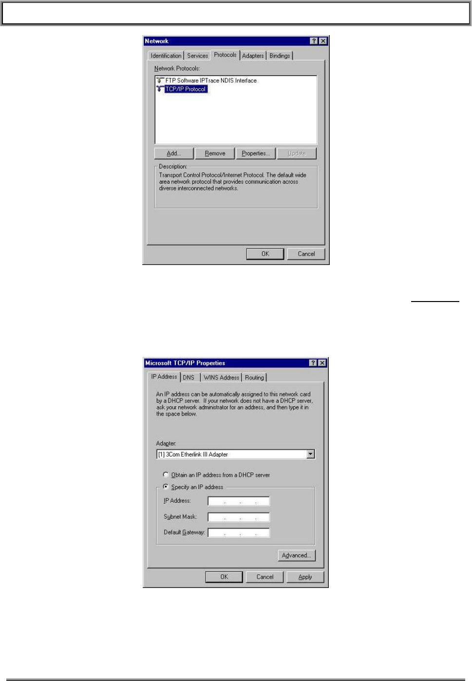
TransCell 1900TM SEM/HUI User’s Guide Document No. 1000483 A
Page 37
TRANSCEPT PROPRIETARY - DATA ON THIS PAGE SUBJECT TO RESTRICTIONS CITED ON COVER AND TITLE
Figure 6-3. Network Protocols Selection Window
In Network Protocols: selection window, click on TCP/IP Protocol, then select Properties
to display Microsoft TCP/IP Properties dialog (Figure 6-4. Microsoft TCP/IP Properties
Dialog
Figure 6-4. Microsoft TCP/IP Properties Dialog
In Microsoft TCP/IP Properties dialog (IP Address tab defaulted), click on Specify an IP
Address button.
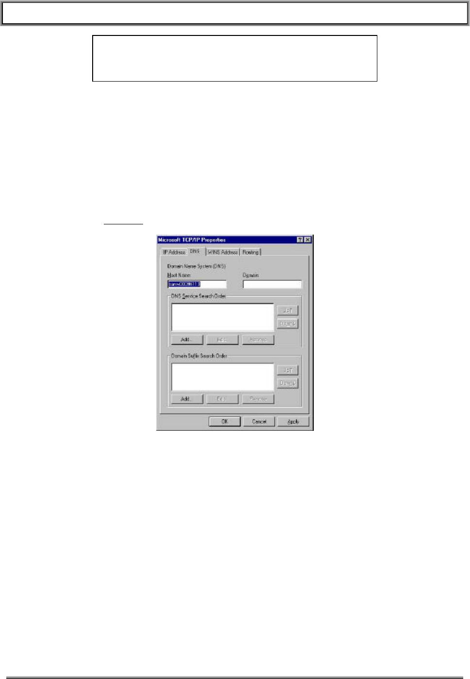
TransCell 1900TM SEM/HUI User’s Guide Document No. 1000483 A
Page 38
TRANSCEPT PROPRIETARY - DATA ON THIS PAGE SUBJECT TO RESTRICTIONS CITED ON COVER AND TITLE
NOTE
Before changing any values, record the present values. You may
have to re-enter them after the SPM is configured.
• In IP Address: box, enter an address that is 1 number higher than number you
recorded from the SPM. For example: If the SPM has 10.10.117.21, enter
10.10.117.22.
• In Subnet Mask: box, enter a Subnet Mask number: Use 255.255.255.0.
• Leave Default Gateway: box blank.
In Microsoft TCP/IP Properties dialog, select DNS tab (see Figure 6-5. Microsoft
TCP/IP Properties Dialog – DNS Tab
and disable DNS by highlighting IP Address in DNS Service Search Order window and
then clicking Remove.
Figure 6-5. Microsoft TCP/IP Properties Dialog – DNS Tab
In Microsoft TCP/IP Properties dialog, select WINS Address tab (See Figure 6-6.
Microsoft TCP/IP Properties Dialog – WINS Address Tab
and disable (uncheck) Enable DNS for Windows Resolution button.
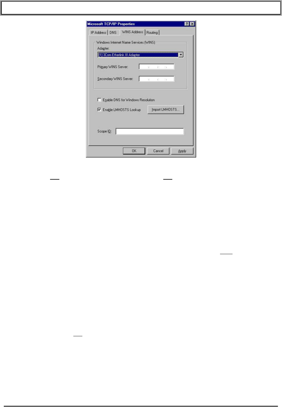
TransCell 1900TM SEM/HUI User’s Guide Document No. 1000483 A
Page 39
TRANSCEPT PROPRIETARY - DATA ON THIS PAGE SUBJECT TO RESTRICTIONS CITED ON COVER AND TITLE
Figure 6-6. Microsoft TCP/IP Properties Dialog – WINS Address Tab
Click on OK to return to Protocols tab; then click OK again to get back to Windows NT
Desktop.
Reboot computer so new IP address can take affect.
Modify Computer Configuration File (IPAddresses.txt)
• Launch the HUI software and select Edit-Edit IP Addresses. The IP Address editor
will appear.
• Check to see if target or factory IP address(es) (that you recorded at the beginning of
this section) is/are listed in file. If address(es) is/are not listed, add them by typing the
IP address into the area provided (see Figure 3-3) and press the Add button.
Log Into SPM with HUI Software
At the Windows NT Desktop on your computer, double-click on the HRP User icon to
start the HUI software. The HUI software is now running and the HRP User dialog is
displayed (see Figure 3-1). Perform the following steps to log into a SPM and send
commands to it:
At HRP User dialog, click down arrow on IP Address:. Locate and click on factory IP
address of SPM.
Once IP Address has been selected, HRP Login dialog appears. Type password (default
is 123) and click OK. A message confirming the login will appear in the HRP Response
window.
Commands may now be sent to the SPM.
6.1.5.2 Restore Computer TCP/IP Configuration
If required, the computer's settings that were changed in paragraph 6.1.5.1 have to be
restored to their original settings. Refer to the settings previously recorded to change
IP settings.

TransCell 1900TM SEM/HUI User’s Guide Document No. 1000483 A
Page 40
TRANSCEPT PROPRIETARY - DATA ON THIS PAGE SUBJECT TO RESTRICTIONS CITED ON COVER AND TITLE
6.1.6 HUI Script Files
Script files are ASCII text files that contain commands a user would normally type in the
HRP Command: text box. Script files are particularly useful when information is needed
about a module or group of modules in the HRP. Script files are also useful when setting
up the system. Table 6-1 describes some useful HUI script files. These are located in
C:\config\Scripts.
Table 6-1. HUI Scripts
Script Filename Script File Description
AutolevelParams.txt Gets all autolevel related parameters
DisablePAs.txt Disables all PAs
DLMParams.txt Calls Hub and Remote DLM params scripts
EnableFaults.txt Enables XTM, DLM, PA faults
EanblePAs.txt Enables all PAs
GetOpenAlarms.txt Retrieves all active alarms on the local SPM
HubDlmParams.txt Gets all the Hub DLM parameters
LocalSpmParams.txt Gets the parameters of the local SPM
RemDlmParams.txt Gets all Remote DLM parameters
RevAgcParams.txt Gets all autolevel related parameters
SetDlmGain.txt Sets Hub and Remote DLM Attenuators
SetHrpGain.txt Calls all “set gain and atten” scripts
SetHtmGain.txt Sets up HTM Attenuators per installation guide
SetHubSpmGain.txt Sets the Hub SPM Gain and Attenuator values
SetRemSpmGain.txt Sets the Remote SPM Gain and Attenuator values
SetRtmGain.txt Sets up RTM Attenuators per installation guide

TransCell 1900TM SEM/HUI User’s Guide Document No. 1000483 A
Page 41
TRANSCEPT PROPRIETARY - DATA ON THIS PAGE SUBJECT TO RESTRICTIONS CITED ON COVER AND TITLE
7. COMMAND LINE INTERFACE (CLI)
The HRP User Interface software provides a command line interface for the user’s
computer to communicate with any Hub or Remote Subsystem on the user’s network.
Network communications with the HRPs are via a V.35 interface built into the SPM at the
Hub. Portable computers at the tower site may communicate locally with a Hub or
Remote SPM via the SPM’s built-in ethernet interface.
7.1 HRP COMMAND LANGUAGE OVERVIEW
This section describes the Command Line Interface (CLI) protocol which is used to
interface to the SPM software in the TransCell® 1900TM system. The protocol is ASCII
based, with text messages transmitted to and from the SPM via TCP/IP. The CLI
protocol is designed to allow for an orderly flow of information that is easier to
understand when typing commands and when writing code to support the protocol.
This protocol has the following features:
• The delimiter between all fields is a space. This makes it easier to type commands at
a prompt and also conforms to the Microsoft® Excel standard for reading table-
based text files into a spreadsheet, which will be useful when evaluating message
traffic logs.
• Any number of tabs or spaces may be used to delimit the fields in the message.
• A conscious effort has been made to eliminate the use of underscores ("_") in the
field names of messages, since these characters can be cumbersome to type.
• The text-based fields of the message are case-insensitive.
NOTE
In the following HRP Command Language message
descriptions, the square brackets used to delineate each
field are not part of the actual message format.
Field Types
The following are the field types used in the messages. Keep in mind that not all
messages use all of the fields. The specifics of a given message is dictated by the
message type, the device, and the parameter of the message:
HEADER The HUI application prefixes a header field to all messages sent to the
SPM for the purpose of synchronizing messages. This HEADER field
is designated by a '$' before and after the header value. The SPM
prefixes the same HEADER to the response message. The HEADER
field is not echoed to any of the user displays.
RESPONSE This field indicates the type of response to an input message. The
allowable types in this field are "REPORT", "CONFIRM" and "NACK".
All negative responses will be in the form of a “NACK”, requests for
information will be responded to with a “REPORT”, and successful
sets/resets/commands will be responded to with a “CONFIRM”.
TYPE This field indicates the intent of a request message. The following are
the allowable message types: "SET", "GET", "RESET", "LOGIN",
"LOGOUT", “WRITE”, and “CLOSE” (for alarms).

TransCell 1900TM SEM/HUI User’s Guide Document No. 1000483 A
Page 42
TRANSCEPT PROPRIETARY - DATA ON THIS PAGE SUBJECT TO RESTRICTIONS CITED ON COVER AND TITLE
DEVICE This field indicates the device (one only per message) that affects or
is affected by this message. The only allowable device names are:
“HRP" (Hub-Remote-Pair) "HUBDLM" (Hub-side Datalink Module)
“HUBSPM" (Hub-side SPM) "REMDLM" (Remote-side DLM)
"REMSPM" (Remote-side SPM) "HTM" (Hub Transceiver Module)
"LOCALSPM" ("this" side SPM) "RTM" (Remote Transceiver Module)
"OTHERSPM" ("that" side SPM)
“HUBLVPS” (Hub Low Volt Power Supply)
“REMLVPS” (Remote Low Volt Power Supply)
“PSUPPLY” (Power Supply)
“PA” (Power Amplifier)
“AUTOLEVEL”
“TTA” (Tower Top Amplifier)
NOTE: “This” side refers to the SPM to which the user is locally connected and “that” side
refers to the SPM that “this” side communicates to across the datalink.
PARAM This field indicates the parameter that is requested or transmitted in a
given message. The use of this field is completely dependent on the
device type. See the individual message type descriptions for valid
parameter names.
CARRIER This field indicates the carrier that is requested in a message. For
example, in a six-carrier system configuration, the only valid carrier
values will be 1 through 6. Not all commands/messages use this field;
it depends on the device/parameter that is being controlled.
VALUE This field indicates the value of the parameter for a given message.
The use of this field is dependent on the message type, and possibly
the parameter type. See the individual message type descriptions for
valid value ranges.
ERROR This field provides the error codes that can be given in the NACK
message.
EOM This is the end of message character, which for the HRP User
Interface (HUI) is the sequence "\r\n". The EOM field is not echoed to
any of the user displays.
7.2 COMMANDS
7.2.1 SET Message
The SET message is used to set the following parameters within an HRP:
• PCS Channel – Settable at HRP, Hub or Remote level
• Data Link Channel – forward or reverse, settable at HRP, Hub or Remote level
• Alarm Enable States – settable at HRP level only
• Thresholds – Alarms, faults
• Scheduled Events – Fault processing, watchdog, etc.
• Gender – Tells SPM if it is on Hub or Remote side
TransCell 1900TM SEM/HUI User’s Guide Document No. 1000483 A
Page 43
TRANSCEPT PROPRIETARY - DATA ON THIS PAGE SUBJECT TO RESTRICTIONS CITED ON COVER AND TITLE
• HRP Identifier – 1 to 31 characters; user defined identifier; used in alarm reporting
• PA Enable State - Select by Remote Transceiver Module (RTM) number
• Attenuators – Forward; primary/diversity reverse; settable at HTM, RTM or
Hub/Remote level; digital attenuators
The following describes the format of this message type:
• [HEADER]
• "SET"
• [DEVICE]
• [PARAM]
• [CARRIER] (possible, depends on parameter)
• [VALUE] (possible, depends on parameter)
• [MISC] (possible, depends on parameter)
• [EOM]
The response to this message by the SPM will contain the request message with either
a "CONFIRM" or "NACK" field being inserted as the first field. In the case of the
message being NACKed, the [ERROR] field will contain the error code(s) explaining why
the message could not be processed. The following is the response template:
If command successful: [HEADER] CONFIRM: [ECHO OF REQUEST MESSAGE]
If command unsuccessful: [HEADER] NACK: [ERROR]
The following table defines the valid devices, parameters, carriers, and values that are
allowed in the SET message. There is also a secondary field called “Misc” for any
additional data. This field is displayed in the table below only if it is needed (it will also
appear shaded):
Table 7-1. CLI Set Commands
Device Parameter Carrier Value Misc Description
HRP TDMACHAN 1 – 6 2 – 1998 (overall,
limited by band) Sets the HTM and RTM Channel and
Updates the DDC/DUC Frequencies
HRP DCCH 1 – 6 Sets the DCCH on the Hub and Remote
HRP ALMSTATE XXX Y XXX = Alarm Number, Y = 0/1 (off/on)
LOCALSPM GENDER HUB or REMOTE Sets the Gender of this SPM
LOCALSPM TIME 0 – 232 Set Time (Seconds since 1/1/1970) on
this SPM
LOCALSPM ID 1 – 31 chars Sets the HRP ID of this SPM
LOCALSPM DCCH 1 – 6 Sets the DCCH Carrier of this SPM
LOCALSPM SHUTDOWN Causes this Executive to Shutdown
HUBSPM TIME 0 – 232 Set time (Seconds since 1/1/1970) on
Hub SPM
HUBSPM ID 1 – 31 chars Sets the ID of the Hub SPM
HUBSPM DCCH 1 – 6 Sets the DCCH on the Hub SPM
HUBSPM REGISTER Xxxxxxxx yyyy 32-bit Address/16-bit Word to Write

TransCell 1900TM SEM/HUI User’s Guide Document No. 1000483 A
Page 44
TRANSCEPT PROPRIETARY - DATA ON THIS PAGE SUBJECT TO RESTRICTIONS CITED ON COVER AND TITLE
Device Parameter Carrier Value Misc Description
HUBSPM FWGAIN 1 – 6 0 – 95.9 Sets DDC Gain on Main Path
HUBSPM RFWGAIN 1 – 6 0 – 95.9 Sets DDC Gain on Redundant Path
HUBSPM PRVATTEN 1 – 6 0 – 48 Sets DUC Attenuation
HUBSPM DRVATTEN 1 – 6 0 – 48 Sets DUC Attenuation
HUBSPM TEMPFAULTS Sets the Hub SPM Temperature Faults
HUBDLM FWCHAN 1,2,5,6 (A or B) Sets Hub DLM Forward Channel
HUBDLM RVCHAN 1,2,5,6 (A or B) Sets Hub DLM Reverse Channel
HUBDLM FWSTATE 0 – 1 Sets Forward Radio (0=off,1=on)
HUBDLM RVSTATE 0 – 1 Sets Reverse Radio (0=off, 1=on)
HUBDLM AUTOSYNC 0 – 1 Sets Auto Sync State (0=off, 1=on)
HUBDLM FWATTEN 0 – 31 Sets Hub DLM Forward Attenuation
HUBDLM FLTSTATES Sets Hub DLM Faults (bitmap)
HUBDLM LOOPBACK 0 – 1 Sets Loopback Enable State (0=off,1=on)
RAGC HUBSTATE 0 – 1 Enables Hub Reverse AGC
RAGC REMSTATE 0 – 1 Enables Remote Reverse AGC
RAGC RATE 10 – 720 Sets Reverse AGC Rate (in minutes)
RAGC SETPOINT 8 – 14 Sets Reverse AGC Setpoint (Hub)
RAGC SECTORS 1 – 3 Sets Number of Sectors (Remote)
RAGC TMAMODE 0 – 1 Enables/Disables TMA Mode (Remote)
RAGC GO Kicks off Reverse AGC
RAGC HUBGO Kicks off Reverse AGC (Hub)
RAGC REMGO Kicks off Reverse AGC (Remote)
RAGC FLTSTATES Sets Reverse AGC Faults (bitmap)
REMSPM TIME 0 – 232 Set Time (Seconds since 1/1/1970) on
Remote SPM
REMSPM ID 1 – 31 chars Sets the ID of the Remote SPM
REMSPM DCCH 1 – 6 Sets the DCCH on the Remote SPM
REMSPM REGISTER Xxxxxxxx yyyy 32-bit Address/16-bit Word to Write
REMSPM FWATTEN 1 – 6 0 – 48 Sets DUC Attenuation (Main)
REMSPM RFWATTEN 1 – 6 0 – 48 Sets DUC Attenuation (Backup)
REMSPM PRVGAIN 1 – 6 0 – 95.9 Sets DDC Gain
REMSPM DRVGAIN 1 – 6 0 – 95.9 Sets DDC Gain
REMSPM TEMPFAULTS Sets Remote SPM Temperature Faults
REMSPM RVFILTER Filter Name Sets DDC Filter. Do not include
pri/div.r0 in filter name
REMDLM FWCHAN 1,2, 5,6 (A or B) Sets Remote DLM Forward Channel
REMDLM RVCHAN 1,2, 5,6 (A or B) Sets Remote DLM Reverse Channel
REMDLM FWSTATE 0 – 1 Sets Forward Radio (0=off,1=on)
REMDLM RVSTATE 0 – 1 Sets Reverse Radio (0=off, 1=on)
REMDLM AUTOSYNC 0 – 1 Sets Auto Sync State (0=off, 1=on)
REMDLM RVATTEN 0 – 31 Sets Remote DLM Reverse Attenuation
REMDLM FLTSTATES Sets Remote DLM Faults (bitmap)
REMDLM LOOPBACK 0 – 1 Sets Loopback Enable State (0=off,1=on)
HTM TDMACHAN 1 – 6 2 – 1998 (overall,
limited by band) Sets HTM TDMA Channel and Updates
the DDC/DUC Frequencies

TransCell 1900TM SEM/HUI User’s Guide Document No. 1000483 A
Page 45
TRANSCEPT PROPRIETARY - DATA ON THIS PAGE SUBJECT TO RESTRICTIONS CITED ON COVER AND TITLE
Device Parameter Carrier Value Misc Description
HTM FWATTEN 0-15 Sets HTM Fwd Atten (Main Path)
HTM RFWATTEN 0-15 Sets HTM Fwd Atten (Redundant Path)
HTM PRVATTEN UPPER or
LOWER
0-15 Sets HTM Primary Reverse Attenuation
HTM DRVATTEN UPPER or
LOWER
0-15 Sets HTM Diversity Reverse Attenuation
HTM BAND A – F Set Band of HTM and Updates
DDCs/DUCs with New Band Defaults
HTM FLTSTATES Sets HTM Faults (bitmap)
RTM TDMACHAN 1 – 6 2 – 1998 (overall,
limited by band) Sets RTM TDMA Channel and Updates
the DDC/DUC Frequencies
RTM PRVATTEN 0 – 15 Sets RTM Primary Reverse Attenuation
RTM DRVATTEN 0 – 15 Sets RTM Diversity Reverse Attenuation
RTM BAND A – F Set Band of RTM and Updates
DDCs/DUCs with New Band Defaults
RTM FREQPLAN A,B,C Set Frequency Plan of RTM and
Updates DDCs/DUCs with New Freqs
RTM PRVTONE 0, 120.000-160.000 0 = Disable Tone, Any Other Value =
Enable at Given Frequency
RTM DRVTONE 0, 120.000-160.000 0 = Disable Tone, Any Other Value =
Enable at Given Frequency
RTM FLTSTATES Sets RTM Faults (bitmap)
PA STATE 1 – 6 0 – 1 Enable/Disable PA Unit (1 = enable)
PA DLMLOCK 0 – 1 Notify PA if Link is Locked/Unlocked
PA FLTSTATES Sets PA Faults (bitmap)
HUBLVPS FLTSTATES Sets Hub LVPS Faults (bitmap)
REMLVPS FLTSTATES Sets Remote LVPS Faults (bitmap)
PSUPPLY FLTSTATES Sets Power Supply Faults (bitmap)
AUTOLEVEL RATE 1 – 15 Rate (in minutes) at Which to Perform
Autolevel Processing
AUTOLEVEL STATE 0 – 1 Enable/Disable Autolevelling (1 = on)
AUTOLEVEL GO Kick off Autolevel Process
AUTOLEVEL BACKOFF 1.0 – 5.0 Set Autolevel Backoff Level
AUTOLEVEL SETPOINT 40.0 – 50.0 Set Autolevel Setpoint Value
AUTOLEVEL TOLERANCE 0.0 – 1.0 Set Autolevel Setpoint Tolerance Value
FCONT STATE 0 – 1 Enable/Disable Forward Continuity
FCONT GO Kick off Forward Continuity Cycle
RCONT STATE 0 – 1 Enable/Disable Reverse Continuity
RCONT GO Kick off Reverse Continuity Cycle
7.2.2 GET Message
The GET message is used to get following parameters within HRP.
• PCS Channel

TransCell 1900TM SEM/HUI User’s Guide Document No. 1000483 A
Page 46
TRANSCEPT PROPRIETARY - DATA ON THIS PAGE SUBJECT TO RESTRICTIONS CITED ON COVER AND TITLE
• Data Link Channel – forward/reverse channel, lock state, Bit Error Rate
• Alarm Enable States
• HRP Identifier
• Temperature Values – HTM, RTM (Fwd, Rev, PA)
• Attenuator Power Values – Forward; primary/diversity reverse; request at a HTM,
RTM, Hub/Remote level; digital attenuators
• Software Revisions – HTM, RTM, SPM
• PA – State (on/off); power
The following describes the format of this message type:
• [HEADER]
• "GET"
• [DEVICE]
• [PARAM]
• [CARRIER] (possible, depends on parameter)
• [VALUE] (possible, depends on parameter)
• [EOM]
The return message type will be one of two types: either "REPORT" if successful or
"NACK" if unsuccessful. In the case of a "REPORT" return, the return value(s) will be
indicated in the [VALUE] field. In the case of a "NACK" return (either because of an
invalid request format or some other processing reason), the error code(s) will be
indicated in the [ERROR] field. The return message will take on the following form:
If command successful: [HEADER] REPORT: [VALUE]
If command unsuccessful: [HEADER] NACK: [ERROR]
For some cases of successful “GET LOCALSPM” type commands, the response format
will be slightly modified to accommodate the HUI software:
[HEADER] REPORT [PARAM]: [VALUE]
The following table defines the valid devices, parameters, indices, and values that are
allowed in the GET message:
Table 7-2. CLI Get Commands
Device Parameter Carrier Value Return Values
HRP TDMACHAN 1 – 6 TDMA Channel – Validation is Done to be Sure
that Both Sides are Synched
HRP DCCH System DCCH – Validation is Done to be Sure
that Both Sides are Synched
HRP ALMSTATE XYZ HRP Alarm State (1 = on) Corresponding to
Alarm Number XYZ
LOCALSPM GENDER "HUB" or "REMOTE" from this SPM
LOCALSPM VERSION Executive Software Version of this SPM
LOCALSPM ID User Defined ID of this SPM

TransCell 1900TM SEM/HUI User’s Guide Document No. 1000483 A
Page 47
TRANSCEPT PROPRIETARY - DATA ON THIS PAGE SUBJECT TO RESTRICTIONS CITED ON COVER AND TITLE
Device Parameter Carrier Value Return Values
LOCALSPM TIME Time (in Seconds) of this SPM
LOCALSPM DCCH The DCCH Carrier set on this SPM
LOCALSPM OPENALMS All Potential Alarms from this SPM
LOCALSPM PRIVLEVEL The Current Privilege Level of Logged In User
OTHERSPM GENDER “HUB” or “REMOTE” from “that” SPM
OTHERSPM VERSION Executive Software Version of “that” SPM
OTHERSPM ID User Defined ID of “that” SPM
OTHERSPM TIME Time (in Seconds) of “that” SPM
OTHERSPM DCCH The DCCH Carrier set on “that” SPM
HUBSPM TIME Time (in Seconds) of Hub SPM
HUBSPM DCCH Hub SPM DCCH (1 – 6)
HUBSPM ID Hub ID (auto-updated by SEM)
HUBSPM VERSION Hub Executive Software Version
HUBSPM FWGAIN 1 – 6 Hub DDC (Forward Main) Gain
HUBSPM RFWGAIN 1 – 6 Hub DDC (Forward Redundant) Gain
HUBSPM PRVATTEN 1 – 6 Hub DUC (Primary Reverse) Attenuation
HUBSPM DRVATTEN 1 – 6 Hub DUC (Diversity Reverse) Attenuation
HUBSPM FWFREQ 1 – 6 Hub DDC (Forward Main) Frequency
HUBSPM RFWFREQ 1 – 6 Hub DDC (Forward Redundant) Frequency
HUBSPM PRVFREQ 1 – 6 Hub DUC (Primary Reverse) Frequency
HUBSPM DRVFREQ 1 – 6 Hub DUC (Diversity Reverse) Frequency
HUBSPM FWPOWER 1 – 6 Hub DDC (Forward Main) Power
HUBSPM RFWPOWER 1 – 6 Hub DDC (Forward Redundant) Power
HUBSPM PRVPOWER 1 – 6 Hub DUC (Primary Reverse) Power
HUBSPM DRVPOWER 1 – 6 Hub DUC (Diversity Reverse) Power
HUBSPM TEMP Hub SPM Temperature
HUBSPM TEMPFAULTS Hub SPM Temperature Fault States (bitmap)
HUBSPM REGISTER xxxxxxxx Hub FPGA Address value. Given a 32-bit Hex
Address (xxxxxxxx), Returns a 16-bit Value.
HUBDLM FWCHAN Hub DLM Forward Channel
HUBDLM RVCHAN Hub DLM Reverse Channel
HUBDLM BERONE Hub DLM One Sample Bit Error Rate
HUBDLM BERTEN Hub DLM Ten Sample Bit Error Rate
HUBDLM BERACCUM Hub DLM Accumulated Bit Error Rate
HUBDLM LOCK Hub DLM Lock State (1 = locked)
HUBDLM FWSTATE Hub DLM Forward Radio (1 = enabled)
HUBDLM RVSTATE Hub DLM Reverse Radio (1 = enabled)
HUBDLM AUTOSYNC Hub DLM Auto Sync (1 = enabled)
HUBDLM FLTSTATES Hub DLM Fault States (bitmap)
HUBDLM FWATTEN Hub DLM Forward Attenuation Value
HUBDLM FWPOWER Hub DLM Forward Power Value
HUBDLM LOOPBACK Hub Loopback Enable State (0=off,1=on)
RAGC HUBSTATE Hub Reverse AGC State
RAGC REMSTATE Remote Reverse AGC State

TransCell 1900TM SEM/HUI User’s Guide Document No. 1000483 A
Page 48
TRANSCEPT PROPRIETARY - DATA ON THIS PAGE SUBJECT TO RESTRICTIONS CITED ON COVER AND TITLE
Device Parameter Carrier Value Return Values
RAGC RATE Reverse AGC Rate (in minutes)
RAGC SETPOINT Reverse AGC Setpoint (Hub)
RAGC SECTORS Number of Sectors (Remote)
RAGC TMAMODE TMA Mode (Remote)
RAGC FLTSTATES Reverse AGC Faults (bitmap)
REMSPM TIME Time (in Seconds) of Remote SPM
REMSPM DCCH Remote SPM DCCH (1 – 6)
REMSPM ID Remote ID (auto-updated by Hub Executive)
REMSPM VERSION Remote Executive Software Version
REMSPM FWATTEN 1 – 6 Remote DUC (Forward Main) Attenuation
REMSPM RFWATTEN 1 – 6 Remote DUC (Forward Redundant) Attenuation
REMSPM PRVGAIN 1 – 6 Remote DDC (Primary Reverse) Gain
REMSPM DRVGAIN 1 – 6 Remote DDC (Diversity Reverse) Gain
REMSPM FWFREQ 1 – 6 Remote DUC (Forward Main) Frequency
REMSPM RFWFREQ 1 – 6 Remote DUC (Forward Redundant) Frequency
REMSPM PRVFREQ 1 – 6 Remote DDC (Primary Reverse) Frequency
REMSPM DRVFREQ 1 – 6 Remote DDC (Diversity Reverse) Frequency
REMSPM FWPOWER 1 – 6 Remote DUC (Forward Main) Power
REMSPM RFWPOWER 1 – 6 Remote DUC (Forward Redundant) Power
REMSPM PRVPOWER 1 – 6 Remote DDC (Primary Reverse) Power
REMSPM DRVPOWER 1 – 6 Remote DDC (Diversity Reverse) Power
REMSPM TEMP Remote SPM Temperature
REMSPM TEMPFAULTS Remote SPM Temp Fault States (bitmap)
REMSPM REGISTER xxxxxxxx Remote FPGA Address Value. Given a 32-bit
Hex Address (xxxxxxxx), Returns a 16-bit Value
REMSPM RVFILTER DDC Filter Name
REMDLM FWCHAN Remote DLM Forward Channel
REMDLM RVCHAN Remote DLM Reverse Channel
REMDLM BERONE Remote DLM One Sample BER
REMDLM BERTEN Remote DLM Ten Sample BER
REMDLM BERACCUM Remote DLM Accumulated BER
REMDLM LOCK Remote DLM Lock State (1 = locked)
REMDLM FWSTATE Remote DLM Forward Radio (1 = enabled)
REMDLM RVSTATE Remote DLM Reverse Radio (1 = enabled)
REMDLM AUTOSYNC Remote DLM Auto Sync (1 = enabled)
REMDLM FLTSTATES Remote DLM Fault States (bitmap)
REMDLM RVATTEN Remote DLM Reverse Attenuation Value
REMDLM RVPOWER Remote DLM Reverse Power Value
REMDLM LOOPBACK Loopback Enable State (0=off,1=on)
HTM TDMACHAN 1 – 6 HTM TDMA Channel and DDC/DUC Freqs
HTM FWATTEN HTM Forward Main Attenuation
HTM RFWATTEN HTM Forward Redundant Attenuation
HTM PRVATTEN UPPER or
LOWER
HTM Primary Reverse Attenuation

TransCell 1900TM SEM/HUI User’s Guide Document No. 1000483 A
Page 49
TRANSCEPT PROPRIETARY - DATA ON THIS PAGE SUBJECT TO RESTRICTIONS CITED ON COVER AND TITLE
Device Parameter Carrier Value Return Values
HTM DRVATTEN UPPER or
LOWER
HTM Diversity Reverse Attenuation
HTM PRVPOWER UPPER or
LOWER
HTM Primary Reverse Power
HTM DRVPOWER UPPER or
LOWER
HTM Diversity Reverse Power
HTM TEMP HTM Temperature
HTM BAND HTM TDMA Band (A – F)
HTM FLTSTATES HTM Fault States (bitmap)
RTM TDMACHAN 1 – 6 RTM TDMA Channel and DDC/DUC Freqs
RTM PRVATTEN RTM Primary Reverse Attenuation
RTM DRVATTEN RTM Diversity Reverse Attenuation
RTM FWPOWER 1 – 6 RTM Forward Power
RTM TEMP RTM Temperature
RTM FREQPLAN RTM Frequency Plan (A – C)
RTM BAND RTM TDMA Band (A – F)
RTM FLTSTATES RTM Fault States (bitmap)
RTM PRVTONE Frequency (in MHz) of Primary Test Tone
(0=Tone disabled)
RTM DRVTONE Frequency (in MHz) of Diversity Test Tone
(0=Tone disabled)
PA TEMP 1 – 6 PA Temperature
PA STATE 1 – 6 PA State (1 = enabled)
PA FWPOWER 1 – 6 PA Forward Power Value
PA VOLTAGE 1 – 6 PA Input Voltage Reading
PA POSITION 1 – 6 PA Position in Rack
PA HWREV 1 – 6 PA Hardware Revision Information
PA SWREV 1 – 6 PA Software Revision Information
PA SERIALNUM 1 – 6 PA Serial Number
PA FLTSTATES PA Fault States
HUBLVPS FLTSTATES Hub LVPS Fault States (bitmap)
REMLVPS FLTSTATES Remote LVPS Fault States (bitmap)
PSUPPLY FLTSTATES Power Supply Fault States (bitmap)
AUTOLEVEL RATE Rate (in minutes) Autolevel Process is Run
AUTOLEVEL STATE Autolevel Process State (1 = enabled)
AUTOLEVEL BACKOFF Autolevel Backoff Value
AUTOLEVEL SETPOINT Autolevel Setpoint
AUTOLEVEL TOLERANCE Autolevel Setpoint Tolerance
FCONT STATE Forward Continuity Enable State
RCONT STATE Reverse Continuity Enable State

TransCell 1900TM SEM/HUI User’s Guide Document No. 1000483 A
Page 50
TRANSCEPT PROPRIETARY - DATA ON THIS PAGE SUBJECT TO RESTRICTIONS CITED ON COVER AND TITLE
7.2.3 RESET Message
This message is used to reset a given device. This request from the user will take on the
following form:
• [HEADER]
• "RESET"
• [DEVICE]
• [PARAM]
• [CARRIER] (possible, depends on device)
• [EOM]
The following table defines the valid devices, parameters, indices, and values that are
allowed in the RESET message:
Table 7-3. CLI Reset Commands
Device Parameter Carrier
HUBSPM FWPATH
HUBSPM RVPATH
HUBDLM DEVICE
HUBDLM BERCOUNT
REMSPM FWPATH
REMSPM RVPATH
REMDLM DEVICE
REMDLM BERCOUNT
HTM
RTM
PA 1 – 6
TTA
AUTOLEVEL BACKOFF
In this message, FWPATH, PRVPATH, and DRVPATH on either the HUB-side or
REMOTE-side SPM refers to the resetting of the DDCs and DUCs.
The AUTOLEVEL BACKOFF reset command will override the one-time autolevel
adjustment.
The response to this message by the SPM will contain the request message with either
a "CONFIRM" or "NACK" field being inserted as the first field. In the case of the
message being NACKed, the [ERROR] field will contain the error code(s) explaining why
the message could not be processed. The following is the response template:
If command successful: [HEADER] CONFIRM: [ECHO OF REQUEST MESSAGE]
If command unsuccessful: [HEADER] NACK: [ERROR]

TransCell 1900TM SEM/HUI User’s Guide Document No. 1000483 A
Page 51
TRANSCEPT PROPRIETARY - DATA ON THIS PAGE SUBJECT TO RESTRICTIONS CITED ON COVER AND TITLE
7.2.4 LOGIN Message
This message is used to allow the user to log in to the HUI. The software design requires
that a user be logged in before being allowed to monitor and control the system. (The
only exception to this is the use of certain “GET LOCALSPM” type messages). The user
will enter a password in the [VALUE] field. The LOGIN request will take on the following
form:
• [HEADER]
• "LOGIN"
• "LOCALSPM"
• [VALUE]
• [EOM]
The VALUE field will contain the password, which will be hard-coded in the SPM, some
alphanumeric string of 6 to 8 characters. There are currently two passwords allowed:
one which allows for “read-only” access and one which allows for “read-write” access.
The response to this message by the SPM will contain the request message with either
a "CONFIRM" or "NACK" field being inserted as the first field. In the case of the
message being NACKed, the [ERROR] field will contain the error code(s) explaining why
the message could not be processed. The following is the response template:
If command successful: [HEADER] CONFIRM: [ECHO OF REQUEST MESSAGE]
If command unsuccessful: [HEADER] NACK LOGIN: [ERROR]
7.2.5 LOGOUT Message
This message is used to log-out of the HRP. This command allows the SPM software to
reset the communications port and configure it to listen for a new LOGIN message. The
form of this message will be as follows:
• [HEADER]
• "LOGOUT"
• "LOCALSPM"
• [EOM]
The response to this message by the SPM will contain the request message with either
a "CONFIRM" or "NACK" field being inserted as the first field. In the case of the
message being NACKed, the [ERROR] field will contain the error code(s) explaining why
the message could not be processed. The following is the response template:
If command successful: [HEADER] CONFIRM: [ECHO OF REQUEST MESSAGE]
If command unsuccessful: [HEADER] NACK LOGOUT: [ERROR]
7.2.6 CLOSE Message
This message is used to allow the closing of alarms designated as “user-closeable”. The
form of this message is as follows, where the [VALUE] field contains the alarm ID and
the [MISC] field contains the fault ID:
• [HEADER]

TransCell 1900TM SEM/HUI User’s Guide Document No. 1000483 A
Page 52
TRANSCEPT PROPRIETARY - DATA ON THIS PAGE SUBJECT TO RESTRICTIONS CITED ON COVER AND TITLE
• "CLOSE"
• "HRP"
• “ALARM”
• [VALUE]
• [MISC]
• [EOM]
The response to this message by the SPM will contain the request message with either
a "CONFIRM" or "NACK" field being inserted as the first field. In the case of the
message being NACKed, the [ERROR] field will contain the error code(s) explaining why
the message could not be processed. The following is the response template:
If command successful: [HEADER] CONFIRM: [ECHO OF REQUEST MESSAGE]
If command unsuccessful: [HEADER] NACK: [ERROR]
7.2.7 WRITE Message
This message is used to write the logs that are stored in SPM RAM out to SPM flash. It
is not desirable to do this on a persistent basis, as the flash units can only handle a
limited amount of writes. The form of this message is as follows, where the [VALUE] field
contains the alarm ID:
• [HEADER]
• "WRITE"
• "LOCALSPM"
• [PARAM]
• [EOM]
Currently, the only allowed parameter is “CMDLOG”, which is a log that stores all
messages sent from/to the HUI to/from the Executive software in the SPM.
The response to this message by the SPM will contain the request message with either
a "CONFIRM" or "NACK" field being inserted as the first field. In the case of the
message being NACKed, the [ERROR] field will contain the error code(s) explaining why
the message could not be processed. The following is the response template:
If command successful: [HEADER] CONFIRM: [ECHO OF REQUEST MESSAGE]
If command unsuccessful: [HEADER] NACK: [ERROR]