OpenCell TCELL1900TM TransCell 1900TM User Manual Installation Manual 1000462A
OpenCell Corp TransCell 1900TM Installation Manual 1000462A
UserManual.wiki
>
OpenCell
>
TCELL1900TM User Manual
>
Exhibit D users manual
Contents
1.
Exhibit D users manual
2.
Exhibit D Users manual part 2
3.
Exhibit D users maunal part 1
4.
Exhibit D users maunal part 2
5.
Exhibit E Measurement report Part 8
Exhibit D users manual
Navigation menu
Upload a User Manual
Namespaces
Wiki Guide
HTML
PDF
Info
Views
User Manual
Discussion / Help
Navigation


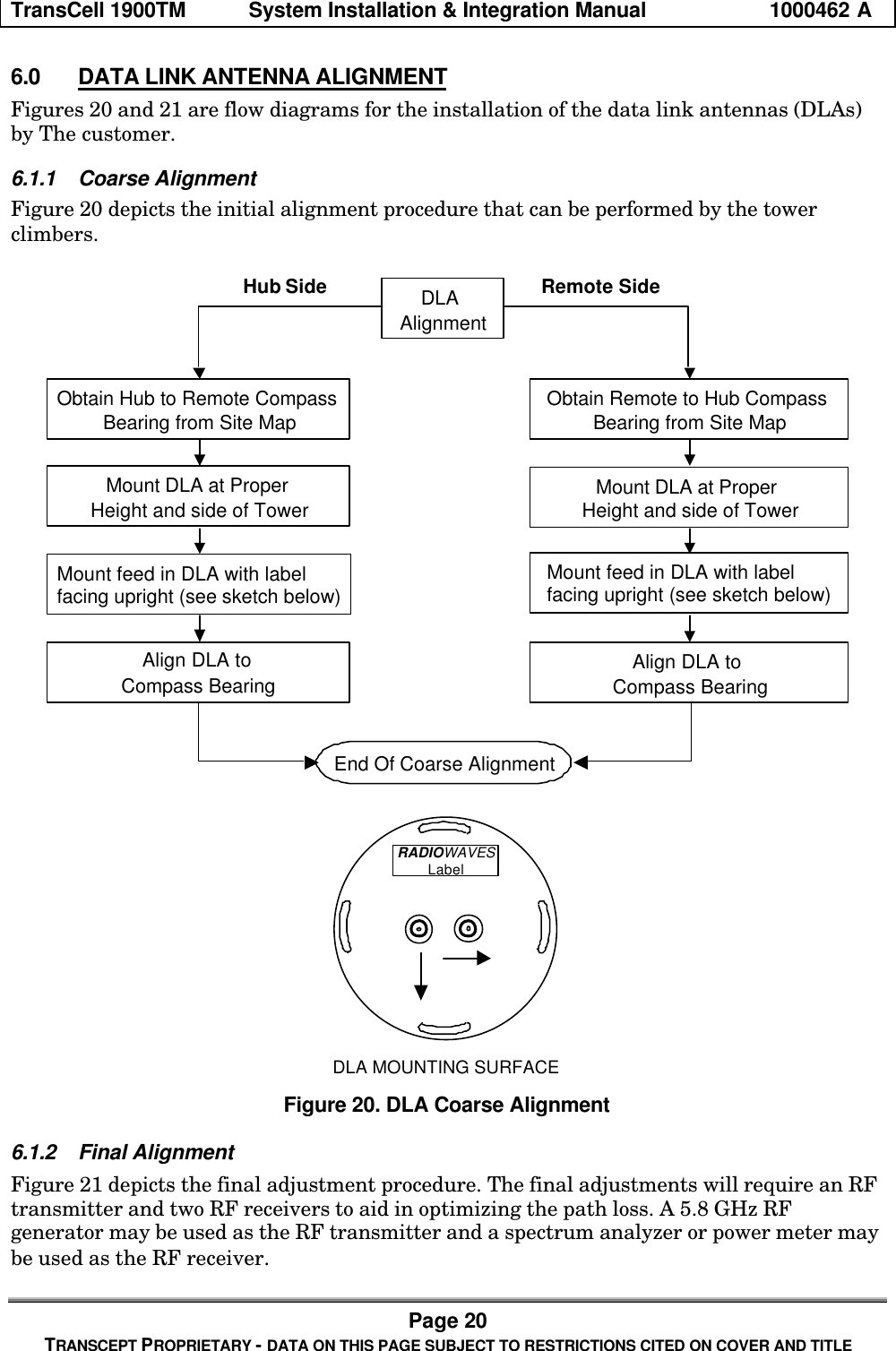

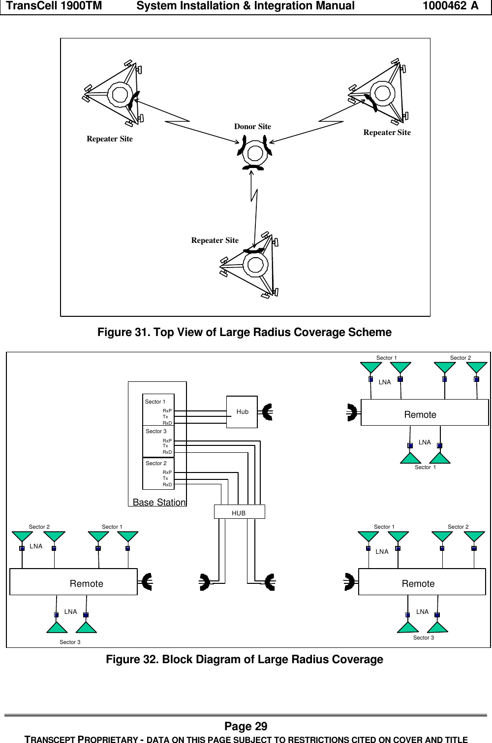
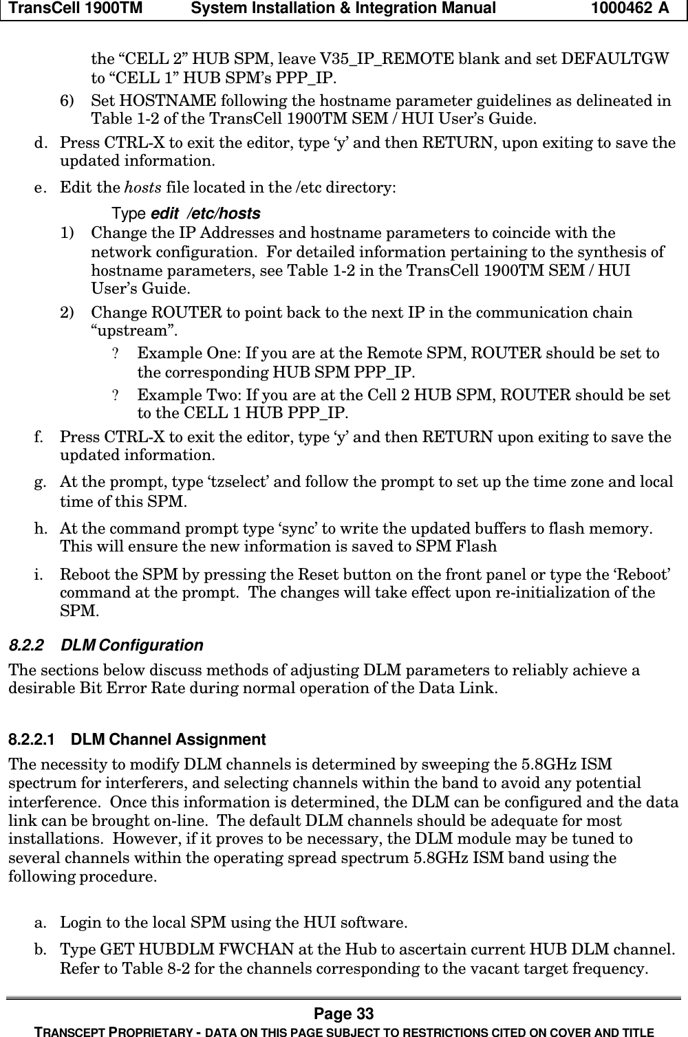
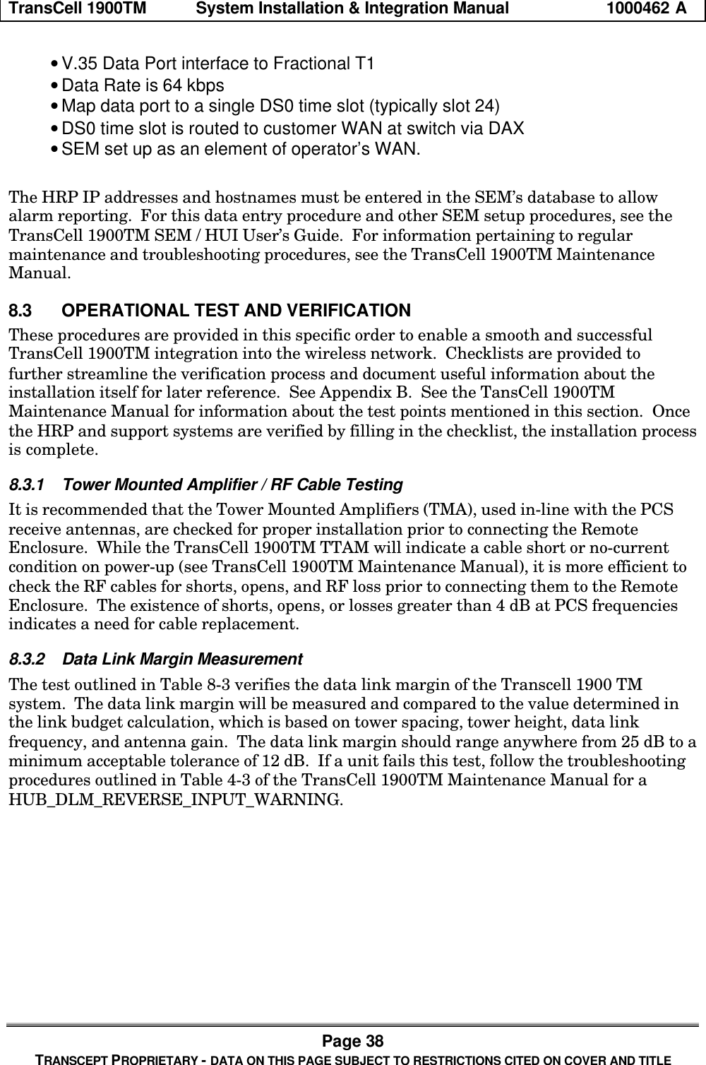
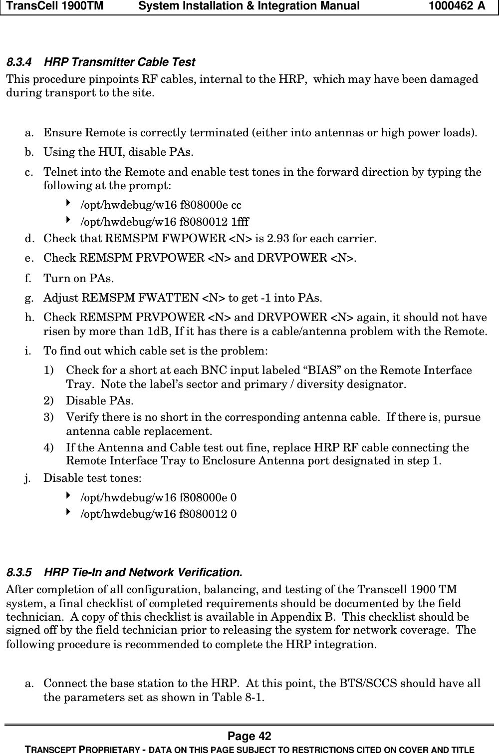
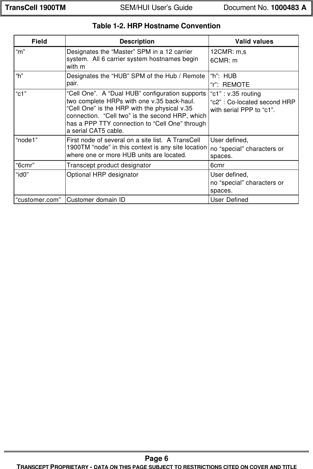
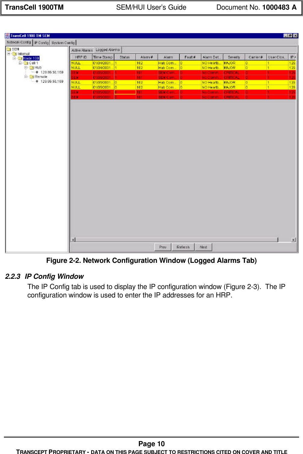
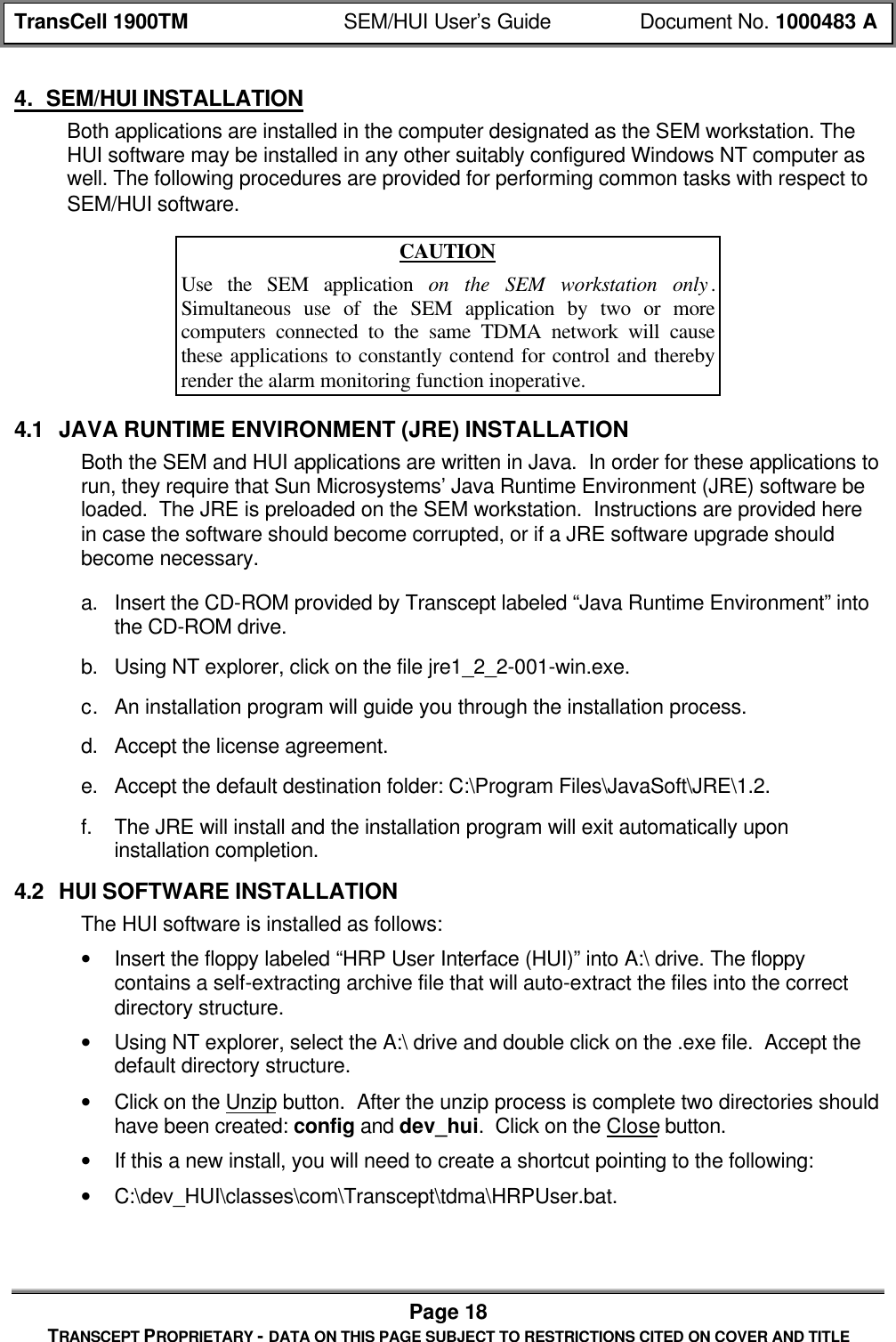
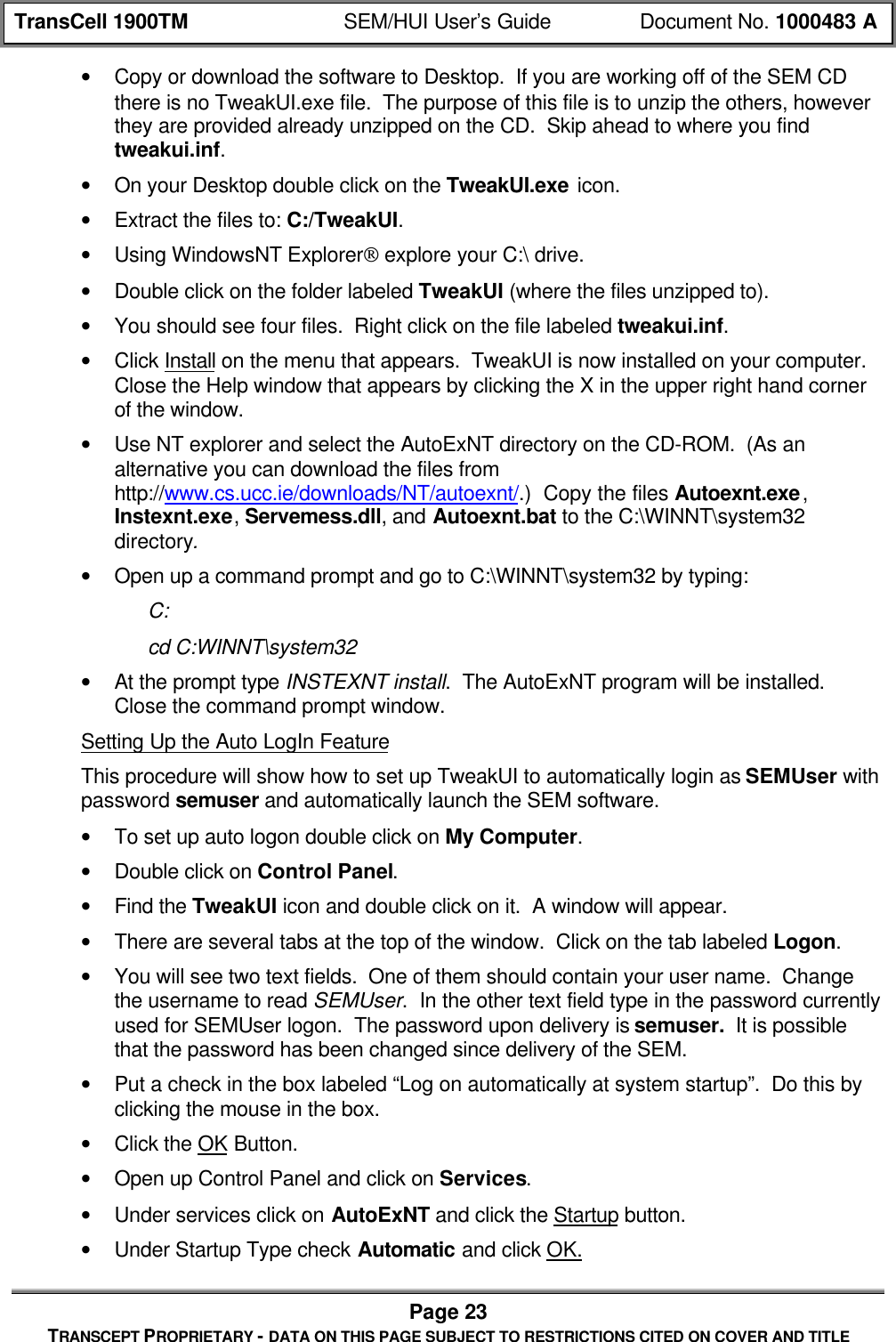
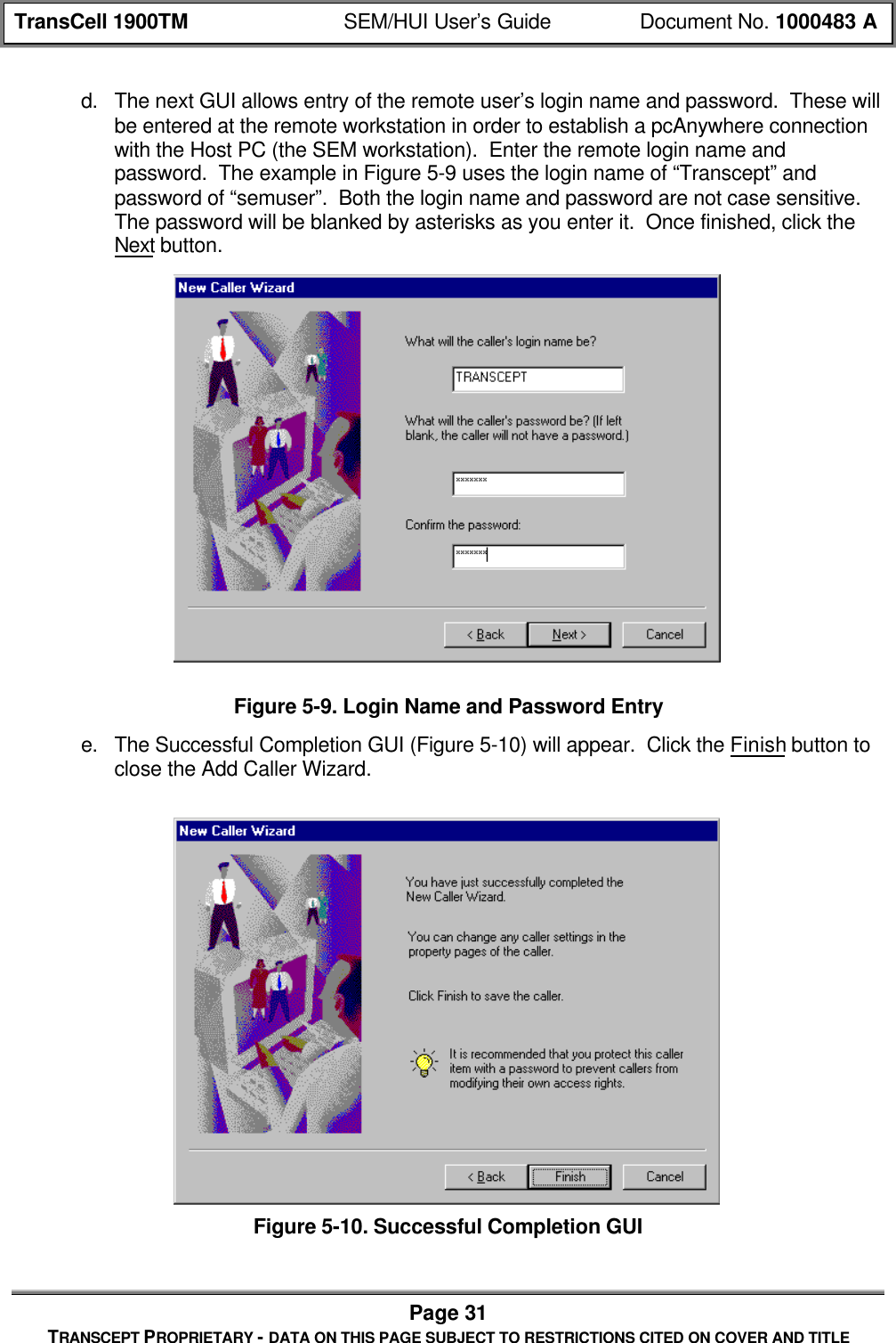
![TransCell 1900TM System Installation & Integration Manual 1000462 APage 37TRANSCEPT PROPRIETARY - DATA ON THIS PAGE SUBJECT TO RESTRICTIONS CITED ON COVER AND TITLETable 8-3. Default HRP Gain SettingsHUB Settings:HUI Command: Standard Configuration Settings:get hubspm fwgain [carrier # 1-6] 20get hubspm prvatten [carrier #1-6] 3 to 5(-43 dBm HTM output, given –51 dBminput at Remote Primary Receive Port)get hubspm drvatten [carrier #1-6] 3 to 5(-43 dBm HTM output, given –51 dBminput at Remote Diversity Receive Port)get htm prvatten [carrier #1-6]get htm drvatten [carrier #1-6]Remote Settings:HUI Command: Standard Configuration Settings:get remspm fwatten [carrier # 1-6] 5 to 15 (+48 dBm PA output power)get remspm prvgain [carrier # 1-6] 16get remspm drvgain [carrier # 1-6] 16get rtm prvgain [carrier #1-6]get rtm drvgain [carrier #1-6]8.2.4 Reverse Path Filter ConfigurationIf the TransCell 1900TM system is being integrated with a Lucent Base Station, then analternate set of reverse filters must to be loaded into the HRP to ensure normal operation.The extra 4 half-symbol delay introduced by Lucent base stations, when coupled with theTransCell 1900TM delay, can cause call origination problems when the Hub and Remoteare separated by 9 miles or more. The alternate filters trade signal rejection for speed, andtherefore degrade the TransCell 1900TM system’s interference susceptibility as outlined innote 6 of the Product Specification. Use the following procedure to change the digitalreceive filters.a. Determine the distance between HUB and Remote towers. If less than 9 miles, donot change the filters.b. Login to the HRP via the HUI and verify data-link lock.c. Type SET REMSPM RVFILTER ddcrmt63 and press ENTER.d. Verify data-link re-locks within ten seconds.8.2.5 OA&M Interface ConfigurationIn order to report alarming to the switch and System Element Manager (SEM) via TCP/IP,the Transcell 1900TM system requires access to the Base Station DSU/CSU installed ateach Donor site and configured with an external V.35 data port interface to the Hubequipment. This access is typically provided through the operator’s Wide Area Network(WAN). The general configuration is as follows:](https://usermanual.wiki/OpenCell/TCELL1900TM.Exhibit-D-users-manual/User-Guide-150591-Page-44.png)
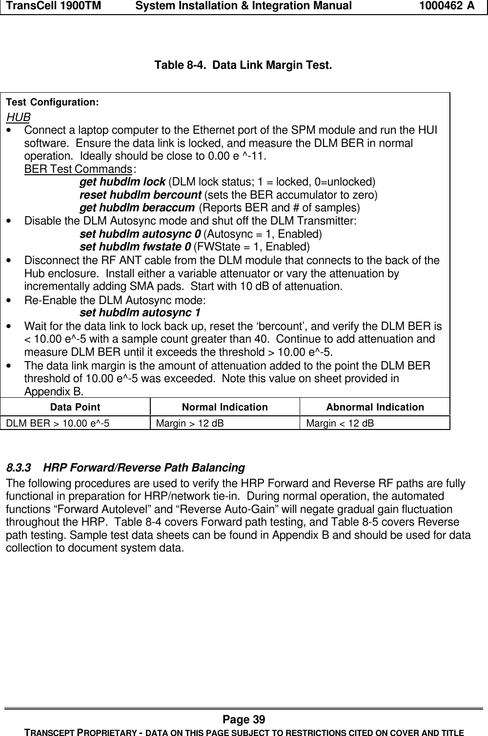
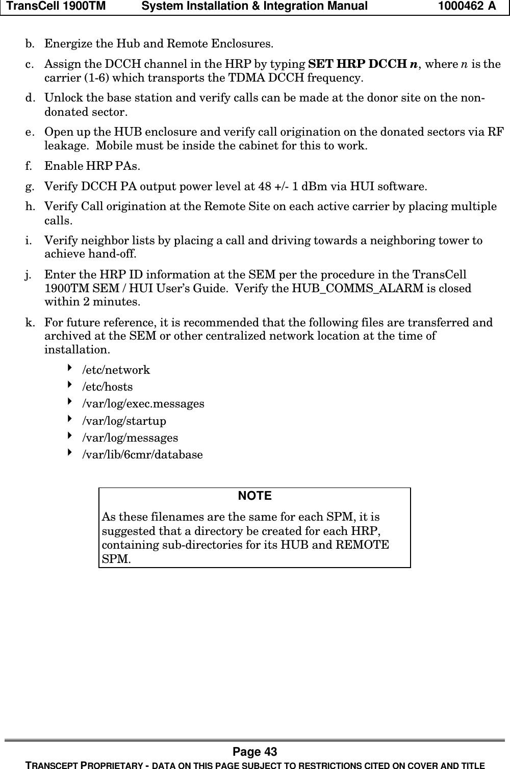


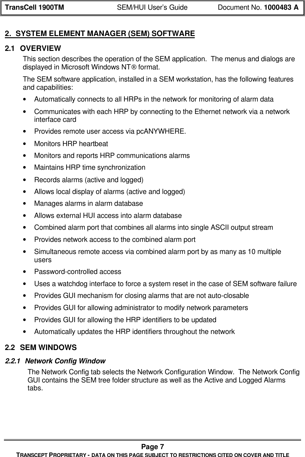
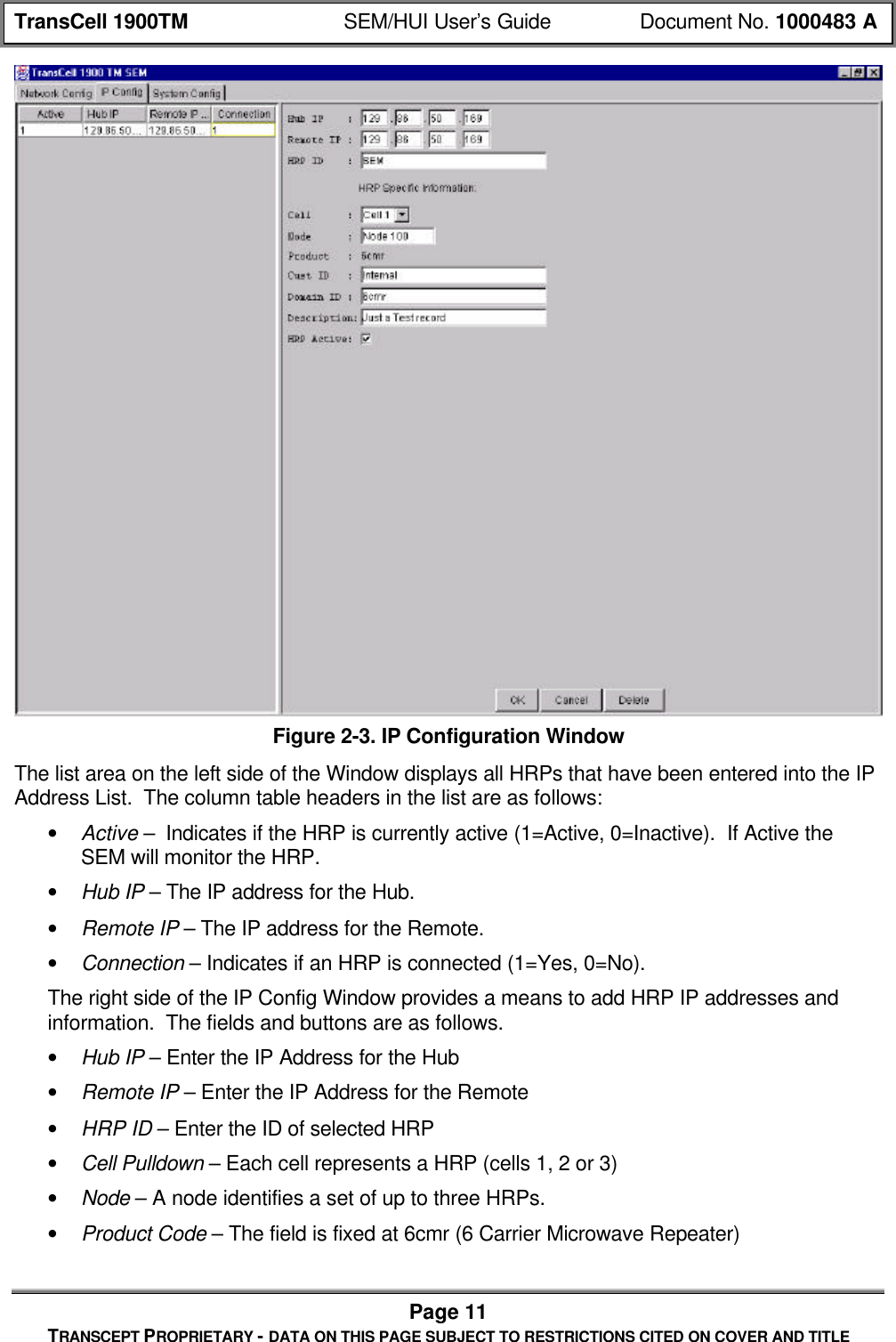
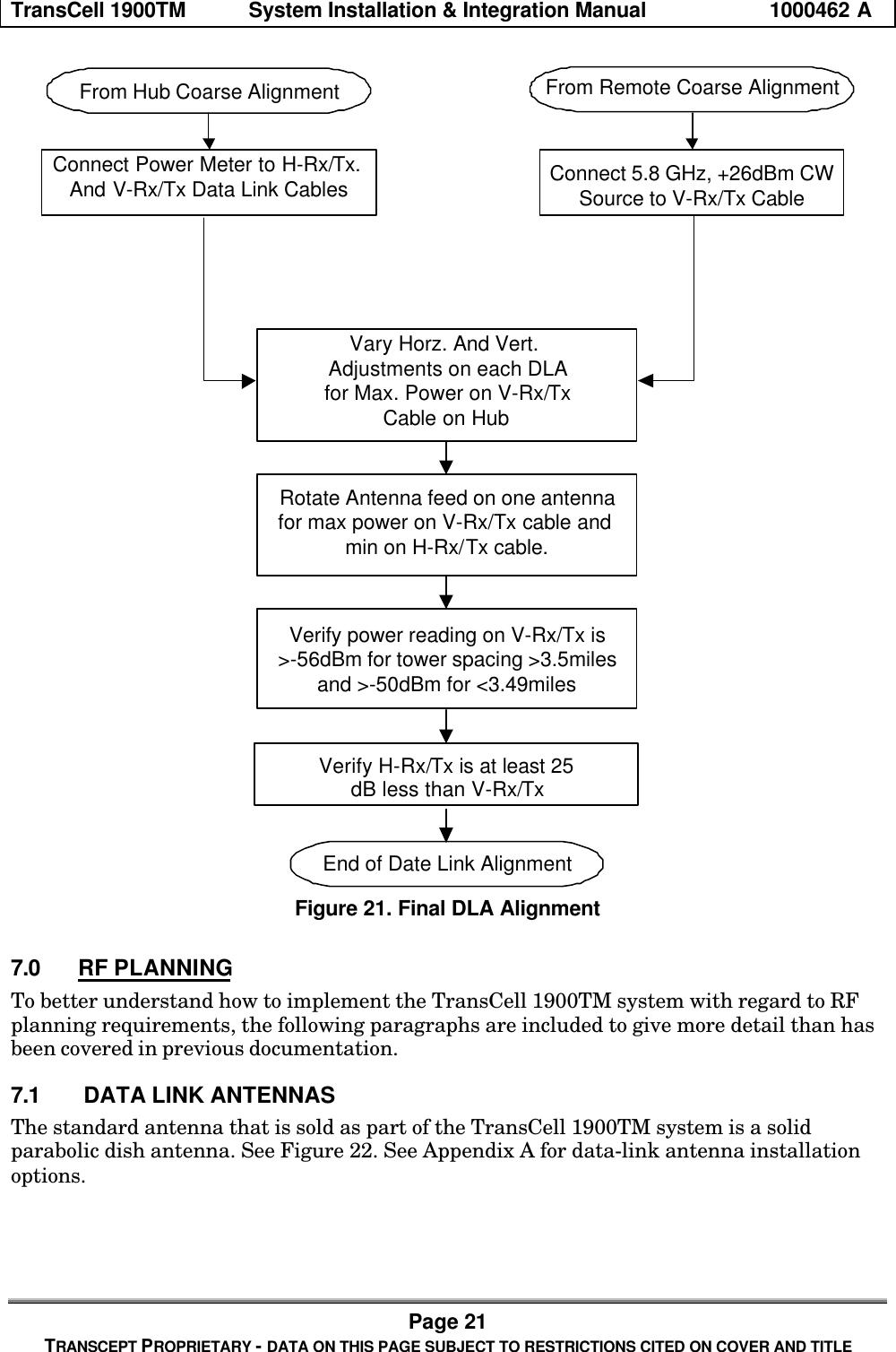
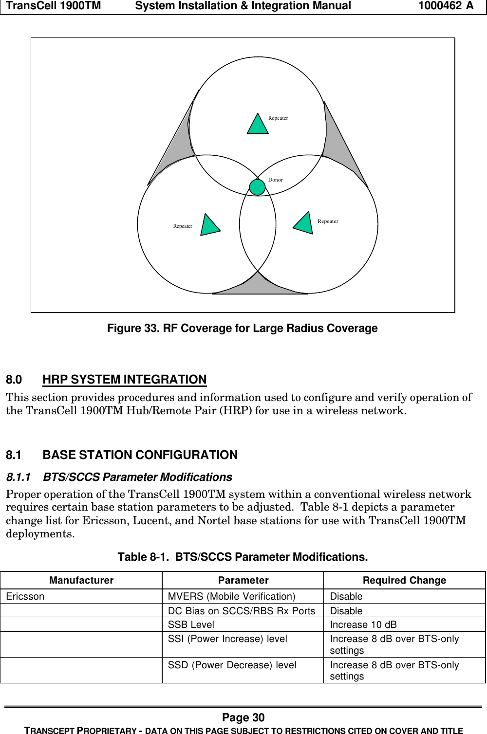
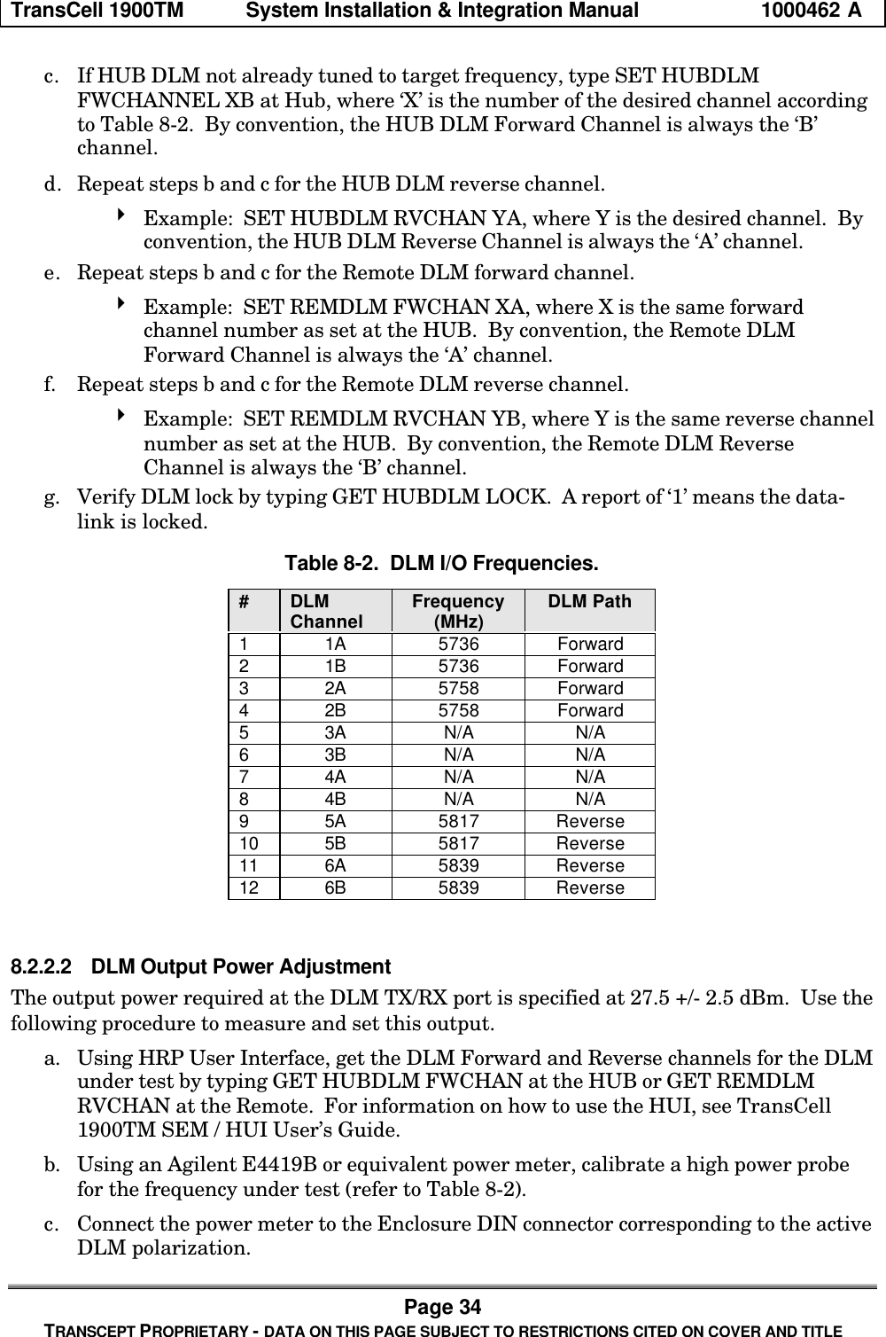
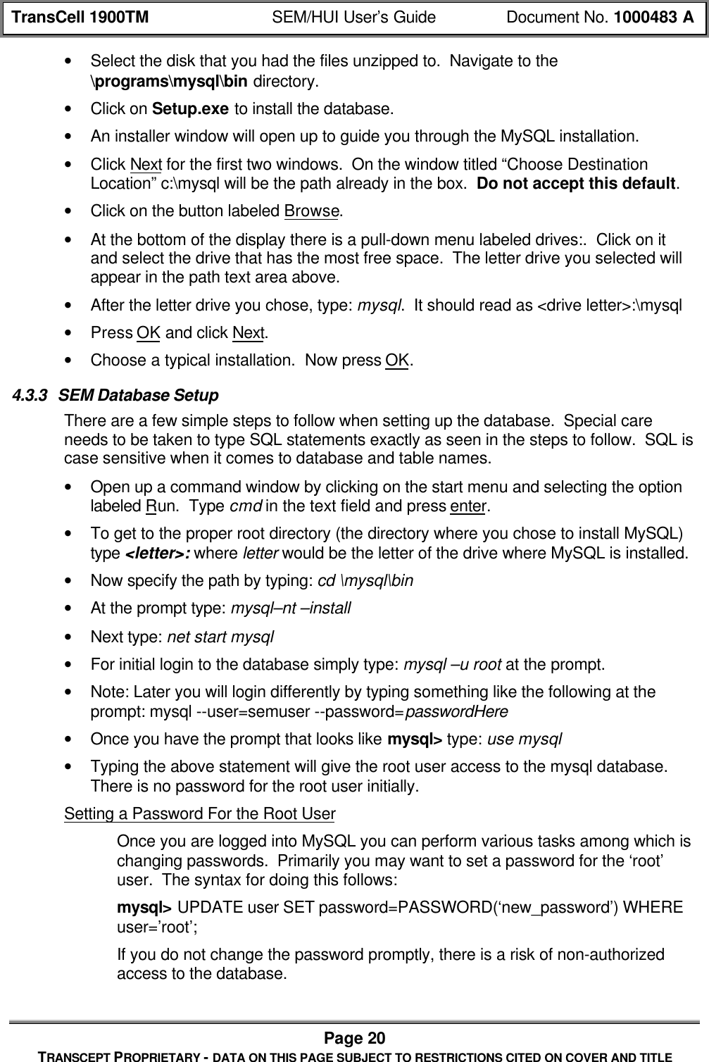
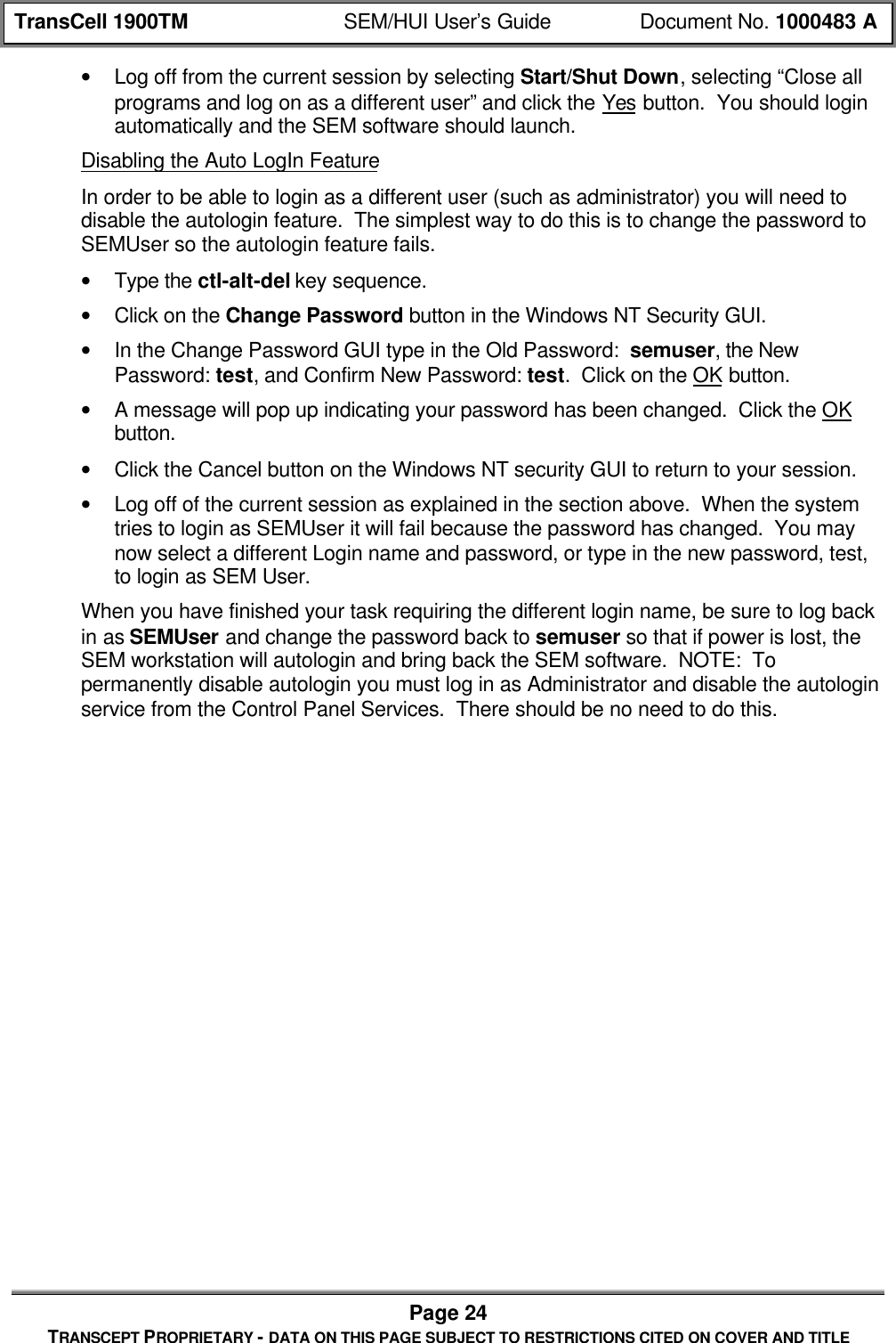
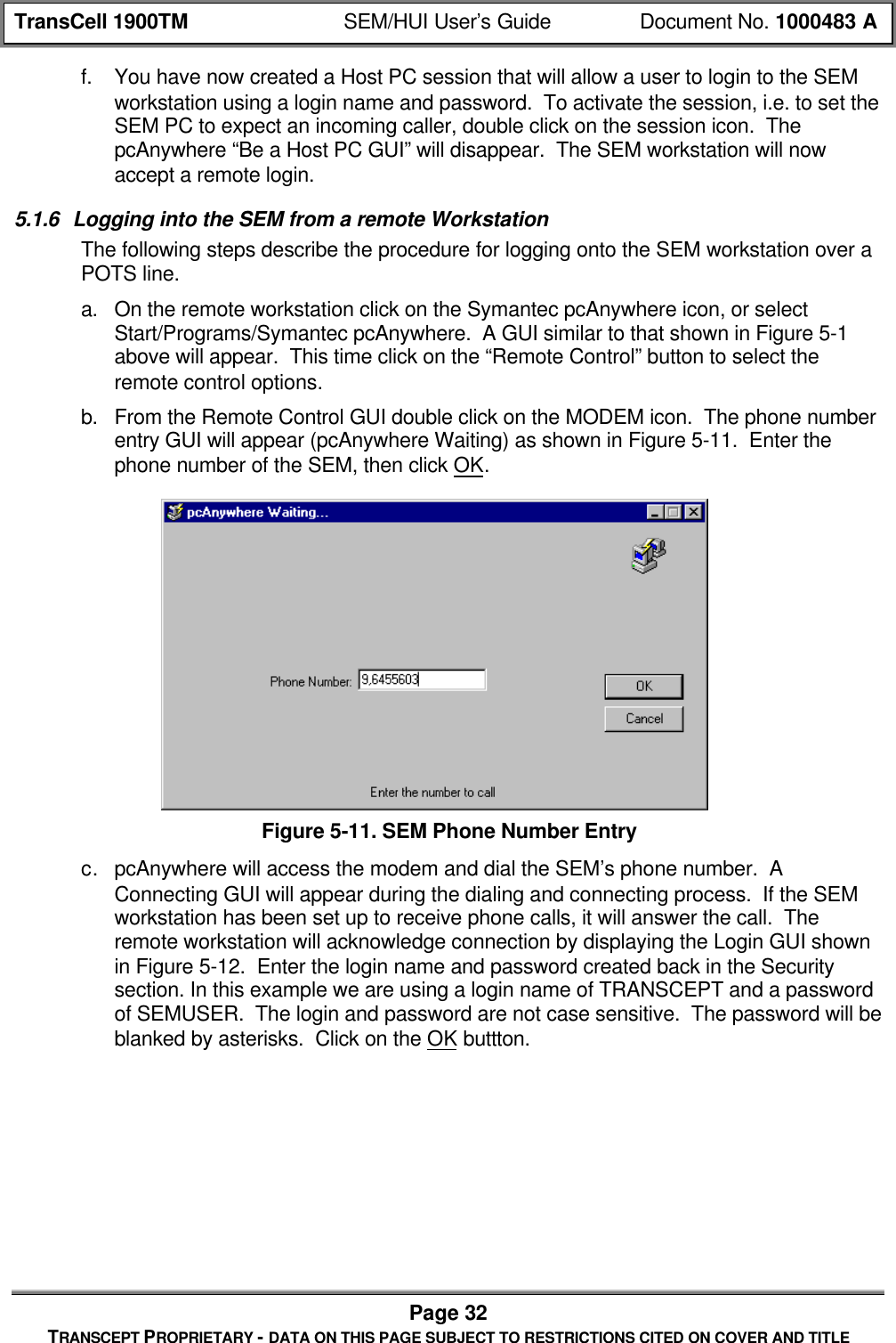
![TransCell 1900TM SEM/HUI User’s Guide Document No. 1000483 APage 19TRANSCEPT PROPRIETARY - DATA ON THIS PAGE SUBJECT TO RESTRICTIONS CITED ON COVER AND TITLE4.3 SEM SOFTWARE INSTALLATION4.3.1 SEM Application Software InstallationThe SEM software is provided by Transcept on a CD-ROM. If this is a first time install,you will have to set the CLASSPATH variables in order to run the class files.• Setting the CLASSPATH variables• To set the CLASSPATH, right click on MyComputer.• Choose properties from the pulldown.• Click on the Environment tab.• Type: CLASSPATH in the Variable text field.• In the Value text field type: .;c:\dev\mysql.jar;%CLASSPATH%. TheCLASSPATH lets the computer know where to look for java files associated withthe program that is running. In this instance we are telling it to look underc:\dev\mysql.jar. It is VERY important that the classpath be typed correctly. Itputs the starting directory in the classpath.• Click the Set button then click OK.• Insert the CD-ROM labeled “SYSTEM ELEMENT MANAGER” into the CD-ROMdrive.• Using NT Explorer, select the CD-ROM drive. There should be a folder labeled devon the CD.• Click and drag the folder labeled dev from the CD-ROM onto the [C:]• If this a new install, you will need to create shortcuts pointing to the following batchfiles: C:\dev\SEM.bat, C:\dev\Watchdog.bat, and C:\dev\DatabaseBackup.bat.• If this a new install, you will also need to put the c:\dev directory on the SEMworkstation’s path. To do this you must have administrator privileges. Right click onMy Computer and select Properties. Select the environment tab. In the SystemVariables area find and select path. In the Value box hit the right arrow key to go tothe end of the line. Then type: ;c:\dev and hit the Set button. Then hit the Applybutton followed by the OK button.4.3.2 SEM Database Software InstallationThe SEM software uses a MySQL database to store and process alarm data. Thereforethe MySQL database must be installed prior to using the SEM.The SEM workstation comes ready with the database installed. If for some reason youneed to reinstall the database follow the instructions below.• Insert the CD-ROM labeled “MYSQL DATABASE” into the CD-ROM drive.• Using NT Explorer, select the CD-ROM drive.• Double click on the MySQLselfExtract.exe file. The contents will be put intoD:\programs\mysql\bin by default if you choose not to specify a different drive. Selectthe disk drive that has the most free space on it. Click on the Unzip button.• Click on the Close button.](https://usermanual.wiki/OpenCell/TCELL1900TM.Exhibit-D-users-manual/User-Guide-150591-Page-80.png)
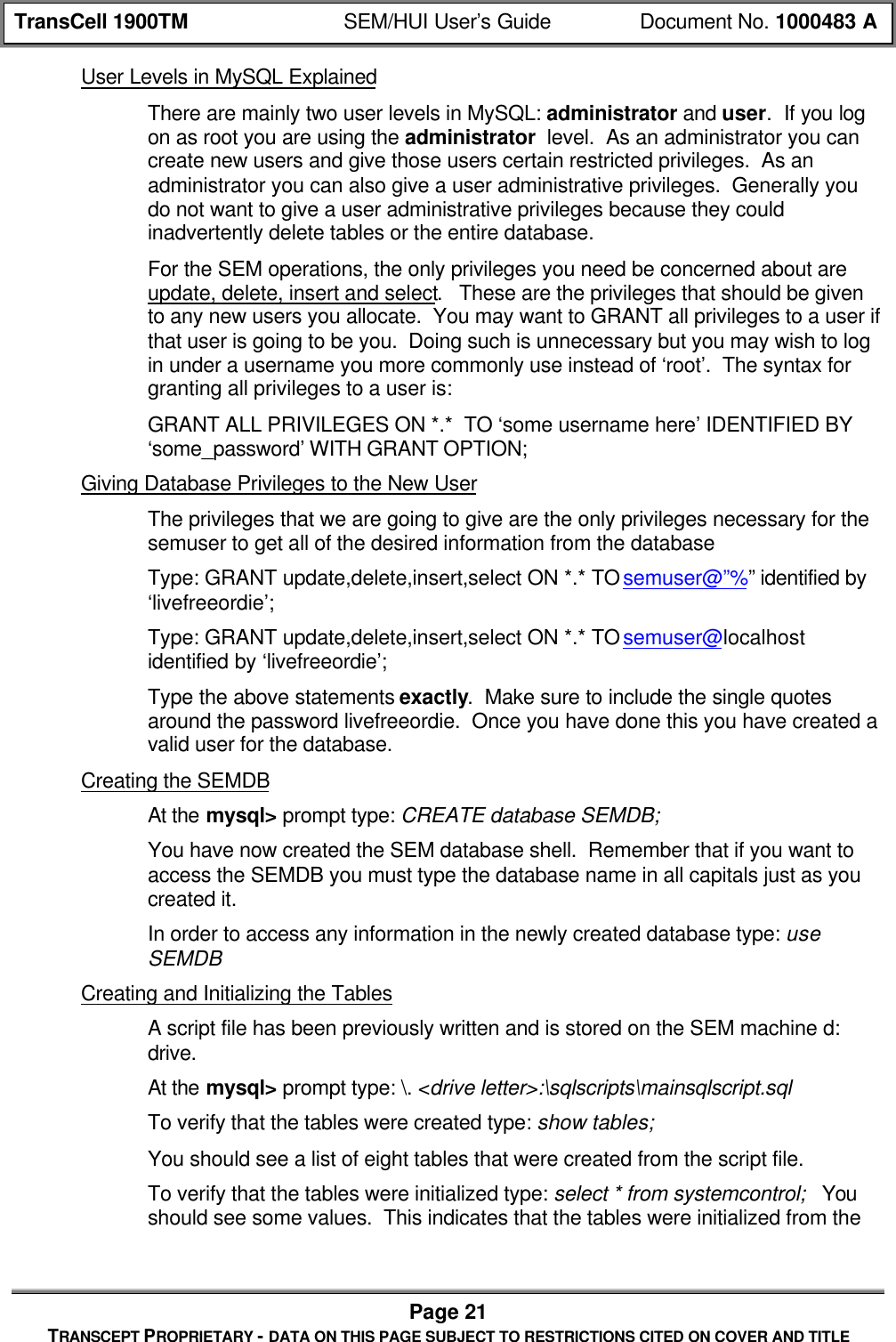
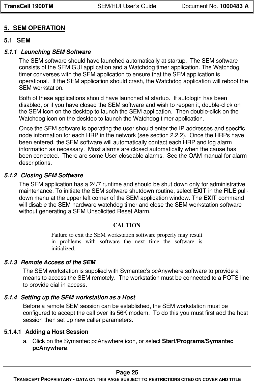
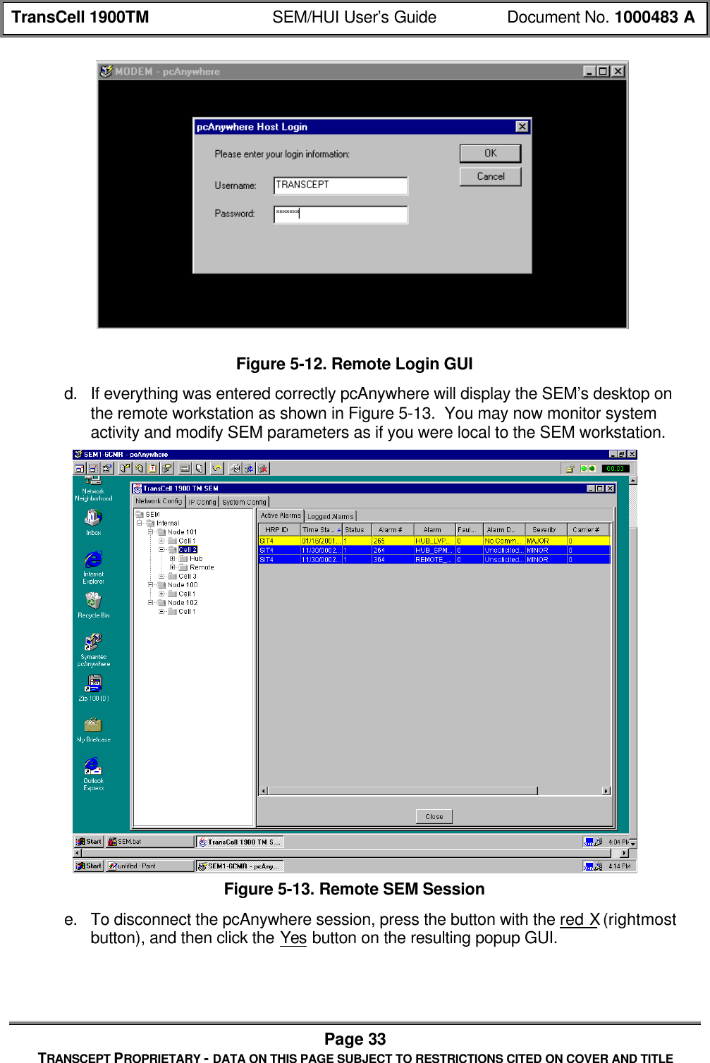

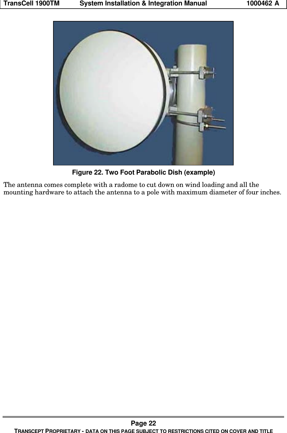
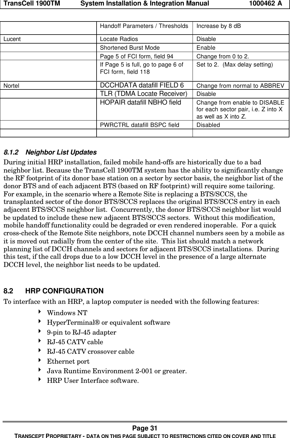
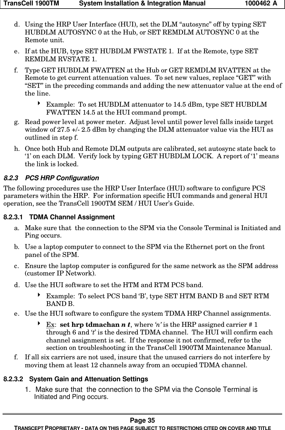
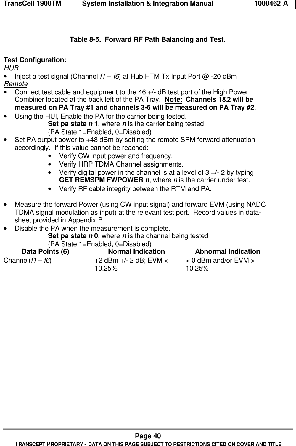
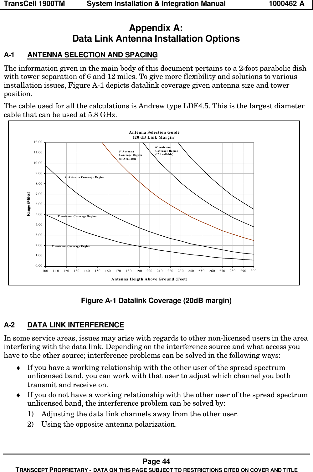
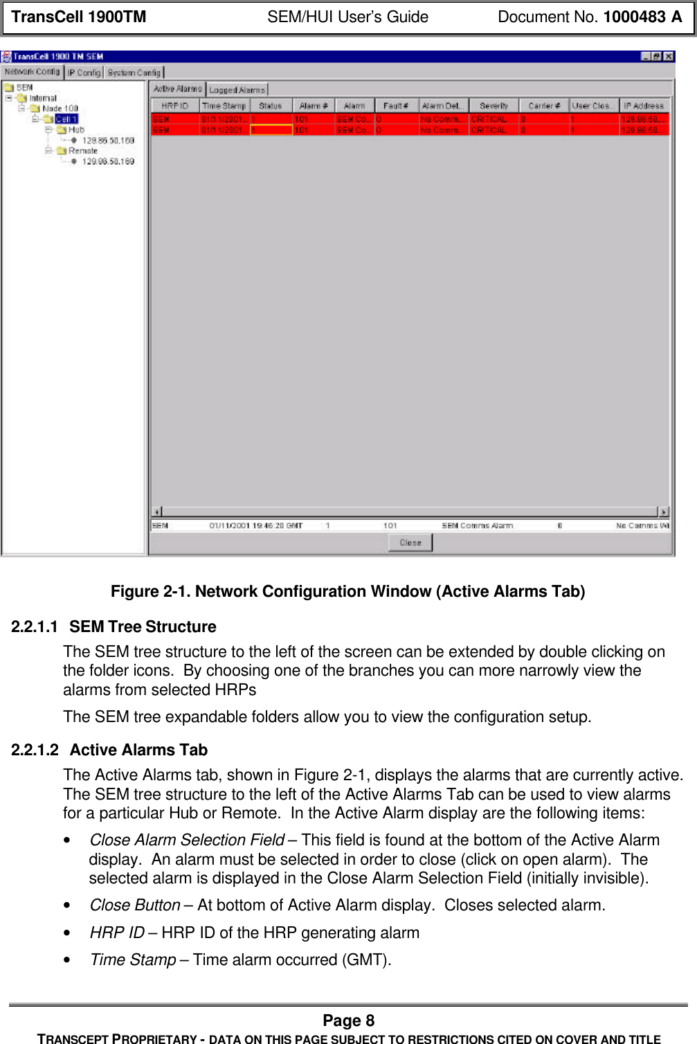
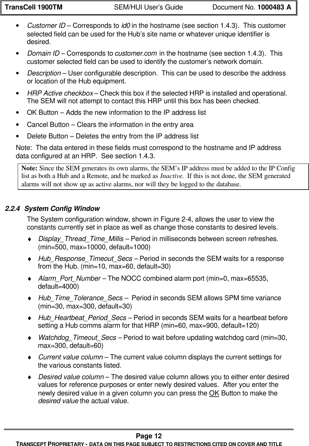
![TransCell 1900TM SEM/HUI User’s Guide Document No. 1000483 APage 43TRANSCEPT PROPRIETARY - DATA ON THIS PAGE SUBJECT TO RESTRICTIONS CITED ON COVER AND TITLE• HRP Identifier – 1 to 31 characters; user defined identifier; used in alarm reporting• PA Enable State - Select by Remote Transceiver Module (RTM) number• Attenuators – Forward; primary/diversity reverse; settable at HTM, RTM orHub/Remote level; digital attenuatorsThe following describes the format of this message type:• [HEADER]• "SET"• [DEVICE]• [PARAM]• [CARRIER] (possible, depends on parameter)• [VALUE] (possible, depends on parameter)• [MISC] (possible, depends on parameter)• [EOM]The response to this message by the SPM will contain the request message with eithera "CONFIRM" or "NACK" field being inserted as the first field. In the case of themessage being NACKed, the [ERROR] field will contain the error code(s) explaining whythe message could not be processed. The following is the response template:If command successful: [HEADER] CONFIRM: [ECHO OF REQUEST MESSAGE]If command unsuccessful: [HEADER] NACK: [ERROR]The following table defines the valid devices, parameters, carriers, and values that areallowed in the SET message. There is also a secondary field called “Misc” for anyadditional data. This field is displayed in the table below only if it is needed (it will alsoappear shaded):Table 7-1. CLI Set CommandsDevice Parameter Carrier Value Misc DescriptionHRP TDMACHAN 1 – 6 2 – 1998 (overall,limited by band) Sets the HTM and RTM Channel andUpdates the DDC/DUC FrequenciesHRP DCCH 1 – 6 Sets the DCCH on the Hub and RemoteHRP ALMSTATE XXX Y XXX = Alarm Number, Y = 0/1 (off/on)LOCALSPM GENDER HUB or REMOTE Sets the Gender of this SPMLOCALSPM TIME 0 – 232 Set Time (Seconds since 1/1/1970) onthis SPMLOCALSPM ID 1 – 31 chars Sets the HRP ID of this SPMLOCALSPM DCCH 1 – 6 Sets the DCCH Carrier of this SPMLOCALSPM SHUTDOWN Causes this Executive to ShutdownHUBSPM TIME 0 – 232 Set time (Seconds since 1/1/1970) onHub SPMHUBSPM ID 1 – 31 chars Sets the ID of the Hub SPMHUBSPM DCCH 1 – 6 Sets the DCCH on the Hub SPMHUBSPM REGISTER Xxxxxxxx yyyy 32-bit Address/16-bit Word to Write](https://usermanual.wiki/OpenCell/TCELL1900TM.Exhibit-D-users-manual/User-Guide-150591-Page-104.png)
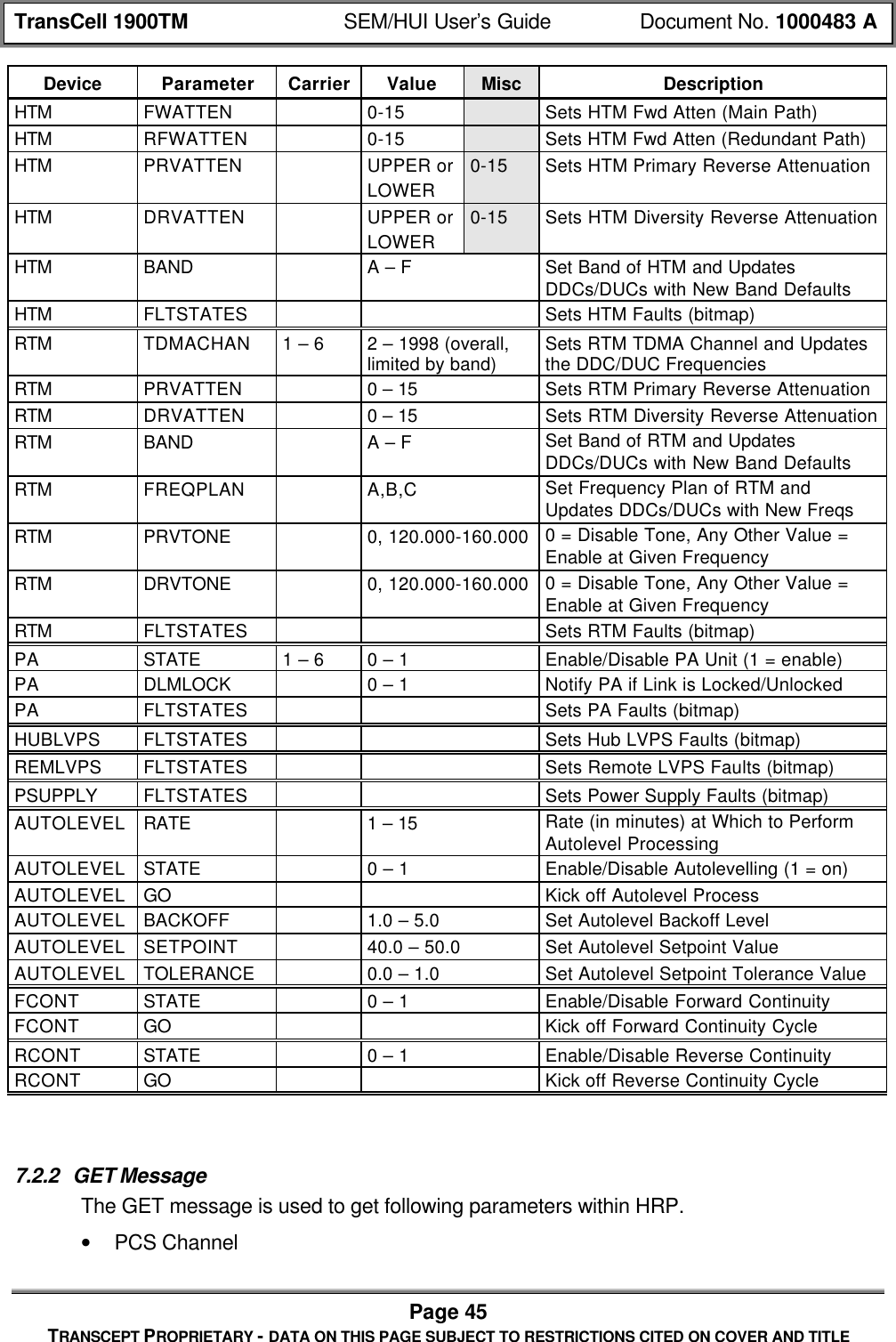
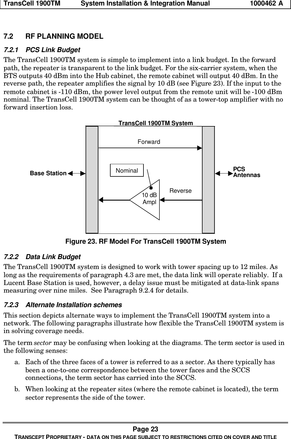
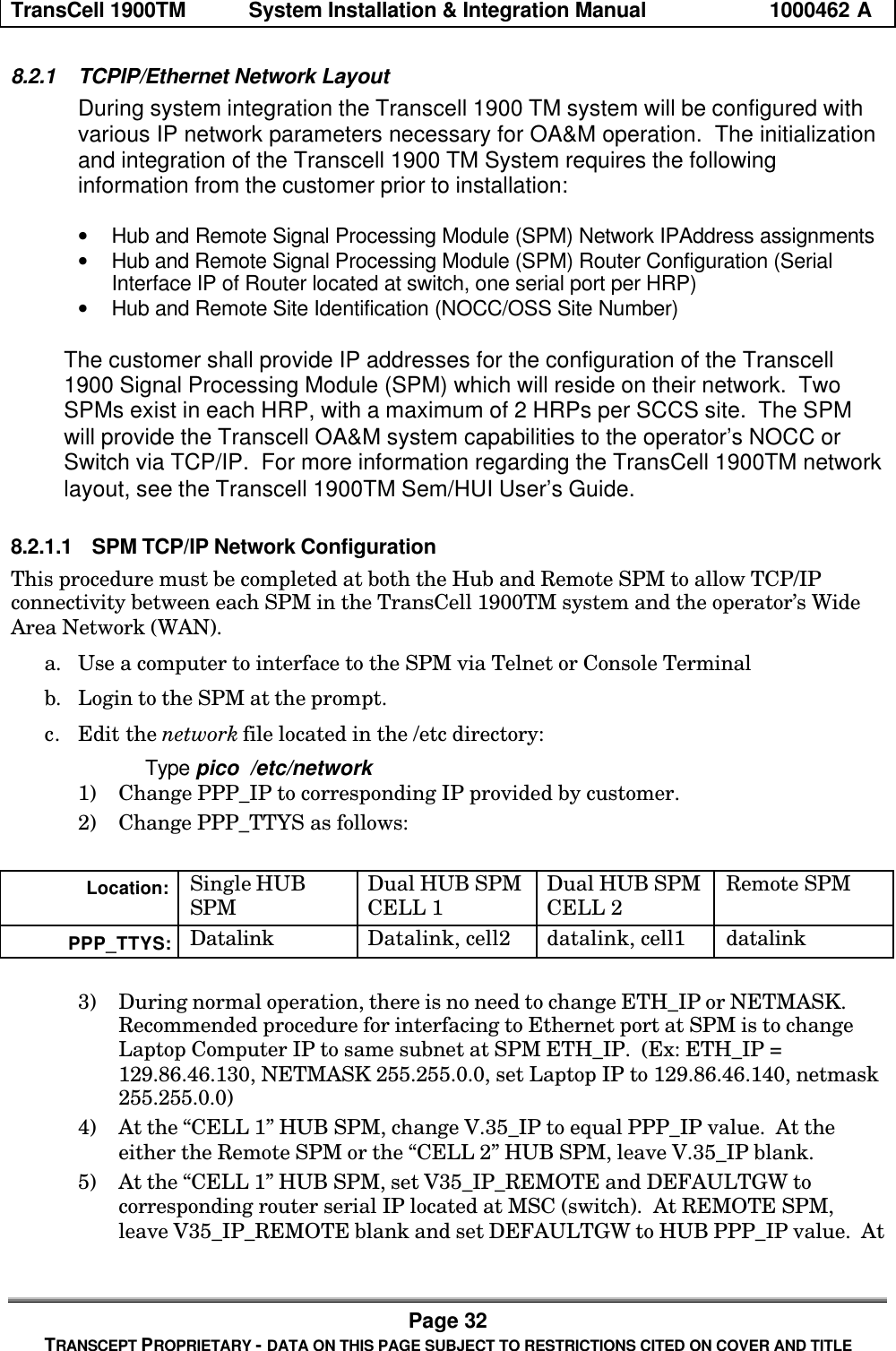
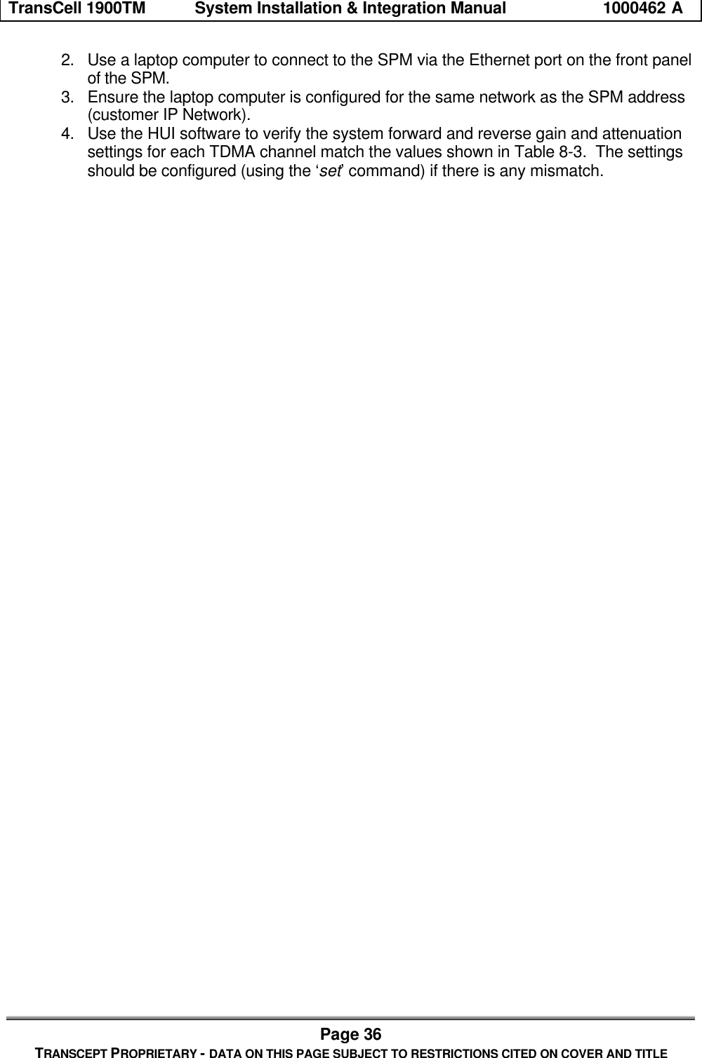
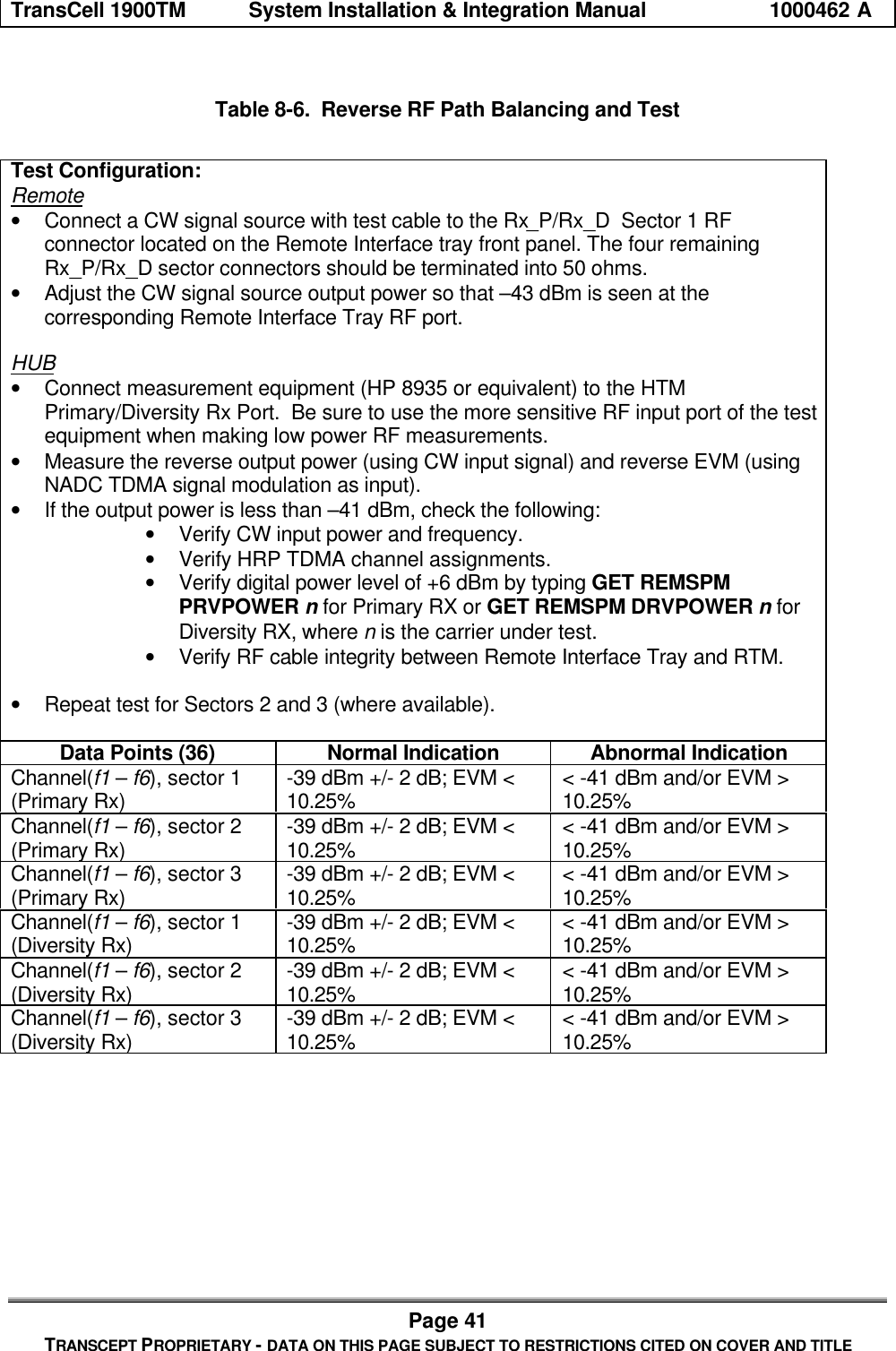
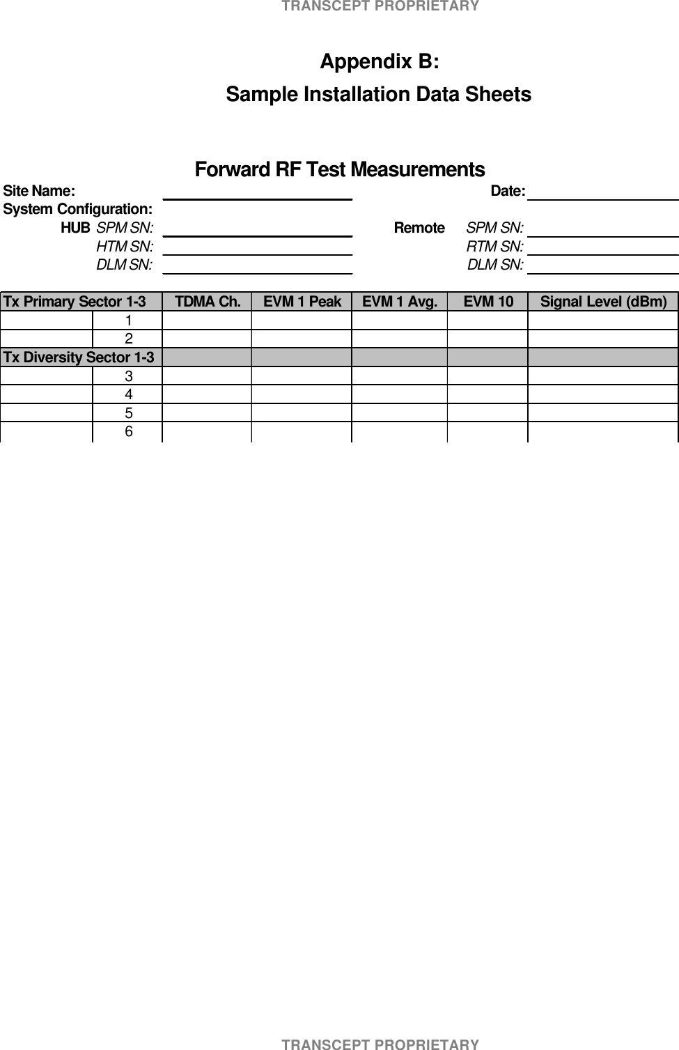
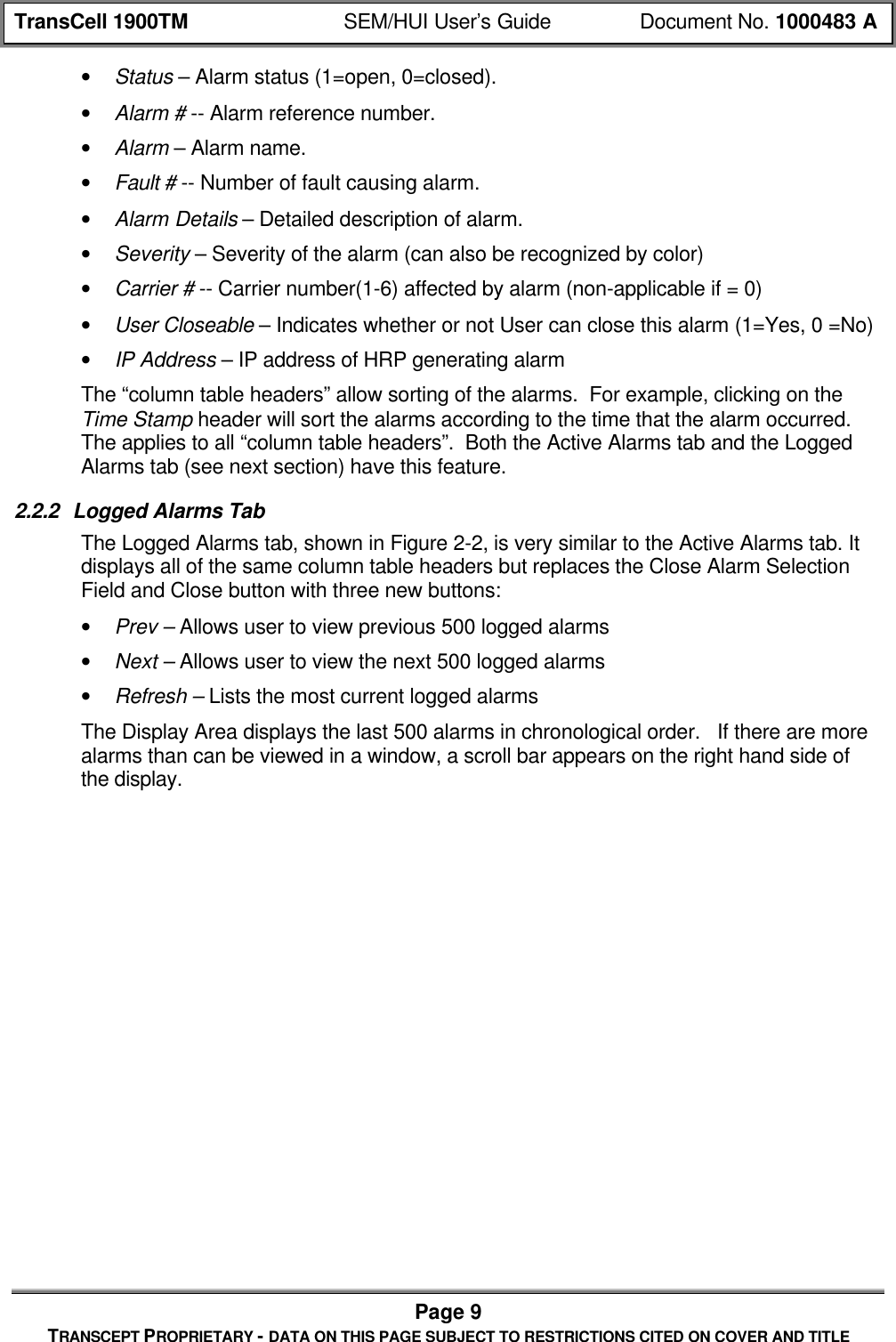
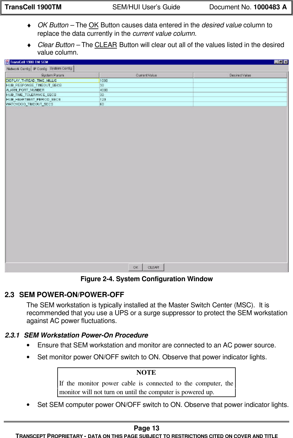
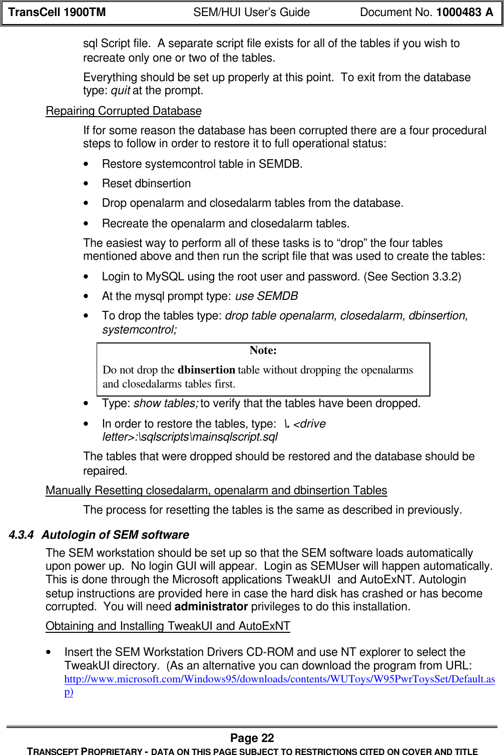
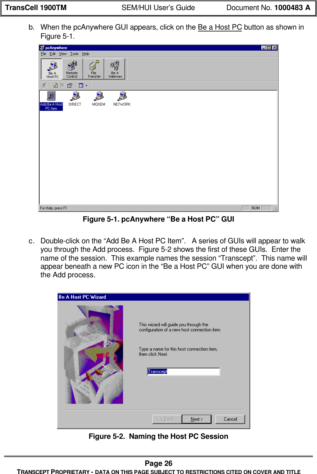
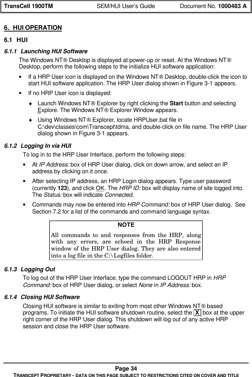
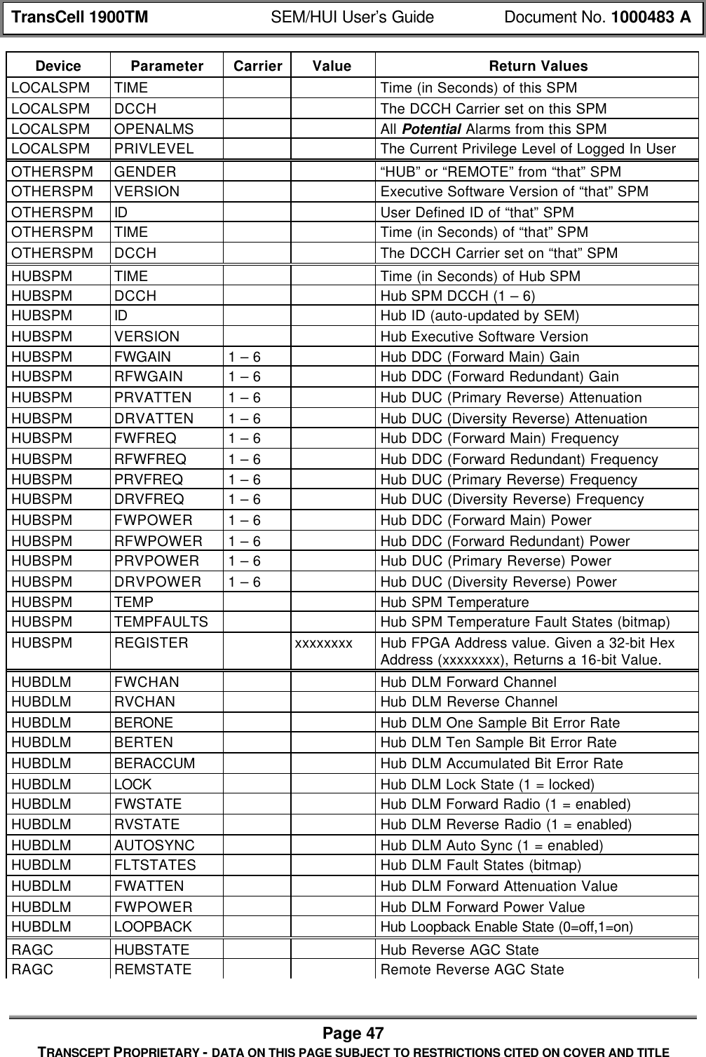
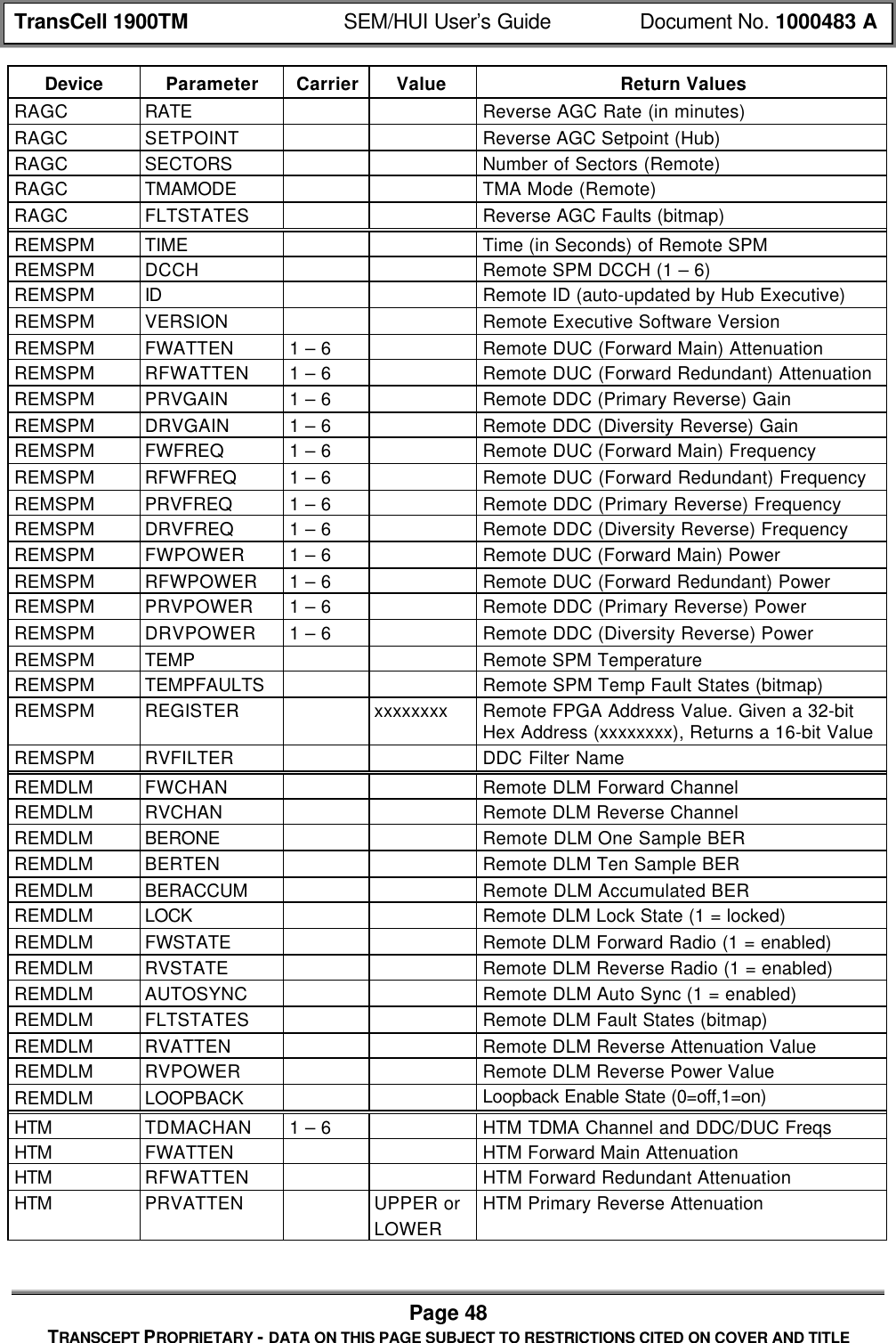
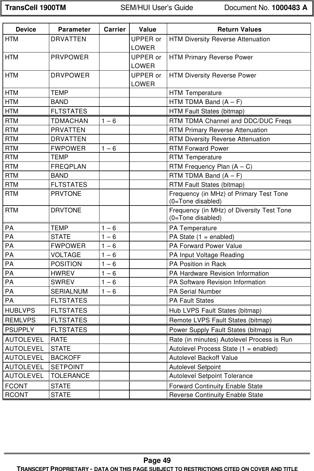
![TransCell 1900TM SEM/HUI User’s Guide Document No. 1000483 APage 46TRANSCEPT PROPRIETARY - DATA ON THIS PAGE SUBJECT TO RESTRICTIONS CITED ON COVER AND TITLE• Data Link Channel – forward/reverse channel, lock state, Bit Error Rate• Alarm Enable States• HRP Identifier• Temperature Values – HTM, RTM (Fwd, Rev, PA)• Attenuator Power Values – Forward; primary/diversity reverse; request at a HTM,RTM, Hub/Remote level; digital attenuators• Software Revisions – HTM, RTM, SPM• PA – State (on/off); power The following describes the format of this message type:• [HEADER]• "GET"• [DEVICE]• [PARAM]• [CARRIER] (possible, depends on parameter)• [VALUE] (possible, depends on parameter)• [EOM]The return message type will be one of two types: either "REPORT" if successful or"NACK" if unsuccessful. In the case of a "REPORT" return, the return value(s) will beindicated in the [VALUE] field. In the case of a "NACK" return (either because of aninvalid request format or some other processing reason), the error code(s) will beindicated in the [ERROR] field. The return message will take on the following form:If command successful: [HEADER] REPORT: [VALUE]If command unsuccessful: [HEADER] NACK: [ERROR]For some cases of successful “GET LOCALSPM” type commands, the response formatwill be slightly modified to accommodate the HUI software:[HEADER] REPORT [PARAM]: [VALUE]The following table defines the valid devices, parameters, indices, and values that areallowed in the GET message:Table 7-2. CLI Get CommandsDevice Parameter Carrier Value Return ValuesHRP TDMACHAN 1 – 6 TDMA Channel – Validation is Done to be Surethat Both Sides are SynchedHRP DCCH System DCCH – Validation is Done to be Surethat Both Sides are SynchedHRP ALMSTATE XYZ HRP Alarm State (1 = on) Corresponding toAlarm Number XYZLOCALSPM GENDER "HUB" or "REMOTE" from this SPMLOCALSPM VERSION Executive Software Version of this SPMLOCALSPM ID User Defined ID of this SPM](https://usermanual.wiki/OpenCell/TCELL1900TM.Exhibit-D-users-manual/User-Guide-150591-Page-107.png)
![TransCell 1900TM SEM/HUI User’s Guide Document No. 1000483 APage 50TRANSCEPT PROPRIETARY - DATA ON THIS PAGE SUBJECT TO RESTRICTIONS CITED ON COVER AND TITLE7.2.3 RESET MessageThis message is used to reset a given device. This request from the user will take on thefollowing form:• [HEADER]• "RESET"• [DEVICE]• [PARAM]• [CARRIER] (possible, depends on device)• [EOM]The following table defines the valid devices, parameters, indices, and values that areallowed in the RESET message:Table 7-3. CLI Reset CommandsDevice Parameter CarrierHUBSPM FWPATHHUBSPM RVPATHHUBDLM DEVICEHUBDLM BERCOUNTREMSPM FWPATHREMSPM RVPATHREMDLM DEVICEREMDLM BERCOUNTHTMRTMPA 1 – 6TTAAUTOLEVEL BACKOFFIn this message, FWPATH, PRVPATH, and DRVPATH on either the HUB-side orREMOTE-side SPM refers to the resetting of the DDCs and DUCs.The AUTOLEVEL BACKOFF reset command will override the one-time autoleveladjustment.The response to this message by the SPM will contain the request message with eithera "CONFIRM" or "NACK" field being inserted as the first field. In the case of themessage being NACKed, the [ERROR] field will contain the error code(s) explaining whythe message could not be processed. The following is the response template:If command successful: [HEADER] CONFIRM: [ECHO OF REQUEST MESSAGE]If command unsuccessful: [HEADER] NACK: [ERROR]](https://usermanual.wiki/OpenCell/TCELL1900TM.Exhibit-D-users-manual/User-Guide-150591-Page-111.png)
![TransCell 1900TM SEM/HUI User’s Guide Document No. 1000483 APage 51TRANSCEPT PROPRIETARY - DATA ON THIS PAGE SUBJECT TO RESTRICTIONS CITED ON COVER AND TITLE7.2.4 LOGIN MessageThis message is used to allow the user to log in to the HUI. The software design requiresthat a user be logged in before being allowed to monitor and control the system. (Theonly exception to this is the use of certain “GET LOCALSPM” type messages). The userwill enter a password in the [VALUE] field. The LOGIN request will take on the followingform:• [HEADER]• "LOGIN"• "LOCALSPM"• [VALUE]• [EOM]The VALUE field will contain the password, which will be hard-coded in the SPM, somealphanumeric string of 6 to 8 characters. There are currently two passwords allowed:one which allows for “read-only” access and one which allows for “read-write” access.The response to this message by the SPM will contain the request message with eithera "CONFIRM" or "NACK" field being inserted as the first field. In the case of themessage being NACKed, the [ERROR] field will contain the error code(s) explaining whythe message could not be processed. The following is the response template:If command successful: [HEADER] CONFIRM: [ECHO OF REQUEST MESSAGE]If command unsuccessful: [HEADER] NACK LOGIN: [ERROR]7.2.5 LOGOUT MessageThis message is used to log-out of the HRP. This command allows the SPM software toreset the communications port and configure it to listen for a new LOGIN message. Theform of this message will be as follows:• [HEADER]• "LOGOUT"• "LOCALSPM"• [EOM]The response to this message by the SPM will contain the request message with eithera "CONFIRM" or "NACK" field being inserted as the first field. In the case of themessage being NACKed, the [ERROR] field will contain the error code(s) explaining whythe message could not be processed. The following is the response template:If command successful: [HEADER] CONFIRM: [ECHO OF REQUEST MESSAGE]If command unsuccessful: [HEADER] NACK LOGOUT: [ERROR]7.2.6 CLOSE MessageThis message is used to allow the closing of alarms designated as “user-closeable”. Theform of this message is as follows, where the [VALUE] field contains the alarm ID andthe [MISC] field contains the fault ID:• [HEADER]](https://usermanual.wiki/OpenCell/TCELL1900TM.Exhibit-D-users-manual/User-Guide-150591-Page-112.png)
![TransCell 1900TM SEM/HUI User’s Guide Document No. 1000483 APage 52TRANSCEPT PROPRIETARY - DATA ON THIS PAGE SUBJECT TO RESTRICTIONS CITED ON COVER AND TITLE• "CLOSE"• "HRP"• “ALARM”• [VALUE]• [MISC]• [EOM]The response to this message by the SPM will contain the request message with eithera "CONFIRM" or "NACK" field being inserted as the first field. In the case of themessage being NACKed, the [ERROR] field will contain the error code(s) explaining whythe message could not be processed. The following is the response template:If command successful: [HEADER] CONFIRM: [ECHO OF REQUEST MESSAGE]If command unsuccessful: [HEADER] NACK: [ERROR]7.2.7 WRITE MessageThis message is used to write the logs that are stored in SPM RAM out to SPM flash. Itis not desirable to do this on a persistent basis, as the flash units can only handle alimited amount of writes. The form of this message is as follows, where the [VALUE] fieldcontains the alarm ID:• [HEADER]• "WRITE"• "LOCALSPM"• [PARAM]• [EOM]Currently, the only allowed parameter is “CMDLOG”, which is a log that stores allmessages sent from/to the HUI to/from the Executive software in the SPM.The response to this message by the SPM will contain the request message with eithera "CONFIRM" or "NACK" field being inserted as the first field. In the case of themessage being NACKed, the [ERROR] field will contain the error code(s) explaining whythe message could not be processed. The following is the response template:If command successful: [HEADER] CONFIRM: [ECHO OF REQUEST MESSAGE]If command unsuccessful: [HEADER] NACK: [ERROR]](https://usermanual.wiki/OpenCell/TCELL1900TM.Exhibit-D-users-manual/User-Guide-150591-Page-113.png)