OpenCell TCELL1900TM TransCell 1900TM User Manual O M Manual 1000497A
OpenCell Corp TransCell 1900TM O M Manual 1000497A
OpenCell >
Contents
- 1. Exhibit D users manual
- 2. Exhibit D Users manual part 2
- 3. Exhibit D users maunal part 1
- 4. Exhibit D users maunal part 2
- 5. Exhibit E Measurement report Part 8
Exhibit D users maunal part 2
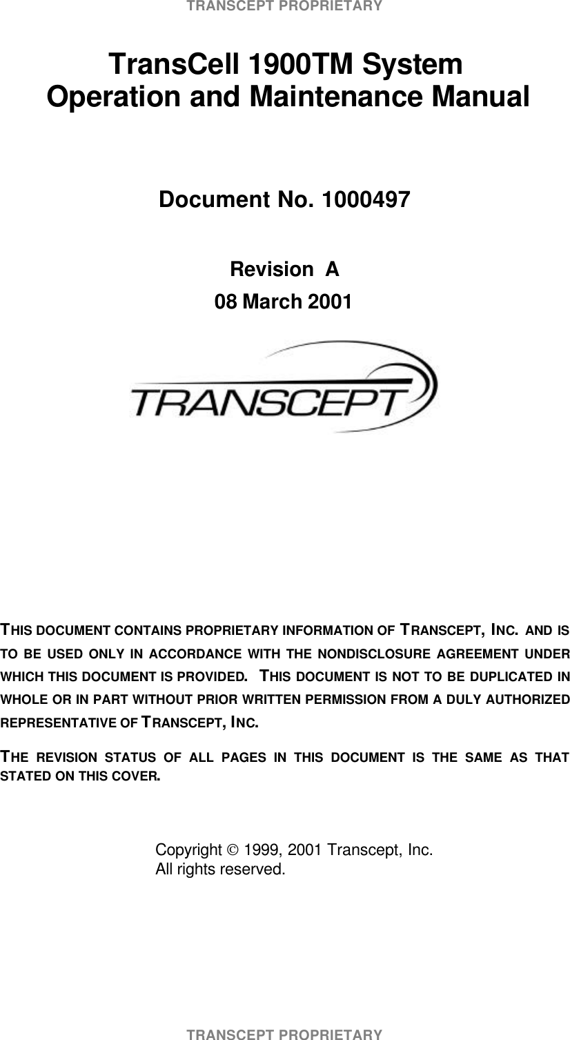
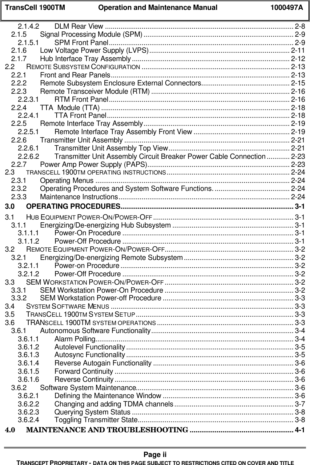
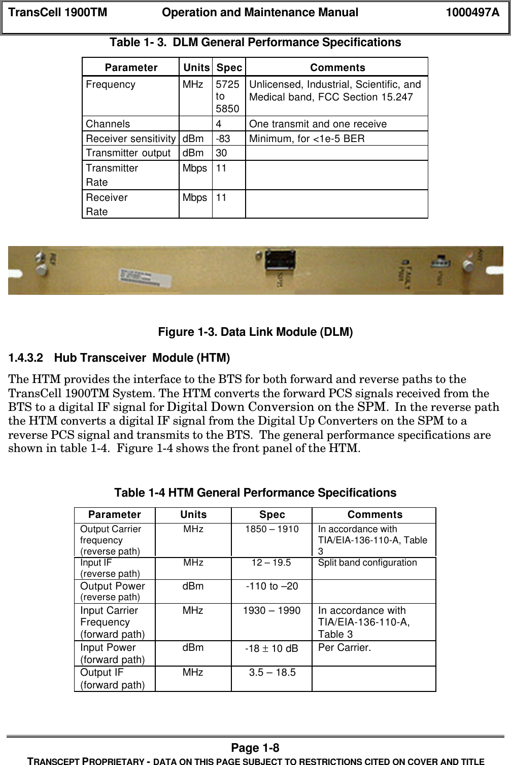
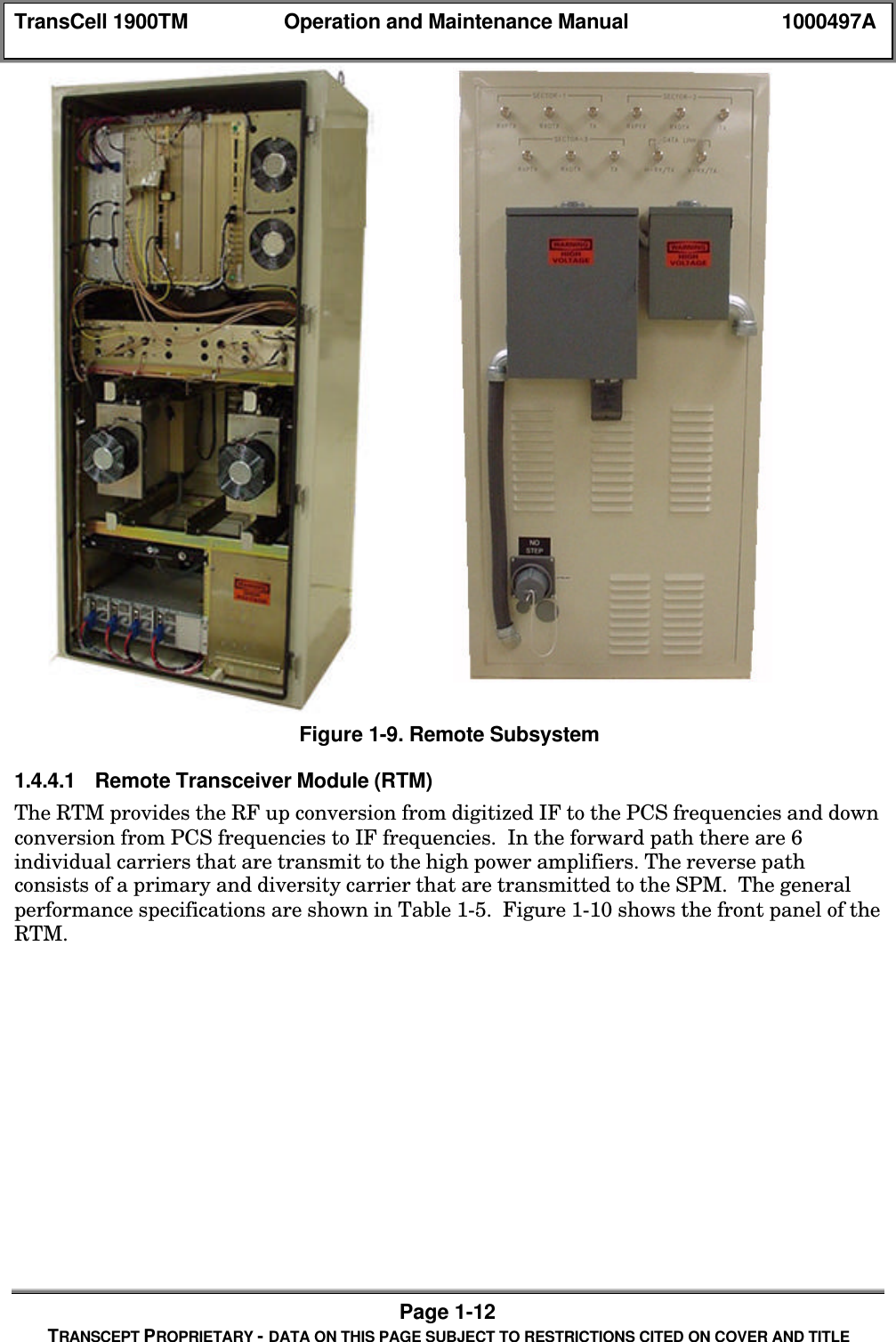
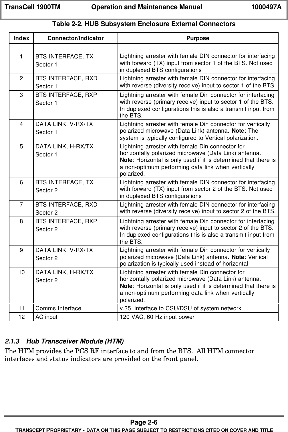
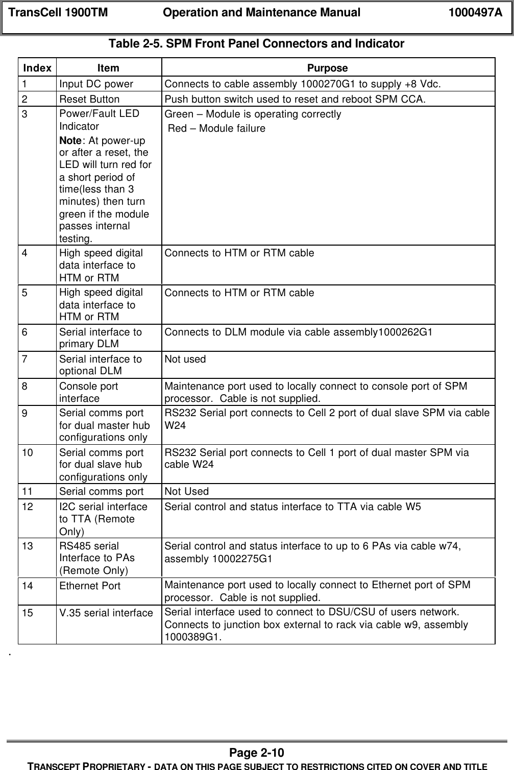
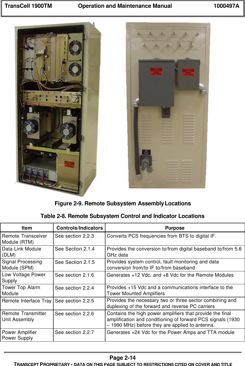
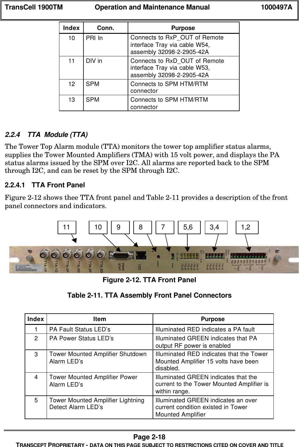
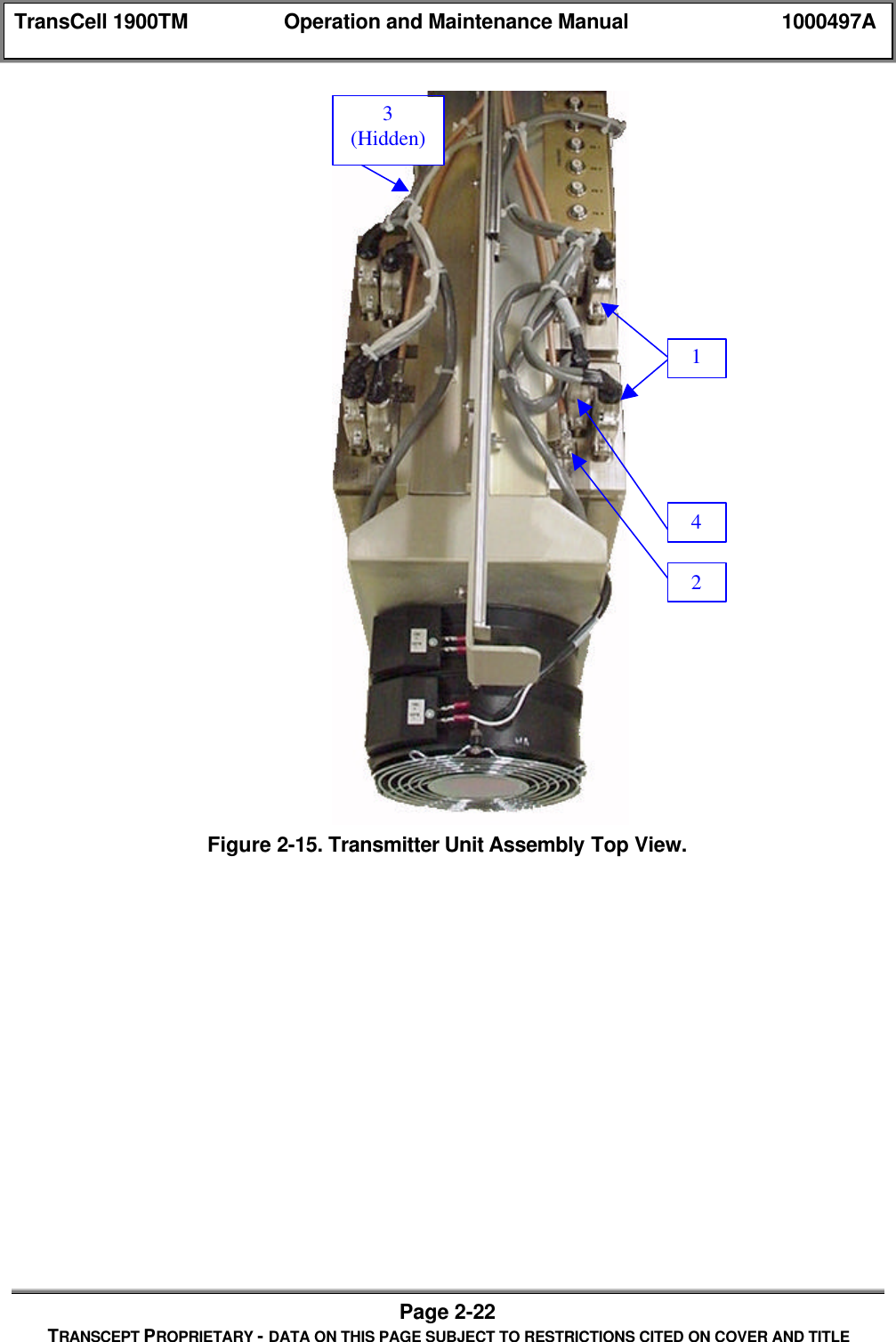
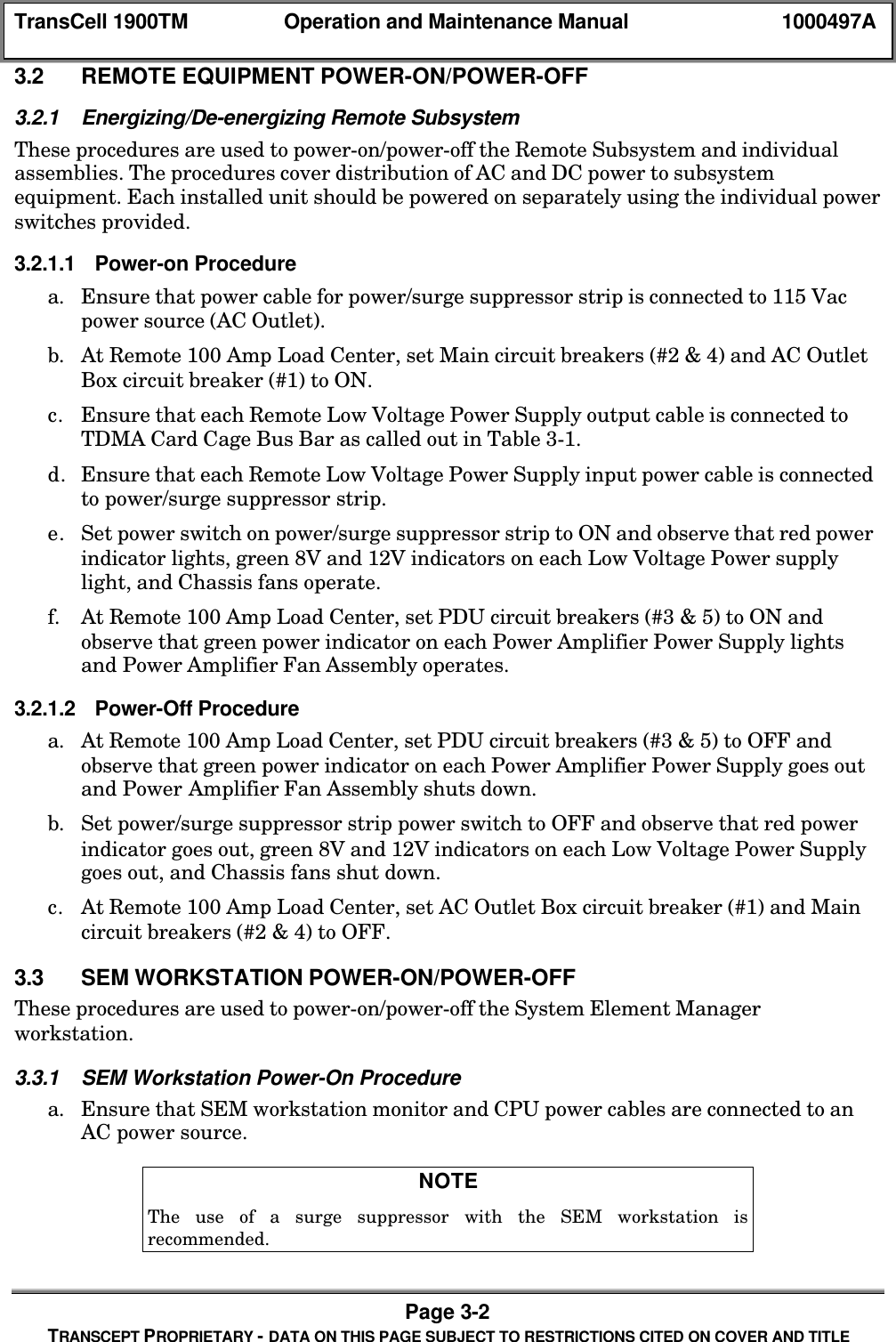

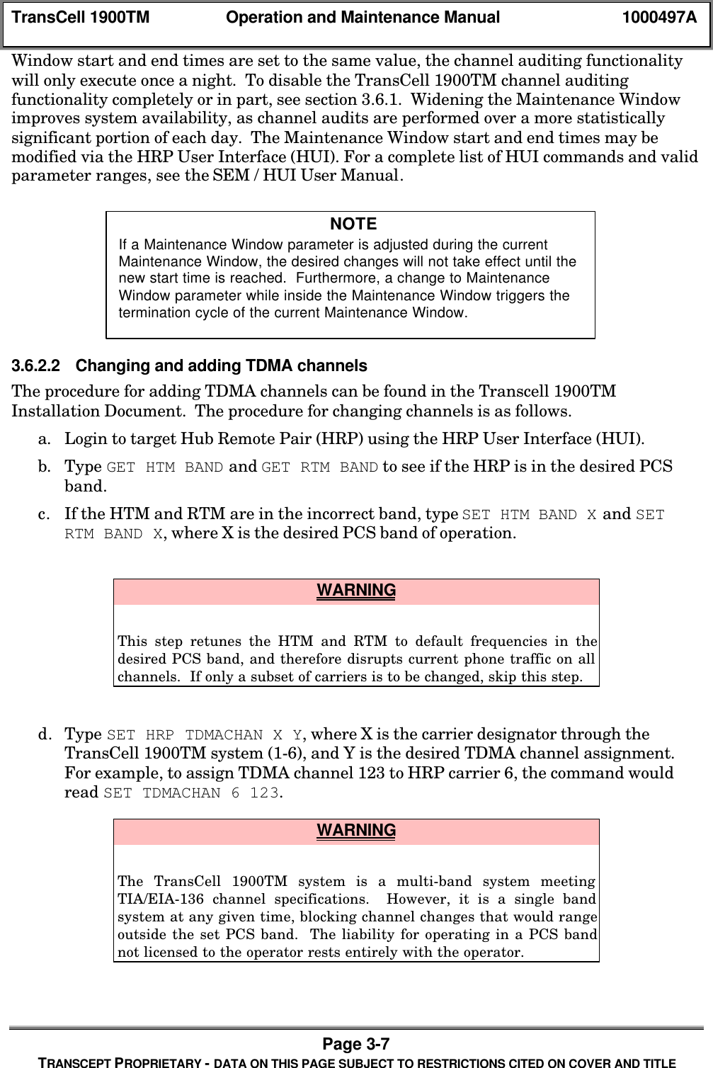
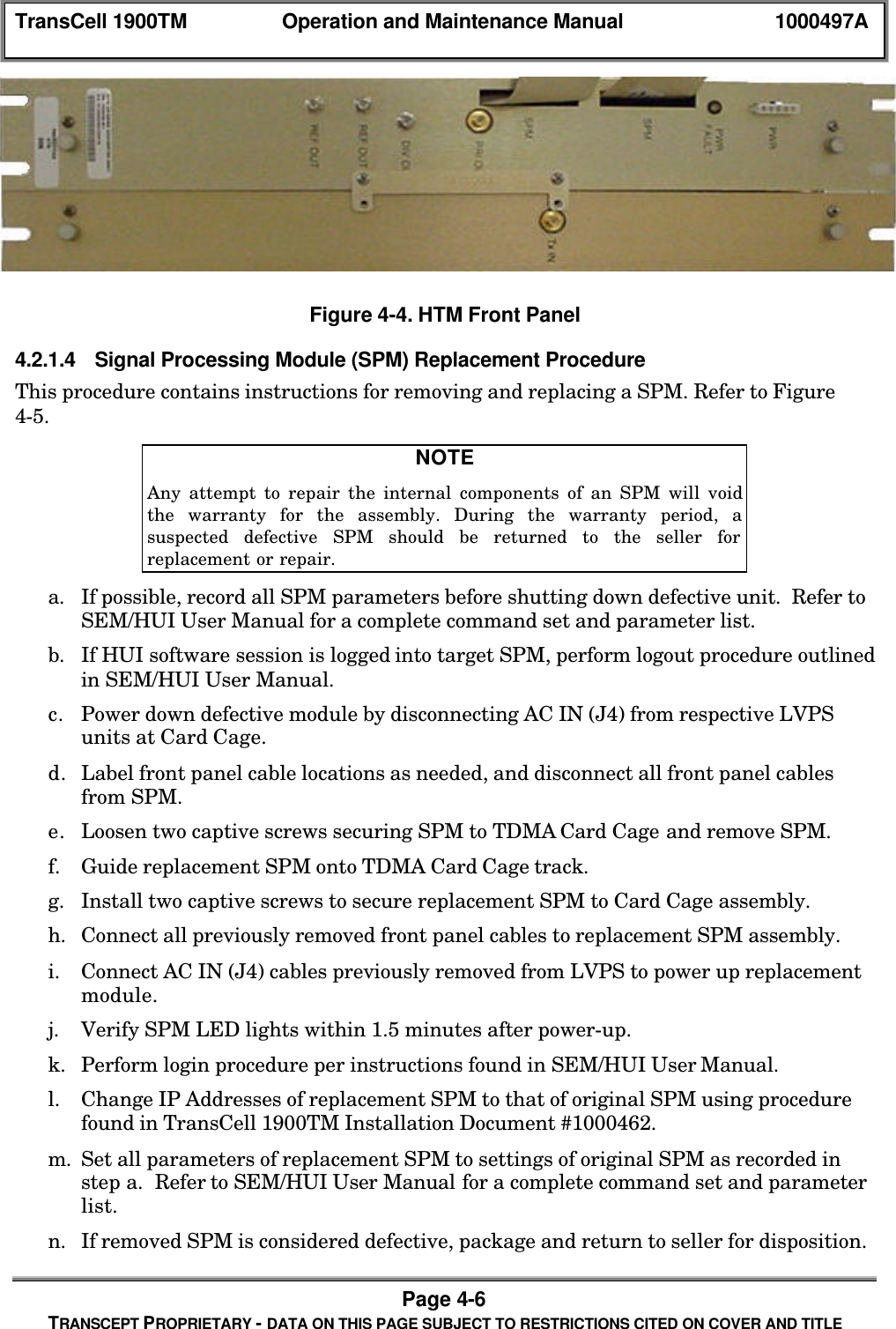
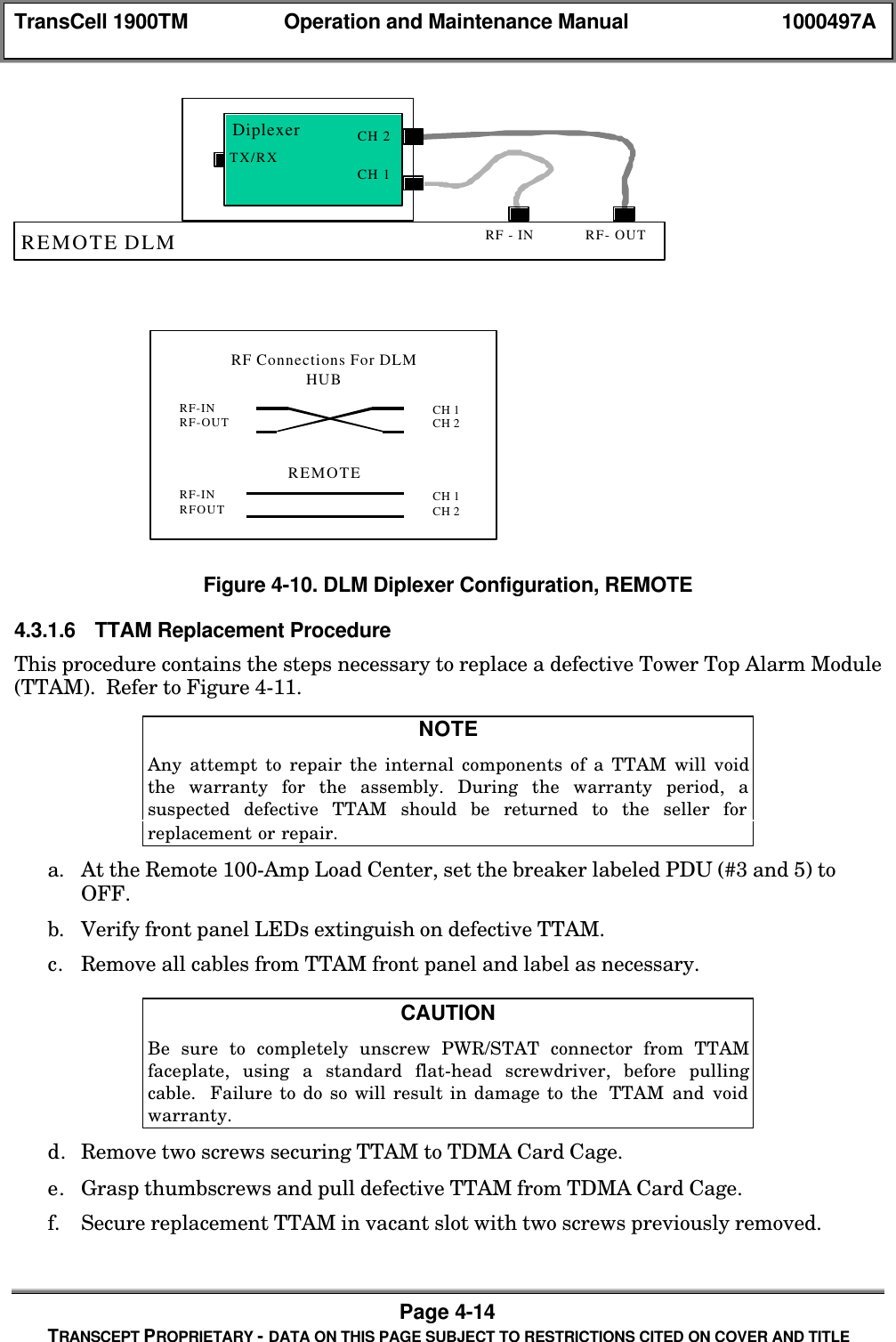
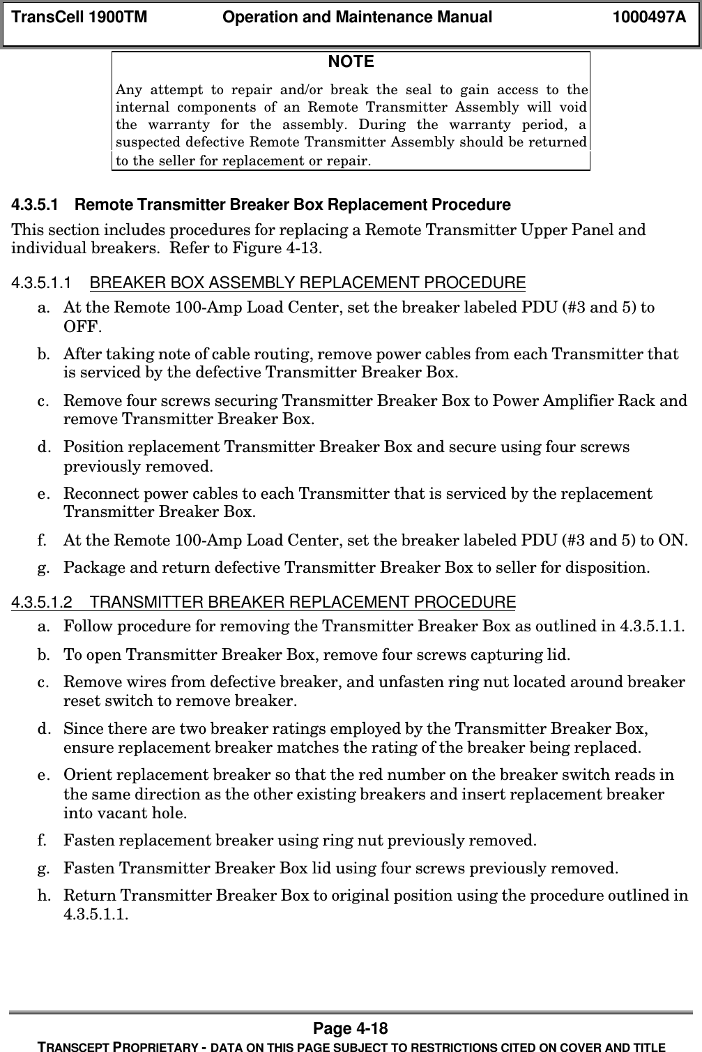
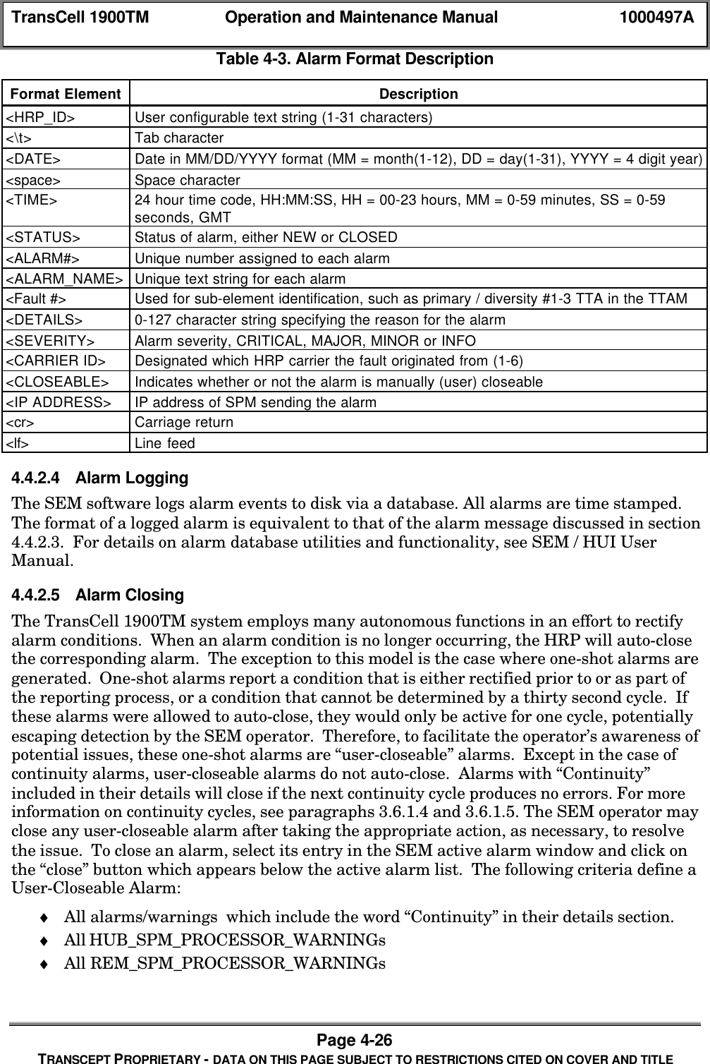
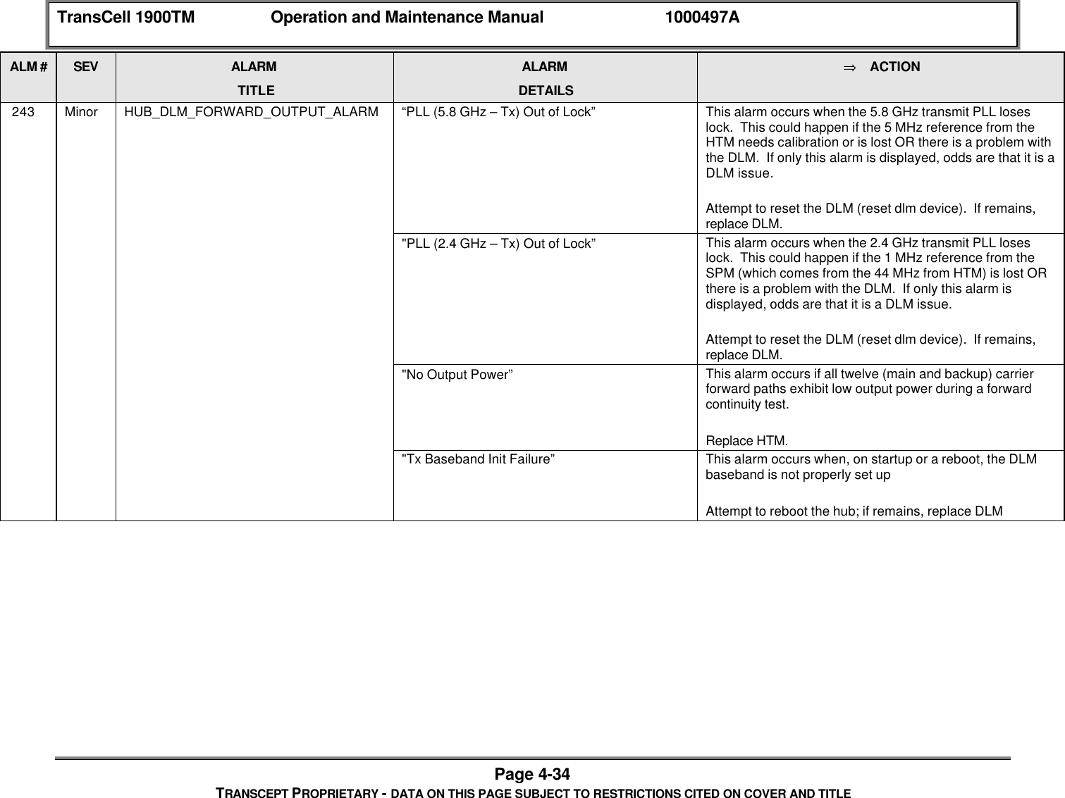
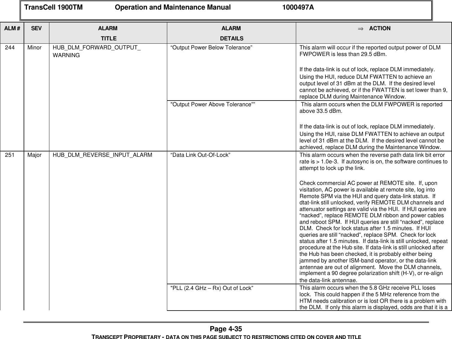
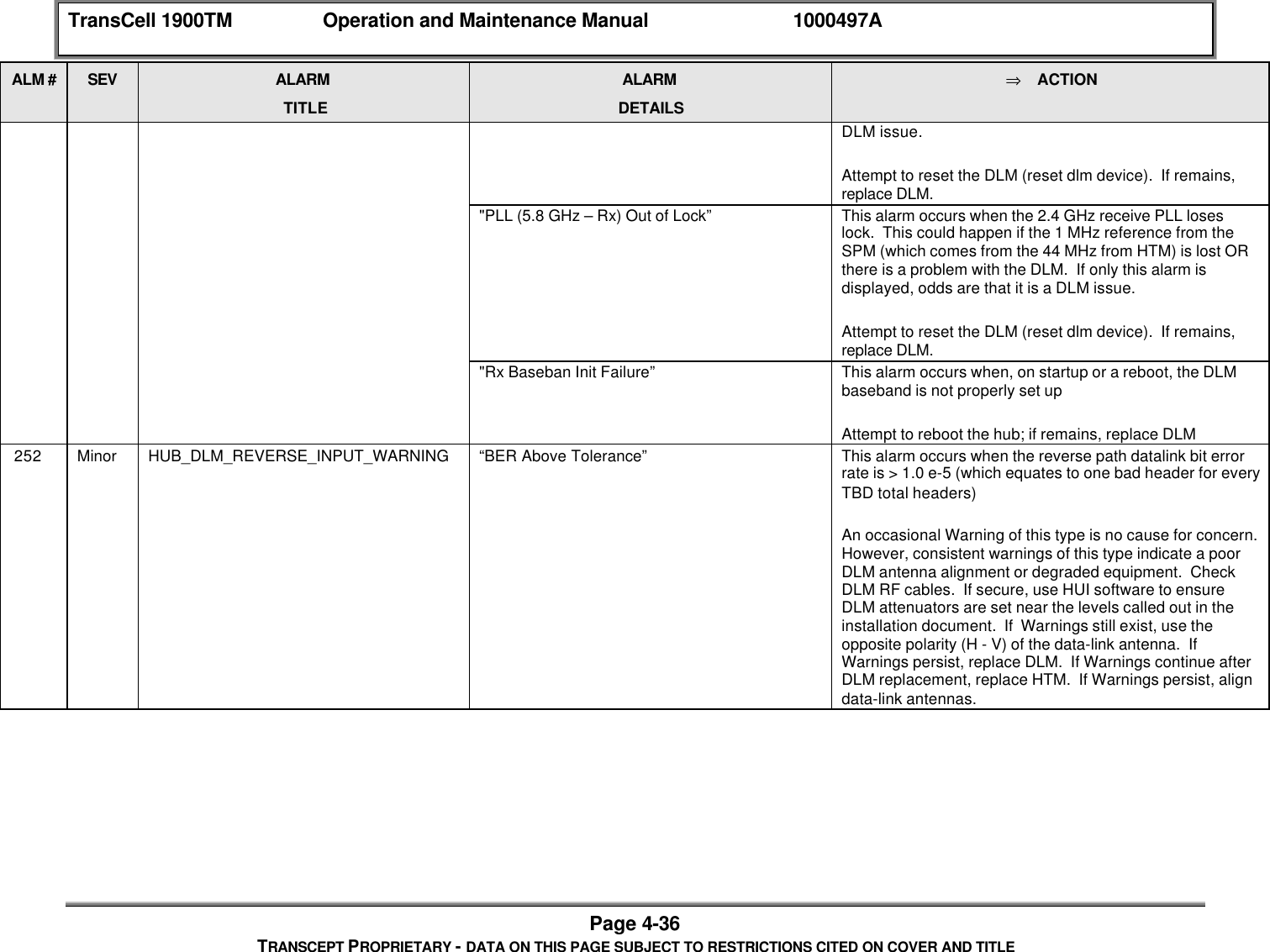
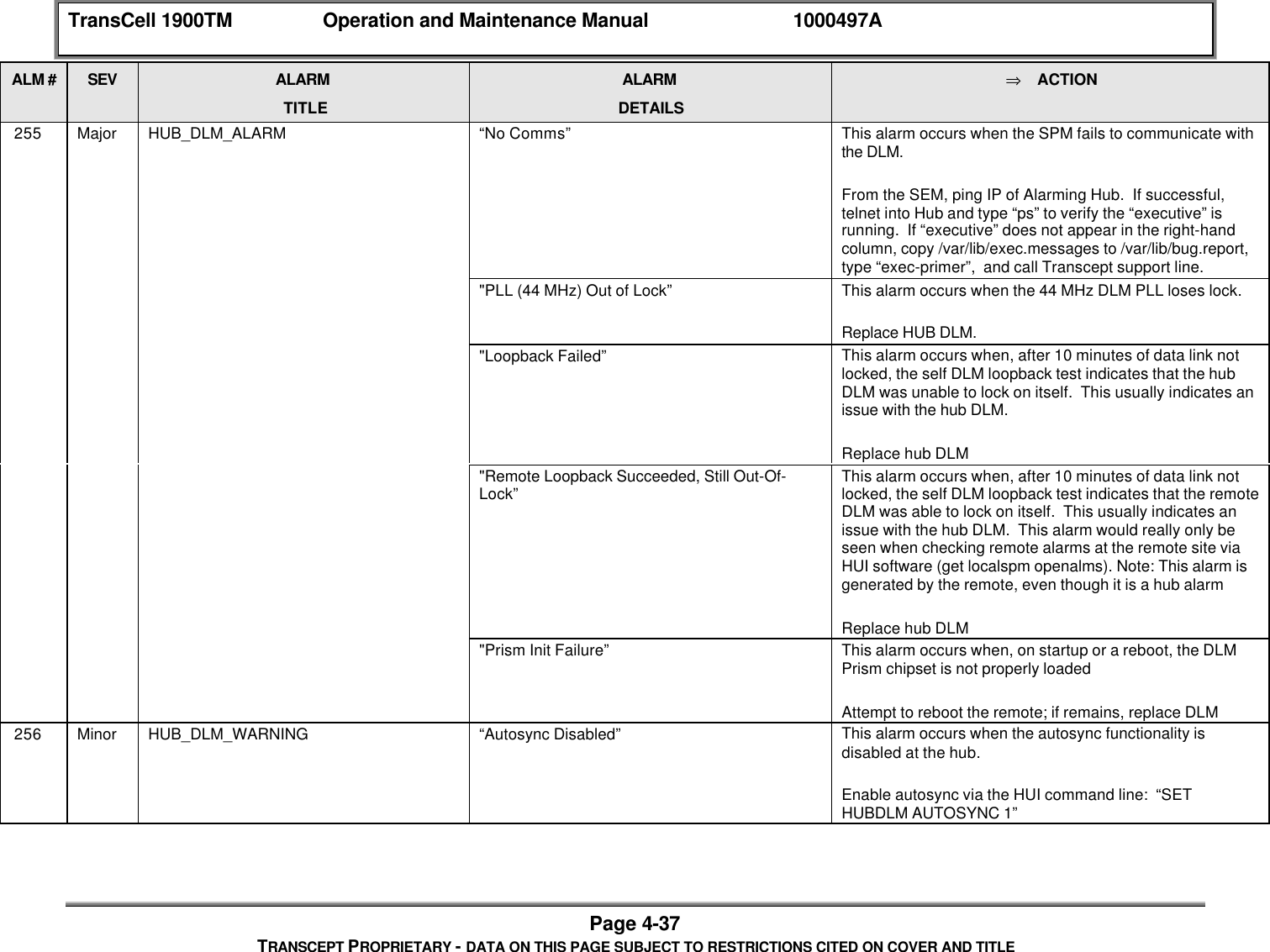
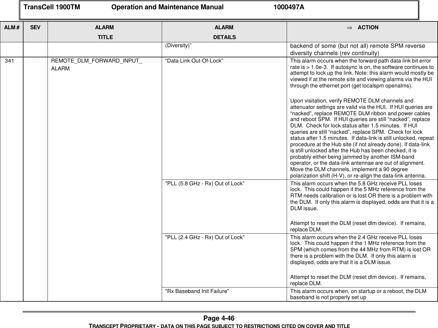
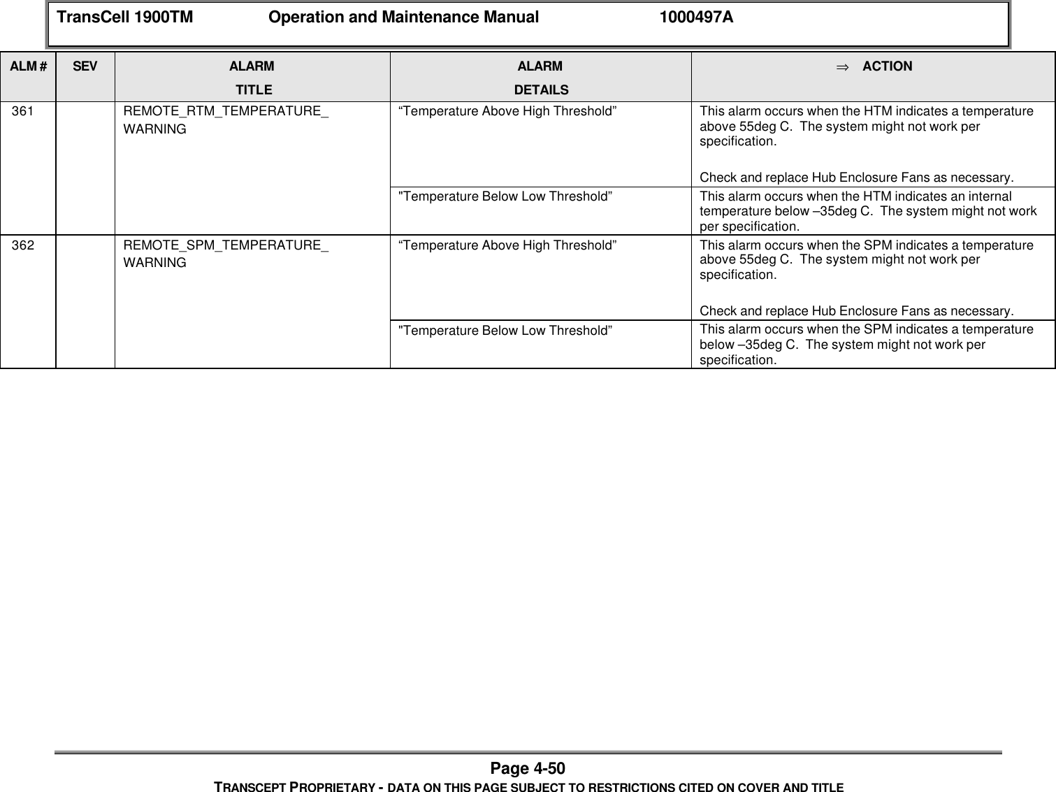
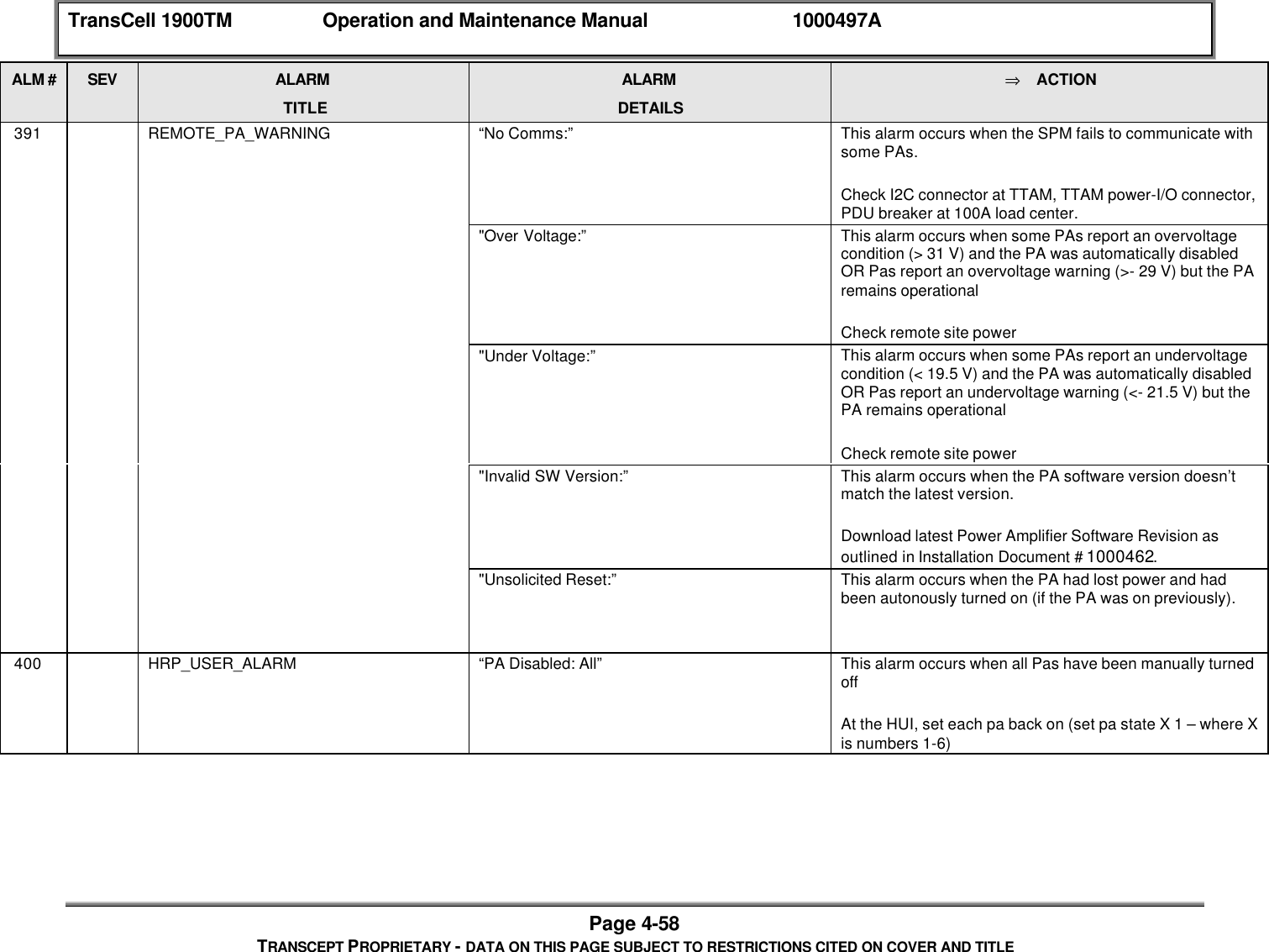
![TransCell 1900TM Operation and Maintenance Manual 1000497APage 4-23TRANSCEPT PROPRIETARY - DATA ON THIS PAGE SUBJECT TO RESTRICTIONS CITED ON COVER AND TITLE4.4.2.1 Software Fault DetectionThe SPMs in the Hub and Remote Subsystems perform fault detection on a scheduled basis.The software in the SPM monitors for new fault occurrences and absence of previousoccurrences. New faults are analyzed to determine if a new alarm should be generated. Thenon-repetition of previously detected faults results in the closing of one or more activealarms. Each TransCell 1900TM modulel has a hexidecimal fault bitmask which can bemodified to disable certain faults at a module level. However, this practice is notrecommended. See Table 4-2 for a complete bitmask list. If an alarm activity must bedisabled, it is recommended that it is disabled usint the alarm number via the HUI. Referto SEM/HUI User's Guide. The Hub and the Remote alarm statuses are reported to theSEM workstation through messages in SPM command language format.The Hub and Remote Subsystems are equipped with hardware watchdog timers. If thesoftware does not reset the watchdog timer during a preset time period, the watchdog timertimes out and issues a hardware reset to the Hub and Remote SPM processors.Table 4-2 Fault Bitmasks by ModuleModule BIT FaultLVPS [0] 8 Volt Fault for both Prim/Red[1] 12 Volt Fault for both Prim/Red[2] Lost AC Fault for both Prim/RedPAPS [0] Comms loss faultTTAM [0] 3 dB Loss[1] >=6 dB Loss[2] Power Disabled[3] DC Power[4] Battery backupSPM [0] Too Hot[1] Too Cold[2] No CommsPower Amp [0] Over Temperature Fault[1] Input Over Power Fault[2] Output Over Power Fault[3] Over Voltage Fault[4] Under Voltage Fault[5] Output VSWR Fault[6] Low Gain Fault[7] High Gain Fault[8] Warmup Period Fault[9] Reset Indication Fault[10] Spare 2[11] Spare 3](https://usermanual.wiki/OpenCell/TCELL1900TM.Exhibit-D-users-maunal-part-2/User-Guide-150763-Page-83.png)
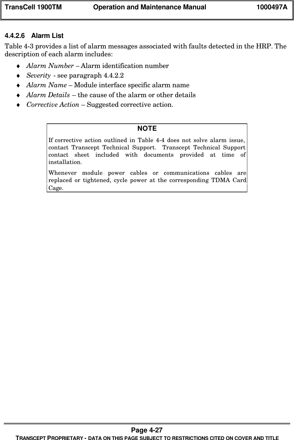
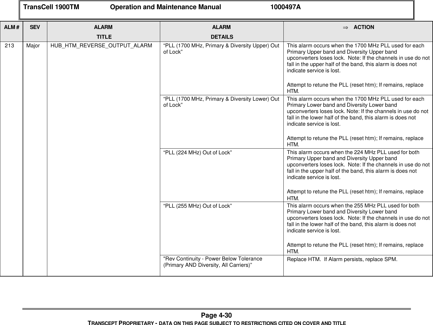
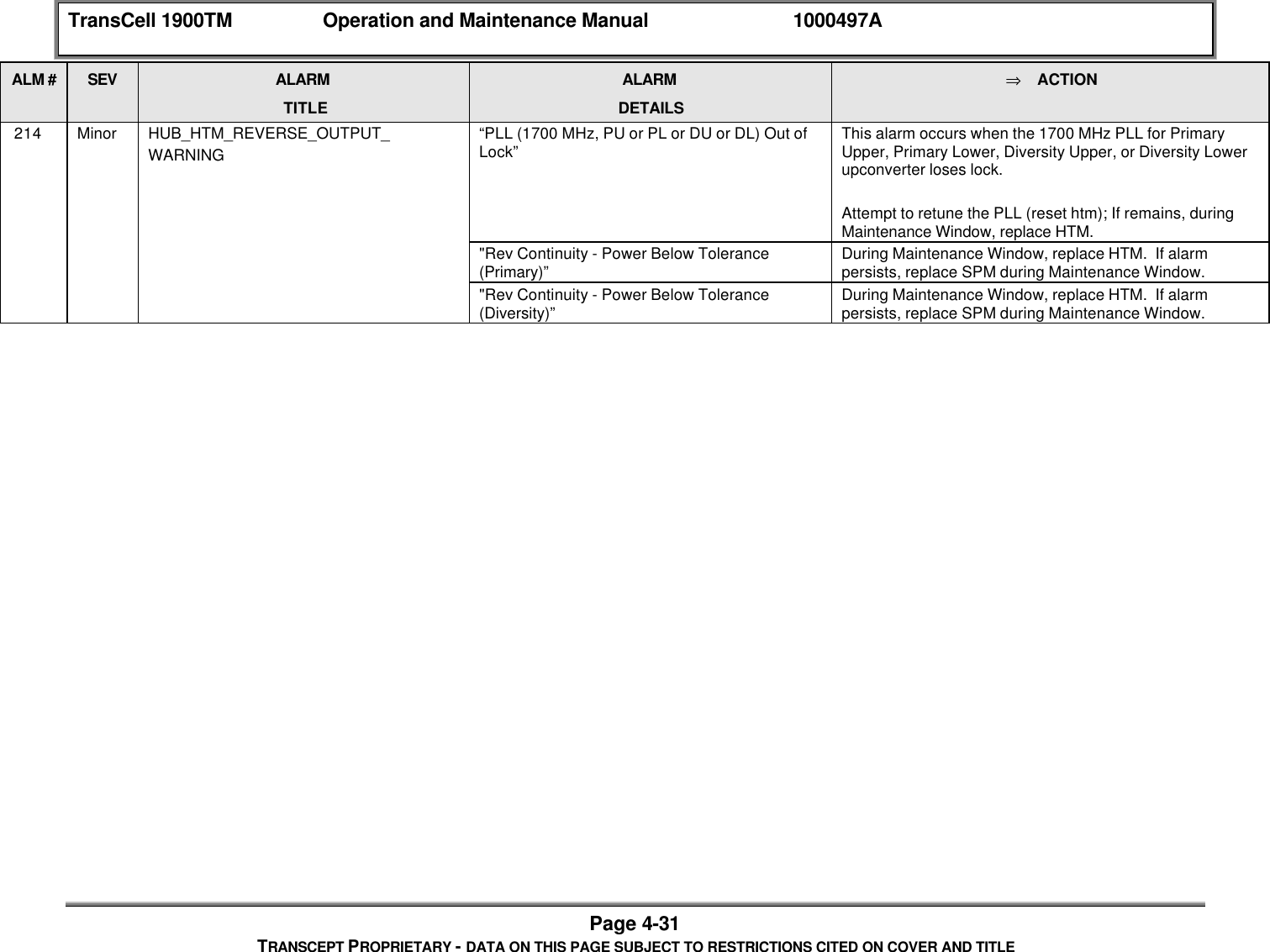
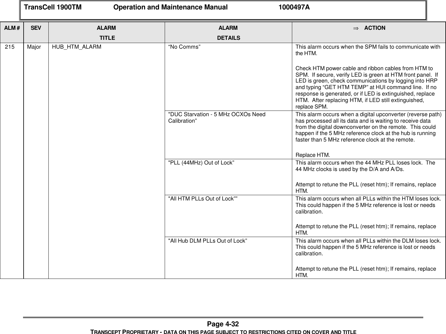
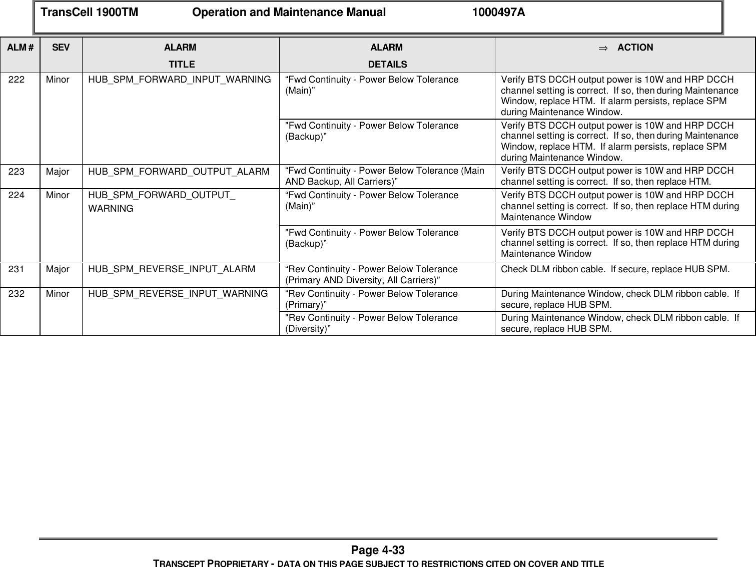
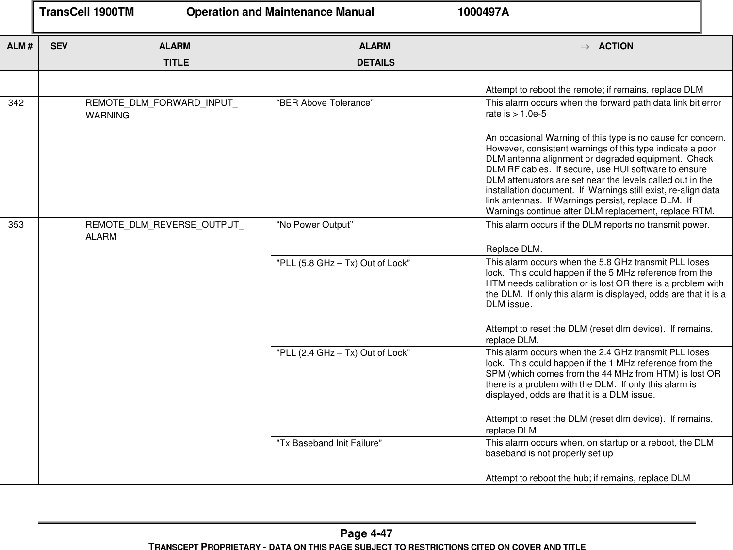
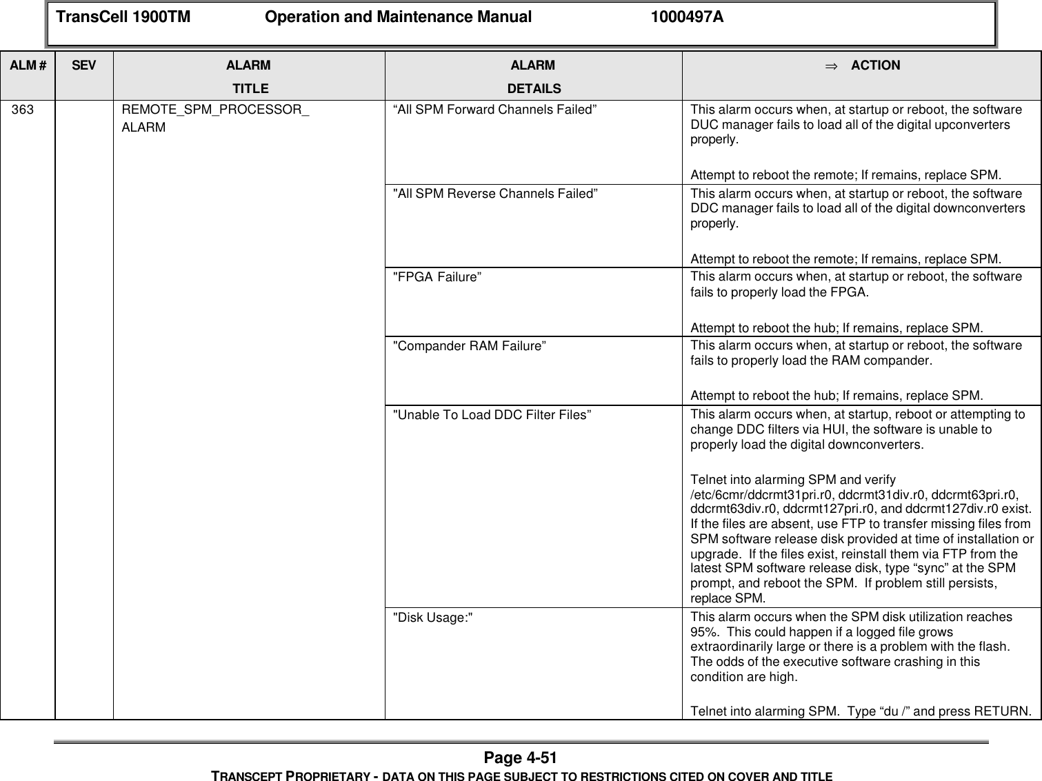
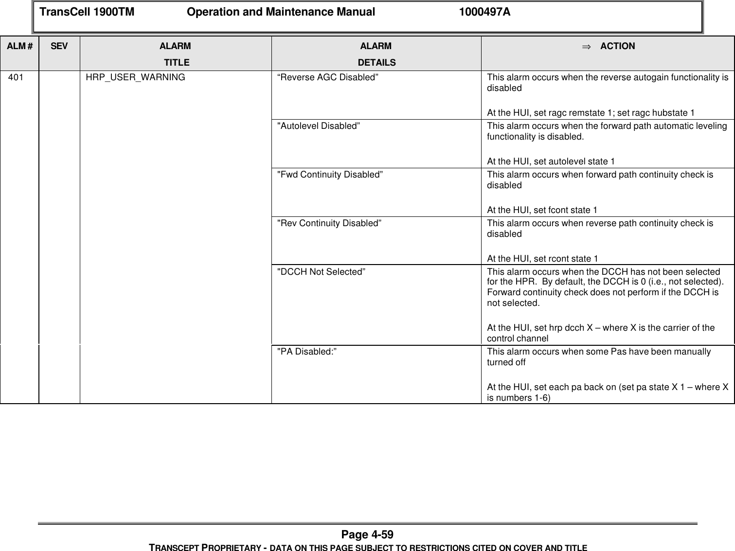
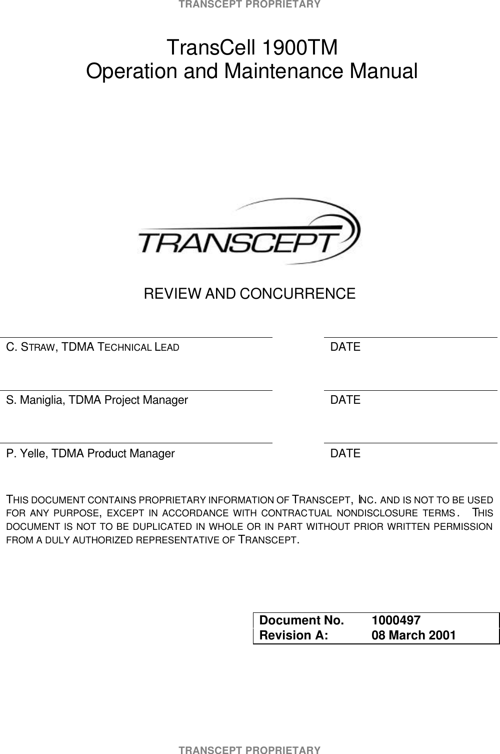
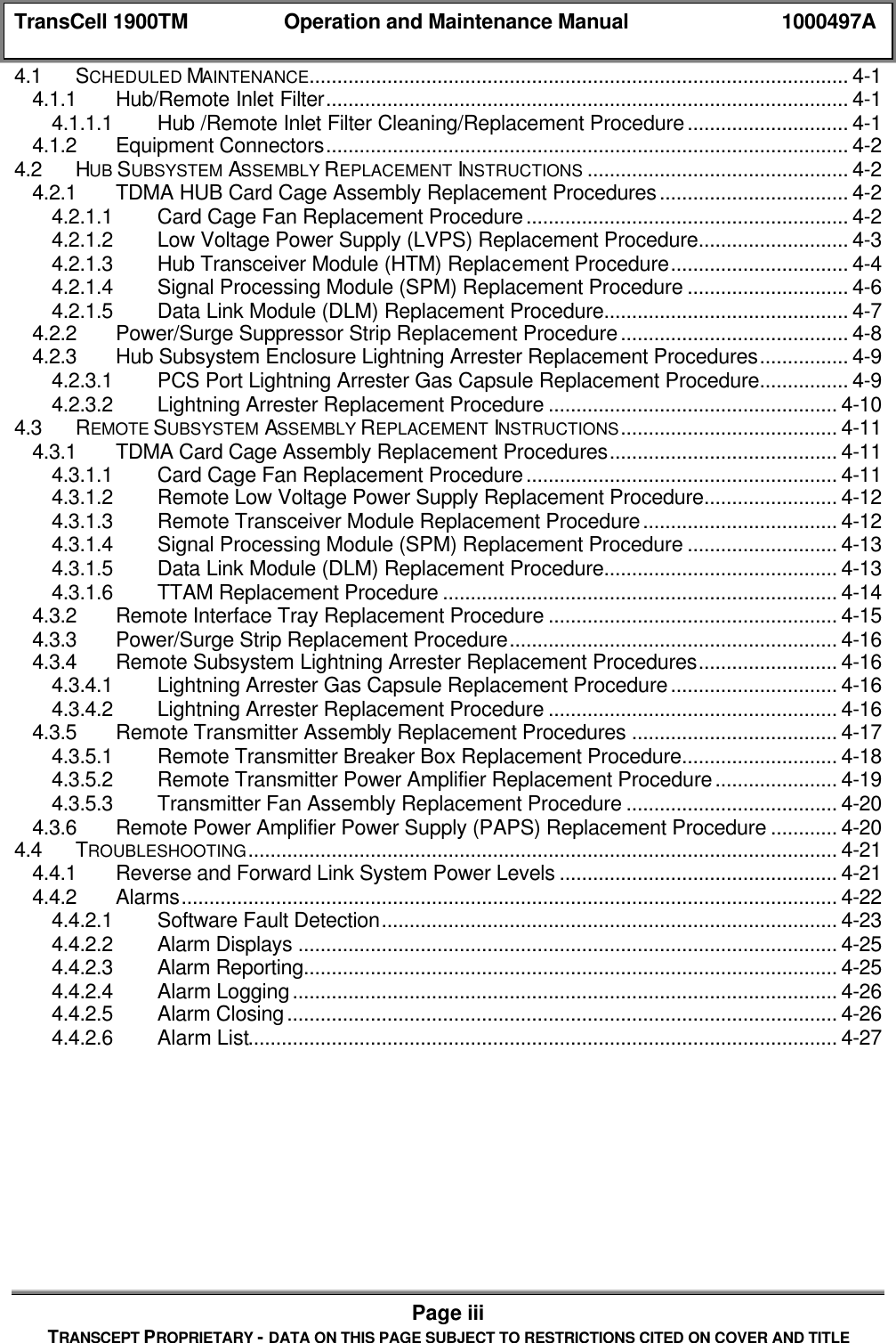
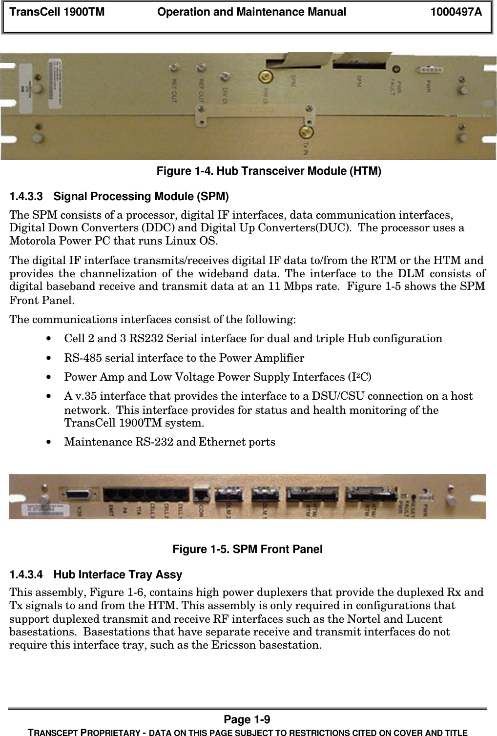
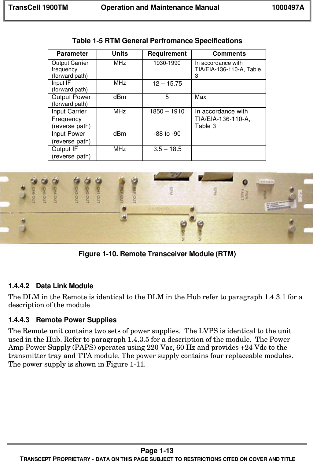
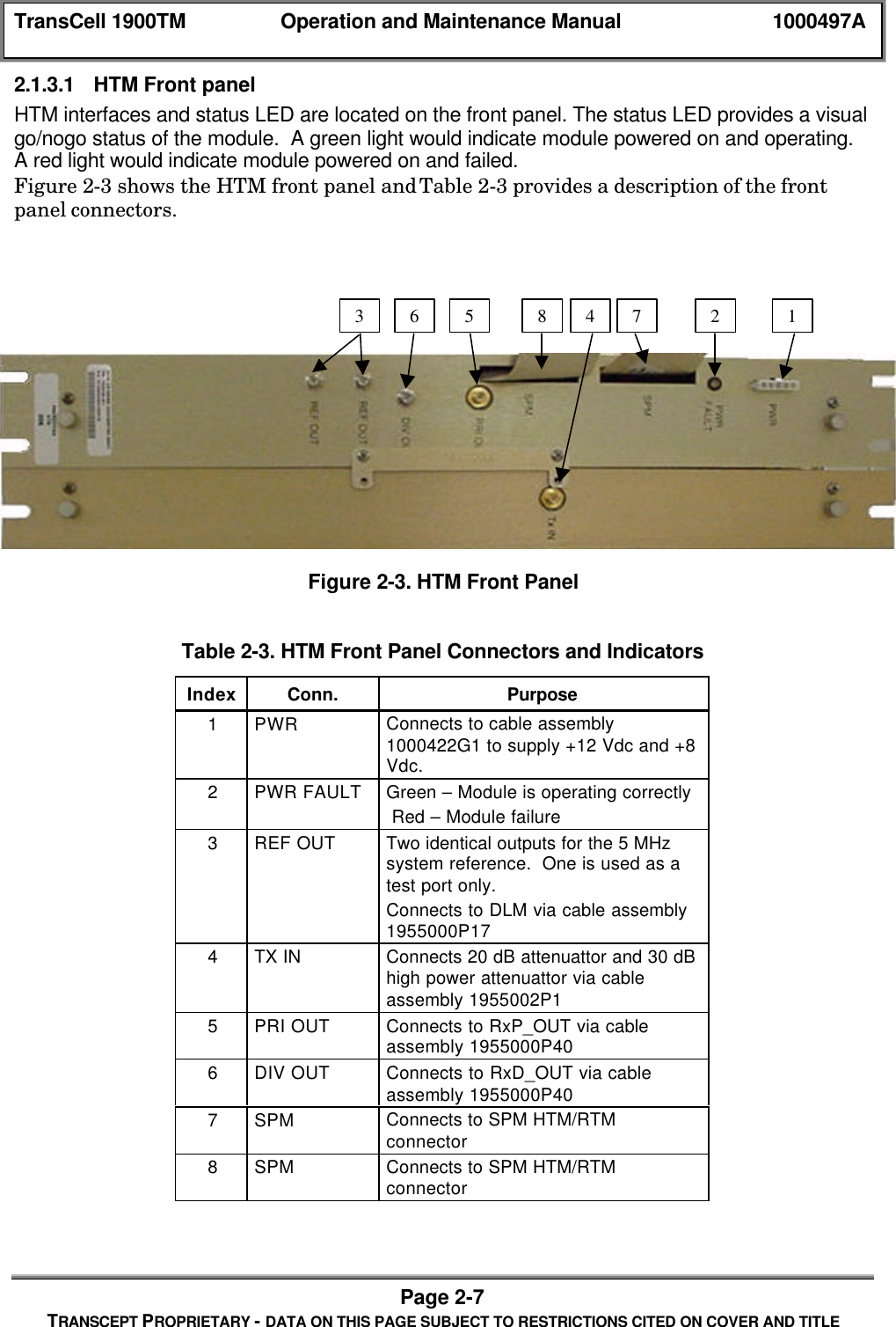
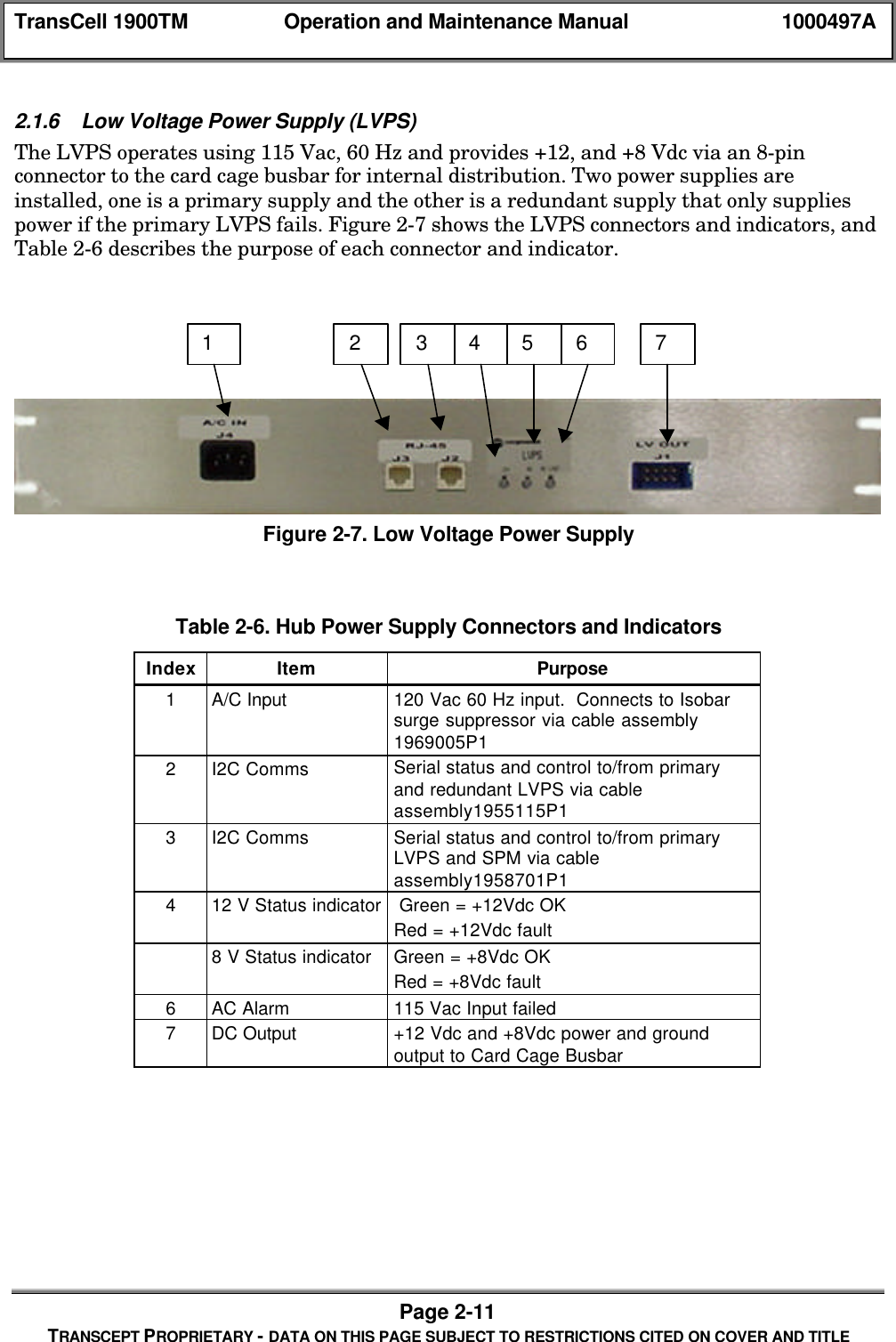
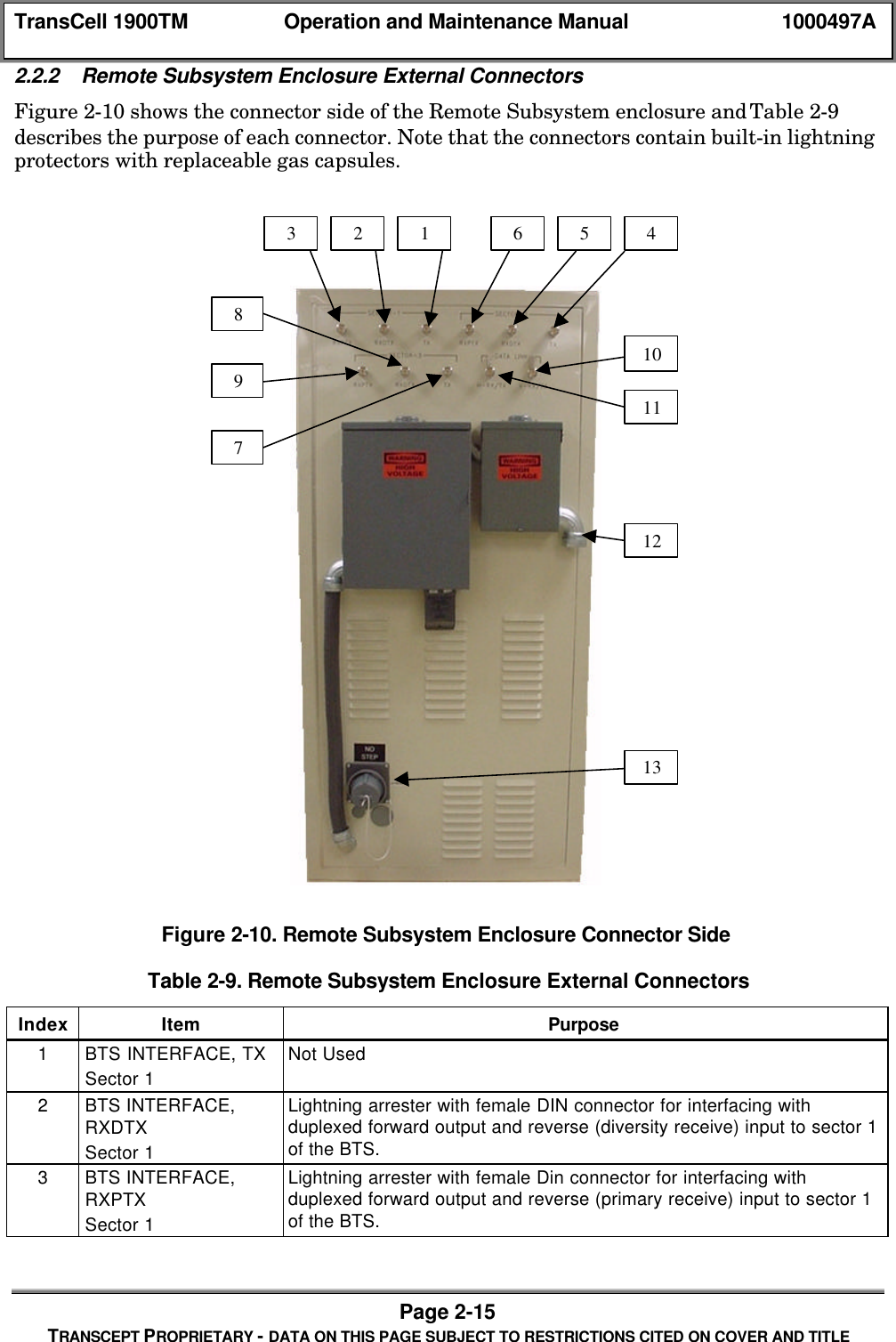
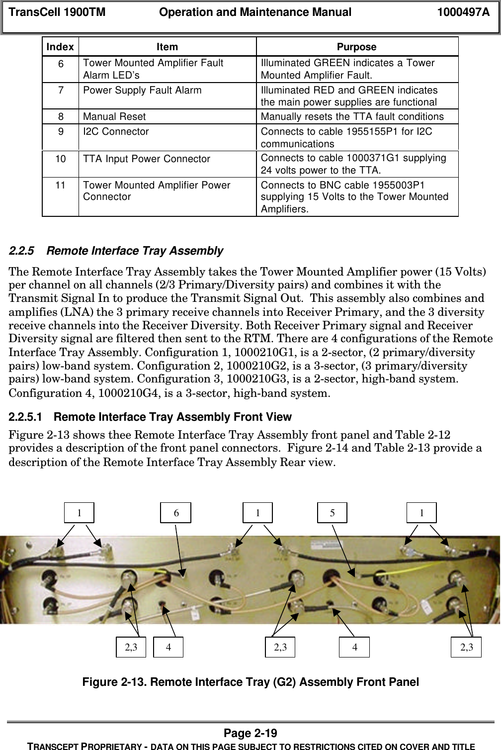
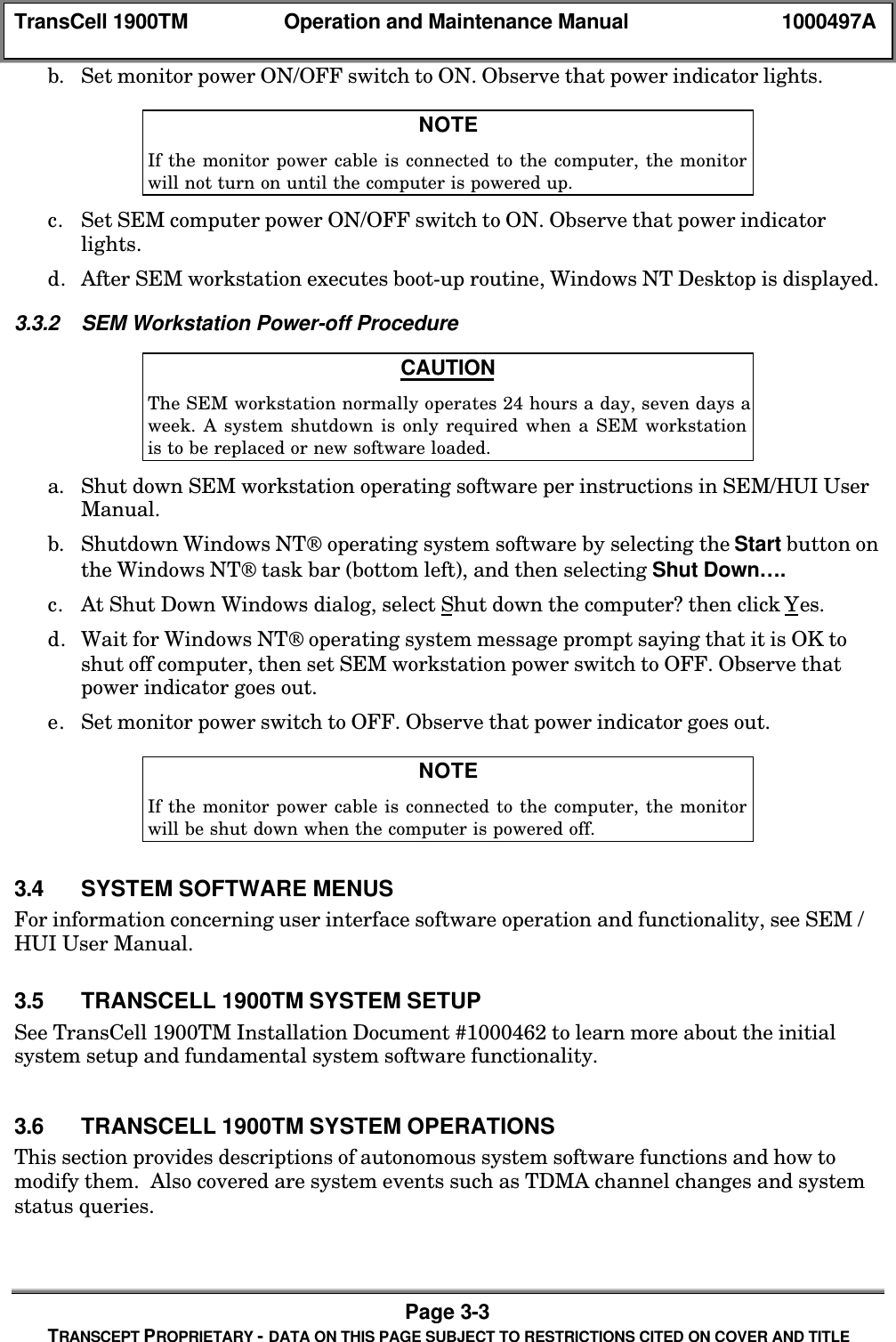
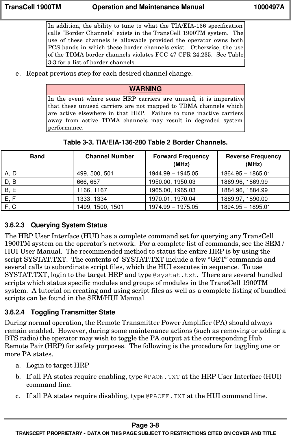
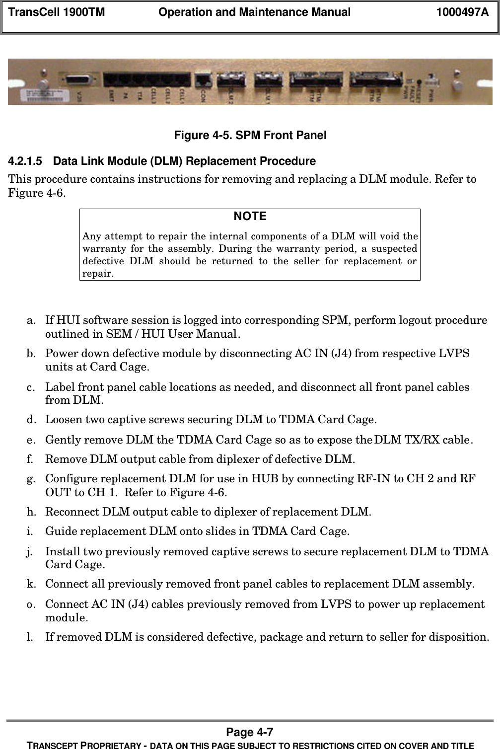
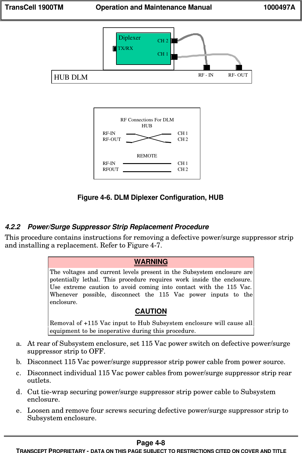
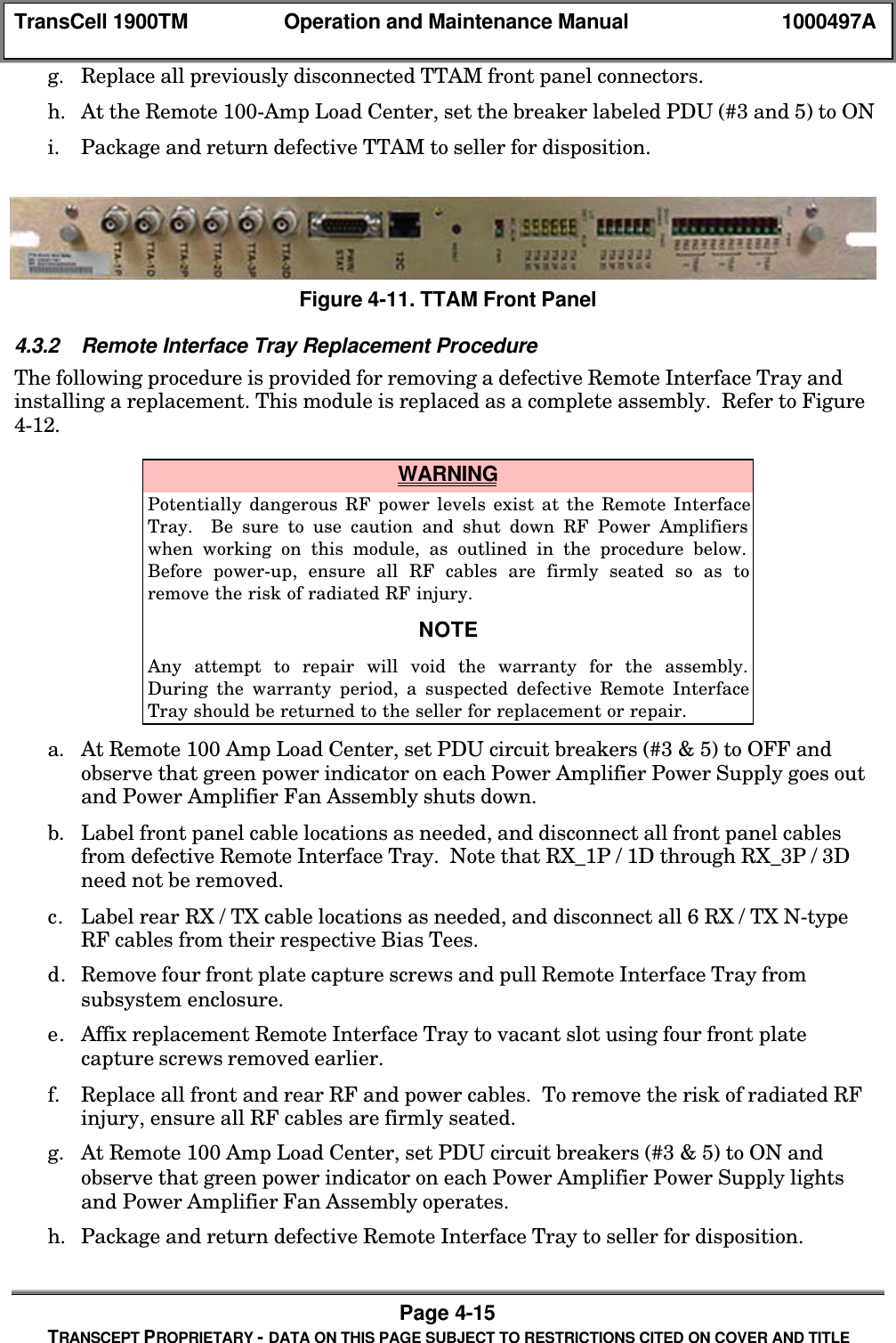
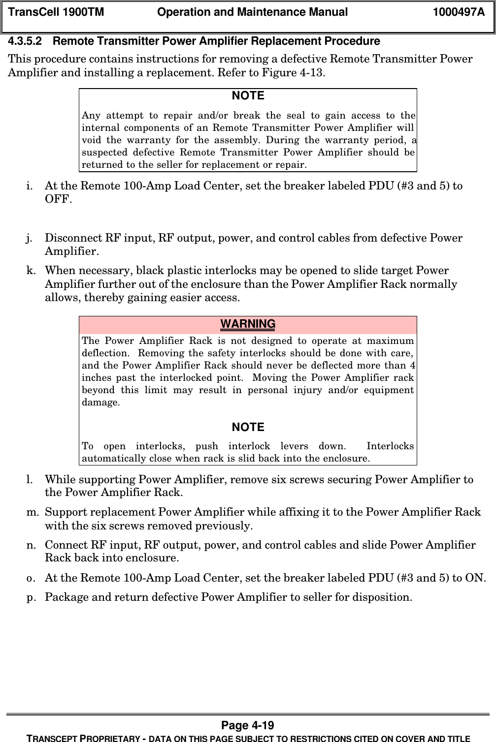
![TransCell 1900TM Operation and Maintenance Manual 1000497APage 4-24TRANSCEPT PROPRIETARY - DATA ON THIS PAGE SUBJECT TO RESTRICTIONS CITED ON COVER AND TITLE[12] Spare 4[13] Spare 5[14] Spare 6[15] Spare 7[16] AA Over Temperature Fault[17] AA Input Over Power Fault[18] AA Output Over Power Fault[19] AA Over Voltage Fault[20] AA Under Voltage Fault[21] AA Output Reduction 1[22] AA Output Reduction 2[23] AA Output Reduction 3[24] Version Check Fault[25] Disabled Fault[26] CONT DCCH Input Fault[27] CONT DCCH Output FaultDLM [0] Out of Lock Fault[1] High BER Fault[2] No I2C Comms Fault[3] PLL 24 TX Unlock Fault[4] PLL 24 RX Unlock Fault[5] PLL 58 TX Unlock Fault[6] PLL 58 RX Unlock Fault[7] PLL 44 Unlock Fault[8] Prism Init Fault[9] Baseband TX Init Fault[10] Baseband RX Init Fault[11] Loopback Good Fault[12] Loopback Bad Fault[13] Low Output Power Fault[14] High Output Power Fault[15] Output Power Out Fault[16] Autosync Disabled FaultHTM [0] No I2C Comms Fault[1] 203_0 Fault 17000 PLLs (Main AND Backup)[2] 203_1 Fault 173 PLL[3] 204 Fault 1700 PLL (Main OR Backup)[4] 213_0 Fault 1700 PLL (Prim AND Div Upper)[5] 213_1 Fault 1700 PLL (Prime AND Div Lower)[6] 213_2 Fault 224 PLL[7] 213_3 Fault 255 PLL[8] 214_0 Fault 1700 PLL (Prime OR Div Upper)[9] 214_3 Fault 1700 PLL (Prime OR Div Lower)[10] 215_0 Fault 44 PLL[11] 215_1 Fault ALL HTM PLLs[12] 261_HI Fault High Temp[13] 261_LO Fault Low Temp](https://usermanual.wiki/OpenCell/TCELL1900TM.Exhibit-D-users-maunal-part-2/User-Guide-150763-Page-84.png)
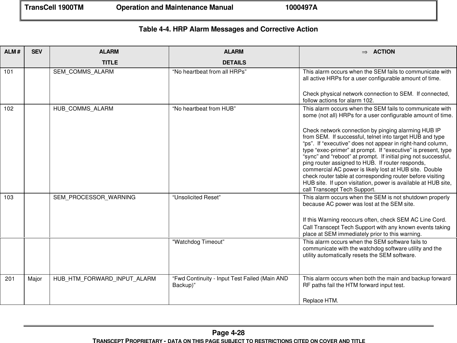
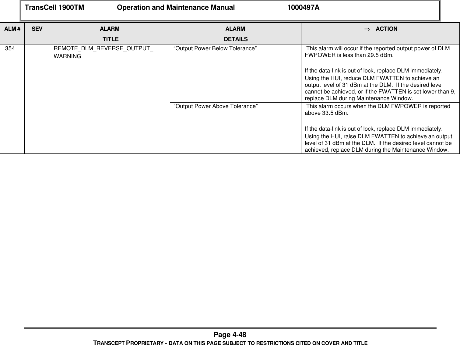
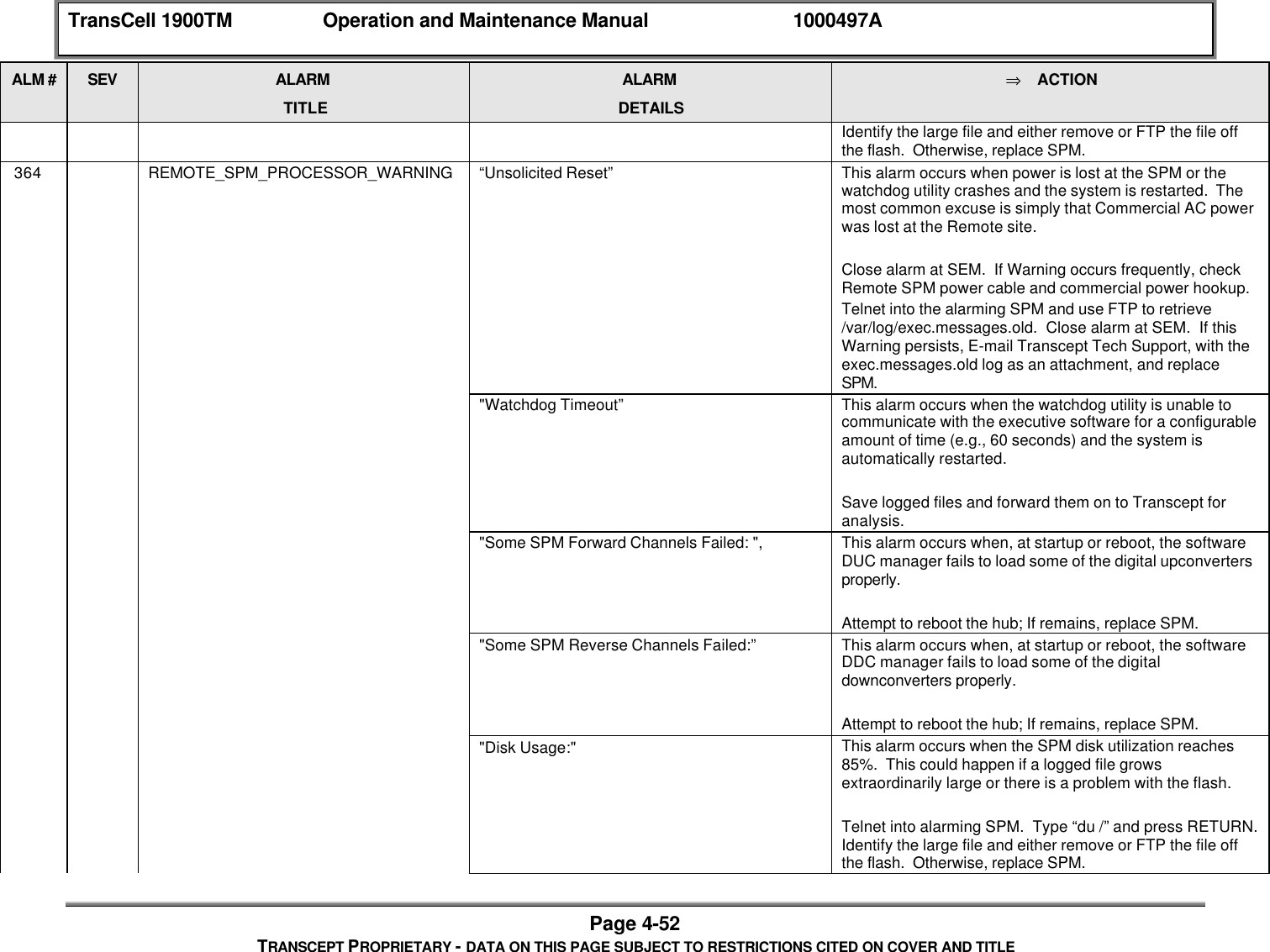
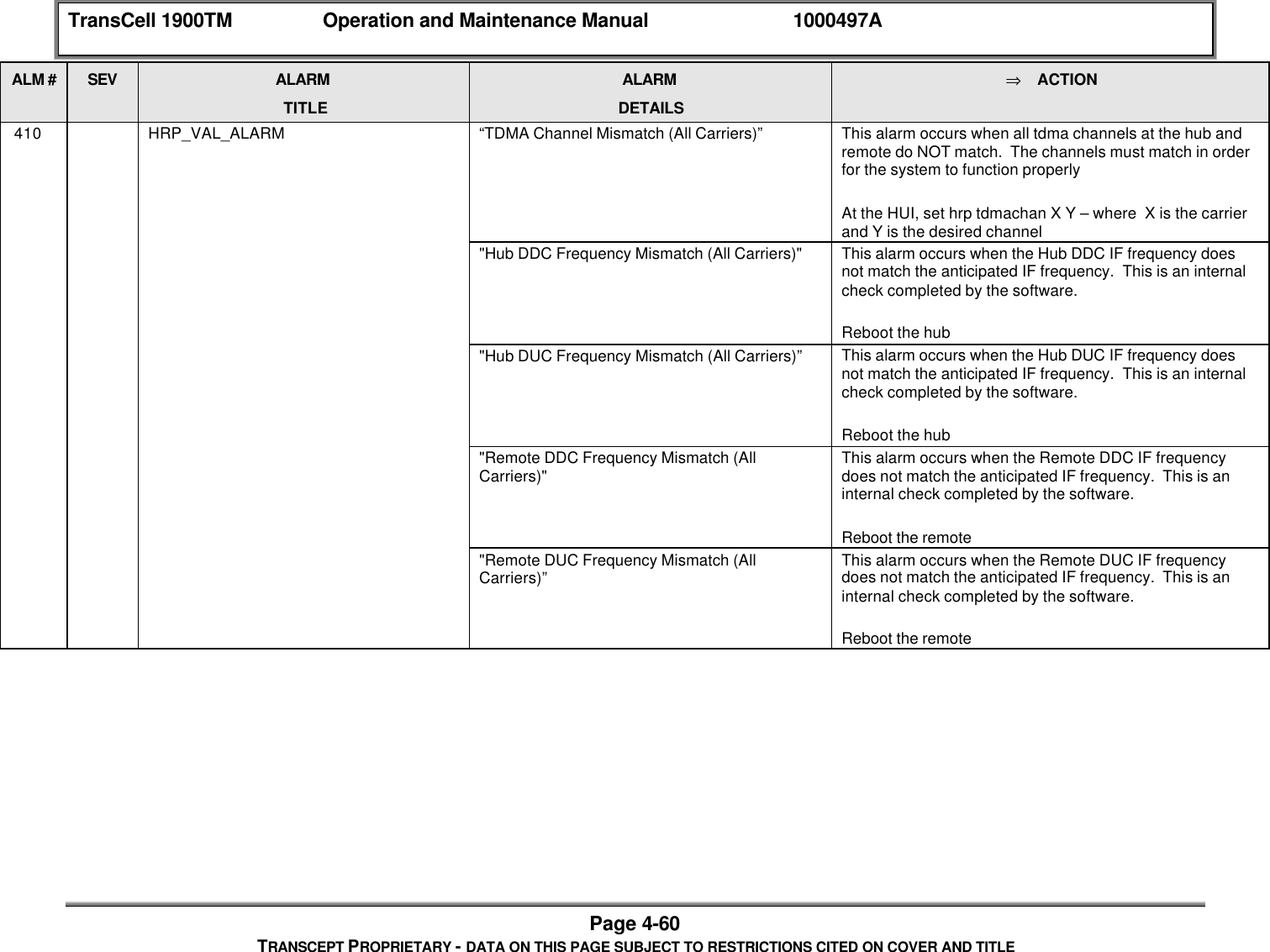
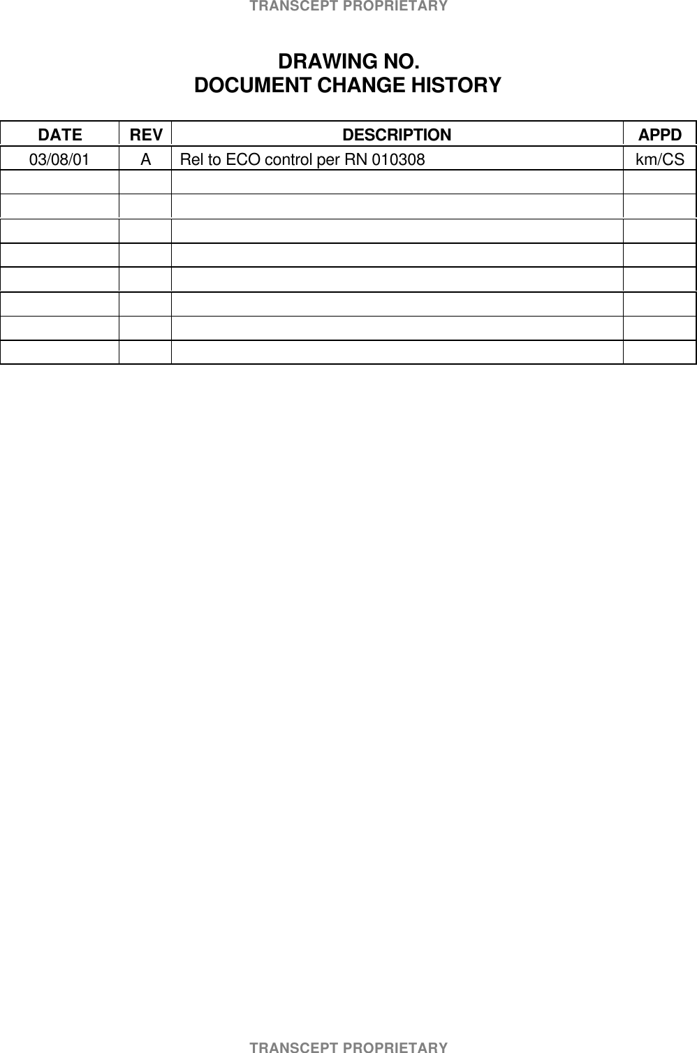
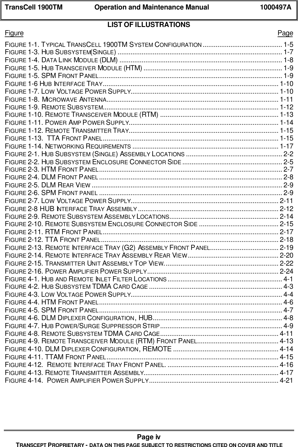
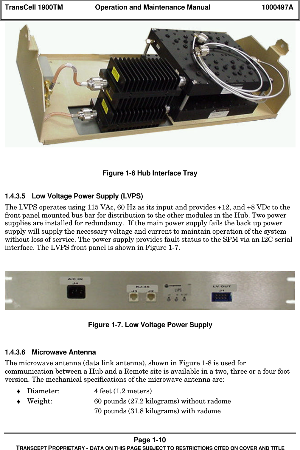
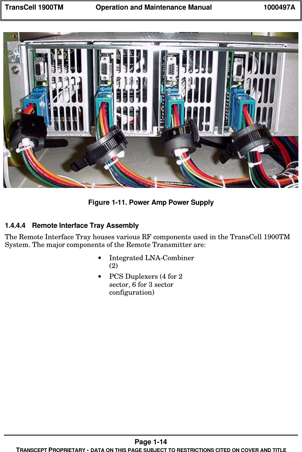
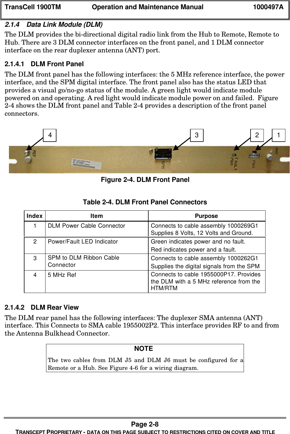
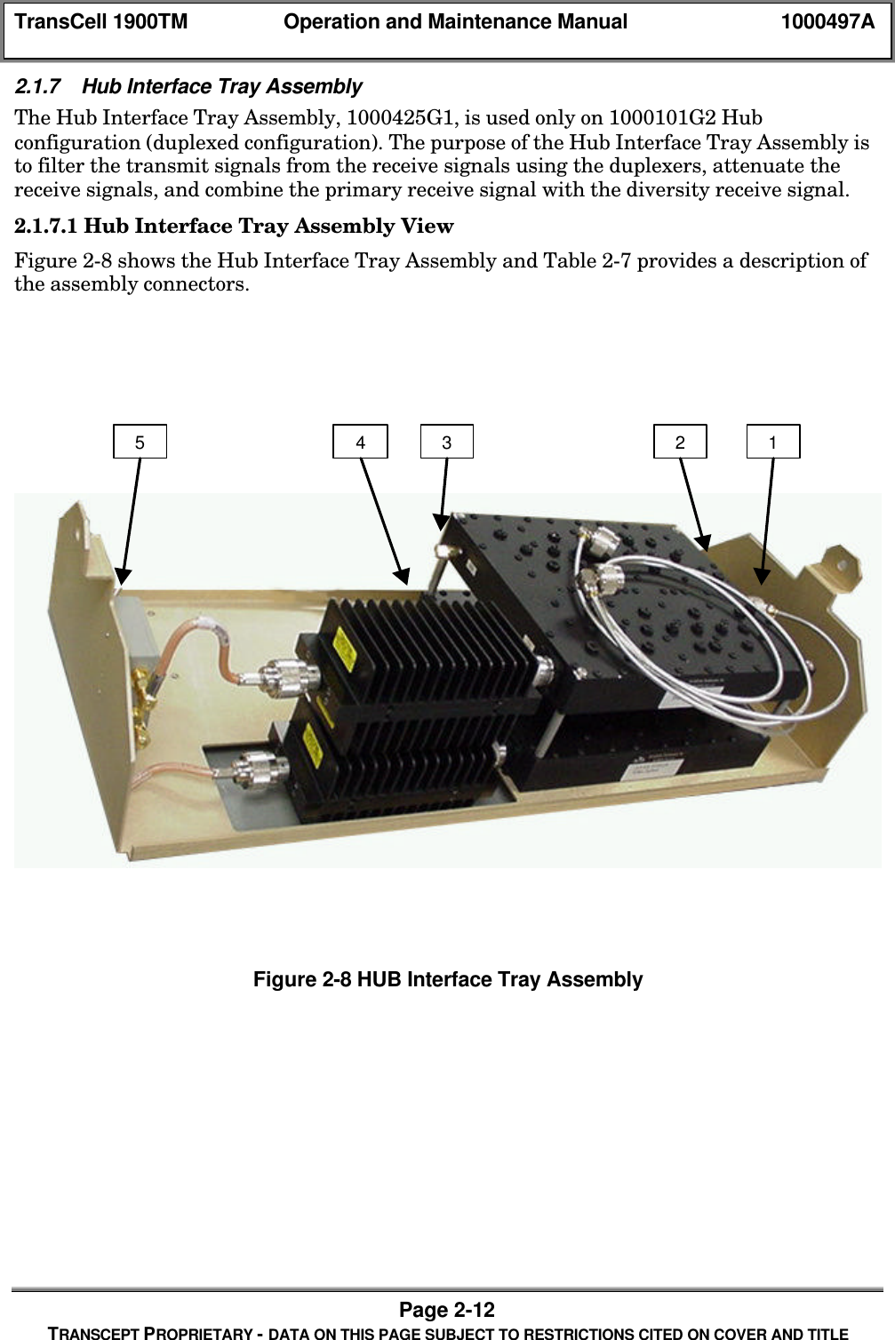
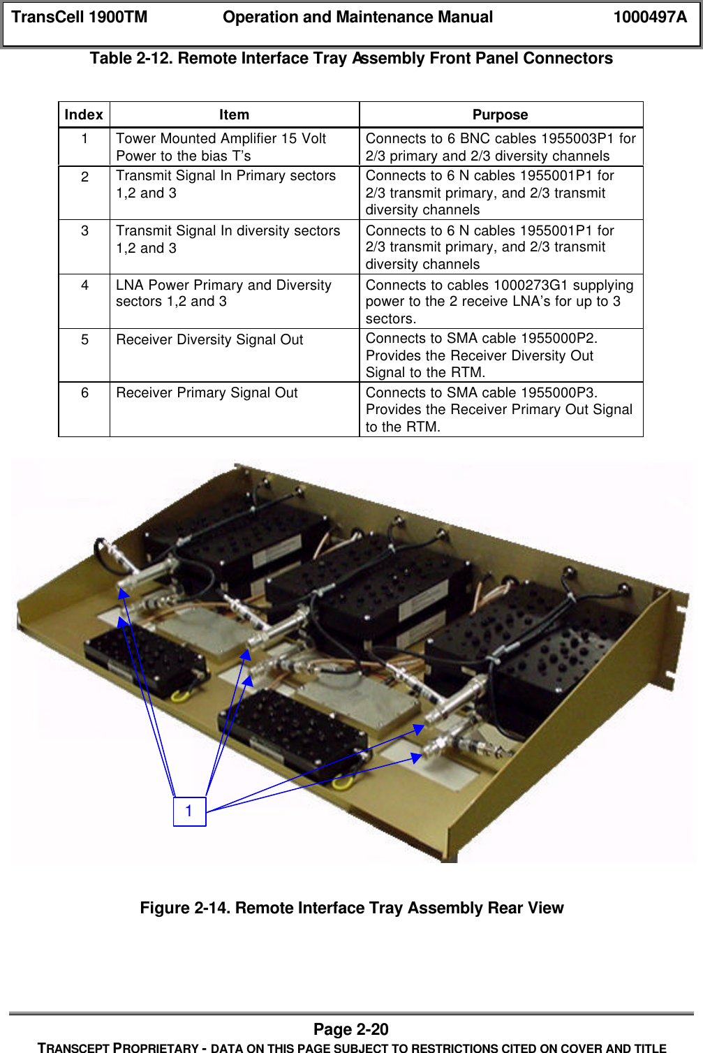
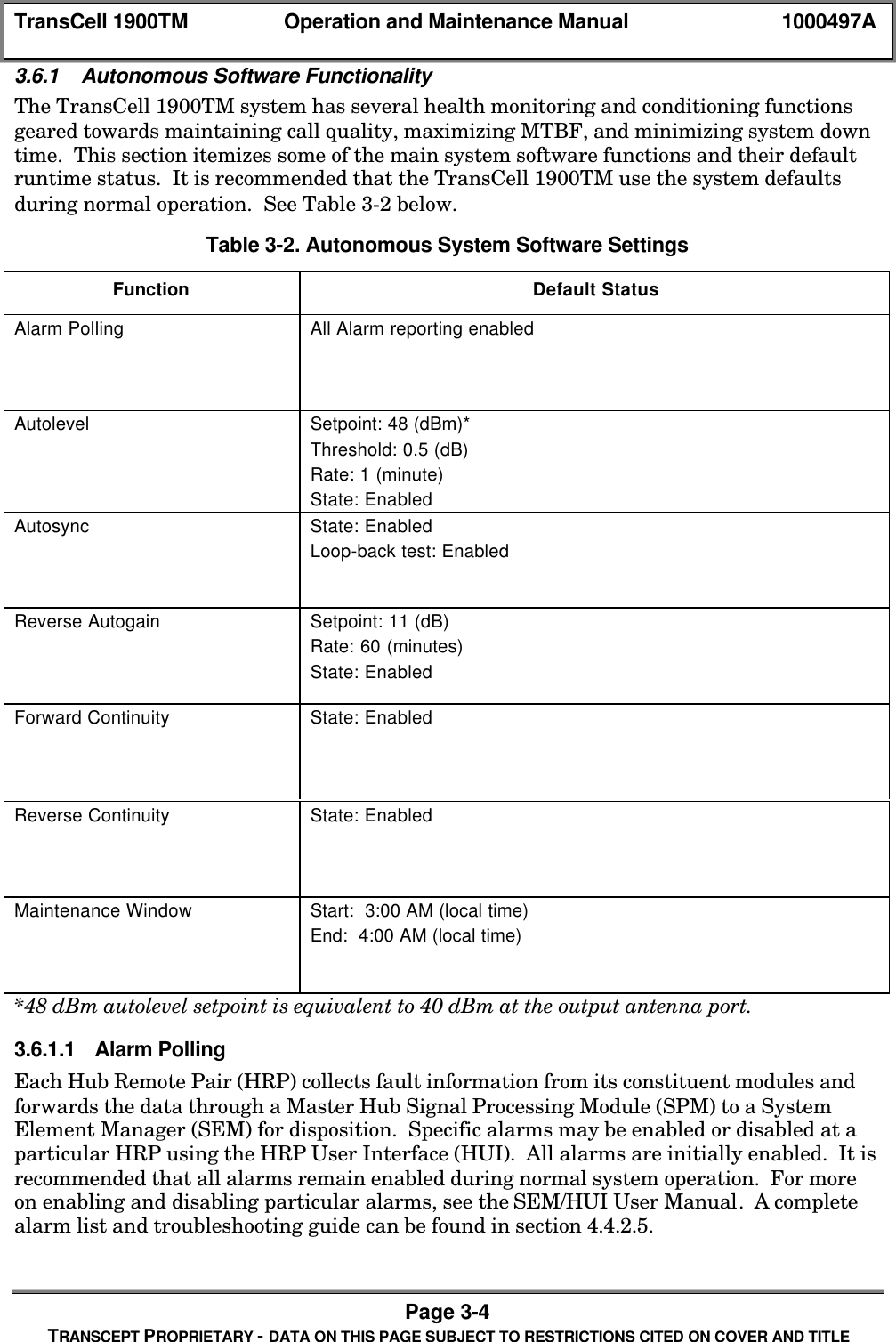
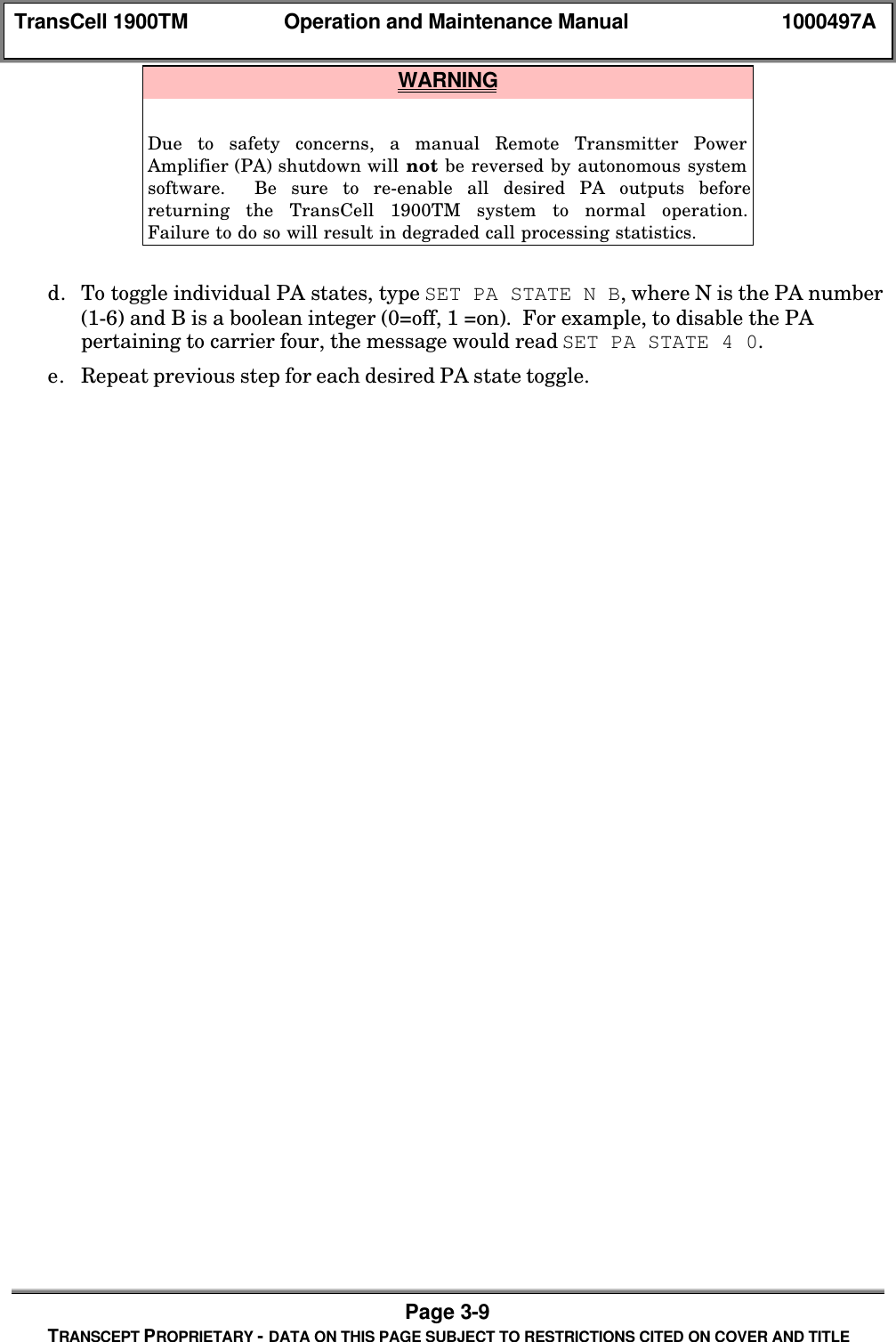
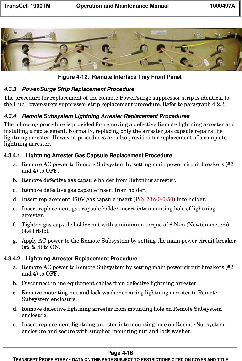
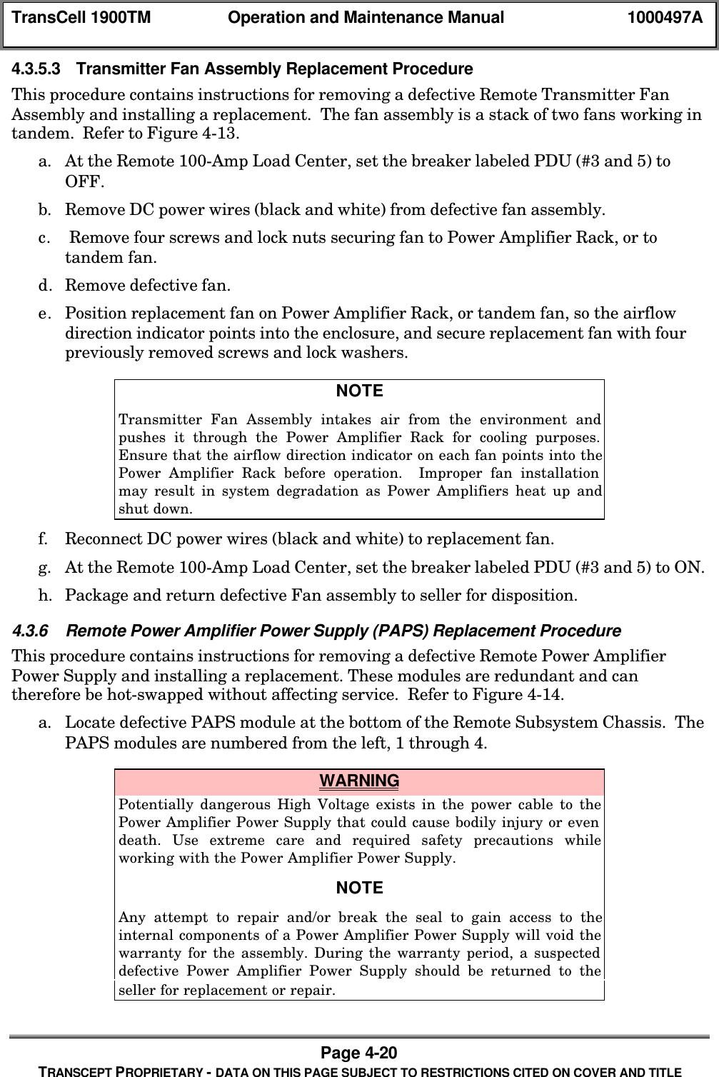
![TransCell 1900TM Operation and Maintenance Manual 1000497APage 4-25TRANSCEPT PROPRIETARY - DATA ON THIS PAGE SUBJECT TO RESTRICTIONS CITED ON COVER AND TITLE[14] Prim Test Tone Fault[15] Div Test Tone FaultRTM [0] No I2C Comms Fault[1] 303_0 Fault 1700 PLL (All Forward)[2] 303_1 Fault 224 PLL[3] 304 Fault 1700 PLL (Some Forward)[4] 313_0 Fault 1700 PLL (Prime AND Div)[5] 313_1 Fault 173 PLL[6] 314 Fault 1700 PLL (Prim OR Div)[7] 315_0 Fault 44 MHz PLL[8] 315_1 Fault All RTM PLLs[9] 361_HI Fault High Temp[10] 361_LO Fault Low Temp[11] No Acceptable Freq Plan Fault[12] Check DCCH FaultRAGC4.4.2.2 Alarm DisplaysThe user interface at the SEM workstation displays both new and closed alarms. A user isable to view all active (open) alarms via the Active Alarms display. The Logged Alarmsdisplay can be used to view a single alarm file or the last 400 logged (closed) alarms inchronological order. The severity of the alarms is categorized using the following color-coding scheme:♦ Red: Critical Alarm - Loss of service on multiple HRPs♦ Yellow: Major Alarm - Loss of service on a single HRP♦ Blue: Minor Alarm - Possible loss of service in the near future and/or degradationin performance♦ White: Informational/Other - Abnormal event detected, not currently affectingservice♦ Green: Unalarmed - No alarms detected4.4.2.3 Alarm ReportingAlarms (both new and closed alarms) are reported on an unsolicited basis. Alarm events arereported to the SEM via TCP/IP from the SPM. Alarm events are reported to the MSC viaTCP/IP from the SEM Alarm Port. The alarm format is shown below and each formatelement is described in Table 4-.<HRPID><\t><DATE><space><TIME><\t><STATUS><\t><ALARMNUMBER><\t><ALARM NAME><\t><FAULT NUMBER><\t><ALARM DETAILS><\t><SEVERITY><\t><CARRIER ID><\t><CLOSABLE><\t><IP ADDRESS>](https://usermanual.wiki/OpenCell/TCELL1900TM.Exhibit-D-users-maunal-part-2/User-Guide-150763-Page-85.png)