Opticon Sensors Europe OPN2006 Data collector User Manual SS11017 OPN 2004 ENG1
Opticon Sensors Europe BV Data collector SS11017 OPN 2004 ENG1
UserManual.wiki
>
Opticon Sensors Europe
>
OPN2006 User Manual
User Manual
Navigation menu
Upload a User Manual
Namespaces
Wiki Guide
HTML
PDF
Info
Views
User Manual
Discussion / Help
Navigation

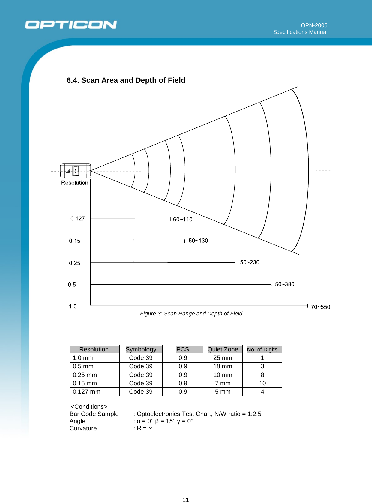
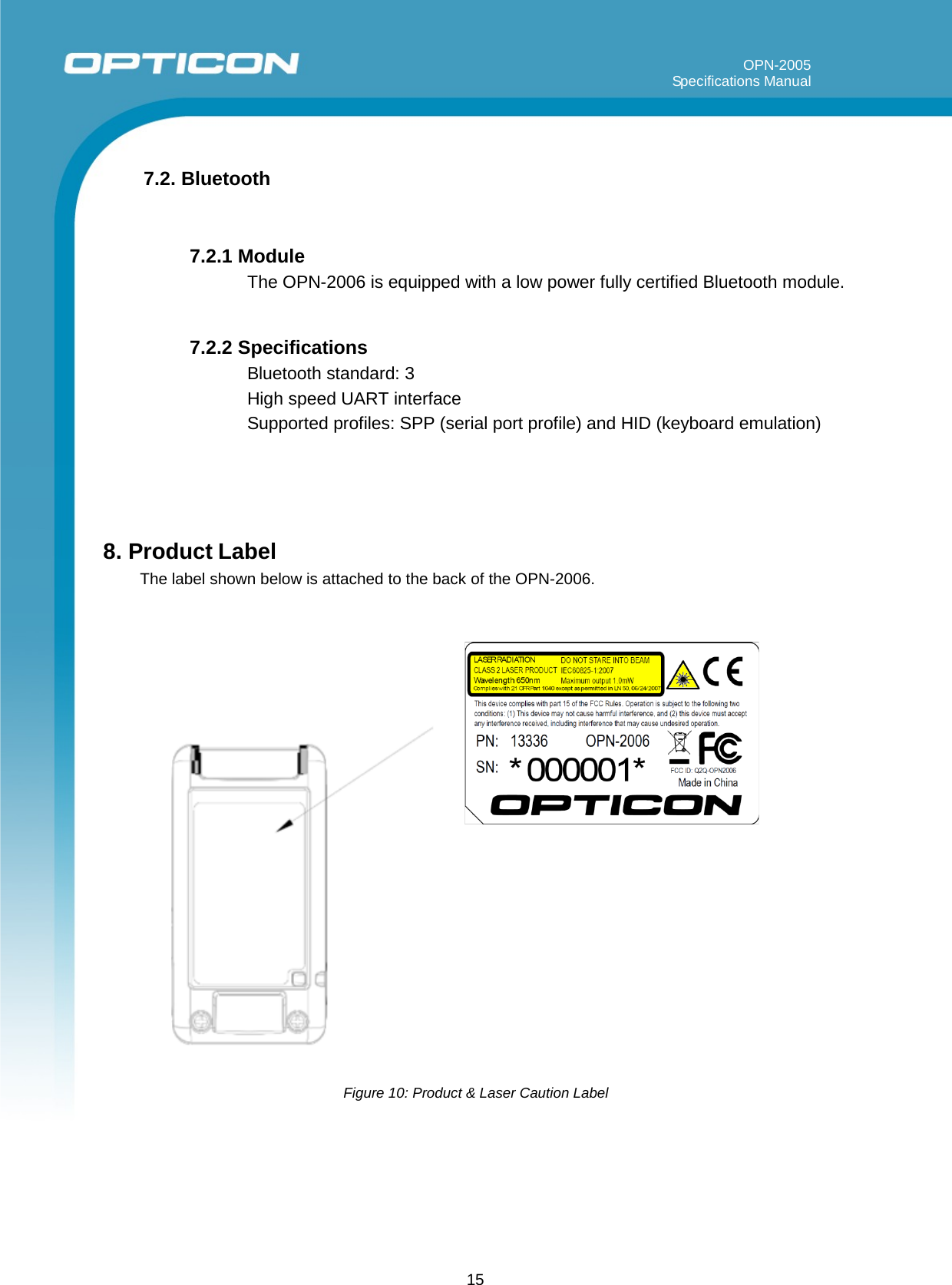
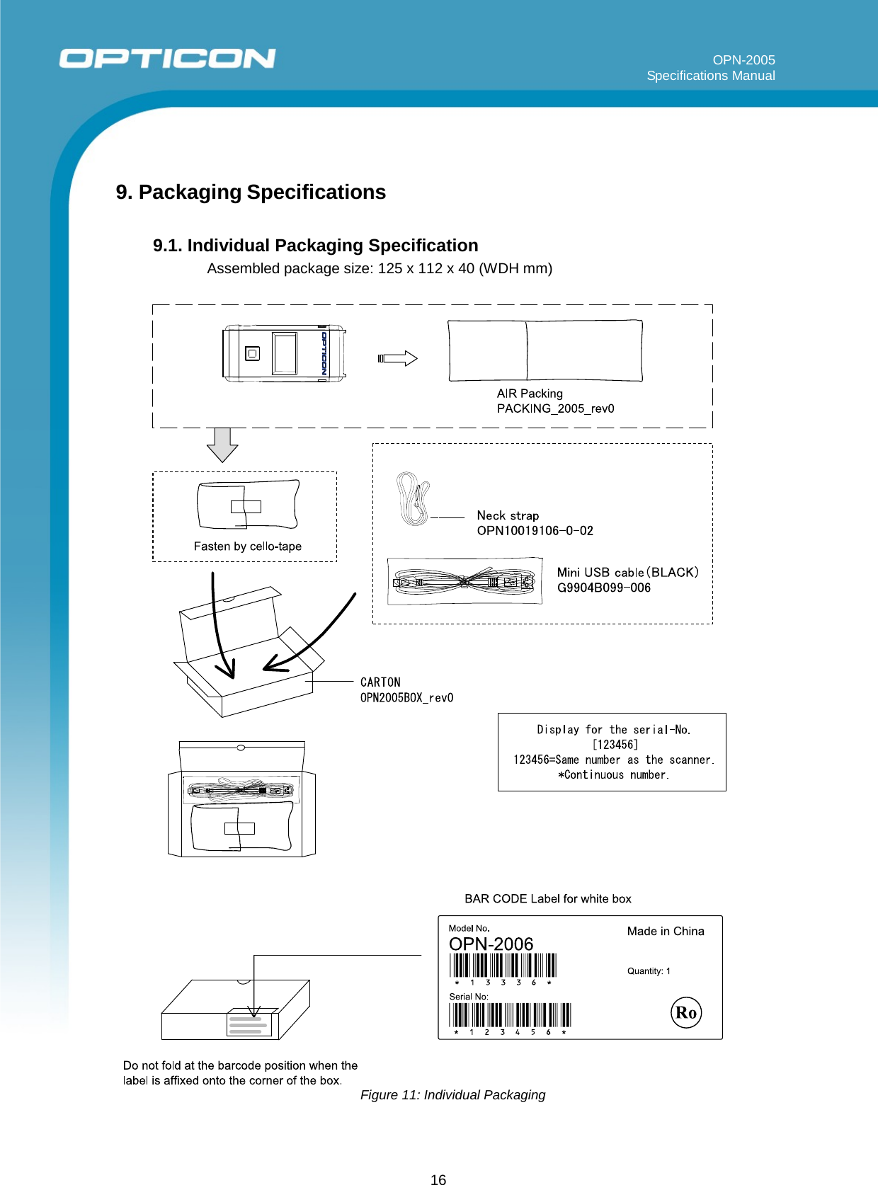
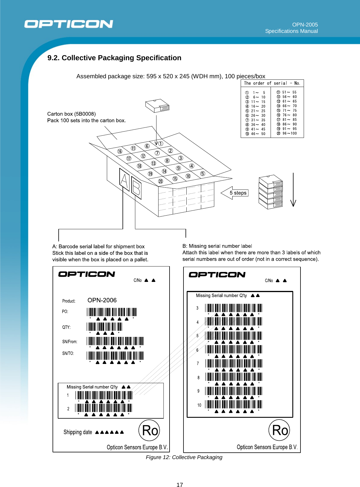
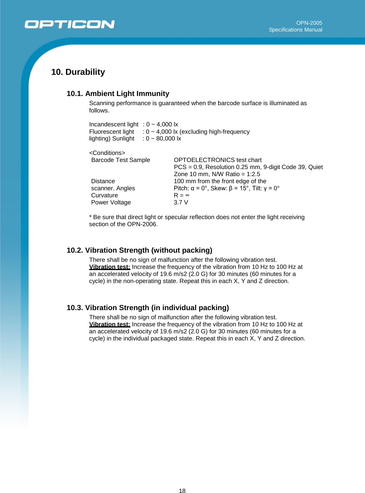
![19 OPN-2005 Specifications Manual 10.4. Drop Impact Strength (without packaging) There shall be no sign of malfunction after the following drop test. Drop test: Drop the scanner 3 times (18 times in total), at each 6 face, from a height of 150 cm onto a concrete floor as shown below. Figure 13: Drop Test 10.5. Electrostatic Discharge Immunity Air discharge: 8 kV Max. (No malfunction) 15 kV Max. (No destruction) Contact discharge: 4 kV Max. (No malfunction) [Discharged from the frame of the USB connector.] 10 kV Max. (No destruction) Measurement environment: Use electrostatic testing device compliant with IEC 61000-4-2 Discharge resistance: 330 Ω Capacitor charging: 150 pF 10.6. MTBF MTBF (Mean Time Between Failures) 30,000 hours (excluding the following parts) Laser diode : 10,000 hours Mirror scan unit : 10,000 hours150 cm](https://usermanual.wiki/Opticon-Sensors-Europe/OPN2006/User-Guide-2281725-Page-19.png)