Opticon Sensors Europe OPN2006 Data collector User Manual SS11017 OPN 2004 ENG1
Opticon Sensors Europe BV Data collector SS11017 OPN 2004 ENG1
User Manual
OPN-2006
Specifications Manual
This
manual
provides specifications
for the OPN-
2006
ultra
compact data
collector.

2
OPN-2006
Specifications Manual
All information subject to change without notice.
Document History
Model Number: OPN-2006 Specification Number: P1402160
Edition: 1.0 Original Spec Number: -
Date: 2014-02-16
Copyright 2014 Opticon. All rights reserved.
This manual may not, in whole or in part, be copied, photocopied, reproduced, translated or converted to any
electronic or machine readable form without prior written consent of Opticon.
Limited Warranty and Disclaimers
PLEASE READ THIS MANUAL CAREFULLY BEFORE INSTALLING OR USING THE
PRODUCT.
Serial Number
A serial number appears on all Opticon products. This official registration number is directly related to the device
purchased. Do not remove the serial number from your Opticon device. Removing the serial number voids the
warranty.
Warranty
Unless otherwise agreed in a written contract, all Opticon products are warranted against defects in materials and
workmanship for two years after purchase. Opticon will repair or, at its option, replace products that are defective
in materials or workmanship with proper use during the warranty period. Opticon is not liable for damages caused
by modifications made by a customer. In such cases, standard repair charges will apply. If a product is returned
under warranty and no defect is found, standard repair charges will apply. Opticon assumes no liability for any
direct, indirect, consequential or incidental damages arising out of use or inability to use both the hardware and
software, even if Opticon has been informed about the possibility of such damages.
Packaging
The packing materials are recyclable. We recommend that you save all packing material to use should you need
to transport your scanner or send it for service. Damage caused by improper packaging during shipment is not
covered by the warranty.
Trademarks
Trademarks used are the property of their respective owners.
Opticon Inc. and Opticon Sensors Europe B.V. are wholly owned subsidiaries of OPTOELECTRONICS Co., Ltd.,
12-17, Tsukagoshi 4-chome, Warabi-shi, Saitama, Japan 335-0002. TEL +81-(0) 48-446-1183; FAX +81-(0) 48-
446-1184
SUPPORT
USA Europe
Phone: 800-636-0090
Email: support@opticonusa.com Email: support@opticon.com
Web: www.opticonusa.com Web: www.opticon.com

3
OPN-2006
Specifications Manual
Revision History
Specification No. : P1402160
Product name : OPN-2006
Edition Date Page Section Description of Changes
First 2014/02/16 - - Initial release

4
OPN-2005
Specifications Manual
Contents
1. Abstract ................................................................................................................................. 6
2. Overview ............................................................................................................................... 6
2.1. Product / Model Name ..................................................................................................... 6
2.2. Features .......................................................................................................................... 6
3. Basic Specifications ............................................................................................................. 7
4. Detailed View ........................................................................................................................ 8
5. Optical Specifications .......................................................................................................... 9
5.1. Laser Scanning Specifications ......................................................................................... 9
5.2. Laser Scanning Standards ............................................................................................... 9
5.2.1. Laser Scanning Tilt .................................................................................................... 9
5.2.2. Laser Scanning Curvature ......................................................................................... 9
6. Technical Specifications Barcode Scanner ...................................................................... 10
6.1. Print Contrast Signal (PCS) ........................................................................................... 10
6.2. Minimum Resolution ...................................................................................................... 10
6.3. Supported symbologies: ................................................................................................ 10
6.4. Scan Area and Depth of Field ........................................................................................ 11
6.5. Pitch, Skew, and Tilt ...................................................................................................... 12
6.6. Curvature ....................................................................................................................... 13
7. Interface Specifications ..................................................................................................... 14
7.1. USB ............................................................................................................................... 14
7.1.1. Settings ................................................................................................................... 14
7.1.2. Cable ....................................................................................................................... 14
7.1.3. Connector ................................................................................................................ 14
7.1.4. Interface Circuit ....................................................................................................... 14
7.2. Bluetooth ....................................................................................................................... 15
7.2.1 Module ..................................................................................................................... 15
7.2.2 Specifications ........................................................................................................... 15
8. Product Label ..................................................................................................................... 15
9. Packaging Specifications................................................................................................... 16
9.1. Individual Packaging Specification ................................................................................. 16
9.2. Collective Packaging Specification ................................................................................. 17
10. Durability ........................................................................................................................... 18

5
OPN-2005
Specifications Manual
10.1. Ambient Light Immunity ............................................................................................... 18
10.2. Vibration Strength (without packing) ............................................................................ 18
10.3. Vibration Strength (in individual packing) ..................................................................... 18
10.4. Drop Impact Strength (without packaging) ................................................................... 19
10.5. Electrostatic Discharge Immunity ................................................................................. 19
10.6. MTBF ........................................................................................................................... 19
11. Regulatory
Compliance
.................................................................................................... 20
11.1. Laser Safety ............................................................................................................... 20
11.2. EMC ........................................................................................................................... 20
12. RoHS ................................................................................................................................. 20
13. Precautions ....................................................................................................................... 21
13.1. Precaution against Laser Light ..................................................................................... 21
13.2. Handling ...................................................................................................................... 21
Appendix 1: Mechanical Drawing .......................................................................................... 22
Table of Figures
Figure 1: Detailed View .............................................................................................................. 8
Figure 2: Laser Scanning Tilt and Curvature .............................................................................. 9
Figure 3: Scan Range and Depth of Field ................................................................................. 11
Figure 4: Pitch .......................................................................................................................... 12
Figure 5: Skew ......................................................................................................................... 13
Figure 6: Tilt ............................................................................................................................. 13
Figure 7: Curvature .................................................................................................................. 13
Figure 8: USB B connector ....................................................................................................... 14
Figure 9: Interface circuit .......................................................................................................... 14
Figure 10: Product & Laser Caution Label ................................................................................ 15
Figure 11: Individual Packaging .................................................. Error! Bookmark not defined.
Figure 12: Collective Packaging ............................................................................................... 17
Figure 13: Drop Test ................................................................................................................ 19
Figure 14: Mechanical Drawing ................................................................................................ 22

6
OPN-2005
Specifications Manual
1. Abstract
This manual provides specifications for the OPN-2006 ultra compact data collector.
2. Overview
OPN-2006 has a built in compact laser scanner and scanned barcode data output occurs via USB
interface or Bluetooth. This product is compliant with RoHS.
2.1. Product / Model Name
OPN-2006
2.2. Features
・ The OPN-2006 is handy and simple data collector.
・ Its compact, lightweight design makes it easy to take anywhere.
・ Data transmission is performed via Bluetooth or a USB interface.
・ Power supply is 3.7V, 240 mAh and lithium-ion polymer battery is used.
・ The OPN-2006 is charged from a USB interface of the host computer.
7
OPN-2005
Specifications Manual
3. Basic Specifications
Item Specification Remarks
Control Section
CPU 32 bit
Clock 96 MHz
FROM 512 Kbyte + 32 Kbyte
SRAM 96 Kbyte
Storage FROM 1 Mbyte
Input Section Key type 2 keys: Trigger, Function
Indication LED 2 multicolor color LEDs (red, green, orange, blue)
Buzzer Volume (3 levels), Adjustable tone
USB Mini USB ver 1.1
12 Mbps, USB-
COM/USB-HID
RTC (clock)
Supported
Year, month, date, hour,
minute, second (accuracy: ± 90
seconds per month)
Power Supply
Main battery Lithium polymer 240 mAh
Continuous operating
time
1000 scans or more
Condition: read
twice in 10 secs.
at room temp.
Scanner
(MSL-2001)
Light-emitting
element
Red laser diode
Laser wavelength
/ output
650 ±10 nm, up to 1 mW, 25°C
Scanning frequency 100 ±20 scan / sec
Minimum resolution 0.127mm
Scanning distance 60 ~ 250mm
Resolution: 1.0
mm PCS 0.9
Symbology
JAN, EAN, UPC-A, UPC-E,
NW-7 (Codabar),Industrial 2 of 5,
Code 11, Code 39, Code 93,
Code 128, GS1 Data Bar etc.
Dimensions 62.0 × 32.0 × 16.0 (DWH mm)
Weight Approx. 29 g
Environmental
Specifications
Operating
temperature/humidity
0 ~ 40 °C
20 ~ 85 %RH
No frost,
no condensation
Storage
temperature/humidity
-20 ~ 60°C
20 ~ 85%RH
No frost,
no condensation
Drop Impact
Strength (*1)
Frequency 6 faces, 3 cycles
Height 150 cm
Floor Concrete
Regulatory
Compliance
Laser safety:
IEC60825-1:2007
CE Marking, FCC
*1 : Conditions of drop shock resistance
- Scratches or whitening on plastic surface shall not be counted as a malfunction.
- The product shall work properly after the drop test.
8
OPN-2005
Specifications Manual
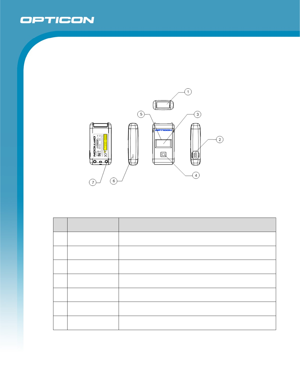
4. Detailed View
Figure 1: Detailed View
No. Name
Description
1 Scanning Window Laser light is emitted through this window to read bar codes.
2 Mini USB connector Used to connect a dedicated USB cable for charging & data
communication
3 Trigger Key A trigger key used to read bar codes
4 Function Key A function key that can be configured with application
5 LED Indicator of operating status, such as bar code reading and
warnings
6 Buzzer Hole Sound from a built-in buzzer comes out through these holes.
7 Strap Hole A hole to attach a hand strap
9
OPN-2005
Specifications Manual
5. Optical Specifications
5.1. Laser Scanning Specifications
Item Characteristics Unit
Light-Emitting Element Red laser diode -
Emission Wavelength 650 ±10 (25° C) nm
Light Output 1.0 or less mW
Scanning Method Bi-directional scanning -
Scanning Speed 100 ±20 scans/sec
Scan Angle Scan Angle 54 ±5 deg
Read angle 44 (Min) deg
Notes:
Refer to “Technical Specifications,” to read about scanning performance.
5.2. Laser Scanning Standards
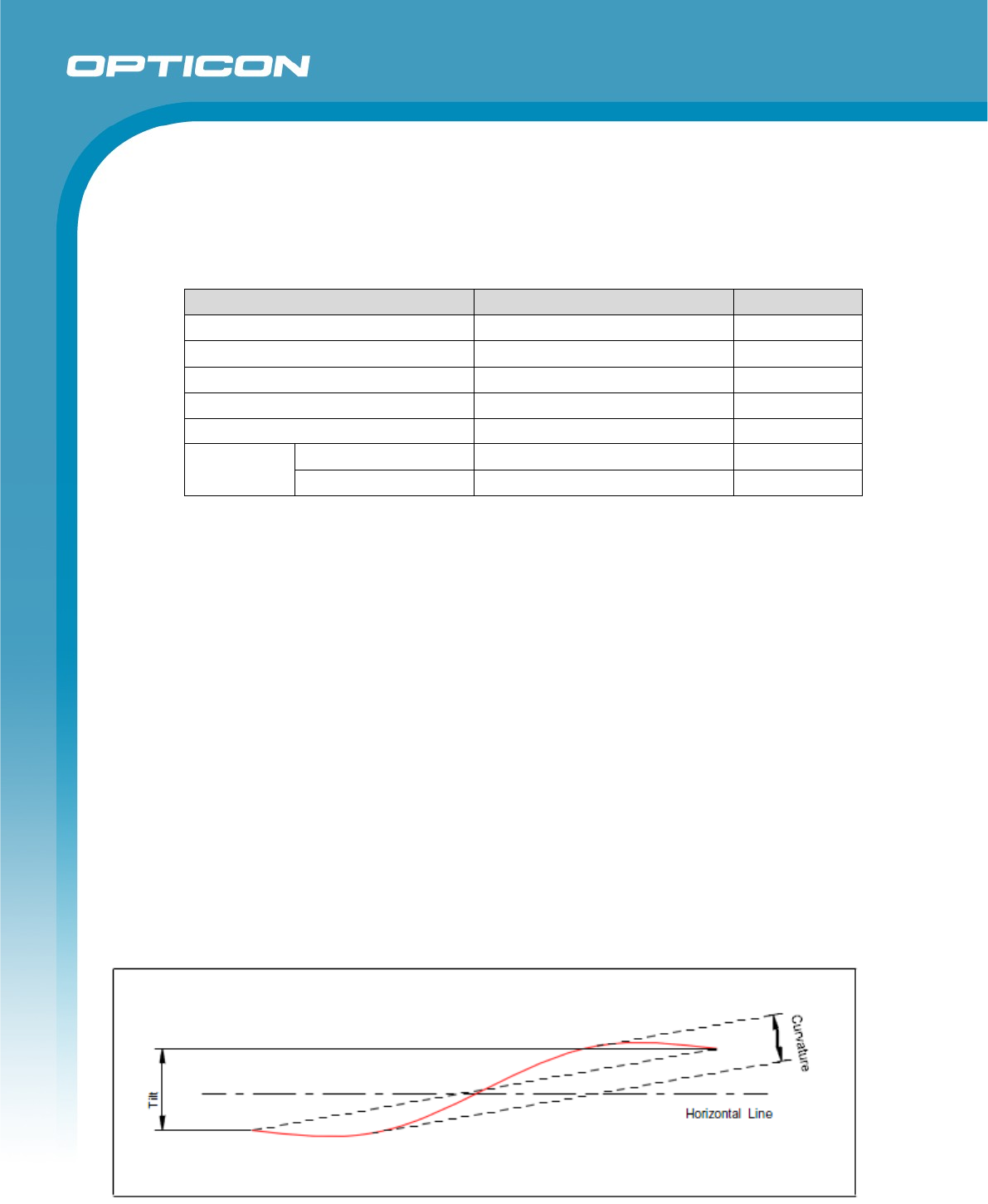
5.2.1. Laser Scanning Tilt
Vertical differences between both ends of a laser scanning line:
- Up to 0.92 degrees in a vertical direction from the scan origin (scanning mirror).
- Up to 2.46 mm measured at 150 mm from the scan origin and with zero skew angle.
- Measured in the middle of the scan line.
5.2.2. Laser Scanning Curvature
The maximum differences between the laser scanning line and a straight line connecting
the both ends of the scanning line:
- Up to 1.17 degrees from the scan origin (scanning mirror).
- Up to 3.06 mm measured at 150 mm from the scan origin with zero skew angle.
- Measured in the middle of the scan line.
Figure 2: Laser Scanning Tilt and Curvature

10
OPN-2005
Specifications Manual
6. Technical Specifications Barcode Scanner
The conditions are as follows, unless otherwise specified.
Conditions
Ambient temperature and Room temperature (20º C)
humidity: Room humidity (45% to 85% RH)
Ambient light: 500 to 900 lx
Background: Barcode = black
Space = white
Margin = white
Background of label = black
Decoding test: Approve the performance when decoding is successful in all ten
tests. (Decoding is deemed successful when completed in 0.5
seconds or less.)
6.1. Print Contrast Signal (PCS)
PSC 0.45 or higher (70% or higher reflectivity of space and quiet zone)
PCS = Reflectance of white bar-Reflectance of black bar
Reflectance of white bar
6.2. Minimum Resolution
0.127 mm
6.3. Supported symbologies:
Linear (1D)
JAN/UPC/EAN, incl. add-on S-Code
Codabar/NW-7 Telepen
Code 11 Tri-Optic
Code 39 UK/Plessey
Code 93
Code 128 Postal codes (1D)
GS1-128 (EAN-128) Chinese Post
GS1 Databar (RSS) Korean Postal Authority Code
IATA
Industrial 2of5 2D codes
Interleaved 2of5 GS1 Composite Codes
ISBN-ISMN-ISSN
Matrix 2of5
MSI/Plessey
11
OPN-2005
Specifications Manual
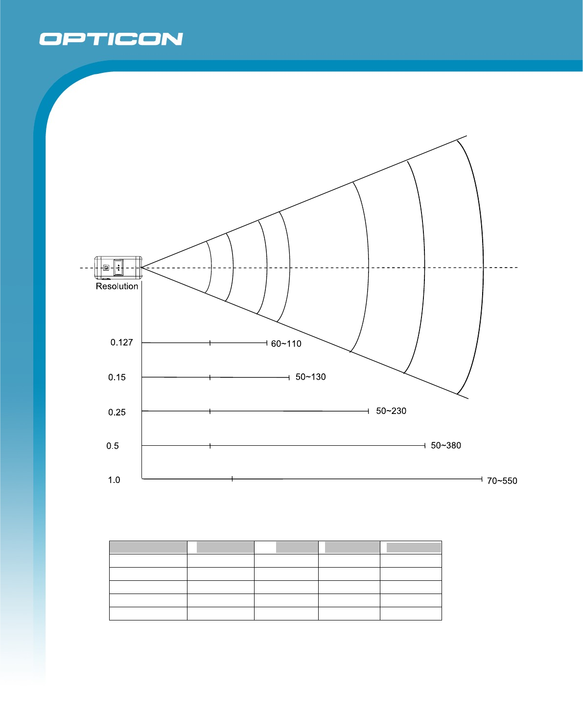
6.4. Scan Area and Depth of Field
Figure 3: Scan Range and Depth of Field
Resolution
Symbology
PCS
Quiet Zone
No.
of
Digits
1.0 mm Code 39 0.9 25 mm 1
0.5 mm
Code 39
0.9
18 mm
3
0.25 mm Code 39 0.9 10 mm 8
0.15 mm
Code 39
0.9
7 mm
10
0.127 mm Code 39 0.9 5 mm 4
<Conditions>
Bar Code Sample : Optoelectronics Test Chart, N/W ratio = 1:2.5
Angle : α = 0° β = 15° γ = 0°
Curvature : R = ∞
12
OPN-2005
Specifications Manual
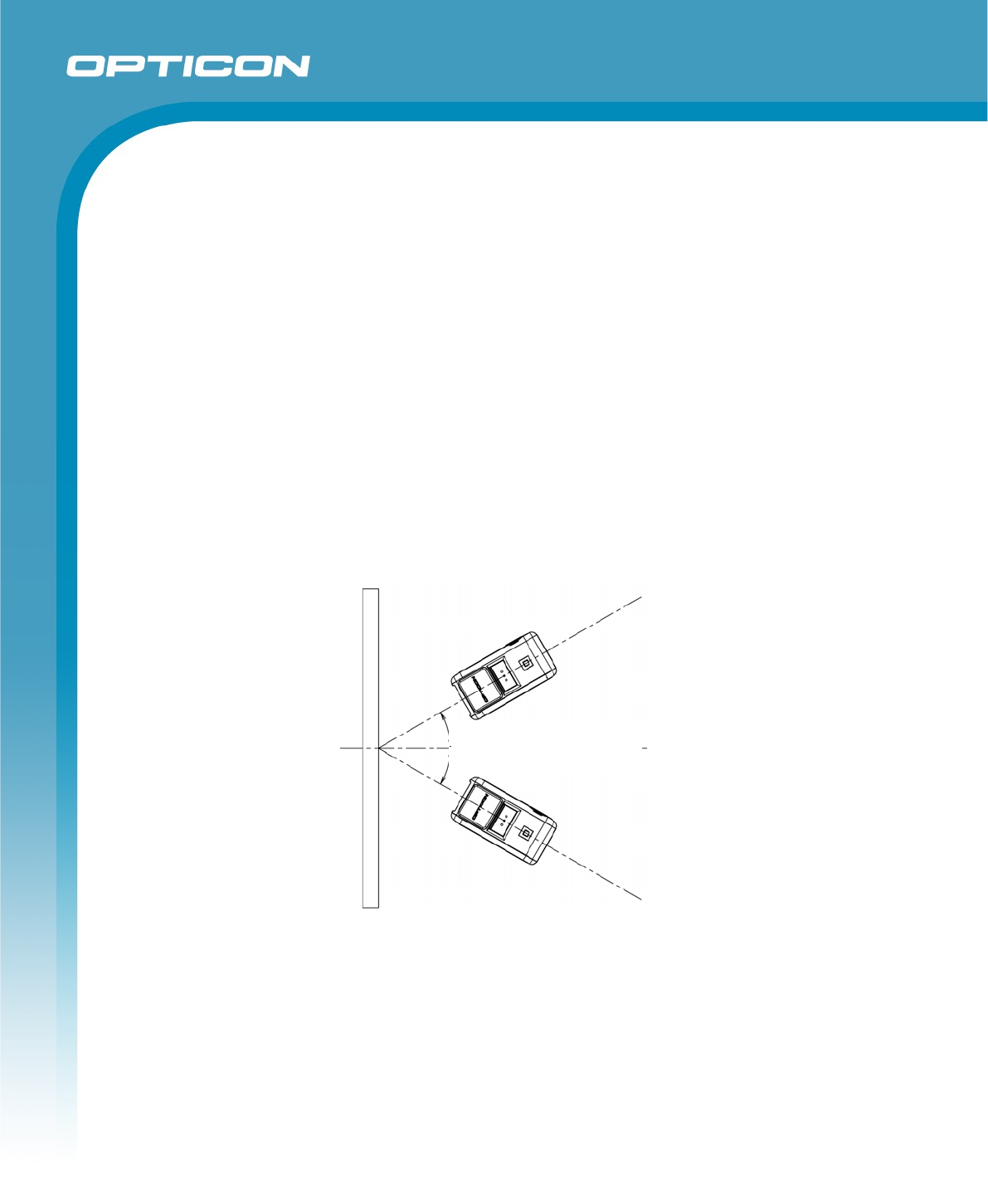
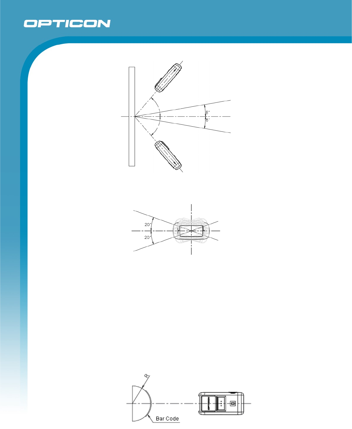
6.5. Pitch, Skew, and Tilt
Pitch : α ≦ ±35°
Skew : β ≦ ±50° (Excluding dead zone)
Dead Zone : β ≦ ±8 ° (Decoding may fail in some areas as a result of specular reflection)
Tilt : γ ≦ ±20°
Conditions
Bar Code Sample Optoelectronics Test Sample
Distance 110 mm from the edge of the OPN-2006
<Pitch, Skew and Dead Zone>
PCS 0.9, Resolution 0.25 mm, 9-digit Code 39,
Quiet Zone 10 mm, N/W Ratio = 1 : 2.5
<Tilt>
PCS 0.9, Resolution 0.5 mm, 3-digit Code 39, Quiet Zone 15 mm
Angle Pitch and Tilt angles calculated with Skew angle β= +15°
Skew angle / Dead zone: α = 0°, γ = 0°
Curvature R = ∞
Figure 4: Pitch
25o
25o
13
OPN-2005
Specifications Manual
Figure 5: Skew
Figure 6: Tilt
6.6. Curvature
With 8-digit JAN/UPC/EAN barcodes, decoding performance is guaranteed when R ≧ 15 mm
With 13-digit JAN/UPC/EAN barcodes, decoding performance is guaranteed when R ≧ 20 mm
Conditions
Bar Code Sample Optoelectronics Test Sample
PCS 0.9, Resolution 0.26 mm, Quiet Zone 10 mm
Distance 110 mm from the edge of the scanner
Angle Skew angle β = +15
Figure 7: Curvature
40
o
40
o
14
OPN-2005
Specifications Manual
7. Interface Specifications
7.1. USB
7.1.1. Settings
The interface is full-speed USB.
7.1.2. Cable
Dedicated cable with PC connector is provided.
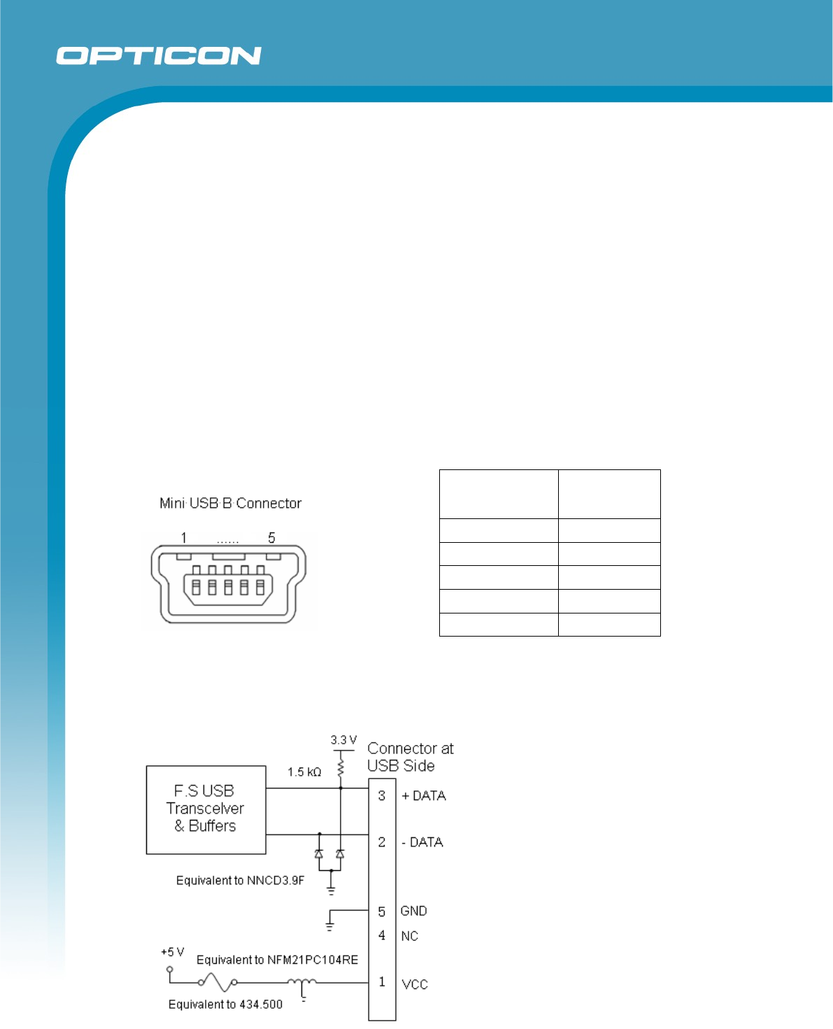
7.1.3. Connector
Figure 8: USB B connector
7.1.4. Interface Circuit
Figure 9: Interface circuit
Contact
Number
Signal Name
1
VCC
2
-DATA
3
+DATA
4
NC
5
GND
15
OPN-2005
Specifications Manual
7.2. Bluetooth
7.2.1 Module
The OPN-2006 is equipped with a low power fully certified Bluetooth module.
7.2.2 Specifications
Bluetooth standard: 3
High speed UART interface
Supported profiles: SPP (serial port profile) and HID (keyboard emulation)
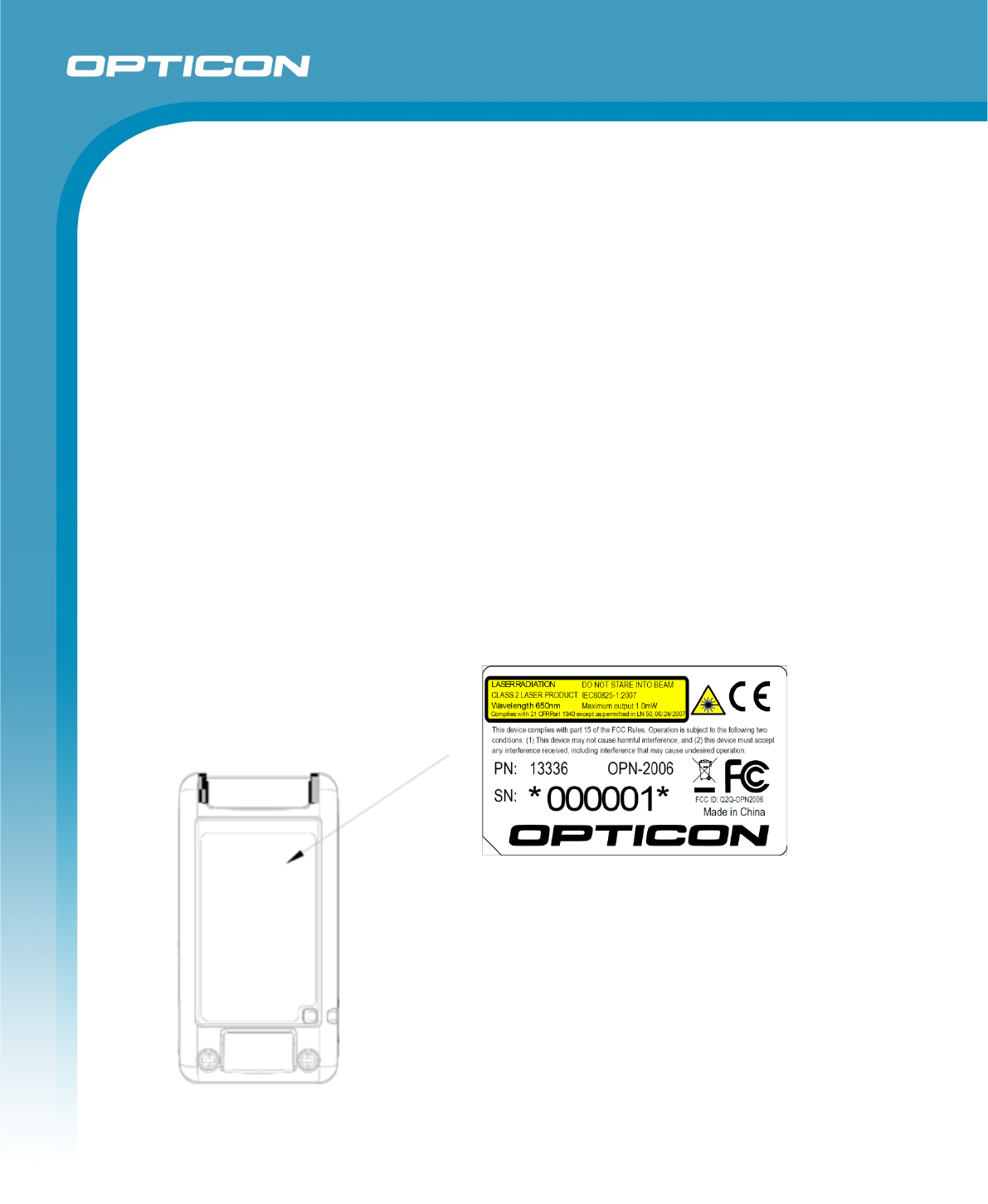
8. Product Label
The label shown below is attached to the back of the OPN-2006.
Figure 10: Product & Laser Caution Label
16
OPN-2005
Specifications Manual
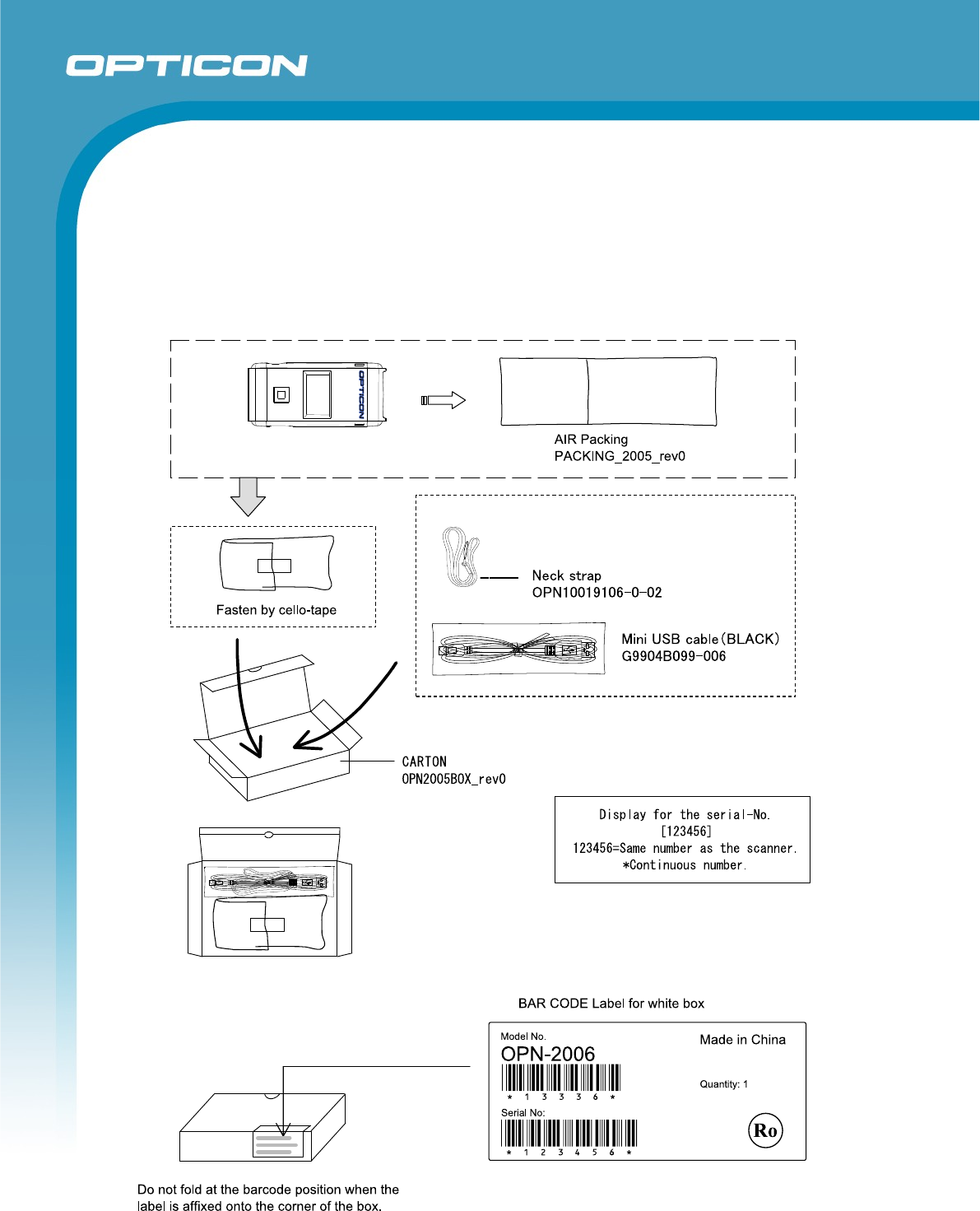
9. Packaging Specifications
9.1. Individual Packaging Specification
Assembled package size: 125 x 112 x 40 (WDH mm)
Figure 11: Individual Packaging
17
OPN-2005
Specifications Manual
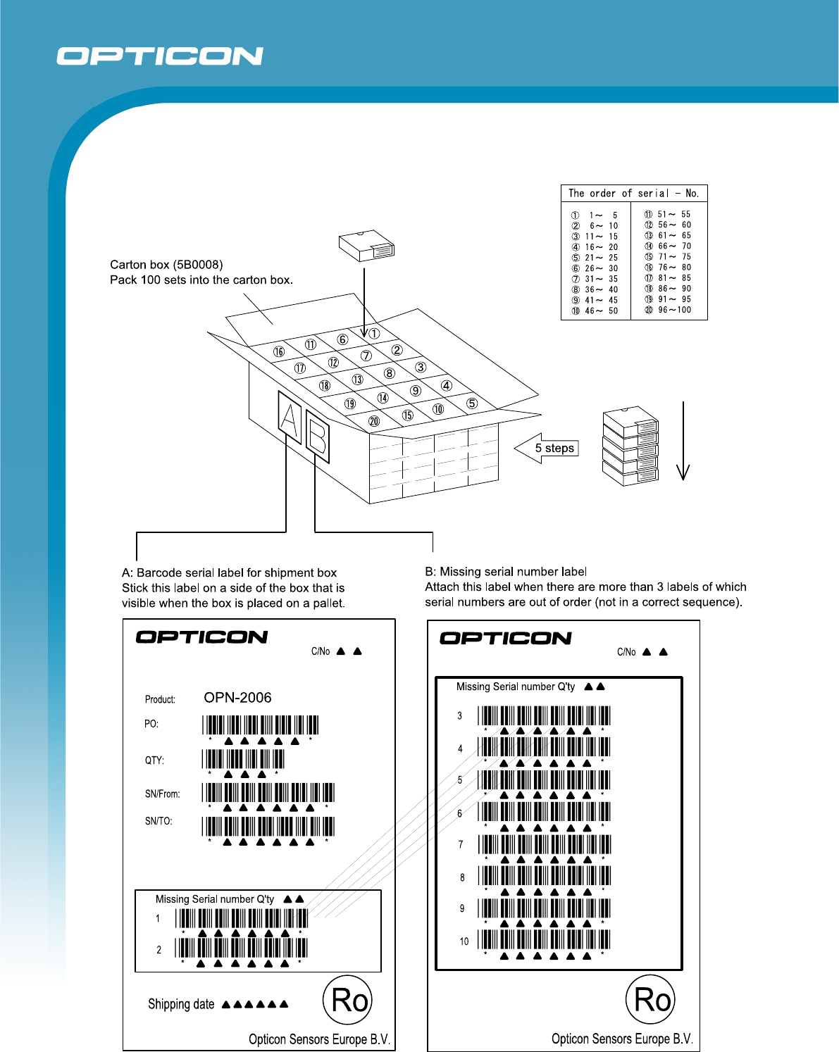
9.2. Collective Packaging Specification
Assembled package size: 595 x 520 x 245 (WDH mm), 100 pieces/box
Figure 12: Collective Packaging

18
OPN-2005
Specifications Manual
10. Durability
10.1. Ambient Light Immunity
Scanning performance is guaranteed when the barcode surface is illuminated as
follows.
Incandescent light : 0 ~ 4,000 lx
Fluorescent light : 0 ~ 4,000 lx (excluding high-frequency
lighting) Sunlight : 0 ~ 80,000 lx
<Conditions>
Barcode Test Sample OPTOELECTRONICS test chart
PCS = 0.9, Resolution 0.25 mm, 9-digit Code 39, Quiet
Zone 10 mm, N/W Ratio = 1:2.5
Distance 100 mm from the front edge of the
scanner. Angles Pitch: α = 0°, Skew: β = 15°, Tilt: γ = 0°
Curvature R = ∞
Power Voltage 3.7 V
* Be sure that direct light or specular reflection does not enter the light receiving
section of the OPN-2006.
10.2. Vibration Strength (without packing)
There shall be no sign of malfunction after the following vibration test.
Vibration test: Increase the frequency of the vibration from 10 Hz to 100 Hz at
an accelerated velocity of 19.6 m/s2 (2.0 G) for 30 minutes (60 minutes for a
cycle) in the non-operating state. Repeat this in each X, Y and Z direction.
10.3. Vibration Strength (in individual packing)
There shall be no sign of malfunction after the following vibration test.
Vibration test: Increase the frequency of the vibration from 10 Hz to 100 Hz at
an accelerated velocity of 19.6 m/s2 (2.0 G) for 30 minutes (60 minutes for a
cycle) in the individual packaged state. Repeat this in each X, Y and Z direction.
19
OPN-2005
Specifications Manual
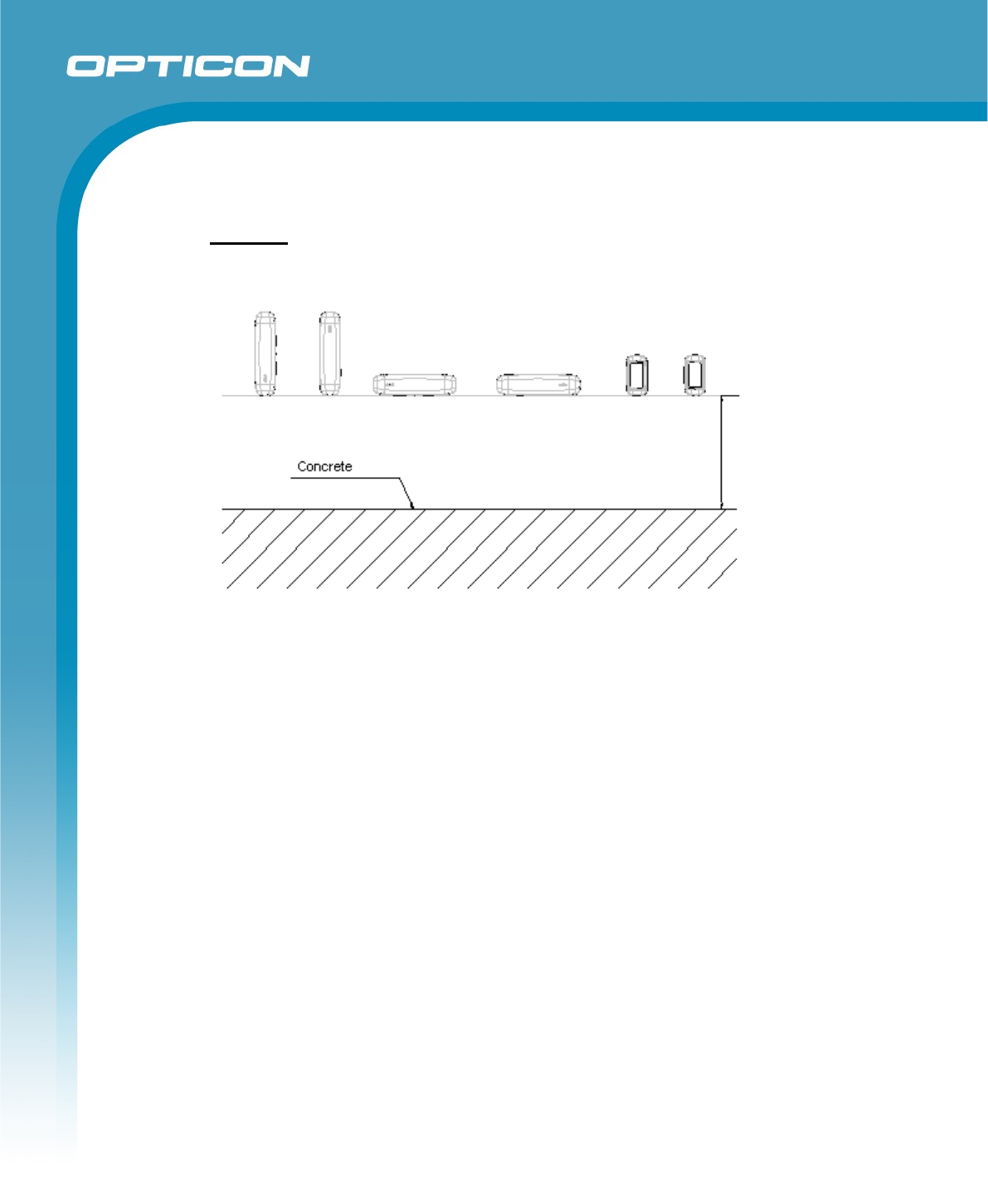
10.4. Drop Impact Strength (without packaging)
There shall be no sign of malfunction after the following drop test.
Drop test: Drop the scanner 3 times (18 times in total), at each 6 face, from a height of
150 cm onto a concrete floor as shown below.
Figure 13: Drop Test
10.5. Electrostatic Discharge Immunity
Air discharge: 8 kV Max. (No malfunction)
15 kV Max. (No destruction)
Contact discharge: 4 kV Max. (No malfunction) [Discharged from the frame of the
USB connector.]
10 kV Max. (No destruction)
Measurement
environment: Use electrostatic testing device compliant with IEC 61000-4-2
Discharge
resistance:
330 Ω
Capacitor charging: 150 pF
10.6. MTBF
MTBF (Mean Time Between Failures) 30,000 hours (excluding the following parts)
Laser diode : 10,000 hours
Mirror scan unit : 10,000 hours
150 cm

OPN-2005
Specifications Manual
20
11. Regulatory
Compliance
11.1. Laser Safety
IEC 60825-1 Ed.2: 2007 Class 2
CDRH ClassⅡ
11.2. EMC
EN55022
EN55024
FCC Part 15 Subpart B Class B
This device complies with part 15 of the FCC Rules. Operation is subject To the following two
conditions: ( 1 ) this device may not cause harmful Interference, and ( 2 ) this device must accept
any interference received, including interference that may cause undesired operation.
15.21
You are cautioned that changes or modifications not expressly approved by the part
responsible for compliance could void the user’s authority to operate the equipment.
15.105(b)
This equipment has been tested and found to comply with the limits for a Class B digital
device, pursuant to part 15 of the FCC rules. These limits are designed to provide
reasonable protection against harmful interference in a residential installation. This
equipment generates uses and can radiate radio frequency energy and, if not installed
and used in accordance with the instructions, may cause harmful interference to radio
communications. However, there is no guarantee that interference will not occur in a
particular installation. If this equipment does cause harmful interference to radio or
television reception, which can be determined by turning the equipment off and on, the
user is encouraged to try to correct the interference by one or more of the following
measures:
- Reorient or relocate the receiving antenna.
- Increase the separation between the equipment and receiver.
- Connect the equipment into an outlet on a circuit different from that to which the receiver
is connected.
- Consult the dealer or an experienced radio/TV technician for help.
12. RoHS
The OPN-2006 is compliant with RoHS.
RoHS: The restriction of the use of certain hazardous substances in electrical and electronic
equipment, 2002/95/EC
OPN-2005
Specifications Manual
21
13. Precautions
13.1. Precaution against Laser Light
*Use of controls or adjustments or performance of procedures other than those specified
herein may result in hazardous radiation exposure.
Caution - Do not stare into the laser light from a scanning window. It may harm your eyes.
Do not point the laser directly at others’ eyes. It may harm your eyes.
Do not stare into the beam with optical instruments. It may harm your eyes.
13.2. Handling
Handle this product carefully. Do not deliberately subject it to any of the following:
(1) Shock:
・ Do not drop this product from a height greater than specified in this manual.
・ Do not place this product under or between any heavy items.
・ Do not swing this product around holding the hand strap.
(2) Temperature Conditions:
・ Do not use this product at temperatures outside the specified range.
・ Do not pour boiling water on this product.
・ Do not throw this product into a fire.
(3) Foreign Materials:
・ Do not immerse this product in water or other liquid.
・ Do not expose this product to chemicals.
(4) Battery:
(5) Others
・ Do not disassemble this product.
・ Do not use this product near a radio or a TV. It may cause reception problems.
・ This product may be affected by a momentary voltage drop caused by lightning.
・This product may not perform properly in a place where it will be subjected to a
flickering light, such as a CRT (computer monitor, television, etc.).
* This specification manual is subject to change without prior notice.
OPN-2005
Specifications Manual
22
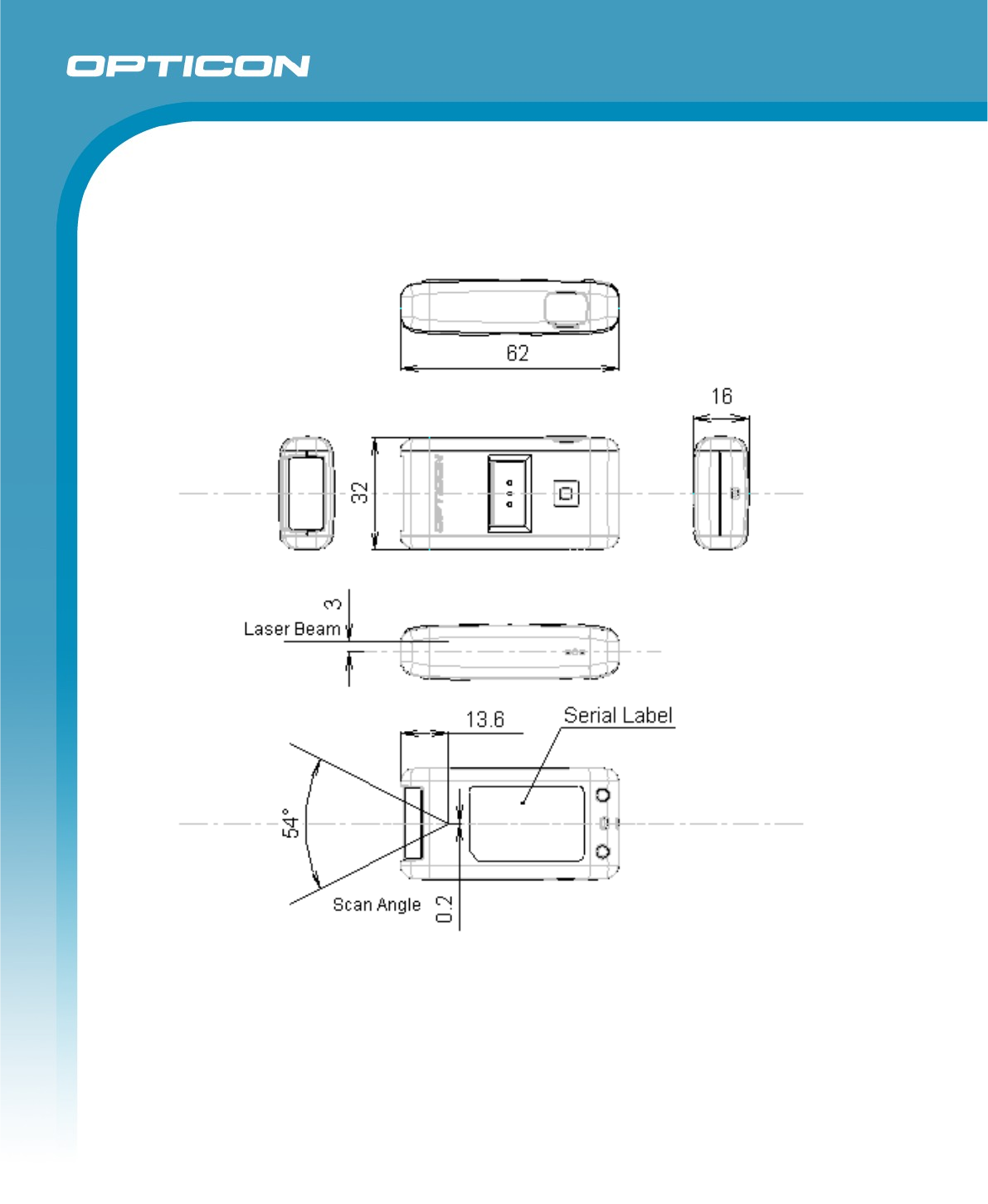
Appendix 1: Mechanical Drawing
Figure 14: Mechanical Drawing