Opticon Sensors Europe PX36 Barcode data collector User Manual
Opticon Sensors Europe BV Barcode data collector
Contents
- 1. User Manual
- 2. Manual of Cradle
User Manual
PX-36
V-1.0
1
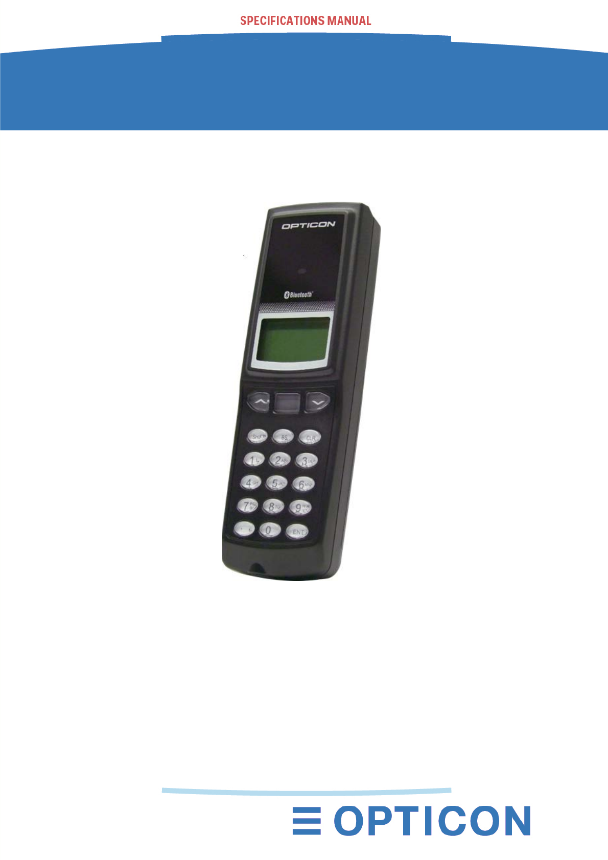
PX-36
2D Data Collector with Bluetooth
The PX-36 is a Data Collector with a 2D barcode scan engine,
Bluetooth communication and time stamp functionality.
V-1.0

PX-36
V-1.0
2
The information in this document is subject to change without notice.
Document History
Model Number: PX-36 Original release date 31-08-2015
Revision: V-1.0 Date 31-08-2015
2015 Copyright Opticon. All rights reserved.
This manual may not, in whole or in part, be copied, photocopied, reproduced, translated or converted
to any electronic or machine readable form without prior written consent of Opticon.
Limited Warranty and Disclaimers
PLEASE READ THIS MANUAL CAREFULLY BEFORE INSTALLING
OR USING THE PRODUCT.
Serial Number
A serial number appears on all Opticon products. This official registration number is directly related to
the device purchased. Do not remove the serial number from your Opticon device. Removing the
serial number voids the warranty.
Warranty
Unless otherwise agreed in a written contract, all Opticon products are warranted against defects in
materials and workmanship for two years after purchase excluding batteries. Opticon will repair or, at
its option, replace products that are defective in materials or workmanship with proper use during the
warranty period. Opticon is not liable for damages caused by modifications made by a customer. In
such cases, standard repair charges will apply. If a product is returned under warranty and no defect is
found, standard repair charges will apply. Opticon assumes no liability for any direct, indirect,
consequential or incidental damages arising out of use or inability to use both the hardware and
software, even if Opticon has been informed about the possibility of such damages.
Packaging
The packing materials are recyclable. We recommend that you save all packing material to use should
you need to transport your data collector or send it for service. Damage caused by improper
packaging during shipment is not covered by the warranty.
Trademarks
Trademarks used are the property of their respective owners.
Opticon Inc. and Opticon Sensors Europe B.V. are wholly owned subsidiaries of
OPTOELECTRONICS Co., Ltd., 12-17, Tsukagoshi 4-chome, Warabi-shi, Saitama, Japan 335-0002.
TEL +81-(0) 48-446-1183; FAX +81-(0) 48-446-1184
SUPPORT
USA Europe
Phone: 800-636-0090
Email: support@opticonusa.com Email: support@opticon.com
Web: www.opticonusa.com Web: www.opticon.com
PX-36
V-1.0
3
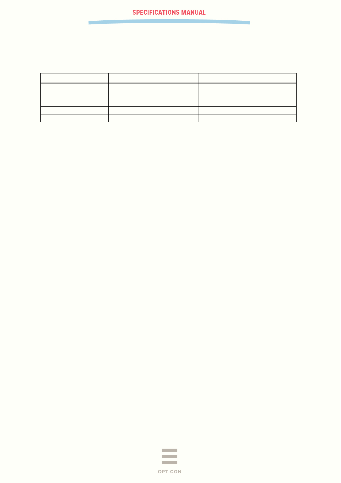
Revision History
Product Name : PX-36
Edition Date Page Section Description of Changes
First 2015/08/31 - - Initial release

PX-36
V-1.0
4
Contents
1 Abstract ........................................................................................................................ 6
2 Overview ....................................................................................................................... 6
3 Basic Specifications .................................................................................................... 7
3.1 Ambient Light Immunity conditions .......................................................................................... 9
4 Electrical Specifications ............................................................................................ 10
4.1 Main Battery ........................................................................................................................... 10
4.2 Battery Operating Time and Charging Time (TBD) ............................................................... 10
5 Mechanical .................................................................................................................. 11
5.1 Dimensions ............................................................................................................................ 11
5.2 Weight .................................................................................................................................... 11
5.3 Color ...................................................................................................................................... 11
5.4 Detailed view ......................................................................................................................... 12
6 Interface Specifications ............................................................................................. 13
6.1 Bluetooth ................................................................................................................................ 13
6.2 IrDA ........................................................................................................................................ 13
6.2.1 Specifications ..................................................................................................................... 13
6.2.2 Transmission Speed .......................................................................................................... 13
7 Optical Specifications ................................................................................................ 13
7.1 Basic Optical Specifications .................................................................................................. 13
7.2 Aiming Pattern ....................................................................................................................... 14
7.3 Imaging Range ...................................................................................................................... 14
7.4 Barcode reading/decoding specifications .............................................................................. 15
7.4.1 Conditions .......................................................................................................................... 15
7.4.2 Bar Code Test Sample ...................................................................................................... 16
7.4.3 Scan Area and Depth of Field ........................................................................................... 17
7.4.4 Printed Contrast Signal (PCS) ........................................................................................... 18
7.4.5 Minimum Resolution .......................................................................................................... 18
7.4.6 Max. Width Barcode .......................................................................................................... 18
7.4.7 Pitch, Skew and Tilt ........................................................................................................... 19
7.4.8 Curvature ........................................................................................................................... 19
7.4.9 Motion Tolerance ............................................................................................................... 20
8 Environmental Specifications ................................................................................... 21
8.1 Temperature .......................................................................................................................... 21
8.2 Humidity ................................................................................................................................. 21
9.3. Ambient Light Immunity .............................................................................................................. 21
8.3 Drop Impact Strength (without packaging) ............................................................................ 22
8.4 Drop Impact Strength (in individual packaging) ..................................................................... 22
8.5 Electrostatic Discharge (ESD) Immunity ............................................................................... 22
9 Regulatory Compliance ............................................................................................. 23
9.1 LED Safety ............................................................................................................................. 23

PX-36
V-1.0
5
9.2 Product Safety ....................................................................................................................... 23
9.3 EMC ....................................................................................................................................... 23
10 Labeling ...................................................................................................................... 24
10.1 Serial Number label ............................................................................................................... 24
10.2 FCC Warning Label ............................................................................................................... 25
10.3 White box label ...................................................................................................................... 25
11 Packaging Specifications .......................................................................................... 26
11.1 Individual Packaging Specification (TBD) ............................................................................. 26
11.3 Collective Packaging Specification ........................................................................................ 27
12 Safety precautions ..................................................................................................... 28
12.1 Shock ..................................................................................................................................... 28
12.2 Temperature Conditions ........................................................................................................ 28
12.3 Foreign Materials ................................................................................................................... 28
12.4 Other ...................................................................................................................................... 28
Table of Figures
Figure 1: Ambient Light Immunity ............................................................................................................ 9
Figure 2: Mechanical drawing................................................................................................................ 11
Figure 3: Detailed view .......................................................................................................................... 12
Figure 4: Aiming pattern ........................................................................................................................ 14
Figure 5: Scan Area and Depth of Field ................................................................................................ 17
Figure 6: Barcode width ......................................................................................................................... 18
Figure 7: Pitch, Skew and Tilt ................................................................................................................ 19
Figure 8: Curvature ................................................................................................................................ 19
Figure 9: Motion tolerance ..................................................................................................................... 20
Figure 10: Drop test ............................................................................................................................... 22
Figure 11: PX-36 product labels ............................................................................................................ 24
Figure 12: Serial number label .............................................................................................................. 24
Figure 13: FCC warning label ................................................................................................................ 25
Figure 14: White box label ..................................................................................................................... 25
Figure 15: Individual packing ................................................................................................................. 26
Figure 16: Shipment packing ................................................................................................................. 27

PX-36
V-1.0
6
1 Abstract
This manual provides specifications for the PX-36 Bluetooth data collector with built-in 2D barcode
scanner.
2 Overview
The PX-36 is a programmable data collector that features a CMOS image sensor, built-in Bluetooth
and IrDA for data communication. The CMOS barcode engine is able to read barcodes in its view,
regardless of their direction even when they are upside down they can be read. This scanner is also
particular well suited to read barcodes from LCD screens. The PX-36 has a single green LED aiming
line towards a target bar code that helps users to find the most optimal scanning position.
Bluetooth is one of the communication options for this device allowing it to wirelessly connect to many
peripherals like printers, smart phones and tablets. The supported profiles are SPP (Serial port
profiles) and HID (keyboard emulation). This means that the scanner can work with many Bluetooth-
enabled host devices, such as PCs, tablet PCs and smart phones.
Infra-red is another communication option of the PX-36. Stored data can be sent out via an IrDA
Ver.1.2-compliant infra-red transceiver. For easy connection to a computer, Opticon sells several
cradles that can be used to receive the infra-red transmission and convert that to a standard RS232 or
USB signal that can be connected to any computer. On top of the communication features that the
cradles can offer, they can also be used to charge the battery inside the data collector.
The PX-36 also has a clock function, allowing it to add a time stamp to scanned barcode data.
Last but not least, the PX-36 is fully programmable allowing users to write a wide range of applications
that allow the PX-36 to exactly according to their wishes.
PX-36
V-1.0
7
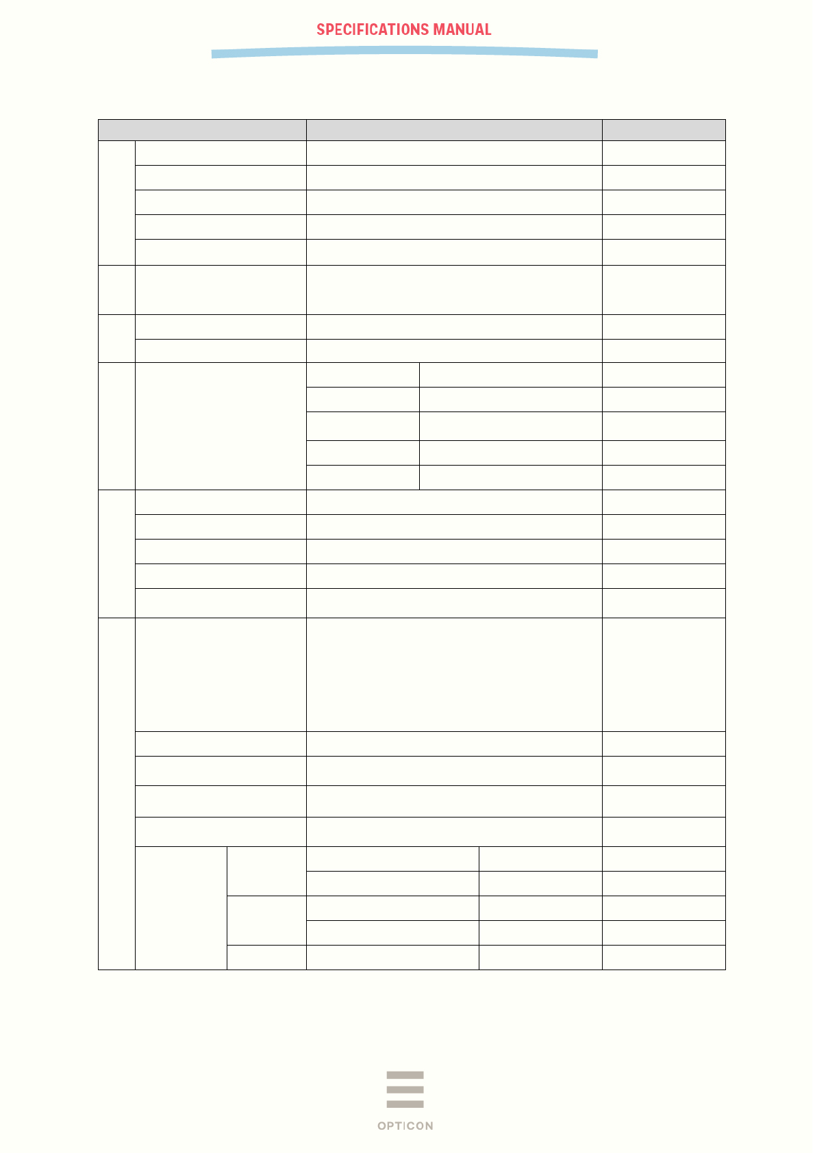
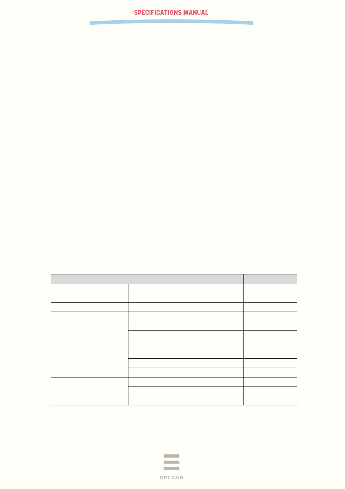
3 Basic Specifications
Item Specification Note
Control Section
CPU 32 bit CISC / 96 MHz
FROM (OS only) 512 Kbyte + 32 Kbyte
SRAM (OS only) 96 Kbyte
FROM (storage) 1 Mbyte For applications
SRAM (storage) 1 Mbyte For applications & file
system
Input
Section
Key type 18 keys: trigger, up, down, CLR, BS, shift and 10
numeric keys
Indic
ator
LED 3 colors (red, green and blue)
Buzzer Loudness and tone adjustable
Interface
Bluetooth
Frequency 2402 ~ 2480 MHz
Specification Bluetooth Ver 4 compliant
Communication
distance
10 m Range depends on
environment
Output level Class 2 Max output 4 dBm
Profile SPP / HID
Optical Section
Scan method WVGA (0.36 million-pixel) CMOS area sensor Frame rate: 60 fps
Light source for illumination 2 red LEDs
Light source for aiming 1 green LED
Effective pixels 0.36 million pixels (H: 752 x V: 480)
View angle
Horizontal: about 40.6°
Vertical: about 26.4°
Supported 1D Symbologies
Symbologies
UPC-A, UPC-A Add-on, UPC-E, UPC-E Add-on,
EAN-13, EAN-13 Add-on, EAN-8, EAN-8 Add-on,
JAN-8, JAN-13, Code 39, Tri-Optic, NW-7,
Industrial 2 of 5, Interleaved 2 of 5, S-Code, IATA,
Code 93, Code 128, MSI/Plessey, UK/Plessey,
TELEPEN, Code 11, Matrix 2 of 5, Chinese Post
Matrix 2 of 5, Korean Postal Authority code,
Intelligent Mail Barcode, POSTNET, JPN
The list is constantly
updated with new
symbologies so this
list may not be
complete.
Minimum resolution Code 39 : 0.1 mm PCS 0.9
Curvature R ≥ 16 mm (10-digit 0.15 mm Codabar)
R ≥ 20 mm (12-digit UPC)
PCS 0.9
Wide bar code 100 mm wide 0.2 mm resolution Code 39 (DOF 115
mm) is readable:
Motion Tolerance
UPC 100% moving at 2m/sec (DOF 80 mm)
is readable:
Depth of Field
Code 39 Resolution 0.127 60 ~ 95
Resolution 0.254 45 ~ 185
Code 128 Resolution 0.508 50 ~ 250
Resolution 0.20 65 ~ 150
UPC Resolution 0.33 45 ~ 175
PX-36
V-1.0
8
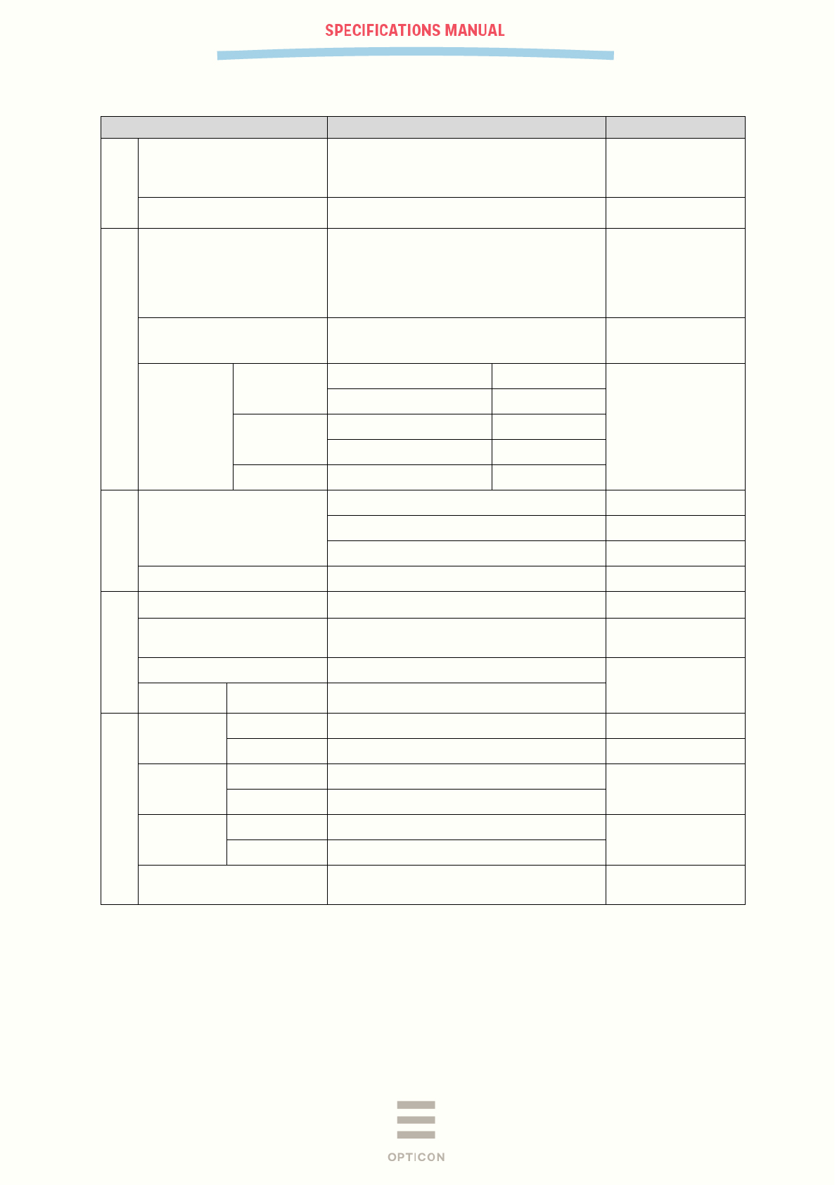
Item Specification Note
GS1/Composite
Symbologies
GS1 DataBar, GS1 DataBar Limited, GS1
DataBar Expanded, Composite GS1 DataBar,
Composite GS1-128, Composite EAN,
Composite UPC
GS1 DataBar: formerly
called “RSS”
Minimum resolution
GS1 DataBar
0.169 mm
Composite Code
0.169 mm
Supported 2D Symbologies
Symbologies
PDF417, MicroPDF417, Codablock F, QR
Code, MicroQR Code, Data Matrix (ECC 0 -
140 / ECC 200), MaxiCode (Modes 2 to 5),
Aztec Code, Aztec Runes, Chinese-sensible
code, PLANET,Netherlands KIX,UK Postal,
Australian Postal
Disable Code 128
when Codablock F is
enabled.
Refer to Chapter 17. for
details
Minimum resolution (mm)
PDF417
0.169 mm
PCS 0.9
QR Code
0.169 mm
DataMatrix
0.212 mm
Depth of field
(mm)
PDF417 Resolution 0.169 55 ~ 105
PCS 0.9
Resolution 0.254 35 ~ 155
QR Code Resolution 0.212 70 ~ 95
Resolution 0.381 35 ~ 165
DataMatrix Resolution 0.254 65 ~ 120
Common
Scan angle
Pitch : ±50°
Skew : ±50°
Tilt : ±180°
Minimum PCS 0.2 or more MRD 12% or more
Power Section
Main battery Lithium-ion 1880 mAh (typ.)
Charge the battery
before initial use
Up-time 20 hours or more
1 scan/10 sec, room
temp, active SPP
connection.
Operating (charging) voltage 6.0V ± 10% Charging with dedicated
cradle.
Current
consumption
Charging Approx 300mA
Environmental Specifications
Temperature Operating 0 ~ 50°C
Storage -20 ~ 60°C
Humidity Operating 20 ~ 85% No condensing
No frost
Storage 20 ~ 85%
Ambient light
immunity
Fluorescent 10,000 lx or less UPC, optical axis angle 75°,
distance 90 mm. See figure
1 below for details
Sunlight 100,000 lx or less
Drop Drop the scanner 12 times (6 faces x 2) from
the height of 150 cm onto a concrete floor
PX-36
V-1.0
9
Item Specification Note
Regulatory Compliance
LED safety IEC 62471-1:2006 Exempt Group
Peak Wavelength
624 nm
Product safety EN60950-1:2005
IEC60950-1:2006
EMC
EN 55022:2010
EN 301 489-1 V1.9.2
EN 301 489-17 V2.1.1
EN 300 328 V1.8.1
FCC Part 15 Subpart C, Subpart B ClassB
For residential,
commercial and light-
industrial environments
Other Bluetooth logo certification
Immunity
Test
ESD No distruction Air discharge (direct): ±15 kV Conditions:
IEC61000-4-2
compliant
No malfunction Contact discharge (direct / indirect): ±6 kV
Air discharge (direct): ±8 kV
Physical
Features
Dimensions 44 × 25 × 140 (WDH mm)
Weight Approx. 115 g Excluding battery
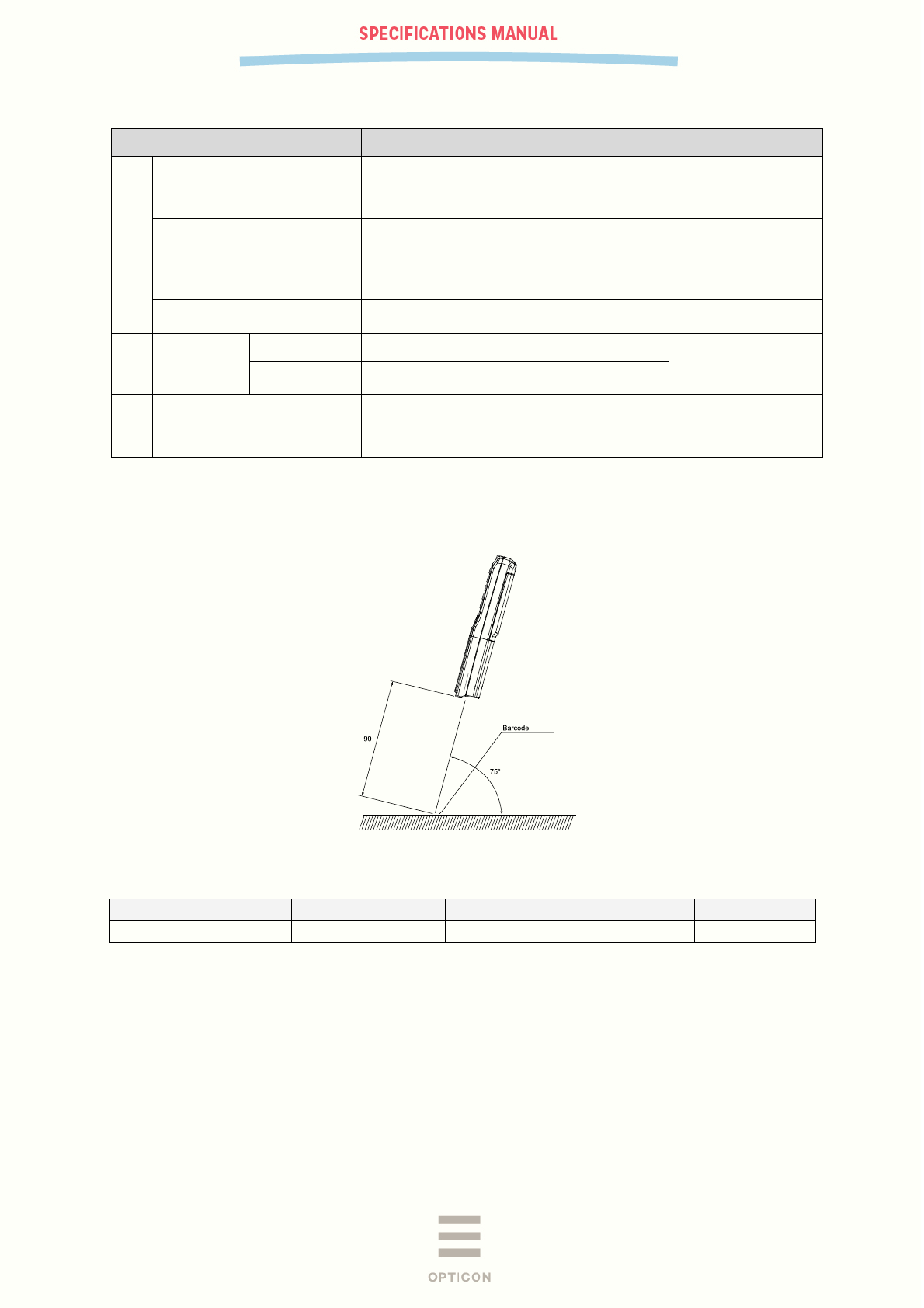
3.1 Ambient Light Immunity conditions
Ambient Light Immunity is measured using the following conditions:
Figure 1: Ambient Light Immunity
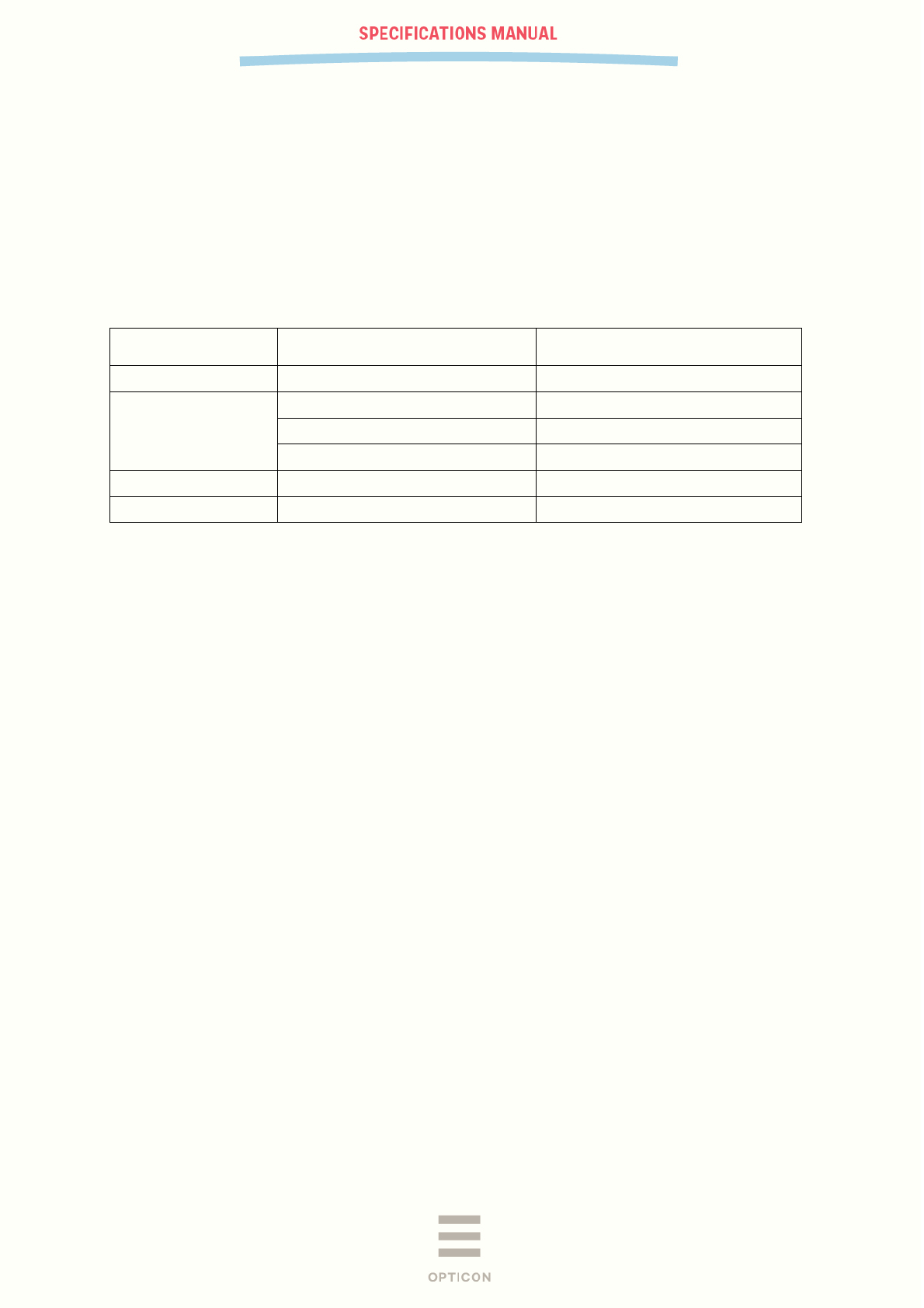
Barcode Label:
Resolution Symbology PCS Size (mm) No. of Digits
0.330 mm (13mil) 12-digit UPC 0.9 31.5 × 25.0 12
Angles : α = 0°, β = +15°, γ = 0°
Curvature : R = ∞
Note: α, β and γ respectively represent pitch, skew and tilt. Please see chapter 7.4 for details on how
these values are defined.
PX-36
V-1.0
10
4 Electrical Specifications
4.1 Main Battery
The main battery is a lithium-ion secondary battery.
Nominal capacity: 1880 mAh
Battery charging time: Approximately 7 hours
Battery type: NP120, without leads
4.2 Battery Operating Time and Charging Time (TBD)
Parameter Specifications Notes
Backup battery 3 mAh manganese dioxide battery
Current consumption 1 mA or less* Standby
100 mA or less* Bluetooth and Backlight on
400 mA or less* When scanning
Usable time 10 hours or more 1 scan/5s
Data hold time 72 hours or more After main battery discharged
*With nominal battery voltage (3.7V)
PX-36
V-1.0
11
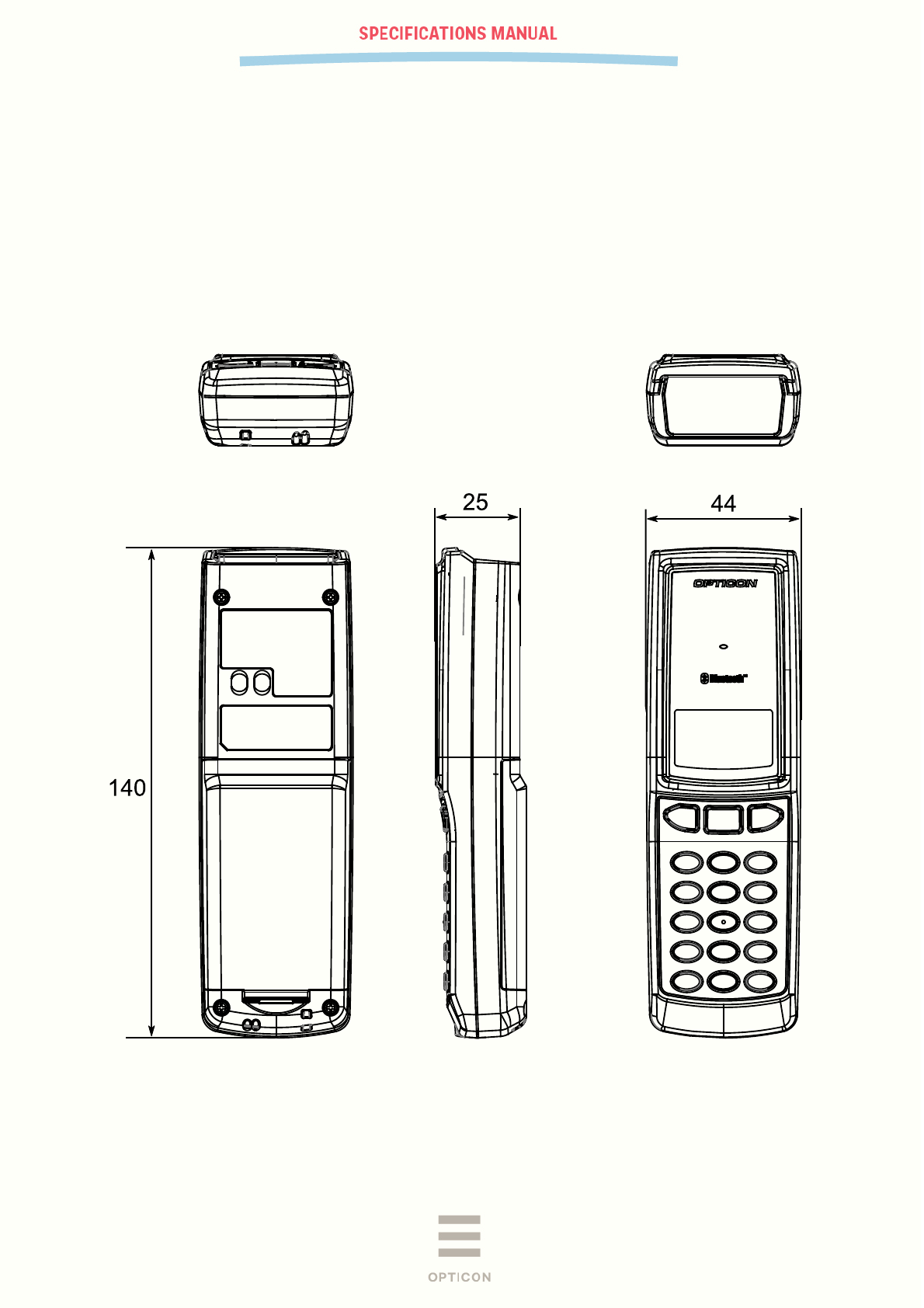
5 Mechanical
5.1 Dimensions
W 44.0 mm x D 25.0 mm x H 140.0 mm
5.2 Weight
115 g (max.), excluding the lithium-ion battery
5.3 Color
Black
Figure 2: Mechanical drawing
PX-36
V-1.0
12
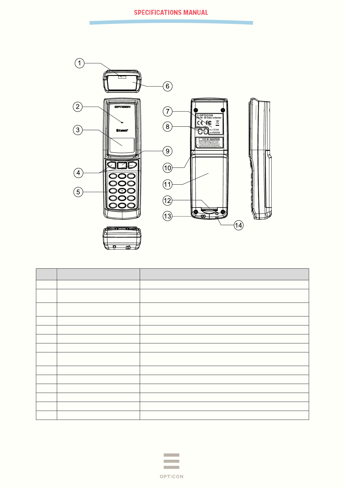
5.4 Detailed view
Figure 3: Detailed view
No. Items Descriptions
1 IrDA Infra-red transceiver Infrared port for communication with the cradle.
2 LED Indicator
Indicator of operating status, such as bar code reading,
Bluetooth and warnings
3 LCD
Monochrome Liquid Crystal display to show the decoded data,
operational processes and so on.
4 Up / Down keys Up/down keys used to move between menu items.
5 Operation keys (10) Keys used for numerical input, backspace, Clear and Shift
6 Scanning window Window for the CMOS camera
7 Product Label Place for serial label with regulatory logo’s
8 Charging contacts
Terminals used to charge the lithium-ion battery in the PX-36
when it is placed into a dedicated cradle
9 Trigger key This key triggers the 2D barcode reader.
10 FCC warning label This label shows the FCC regulatory information
11 Battery cover Lid to keep the battery inside the PX-36
12 Battery cover lock Used to lock / open the battery cover
13 Buzzer hole Opening in the enclosure to let the sound of the buzzer out.
14 Hand strap hole Hole for attaching a hand strap
PX-36
V-1.0
13
6 Interface Specifications
6.1 Bluetooth
Frequency 2402 ~ 2480 MHz
Specification Bluetooth 2.1 compliant
Communication distance 10 m
Output level Class 2 (max 4 dBm)
Implemented profile SPP / HID Classic Bluetooth
GAP based Low Energy mode
Communication configuration 1 to 1
Operating mode in communication Master / Slave mode
Security mode Authentication supported
Encryption Encryption supported
6.2 IrDA
6.2.1 Specifications
The PX-36 features an IrDA module that is compliant to the ver1.2 low power SIR specification.
6.2.2 Transmission Speed
Default transmission speed is set at 115.2 kbps. However, you can easily change the transmission
rate to 57.6 kbps, 38.4 kbps, 19.2 kbps, 9600 bps, 4800 bps, or 2400 bps.
7 Optical Specifications
7.1 Basic Optical Specifications
Item Characteristics
Scan method CMOS area sensor (white / black) -
Effective pixels (Column) × (Row) 752 × 480 dots
Image capture speed (*1) Frame rate 60 fps
Focal distance Distance from the front edge of scanner 104 mm
View angle Horizontal Approx. 40.6°
Vertical Approx. 26.4°
Light source for illumination
(LED × 2)
Red LED -
Peak wavelength 617 nm
Directivity angle: 2Φ 1/2 (*2) 60°
Maximum radiation output (*3) 15000 mcd
Light source for aiming
(LED × 1)
Green LED -
Peak wavelength 528 nm
Maximum radiation output (*4) 18700 mcd
*1 The fastest seed of image capture
*2 The LED intensity is > 50% in this area, compared to the intensity at the center of the
optical axis. This is the reference value from the LED datasheet.
*3, *4 Reference value based on the datasheet (25°C, IF = 140 mA ).
PX-36
V-1.0
14
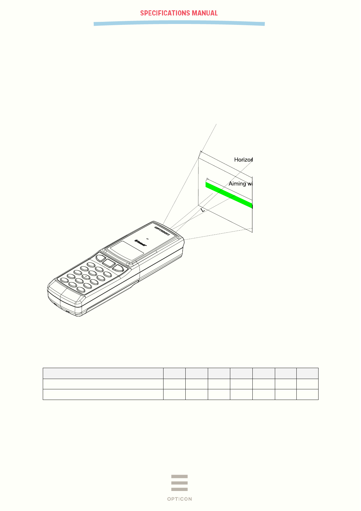
7.2 Aiming Pattern
The aiming pattern is used for the following purposes:
1. Light source to indicate the appropriate reading range.
2. Light source for auto trigger operation.
The specifications for the aiming pattern are as follows:
・ The optical axis of the field of view and the center of the aiming pattern coincide at a distance of
L=65±20 mm from the front edge of the scanner.
・ The width of the aiming pattern is 80%±10% of the width of the field of view at a distance of
L=65mm.
Figure 4: Aiming pattern
7.3 Imaging Range
L: Distance from the front edge of scanner [mm] 40 60 80 100 120 140
H: Horizontal imaging range [mm] 66 82 97 111 125 136
V: Vertical imaging range [mm] 42 52 62 72 82 93
All values have an accuracy of ±5%.

PX-36
V-1.0
15
7.4 Barcode reading/decoding specifications
7.4.1 Conditions
When the aiming patter is positioned over the centre of a barcode label, the scanner is able to read it.
The conditions for the following specifications are as follows unless otherwise specified in each
section.
Temperature and humidity Room temperature, room humidity
Ambient light 100 ~ 200 lx
Angles Pitch: α = 0°, Skew: β = 15°, Tilt: γ = 0°
Curvature R = ∞
PCS (1D and 2D) 0.9 or higher
Scanning Test 1 read in 0.5 sec or less. Accept the performance with 70% or more
success rate for 10 readings.
Bar code test sample
(1D and 2D)
Refer to section 7.4.2 for details.
<Bar code labels used>
1D codes: Opticon test sheet
2D codes (incl. GS1 Databar, and stacked codes): Labels printed by a dedicated barcode printer
PX-36
V-1.0
16
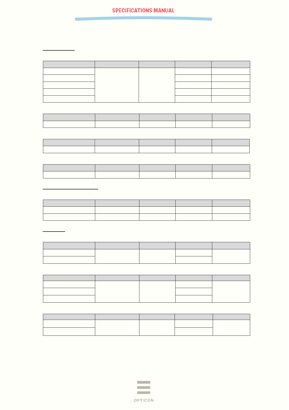
7.4.2 Bar Code Test Sample
1D Bar Codes
<Code 39>
Resolution Symbology PCS Size (mm) No. of Digits
0.1 mm
Code 39 0.9
9 × 10 4
0.127 mm 32 × 10 15
0.20 mm 100 × 10 31
0.254 mm 32.5 × 12 7
0.508 mm 36 × 25 4
<Code 128>
Resolution Symbology PCS Size (mm) No. of Digits
0.20 mm Code 128 0.9 42 × 10 16
<UPC>
Resolution Symbology PCS Size (mm) No. of Digits
0.330 mm 12-digit UPC 0.9/0.2 31.5 × 25.0 12
<Codabar>
Resolution Symbology PCS Size (mm) No. of Digits
0.150 mm Codabar (NW-7) 0.9 20 × 10 10
GS1 Databar/Composite
<GS1-limited>
Resolution Symbology PCS Size (mm) No. of Digits
0.169 mm Limited 0.9 12 × 1.5 14
0.169 mm Limited-Composite 0.9 12 × 3.0 26
2D Codes
<PDF417>
Resolution Error Correction PCS Size (mm) No. of Character
0.169 mm Level-3 0.9 23 × 10 58
0.254 mm 35 × 15
<QR Code: Model-2>
Resolution
Error Correction
PCS
Size (mm)
No. of Character
0.169 mm
M 0.9
5 × 5
44
0.212 mm 6 × 6
0.381 mm 11 × 11
<Data Matrix>
Resolution
Model
PCS
Size (mm)
No. of Character
0.212 mm ECC200 0.9 5 × 5 40
0.254 mm 6 × 6
Note: The size of the barcode does not include the quiet zones.
PX-36
V-1.0
17
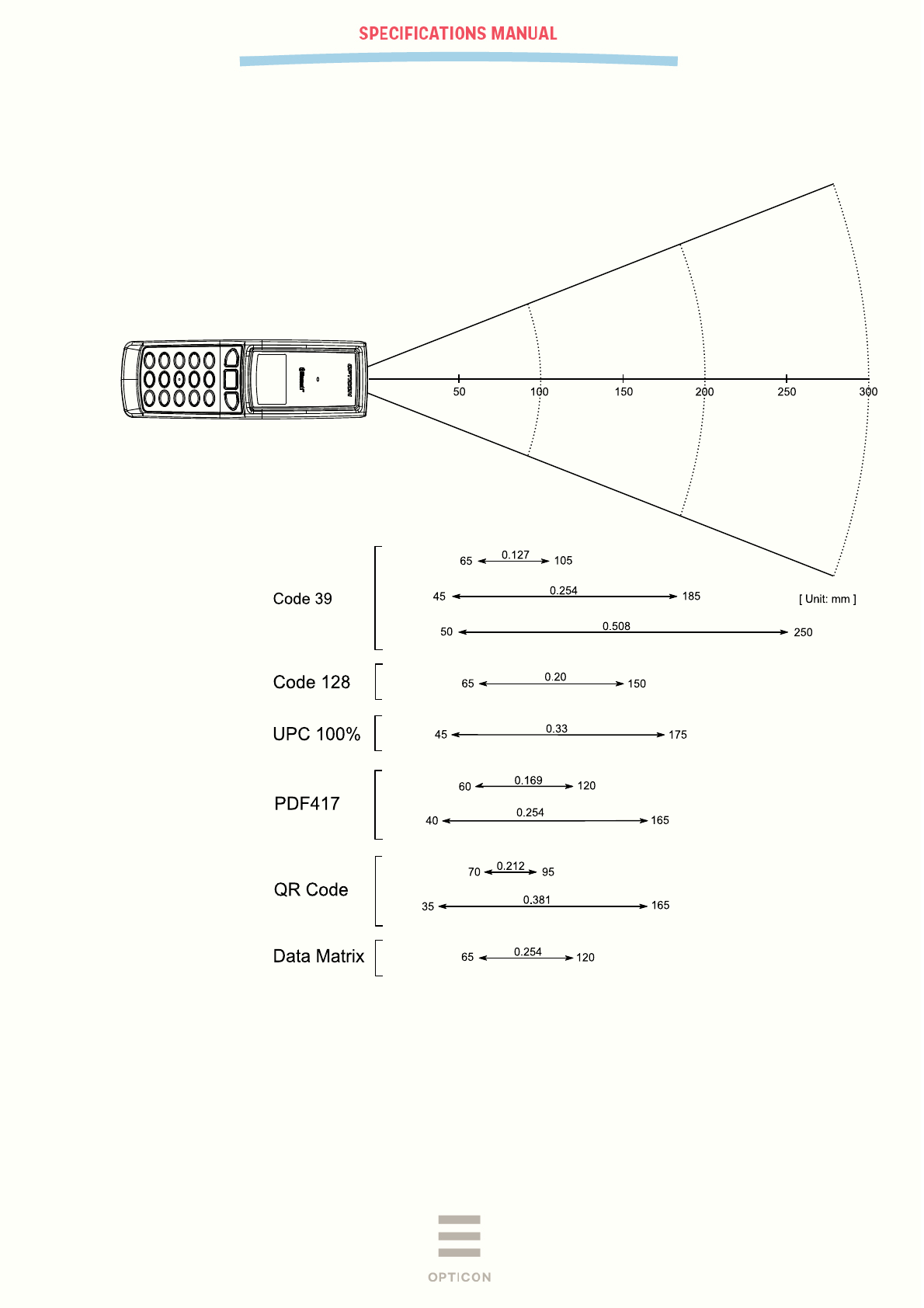
7.4.3 Scan Area and Depth of Field
The depth of field is measured from the edge of the data collector. The scanning range is within the
circular arc centered on the scan origin.
Figure 5: Scan Area and Depth of Field
PX-36
V-1.0
18
7.4.4 Printed Contrast Signal (PCS)
0.2 or higher
<Conditions>
MRD
12% and higher (70% or higher reflectivity of space and quiet zone)
Distance
105 mm from the front edge of the scanner
Bar code
UPC (resolution 0.33 mm, PCS 0.2) specified in Section 8.1.
MRD = Minimum reflectance of white space - Maximum reflectance of black bar
𝑃𝐶𝑆 =𝑅𝑒𝑓𝑙𝑒𝑐𝑡𝑎𝑛𝑐𝑒 𝑜𝑓 𝑤ℎ𝑖𝑡𝑒 𝑠𝑝𝑎𝑐𝑒 −𝑅𝑒𝑓𝑙𝑒𝑐𝑡𝑎𝑛𝑐𝑒 𝑜𝑓 𝑏𝑙𝑎𝑐𝑘 𝑏𝑎𝑟
𝑅𝑒𝑓𝑒𝑐𝑡𝑎𝑛𝑐𝑒 𝑜𝑓 𝑤ℎ𝑖𝑡𝑒 𝑠𝑝𝑎𝑐𝑒
* Be sure to keep the optical window clean without dirt or scratches or it may have a bad effect on the reading
characteristics.
7.4.5 Minimum Resolution
1D bar code
0.1 mm (Code 39 specified in Section 7.4.2)
GS1 Databar
0.169 mm (GS1 Databar Limited specified in Section 7.4.2)
Stacked code
0.169 mm (PDF417, GS1 Databar Limited Composite specified in Section 7.4.2)
2D code
0.169 mm (QR Code specified in Section 7.4.2)
0.212 mm (Data Matrix specified in Section 7.4.2)
<Conditions>
Bar code
Above codes specified in Section 7.4.2
Distance
75 mm from the front edge of the scanner
Angle
α = 0°, β = + 15°, γ = 0°
Curvature
R = ∞
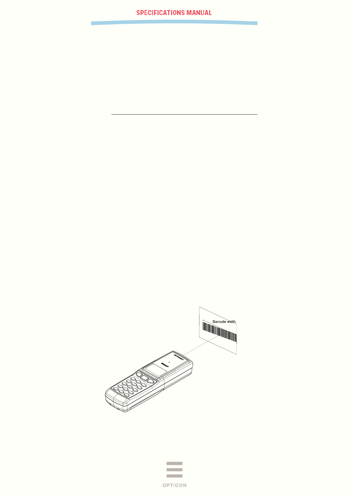
7.4.6 Max. Width Barcode
Code 39 with width of 100 mm and resolution of 0.2 mm can be read
<Conditions>
Bar Code
Code 39 (resolution 0.20 mm, PCS 0.9) specified in Section 7.4.2
Distance
135 mm from the front edge of the scanner
Angle
α = 0°, β = +15°, γ = 0°
Curvature
R = ∞
Figure 6: Barcode width
PX-36
V-1.0
19
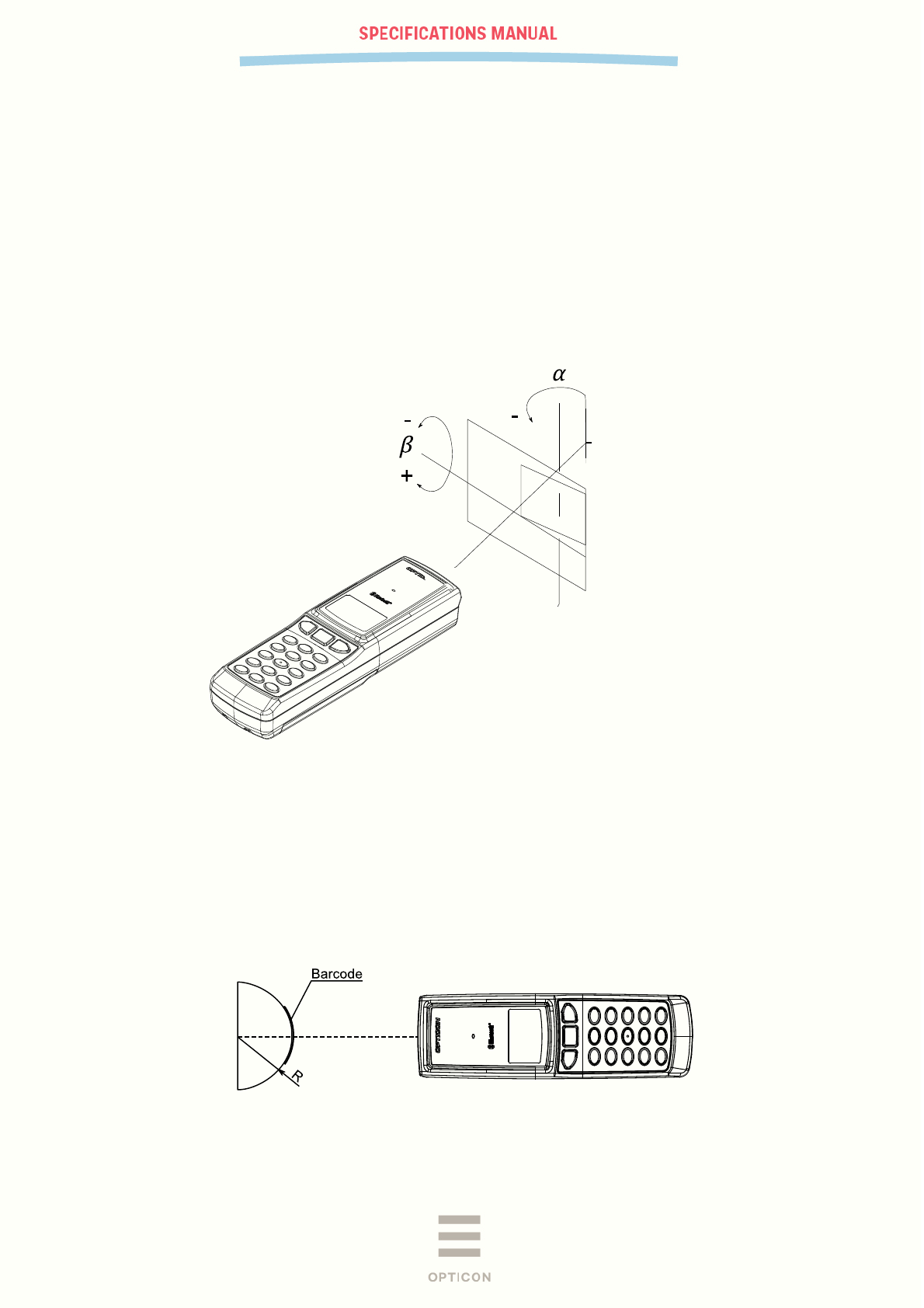
7.4.7 Pitch, Skew and Tilt
Pitch
α = ±50°
Skew
β = ±50°
Tilt
γ = ±180°
<Conditions>
Bar code
UPC (resolution 0.33 mm) specified in Chapter 7.4.2
Distance
105 mm from the front edge of the scanner
Curvature
R = ∞
Angle
Pitch
β = +15°, γ = 0°
Skew, Dead zone
α = 0°, γ = 0°
Tilt
α = 0°, β = +15°
Figure 7: Pitch, Skew and Tilt
7.4.8 Curvature
0.33 mm 12-digit UPC
R ≥ 20 mm
0.15 mm 10-digit Codabar (NW-7)
R ≥ 16 mm
<Conditions>
Bar code
UPC (0.33 mm) and Codabar (0.15 mm) specified in Section 8.1.
Distance
85 mm from the front edge of the scanner
Angle
α = 0°, β = +15°, γ = 0°
Figure 8: Curvature
* The reading characteristics may deteriorate due to specular reflection of the LED illumination when reflectivity is
high.
PX-36
V-1.0
20
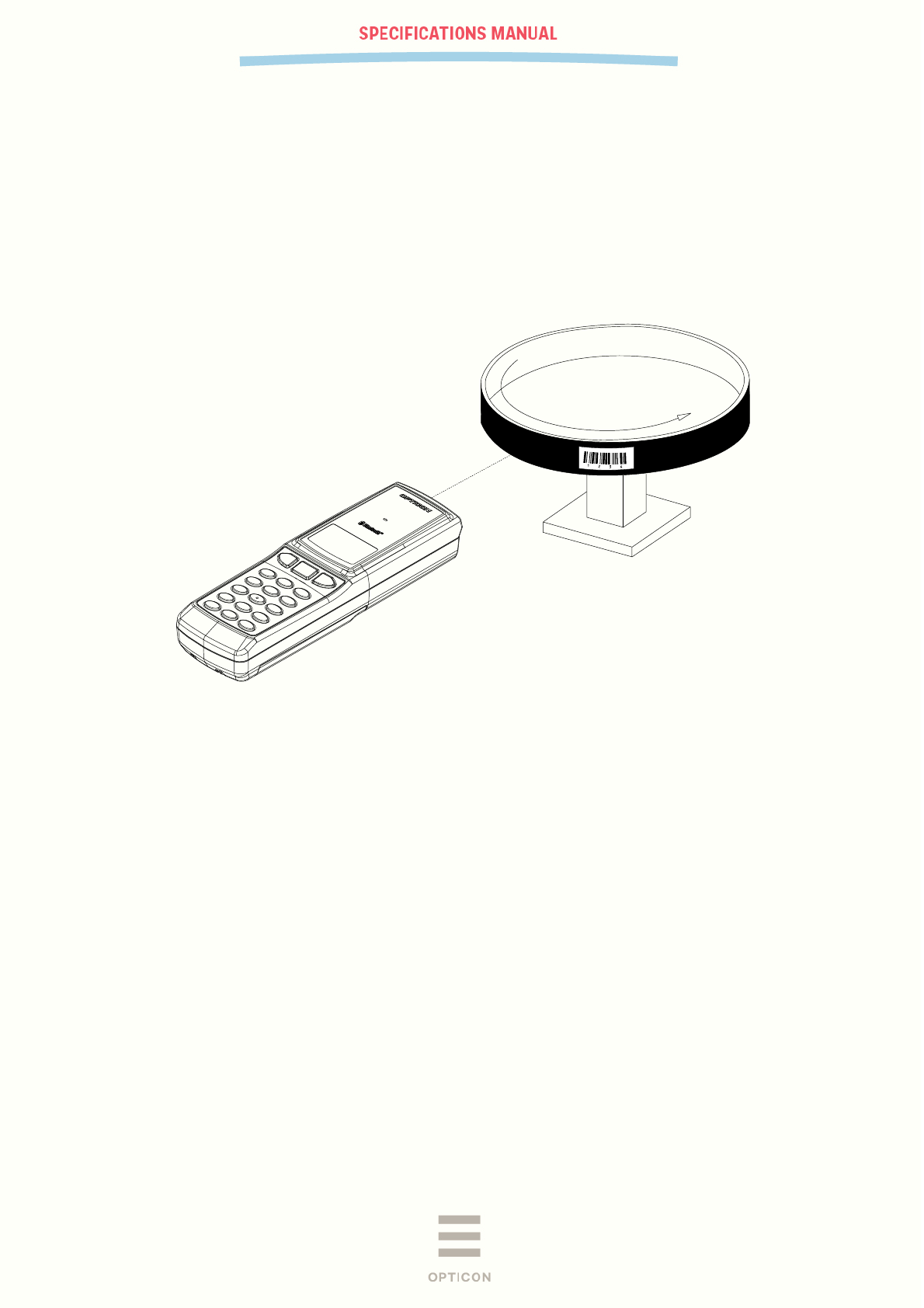
7.4.9 Motion Tolerance
UPC bar codes moving at 2m/s can be read for 100%.
<Conditions>
Temperature / Humidity
Room temperature / room humidity
Ambient light
500 ~ 1000 lx
Distance
105 mm from the front edge of the scanner
PCS
0.9 or higher
Bar code
Refer to Section 7.4.2
Figure 9: Motion tolerance
* The reading characteristics may deteriorate due to specular reflection of the LED illumination when reflectivity is
high.

PX-36
V-1.0
21
8 Environmental Specifications
8.1 Temperature
Scanning performance is guaranteed when the range of ambient temperature around the scanner is
the following values:
Operating temperature
0 ~ 50
°C
Storage temperature
-20 ~ 60°C
8.2 Humidity
Scanning performance is guaranteed when the range of ambient humidity around the scanner is the
following values:
Operating humidity
20 ~ 85% RH (no condensation, no frost)
Storage humidity
20 ~ 85% RH (no condensation, no frost)
9.3. Ambient Light Immunity
Scanning performance is guaranteed when the range of illumination on a bar code surface is between
zero and the following values:
Incandescent light
10,000 lx
Fluorescent light
10,000 lx
Sunlight
100,000 lx
<Conditions>
Bar code
UPC (resolution 0.33 mm) specified in Section 7.4.2.
Distance
105 mm from the front edge of the camera module
Angle
α = 0°, β =
+
15°, γ = 0°
Curvature
R = ∞
* Be sure that direct light or specular reflection from the light source does not enter the light receiving
section of the scanner.
PX-36
V-1.0
22
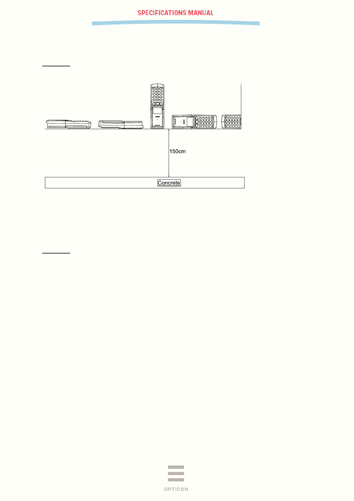
8.3 Drop Impact Strength (without packaging)
There shall be no sign of malfunction after the following drop test.
Drop test: Drop the scanner 12 times in total (2 times at the 6 positions as indicated) from a height of
150 cm onto a concrete floor.
Figure 10: Drop test
8.4 Drop Impact Strength (in individual packaging)
There shall be no sign of malfunction after the following drop test.
Drop test: Drop an individually packaged scanner 10 times in total, at any of 1 corner, 3 edges, and 6
faces, from a height of 150 cm onto a concrete floor.
8.5 Electrostatic Discharge (ESD) Immunity
Contact discharge
±6 kV max (direct or indirect discharge, no malfunction)
Aerial discharge
±8 kV max (no malfunction)
±15 kV max (no destruction)
Measurement environment
Testing method compliant with IEC-61000-4-2.
Discharge resistance
330 Ω
Charging capacitor
150 pF

PX-36
V-1.0
23
Federal Communications Commission Notices
This product complies with Part 15 of the FCC Rules. Operation is subject to the following two
conditions:
(1) this device may not cause harmful interference, and
(2) this device must accept any interference received, including interference that may cause undesired
operation.
Harmful Interference Notice
This product has been tested and complies with the specifications for a Class B digital device,
pursuant to Part 15 of the FCC Rules. These limits are designed to provide reasonable protection
against harmful interference in a residential installation. This equipment generates, uses, and can
radiate radio frequency energy and, if not installed and used according to the instructions, may cause
harmful interference to radio communications. However, there is no guarantee that interference will
not occur in a particular installation. If this equipment does cause harmful interference to radio or
television reception, which is found by turning the equipment off and on, the user is encouraged to try
to correct the interference by one or more of the following measures:
• Reorient or relocate the receiving antenna
• Increase the separation between the equipment or devices
• Connect the equipment to an outlet other than the receiver's
• Consult a dealer or an experienced radio/TV technician for assistance
Changes or modifications to this equipment that have not been approved by Ruckus Wireless may
void the user's authority to operate this equipment.
RF Exposure Information
This product complies with FCC RF radiation exposure limits set forth an uncontrolled environment.
9 Regulatory Compliance
9.1 LED Safety
IEC 62471:2006 Exempt Group
9.2 Product Safety
EN60950-1:2006
IEC60950-1:2005
9.3 EMC
R&TTE Directive
・EN 55022:2010
・EN 301 489-1 V1.9.2
・EN 301 489-17 V2.1.1
・EN 300 328 V1.9.1
FCC Part 15 Subpart B Class B
PX-36
V-1.0
24
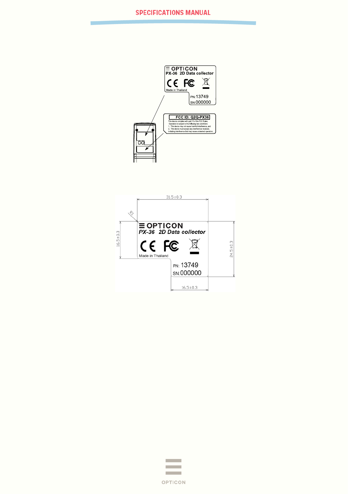
10 Labeling
The PX-36 has two labels, a serial number label and an FCC warning label.
Figure 11: PX-36 product labels
10.1 Serial Number label
Detailed drawing:
Figure 12: Serial number label
Label dimension:
31.5mm x 24.5mm. Tolerance ± 0.3mm
Label material:
Consist of base + laminate protection against wear.
Base : PP film, Pantone Cool gray 1, thickness 80µm, backing with glue.
Laminate : PET film, clear, thickness 25µm, backing with glue.
Product number (PN:)
13749
Serial number (SN:)
Data: 6 digits numeric.
Serial number starts with 000001. Increment with 1 for each label. So, 000001, 000002, 000003, etc.
No double serial number may exist.
During production, the serial number is also programmed inside the PX-36’s non volatile
memory. API functions are available to retrieve that number.
Colors:
Pantone Black
PX-36
V-1.0
25
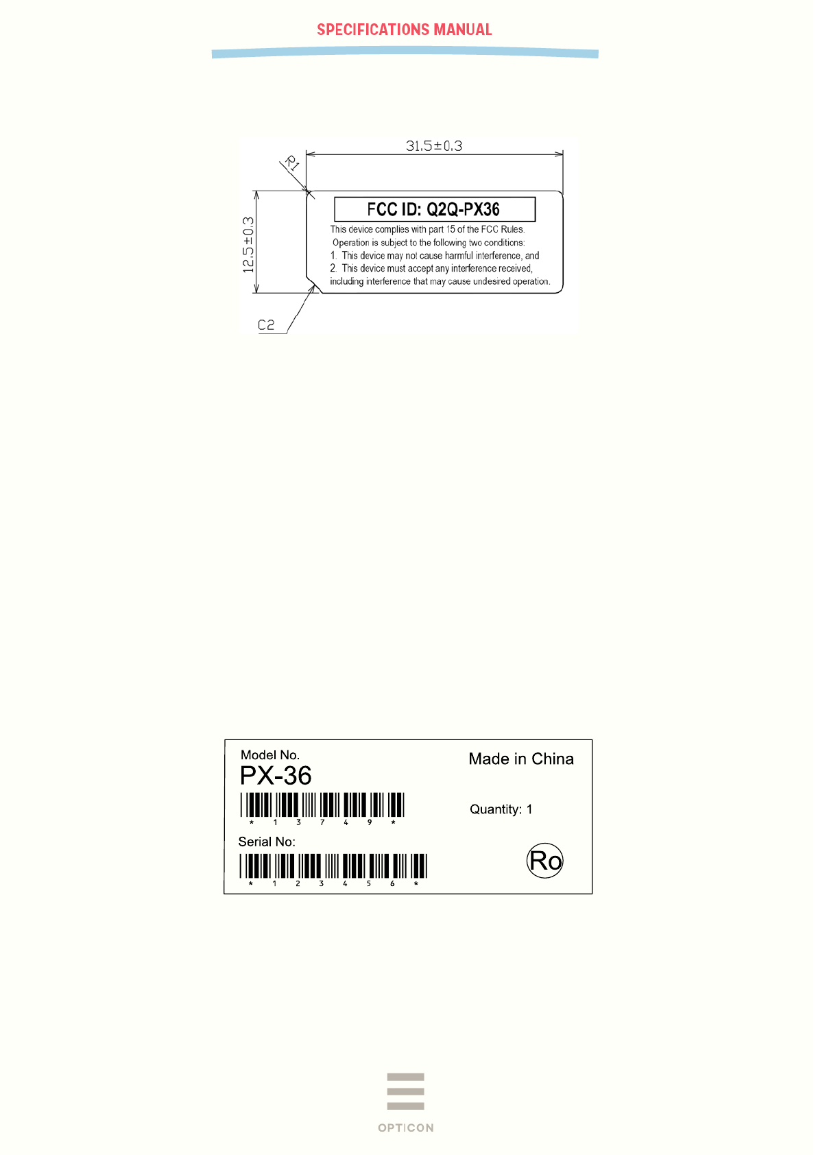
10.2 FCC Warning Label
Detailed drawing:
Figure 13: FCC warning label
Label dimension:
31.5mm x 12.5mm. Tolerance ± 0.3mm
Label material:
Consist of base + laminate protection against wear.
Base : PP film, Pantone Cool gray 1, thickness 80µm, backing with glue.
Laminate : PET film, clear, thickness 25µm, backing with glue.
Colors:
Pantone Black
10.3 White box label
Size is 70mm x 25mm with a tolerance of ± 2 mm
Example labels: Avery 3421 or similar.
Label material: Paper, white, with permanent adhesive backing.
Article number: Standard code 39 + human readable text
Bar code data: 13749
Serial number: Standard code 39 + human readable text
Bar code data: The serial number. This should match that of the PX-36
Figure 14: White box label
PX-36
V-1.0
26
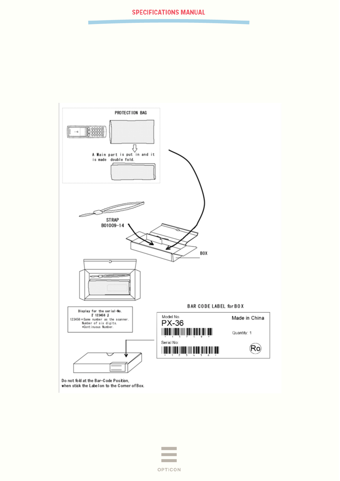
11 Packaging Specifications
11.1 Individual Packaging Specification (TBD)
Put the PX-36 in a protective foam bag and place it in an individual packing box, then place
the accessories into the box. Close the box and affix a label to the side of the box. Size of the
package after assembly: 164 (W) x 64 (D) x 40 (H) mm
Figure 15: Individual packing
PX-36
V-1.0
27
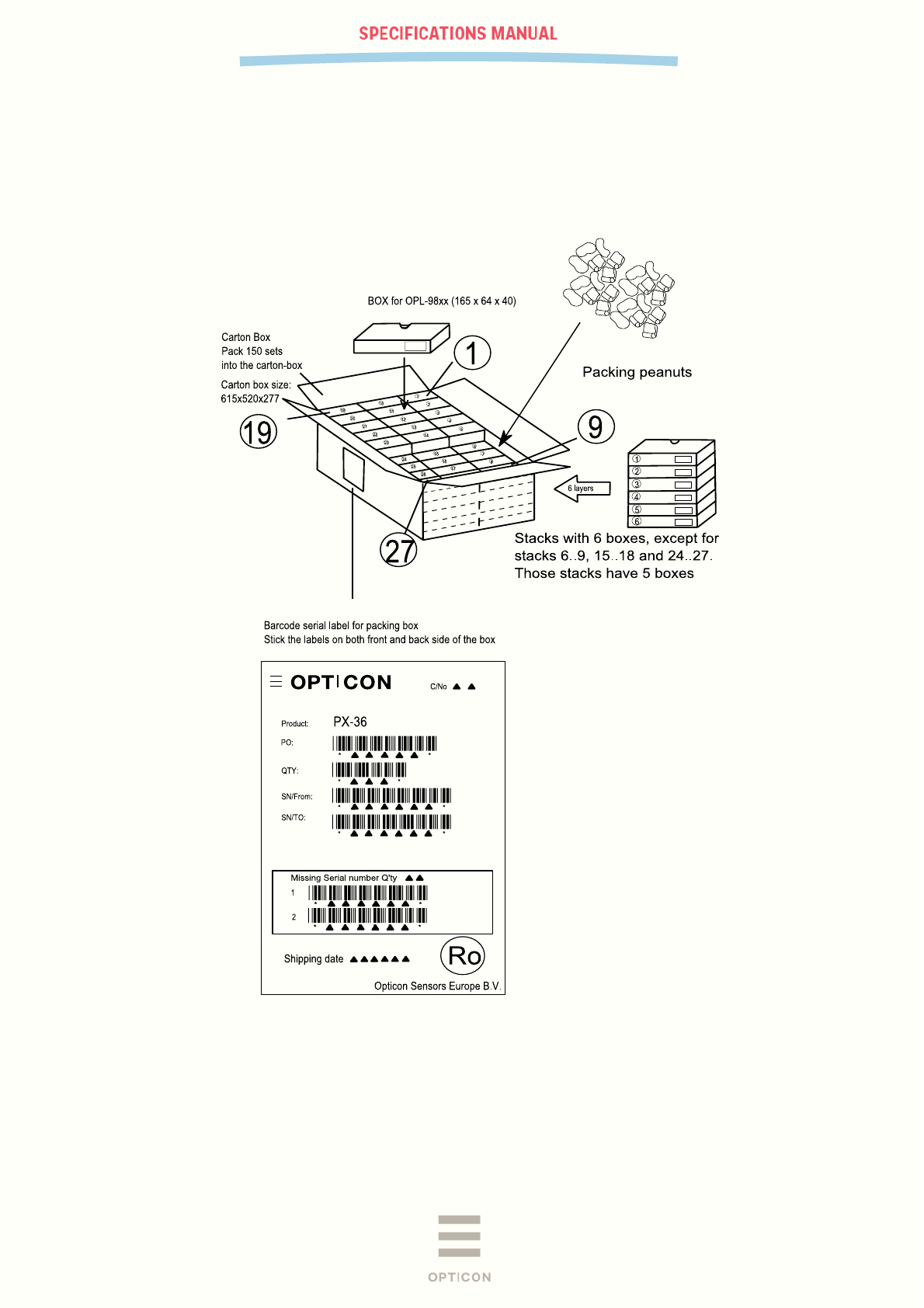
11.3 Collective Packaging Specification
Put 150 individually packaged data collectors in a collective packing box. The box
can hold 162 boxes, so there will be some empty space in the shipping box. That
should be filled by packing peanuts.
Dimensions: 615 mm (W) by 520 mm (D) by 277 mm (H).
Figure 16: Shipment packing
Note: The “RO” mark labeled on the package tray or package box guarantees
that the applicable product has passed our test of RoHS restrictions compliance
(the restriction of the use of certain hazardous substances in electrical and
electronic equipment, 2002/95 EC). However, this document does not have any
legal weight in the European Union.
PX-36
V-1.0
28
12 Safety precautions
Handle this product carefully. Do not deliberately subject it to any of the following.
12.1 Shock
Do not throw or drop the data collector.
Do not drop or put heavy items on this product.
12.2 Temperature Conditions
Do not use the data collector at temperatures outside the specified range.
Do not use near heat sources such as radiators, heat registers, stoves, or other
types of devices that produce heat.
Do not use in areas exposed to direct sunlight for long periods of time.
12.3 Foreign Materials
Limit the use of the data collector near water or other liquids, as well as in
extremely high humidity.
Do not immerse the data collector in liquids.
Do not use in extremely dusty environments.
Do not subject the data collector to chemicals.
Do not insert foreign substances into the device.
12.4 Other
Do not attempt to disassemble, modify or update this device.
Do not use near microwaves, medical devices, or RF-emitting devices.
The data collector may be damaged by high voltage discharges.