Option OMO6092 Nyos LGA CDMA Module User Manual TempConfidential ver01
Option NV Nyos LGA CDMA Module TempConfidential ver01
UserManual.wiki
>
Option
>
OMO6092 User Manual
TempConfidential_User manual ver01
Navigation menu
Upload a User Manual
Namespaces
Wiki Guide
HTML
PDF
Info
Views
User Manual
Discussion / Help
Navigation
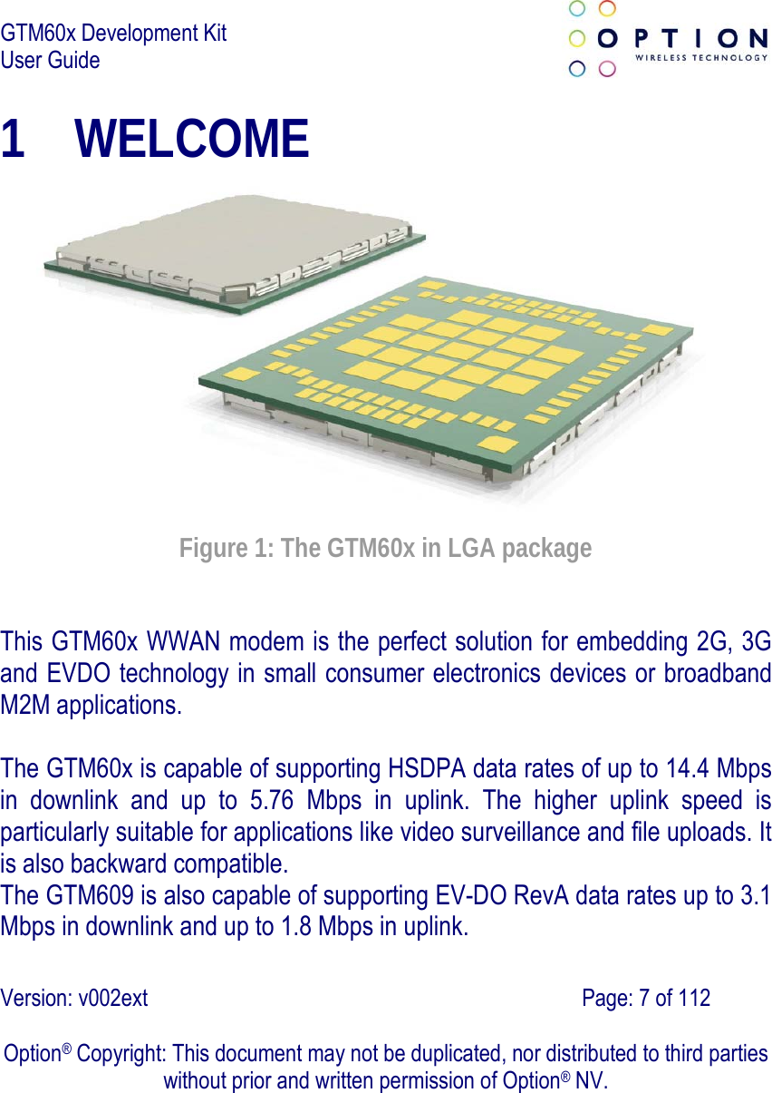
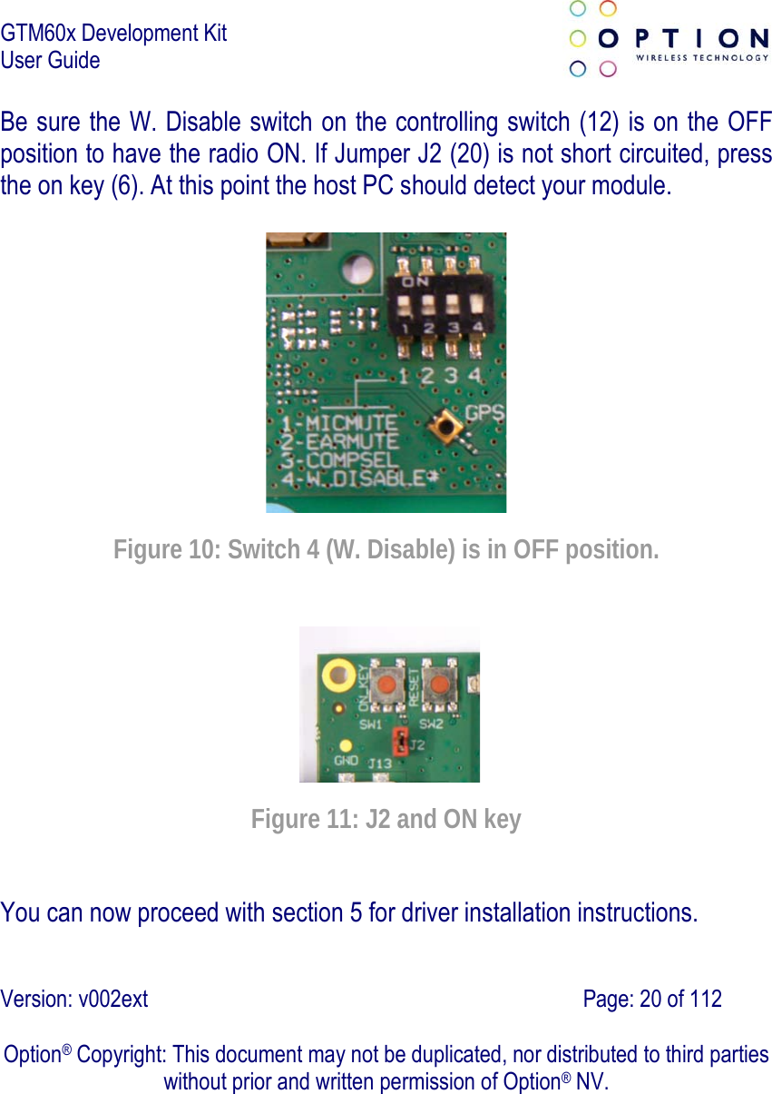
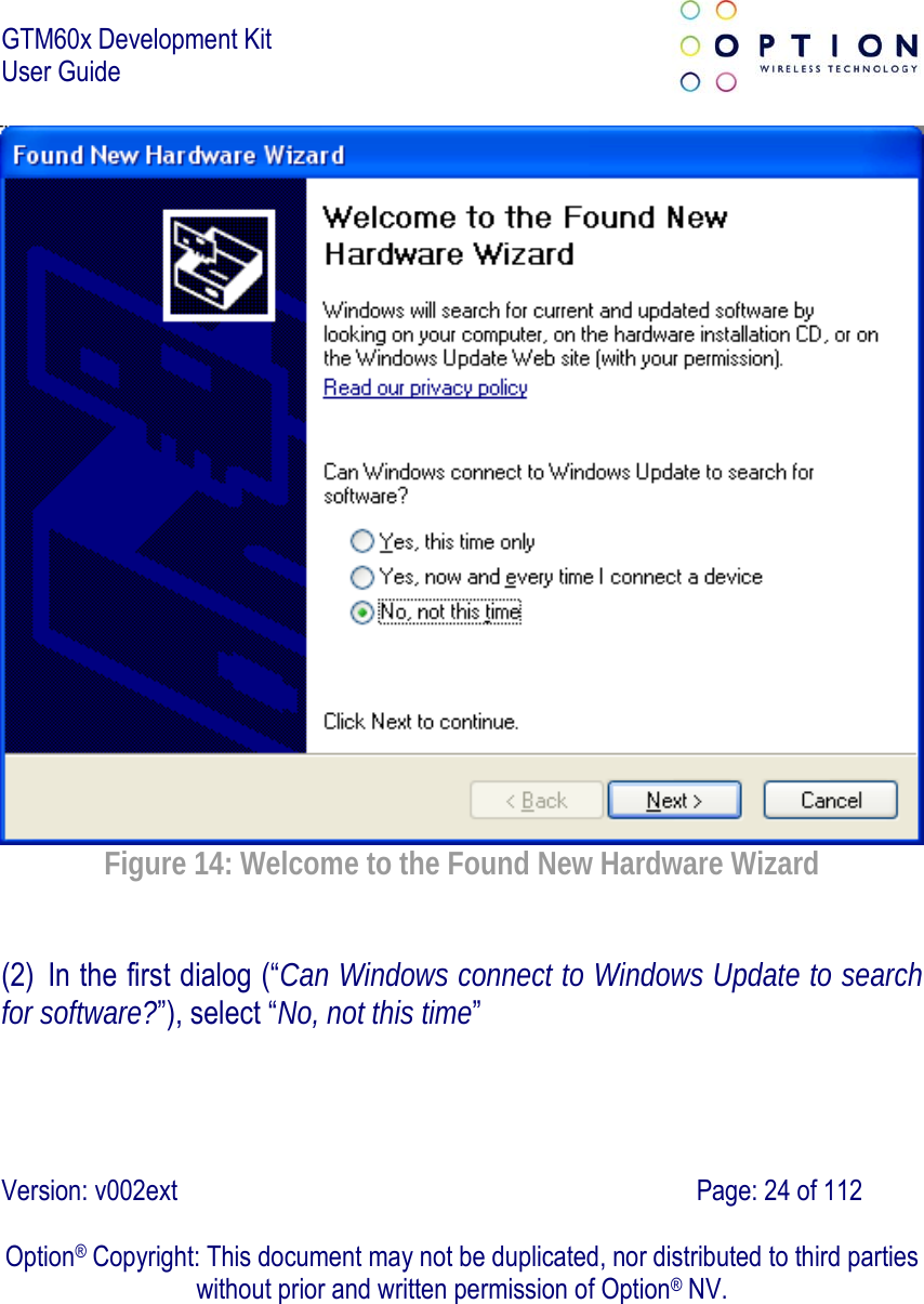
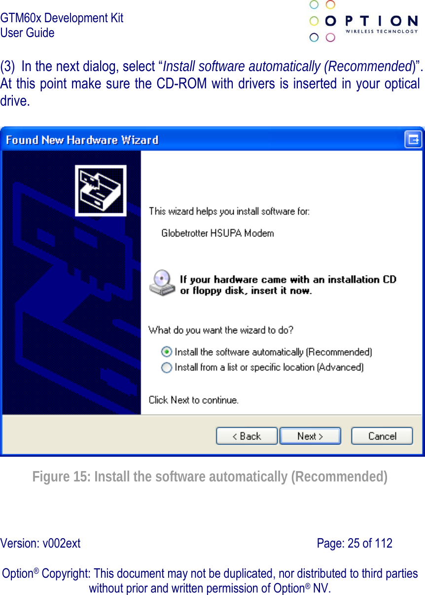
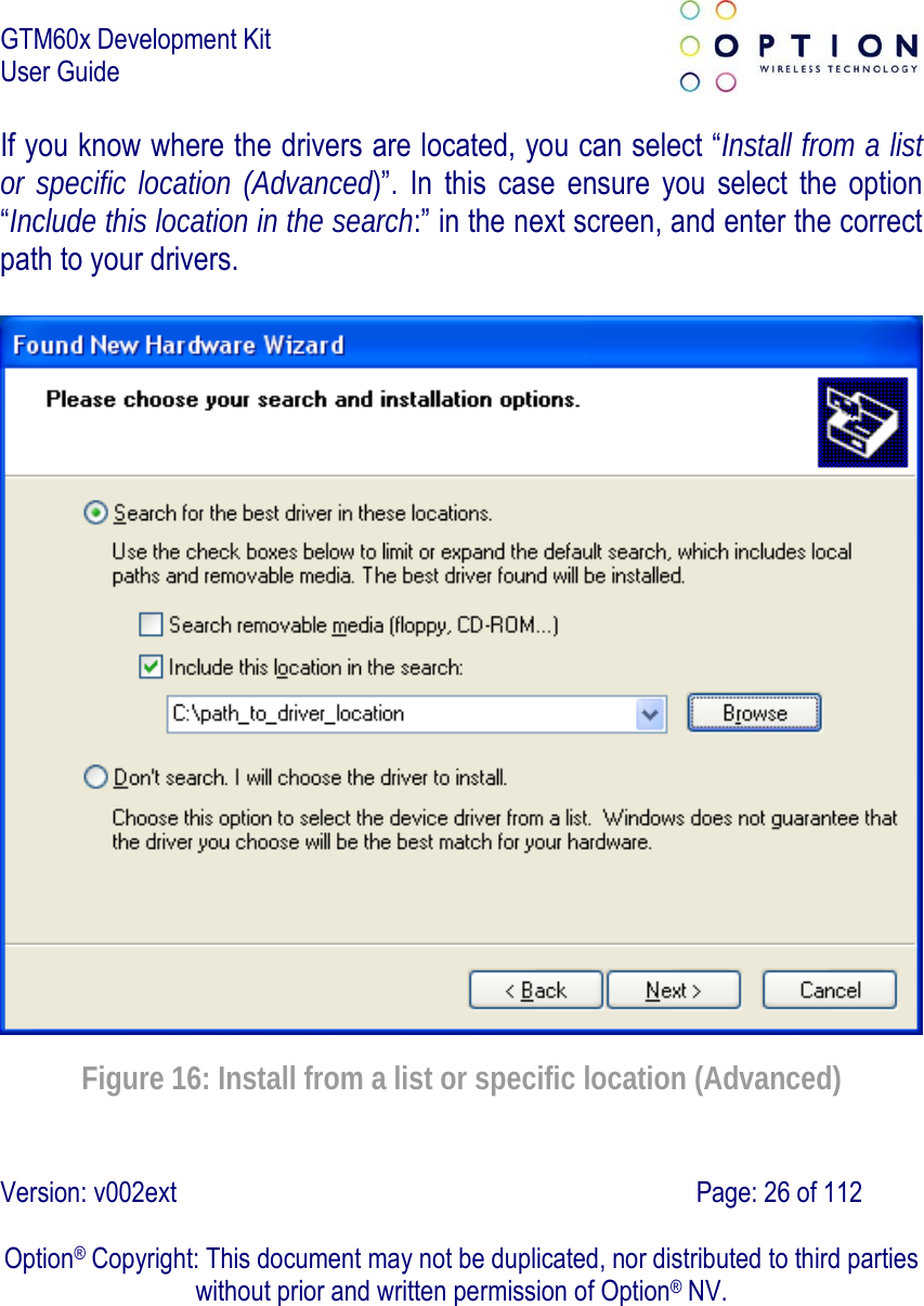
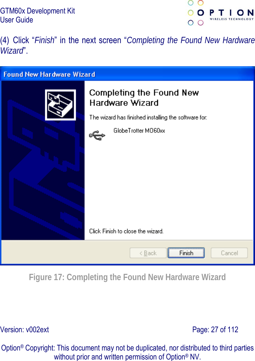
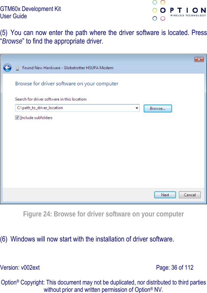
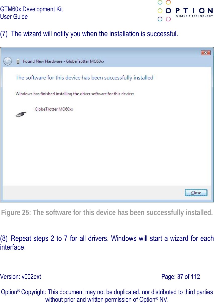
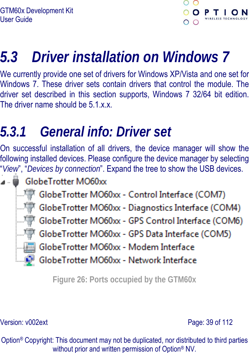
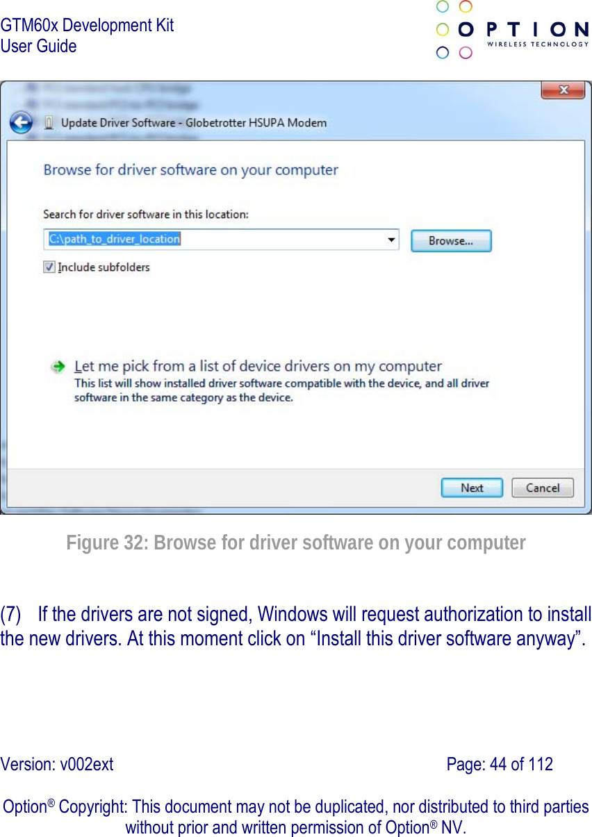
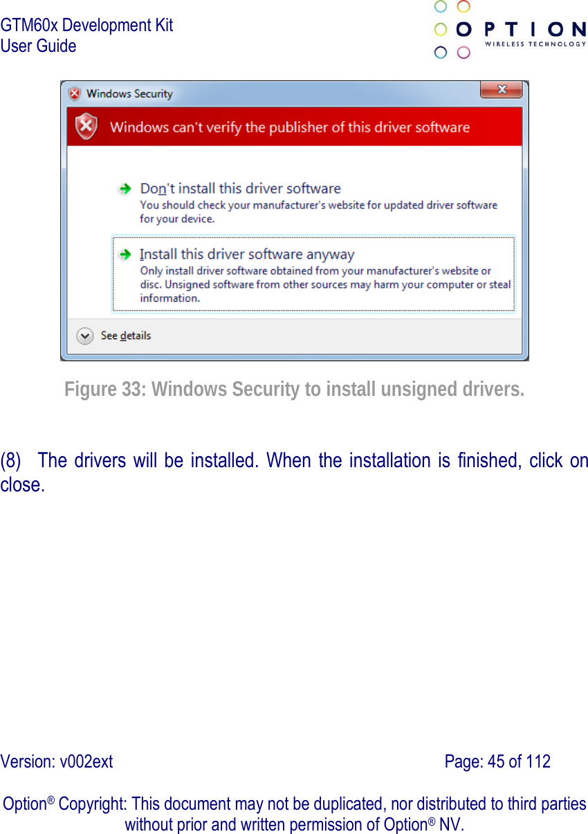
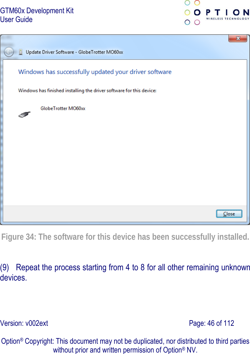
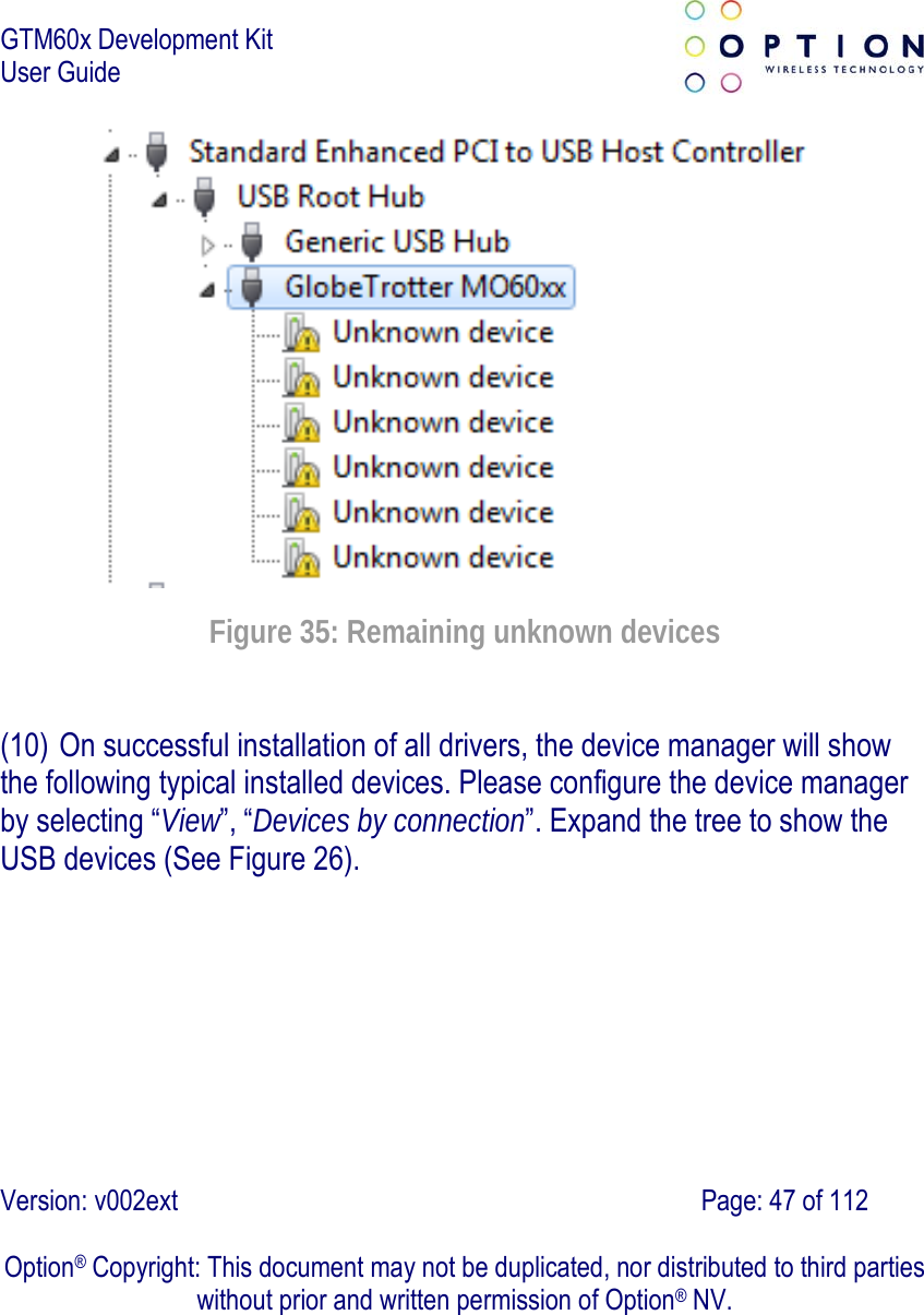
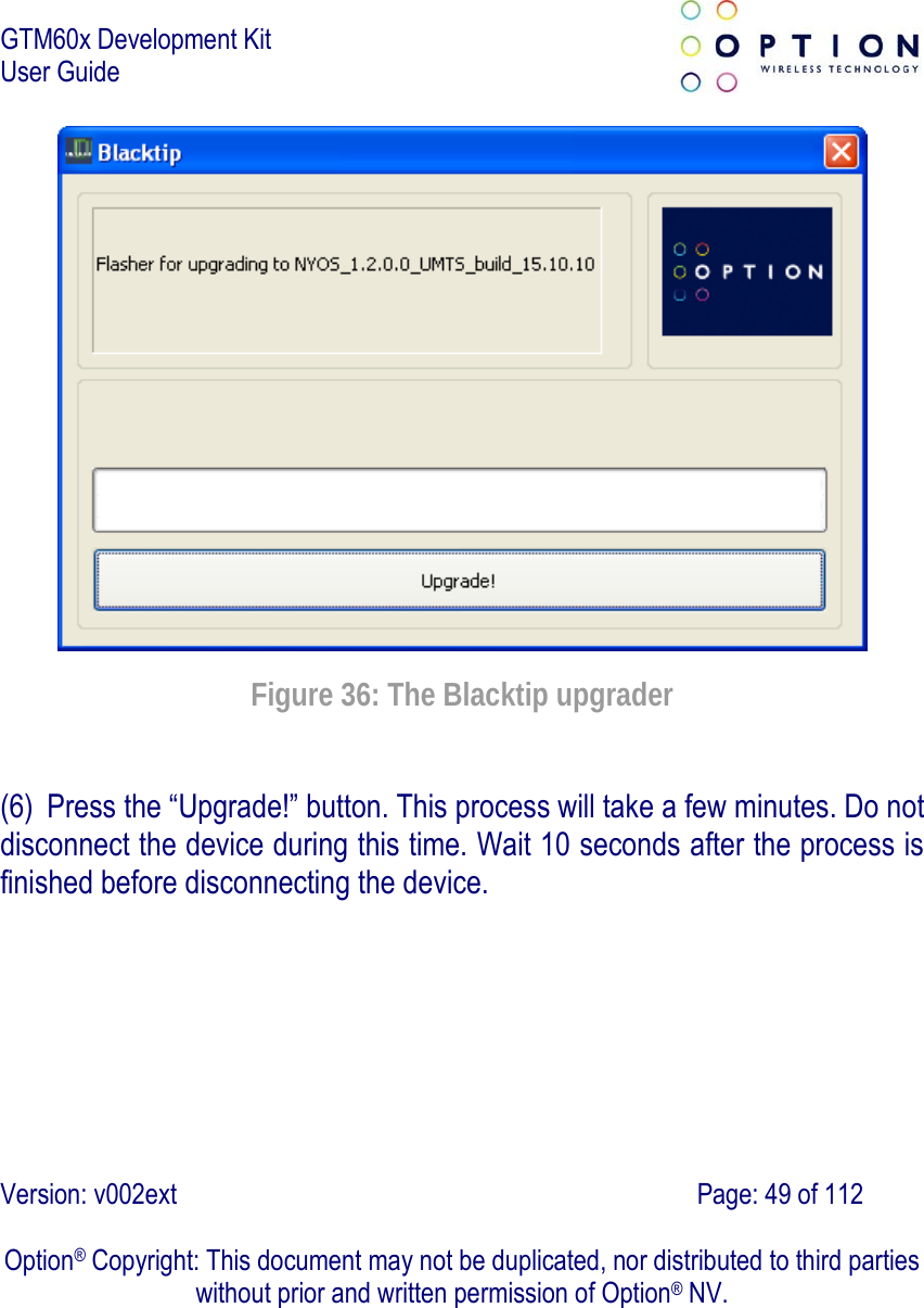
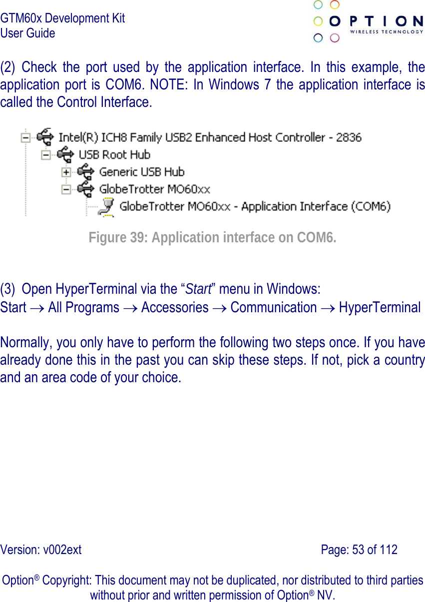
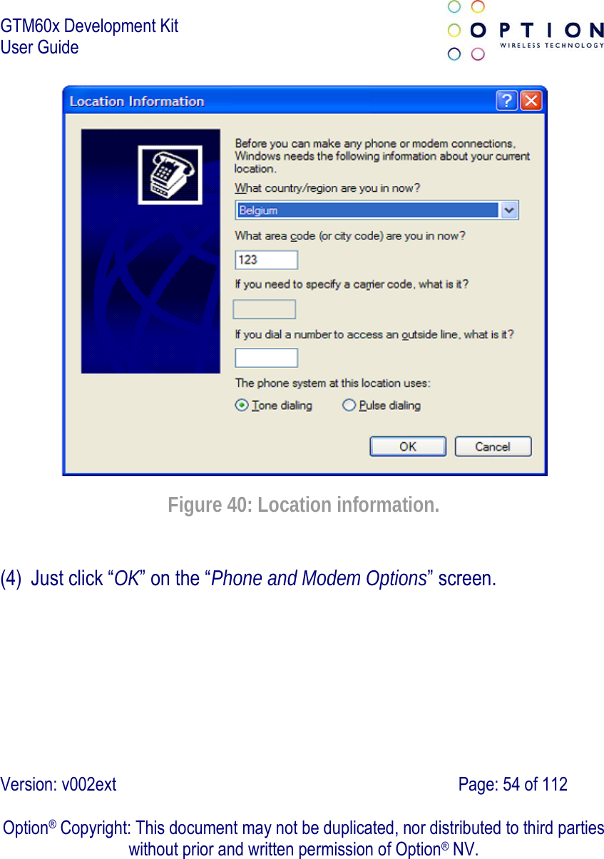
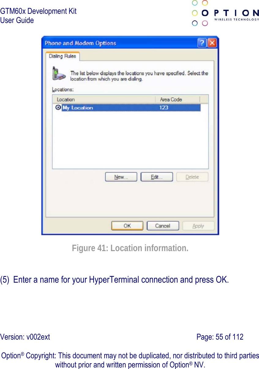
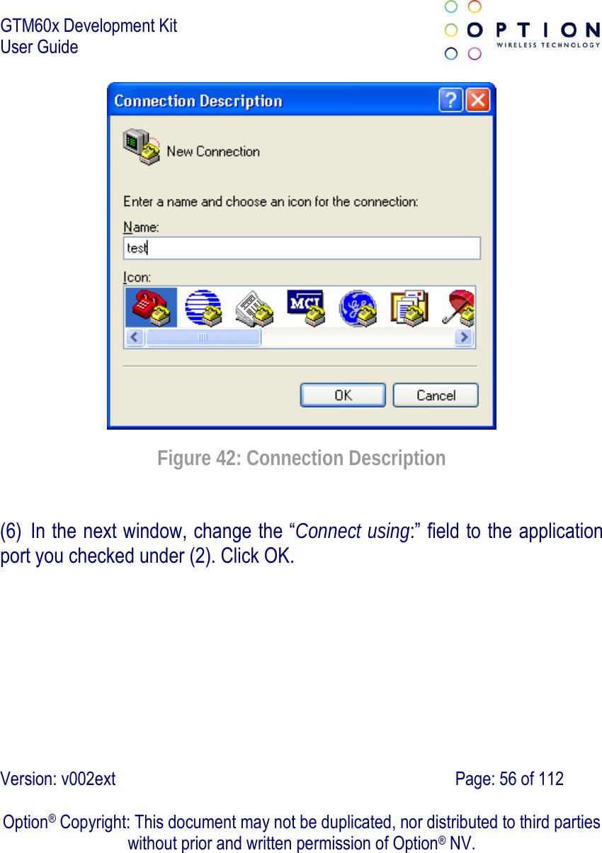
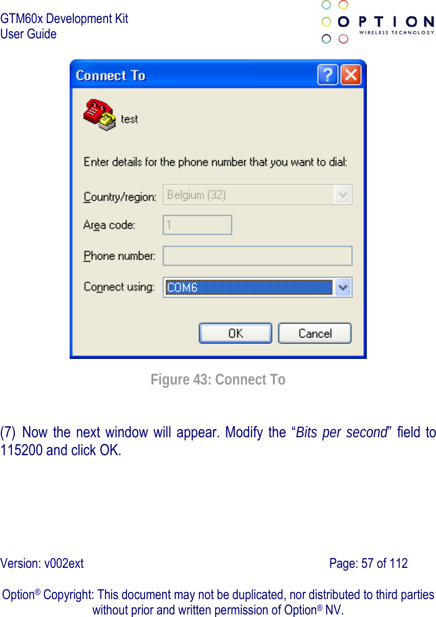
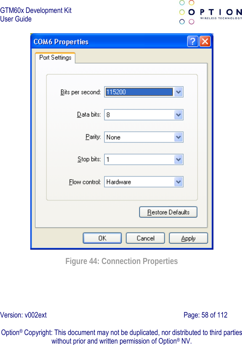
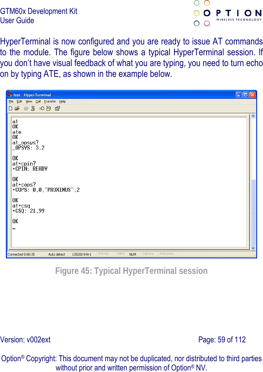
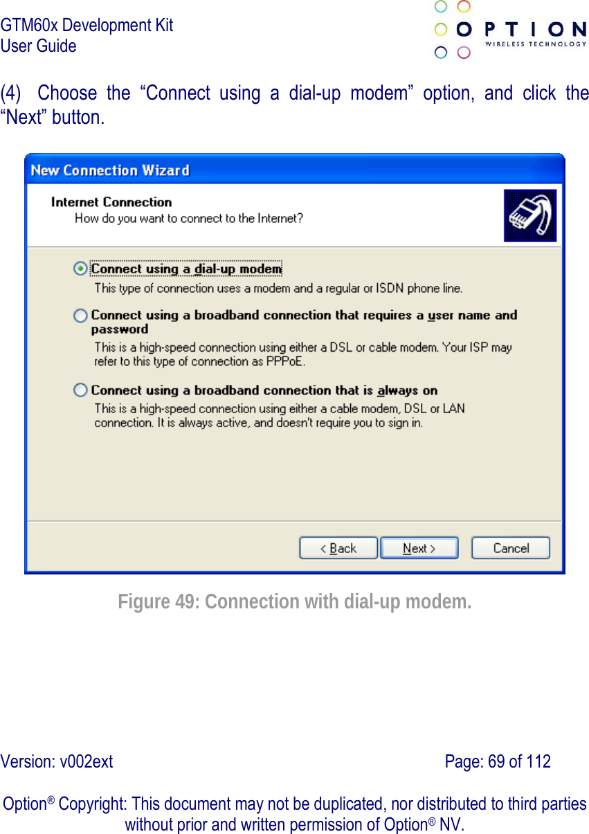
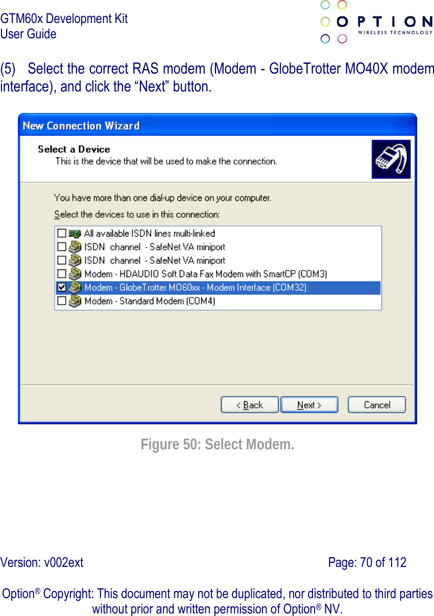
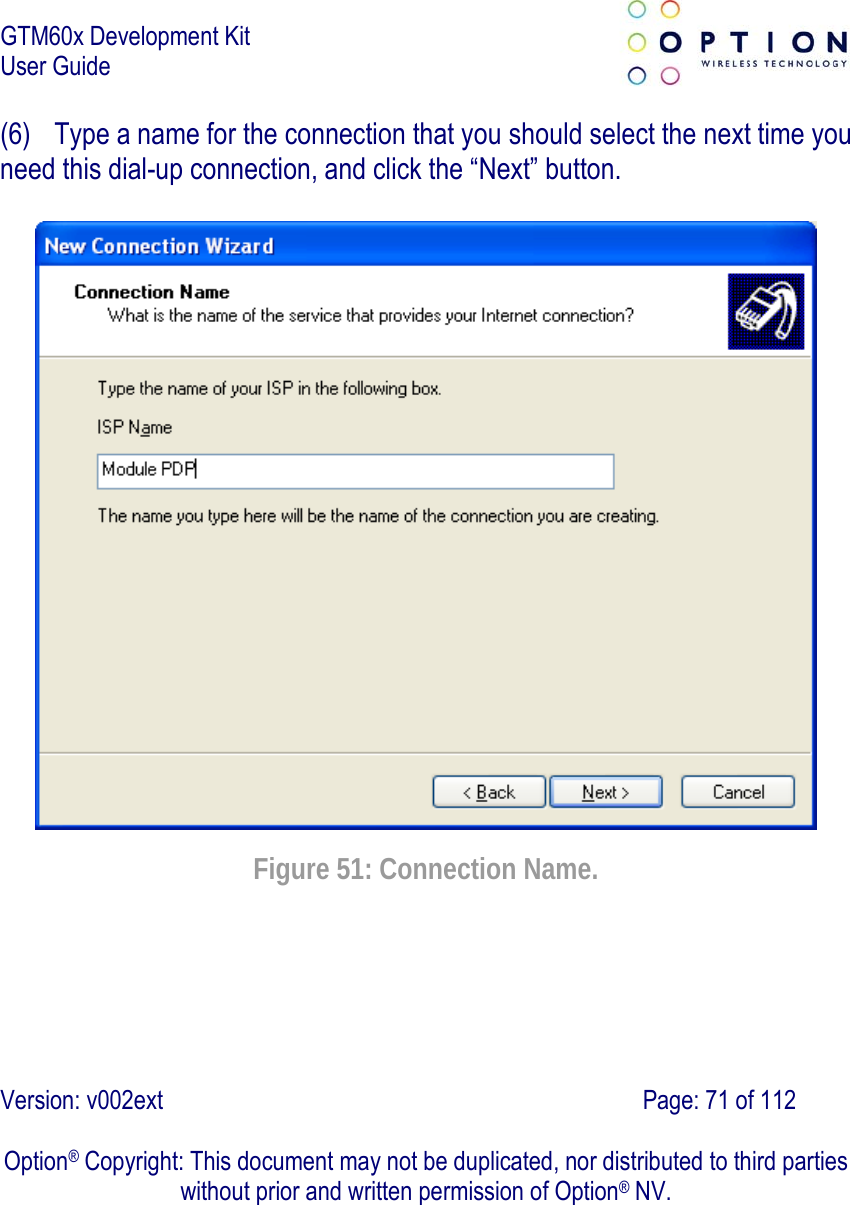
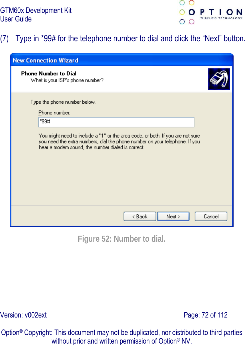
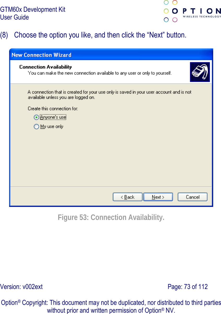
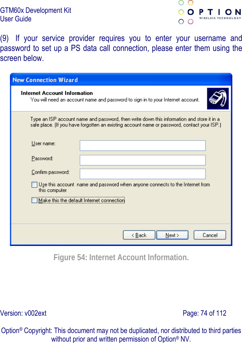
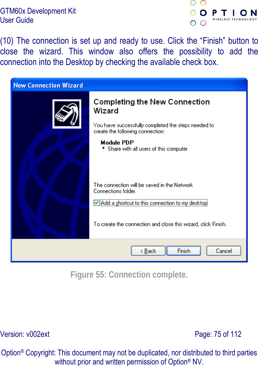
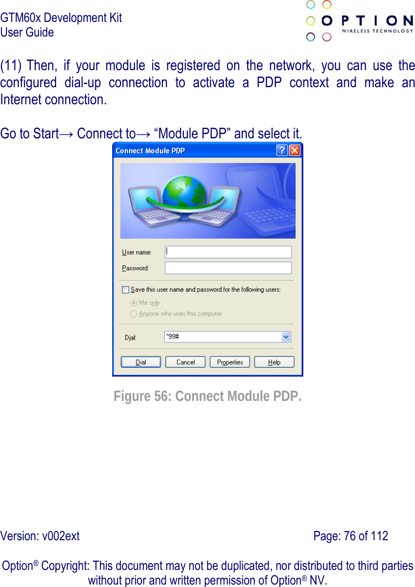
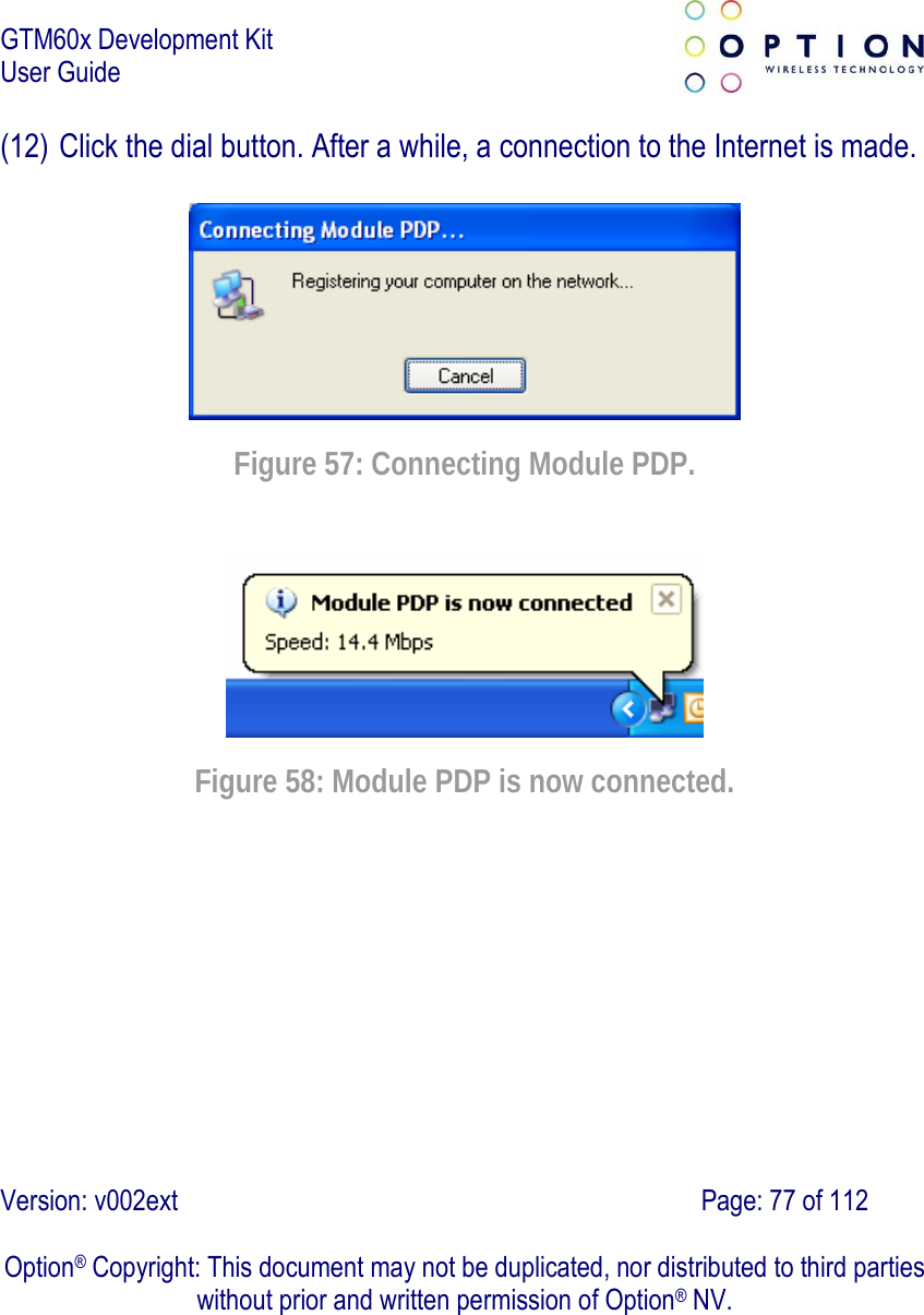
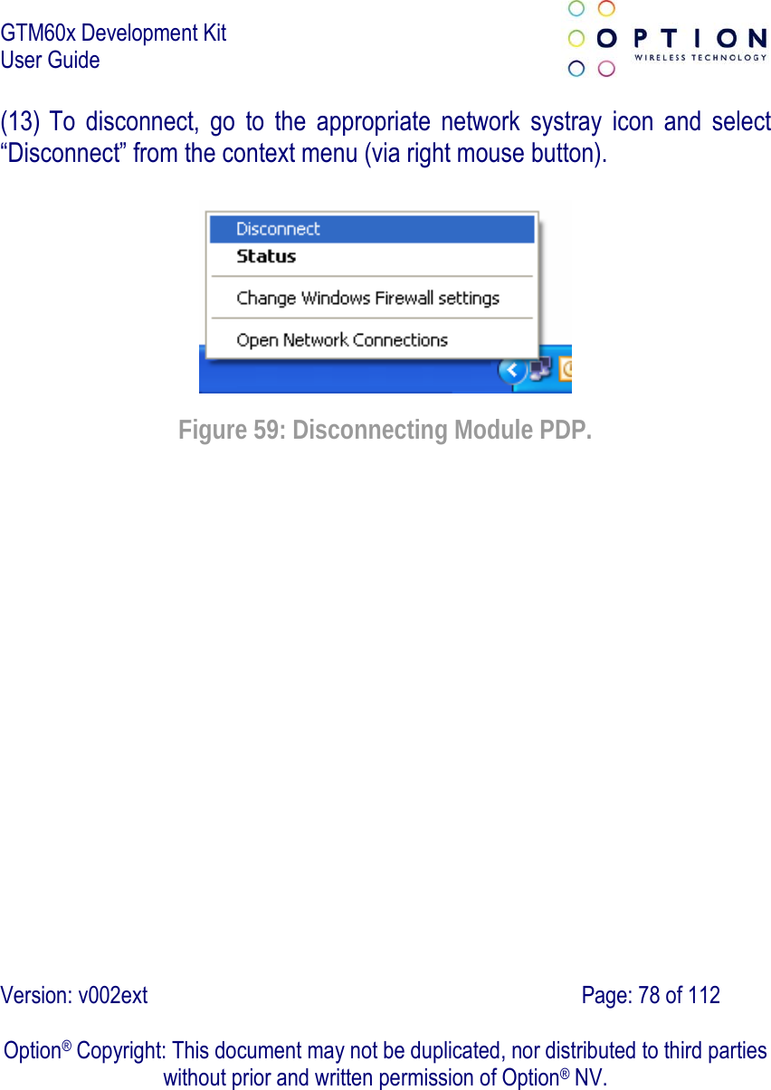
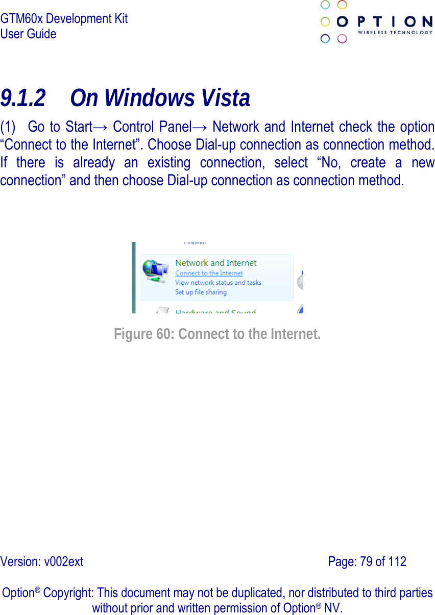
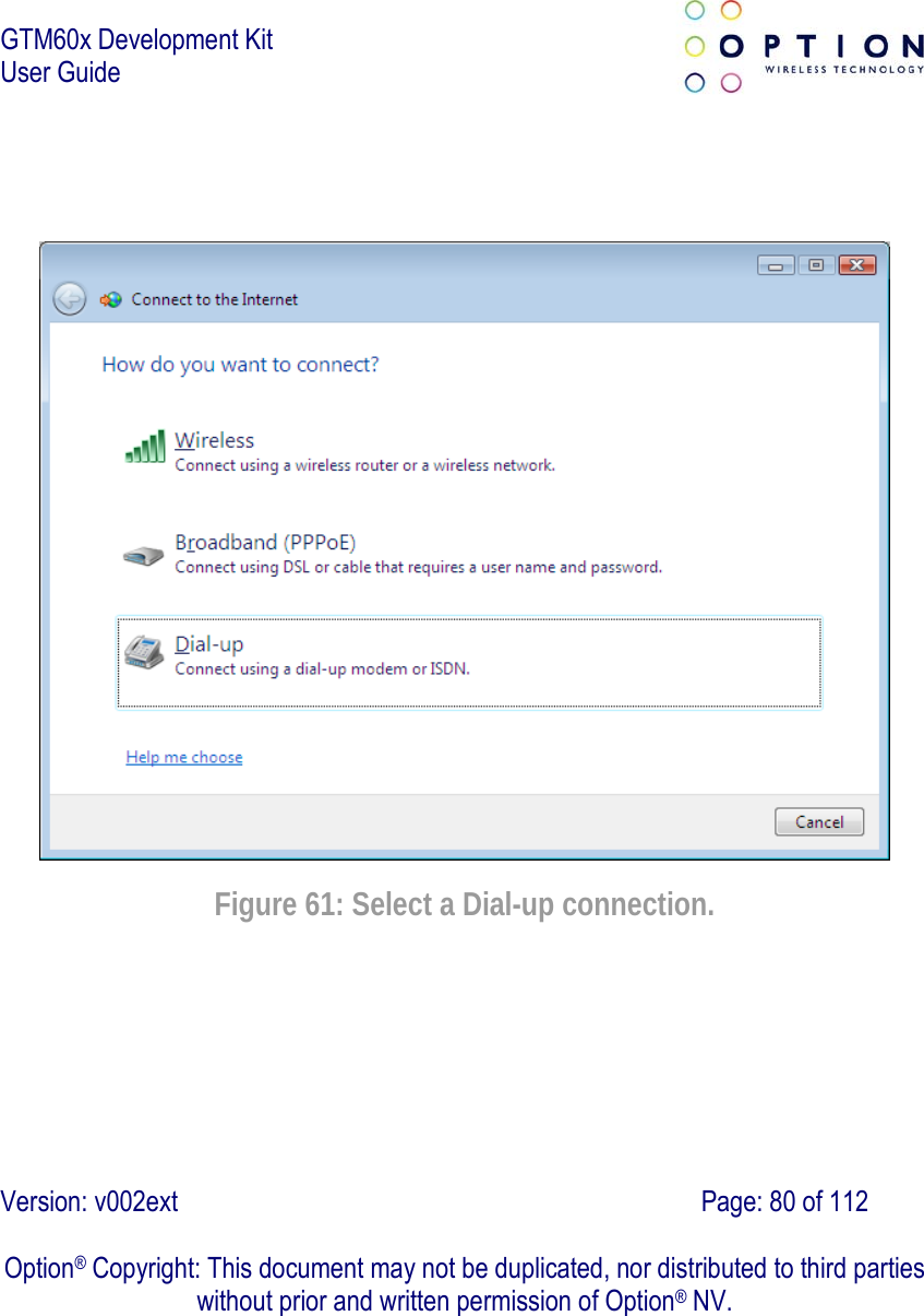
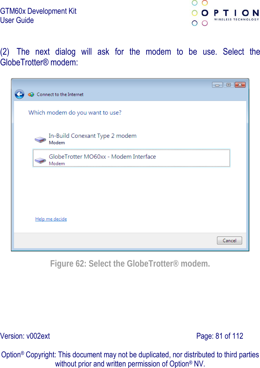
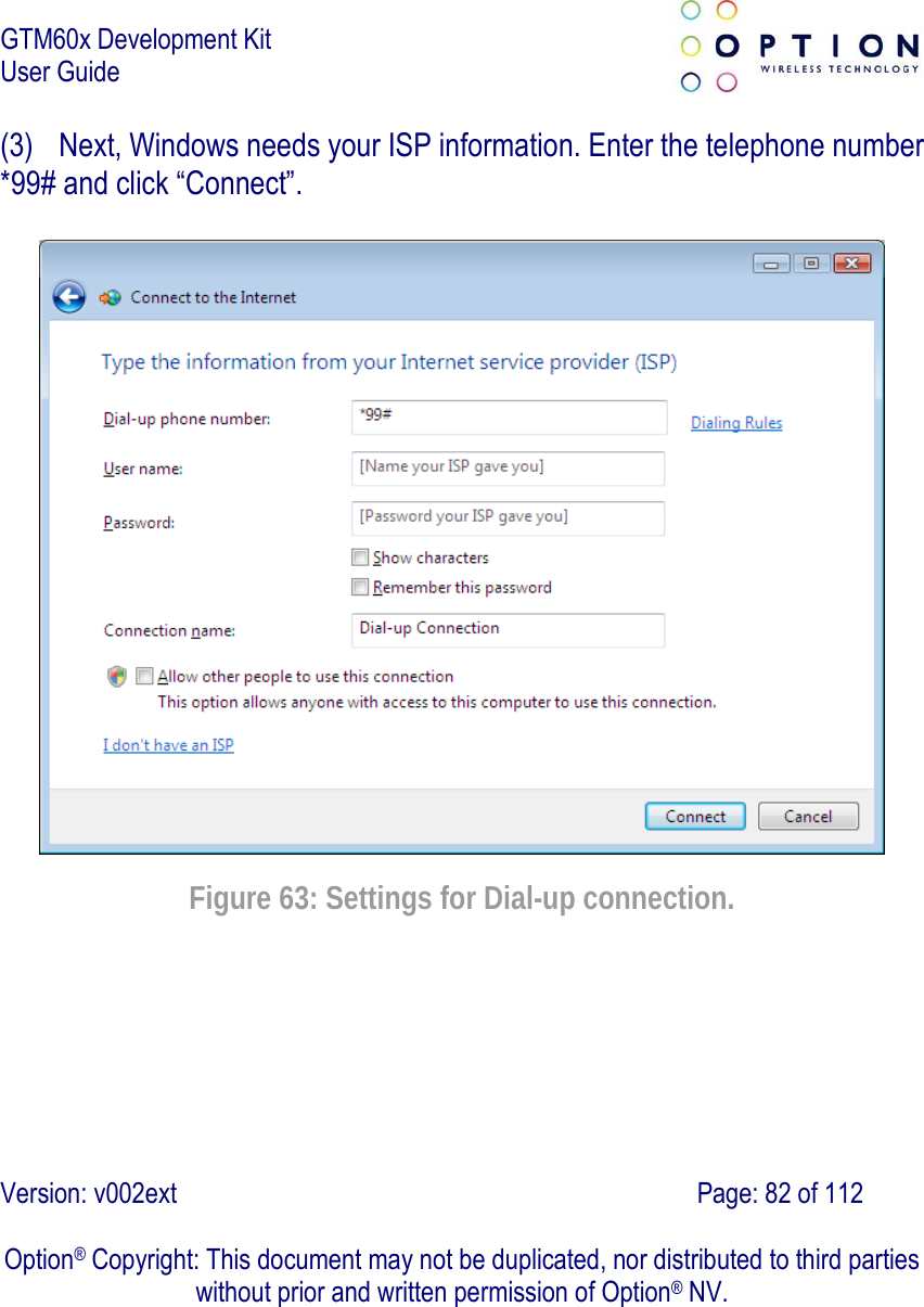
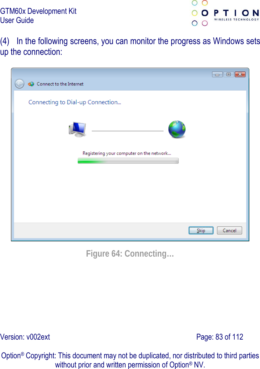
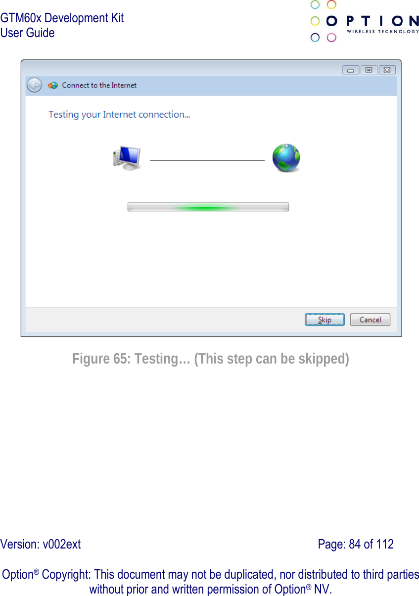
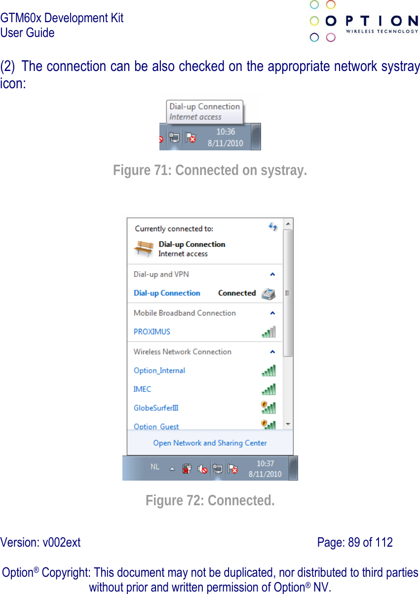
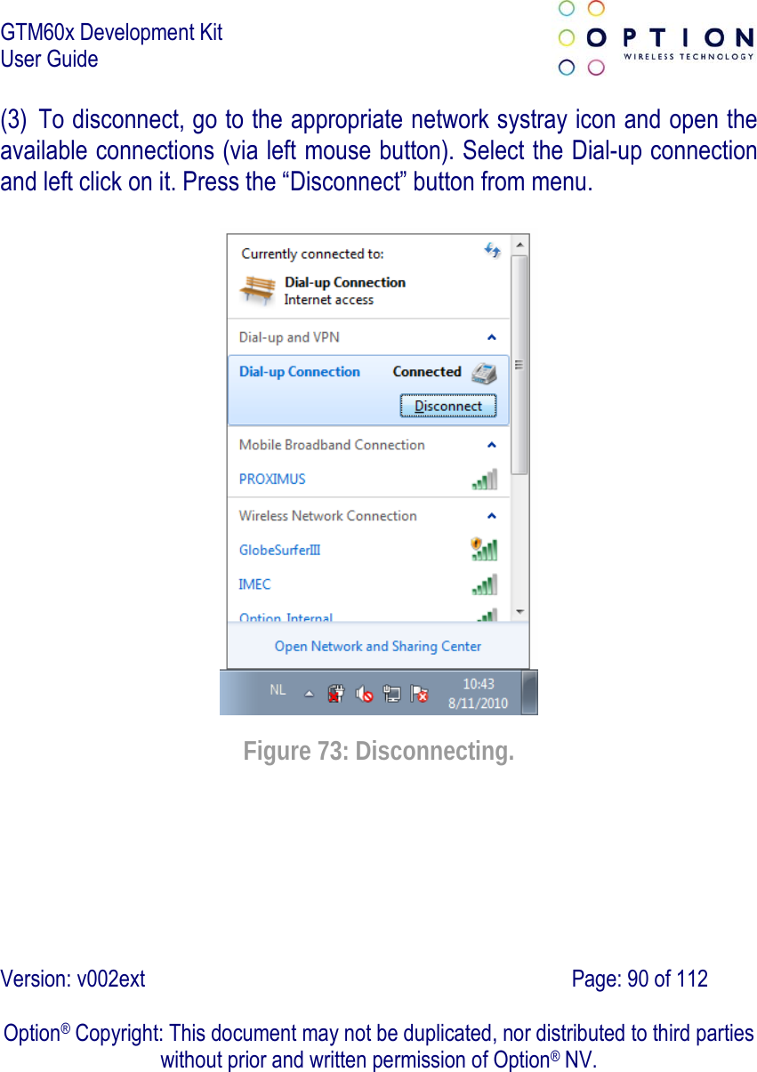
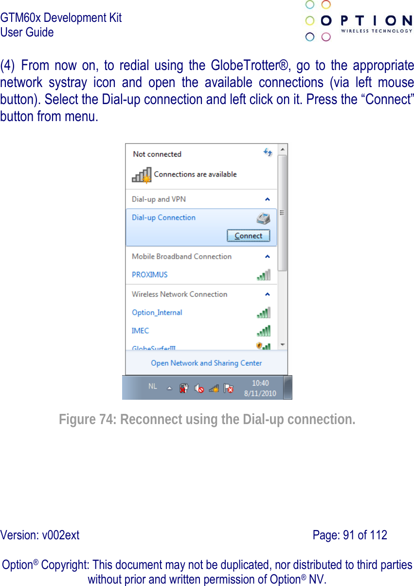
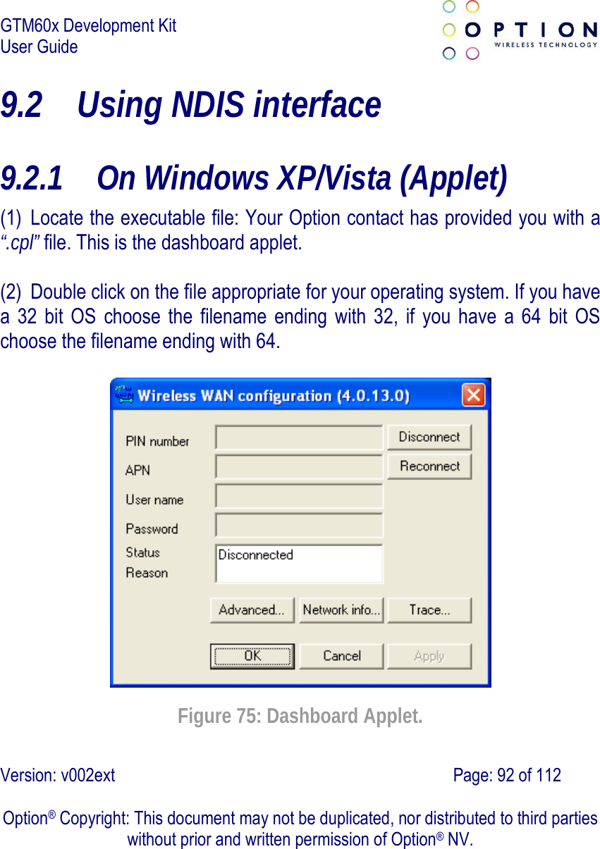
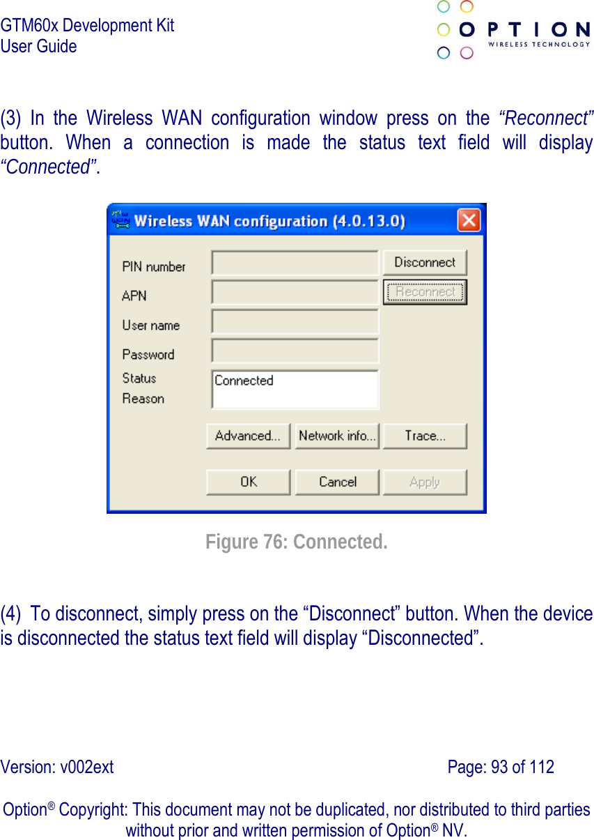
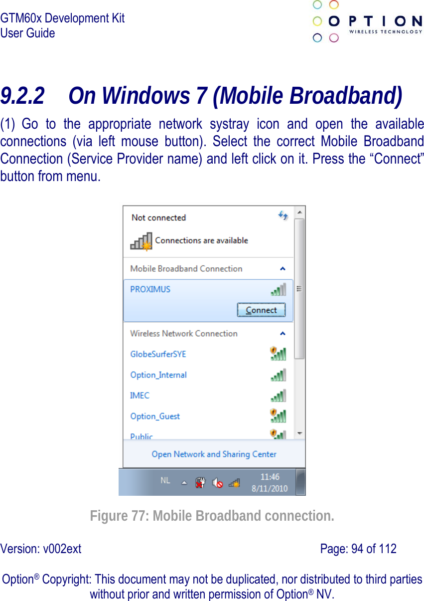
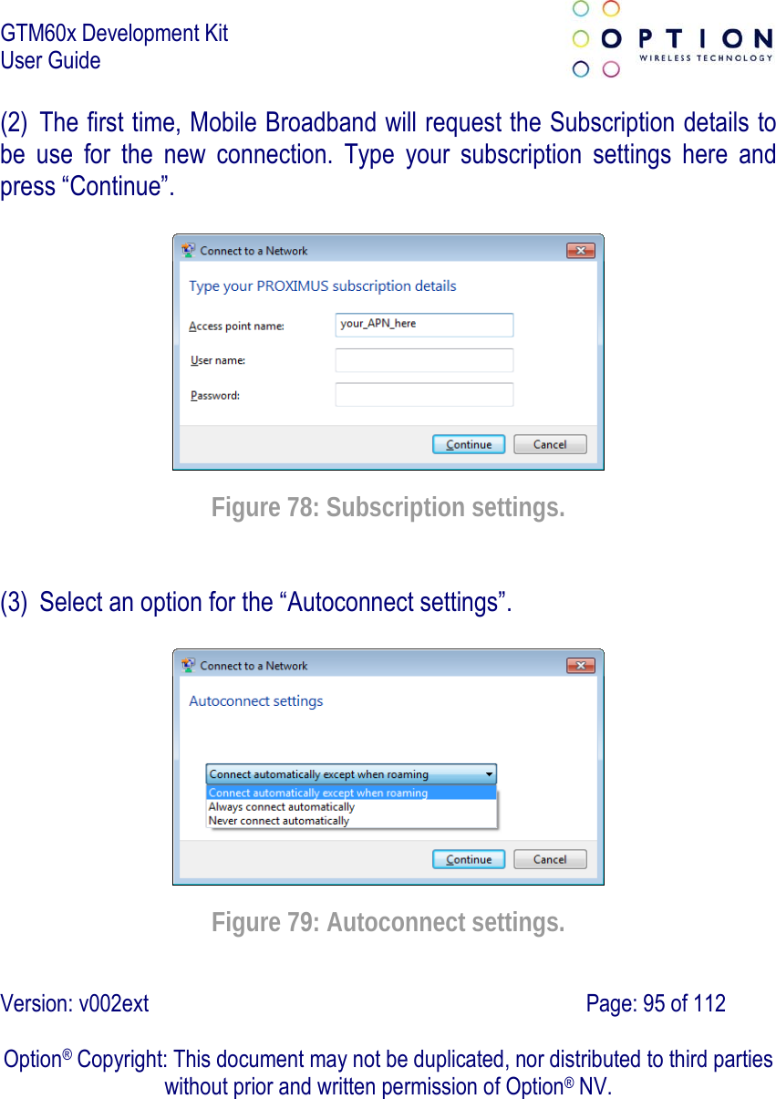
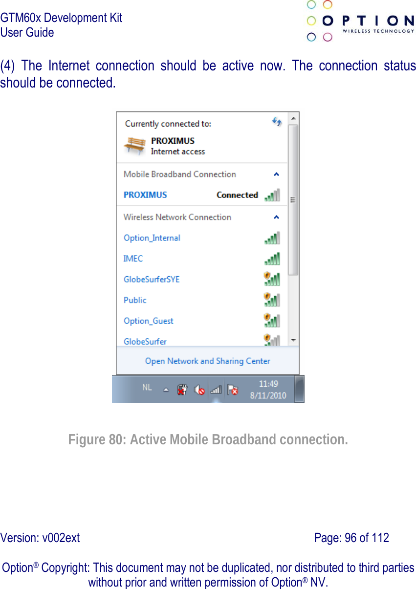
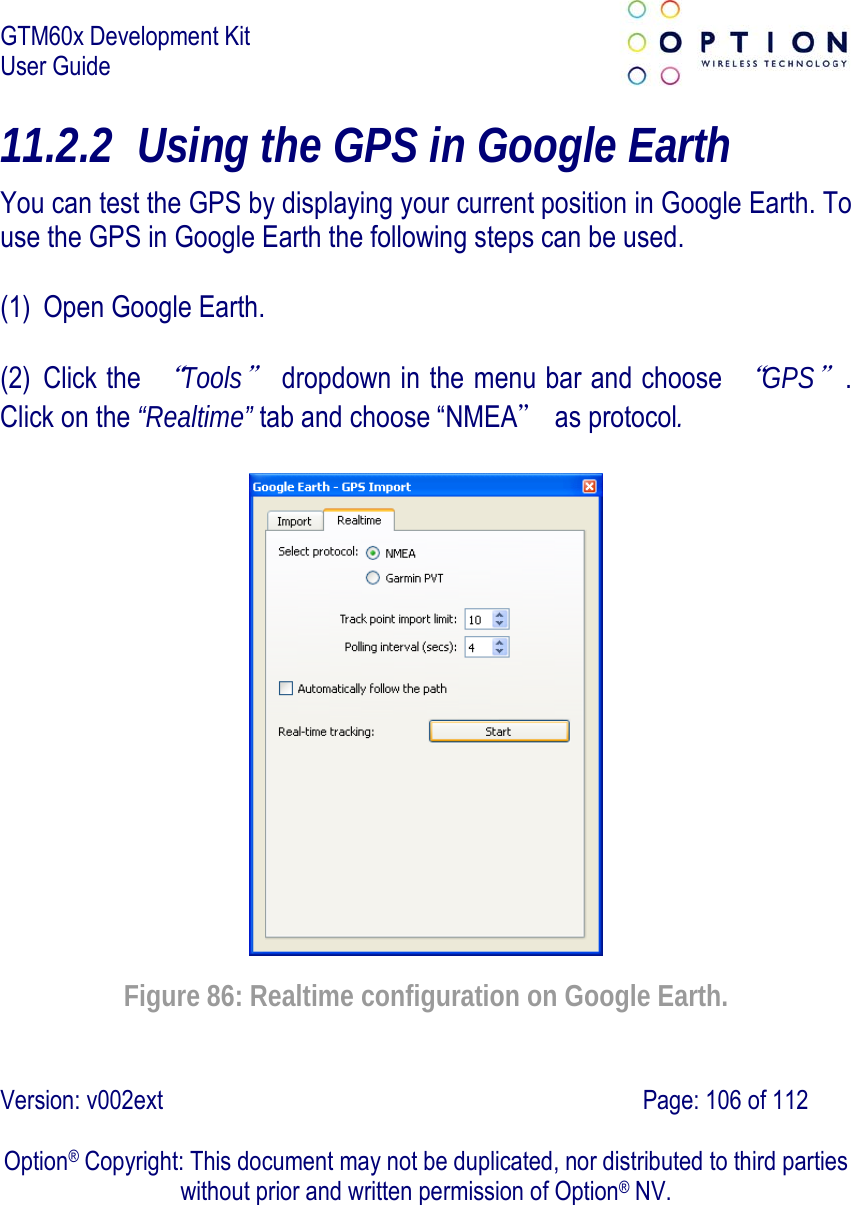
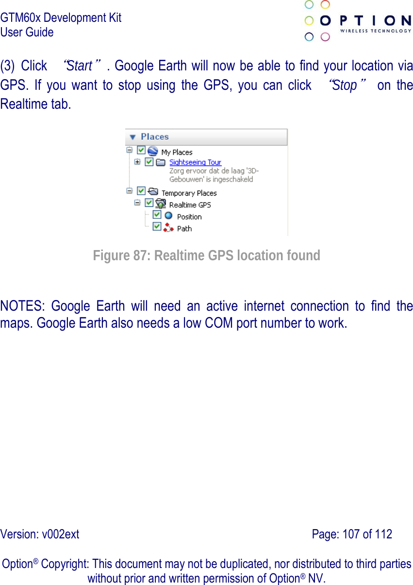
![GTM60x Development Kit User Guide Version: v002ext Page: 48 of 112 Option® Copyright: This document may not be duplicated, nor distributed to third parties without prior and written permission of Option® NV. 6 FIRMWARE UPGRADE NOTE: This section describes the upgrade to the latest firmware version of the GTM60x. At the time of this writing this was version 1.2.0.0. Check with your Option contact to acquire the latest firmware version. (1) Copy the latest firmware version to a known location. (2) Double click the compressed folder to open it. (3) Extract the two files contained in this compressed folder. (4) Browse to the folder where you extracted the firmware to. (5) Double click on the executable file “Blacktip_NYOS_fw_v[new_firmware_version].exe”. A window will open like in the screenshot below.](https://usermanual.wiki/Option/OMO6092/User-Guide-1474169-Page-48.png)