Option OMO6092 Nyos LGA CDMA Module User Manual TempConfidential ver01
Option NV Nyos LGA CDMA Module TempConfidential ver01
Option >
TempConfidential_User manual ver01

GTM601/609 Development Kit
User Guide
Ultra-thin 3G WWAN
Module in LGA package

GTM60x Development Kit
User Guide
Version: v002ext Page: 2 of 112
Option® Copyright: This document may not be duplicated, nor distributed to third parties
without prior and written permission of Option® NV.
VERSION HISTORY
Date Version Author Revision Approval
03/11/2010 V001int F. Arboleda
15/11/2010 V002ext F. Arboleda P. Vandeneede
S. Han Review

GTM60x Development Kit
User Guide
Version: v002ext Page: 3 of 112
Option® Copyright: This document may not be duplicated, nor distributed to third parties
without prior and written permission of Option® NV.
OVERVIEW AND PURPOSE
This document describes the GTM60x Module Development Kit hardware,
software and installation instructions. This user guide is applicable for the
following products:
Commercial
Name
Product
Number WIFI
2G Bands WCDMA
Bands
EVDO
Bands
GTM601W MO6012 No
800-
850/900/
1900/2100
No
GTM601E MO6011 No 900/2100 No
GTM609W MO6092 No
800-
850/900/
1900/2100
800/1900
GTM609U MO6093 No
All models
support 2G
quad band:
850Mhz
900Mhz
1800Mhz
1900Mhz 800-
850/1900 800/1900

GTM60x Development Kit
User Guide
Version: v002ext Page: 4 of 112
Option® Copyright: This document may not be duplicated, nor distributed to third parties
without prior and written permission of Option® NV.
CONFIDENTIALITY
All data and/or information contained in or disclosed by this document is
Option® NV confidential and proprietary and all respective rights are hereby
expressly reserved. By accepting this document, the recipient formally
acknowledges and agrees that this data and/or information is to be held in
strict confidence and is not to be used, copied, reproduced in whole or in part,
nor its contents revealed in any manner to others without prior and written
permission of Option® NV.

GTM60x Development Kit
User Guide
Version: v002ext Page: 5 of 112
Option® Copyright: This document may not be duplicated, nor distributed to third parties
without prior and written permission of Option® NV.
CONTENTS
1 WELCOME 7
2 FEATURES 9
3 GTM60x PACKAGE CONTENT 10
4 HARDWARE INSTALLATION 11
4.1 Hardware description 11
4.1.1 Detailed description 14
4.1.1.1 Controlling Switch 14
4.1.1.2 J14, J15 and J16 15
4.2 Installation 18
5 DRIVER INSTALLATION 21
5.1 Driver installation on Windows XP 21
5.1.1 General info: Driver set 21
5.1.2 Installation procedure 22
5.1.2.1 Automatic installation 22
5.1.2.2 Manual installation 23
5.2 Driver installation on Windows Vista 29
5.2.1 General info: Driver set 29
5.2.2 Installation procedure 30
5.2.2.1 Automatic installation 31
5.2.2.2 Manual installation 33
5.3 Driver installation on Windows 7 39
5.3.1 General info: Driver set 39
5.3.2 Installation procedure 40
5.3.2.1 Automatic installation 40
5.3.2.2 Manual installation 41
6 FIRMWARE UPGRADE 48

GTM60x Development Kit
User Guide
Version: v002ext Page: 6 of 112
Option® Copyright: This document may not be duplicated, nor distributed to third parties
without prior and written permission of Option® NV.
7 HOW TO SEND AT COMMANDS 51
8 GTM60x CONFIGURATION 61
8.1 Radio ON/OFF 61
8.2 RRC security 62
8.3 Preferred system 62
8.4 Access Point Name 62
8.5 SIM control 63
8.6 Registration 64
9 SETTING UP A PACKET SWITCHED DATA CALL 65
9.1 Using Modem interface (Dial-up) 65
9.1.1 On Windows XP 66
9.1.2 On Windows Vista 79
9.1.3 On Windows 7 88
9.2 Using NDIS interface 92
9.2.1 On Windows XP/Vista (Applet) 92
9.2.2 On Windows 7 (Mobile Broadband) 94
10 SET UP A GSM/UMTS VOICE CALL 98
11 GPS FEATURES 102
11.1 General 102
11.2 Set up a GPS connection 104
11.2.1 Enabling GPS positioning 105
11.2.2 Using the GPS in Google Earth 106
APPENDIX A: LIMITED WARRANTY 109
GTM60x Development Kit
User Guide
Version: v002ext Page: 7 of 112
Option® Copyright: This document may not be duplicated, nor distributed to third parties
without prior and written permission of Option® NV.
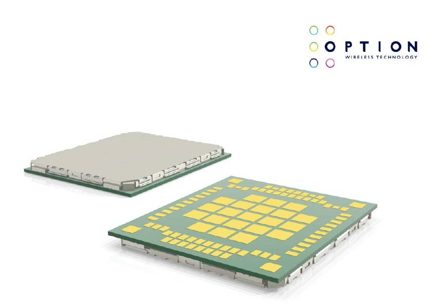
1 WELCOME
Figure 1: The GTM60x in LGA package
This GTM60x WWAN modem is the perfect solution for embedding 2G, 3G
and EVDO technology in small consumer electronics devices or broadband
M2M applications.
The GTM60x is capable of supporting HSDPA data rates of up to 14.4 Mbps
in downlink and up to 5.76 Mbps in uplink. The higher uplink speed is
particularly suitable for applications like video surveillance and file uploads. It
is also backward compatible.
The GTM609 is also capable of supporting EV-DO RevA data rates up to 3.1
Mbps in downlink and up to 1.8 Mbps in uplink.

GTM60x Development Kit
User Guide
Version: v002ext Page: 8 of 112
Option® Copyright: This document may not be duplicated, nor distributed to third parties
without prior and written permission of Option® NV.
For evaluation purposes the GTM60x modules are housed on an evaluation
board, offering a convenient evaluation and development platform. This
document describes the Module Development Kit hardware and software
installation, and basic usage instructions for Windows® XP, Vista and 7.
Design specific information for the modules is outside the scope of this
document and can be found in the GTM60x integration package.
To make a successful connection to the internet, the following prerequisites
are assumed:
GTM60x Development Kit EVB R1.
Live Network connection.
Activated (U)SIM for the available network.
Host platform with an USB host controller (e.g. laptop or PC desktop).

GTM60x Development Kit
User Guide
Version: v002ext Page: 9 of 112
Option® Copyright: This document may not be duplicated, nor distributed to third parties
without prior and written permission of Option® NV.
2 FEATURES
Due to its ultra-thin form factor and excellent heat dissipation characteristics
this is the perfect module for integration in small consumer electronics
devices or broadband M2M applications. The GPS and voice capabilities
give this module a unique position. The new and improved footprint facilitates
soldering.
The Development Kit consists of a main evaluation board (cradle) which
provides a standard USB interface, a SIM card holder, an external power
supply and the on board GTM60x module. With this board it is possible to
connect the GTM60x module package to any standard USB host controller.
To get your module working correctly, please follow the installation
instructions carefully in the correct order, starting with sections 4 and 5, after
which you can proceed with the following sections.

GTM60x Development Kit
User Guide
Version: v002ext Page: 10 of 112
Option® Copyright: This document may not be duplicated, nor distributed to third parties
without prior and written permission of Option® NV.
3 GTM60x PACKAGE CONTENT
Your Module Development Kit comes with the following items:
Evaluation board containing the GTM60x module.
USB cable.
Power adaptor (5VDC / 2A @ 100-240V).
The module will have the latest firmware which was available during the
assembly of this development kit. Please check with your Option point of
contact for the latest available firmware. Drivers and the dashboard applet
will be available via your Option point of contact.
To set up a successful data connection to the internet you will need to have
mobile network coverage and an activated SIM card from your local operator.

GTM60x Development Kit
User Guide
Version: v002ext Page: 11 of 112
Option® Copyright: This document may not be duplicated, nor distributed to third parties
without prior and written permission of Option® NV.
4 HARDWARE INSTALLATION
4.1 Hardware description
Figure 2: Evaluation board

GTM60x Development Kit
User Guide
Version: v002ext Page: 12 of 112
Option® Copyright: This document may not be duplicated, nor distributed to third parties
without prior and written permission of Option® NV.
Points of interest (See Figure 2):
1) GTM60x Module.
2) Power LED: Indicates that GTM60x is powered.
3) Registration and USB activity LED: This LED indicates that the
module has registered to the mobile network when it is on
continuously. Also indicates USB communication activity when the
LED is blinking.
4) SIM card holder.
5) 2.5mm Audio jack and headset (for voice enabled modules).
6) SW1: On key. Acts as a power on/off button. See J2 (20).
7) SW2: Reset button.
8) SW3: Audio CODEC chip reset button.
9) Power plug.
10) Mini USB connector (male).
11) Battery plug.
12) Controlling Switch.**
13) Main antenna.
14) External antenna connector for main antenna.*
15) Secondary/Diversity antenna.
16) External antenna connector for secondary antenna.*
17) GPS antenna.
18) External antenna connector for GPS antenna.*

GTM60x Development Kit
User Guide
Version: v002ext Page: 13 of 112
Option® Copyright: This document may not be duplicated, nor distributed to third parties
without prior and written permission of Option® NV.
19) J1: Jumper to enable or disable the power circuits next to the mini
USB connector. By default the power circuits are enabled (no
jumper cap). The power circuit should be disabled when using the
battery connector to power de GTM60x by short circuiting the
jumper.
20) J2: Jumper to automatically power the modem when connected to
any of the three possible means (9, 10 or 11). If this jumper is not
short circuited the GTM60x will be only powered when the “On key”
(7) is pressed.
21) J3: Jumper for current measurements. If no measurement is need
this jumper needs to be short circuited in order to power the
GTM60x.
22) J4: Jumper to enable to bulk capacitors (orange capacitors). These
bulk capacitors are needed when the GTM60x is powered by USB
or by the power plug; in this case the jumper has to be short
circuited. If batteries are used, the bulk capacitors should be
disabled by removing the jumper cap (this jumper cap can be use
on J1 to disable the power circuits).
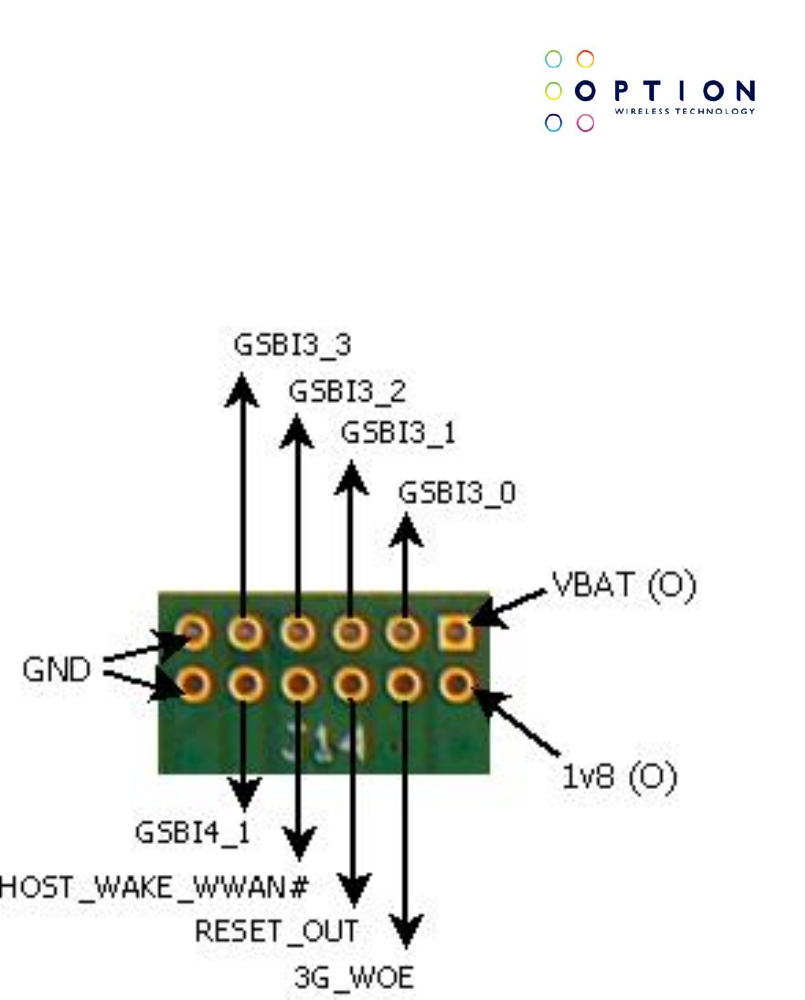
23) J14: Connection to access GSBI port 3.**
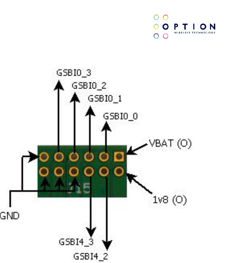
24) J15: Connection to access GSBI ports 0 and 4.**
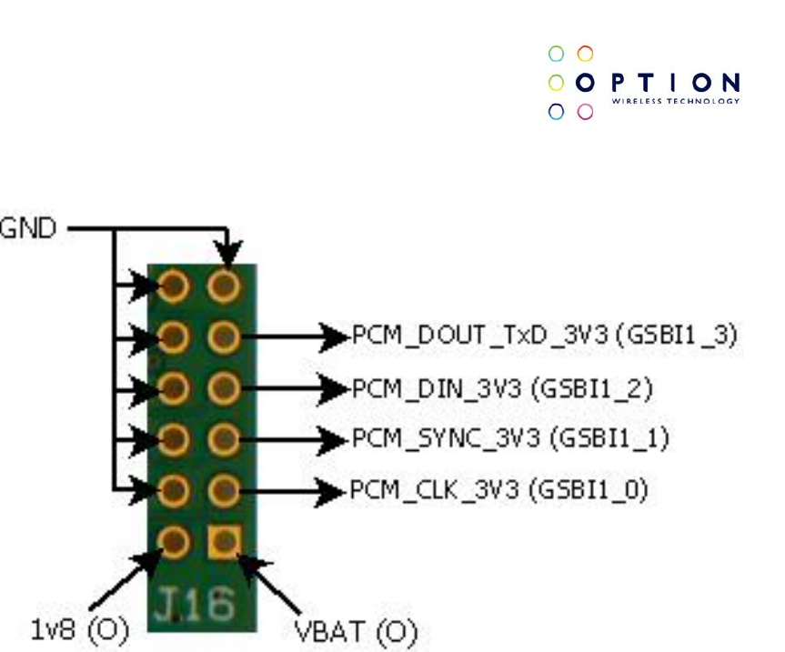
25) J16: Connection to add an external PCM codec (GSBI port 1).**
* When using this external antenna connector the printed antenna will be
automatically disabled.
**See detailed description.

GTM60x Development Kit
User Guide
Version: v002ext Page: 14 of 112
Option® Copyright: This document may not be duplicated, nor distributed to third parties
without prior and written permission of Option® NV.
4.1.1 Detailed description
4.1.1.1 Controlling Switch
Figure 3: Controlling Switch
Switches:
(1) MICMUTE: Switch to mute the microphone on the audio jack. Default
value: ON.
(2) EARMUTE: Switch to mute the ear piece on the audio jack. Default value:
ON.
(3) COMPSEL: Selection of bit format. Default value: ON.
(4) W.DISABLE: Turn ON/OFF the radio on the module. Default value: OFF.
GTM60x Development Kit
User Guide
Version: v002ext Page: 15 of 112
Option® Copyright: This document may not be duplicated, nor distributed to third parties
without prior and written permission of Option® NV.
4.1.1.2 J14, J15 and J16
Figure 4: J14 Specification
GTM60x Development Kit
User Guide
Version: v002ext Page: 16 of 112
Option® Copyright: This document may not be duplicated, nor distributed to third parties
without prior and written permission of Option® NV.
Figure 5: J15 Specification
GTM60x Development Kit
User Guide
Version: v002ext Page: 17 of 112
Option® Copyright: This document may not be duplicated, nor distributed to third parties
without prior and written permission of Option® NV.
Figure 6: J16 Specification.
NOTE: 3v3 will be transformed into 1v8 by an on board level translator. This
level translator is located on the development board and not on the GTM60x.

GTM60x Development Kit
User Guide
Version: v002ext Page: 18 of 112
Option® Copyright: This document may not be duplicated, nor distributed to third parties
without prior and written permission of Option® NV.
4.2 Installation
Start by carefully inserting your SIM card in the SIM card holder (4). Do this
by pushing the SIM card in the cardholder until it clicks into place.
Figure 7: SIM card holder.
Next, connect the power adaptor to the power plug (9). After this, connect the
mini USB connector to the USB plug (10) on the evaluation board. Connect
the other end of the USB cable into your computer. If voice is necessary,
insert your headset on the audio jack (5).

GTM60x Development Kit
User Guide
Version: v002ext Page: 19 of 112
Option® Copyright: This document may not be duplicated, nor distributed to third parties
without prior and written permission of Option® NV.
Figure 8: Power and USB connectors.
Figure 9: Audio jack and Headset.

GTM60x Development Kit
User Guide
Version: v002ext Page: 20 of 112
Option® Copyright: This document may not be duplicated, nor distributed to third parties
without prior and written permission of Option® NV.
Be sure the W. Disable switch on the controlling switch (12) is on the OFF
position to have the radio ON. If Jumper J2 (20) is not short circuited, press
the on key (6). At this point the host PC should detect your module.
Figure 10: Switch 4 (W. Disable) is in OFF position.
Figure 11: J2 and ON key
You can now proceed with section 5 for driver installation instructions.
GTM60x Development Kit
User Guide
Version: v002ext Page: 21 of 112
Option® Copyright: This document may not be duplicated, nor distributed to third parties
without prior and written permission of Option® NV.
5 DRIVER INSTALLATION
5.1 Driver installation on Windows XP
We currently provide one set of drivers for Windows XP/Vista and one set for
Windows 7. These driver sets contain drivers that control the module. The
driver set described in this section supports, Windows XP 32/64 bit edition
and Windows Vista 32/64 bit edition. The driver name should be 5.2.x.x.
5.1.1 General info: Driver set
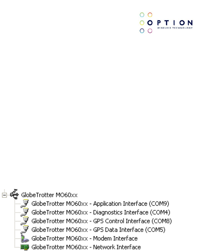
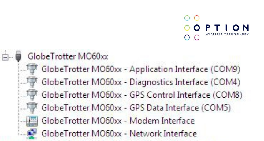
On successful installation of all drivers, the device manager will show the
following installed devices. Please configure the device manager by selecting
“View”, “Devices by connection”. Expand the tree to show the USB devices.
Be aware that the list of devices may differ depending on the module
configuration.
Figure 12: Ports occupied by the GTM60x

GTM60x Development Kit
User Guide
Version: v002ext Page: 22 of 112
Option® Copyright: This document may not be duplicated, nor distributed to third parties
without prior and written permission of Option® NV.
5.1.2 Installation procedure
Make sure you have a clean system before proceeding with the installation
procedure. At this point you should copy the driver folder to a known location
on your hard disk drive.
NOTE: At the time of this writing the latest driver version was version 5.2.1.0.
Check with your Option contact to acquire the latest driver version. You can
now proceed with the manual installation.
5.1.2.1 Automatic installation
(1) The automatic driver installation is very similar in Windows XP, Windows
Vista and Windows 7. Without the cradle being connected, run the driver
installer “setup.exe” provided by your Option contact. The setup application
runs until completion. This process can take up to two or three minutes.
To be certain that the setup has finished, you can double-check in Task
Manager if it is still running. Task Manager can be started up by pressing
control-alt-delete and selecting “Start Task Manager”. Your list should not
display “setup.exe”.
(2) Connect the GTM60x to the laptop as described in section 4. The
installation of the drivers runs automatically. No user interaction is required.
GTM60x Development Kit
User Guide
Version: v002ext Page: 23 of 112
Option® Copyright: This document may not be duplicated, nor distributed to third parties
without prior and written permission of Option® NV.
You can verify if the device is installed by opening Device Manager. Please
configure it in the menu via “View”, “Devices by connection”. Expand the tree
until you see the GlobeTrotter® module as shown in Figure 12.
5.1.2.2 Manual installation
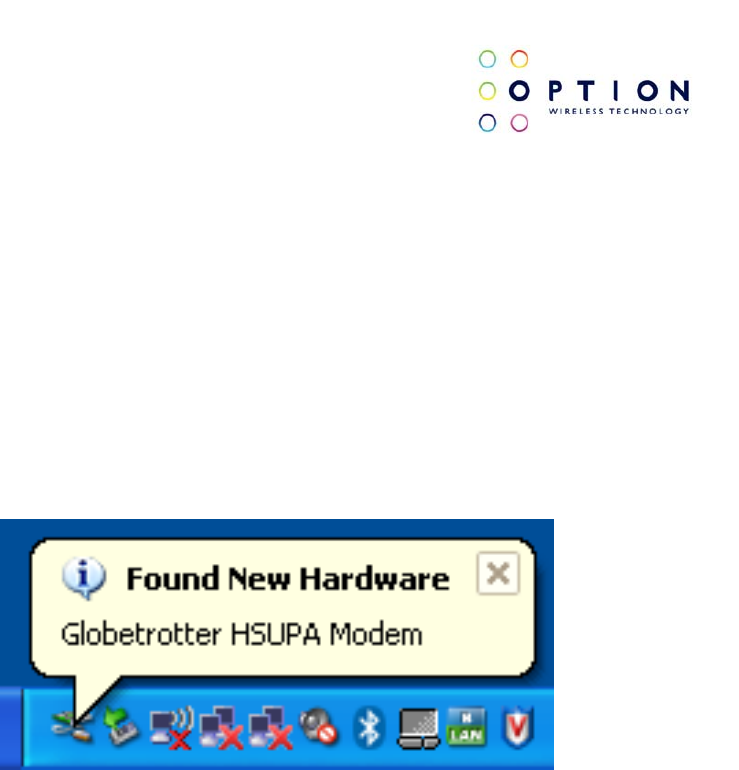
(1) If you have not already done so, install and connect the cradle as
described in section 4. The unit is connected correctly only if the “Found New
Hardware” balloon and subsequently the “Welcome to the Found New
Hardware Wizard” appear.
Figure 13: Balloon message “Found New Hardware”
GTM60x Development Kit
User Guide
Version: v002ext Page: 24 of 112
Option® Copyright: This document may not be duplicated, nor distributed to third parties
without prior and written permission of Option® NV.
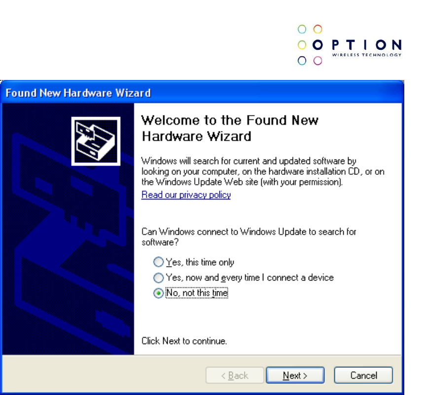
Figure 14: Welcome to the Found New Hardware Wizard
(2) In the first dialog (“Can Windows connect to Windows Update to search
for software?”), select “No, not this time”
GTM60x Development Kit
User Guide
Version: v002ext Page: 25 of 112
Option® Copyright: This document may not be duplicated, nor distributed to third parties
without prior and written permission of Option® NV.
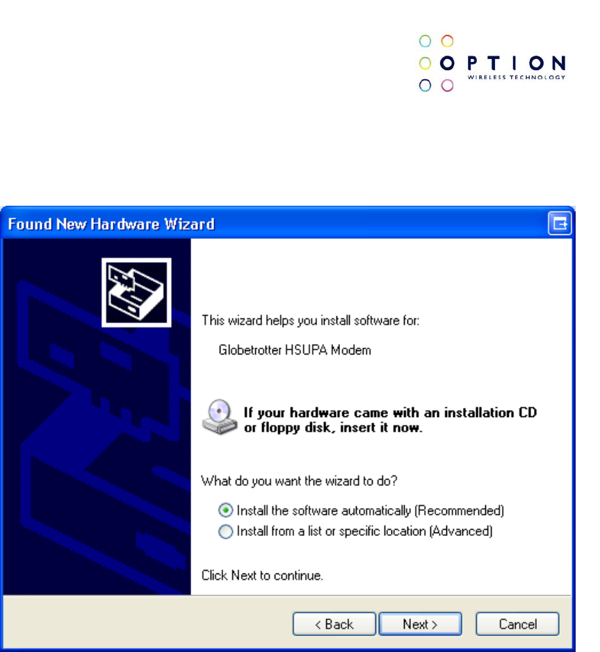
(3) In the next dialog, select “Install software automatically (Recommended)”.
At this point make sure the CD-ROM with drivers is inserted in your optical
drive.
Figure 15: Install the software automatically (Recommended)
GTM60x Development Kit
User Guide
Version: v002ext Page: 26 of 112
Option® Copyright: This document may not be duplicated, nor distributed to third parties
without prior and written permission of Option® NV.
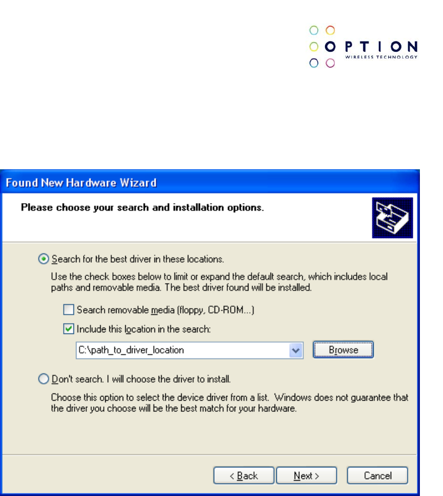
If you know where the drivers are located, you can select “Install from a list
or specific location (Advanced)”. In this case ensure you select the option
“Include this location in the search:” in the next screen, and enter the correct
path to your drivers.
Figure 16: Install from a list or specific location (Advanced)
GTM60x Development Kit
User Guide
Version: v002ext Page: 27 of 112
Option® Copyright: This document may not be duplicated, nor distributed to third parties
without prior and written permission of Option® NV.
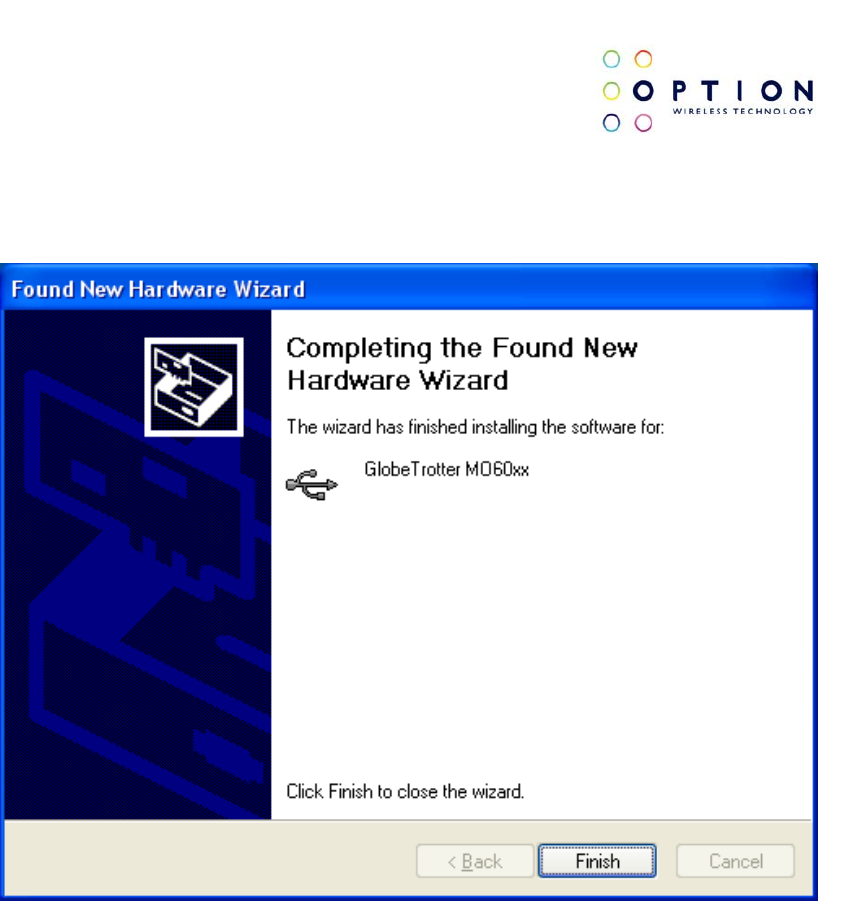
(4) Click “Finish” in the next screen “Completing the Found New Hardware
Wizard”.
Figure 17: Completing the Found New Hardware Wizard

GTM60x Development Kit
User Guide
Version: v002ext Page: 28 of 112
Option® Copyright: This document may not be duplicated, nor distributed to third parties
without prior and written permission of Option® NV.
(5) Repeat steps 3 to 4 for all drivers. Windows will start a wizard for each
interface.
(6) On successful installation of all drivers, the device manager will show the
following typical installed devices. Please configure the device manager by
selecting “View”, “Devices by connection” (See Figure 12).

GTM60x Development Kit
User Guide
Version: v002ext Page: 29 of 112
Option® Copyright: This document may not be duplicated, nor distributed to third parties
without prior and written permission of Option® NV.
5.2 Driver installation on Windows
Vista
We currently provide one set of drivers for Windows XP/Vista and one set for
Windows 7. These driver sets contain drivers that control the module. The
driver set described in this section supports, Windows XP 32/64 bit edition
and Windows Vista 32/64 bit edition. The driver name should be 5.2.x.x.
5.2.1 General info: Driver set
On successful installation of all drivers, the device manager will show the
following installed devices. Please configure the device manager by selecting
“View”, “Devices by connection”. Expand the tree to show the USB devices.
GTM60x Development Kit
User Guide
Version: v002ext Page: 30 of 112
Option® Copyright: This document may not be duplicated, nor distributed to third parties
without prior and written permission of Option® NV.
Figure 18: Ports occupied by the GTM60x
5.2.2 Installation procedure
Make sure you have a clean system before proceeding with the installation
procedure. At this point you should copy the driver folder to a known location
on your hard disk drive.
NOTE: At the time of this writing the latest driver version was version 5.2.1.0.
Check with your Option contact to acquire the latest driver version. You can
now proceed with the manual installation.

GTM60x Development Kit
User Guide
Version: v002ext Page: 31 of 112
Option® Copyright: This document may not be duplicated, nor distributed to third parties
without prior and written permission of Option® NV.
5.2.2.1 Automatic installation
(1) Without the cradle being connected, run the driver installer “setup.exe”
provided by your Option contact. The setup application runs until completion.
This process can take up to two or three minutes.
Starting the setup application will pop up the User Account Control security
feature of Windows Vista. Allow the program to run (Option: Allow. I trust this
program. I know where it’s from or I’ve used it before.)
The setup application runs until completion. To be certain that setup has
finished, you can double-check in Task Manager if it is still running. Task
Manager can be started up by pressing control-alt-delete and selecting “Start
Task Manager”. Your list should not display “setup.exe”.
(2) Connect the GTM60x to the laptop as described in section 4. Windows
Vista will recognize the device and start installing drivers. No user interaction
is required.
Figure 19: The device is recognized.
GTM60x Development Kit
User Guide
Version: v002ext Page: 32 of 112
Option® Copyright: This document may not be duplicated, nor distributed to third parties
without prior and written permission of Option® NV.
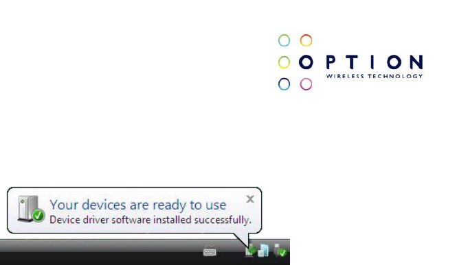
Clicking on this popup will show the progress of the installation. When all the
drivers are installed, Vista will inform you that your devices are ready to use.
Figure 20: The devices are ready to be used.
You can verify if the device is installed by opening Device Manager. Please
configure it in the menu via “View”, “Devices by connection”. Expand the tree
until you see the GlobeTrotter® module as shown in Figure 18.
GTM60x Development Kit
User Guide
Version: v002ext Page: 33 of 112
Option® Copyright: This document may not be duplicated, nor distributed to third parties
without prior and written permission of Option® NV.
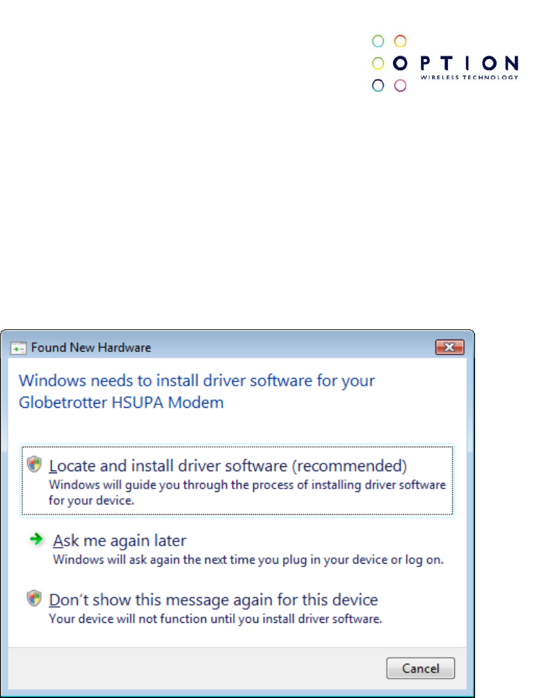
5.2.2.2 Manual installation
(1) If you have not already done so, install and connect the cradle as
described in section 4. The unit is connected correctly only if the “Found New
Hardware” screen appears.
(2) Choose “Locate and install driver software (recommended)” to install the
driver manually.
Figure 21: Windows needs to install driver software
GTM60x Development Kit
User Guide
Version: v002ext Page: 34 of 112
Option® Copyright: This document may not be duplicated, nor distributed to third parties
without prior and written permission of Option® NV.
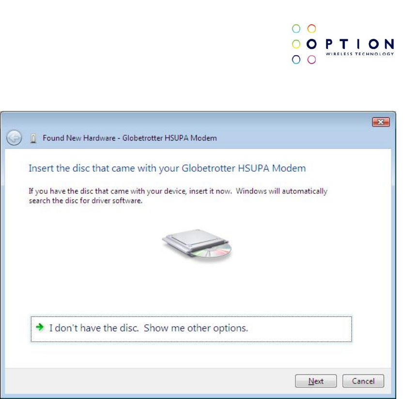
(3) Next, select “I don’t have the disc. Show me other options”.
Figure 22: More installation options.
GTM60x Development Kit
User Guide
Version: v002ext Page: 35 of 112
Option® Copyright: This document may not be duplicated, nor distributed to third parties
without prior and written permission of Option® NV.
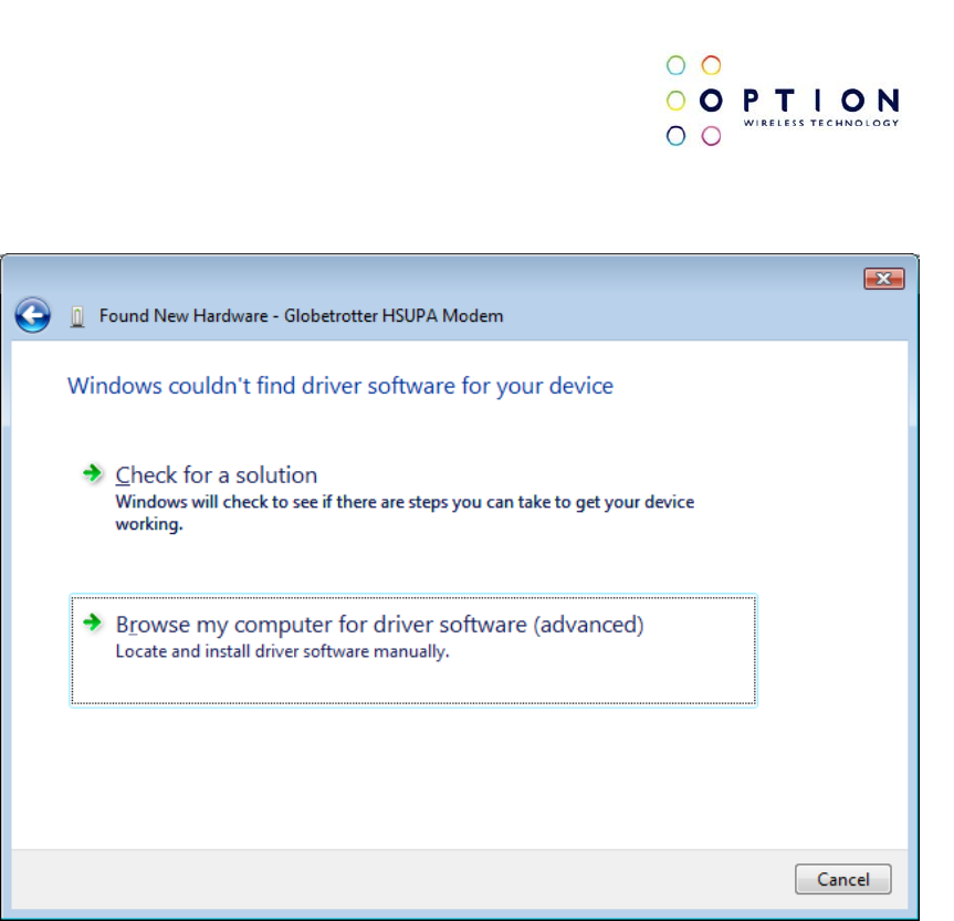
(4) Select “Browse my computer for driver software (advanced).”
Figure 23: Browse my computer for driver software (advanced)
GTM60x Development Kit
User Guide
Version: v002ext Page: 36 of 112
Option® Copyright: This document may not be duplicated, nor distributed to third parties
without prior and written permission of Option® NV.
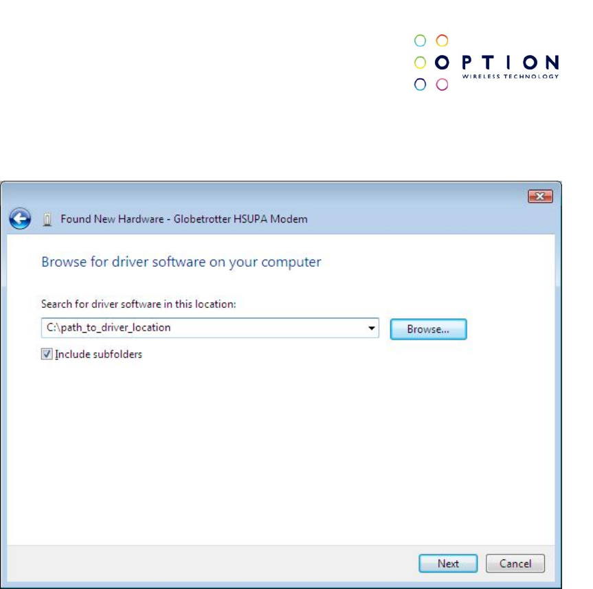
(5) You can now enter the path where the driver software is located. Press
“Browse” to find the appropriate driver.
Figure 24: Browse for driver software on your computer
(6) Windows will now start with the installation of driver software.
GTM60x Development Kit
User Guide
Version: v002ext Page: 37 of 112
Option® Copyright: This document may not be duplicated, nor distributed to third parties
without prior and written permission of Option® NV.
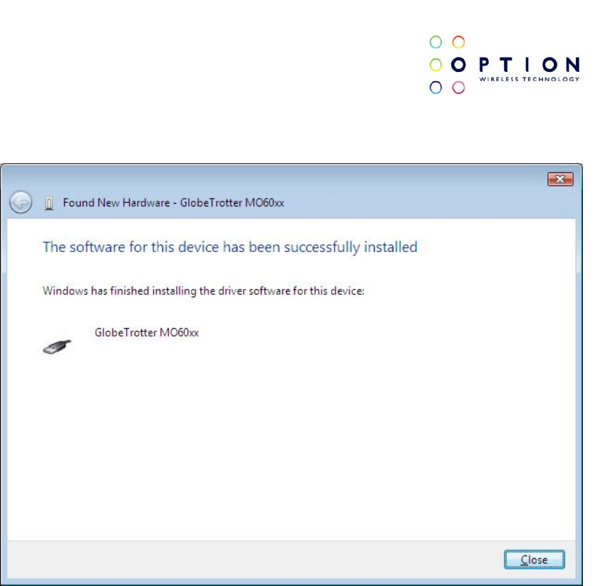
(7) The wizard will notify you when the installation is successful.
Figure 25: The software for this device has been successfully installed.
(8) Repeat steps 2 to 7 for all drivers. Windows will start a wizard for each
interface.

GTM60x Development Kit
User Guide
Version: v002ext Page: 38 of 112
Option® Copyright: This document may not be duplicated, nor distributed to third parties
without prior and written permission of Option® NV.
(9) On successful installation of all drivers, the device manager will show the
following typical installed devices. Please configure the device manager by
selecting “View”, “Devices by connection”. Expand the tree to show the USB
devices (See Figure 18).
GTM60x Development Kit
User Guide
Version: v002ext Page: 39 of 112
Option® Copyright: This document may not be duplicated, nor distributed to third parties
without prior and written permission of Option® NV.
5.3 Driver installation on Windows 7
We currently provide one set of drivers for Windows XP/Vista and one set for
Windows 7. These driver sets contain drivers that control the module. The
driver set described in this section supports, Windows 7 32/64 bit edition.
The driver name should be 5.1.x.x.
5.3.1 General info: Driver set
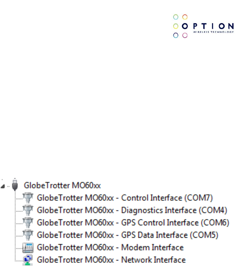
On successful installation of all drivers, the device manager will show the
following installed devices. Please configure the device manager by selecting
“View”, “Devices by connection”. Expand the tree to show the USB devices.
Figure 26: Ports occupied by the GTM60x

GTM60x Development Kit
User Guide
Version: v002ext Page: 40 of 112
Option® Copyright: This document may not be duplicated, nor distributed to third parties
without prior and written permission of Option® NV.
5.3.2 Installation procedure
Make sure you have a clean system before proceeding with the installation
procedure. At this point you should copy the driver folder to a known location
on your hard disk drive.
NOTE: At the time of this writing the latest driver version was version
5.1.38.0 (Unsigned). Check with your Option contact to acquire the latest
driver version. You can now proceed with the manual installation.
5.3.2.1 Automatic installation
(1) Without the cradle being connected, run the driver installer “setup.exe”
provided by your Option contact. The setup application runs until completion.
This process can take up to two or three minutes.
Starting the setup application will pop up the User Account Control security
feature of Windows 7. Allow the program to run (Option: Allow. I trust this
program. I know where it’s from or I’ve used it before.)
The setup application runs until completion. To be certain that setup has
finished, you can double-check in Task Manager if it is still running. Task
Manager can be started up by pressing control-alt-delete and selecting “Start
Task Manager”. Your list should not display “setup.exe”.
GTM60x Development Kit
User Guide
Version: v002ext Page: 41 of 112
Option® Copyright: This document may not be duplicated, nor distributed to third parties
without prior and written permission of Option® NV.
(2) Connect the GTM60x to the laptop as described in section 4. Windows
Vista will recognize the device and start installing drivers. No user interaction
is required.
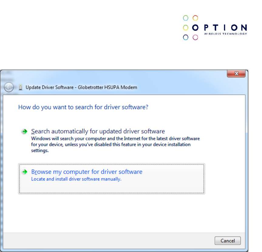
5.3.2.2 Manual installation
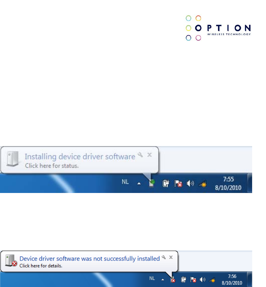
(1) If you have not already done so, install and connect the cradle as
described in section 4. Windows will detect new hardware.
Figure 27: Installing device driver software.
(2) Windows will fail to install the correct drivers
Figure 28: Failing installing the correct drivers.
GTM60x Development Kit
User Guide
Version: v002ext Page: 42 of 112
Option® Copyright: This document may not be duplicated, nor distributed to third parties
without prior and written permission of Option® NV.
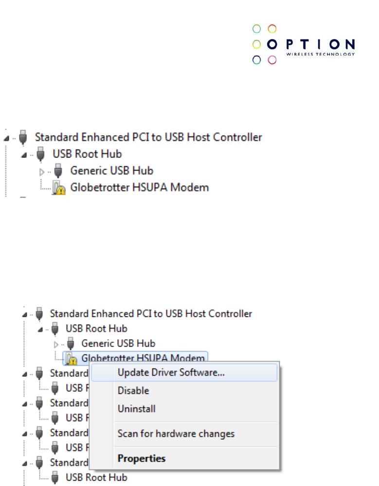
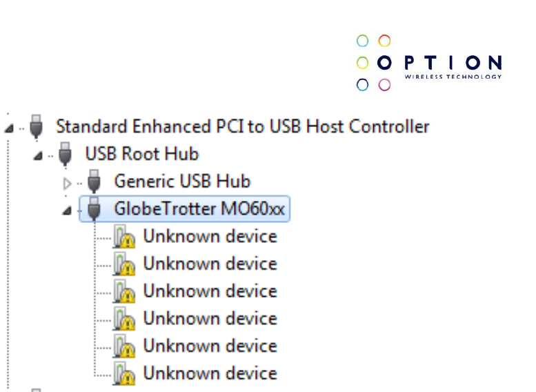
(3) Open the device manager by searching for it in the start menu search
field and clicking on it.
Figure 29: Device drivers not installed
(4) Right click “Globetrotter HSUPA Modem” and choose “Update Driver
Software”.
Figure 30: Update Driver Software.
GTM60x Development Kit
User Guide
Version: v002ext Page: 43 of 112
Option® Copyright: This document may not be duplicated, nor distributed to third parties
without prior and written permission of Option® NV.
(5) Choose “Browse my computer for driver software”.
Figure 31: Browse my computer for driver software.
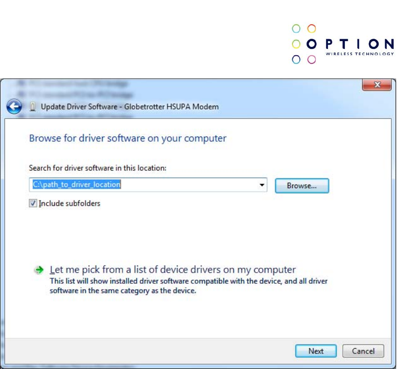
(6) Browse to the location you copied the drivers to and click next.
GTM60x Development Kit
User Guide
Version: v002ext Page: 44 of 112
Option® Copyright: This document may not be duplicated, nor distributed to third parties
without prior and written permission of Option® NV.
Figure 32: Browse for driver software on your computer
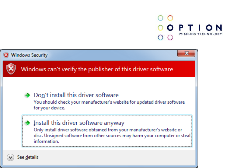
(7) If the drivers are not signed, Windows will request authorization to install
the new drivers. At this moment click on “Install this driver software anyway”.
GTM60x Development Kit
User Guide
Version: v002ext Page: 45 of 112
Option® Copyright: This document may not be duplicated, nor distributed to third parties
without prior and written permission of Option® NV.
Figure 33: Windows Security to install unsigned drivers.
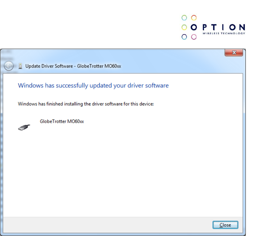
(8) The drivers will be installed. When the installation is finished, click on
close.
GTM60x Development Kit
User Guide
Version: v002ext Page: 46 of 112
Option® Copyright: This document may not be duplicated, nor distributed to third parties
without prior and written permission of Option® NV.
Figure 34: The software for this device has been successfully installed.
(9) Repeat the process starting from 4 to 8 for all other remaining unknown
devices.
GTM60x Development Kit
User Guide
Version: v002ext Page: 47 of 112
Option® Copyright: This document may not be duplicated, nor distributed to third parties
without prior and written permission of Option® NV.
Figure 35: Remaining unknown devices
(10) On successful installation of all drivers, the device manager will show
the following typical installed devices. Please configure the device manager
by selecting “View”, “Devices by connection”. Expand the tree to show the
USB devices (See Figure 26).

GTM60x Development Kit
User Guide
Version: v002ext Page: 48 of 112
Option® Copyright: This document may not be duplicated, nor distributed to third parties
without prior and written permission of Option® NV.
6 FIRMWARE UPGRADE
NOTE: This section describes the upgrade to the latest firmware version of
the GTM60x. At the time of this writing this was version 1.2.0.0. Check with
your Option contact to acquire the latest firmware version.
(1) Copy the latest firmware version to a known location.
(2) Double click the compressed folder to open it.
(3) Extract the two files contained in this compressed folder.
(4) Browse to the folder where you extracted the firmware to.
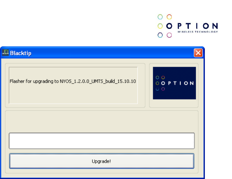
(5) Double click on the executable file
“Blacktip_NYOS_fw_v[new_firmware_version].exe”. A window will open like
in the screenshot below.
GTM60x Development Kit
User Guide
Version: v002ext Page: 49 of 112
Option® Copyright: This document may not be duplicated, nor distributed to third parties
without prior and written permission of Option® NV.
Figure 36: The Blacktip upgrader
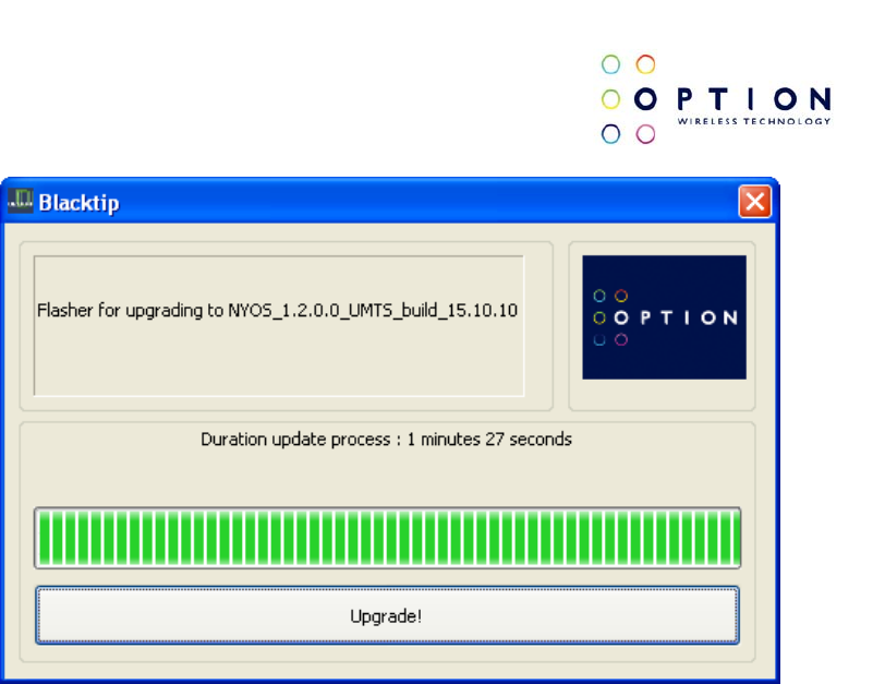
(6) Press the “Upgrade!” button. This process will take a few minutes. Do not
disconnect the device during this time. Wait 10 seconds after the process is
finished before disconnecting the device.
GTM60x Development Kit
User Guide
Version: v002ext Page: 50 of 112
Option® Copyright: This document may not be duplicated, nor distributed to third parties
without prior and written permission of Option® NV.
Figure 37: Module firmware upgrade completed.

GTM60x Development Kit
User Guide
Version: v002ext Page: 51 of 112
Option® Copyright: This document may not be duplicated, nor distributed to third parties
without prior and written permission of Option® NV.
7 HOW TO SEND AT COMMANDS
This section briefly describes how to send AT commands using
HyperTerminal to communicate with the GTM60x.
HyperTerminal is included in Windows XP but not in Windows Vista or
Windows 7. However, it can be downloaded free for personal use from its
creator’s website: http://www.hilgraeve.com/.
This section assumes that Vista and 7 users have downloaded and correctly
installed this program. The instructions on the usage may differ slightly. To
start HyperTerminal, make sure you run it as administrator. You can do this
by right-clicking on the application and selecting “Run as Administrator”.
GTM60x Development Kit
User Guide
Version: v002ext Page: 52 of 112
Option® Copyright: This document may not be duplicated, nor distributed to third parties
without prior and written permission of Option® NV.
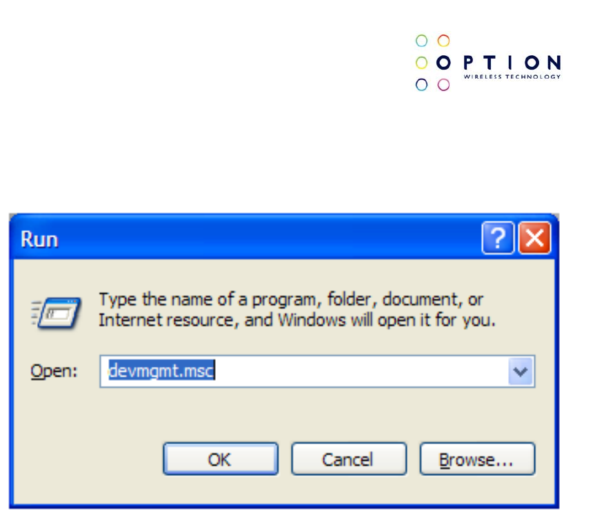
(1) First start device manager. You can do this by going to “Start” menu and
selecting “Run”. Type “devmgmt.msc” in the next dialogue box as displayed
below:
Figure 38: Run device manager
GTM60x Development Kit
User Guide
Version: v002ext Page: 53 of 112
Option® Copyright: This document may not be duplicated, nor distributed to third parties
without prior and written permission of Option® NV.
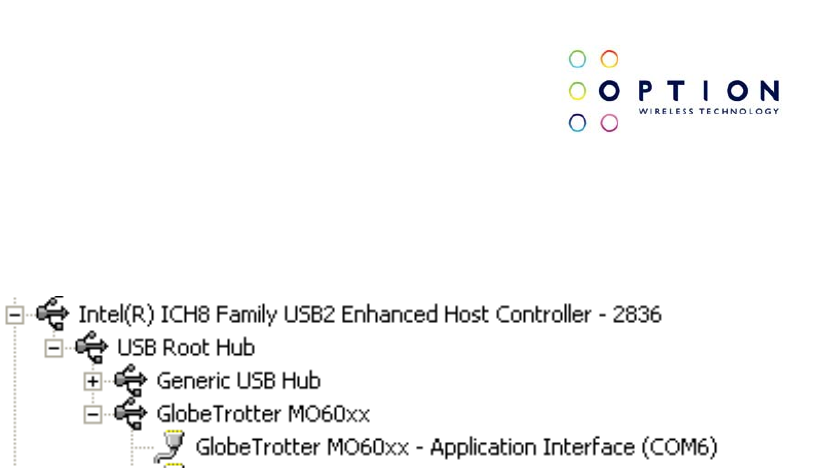
(2) Check the port used by the application interface. In this example, the
application port is COM6. NOTE: In Windows 7 the application interface is
called the Control Interface.
Figure 39: Application interface on COM6.
(3) Open HyperTerminal via the “Start” menu in Windows:
Start All Programs Accessories Communication HyperTerminal
Normally, you only have to perform the following two steps once. If you have
already done this in the past you can skip these steps. If not, pick a country
and an area code of your choice.

GTM60x Development Kit
User Guide
Version: v002ext Page: 54 of 112
Option® Copyright: This document may not be duplicated, nor distributed to third parties
without prior and written permission of Option® NV.
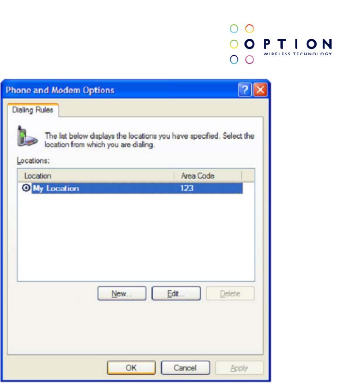
Figure 40: Location information.
(4) Just click “OK” on the “Phone and Modem Options” screen.
GTM60x Development Kit
User Guide
Version: v002ext Page: 55 of 112
Option® Copyright: This document may not be duplicated, nor distributed to third parties
without prior and written permission of Option® NV.
Figure 41: Location information.
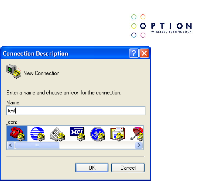
(5) Enter a name for your HyperTerminal connection and press OK.
GTM60x Development Kit
User Guide
Version: v002ext Page: 56 of 112
Option® Copyright: This document may not be duplicated, nor distributed to third parties
without prior and written permission of Option® NV.
Figure 42: Connection Description
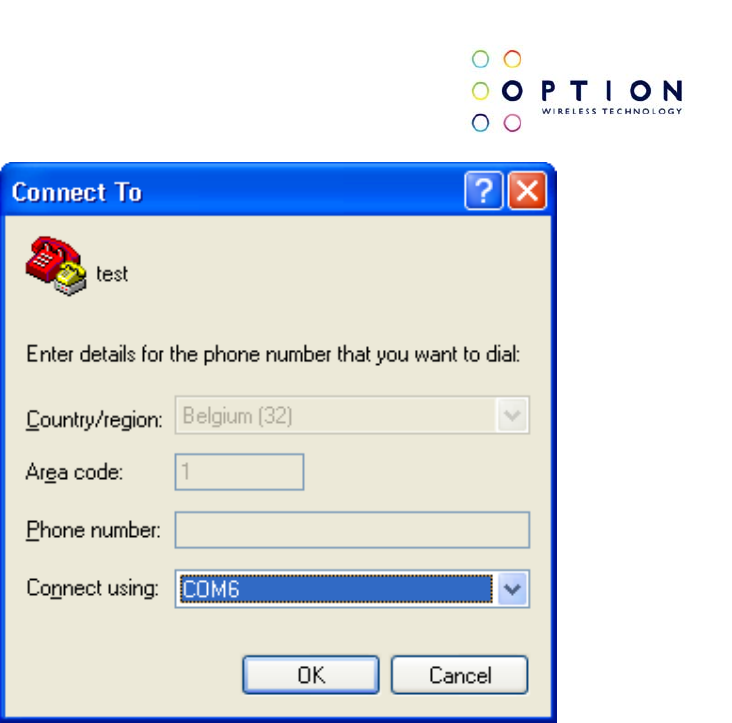
(6) In the next window, change the “Connect using:” field to the application
port you checked under (2). Click OK.
GTM60x Development Kit
User Guide
Version: v002ext Page: 57 of 112
Option® Copyright: This document may not be duplicated, nor distributed to third parties
without prior and written permission of Option® NV.
Figure 43: Connect To
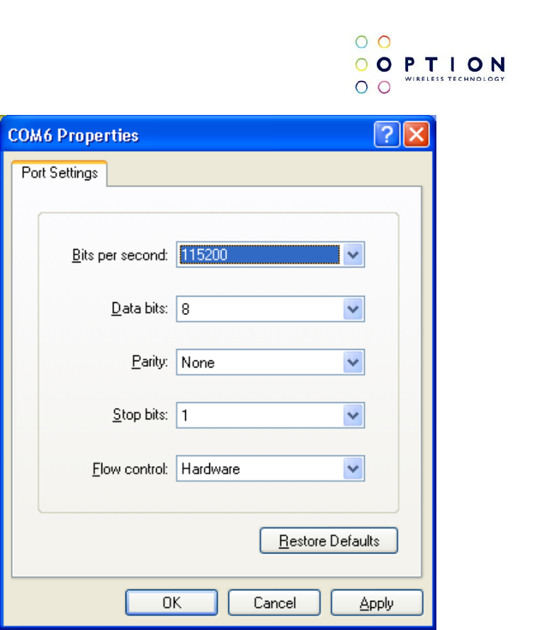
(7) Now the next window will appear. Modify the “Bits per second” field to
115200 and click OK.
GTM60x Development Kit
User Guide
Version: v002ext Page: 58 of 112
Option® Copyright: This document may not be duplicated, nor distributed to third parties
without prior and written permission of Option® NV.
Figure 44: Connection Properties
GTM60x Development Kit
User Guide
Version: v002ext Page: 59 of 112
Option® Copyright: This document may not be duplicated, nor distributed to third parties
without prior and written permission of Option® NV.
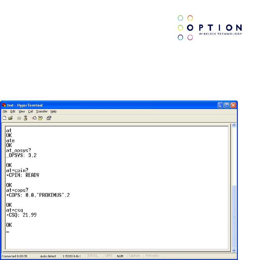
HyperTerminal is now configured and you are ready to issue AT commands
to the module. The figure below shows a typical HyperTerminal session. If
you don’t have visual feedback of what you are typing, you need to turn echo
on by typing ATE, as shown in the example below.
Figure 45: Typical HyperTerminal session

GTM60x Development Kit
User Guide
Version: v002ext Page: 60 of 112
Option® Copyright: This document may not be duplicated, nor distributed to third parties
without prior and written permission of Option® NV.
When you close HyperTerminal, you have the opportunity to save your
HyperTerminal profile. Saved profiles can be found under HyperTerminal in
the “Start” menu.
Start Programs accessories Communication HyperTerminal.

GTM60x Development Kit
User Guide
Version: v002ext Page: 61 of 112
Option® Copyright: This document may not be duplicated, nor distributed to third parties
without prior and written permission of Option® NV.
8 GTM60x CONFIGURATION
Before you set up a data connection, you should configure the module.
Configuring the GTM60x is done by sending AT commands to the application
interface (Windows 7: control interface). You can use HyperTerminal
(explained on the previous section) or another serial communication program
connected to this interface.
This section describes some of the more useful AT commands that can be
sent to the GTM60x. Finally a connection to the internet is made.
8.1 Radio ON/OFF
The GTM60x development kit has a hardware switch to enable or disable the
radio.
You can test if the radio is enabled by using the follwoing AT command:
AT+CFUN?
The expected return should be +CFUN=1 (Radio ON). If the response is
not as expected, check if the radio switch is in the active position. If the
response from the command still is incorrect, type:
AT+CFUN=1

GTM60x Development Kit
User Guide
Version: v002ext Page: 62 of 112
Option® Copyright: This document may not be duplicated, nor distributed to third parties
without prior and written permission of Option® NV.
8.2 RRC security
To be able to register on a real network, security should be set to “Integrity
and ciphering”. This can be done by entering the following AT command:
AT_OSEC=4
To register on a simulator such as an Agilent, security should be set to “Fake
security”. This can be done by entering the following AT command:
AT_OSEC=3
8.3 Preferred system
Make sure the “preferred system” settings are “WCDMA preferred” and
“Acquire both circuit-switched and packet switched systems” by entering:
AT_OPSYS=3,2
8.4 Access Point Name
To set the APN for the Data connection, it is necessary to enter the following
command:
AT+CGDCONT=1,”IP”,"xxx”
In which xxx is the APN provided by your network operator.

GTM60x Development Kit
User Guide
Version: v002ext Page: 63 of 112
Option® Copyright: This document may not be duplicated, nor distributed to third parties
without prior and written permission of Option® NV.
8.5 SIM control
The GTM60x requires a SIM to be fitted in order to access a network (if
working in UMTS mode). Some people use SIMs with PIN code protection.
Some operators mandate the use of PIN codes as this provides protection in
the event of SIM theft.
Before proceeding; the SIM state should be checked:
AT+CPIN?
+CPIN: READY
This means that no pin is required and you can continue:
+CPIN: SIM PIN
This means that a pin number is needed.
If a pin is needed enter it by using the next command:
AT+CPIN=”xxxx”
The “xxxx” field indicates where the 4 digit PIN for the SIM should be entered.
If a PIN hasn’t been defined, the GTM60x will not register until the correct
PIN is entered.

GTM60x Development Kit
User Guide
Version: v002ext Page: 64 of 112
Option® Copyright: This document may not be duplicated, nor distributed to third parties
without prior and written permission of Option® NV.
8.6 Registration
SMS and data connections are only possible if the GTM60x is registered on
a network.
An AT command is use to return the registration state and operator name or
code:
AT+COPS?
+COPS: 0,0,"OPERATOR",2
OK
The “OPERATOR” field indicates the field where the name of your operator
will be written. The number “2” at the end of the response string means you
are registered to the network.
You can now proceed with the next section: Setting up a data call.

GTM60x Development Kit
User Guide
Version: v002ext Page: 65 of 112
Option® Copyright: This document may not be duplicated, nor distributed to third parties
without prior and written permission of Option® NV.
9 SETTING UP A PACKET
SWITCHED DATA CALL
Make sure you have configured the module properly (refer to section 8).
Before attempting the Data connection, ensure you are registered to the
network. Check that the registration LED in Figure 2 is on. Also, the APN for
your operator should be set correctly in the module. This can be done with
the following AT command:
AT+CGDCONT=1,IP,"your APN here”
You have to set this command only once for each module as this setting is
stored in the non-volatile memory of the module. Use the explanation in
section 7 on how to use HyperTerminal to send AT commands.
To verify the APN setting just type: AT+CGDCONT?
9.1 Using Modem interface (Dial-up)
It is possible to set up a data call using Windows RAS dial-up networking.
This section explains how to set up a RAS dial-up connection.
GTM60x Development Kit
User Guide
Version: v002ext Page: 66 of 112
Option® Copyright: This document may not be duplicated, nor distributed to third parties
without prior and written permission of Option® NV.
9.1.1 On Windows XP
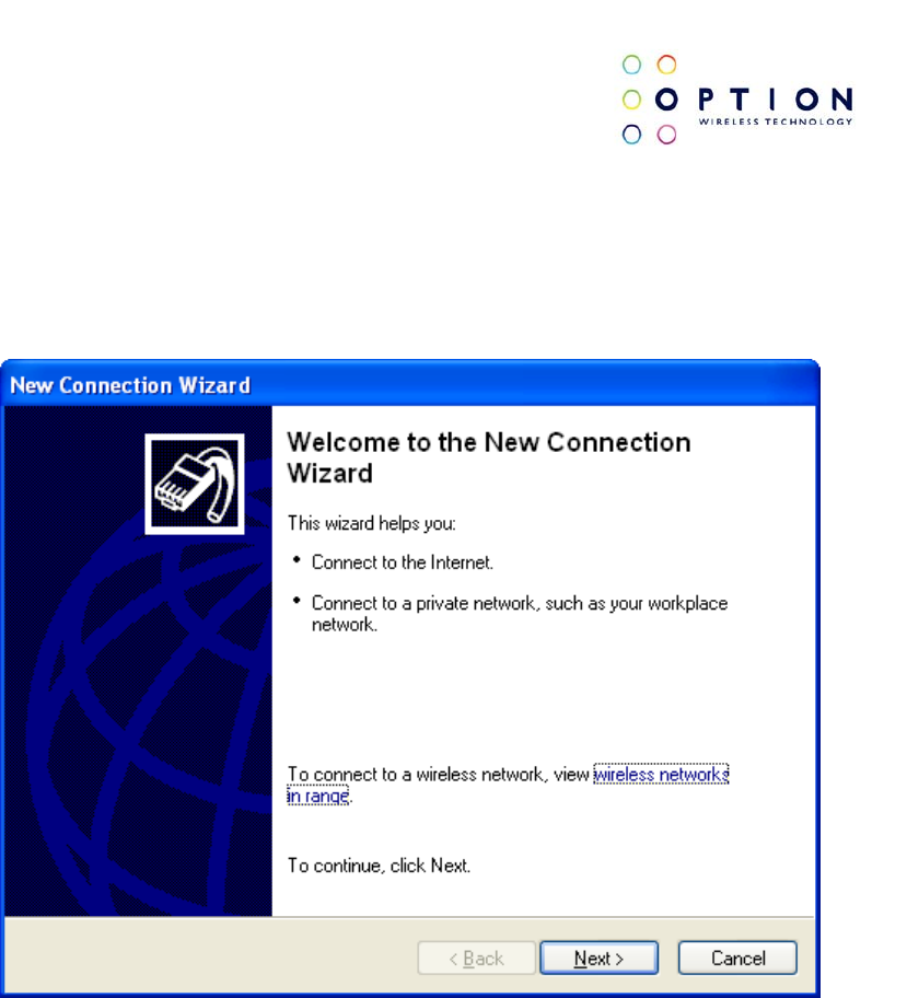
(1) Go to Start → Control Panel→ Network Connections and click on the
icon “New Connection Wizard”. The next screen will appear:
Figure 46: New connection Wizard.
GTM60x Development Kit
User Guide
Version: v002ext Page: 67 of 112
Option® Copyright: This document may not be duplicated, nor distributed to third parties
without prior and written permission of Option® NV.
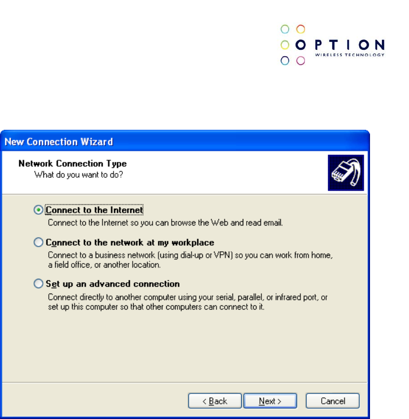
(2) Click “Next” and following figure will appear. Select “Connect to the
Internet” and click “Next” again.
Figure 47: Connect to the Internet.
GTM60x Development Kit
User Guide
Version: v002ext Page: 68 of 112
Option® Copyright: This document may not be duplicated, nor distributed to third parties
without prior and written permission of Option® NV.
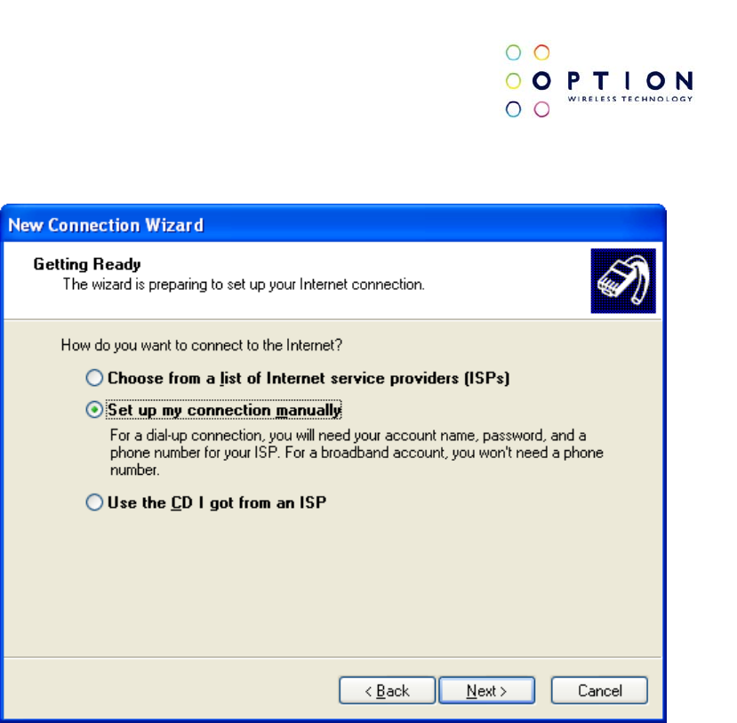
(3) Select “Set up the connection manually”, and click the “Next” button.
Figure 48: Manual connection setup.
GTM60x Development Kit
User Guide
Version: v002ext Page: 69 of 112
Option® Copyright: This document may not be duplicated, nor distributed to third parties
without prior and written permission of Option® NV.
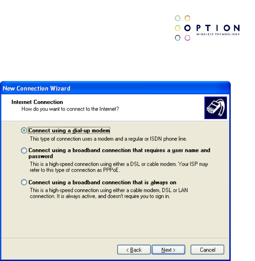
(4) Choose the “Connect using a dial-up modem” option, and click the
“Next” button.
Figure 49: Connection with dial-up modem.
GTM60x Development Kit
User Guide
Version: v002ext Page: 70 of 112
Option® Copyright: This document may not be duplicated, nor distributed to third parties
without prior and written permission of Option® NV.
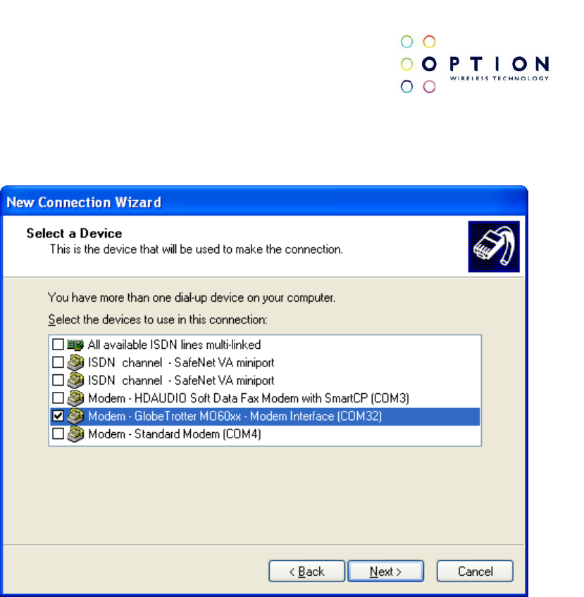
(5) Select the correct RAS modem (Modem - GlobeTrotter MO40X modem
interface), and click the “Next” button.
Figure 50: Select Modem.
GTM60x Development Kit
User Guide
Version: v002ext Page: 71 of 112
Option® Copyright: This document may not be duplicated, nor distributed to third parties
without prior and written permission of Option® NV.
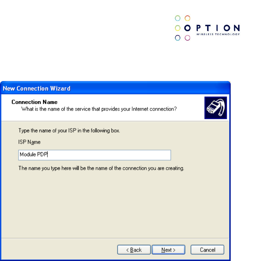
(6) Type a name for the connection that you should select the next time you
need this dial-up connection, and click the “Next” button.
Figure 51: Connection Name.
GTM60x Development Kit
User Guide
Version: v002ext Page: 72 of 112
Option® Copyright: This document may not be duplicated, nor distributed to third parties
without prior and written permission of Option® NV.
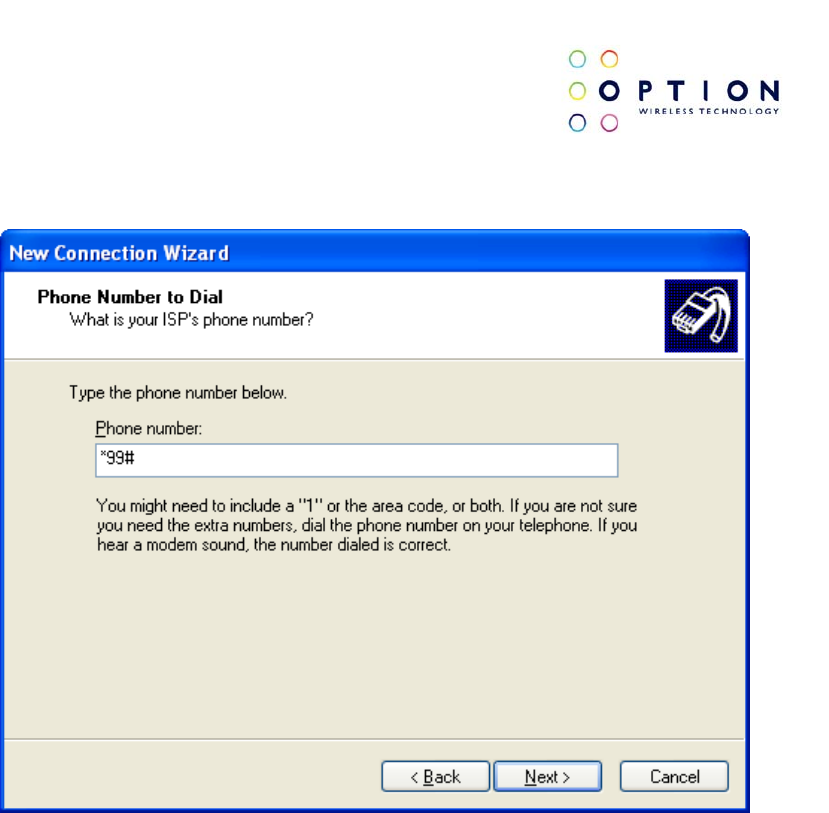
(7) Type in *99# for the telephone number to dial and click the “Next” button.
Figure 52: Number to dial.
GTM60x Development Kit
User Guide
Version: v002ext Page: 73 of 112
Option® Copyright: This document may not be duplicated, nor distributed to third parties
without prior and written permission of Option® NV.
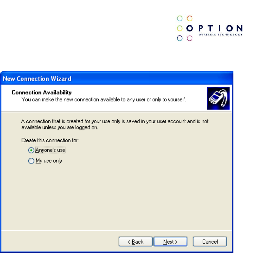
(8) Choose the option you like, and then click the “Next” button.
Figure 53: Connection Availability.
GTM60x Development Kit
User Guide
Version: v002ext Page: 74 of 112
Option® Copyright: This document may not be duplicated, nor distributed to third parties
without prior and written permission of Option® NV.
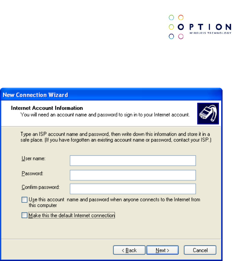
(9) If your service provider requires you to enter your username and
password to set up a PS data call connection, please enter them using the
screen below.
Figure 54: Internet Account Information.
GTM60x Development Kit
User Guide
Version: v002ext Page: 75 of 112
Option® Copyright: This document may not be duplicated, nor distributed to third parties
without prior and written permission of Option® NV.
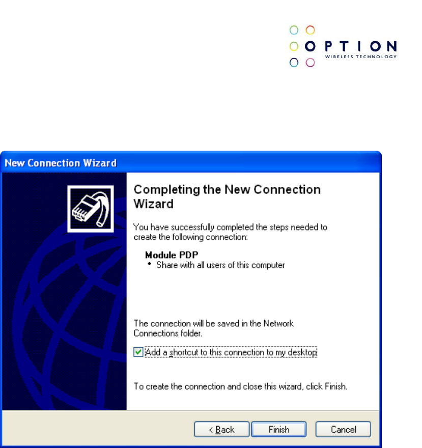
(10) The connection is set up and ready to use. Click the “Finish” button to
close the wizard. This window also offers the possibility to add the
connection into the Desktop by checking the available check box.
Figure 55: Connection complete.
GTM60x Development Kit
User Guide
Version: v002ext Page: 76 of 112
Option® Copyright: This document may not be duplicated, nor distributed to third parties
without prior and written permission of Option® NV.
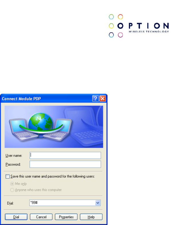
(11) Then, if your module is registered on the network, you can use the
configured dial-up connection to activate a PDP context and make an
Internet connection.
Go to Start→ Connect to→ “Module PDP” and select it.
Figure 56: Connect Module PDP.
GTM60x Development Kit
User Guide
Version: v002ext Page: 77 of 112
Option® Copyright: This document may not be duplicated, nor distributed to third parties
without prior and written permission of Option® NV.
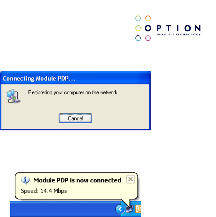
(12) Click the dial button. After a while, a connection to the Internet is made.
Figure 57: Connecting Module PDP.
Figure 58: Module PDP is now connected.
GTM60x Development Kit
User Guide
Version: v002ext Page: 78 of 112
Option® Copyright: This document may not be duplicated, nor distributed to third parties
without prior and written permission of Option® NV.
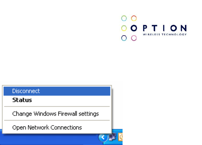
(13) To disconnect, go to the appropriate network systray icon and select
“Disconnect” from the context menu (via right mouse button).
Figure 59: Disconnecting Module PDP.

GTM60x Development Kit
User Guide
Version: v002ext Page: 79 of 112
Option® Copyright: This document may not be duplicated, nor distributed to third parties
without prior and written permission of Option® NV.
9.1.2 On Windows Vista
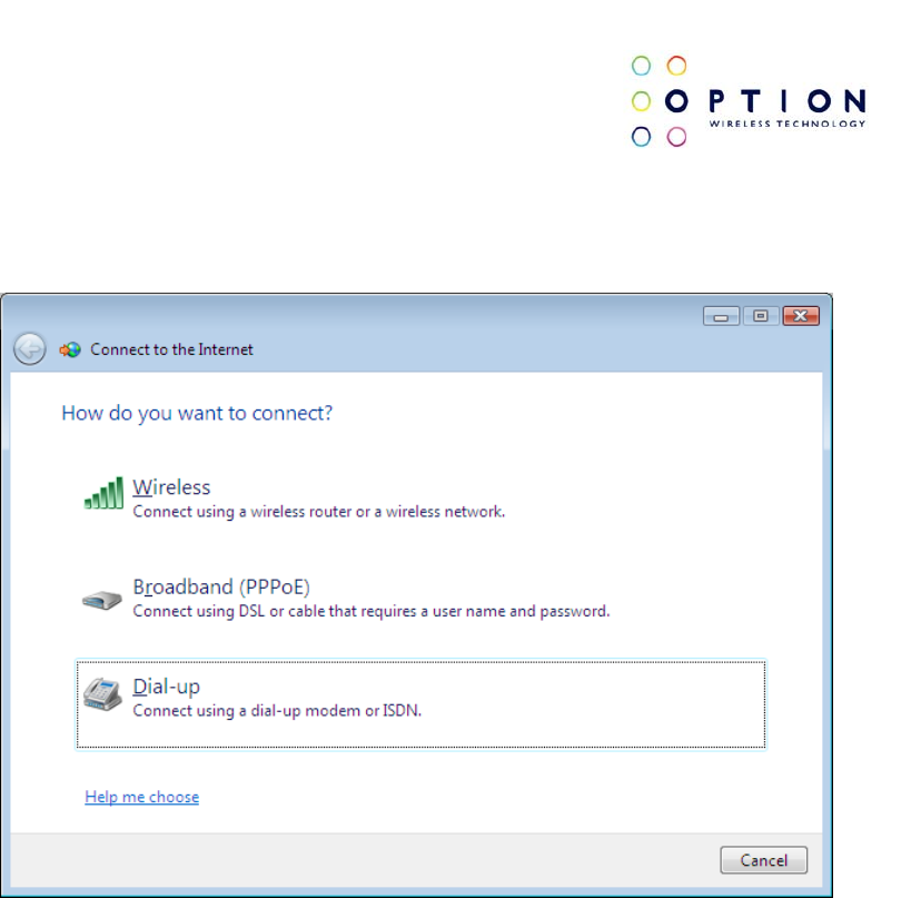
(1) Go to Start→ Control Panel→ Network and Internet check the option
“Connect to the Internet”. Choose Dial-up connection as connection method.
If there is already an existing connection, select “No, create a new
connection” and then choose Dial-up connection as connection method.
Figure 60: Connect to the Internet.
GTM60x Development Kit
User Guide
Version: v002ext Page: 80 of 112
Option® Copyright: This document may not be duplicated, nor distributed to third parties
without prior and written permission of Option® NV.
Figure 61: Select a Dial-up connection.
GTM60x Development Kit
User Guide
Version: v002ext Page: 81 of 112
Option® Copyright: This document may not be duplicated, nor distributed to third parties
without prior and written permission of Option® NV.
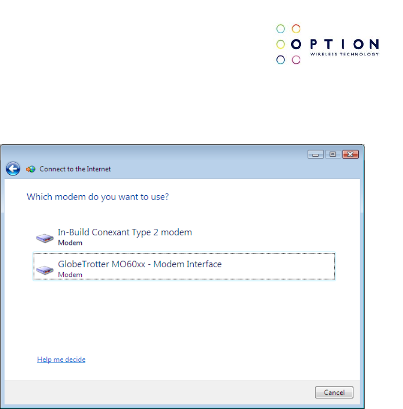
(2) The next dialog will ask for the modem to be use. Select the
GlobeTrotter® modem:
Figure 62: Select the GlobeTrotter® modem.
GTM60x Development Kit
User Guide
Version: v002ext Page: 82 of 112
Option® Copyright: This document may not be duplicated, nor distributed to third parties
without prior and written permission of Option® NV.
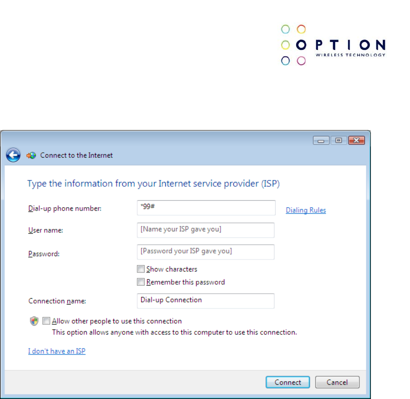
(3) Next, Windows needs your ISP information. Enter the telephone number
*99# and click “Connect”.
Figure 63: Settings for Dial-up connection.
GTM60x Development Kit
User Guide
Version: v002ext Page: 83 of 112
Option® Copyright: This document may not be duplicated, nor distributed to third parties
without prior and written permission of Option® NV.
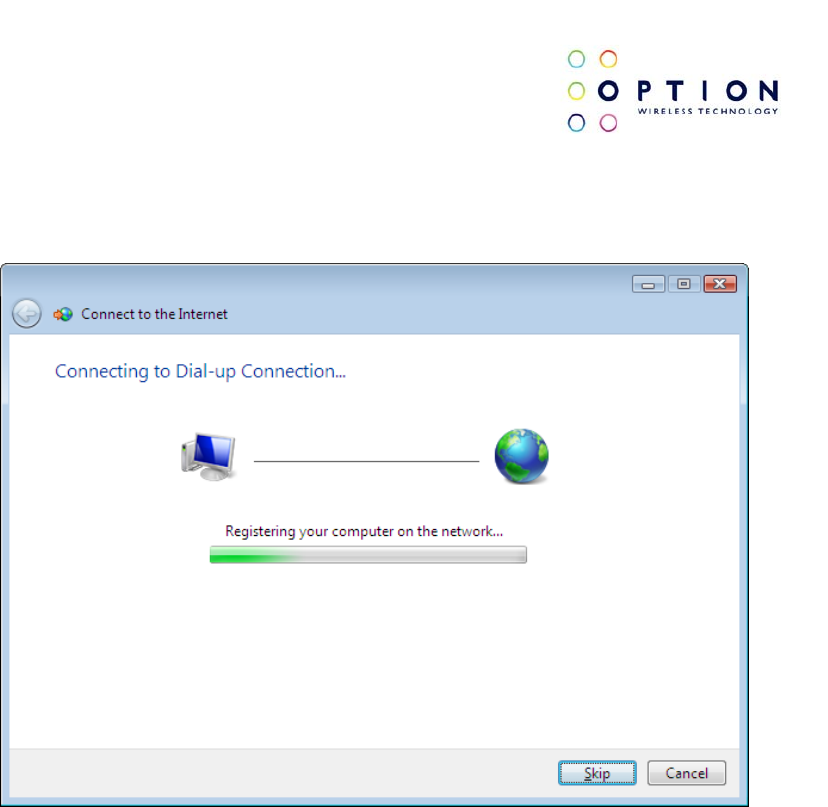
(4) In the following screens, you can monitor the progress as Windows sets
up the connection:
Figure 64: Connecting…
GTM60x Development Kit
User Guide
Version: v002ext Page: 84 of 112
Option® Copyright: This document may not be duplicated, nor distributed to third parties
without prior and written permission of Option® NV.
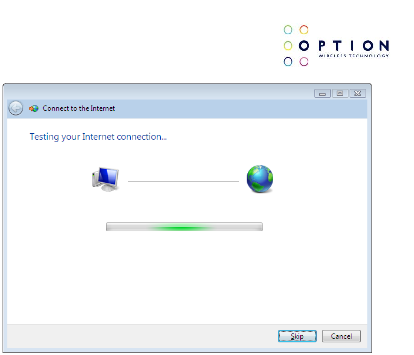
Figure 65: Testing… (This step can be skipped)
GTM60x Development Kit
User Guide
Version: v002ext Page: 85 of 112
Option® Copyright: This document may not be duplicated, nor distributed to third parties
without prior and written permission of Option® NV.
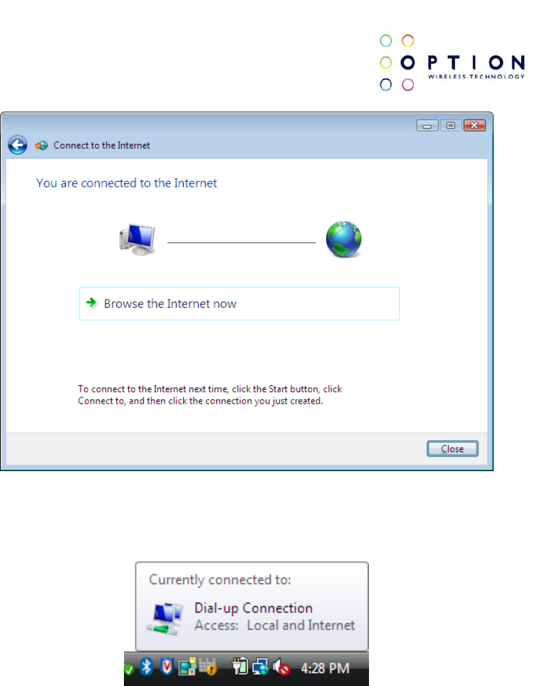
Figure 66: Connected.
Figure 67: Connected.
GTM60x Development Kit
User Guide
Version: v002ext Page: 86 of 112
Option® Copyright: This document may not be duplicated, nor distributed to third parties
without prior and written permission of Option® NV.
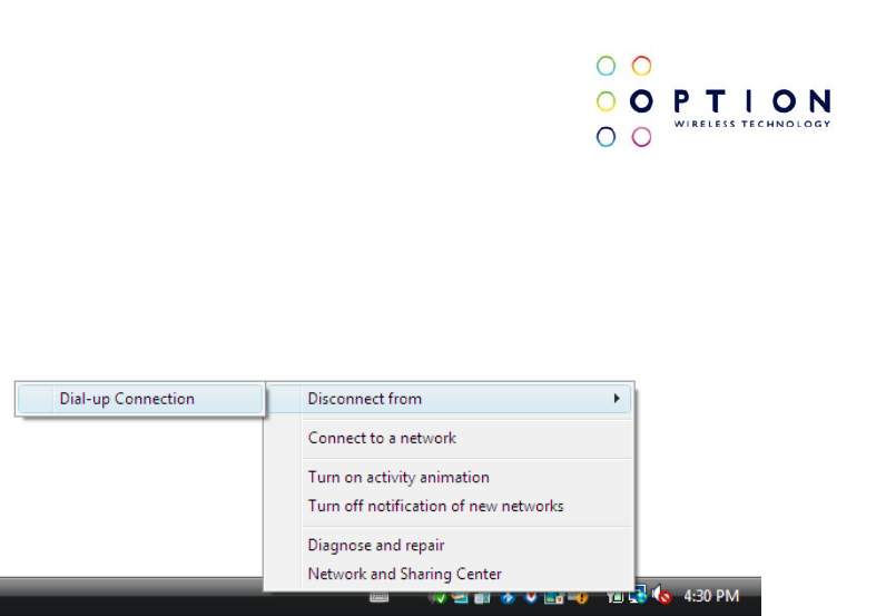
(5) To disconnect, go to the appropriate network systray icon and select
“Disconnect” from the context menu (via right mouse button).
Figure 68: Disconnecting.
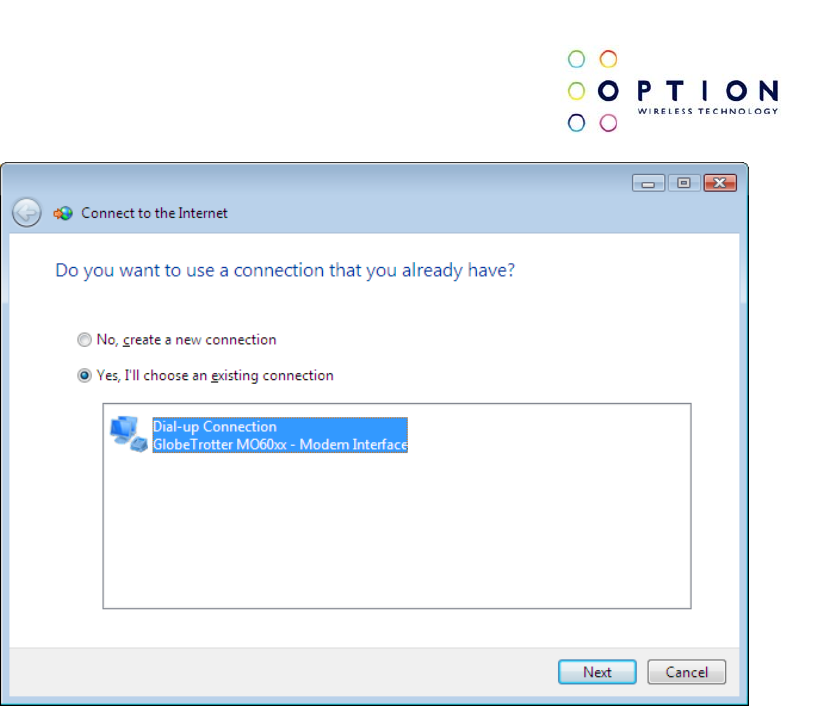
(6) From now on, to redial using the GlobeTrotter®, go back to Start→
Control Panel. Under “Network and Internet”, click the option “Connect to the
Internet”. Windows will show you a list of connections that you have defined
before. Select the one that you have set up in this section.
GTM60x Development Kit
User Guide
Version: v002ext Page: 87 of 112
Option® Copyright: This document may not be duplicated, nor distributed to third parties
without prior and written permission of Option® NV.
Figure 69: Select your connection.
GTM60x Development Kit
User Guide
Version: v002ext Page: 88 of 112
Option® Copyright: This document may not be duplicated, nor distributed to third parties
without prior and written permission of Option® NV.
9.1.3 On Windows 7
To setup a Dial-up connection on windows 7, steps 1 to 4 from section 9.1.2
can be followed.
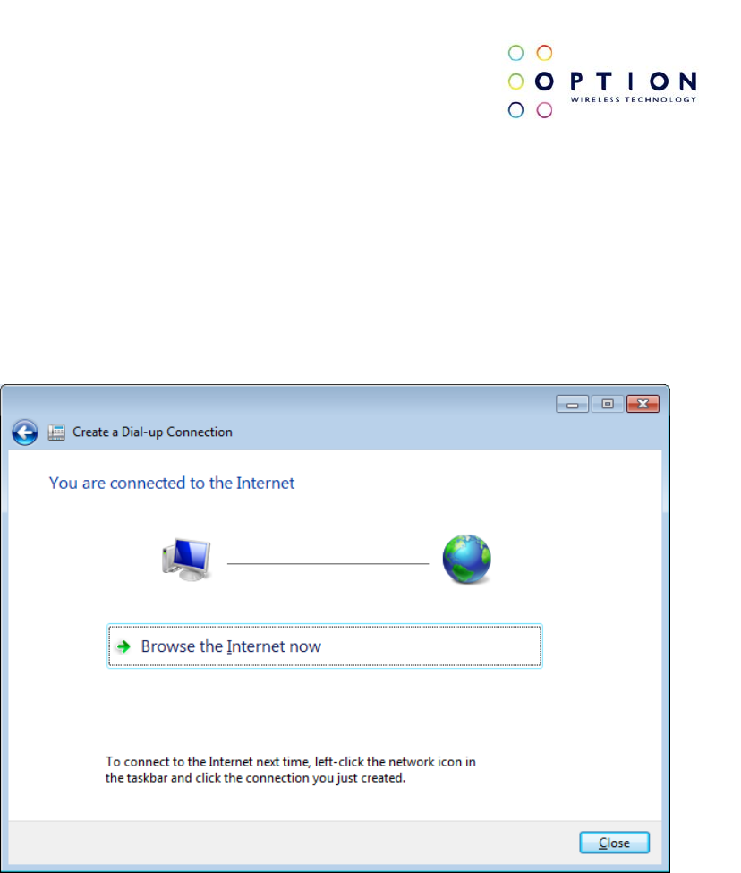
(1) After pressing the connect button on step 3, the device will start the
connection and test it once it is ready.
Figure 70: Connected.
GTM60x Development Kit
User Guide
Version: v002ext Page: 89 of 112
Option® Copyright: This document may not be duplicated, nor distributed to third parties
without prior and written permission of Option® NV.
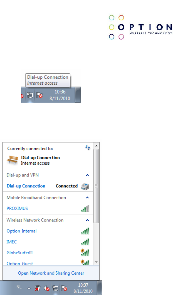
(2) The connection can be also checked on the appropriate network systray
icon:
Figure 71: Connected on systray.
Figure 72: Connected.
GTM60x Development Kit
User Guide
Version: v002ext Page: 90 of 112
Option® Copyright: This document may not be duplicated, nor distributed to third parties
without prior and written permission of Option® NV.
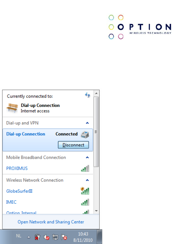
(3) To disconnect, go to the appropriate network systray icon and open the
available connections (via left mouse button). Select the Dial-up connection
and left click on it. Press the “Disconnect” button from menu.
Figure 73: Disconnecting.
GTM60x Development Kit
User Guide
Version: v002ext Page: 91 of 112
Option® Copyright: This document may not be duplicated, nor distributed to third parties
without prior and written permission of Option® NV.
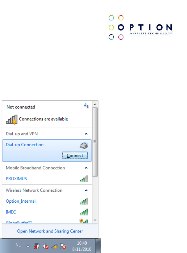
(4) From now on, to redial using the GlobeTrotter®, go to the appropriate
network systray icon and open the available connections (via left mouse
button). Select the Dial-up connection and left click on it. Press the “Connect”
button from menu.
Figure 74: Reconnect using the Dial-up connection.
GTM60x Development Kit
User Guide
Version: v002ext Page: 92 of 112
Option® Copyright: This document may not be duplicated, nor distributed to third parties
without prior and written permission of Option® NV.
9.2 Using NDIS interface
9.2.1 On Windows XP/Vista (Applet)
(1) Locate the executable file: Your Option contact has provided you with a
“.cpl” file. This is the dashboard applet.
(2) Double click on the file appropriate for your operating system. If you have
a 32 bit OS choose the filename ending with 32, if you have a 64 bit OS
choose the filename ending with 64.
Figure 75: Dashboard Applet.
GTM60x Development Kit
User Guide
Version: v002ext Page: 93 of 112
Option® Copyright: This document may not be duplicated, nor distributed to third parties
without prior and written permission of Option® NV.
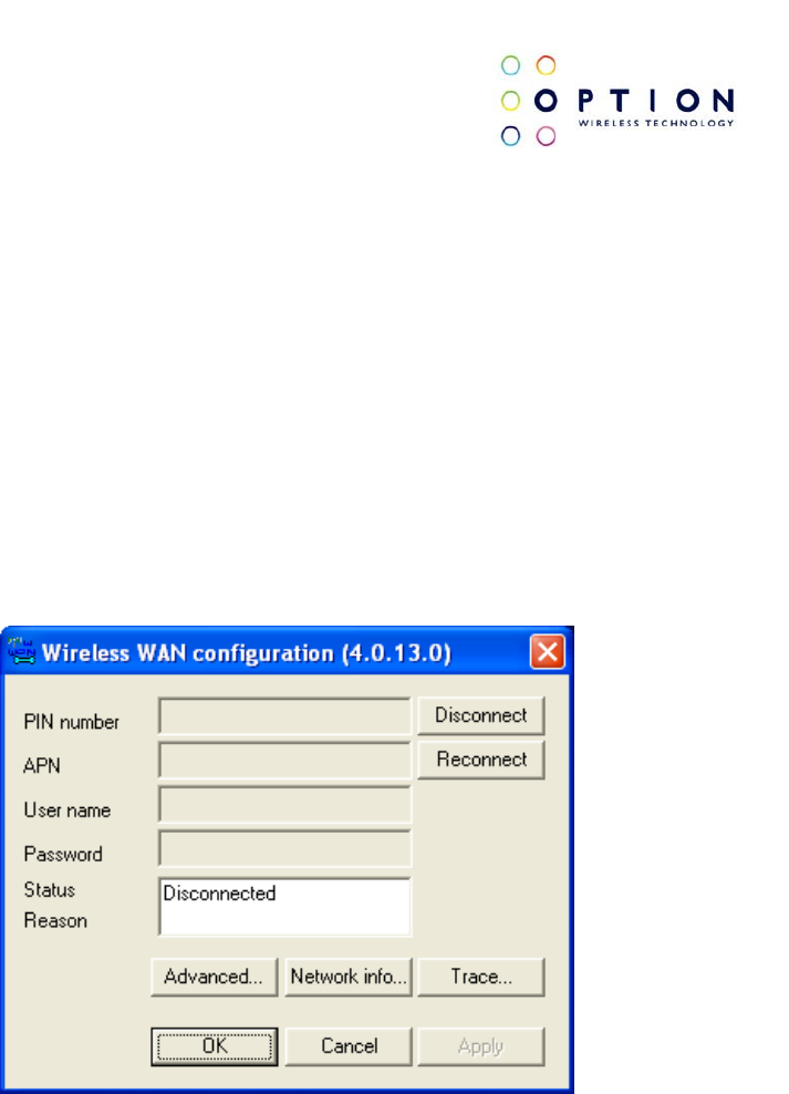
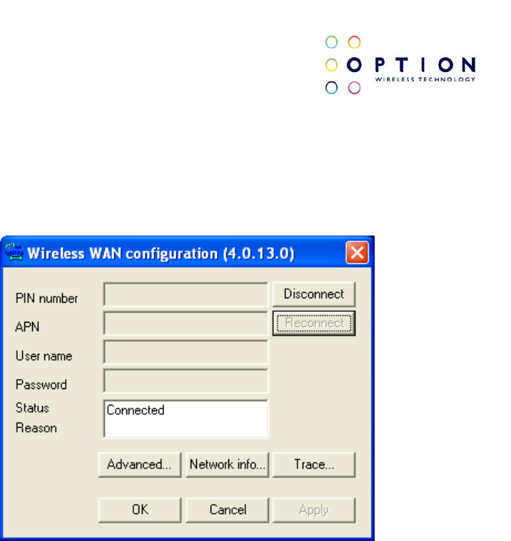
(3) In the Wireless WAN configuration window press on the “Reconnect”
button. When a connection is made the status text field will display
“Connected”.
Figure 76: Connected.
(4) To disconnect, simply press on the “Disconnect” button. When the device
is disconnected the status text field will display “Disconnected”.
GTM60x Development Kit
User Guide
Version: v002ext Page: 94 of 112
Option® Copyright: This document may not be duplicated, nor distributed to third parties
without prior and written permission of Option® NV.
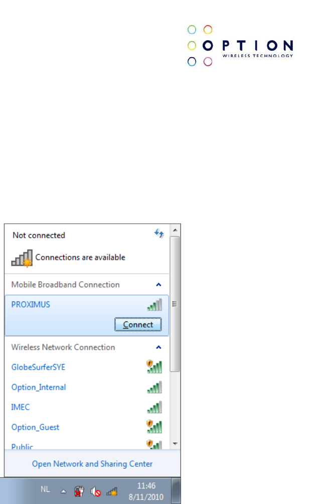
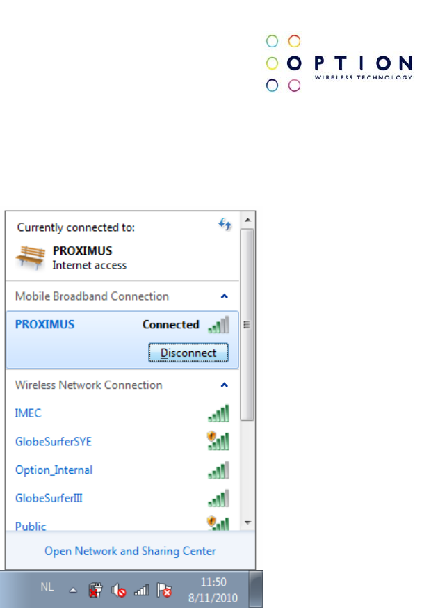
9.2.2 On Windows 7 (Mobile Broadband)
(1) Go to the appropriate network systray icon and open the available
connections (via left mouse button). Select the correct Mobile Broadband
Connection (Service Provider name) and left click on it. Press the “Connect”
button from menu.
Figure 77: Mobile Broadband connection.
GTM60x Development Kit
User Guide
Version: v002ext Page: 95 of 112
Option® Copyright: This document may not be duplicated, nor distributed to third parties
without prior and written permission of Option® NV.
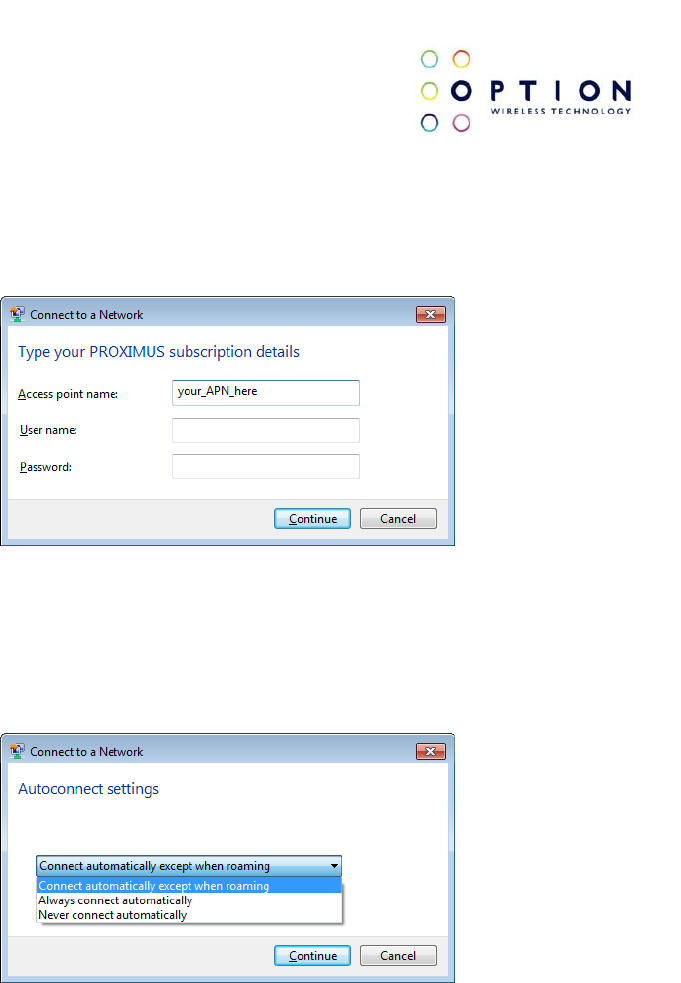
(2) The first time, Mobile Broadband will request the Subscription details to
be use for the new connection. Type your subscription settings here and
press “Continue”.
Figure 78: Subscription settings.
(3) Select an option for the “Autoconnect settings”.
Figure 79: Autoconnect settings.
GTM60x Development Kit
User Guide
Version: v002ext Page: 96 of 112
Option® Copyright: This document may not be duplicated, nor distributed to third parties
without prior and written permission of Option® NV.
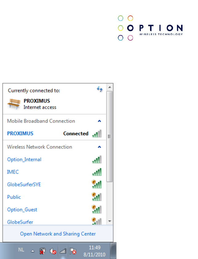
(4) The Internet connection should be active now. The connection status
should be connected.
Figure 80: Active Mobile Broadband connection.
GTM60x Development Kit
User Guide
Version: v002ext Page: 97 of 112
Option® Copyright: This document may not be duplicated, nor distributed to third parties
without prior and written permission of Option® NV.
(5) To disconnect, go to the appropriate network systray icon and open the
available connections (via left mouse button). Select the Mobile Broadband
connection and left click on it. Press the “Disconnect” button from menu.
Figure 81: Disconnecting.

GTM60x Development Kit
User Guide
Version: v002ext Page: 98 of 112
Option® Copyright: This document may not be duplicated, nor distributed to third parties
without prior and written permission of Option® NV.
10 SET UP A GSM/UMTS VOICE
CALL
To be able to make a call, a minimum configuration is needed on the module.
For this, a Terminal connection to the application port is needed. Please,
refer to section 7 for this matter.
(1) First of all, be sure that the device is configured as explained in section 8.
(2) Set switches 1, 2 and 3 to ON state on the Controlling Switch (see
section 8) as shown in the following figure:
Figure 82: Controlling Switch configuration for voice calls.
NOTE: This configuration is applicable on Evaluation Board Revision 1 (EVB
R1). In future Evaluation board, these settings may change.
(3) Enable the circuit switched data transfer on the modem. This setting is
stored in non-volatile memory of the module.

GTM60x Development Kit
User Guide
Version: v002ext Page: 99 of 112
Option® Copyright: This document may not be duplicated, nor distributed to third parties
without prior and written permission of Option® NV.
AT_ODO=0
The response to this AT command should be: OK
(4) By default, the voice part of the firmware is disabled. This setting needs
to be enabled in order to have voice capabilities. This setting is stored in
non-volatile memory of the module.
AT_OPCMENABLE=1
The response to this AT command should be: OK
(5) A PCM audio profile needs to be configured using the following AT
command:
AT_OPCMPROF=<value>
Defined values:
0 Handset
1 Headset
2 Speakerphone
3 Bluetooth Headset
This setting is stored in non-volatile memory of the module.
The response to this AT command should be: OK

GTM60x Development Kit
User Guide
Version: v002ext Page: 100 of 112
Option® Copyright: This document may not be duplicated, nor distributed to third parties
without prior and written permission of Option® NV.
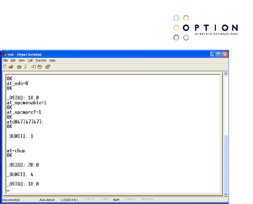
(6) To set up a call, you must use the ATD command followed by a
telephone number.
ATD<phone number>;
NOTE: Do not forget the semicolon (;) at the end of the AT command!
The response to this AT command should be: OK
Attention! You need to plug in the headset in the specified 2,5” audio
connector on the Development kit.
Now the telephone on the other side should answer the paging, and a voice
conversation can be made. To stop the conversation, the other side can
simply hang-up the. If you want to end the call from your side you can type
AT+CHUP (The answer to this command should be OK). The next figure
shows an example voice call setup and termination.
GTM60x Development Kit
User Guide
Version: v002ext Page: 101 of 112
Option® Copyright: This document may not be duplicated, nor distributed to third parties
without prior and written permission of Option® NV.
Figure 83: Voice call example.

GTM60x Development Kit
User Guide
Version: v002ext Page: 102 of 112
Option® Copyright: This document may not be duplicated, nor distributed to third parties
without prior and written permission of Option® NV.
11 GPS FEATURES
11.1 General
The GTM60x module has built-in support for A-GPS (Assisted GPS) and S-
GPS (Standalone GPS) signal processing.
In mobile-assisted GPS (A-GPS) mode, when a request for position location
is issued, available network information is provided to the location server
(e.g., cell-ID) and assistance is requested from the location server. The
location server sends the assistance information to the handset. The
handset/mobile unit measures the GPS observables and provides the GPS
measurements along with available network data (that is appropriate for the
given air interface technology) to the location server. The location server
then calculates the position location and returns results to the requesting
entity.
In standalone (autonomous) GPS mode (S-GPS), the handset demodulates
the data directly from the GPS satellites. This mode has some reduced cold-
start sensitivity, and a longer time to first fix compared to the assisted modes.
However, it requires no server interaction and works out of network coverage.
This combination of GPS measurements and available network information
provides:

GTM60x Development Kit
User Guide
Version: v002ext Page: 103 of 112
Option® Copyright: This document may not be duplicated, nor distributed to third parties
without prior and written permission of Option® NV.
A high-sensitivity solution that works in all terrains: indoor, outdoor,
urban and rural.
High availability that is enabled by using both satellite and network
information.
These two GPS solutions on the module provide optimal time to fix, accuracy,
sensitivity, availability and reduced network utilization in both these
environments, depending on the conditions.
GTM60x Development Kit
User Guide
Version: v002ext Page: 104 of 112
Option® Copyright: This document may not be duplicated, nor distributed to third parties
without prior and written permission of Option® NV.
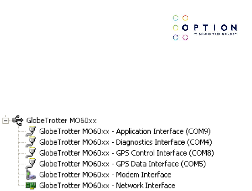
11.2 Set up a GPS connection
The data of the GPS positioning can be monitored from the GPS data
interface. Open the Device Manager and check the Interfaces on the module.
Figure 84: Interfaces on GTM60x
Take note of the GPS data Interface COM port.
Please, refer to your Option point of contact if the GPS interfaces are not
available on your GTM60x.
GTM60x Development Kit
User Guide
Version: v002ext Page: 105 of 112
Option® Copyright: This document may not be duplicated, nor distributed to third parties
without prior and written permission of Option® NV.
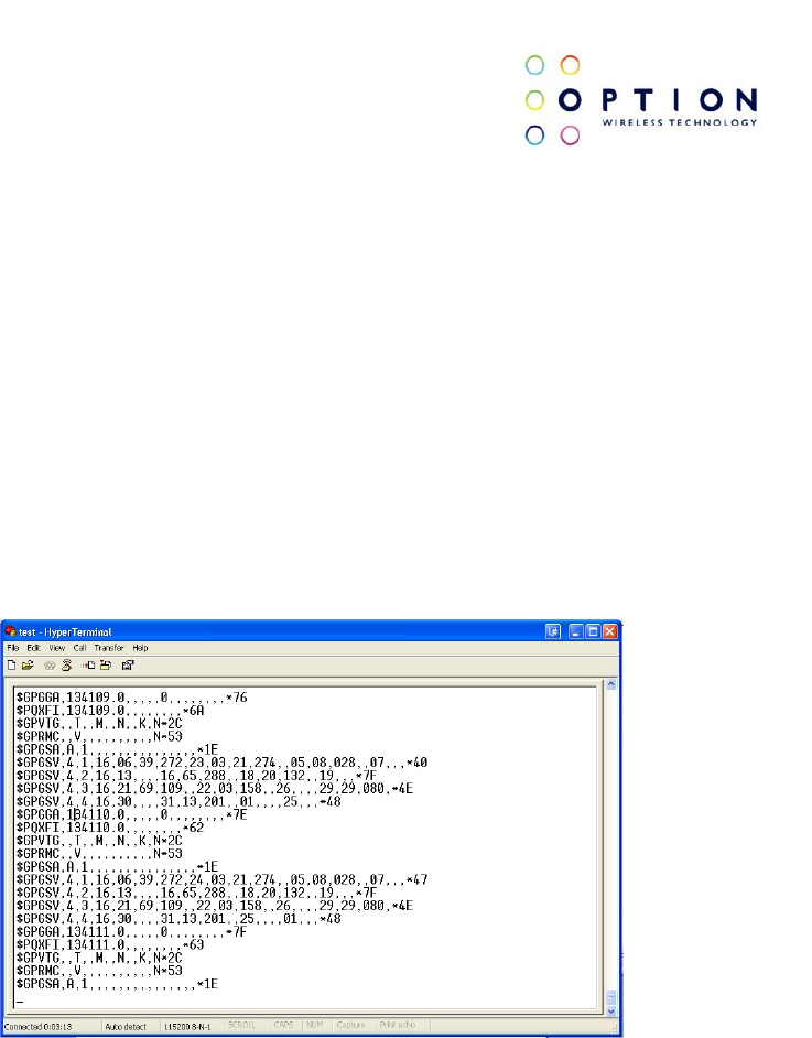
11.2.1 Enabling GPS positioning
By default, GPS positioning is disabled. To enable, connect to the application
port via HyperTerminal and use the command below. The response to this
AT command should be OK.
AT_OGPS=2
The next step is connecting to the GPS Data Interface using HyperTerminal.
Use the COM port you made note on 11.2. This HyperTerminal should
display a series of messages like in the screenshot below.
Figure 85: HyperTerminal connected to GPS data interface
GTM60x Development Kit
User Guide
Version: v002ext Page: 106 of 112
Option® Copyright: This document may not be duplicated, nor distributed to third parties
without prior and written permission of Option® NV.
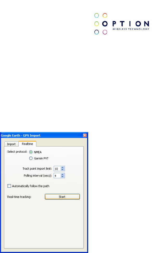
11.2.2 Using the GPS in Google Earth
You can test the GPS by displaying your current position in Google Earth. To
use the GPS in Google Earth the following steps can be used.
(1) Open Google Earth.
(2) Click the
“
Tools
"
dropdown in the menu bar and choose
“
GPS
"
.
Click on the “Realtime” tab and choose “NMEA" as protocol.
Figure 86: Realtime configuration on Google Earth.
GTM60x Development Kit
User Guide
Version: v002ext Page: 107 of 112
Option® Copyright: This document may not be duplicated, nor distributed to third parties
without prior and written permission of Option® NV.
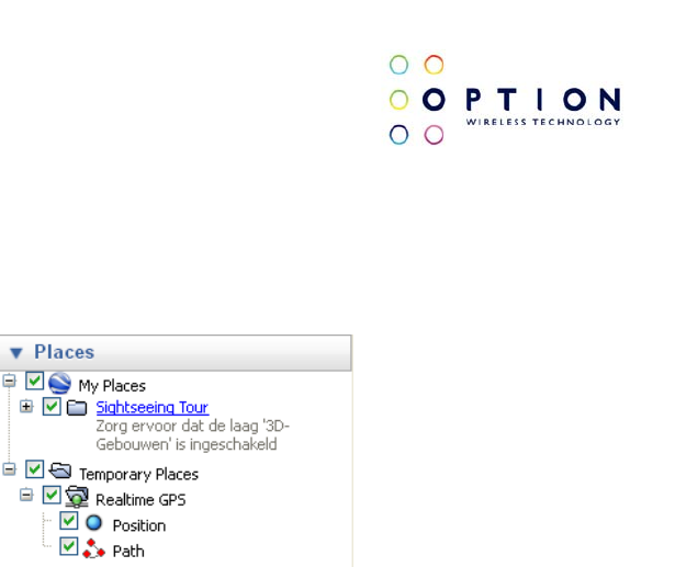
(3) Click
“
Start
"
. Google Earth will now be able to find your location via
GPS. If you want to stop using the GPS, you can click
“
Stop
"
on the
Realtime tab.
Figure 87: Realtime GPS location found
NOTES: Google Earth will need an active internet connection to find the
maps. Google Earth also needs a low COM port number to work.

GTM60x Development Kit
User Guide
Version: v002ext Page: 108 of 112
Option® Copyright: This document may not be duplicated, nor distributed to third parties
without prior and written permission of Option® NV.
REFERENCES
Ref Document
GTM60x Integration Package

GTM60x Development Kit
User Guide
Version: v002ext Page: 109 of 112
Option® Copyright: This document may not be duplicated, nor distributed to third parties
without prior and written permission of Option® NV.
APPENDIX A: LIMITED WARRANTY
HARDWARE: Option® warrants its products to be free from defects in
workmanship and materials, under normal use and service, for one year.
If a product does not operate as warranted during the applicable warranty
period, Option® shall, at its option and expense, repair the defective
product or part, deliver to Customer an equivalent product or part to
replace the defective item. All products replaced will become property of
Option®. Replacement products may be new or reconditioned. Option®
shall not be responsible for any software, firmware, information or
memory data of Customer contained in, stored on, or integrated with any
products returned to Option® pursuant to any warranty.
SOFTWARE: Option® warrants that the software programs licensed from
it will perform in substantial conformance to the program specifications
therefore for a period of ninety (90) days from the date of purchase from
Option® or its Authorized Reseller. Option® warrants the magnetic media
containing software against failure during the warranty period. No updates
are provided. Option®’s sole responsibility hereunder shall be (at
Option®’s discretion) to replace any defective media with software, which
substantially conforms to Option®’s applicable published specifications.
Customer assumes responsibility for the selection of the appropriate
applications program and associated reference materials. Option® makes

GTM60x Development Kit
User Guide
Version: v002ext Page: 110 of 112
Option® Copyright: This document may not be duplicated, nor distributed to third parties
without prior and written permission of Option® NV.
no warranty that its products will work in combination with any hardware
or applications software products provided by third parties, that the
operation of the software products will be uninterrupted or error-free, or
that all defects in the products will be corrected. For any third-party
products listed in the Option® software product documentation or
specifications as being compatible, Option® will make reasonable efforts
to provide compatibility, except where the non-compatibility is caused by
a “bug” or defect in the third party’s product.
STANDARD WARRANTY SERVICE: Standard warranty service for
hardware products may be obtained by delivering the defective product,
accompanied by a copy of the dated proof a purchase, to Option®’s
Corporate Service Centre or to an Authorized Option® Reseller during the
applicable warranty period. Standard warranty service for software
products may be obtained by calling Option®’s Corporate Service Centre
or an Authorized Reseller, within the warranty period. Products returned
to Option®’ Corporate Service Centre must be pre-authorized by Option®
with a Return Material Authorization (RMA) number marked on the
outside of the package, and sent prepared, insured, and packaged
appropriately for safe shipment. The repaired or replaced item will be
shipped to Customer, at his own expense, not later than thirty (30) days
after receipt by Option®.

GTM60x Development Kit
User Guide
Version: v002ext Page: 111 of 112
Option® Copyright: This document may not be duplicated, nor distributed to third parties
without prior and written permission of Option® NV.
WARRANTIES EXCLUSIVE: If an Option® product does not operate as
warranted above, customer’s sole remedy shall be repair or replacement,
at Option®’s option. The foregoing warranties and remedies are exclusive
and are in lieu of all other warranties, express or implied, either in fact or
by operation of law, statutory or otherwise, including warranties of
merchantability and fitness for a particular purpose, Option® neither
assumes nor authorizes any person to assume for it any other liability in
connection with the sale, installation, maintenance or use of its products.
Option® shall not be liable under this warranty if its testing and
examination disclose that the alleged defect in the product does not exist
or was caused by Customer’s or any third person’s misuse, neglect,
improper installation or testing, unauthorized attempts to repair, or any
other cause beyond the range of intended use, or by accident, fire or
other hazard.
LIMITATION OF LIABILITY: In no event, whether based in contract or
tort (including negligence) shall Option® be liable for incidental,
consequential, indirect, special or punitive damages of any kind, or for
loss of revenue, loss of business, or other financial loss arising out of or in
connection with the sale, installation, maintenance, use, performance,
failure, or interruption of its products, even if Option® or its Authorized
Reseller has been advised of the possibility of such damages.

GTM60x Development Kit
User Guide
Option NV – Gaston Geenslaan 14 – 3001 Leuven Belgium
T +32 16 317 411 – F +32 16 207 164
www.option.com
Copyright ©2010 OPTION. All rights reserved. Option, GlobeTrotter and the
Option logo are registered trademarks of OPTION. All third-party trademarks
are the property of their respective owners.
Option® Copyright: This document may not be duplicated, nor distributed to
third parties without prior and written permission of Option® NV.

GTM609W
FCC-ID: NCMOMO6092
IC: 2734A-MO6092
Certification Leaflet
AGENCY REQUIREMENTS
Licensed by QUALCOMM Incorporated under one or more of the following United States Patents and/or their counterparts
in other nations: 4,901,307; 5,490,165; 5,056,109; 5,504,773; 5,101,501; 5,506,865; 5,109,390; 5,511,073; 5,228,054;
5,535,239; 5,267,261; 5,544,196; 5,267,262; 5,568,483; 5,337,338; 5,600,754; 5,414,796; 5,657,420; 5,416,797;
5,659,569; 5,710,784; 5,778,338
Federal communications commission notice
This equipment has been tested and found to comply with the limits for a Class B digital device, pursuant to Part 15 of the
FCC Rules. These limits are designed to provide reasonable protection against harmful interference in a residential
installation. This equipment generates, uses, and can radiate radio frequency energy and, if not installed and used in
accordance with the instructions, may cause harmful interference to radio communications. However, there is no
guarantee that interference will not occur in a particular installation. If this equipment does cause harmful interference to
radio or television reception, which can be determined by turning the equipment off and on, the user is encouraged to try
to correct the interference by one or more of the following measures:
> Reorient or relocate the receiving antenna.
> Increase the separation between the equipment and receiver.
> Connect the equipment into an outlet on a circuit different from that to which the receiver is connected.
> Consult the dealer or an experienced radio or television technician for help.
Modifications
The FCC requires the user to be notified that any changes or modifications made to this device that are not expressly
approved by Option could void the user's authority to operate the equipment.
This device complies with Part 15 of the FCC rules.
This device complies with Part 15 of the FCC rules. Operation is subject to the following two conditions:
(1) this device may not cause harmful interference, and
(2) this device must accept any interference received, including interference that may cause undesired operation.
Avis de conformité aux normes d’Industrie Canada.
Cet appareil numérique de classe B est conforme aux normes canadiennes ICES-003 et RSS-210.
Son fonctionnement est soumis aux deux conditions suivantes:
(1) cet appareil ne doit pas causer d'interférence et
(2) cet appareil doit accepter toute interférence, notamment les interférences qui peuvent affecter son fonctionnement.
Exposure Information to Radio Frequency Energy
Users concerned with the risk of Radio Frequency exposure may wish to limit the duration of their calls and to position the
antenna as far away from the body as is practical.
Informations concernant l'exposition aux fréquences radio (RF)
La puissance de sortie émise par l’appareil de sans fil Dell est inférieure à la limite d'exposition aux fréquences radio
d'Industry Canada (IC). Utilisez l’appareil de sans fil Dell de façon à minimiser les contacts humains lors du
fonctionnement normal.
Ce périphérique a été évalué et démontré conforme aux limites SAR (Specific Absorption Rate – Taux d'absorption
spécifique) d'IC lorsqu'il est installé dans des produits hôtes particuliers qui fonctionnent dans des conditions d'exposition
à des appareils portables (les antennes se situent à moins de 20 centimètres du corps d'une personne).
Ce périphérique est homologué pour l'utilisation au Canada. Pour consulter l'entrée correspondant à l’appareil dans la
liste d'équipement radio.
Modular approval
The module can be integrated into fixed or mobile categorized end-products, so that 20 cm separation distance to end-
user can be assured. You can integrate the module in a portable device, in this case a permissive change application
would be required.
Approbation par module
Le module peut être incorporé à un produit final classé comme fixe ou mobile, mais d’une manière à garantir que l’usager
final soit à une distance de 20 cm. Vous pouvez incorporer le module à un appareil portable, et dans ce cas, une
demande de changement autorisée serait requise.
Device marking
The integrated device must carry the CE mark and Notified body number of the Notified Body used in the Annex IV
conformity assessment of the module on the manufacturing label as described in the R&TTE directive 1999/5/EC Annex
VII. This Notified Body approval only applies to the module and not the final integrated product. The final integrated
product should undergo its own conformity process to the R&TTE directive and should meet all applicable CE marking
directives in order to place the CE mark on the final integrated product.
described in FCC Part 2.925 and 2.926.
Industry Canada requires the host device to be marked with “Contains transmitter module IC: 2734A-MO6092” conform to
section 3.2.1 from the RSS-GEN guidelines.
Marquage du dispositif
Le dispositif incorporé doit porter la marque CE et le numéro de l’organisme notifié utilisé dans l’Annexe IV de l’évaluation
de la conformité du module, sur l’étiquette de fabrication, tel que décrit dans l’Annexe VII portant sur les équipements
radio et équipements terminaux de télécommunication (« R&TTE »). Cette approbation de l’organisme notifié ne
s’applique qu’au module et non au produit final après intégration. Le produit final après intégration devrait être lui-même
l’objet d’un processus d’évaluation de la conformité à la directive sur les équipements radio et équipements terminaux de
télécommunication et devrait suivre toutes les directives applicables relatives au marquage CE pour placer la marque CE
sur le produit final après intégration.
Le dispositif fini doit aussi être marqué, de la manière appropriée, avec l’identification du FCC,
dispositif hôte soit marqué sous la forme « Contains transmitter module IC: 2734A-MO6092 » conformément à la section
3.2.1 des directives CNR-Gen.
Manufacturer's Disclaimer Statement
The information in this document is subject to change without notice and does not represent a commitment on the part of
the vendor. No warranty or representation, either expressed or implied, is made with respect to the quality, accuracy, or
fitness for any particular purpose of this document. The manufacturer reserves the right to make changes to the content of
this document and/or the products associated with it at any time without obligation to notify any person or organization of
such changes. In no event will the manufacturer be liable for direct, indirect, special, incidental, or consequential damages
arising out of the use or inability to use this product or documentation, even if advised of the possibility of such damages.
For questions regarding your product or declaration, contact:
Option | Gaston Geenslaan 14 | 3001 Leuven | Belgium | www.option.com
SYSTEM REQUIREMENTS
> Must be supplied by a SELV (Safety Extra Low Voltage) circuit with limited power.
European Union declaration of conformity
This products bears the CE marking and complies with the R&TTE Directive (1999/5/EC), EMC Directive (89/336/EEC)
and the Low Voltage Directive (73/23/EEC) issued by the Commission of the European Community.
Compliance with these directives implies conformity to the following European Norms:
Radio Frequency spectrum efficiency:
> EN 301 511, v9.0.2
> EN 301 908-1, v4.2.1
> EN 301 908-2, v4.2.1
Electromagnetic Compatibility
> EN 301 489-1, v1.8.1: 2008
> EN 301 489-3, v1.4.1: 2002
> EN 301 489-7, v1.3.1: 2005
Safety and Health
> EN 60950-1: 2006 +A11: 2009
This product may be used in the following countries:
> All EU Memberstates
> Iceland
> Switzerland
> Norway
> United States of America
For questions regarding your product or FCC declaration, contact:
Option | Gaston Geenslaan 14 | 3001 Leuven | Belgium | www.option.com
To identify this product we refer to the Part, Series, or Model number found on the product.
The end device must also be appropriately marked with the FCC identification, “Contains FCC ID: NCMOMO6092”, as
“Contains FCC ID:
NCMOMO6092”
, tel que décrit dans « FCC Part 2.925 » et 2.926. Industrie Canada exige que le
> EN 300 440-2, v1.4.1: 2010
> EN 301 489-24, v1.5.1: 2010