Orion Electric Co 5Q740 15 Inch Color Digital Monitor User Manual for 5Q740 15 Inch Color Digital Monitor
Orion Electric Co Ltd 15 Inch Color Digital Monitor Users Manual for 5Q740 15 Inch Color Digital Monitor
Users Manual for 5Q740 15 Inch Color Digital Monitor
USER’S MANUAL
MODEL No.: 5Q740
BEFORE USING THIS COLOR MONITOR,
READ AND OBSERVE ALL OF THIS USER’S MANUAL
1
CONTENTS
SAFETY INSTRUCTION 2
CAUTIONS 4
FCC RF INTERFERENCE STATEMENT 5
INSTALLATION 6
RESOLUTION 7
CONTROLS AND FUNCTIONS 8
REAR VIEW 13
SPECIFICATIONS 14
TROUBLE SHOOTING GUIDE 15
This Monitor was
Manufactured by ISO 9001
Certified Factory

SAFETY INSTRUCTION
1.Read all of these instructions.
2.Save these instructions for later use.
3.Follow all warnings and instructions marked on the product.
4.Unplug this product from the wall outlet before cleaning.
Do not use liquid cleaners or aerosol cleaners. Use a dry cloth for cleaning.
5.Do not use this product near water.
6.Do not place this product on an unstable cart, stand or table.
The product may fall, causing serious damage to the product.
7.Slots and openings in the cabinet and the back or bottom are provided for
ventilation: to ensure reliable operation of the product and to protect it from
overheating these openings must not be blocked by placing the product on a bed,
sofa, rug or other similar surface. This product should never be placed near or over
a heat register.
This product should not be placed in a built-in installation unless proper ventilation
is provided.
8.This product should be operated from the type of power source indicated on the
marking label. If you are not sure of the type of power available consult your dealer
or local power company.
9.This product is equipped with a 3 wire grounding type plug having a third(grounding)
pin. This is a safety feature. If you are unable to insert the plug into the outlet,
contact your electrician to replace your obsolete outlet. Do not defeat the purpose of
the grounding-type plug.
10.Do not allow anything to rest on the power cord.
Do not locate this product where persons will walk on the cord.
11.If an extension cord is used with this product, make sure that the total of the
ampere ratings on the products plugged into the extension cord do not exceed the
extension cord ampere rating. Also, make sure that the total of all products
plugged into the wall outlet does not exceed 10 amperes.
12.Never push objects of any kind into this product through cabinet slots as they may
touch dangerous voltage points or short out parts that could result in a risk of fire
or electric shock. Never spill any kind of liquid on the product.
3¶INSTRUCTION MANUAL
SAFETY INSTRUCTION
13. Do not attempt to service this product yourself, as opening or removing covers
may expose you to dangerous voltage points or other risks.
Refer all servicing to service personnel.
14. Unplug this product from the wall outlet and refer servicing to qualified service
personnel under the following conditions.
A. When the power cord or plug is damaged or frayed.
B. If liquid has been spilled into the product.
C. If the product has been exposed to rain or water.
D. If the Product does not operate normally when the operating instructions are
followed. Adjust only those controls that are covered by the operating
instructions since improper adjustment of other controls may result in damage
and will often require extensive work by a qualified technician to restore normal
operation.
E. If the product has been dropped or the cabinet has been damaged.
F. If the product exhibits a distinct change in performance, indicating a need for
service.
CCAAUUTTIIOONN
The power supply cord is used as the main disconnect device, ensure that the
socket-outlet is located/installed near the equipment and is easily accessible.
AATTTTEENNTTIIOONN
Le cordon d`alimentation est utillsé comme interrupteur général. La prise de
courant doit être située ou installée à proximité du matériel et être facile
d`accès
CAUTION TO SERVICE PERSONNEL
POWER SUPPLY CORD IS USED AS MAIN POWER DISCONNECT DEVICE IN
THIS PRODUCT. UNPLUG THIS PRODUCT FROM THE WALL OUTLET
BEFORE REMOVING THE BACK COVER AND SERVICING
EMISSION CHARACTERISTICS TESTED BY SEMKO
THIS PRODUCT HAS BEEN TESTED AND HAS SHOWN COMPLIANCE WITH
THE NATIONAL SPECIFICATIONS SUCH AS SWEDISH MPR 1990.10.(MPR•±)
4
CAUTIONS
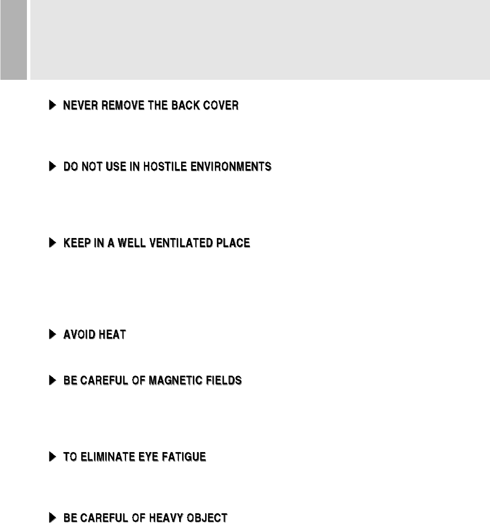
Removal of the back cover should be carried out only by qualified personnel.
This display monitor contains high voltage inside.
To prevent shock or fire hazard. Do not expose the unit to rain or moisture.
This unit is designed to be used in the office or home. Do not subject the unit to
vibrations, dust of corrosive gases.
Ventilation holes are provided on the cabinet to prevent the temperature from
rising.
Do not cover the unit or place anything on the top of unit. Ventilation holes are
provided also on the bottom of the cabinet.
Avoid placing the unit in direct sunshine or near a heating appliance.
Do not place a magnet, speaker system, floppy disc drive or anything which will
generate magnetism near the unit, A magnetic field may cause blurred colors or
distortion of the displayed pattern.
Do not use the unit against a bright back ground and where sunlight or other light
sources will shine directly on the monitor.
Neither the monitor itself nor any other heavy object should rest on the power cord.
Damage to a power cord can cause fire or electrical shock.

5
FCC RF
INTERFERENCE STATEMENT
NNOOTTEE ::
This equipment has been tested and found to comply with the limits for a
Class B digital device, pursuant to Part 15 of the FCC Rules. These limits are
designed to provide reasonable protection against harmful interference in a
residential installation.
This equipment generates, uses and can radiate radio frequency energy and,
if not installed and used in accordance with the instructions, may cause
harmful interference to radio communications. However, there is no guarantee
that interference will not occur in a particular installation.
If this equipment does cause harmful interference to radio or television
reception which can be determined by turning the equipment off and on, the user
is encouraged to try to correct the interference by one or more of the following
measures.
- Reorient or relocate the receiving antenna.
- Increase the separation between the equipment and receiver.
- Connect the equipment into an outlet on a circuit different from that to which
the receiver is connected.
- Consult the dealer or an experienced radio, TV technician for help.
- Only shielded interface cable should be used.
Finally, any changes or modifications to the equipment by the user not
expressly approved by the grantee or manufacturer could void the users
authority to operate such equipment.
¢∫DOC COMPLIANCE NOTICE
This digital apparatus does not exceed the Class B limits for radio noise emissions
from digital apparatus set out in the radio interference regulation of Canadian
Department of Communications.
¢∫AVIS DE CONFORMATION AU MDC(DOC)
Le présent appareil numérique n´émet pas de bruits radio-électriques dépassant les
limites appliqués aux appareils numériques de Class B d´après les règlements sur
le brouillage radio-électrique conçuent par le ministère des communications du
Canada.
¶ 6
INSTALLATION
NO TOOLS ARE REQUIRED TO INSTALL THE MONITOR.
SIMPLY FOLLOW THE INSTRUCTIONS OUTLINED IN THE
FOLLOWING PAGE.
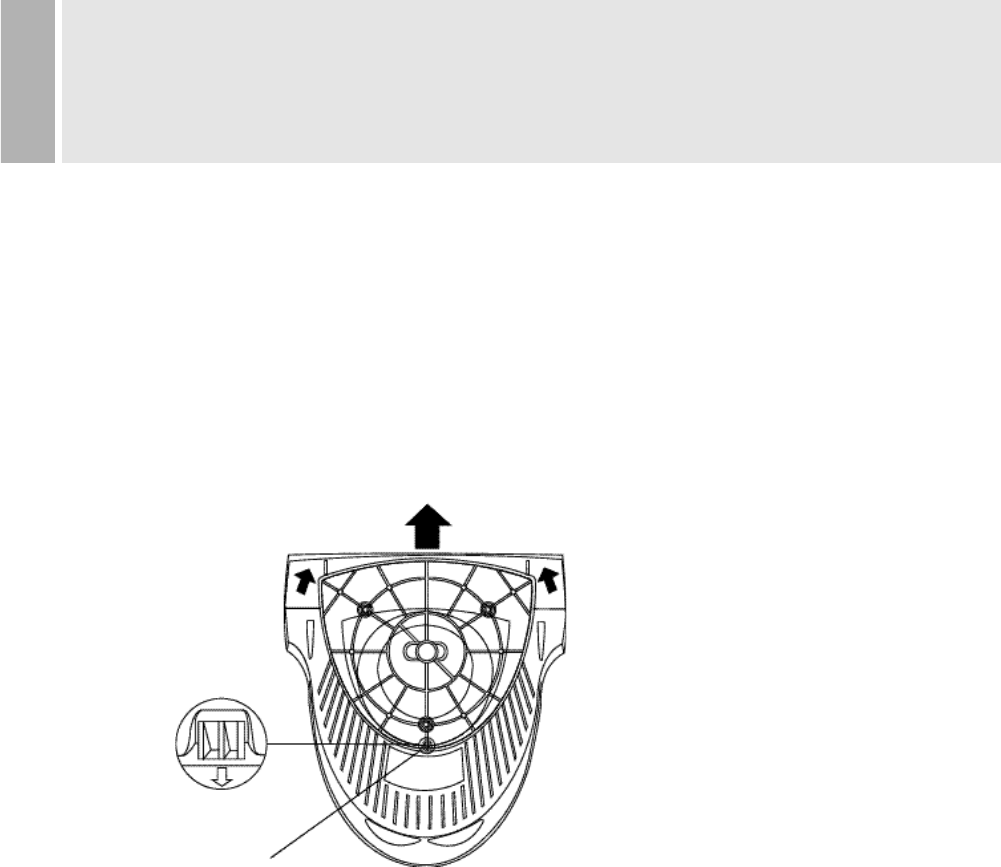
1. INSTALLING THE TILT/SWIVEL STAND
1) Align the stand with the slots in the bottom of the monitor and insert the
Tilt/Swivel Stand into the slots.
2) Push the Tilt/Swivel Stand firmly toward the front of the monitor until the latches
click into the locked position.
2. CONNECT THE SIGNAL CABLE
1) Connect the end into the graphic card on back of the computer.
2) Secure the connection with the screws on the plug.
3. CONNECT THE POWER CORD
Connect the female end of the power cord to the power input
receptacle on the back panel of the monitor.
Then, plug the male end of the power cord to an AC outlet or computer.
4. TURN THIS MONITOR ON AND START YOUR SYSTEM
HOOK
b
1
2 2
a
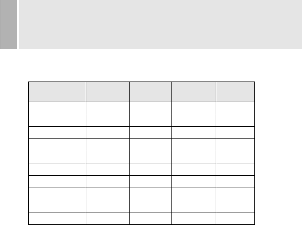
Resolution Horizontal Vertical Clock Poles
Frequency(KHz) Frequency(Hz) Frequency(MHz) (H / V)
IBM(640 * 350)
IBM(720 * 400)
IBM(640 * 480)
VESA(640 * 480)
VESA(800 * 600)
VESA(800 * 600)
VESA(800 * 600)
VESA(1024 * 768)
VESA(1024 * 768)
VESA(1280 * 1024)
31.469
31.469
31.469
43.269
37.879
46.875
53.674
48.363
68.677
63.981
70.087
70.087
59.941
85.008
60.317
75.000
85.061
60.004
84.997
60.020
25.175
28.322
25.175
36.000
40.000
49.500
56.256
65.000
94.500
108.000
(+ / -)
(- / +)
(- / -)
(- / -)
(+ / +)
(+ / +)
(+ / +)
(- / -)
(+ / +)
(+ / +)
7
RESOLUTION
It has 10 user setting modes which you can store except for factory setting mode.
Displaying user mode except for factory setting modes, please adjust the monitor
screen for yourself.
After that, the screen data is stored to the memory within microprocessor.
2. THE WAY OF ADJUSTMENT
When you want to adjust the screen, please refer to function of controls.
Those screen data are automatically stored to the memory within microprocessor.
1. RECOMMENDED SIGNAL TIMING CHART
¶8
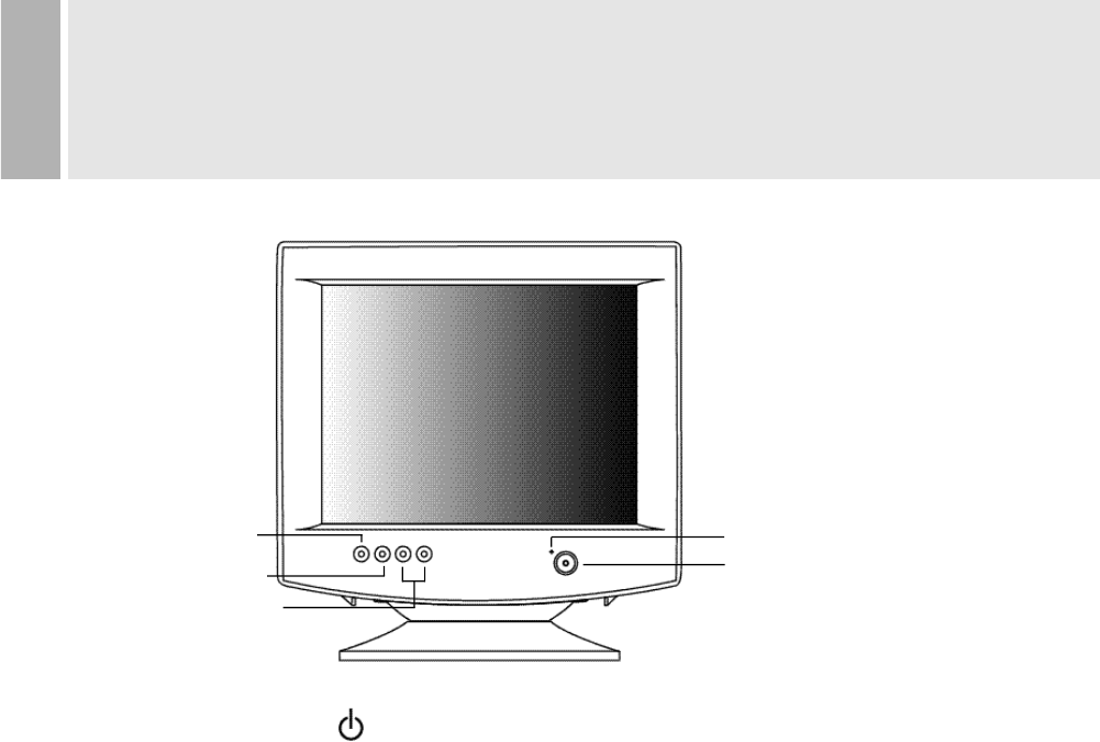
CONTROLS AND FUNCTIONS
A. POWER SWITCH( )
Turns the power ON or OFF. There will be a few seconds delay before
the display appears.
The power LED(next to the power switch) lights when the power
is turned ON.
The power is turned off by pressing the power switch again and
the power LED goes out.
B. DEGAUSS BUTTON
If the CRT of the monitor becomes magnetized, Picture color is not clean and
may be in different light and darkness.
If you push the DEGAUSS botton when OSDmenu is not shown, you can get
the clean picture and uniformity color.
But, if you push the DEGAUSS button when OSD menu is shown, you make
OSD menu disappeared.
In addition, you can use this button to return to the previous menu after adjustment.
NOTE
- The CRT is degaussed automatically each time the monitor is turned on.
- When the button is pushed, the picture will be oscillate for a few seconds.
- Pressing more than once has on effect.
If you want to demagnetize again, push after at least 30 minutes.
C.SELECT BUTTON
POWER INDICATOR(LED)
A. POWER SWITCH
D. ADJUST BUTTONS
(DOWN & UP)
B.DEGAUSS BUTTON
9¶INSTRUCTION MANUAL
CONTROLS AND FUNCTIONS
You can use the UP or DOWN button to make selection for each function.
If you push this SELECT button once more, this allows you to activate the desired
adjustment with the change of adjustment bar color black to violet.
C. SELECT BUTTON
If you want to adjust to the monitor, push the SELECT button.
If you push the button, one of the following two OSD menu is displayed for
control on screen.
¶10
CONTROLS AND FUNCTIONS
NO SIGNAL
CHECK SIGNAL CABLE
D. ADJUST(up & down)
The Adjust button allows user to choose the icons (controls) in the menu.
Pressing the adjust button up or down will step through all available
adjustment icons (controls).
In addition this adjust button can be used to adjust the icons (controls)
that is selected and activated via the select button.
Press the Adjust button.
A window containing an adjustment bar will increase or decrease.
After completing all the desired adjustments, the On Screen Display
will disappear with pressing the degauss button.
1. SELF-TEST DISPLAY
When there is no signal input (No connection), the On Screen Display
will show.
2. AUTO REGISTRATION
This monitor has 10 preset modes. If the current video is one of the preset modes,
the monitor keeps storing the custom display settings into the permanent memory.
There are also 10 user modes that allow you to save the custom display settings
made to any video mode that is not one of the preset modes.
Adjustments are automatically registered without pressing any buttons.
Up to 10 user modes are stored automatically on a “First-In-First-Out” basis.
11
CONTROLS AND FUNCTIONS
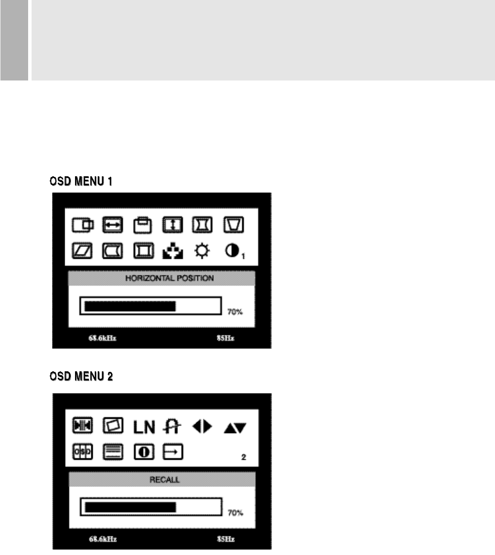
3. OSD MENU DESCRIPTION
OSD MENU 1
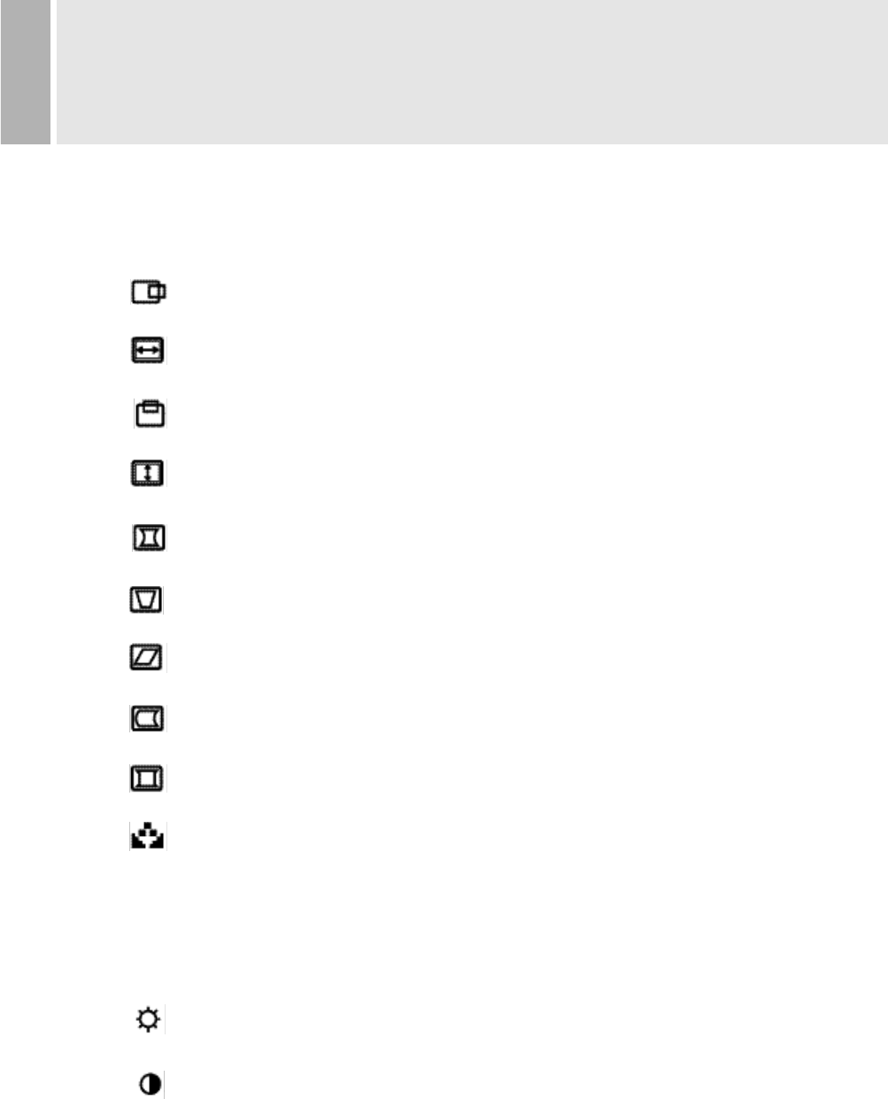
H POSITION (Horizontal Position)
Moves images horizontally on screen left(up
) or right(down„).
H SIZE (Horizontal Size)
Increases(up„) or decreases(down  ) size of image horizontally
V POSITION (Vertical position)
Moves images vertically on screen up or down.
V SIZE (Vertical Size)
Increases(up„) or decreases(down) size of image vertically
PINCUSHION
Adjusts the side Pin-cushion or barrelling.
TRAPEZOID
Adjusts the display sides to be parallel.
PARALLELOGRAM
Adjusts the tilt of the display sides.
PIN BALANCE
Adjusts the curvature of the left and right sides of the screen image.
CORNER CORRECTION
Adjusts the top and bottom corners of the Screen image.
COLOR TEMPERATURE
Adjusts color temperature to 9300K, 6500K(notes : 9300K is factory default).
Or, for a custom color mode, select “USER” and push the select button to
activate the RGB Sub-menu.
This adjusts the intensity of the RGB video output. Using the select button
activate the RG(Red Gain), GG(Green Gain) or BG(Blue Gain) and change
color strength for a customized color mode.
BRIGHTNESS
Increases(up„) or decreases( Â down) the intensity(illumination) of the image.
CONTRAST
Increases(up„) or decreases(down  ) the strength(lightness or dimness of the
image.
¶12
OSD MENU 2
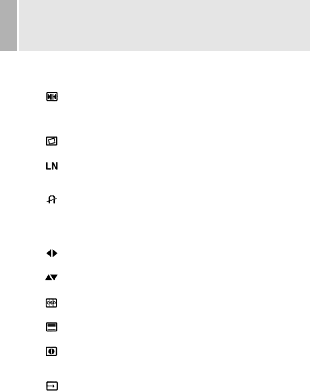
RECALL
Resets the control functions back to the original factory preset values.
In order for the Recall function to work, the timing must fall under one of the
factory preset timing modes.
ROTATION
Adjusts the tilt of image.
LANGUAGE
Selects a language among ENGLISH, DEUTSCH, FRANÇAIS, ESPAÑOL,
ITALIANO, JAPANESE.
DEGAUSS
Manually demagnetizes the CDT. This can be used if the display becomes
discolored.
Allow a minimum of 5 minutes to elapse between each degauss.
The monitor also will automatically degauss when power is applied.
OSD HORIZONTAL
Moves the OSD position to left or right.
OSD VERTICAL
Moves the OSD position to up or down
OSD ON TIME
Adjusts on screen OSD running time.
MOIRE
Adjusts the moire level of the screen.
INFORMATION
Displays horizontal frequency and vertical frequency and
“PRESET MODE” means the factory preset mode.
EXIT
Exits the OSD menu.
CONTROLS AND FUNCTIONS
13
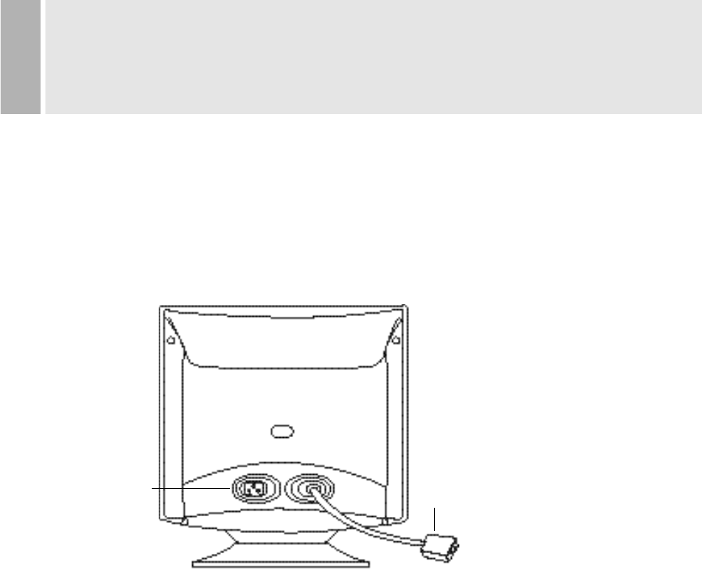
REAR VIEW
E.AC INLET
Power cord connection.
NOTE
Power cord is used as main power disconnect device in this product.
F. D-SUB CONNECTOR OF SIGNAL CABLE
Connect to the analog RGB signal output connector of video card.
ACCESSORY
1. POWER CORD
2. INSTRUCTION MANUAL
E. AC INLET F.D-SUB CONNECTOR
OF SIGNAL CABLE
¶14
15inch Dynamic focus
90°£Deflection
0.28mm Dot Pitch
1280x1024 Non Interlaced @60Hz
HORIZONTAL: 30-70KHz
VERTICAL : 50-150Hz
VIDEO:Analog (0.7Vp-p) 75
SYNC:Horizontal(4.0 Vp-p), Vertical(4.0 Vp-p)
Preset: 265mm X 195mm
Full : 282mm X 212mm
487mm X 463mm X 447mm (Carton Box)
Net Weight : 12.0Kg
Gross Weight : 14.0Kg
AC100 - 240V, 50/60Hz (auto switching)
75W(Power Saving: Less Than 5W)
Technical specifications are subject to change without notice.
SPECIFICATIONS
15
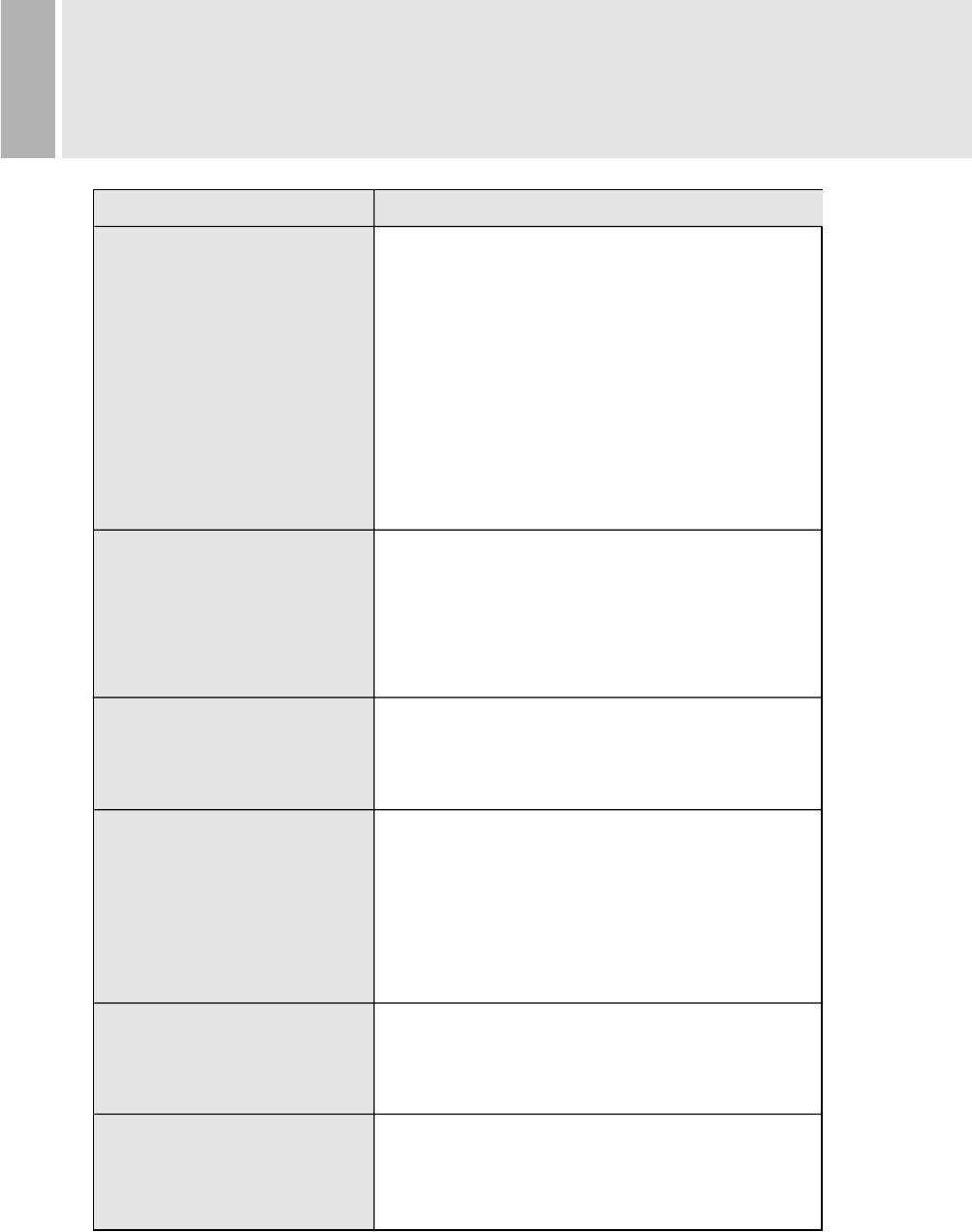
TROUBLE SHOOTING GUIDE
1.Check that power cord of the Monitor have
been connected securely into wall outlet
or grounded extension cable or strip.
2.Power switch should be in the ON position
and LED is lit.
3.Check that the Brightness and/or the Contrast
adjustments of the Display have not been
turned down to minimum levels.
1.The signal cable should be completely
connected to the video card/computer.
2.The video card should be completely seated in
its slot and the computer is switched ON.
Adjust size and position in the OSD, your settings
will be memorized automatically in microprocessor
of the monitor.
The sound you hear indicates that the demagnet-
izing circuit is activated.
Every time the monitor is powered on, it will go
through the degaussing process which helps
eliminate any purity problems.
Remove electric equipments that may be causing
electric intereference to the monitor.
This usually occurs if an extension signal cable
is installed or the signal cable is not
fastened to the back of the video card.
TROUBLE TROUBLE SHOOTING TIP
No image on display screen
“No signal, Check signal
Cable” message on screen
Display image is not
centered, too small or
too large
“Humming” sound when
switching on the monitor
Picture bounces or a
wave pattern is present in
the picture
There appears to be a
second image or “ghost” on
the screen