Orion Electric Co F7T765 17 Inches Color Monitor User Manual
Orion Electric Co Ltd 17 Inches Color Monitor
User Manual
1 INSTRUCTION MANUAL
CONTENTS
SAFETY INSTRUCTION 2
CAUTIONS 4
FCC RF INTERFERENCE STATEMENT 5
INSTALLATION 6
RESOLUTION 7
CONTROLS AND FUNCTIONS 8
REAR VIEW 13
SPECIFICATIONS 14
TROUBLE SHOOTING GUIDE 15
WICHTIGE HINWEISE (GERMAN) 16
This Monitor was
Manufactured by ISO 9001
Certified Factory

INSTRUCTION MANUAL 2
SAFETY INSTRUCTION
1. Read all of these instructions.
2. Save these instructions for later use.
3. Follow all warnings and instructions marked on the product.
4. Unplug this product from the wall outlet before cleaning.
Do not use liquid cleaners or aerosol cleaners. Use a dry cloth for cleaning.
5. Do not use this product near water.
6. Do not place this product on an unstable cart, stand or table.
The product may fall, causing serious damage to the product.
7. Slots and openings in the cabinet and the back or bottom are provided for
ventilation: to ensure reliable operation of the product and to protect it from
overheating these openings must not be blocked by placing the product on a bed,
sofa, rug or other similar surface. This product should not be placed near or over
a heat register.
This product should not be placed in a built-in installation unless proper ventilation
is provided.
8. This product should be operated from the type of power source indicated on the
marking label. If you are not sure of the type of power available, consult your dealer
or local power company.
9. This product is equipped with a 3 wire grounding type plug having a third(grounding)
pin. This is a safety feature. If you are unable to insert the plug into the outlet,
contact your electrician to replace your obsolete outlet. Do not defeat the purpose of
the grounding-type plug.
10. Do not allow anything to rest on the power cord.
Do not locate this product where persons will walk on the cord.
11. If an extension cord is used with this product, make sure that the total of the
ampere ratings on the products plugged into the extension cord do not exceed the
extension cord ampere rating. Also, make sure that the total of all products
plugged into the wall outlet does not exceed 10 amperes.
12. Never push objects of any kind into this product through cabinet slots as they may
touch dangerous voltage points or short out parts that could result in a risk of fire
or electric shock. Never spill any kind of liquid on the product.
3 INSTRUCTION MANUAL
SAFETY INSTRUCTION
CAUTION TO SERVICE PERSONNEL
POWER SUPPLY CORD IS USED AS MAIN POWER DISCONNECT DEVICE IN
THIS PRODUCT. UNPLUG THIS PRODUCT FROM THE WALL OUTLET
BEFORE REMOVING THE BACK COVER AND SERVICING
EMISSION CHARACTERISTICS TESTED BY SEMKO
THIS PRODUCT HAS BEEN TESTED AND HAS SHOWN COMPLIANCE WITH
THE NATIONAL SPECIFICATIONS SUCH AS SWEDISH MPR 1990.10.(MPR )
13. Do not attempt to service this product yourself, as opening or removing covers
may expose you to dangerous voltage points or other risks.
Refer all servicing to service personnel.
14. Unplug this product from the wall outlet and refer servicing to qualified service
personnel under the following conditions.
A. When the power cord or plug is damaged or frayed.
B. If liquid has been spilled into the product.
C. If the product has been exposed to rain or water.
D. If the Product does not operate normally when the operating instructions are
followed. Adjust only those controls that are covered by the operating
instructions since improper adjustment of other controls may result in damage
and will often require extensive work by a qualified technician to restore normal
operation.
E. If the product has been dropped or the cabinet has been damaged.
F. If the product exhibits a distinct change in performance, indicating a need for
service.
CC
CCAA
AAUU
UUTT
TTII
IIOO
OONN
NN
The power supply cord is used as the main disconnect device, ensure that the
socket-outlet is located/installed near the equipment and is easily accessible.
AA
AATT
TTTT
TTEE
EENN
NNTT
TTII
IIOO
OONN
NN
Le cordon d`alimentation est utillsé comme interrupteur général. La prise de
courant doit être située ou installée à proximité du matériel et être facile
d`accès
INSTRUCTION MANUAL 4
CAUTIONS
NEVER REMOVE THE BACK COVER
NEVER REMOVE THE BACK COVER
Removal of the back cover should be carried out only by qualified personnel.
This display monitor contains high voltage inside.
DO NOT USE IN HOSTILE ENVIRONMENTS
DO NOT USE IN HOSTILE ENVIRONMENTS
To prevent shock or fire hazard. Do not expose the unit to rain or moisture.
This unit is designed to be used in the office or home. Do not subject the unit to
vibrations, dust of corrosive gases.
KEEP IN A WELL VENTILATED PLACE
KEEP IN A WELL VENTILATED PLACE
Ventilation holes are provided on the cabinet to prevent the temperature from
rising.
Do not cover the unit or place anything on the top of unit. Ventilation holes are
provided also on the bottom of the cabinet.
AVOID HEAT
AVOID HEAT
Avoid placing the unit in direct sunshine or near a heating appliance.
BE CAREFUL OF MAGNETIC FIELDS
BE CAREFUL OF MAGNETIC FIELDS
Do not place a magnet, speaker system, floppy disc drive or anything which will
generate magnetism near the unit, A magnetic field may cause blurred colors or
distortion of the displayed pattern.
TO ELIMINATE EYE FATIGUE
TO ELIMINATE EYE FATIGUE
Do not use the unit against a bright back ground and where sunlight or other light
sources will shine directly on the monitor.
BE CAREFUL OF HEAVY OBJECT
BE CAREFUL OF HEAVY OBJECT
Neither the monitor itself nor any other heavy object should rest on the power cord.
Damage to a power cord can cause fire or electrical shock.
5 INSTRUCTION MANUAL
FCC RF
INTERFERENCE STATEMENT
NN
NNOO
OOTT
TTEE
EE
::
::
This equipment has been tested and found to comply with the limits for a
Class B digital device, pursuant to Part 15 of the FCC Rules. These limits are
designed to provide reasonable protection against harmful interference in a
residential installation.
This equipment generates, uses and can radiate radio frequency energy and,
if not installed and used in accordance with the instructions, may cause
harmful interference to radio communications. However, there is no guarantee
that interference will not occur in a particular installation.
If this equipment does cause harmful interference to radio or television
reception which can be determined by turning the equipment off and on, the user
is encouraged to try to correct the interference by one or more of the following
measures.
- Reorient or relocate the receiving antenna.
- Increase the separation between the equipment and receiver.
- Connect the equipment into an outlet on a circuit different from that to which
the receiver is connected.
- Consult the dealer or an experienced radio, TV technician for help.
- Only shielded interface cable should be used.
Finally, any changes or modifications to the equipment by the user not
expressly approved by the grantee or manufacturer could void the users
authority to operate such equipment.
DOC COMPLIANCE NOTICE
This digital apparatus does not exceed the Class B limits for radio noise emissions
from digital apparatus set out in the radio interference regulation of Canadian
Department of Communications.
AVIS DE CONFORMATION AU MDC(DOC)
Le présent appareil numérique n´émet pas de bruits radio-électriques dépassant les
limites appliqués aux appareils numériques de Class B d´après les règlements sur
le brouillage radio-électrique conçuent par le ministère des communications du
Canada.
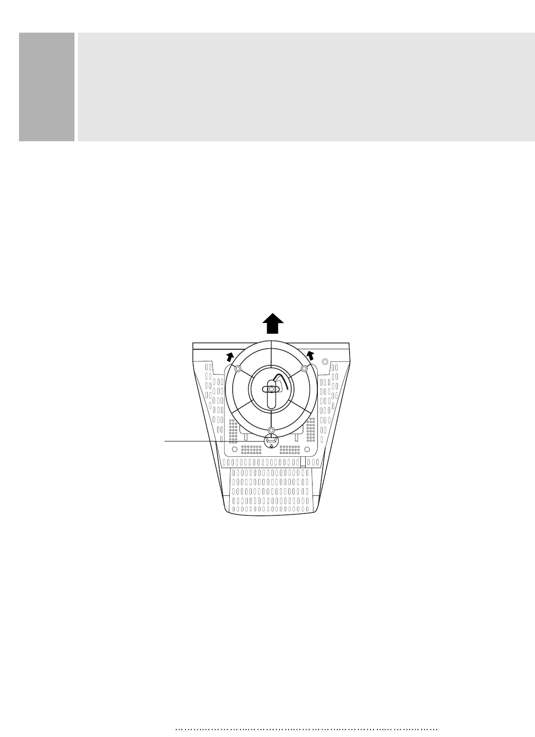
NO TOOLS ARE REQUIRED TO INSTALL THE MONITOR.
SIMPLY FOLLOW THE INSTRUCTIONS OUTLINED IN THE
FOLLOWING PAGE.
1. INSTALLING THE TILT/SWIVEL STAND
1) Align the stand with the front slots in the bottom of the monitor and insert the
Tilt/Swivel Stand into the slots.
2) Push the Tilt/Swivel Stand firmly toward the front of the monitor until the latches
click into the locked position.
2. CONNECT THE SIGNAL CABLE
1) Connect the end into the graphic card on back of the computer.
2) Secure the connection with the screws on the plug.
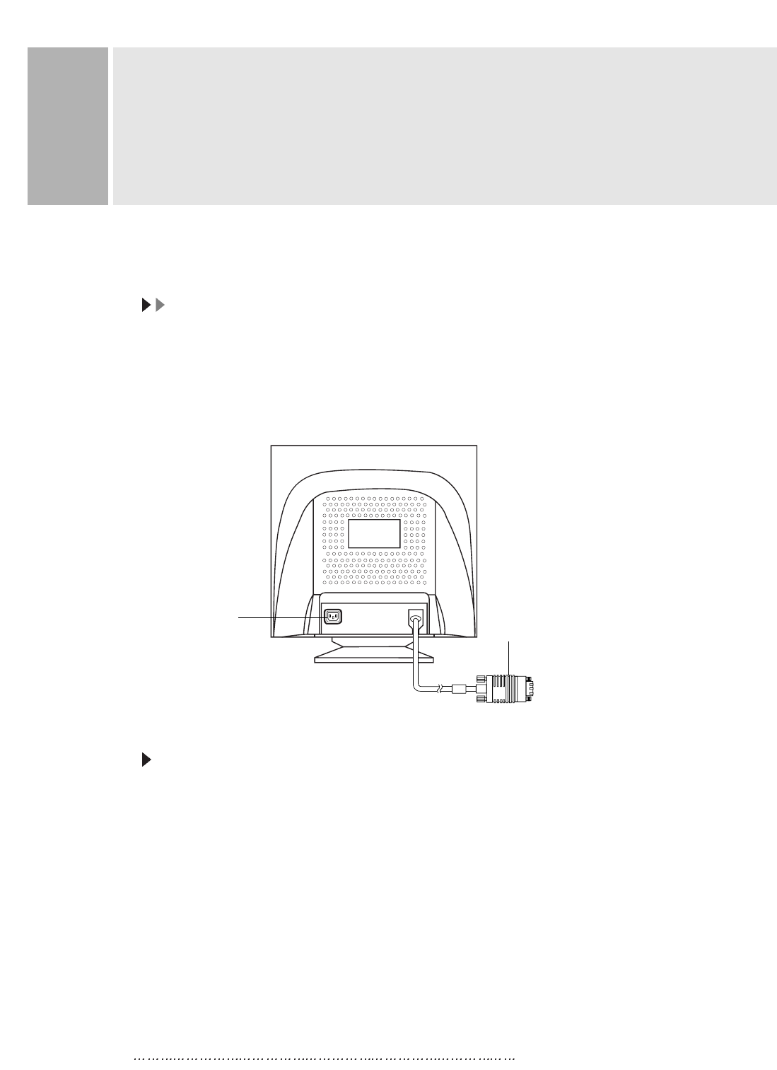
3. CONNECT THE POWER CORD
Connect the female end of the power cord to the power input
receptacle on the back panel of the monitor.
Then, plug the male end of the power cord to an AC outlet or computer.
4. TURN THIS MONITOR ON AND START YOUR SYSTEM
INSTRUCTION MANUAL 6
INSTALLATION
Hook
1
2
2
INSTRUCTION MANUAL 8
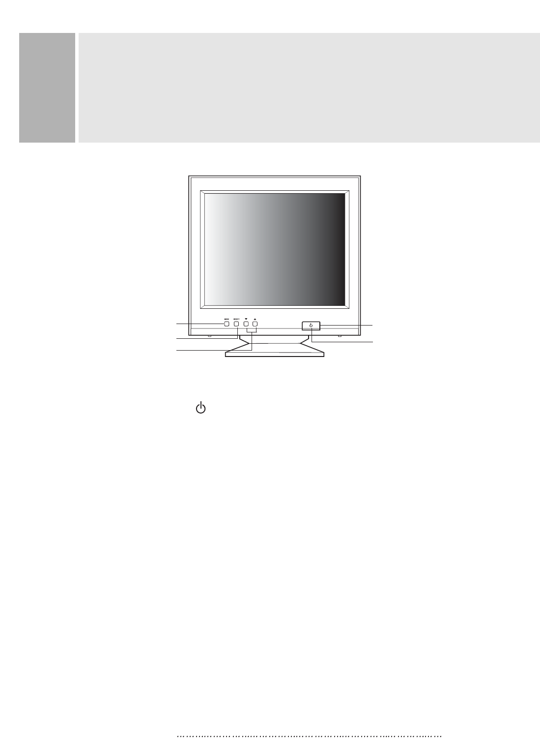
A. POWER ON/OFF( )
Turns the power ON or OFF. There will be a few seconds delay before
the display appears.
The power LED(next to the power switch) lights when the power
is turned ON.
The power is turned off by pressing the power switch again and
the power LED goes out.
B. MENU
Activates and exits the On Screen Display. This button can also be
used to move previous menu or status.
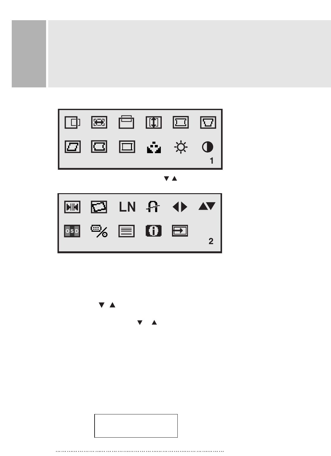
There are two OSD menu or status.
They are MAIN MENU1 (H.POSITION, H.SIZE, V.POSITION, V.SIZE,
PINCUSHION, TRAPEZOID, PARALLELOGRAM,
PINBALANCE, CORNER CORRECTION,
COLOR-TEMP, BRIGHTNESS, CONTRAST)
MAIN MENU2 (RECALL, ROTATION, LANGUAGE, DEGAUSS,
OSD H.POSITION, OSD V.POSITION, OSD ON TIME,
VIDEO LEVEL, MOIRE, INFORMATION, EXIT)
CONTROLS AND FUNCTIONS
B. MENU BUTTON
D. ADJUST BUTTONS
(DOWN & UP)
C. SELECT BUTTON POWER INDICATOR(LED)
A. POWER SWITCH
9 INSTRUCTION MANUAL
CONTROLS AND FUNCTIONS
C. SELECT
The select button allows user to activate the desired adjustment
with blinking icon.
D. ADJUST ( , )
The Adjust button allows user to choose the icons (controls) in the menu.
Pressing the adjust button or will step through all available
adjustment icons (controls).
In addition this adjust button can be used to adjust the icons (dot controls)
that is selected and activated (blinking) via the select button. When the adjust button
is pressed, The adjustment bar in the window will be increased or decreased.
After completing all the desired adjustments, the On Screen Display
will disappear with pressing the menu button.
1. SELF-TEST DISPLAY
When there is no connection, the On Screen Display
will show.
MAIN MENU 1 activates when you press the Menu button.
MAIN MENU 2 activates when you press () at the CONTRAST(EXIT) icon
in the menu1.
NO SIGNAL
CHECK SIGNAL CABLE
INSTRUCTION MANUAL 10
CONTROLS AND FUNCTIONS
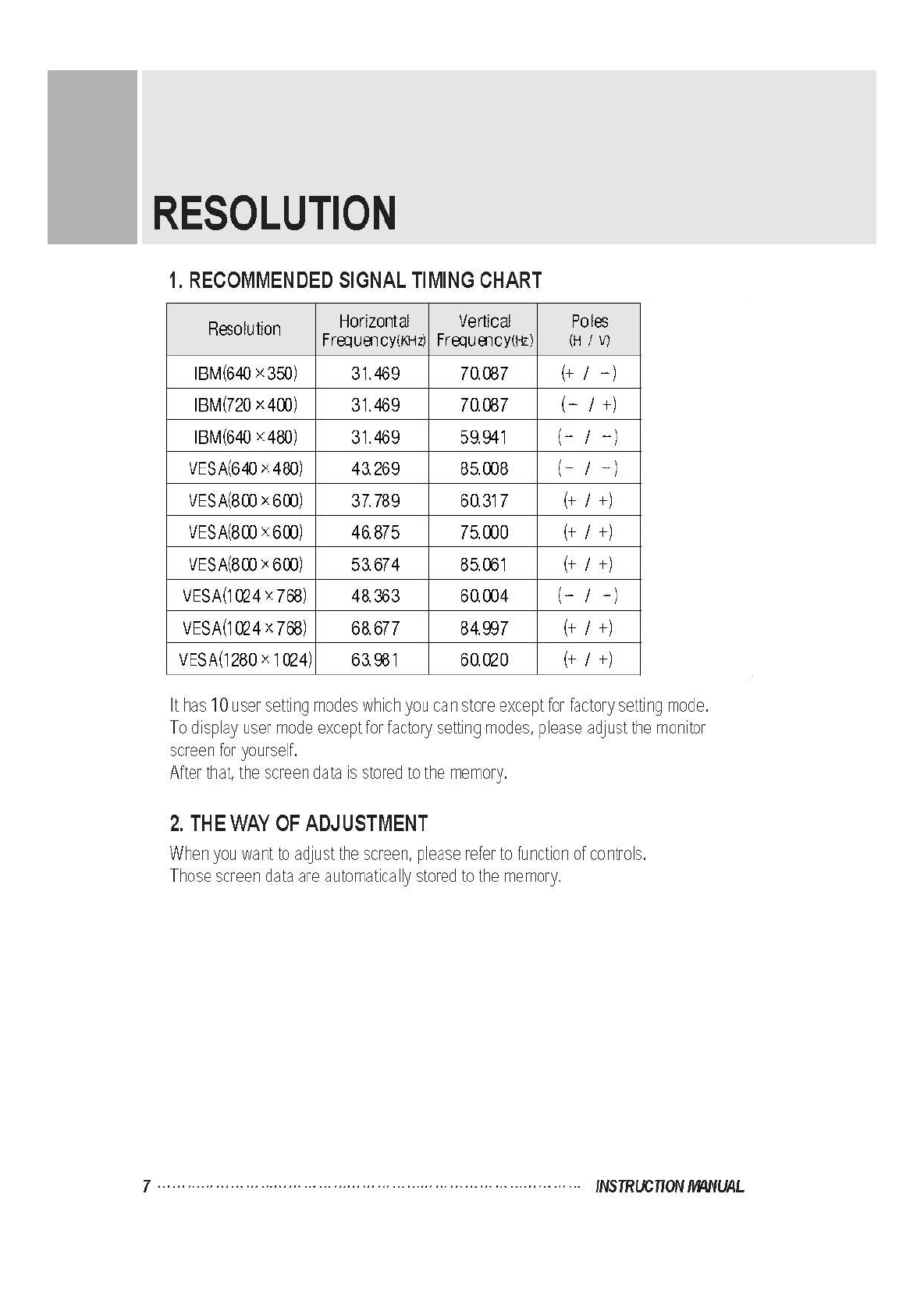
2. AUTO REGISTRATION
This monitor has 10 preset modes. If the current video is one of the
preset modes, the monitor keeps storing the custom display settings
into the permanent memory.
There are also 10 user modes that allow you to save the custom display
settings made to any video mode that is not one of the preset modes.
Adjustments are automatically registered without pressing any buttons.
Up to 10 user modes are stored automatically on a “First-In-First-Out”
basis.
3. OSD MENU DESCRIPTION
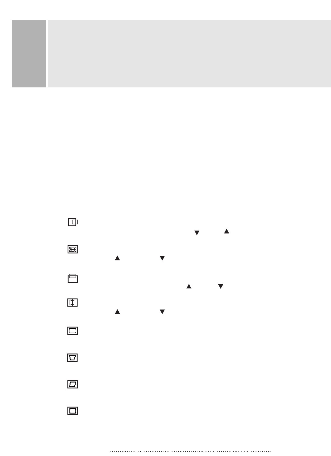
MAIN MENU 1
H. POSITION (Horizontal Position)
Moves images horizontally on screen left( ) or right( ).
H. SIZE (Horizontal Size)
Increases( ) or decreases( ) Size of image horizontally.
V. POSITION (Vertical Position)
Moves images vertically on screen up( ) or down( ).
V. SIZE (Vertical Size)
Increases( ) or decreases( ) Size of image vertically.
PINCUSHION
Adjusts the side Pincushion or barrelling.
TRAPEZOID
Adjusts the display sides to be parallel.
PARALLELOGRAM
Adjusts the tilt of the display sides.
PINBALANCE
Adjusts the curvature of the left and right sides of the screen image.
11 INSTRUCTION MANUAL
CONTROLS AND FUNCTIONS
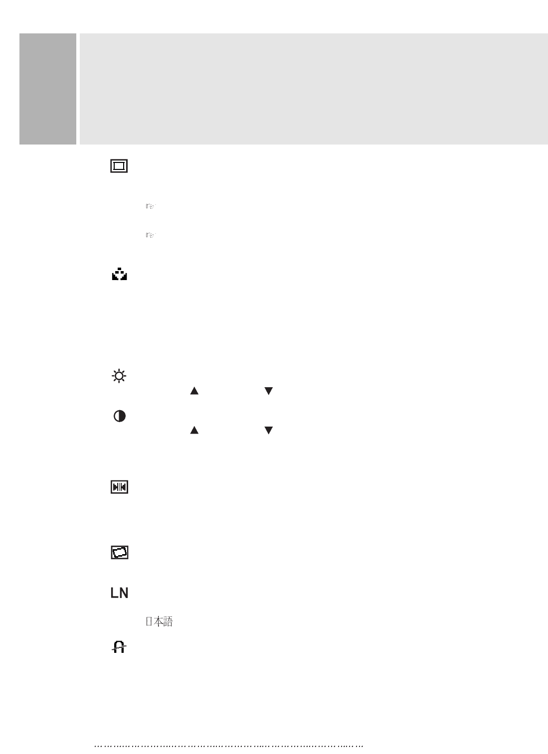
CORNER CORRECTION
User can select Top or Bottom Corner correction by pressing
the Select button.
TOP CORNER CORRECTION
Corrects the top corner image shape to a rectangle.
BOTTOM CORNER CORRECTION
Corrects the bottom corner image shape to a rectangle.
COLOR-TEMP
Adjusts color temperature to 9300K, 6500K(notes : 9300K is factory default).
Or, for a custom color mode, select “USER” and keep pressing select key
approximately 2 seconds to activate the RGB Sub-menu.
This adjust the intensity of the RGB video output. Using the select button
activate(blinking) the R-GAIN(Red Gain), G-GAIN(Green Gain) or
B-GAIN(Blue Gain) and change color strength for a customized color mode.
BRIGHTNESS
Increases( ) or decreases( ) the intensity(illumination) of the image.
CONTRAST
Increases( ) or decreases( ) the strength(lightness or dimness)
of the image.
MAIN MENU 2
RECALL
Resets the control functions back to the original factory preset values.
In order for the Recall function working, the timing must fall under one
of the factory preset timing modes.
ROTATION
Adjusts the tilt of image.
LANGUAGE
Selects a language among ENGLISH, DEUTSCH, FRANÇAIS, ESPAÑOL,
(JAPANESE).
DEGAUSS
Manually demagnetizes the CDT. This can be used if the display
becomes discolored.
Allow a minimum of 20 minutes to elapse between each degauss.
The monitor also will automatically degauss when power is applied,
and power saving mode is changed to normal mode.
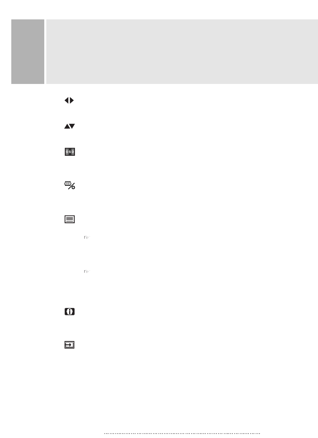
OSD H.POSITION
Moves the OSD position to left or right.
OSD V.POSITION
Moves the OSD position to up or down.
OSD ON TIME
If there isn’t key pressure OSD will be disappeared automatically
the setted seconds later.
VIDEO LEVEL
Selects the video level of the Video Graphic Card.
If the intensity of image is high select 1.0V & if low select 0.7V.
MOIRE
Adjusts the moire level of the screen.
H. MOIRE ADJUST
Reduces the optical effect of horizontal wavy lines on the display image.
These effects are usually more noticeable on large gray areas or on
black & white check board patterns.
V. MOIRE ADJUST
Reduces the optical effect of vertical wavy lines on the display image.
These effects are usually more noticeable on large gray areas or on
black & white check board patterns.
INFORMATION
Displays the current mode, horizontal frequency, vertical frequency,
the factory preset mode and user preset mode.
EXIT
Exit user menu.
INSTRUCTION MANUAL 12
CONTROLS AND FUNCTIONS
13 INSTRUCTION MANUAL
REAR VIEW
E. AC INLET
Power cord connection.
NNOOTTEE::
Power cord is used as main power disconnect device in this product.
F. D-SUB CONNECTOR OF SIGNAL CABLE
Connect to the analog RGB signal output connector of IBM PS/2, or compatible
computer.
ACCESSORY
1. POWER CORD
2. INSTRUCTION MANUAL
E. AC INLET F. D-SUB CONNECTOR
OF SIGNAL CABLE
SPECIFICATIONS
INSTRUCTION MANUAL 14
PICTURE TUBE
17 (16V) Flat CDT
Dot Type 0.25mm Pitch Black Matrix Screen High resolution screen
Dark Faceplate Glass High contrast screen
90 Deflection and 29.1mm Diameter Neck Lower power consumption
16 Visual Screen Diagonal Full-square type screen
Anti-Static Charge Face Electro static charge eliminated
Hi-view(Silica coat, Anti-Glare, Anti-Reflection) Surface Glare problem eliminated
Invar Shadow Mask.
INPUT SIGNAL
D-SUB INPUT
Analog RGB Video: 0.7Vpp / 75
Sync.: TTL Level
SWEEP FREQUENCY
Horizontal: 30-70KHz(Automatically)
Vertical: 50-150Hz(Automatically)
DISPLAY AREA(16 Viewable Size)
Full Size: 326 x 245mm
Preset Size: 305 x 225mm
POWER INPUT
AC 100-240V, 50/60Hz, 1.6-0.8A (FREE VOLTAGE)
POWER CONSUMPTION
85Watts(Max.)
Power Saving: Less than 5W
Dimensions (W x D x H)
399mm X 411mm X 394mm
WEIGHT
Net Weight : 16.0Kg
Gross Weight : 18.5Kg
RESOLUTION
1280 dots x 1024 lines(Max.)
DDC 1/2B
OSD(On Screen Display)
NNOOTTEE ::
Technical specifications are subject to change without notice.
15 INSTRUCTION MANUAL
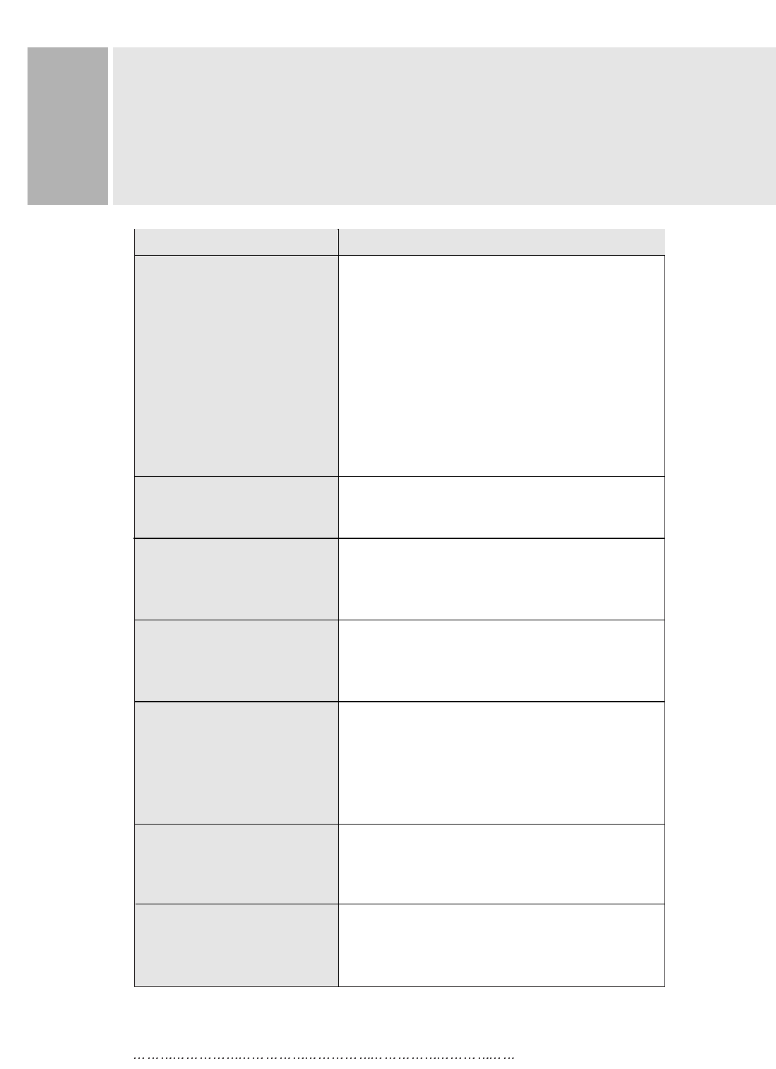
TROUBLE SHOOTING GUIDE
The video card should be completely
seated in its slot.
Power switch and computer power switch should
be in the ON position.
The signal cable should be completely connected
to the video card/computer.
Check connector for bent or pushed-in pins.
Power switch should be in the ON position and the
power cord should be connected.
Adjust size and position controls to adjust the
image.
Wait approximately ten seconds after making
adjustments before changing or disconnection the
signal or powering OFF the monitor.
Signal cable should be completely attached to the
computer.
Check the pin assignments and signal timmings of
the monitor and your video card.
Move electrical that may be causing electrical
interference away from the monitor.
Adjust the side pin-cushion control.
PROBLEM CHECK THESE ITEMS
No Picture
(Not in power saving mode)
LED on the monitor is not lit
Display image is not
centered, too small or
too large
Display size and position
were not saved
Image is scrolling or
unstable
Picture bounces or a wave
pattern is present in
the picture
Edges of the display image
are curved either inward
or outward