Orion Electric Co F9S946 19 Inch Color Display Monitor User Manual for F9S946 Color Display Monitor
Orion Electric Co Ltd 19 Inch Color Display Monitor Users Manual for F9S946 Color Display Monitor
Users Manual for F9S946 Color Display Monitor
MODEL No. : F9S946
1 INSTRUCTION MANUAL
CONTENTS
SAFETY INSTRUCTION 2
CAUTIONS 4
FCC RF INTERFERENCE STATEMENT 5
INSTALLATION 6
RESOLUTION 7
CONTROLS AND FUNCTIONS 8
REAR VIEW 13
POWER MANAGEMENT 14
SPECIFICATIONS 15
TROUBLE SHOOTING GUIDE 16
WICHTIGE HINWEISE (GERMAN) 17
This Monitor was
Manufactured by ISO 9001
Certified Factory

INSTRUCTION MANUAL 2
SAFETY INSTRUCTION
1. Read all of these instructions.
2. Save these instructions for later use.
3. Follow all warnings and instructions marked on the product.
4. Unplug this product from the wall outlet before cleaning.
Do not use liquid cleaners or aerosol cleaners. Use a dry cloth for cleaning.
5. Do not use this product near water.
6. Do not place this product on an unstable cart, stand or table.
The product may fall, causing serious damage to the product.
7. Slots and openings in the cabinet and the back or bottom are provided for
ventilation: to ensure reliable operation of the product and to protect it from
overheating these openings must not be blocked by placing the product on a bed,
sofa, rug or other similar surface. This product should never be placed near or over
a heat register.
This product should not be placed in a built-in installation unless proper ventilation
is provided.
8. This product should be operated from the type of power source indicated on the
marking label. If you are not sure of the type of power available consult your dealer
or local power company.
9. This product is equipped with a 3 wire grounding type plug having a third(grounding)
pin. This is a safety feature. If you are unable to insert the plug into the outlet,
contact your electrician to replace your obsolete outlet. Do not defeat the purpose of
the grounding-type plug.
10. Do not allow anything to rest on the power cord.
Do not locate this product where persons will walk on the cord.
11. If an extension cord is used with this product, make sure that the total of the
ampere ratings on the products plugged into the extension cord do not exceed the
extension cord ampere rating. Also, make sure that the total of all products
plugged into the wall outlet does not exceed 10 amperes.
12. Never push objects of any kind into this product through cabinet slots as they may
touch dangerous voltage points or short out parts that could result in a risk of fire
or electric shock. Never spill any kind of liquid on the product.
3 INSTRUCTION MANUAL
SAFETY INSTRUCTION
13. Do not attempt to service this product yourself, as opening or removing covers
may expose you to dangerous voltage points or other risks.
Refer all servicing to service personnel.
14. Unplug this product from the wall outlet and refer servicing to qualified service
personnel under the following conditions.
A. When the power cord or plug is damaged or frayed.
B. If liquid has been spilled into the product.
C. If the product has been exposed to rain or water.
D. If the Product does not operate normally when the operating instructions are
followed. Adjust only those controls that are covered by the operating
instructions since improper adjustment of other controls may result in damage
and will often require extensive work by a qualified technician to restore normal
operation.
E. If the product has been dropped or the cabinet has been damaged.
F. If the product exhibits a distinct change in performance, indicating a need for
service.
CC
CCAA
AAUU
UUTT
TTII
IIOO
OONN
NN
The power supply cord is used as the main disconnect device, ensure that the
socket-outlet is located/installed near the equipment and is easily accessible.
AA
AATT
TTTT
TTEE
EENN
NNTT
TTII
IIOO
OONN
NN
Le cordon d`alimentation est utillsé comme interrupteur général. La prise de
courant doit être située ou installée à proximité du matériel et être facile
d`accès
CAUTION TO SERVICE PERSONNEL
POWER SUPPLY CORD IS USED AS MAIN POWER DISCONNECT DEVICE IN
THIS PRODUCT. UNPLUG THIS PRODUCT FROM THE WALL OUTLET
BEFORE REMOVING THE BACK COVER AND SERVICING
EMISSION CHARACTERISTICS TESTED BY SEMKO
THIS PRODUCT HAS BEEN TESTED AND HAS SHOWN COMPLIANCE WITH
THE NATIONAL SPECIFICATIONS SUCH AS SWEDISH MPR 1990.10.(MPR )
INSTRUCTION MANUAL 4
CAUTIONS
NEVER REMOVE THE BACK COVER
NEVER REMOVE THE BACK COVER
Removal of the back cover should be carried out only by qualified personnel.
This display monitor contains high voltage inside.
DO NOT USE IN HOSTILE ENVIRONMENTS
DO NOT USE IN HOSTILE ENVIRONMENTS
To prevent shock or fire hazard. Do not expose the unit to rain or moisture.
This unit is designed to be used in the office or home. Do not subject the unit to
vibrations, dust of corrosive gases.
KEEP IN A WELL VENTILATED PLACE
KEEP IN A WELL VENTILATED PLACE
Ventilation holes are provided on the cabinet to prevent the temperature from
rising.
Do not cover the unit or place anything on the top of unit. Ventilation holes are
provided also on the bottom of the cabinet.
AVOID HEAT
AVOID HEAT
Avoid placing the unit in direct sunshine or near a heating appliance.
BE CAREFUL OF MAGNETIC FIELDS
BE CAREFUL OF MAGNETIC FIELDS
Do not place a magnet, speaker system, floppy disc drive or anything which will
generate magnetism near the unit, A magnetic field may cause blurred colors or
distortion of the displayed pattern.
TO ELIMINATE EYE FATIGUE
TO ELIMINATE EYE FATIGUE
Do not use the unit against a bright back ground and where sunlight or other light
sources will shine directly on the monitor.
BE CAREFUL OF HEAVY OBJECT
BE CAREFUL OF HEAVY OBJECT
Neither the monitor itself nor any other heavy object should rest on the power cord.
Damage to a power cord can cause fire or electrical shock.
5 INSTRUCTION MANUAL
FCC RF
INTERFERENCE STATEMENT
NN
NNOO
OOTT
TTEE
EE
::
::
This equipment has been tested and found to comply with the limits for a
Class B digital device, pursuant to Part 15 of the FCC Rules. These limits are
designed to provide reasonable protection against harmful interference in a
residential installation.
This equipment generates, uses and can radiate radio frequency energy and,
if not installed and used in accordance with the instructions, may cause
harmful interference to radio communications. However, there is no guarantee
that interference will not occur in a particular installation.
If this equipment does cause harmful interference to radio or television
reception which can be determined by turning the equipment off and on, the user
is encouraged to try to correct the interference by one or more of the following
measures.
- Reorient or relocate the receiving antenna.
- Increase the separation between the equipment and receiver.
- Connect the equipment into an outlet on a circuit different from that to which
the receiver is connected.
- Consult the dealer or an experienced radio, TV technician for help.
- Only shielded interface cable should be used.
Finally, any changes or modifications to the equipment by the user not
expressly approved by the grantee or manufacturer could void the users
authority to operate such equipment.
DOC COMPLIANCE NOTICE
This digital apparatus does not exceed the Class B limits for radio noise emissions
from digital apparatus set out in the radio interference regulation of Canadian
Department of Communications.
AVIS DE CONFORMATION AU MDC(DOC)
Le présent appareil numérique n´émet pas de bruits radio-électriques dépassant les
limites appliqués aux appareils numériques de Class B d´après les règlements sur
le brouillage radio-électrique conçuent par le ministère des communications du
Canada.

INSTRUCTION MANUAL 6
INSTALLATION
NO TOOLS ARE REQUIRED TO INSTALL THE MONITOR.
SIMPLY FOLLOW THE INSTRUCTIONS OUTLINED IN THE
NEXT FEW PAGES.
1. CONNECT THE SIGNAL CABLE
A. ATTACHED SIGNAL CABLE
1) If the signal cable is attached on the monitor, connect the other and
into the graphic card on back of the computer.
2) Secure the connection with the screws on the plug.
B. DETACHED SIGNAL CABLE
1) Connect one end of the signal cable to the back panel of the monitor
and connect the other end to the graphic card on back of the computer.
2) Secure the connection with the screws on the plug.
2. CONNECT THE POWER CORD
Connect the female end of the power cord to the power input
receptacle on the back panel of the monitor.
Then, plug the male end of the power cord to an AC outlet or computer.
3. TILT/SWIVEL STAND
The Tilt/Swivel Stand is installed already, when this monitor set manufactured.
4. MAKING THE RIGHT CONNECTIONS
1) Make sure the power to this monitor and the computer system is
turned OFF.
2) Connect the D-SUB connector of signal cable to system.
3) Connect one end of the power cord to this monitor and the other
end to the wall or P/C outlet.
4) Turn this monitor ON.
5) Start your system.
7 INSTRUCTION MANUAL
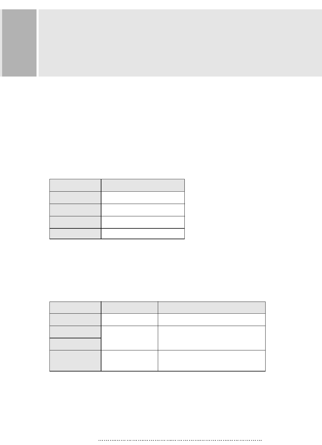
RESOLUTION
This monitor is a digitally-controlled multi-frequency monitor.
It operates at horizontal frequencies of 30 to 96KHz and vertical
frequencies of 50 to 160Hz.
Because of its micro processor-based designs it offers auto-synchronization
and auto-sizing capabilities. This monitor offers 12 programmed settings
as listed in the table below.
These 12 preset modes cover most of the common video modes supported by
popular graphic adaptors. However, each adaptors implementation of these
video modes may vary slightly in timings. You may find it necessary to make
minor adjustments to the display settings (i.e., horizontal position) using
the On Screen Display. For further information and instructions on using
the On Screen Display, please refer to Section 5. “Controls and Functions.”
You can also program any signal within its frequency range of 30-96KHz
horizontal and 50-160Hz vertical as user Programmed modes.
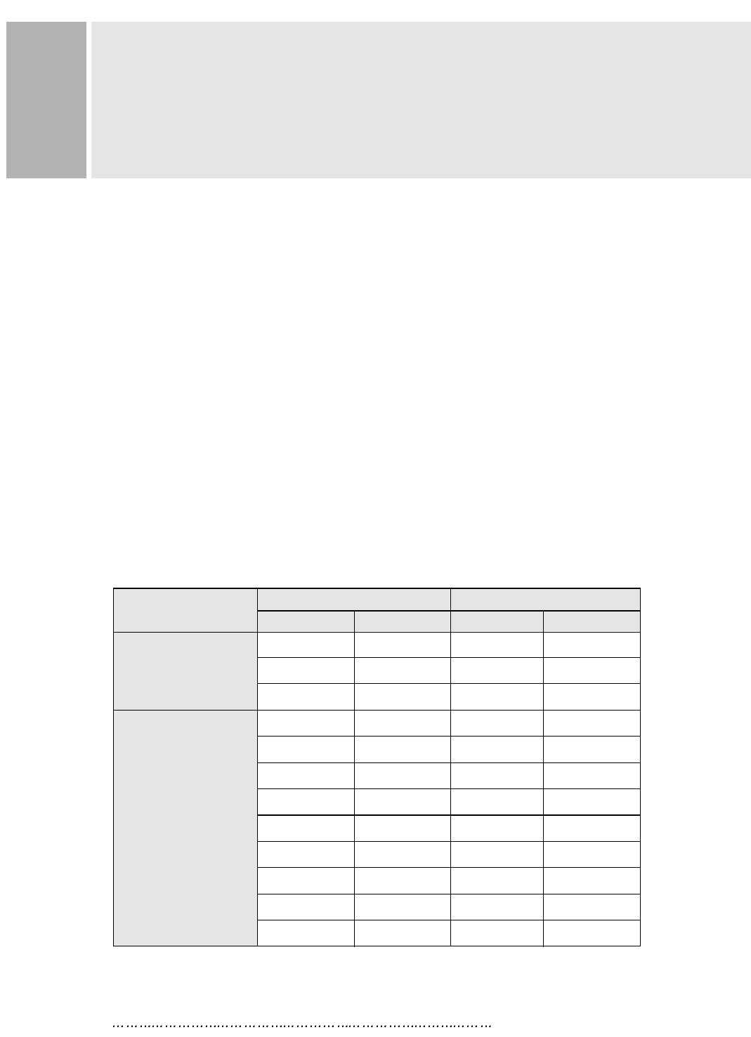
PRESET MODES
VGA
VESA
RESOLUTION FREQUENCY
H(Pixels) V(Lines) H(KHz) V(Hz)
640 350 31.5 70
720 400 31.5 70
640 480 31.5 60
640 480 43.2 85
800 600 46.9 75
800 600 53.6 85
1024 768 68.7 85
1152 864 67.5 75
1280 1024 64.0 60
1280 1024 80.0 75
1600 1200 81.3 65
1600 1200 93.7 75
INSTRUCTION MANUAL 8
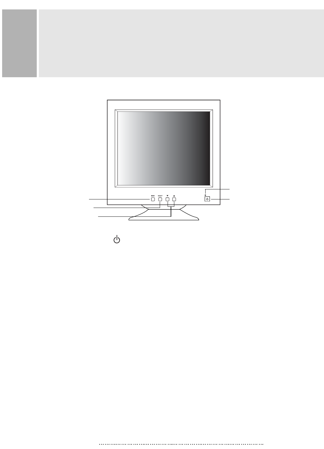
A. POWER ON/OFF( )
Turns the power ON or OFF. There will be a few seconds delay before
the display appears.
The power LED(next to the power switch) lights when the power
is turned ON.
The power is turned off by pressing the power switch again and
the power LED goes out.
B. MENU
Activates and exits the On Screen Display. This button can also be
used to move previous menu or status.
There are two OSD menu or status.
They are USER MENU 1 (H POSITION, H SIZE, V POSITION, V SIZE,
PIN CUSHION, TRAPEZOID, CORNER CORECTION, PARALLELOGRAM,
PIN BALANCE, TILT, RECALL, COLOR TEMP, BRIGHTNESS, CONTRAST)
& USER MENU 2 (INFORMATION, LANGUAGE, MOIRE, DEGAUSS,
OSD HORIZONTAL, OSD VERTICAL, OSD ON TIME).
CONTROLS AND FUNCTIONS
B.MENU BUTTON
POWER INDICATOR(LED)
A. POWER SWITCH
D. ADJUST BUTTONS
(DOWN & UP)
C.SELECT BUTTON
9 INSTRUCTION MANUAL
CONTROLS AND FUNCTIONS
C. SELECT
The select button allows user to activate the desired adjustment
with blinking icon.
D. ADJUST ( )
The Adjust button allows user to choose the icons (controls) in the menu.
Pressing the adjust button or will step through all available
adjustment icons (controls).
In addition this adjust button can be used to adjust the icons (controls)
that is selected and activated (blinking) via the select button.
Press the Adjust button.
A window containing an adjustment bar will increase or decrease.
After completing all the desired adjustments, the On Screen Display
will disappear with pressing the menu button.
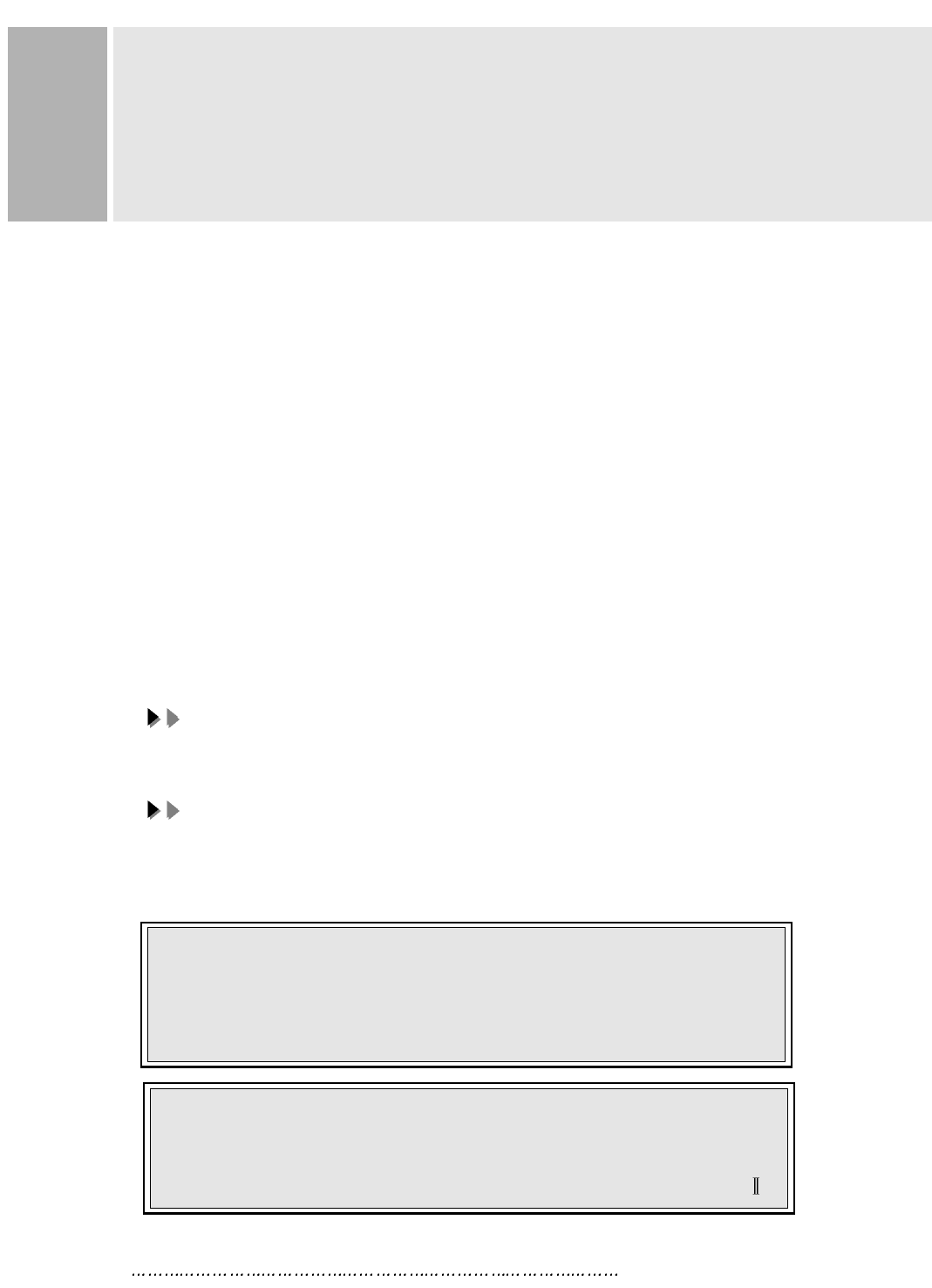
1. SELF-TEST DISPLAY
When there is no signal input (No connection), the On Screen Display
will show.
USER MENU 1 activates when you press the Menu button.
USER MENU 1 activates when you press the Menu button.
USER MENU 2 activates via the adjust (
USER MENU 2 activates via the adjust ( /
/ ) button.
) button.
NO SIGNAL
CHECK SIGNAL CABLE
INSTRUCTION MANUAL 10
CONTROLS AND FUNCTIONS
2. AUTO REGISTRATION
This monitor has 12 preset modes. If the current video is one of the preset modes,
the monitor keeps storing the custom display settings into the permanent memory.
There are also 10 user modes that allow you to save the custom display settings
made to any video mode that is not one of the preset modes.
Adjustments are automatically registered without pressing any buttons.
Up to 10 user modes are stored automatically on a “First-In-First-Out” basis.
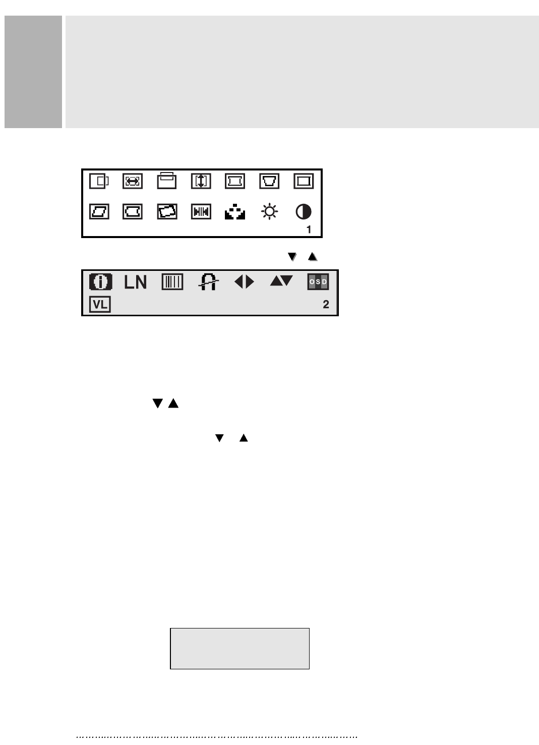
3. OSD MENU DESCRIPTION
USER MENU 1
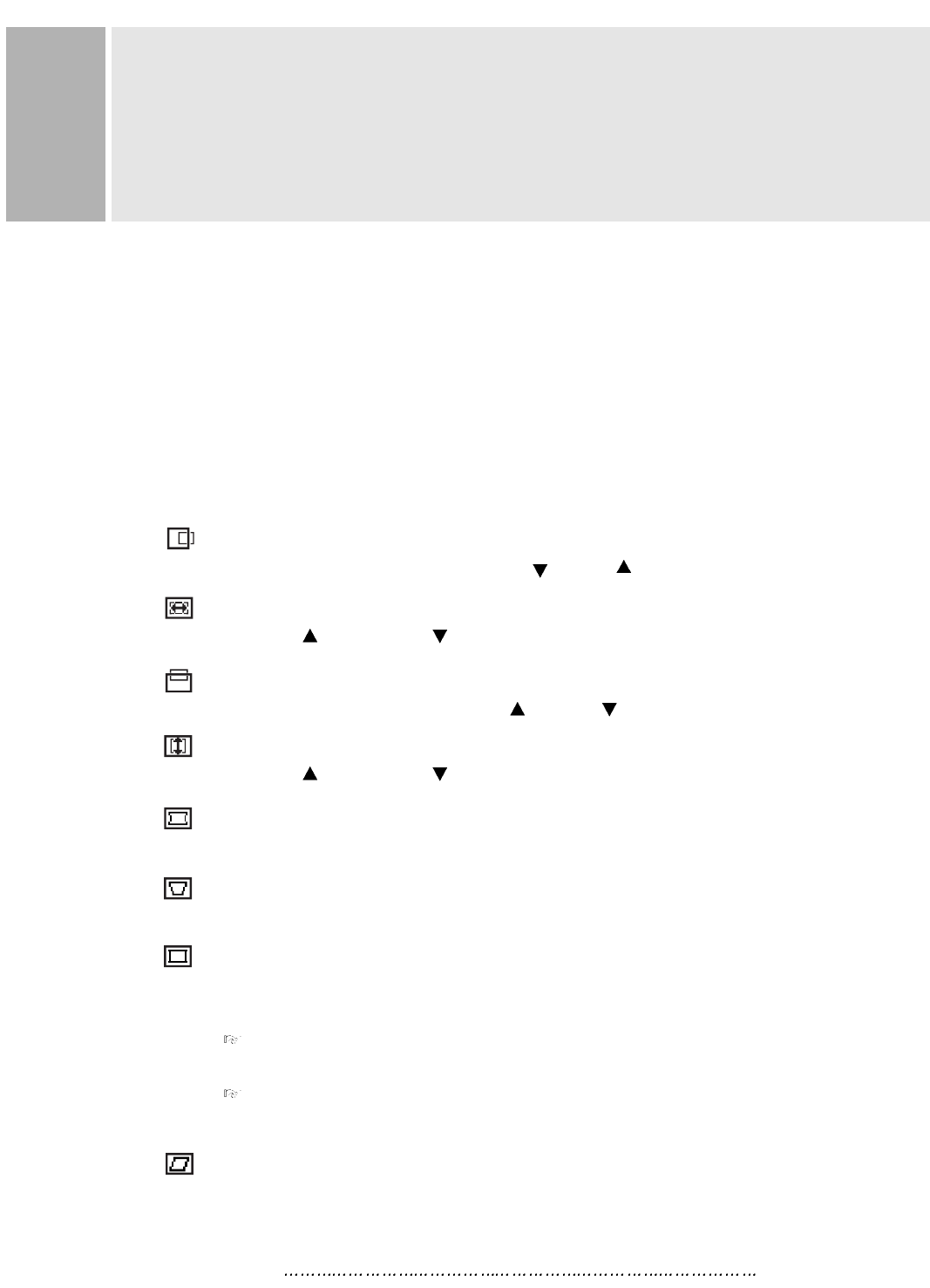
H POSITION (Horizontal Position)
Moves images horizontally on screen left( ) or right( ).
H SIZE (Horizontal SIze)
Increases( ) or decreases( ) Size of image horizontally.
V POSITION (Vertical position)
Moves images vertically on screen up( ) or down( ).
V SIZE (Vertical SIze)
Increases( ) or decreases( ) Size of image vertically.
PINCUSHION
Adjusts the side Pin-cushion or barrelling.
TRAPEZOID
Adjusts the display sides to be parallel.
CORNER CORRECTION
User can select Top or Bottom Corner correction by pressing
the Select button and also can activate with select button.
TOP CORNER CORRECTION
Corrects the top corner image shape to a rectangle.
BOTTOM CORNER CORRECTION
Corrects the bottom corner image shape to a rectangle.
PARALLELOGRAM
Adjusts the tilt of the display sides.
11 INSTRUCTION MANUAL
CONTROLS AND FUNCTIONS
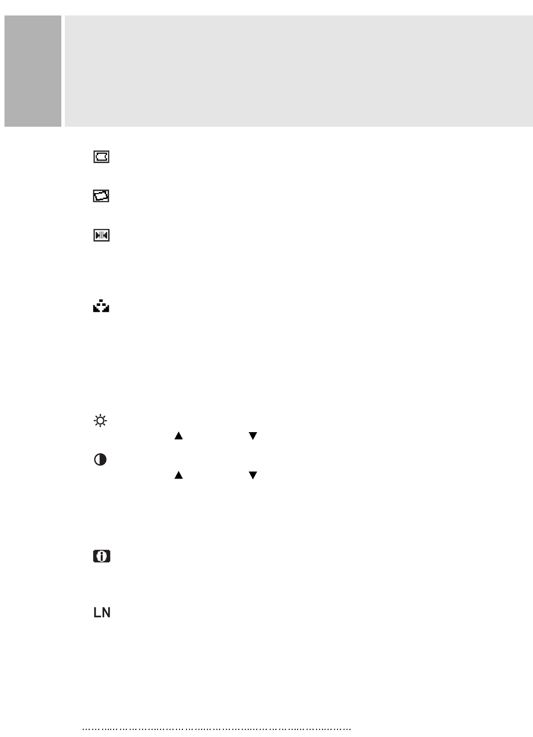
PIN BALANCE
Adjusts the curvature of the left and right sides of the screen image.
TILT
Adjusts the tilt of image.
RECALL
Resets the control functions back to the original factory preset values.
In order for the Recall function working, the timing must fall under one of the
factory preset timing modes.
COLOR TEMPERATURE
Adjusts color temperature to 9300K, 6500K(notes : 9300K is factory default).
Or, for a custom color mode, select “USER” and push the select button to
activate the RGB Sub-menu.
This adjust the intensity of the RGB video output. Using the select button
activate the RG(Red Gain), GG(Green Gain) or BG(Blue Gain) and change
color strength for a customized color mode.
BRIGHTNESS
Increases( ) or decreases( ) the intensity(illumination) of the image.
CONTRAST
Increases( ) or decreases( ) the strength(lightness or dimness) of the
image.
USER MENU 2
INFORMATION
Displays horizontal frequency(on violet) and vertical frequency(on violet) and
“PRESET MODE” means the factory preset mode(on violet).
LANGUAGE
Selects a language among ENGLISH, DEUTSCH, FRANÇAIS, ESPAÑOL,
ITALIANO.
INSTRUCTION MANUAL 12
CONTROLS AND FUNCTIONS
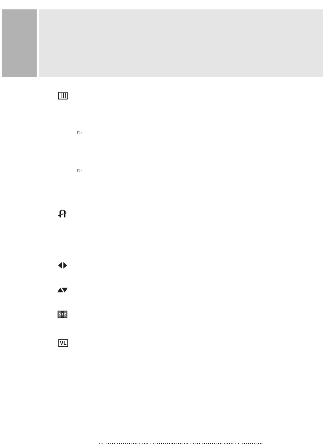
MOIRE
Adjusts the moire level of the screen.
Activate MOIRE icon & keep pressing select button approximately
2 seconds after select “ON”.
H. MOIRE ADJUST
Reduces the optical effect of horizontal wavy lines on the display image.
These effects are usually more noticeable on large gray areas or on
black & white check board patterns.
V. MOIRE ADJUST
Reduces the optical effect of vertical wavy lines on the display image.
These effects are usually more noticeable on large gray areas or on
black & white check board patterns.
DEGAUSS
Manually demagnetizes the CDT. This can be used if the display becomes
discolored.
Allow a minimum of 20 minutes to elapse between each degauss.
The monitor also will automatically degauss when power is applied.
OSD HORIZONTAL
Moves the OSD position to left or right.
OSD VERTICAL
Moves the OSD position to up or down
OSD ON TIME
Adjusts on screen OSD running time.
VIDEO LEVEL
Selects the video level of the Video Graphic Card.
If the intensity of image is high select 1.0V & if low select 0.7V.
13 INSTRUCTION MANUAL
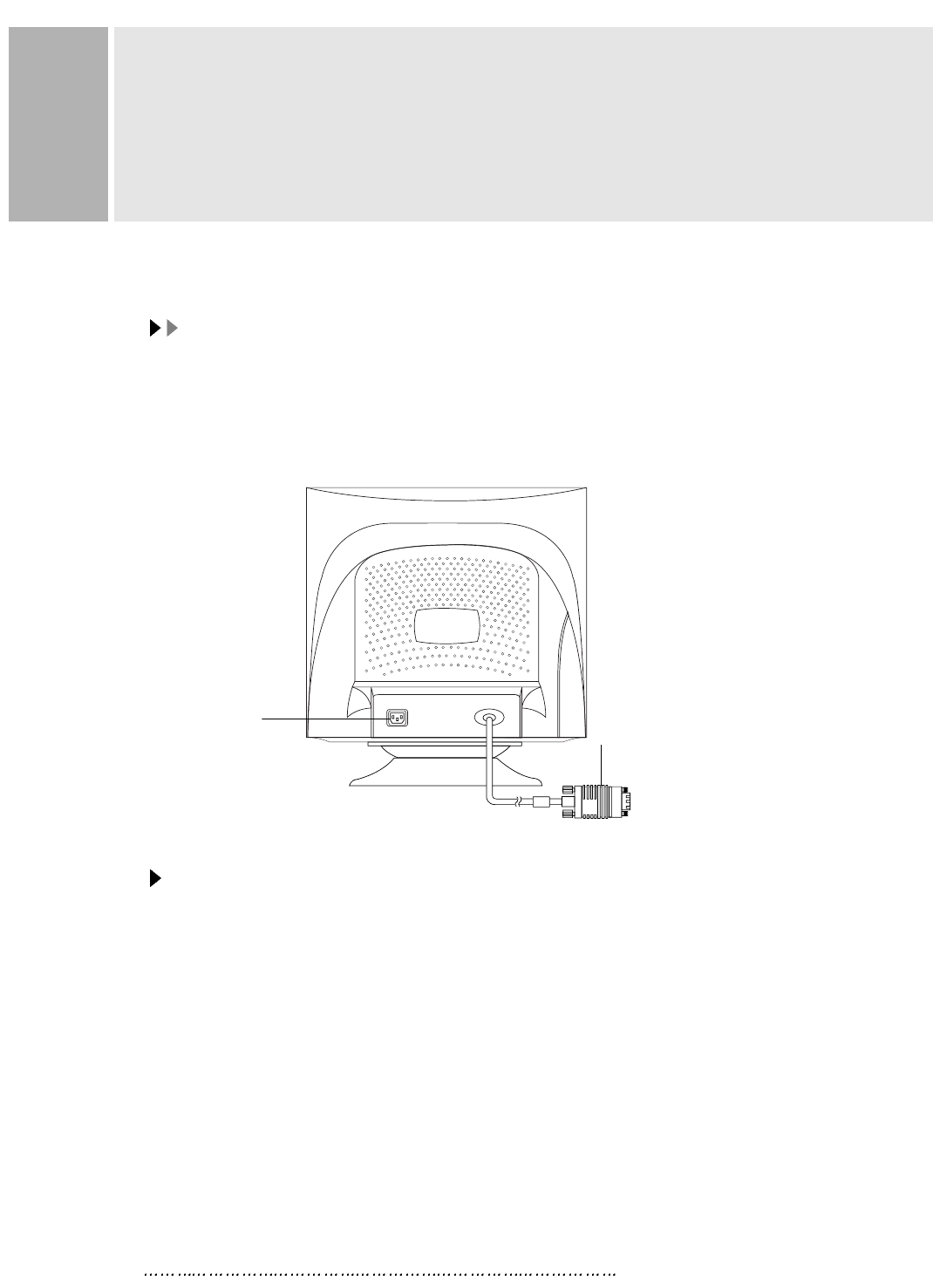
REAR VIEW
E. AC INLET
Power cord connection.
NNOOTTEESS
Power cord is used as main power disconnect device in this product.
F. D-SUB CONNECTOR OF SIGNAL CABLE
Connect to the analog RGB signal output connector of video card.
ACCESSORY
1. POWER CORD
2. INSTRUCTION MANUAL
3. SIGNAL CABLE(if detachable type)
E. AC INLET F. D-SUB CONNECTOR
OF SIGNAL CABLE
INSTRUCTION MANUAL 14
This monitor features a power management system to “power down” upon receipt of the
VESA DPMS(The display power management signaling) from a VESA DPMS video
card.
The VESA DPMS-compliant video card performs this signaling system through not
sending horizontal, vertical, or sync signal.
This monitor enters an appropriate mode through identifying each of the three modes
of the signaling system.
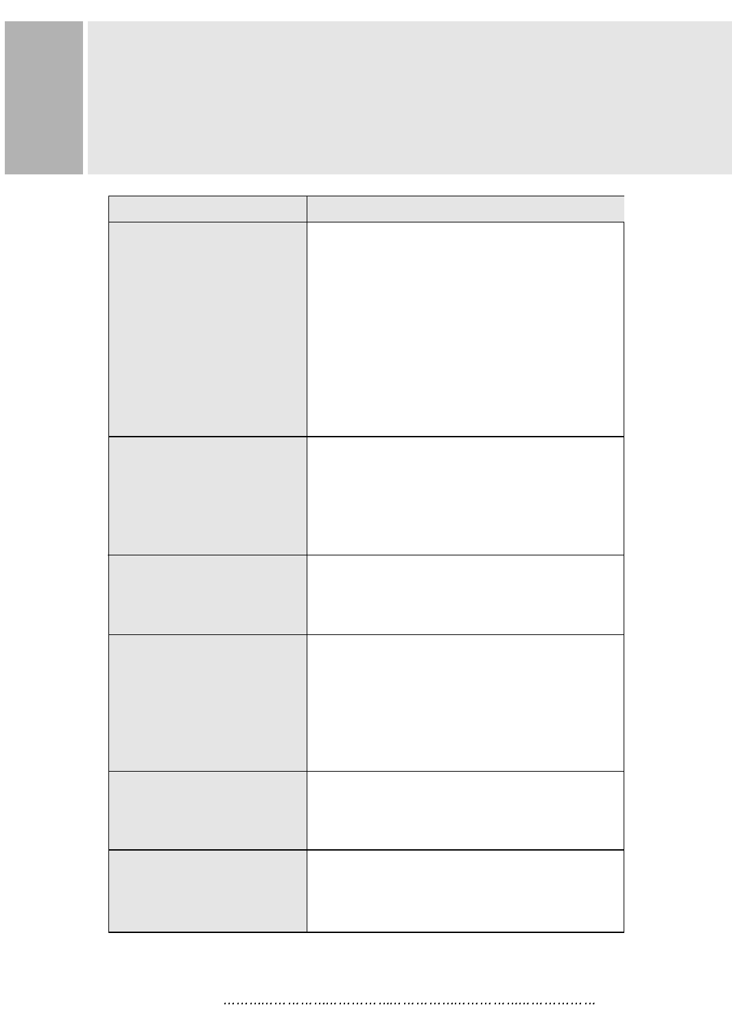
POWER CONSUMPTION
LED INDICATOR
The power management feature of the monitor is comprised of four
stages : On(Green), Standby, Suspend(Amber blinking) and Active
off(Amber).
POWER MANAGEMENT
POWER CONSUMPTION
< 100W
< 15W
< 15W
< 5W
MODE
ON
STANDBY
SUSPEND
ACTIVE OFF
LED COLOR
GREEN
AMBER BLINKING
AMBER
MODE
ON
STANDBY
SUSPEND
ACTIVE OFF
MONITOR OPERATION
Normal Operation
Screen blanks after preset idle time
and Some electronic circuits go off.
All circuitry in the monitor is shout down
except for a low power detection circuit.

15 INSTRUCTION MANUAL
SPECIFICATIONS
CDT
CDT
19 (18 Viewable) Flat CDT Dynamic focus, Invar shadow mask and
ARAS(Anti-Reflection Anti-Static) Coating.
0.25mm Dot Pitch
RESOLUTION(H x V)
RESOLUTION(H x V)
1600x1200 Non Interlaced
FREQUENCY
FREQUENCY
HORIZONTAL : 30-96KHz
VERTICAL : 50-160Hz
VIDEO DOT RATE
VIDEO DOT RATE
150MHz
INPUT SIGNAL
INPUT SIGNAL
VIDEO(Analog 0.7Vp-p/75 )
SYNC(Separate and Composite TTL Level)
ACTIVE DISPLAY AREA (W x H)
ACTIVE DISPLAY AREA (W x H)
Preset : 346mm X 255mm
Full : 366mm X 275mm
DIMENSIONS (W x D x H)
DIMENSIONS (W x D x H)
625mm X 570mm X 573mm(Carton Box)
WEIGHT
WEIGHT
Net Weight : 23.5Kg
Gross Weight : 26.5Kg
POWER SUPPLY
POWER SUPPLY
AC 100-240V, 50/60Hz(FREE VOLTAGE)
AC 220-240V, 50Hz(OPTIONAL)
NNOOTTEE ::
Technical specifications are subject to change without notice.
TROUBLE SHOOTING GUIDE
1. Check that power cord of the Monitor have
been connected securely into wall outlet
or grounded extension cable or strip.
2. Powerf switch should be in the ON position
and LED is lit.
3. Check that the Brightness and/or the Contract
adjustments of the Display have not been
turned down to minimum levels.
1. The signal cable should be completely
connected to the video card/computer.
2. The video card should be completely seated in
its slot and the computer is switched ON.
Adjust size and position in the OSD, your settings
will be memorized automatically in microprocessor
of the monitor.
The sound you hear indicates that the demagnet-
izing circuit is activated.
Every time the monitor is powered on, it will go
through the degaussing process which helps
eliminate any purity problems.
Remove electric equipments that may be causing
electric intereference to the monitor.
This usually occurs if on extension signal cable
is installed or the signal cable is not
fastened to the back of the video card.
TROUBLE TROUBLE SHOOTING TIP
No image on display screen
“No signal, Check signal
Cable” message on screen
Display image is not
centered, too small or
too large
“Humming” sound when
switch on the monitor
Picture bounces or a
wave pattern is present in
the picture
There appears to be a
second image or “ghost” on
the screen
INSTRUCTION MANUAL 16
Achten Sie darauf, da das Gerät nur in eine 240V(220V) Schuko-
Steckdose eingesteckt wird.
Die Steckdose sollte jederzeit frei zugänglich sein, um bei einem evtl.
auftretenden Notfall das Gerät schnell von der Stromversorgung zu trennen.
Achten Sie desweiteren darauf, da die Netzanschlu leitung nicht
mechanisch beansprucht noch sonstwie beschädigt wird.
Öffnen Sie niemals das Gerät! Im Inneren befinden sich Teile mit
gefährlicher Spannung.
Bevor Sie das Gerät reinigen, ziehen Sie bitte den Netzstecker aus der
Steckdose. Säubern Sie das Gerät dann mit einem feuchten (keinesfalls
tropfnassen) Lappen.
Das Gerät ist funkentstört nach EN55022
Bauartzulassung:
Die in diesem Gerät entstehende Röntgenstrahlung ist ausreichend
abgeschirmt (Ortsdosis in 0.1m Abstand weniger als 1.0 /h).
Die Beschleunigungsspannung beträgt maximal 28KV.
Stellen Sie das Gerät an einem ergonomisch günstigen Ort auf und sorgen
Sie dafür, da der Betrieb des Monitors mit nach ISO9241-3.7.8
geprüfter Peripherie sichergestellt ist.
Maschinenlärminformationsverordnung 3. GSGV, 18.01.91 : Der
arbeitsplatzbezogene Schalldruckpegel beträgt 70dB(A) oder weniger
gemä ISO 7779.
Falls SIe dennoch Fragen haben, auf die die Bedienungsanleitung keine
Antwork geben kann, so kontaktieren Sie bitte den nächsten Fachhändler.
FOR GERMAN
WICHTIGE HINWEISE
17 INSTRUCTION MANUAL