Orolia 82-501 User Manual McM G4
Orolia Ltd McM G4
UserManual.wiki
>
Orolia
>
82-501 User Manual
>
McM G4 User manual
Contents
1.
McM G4 User manual
2.
Pains Wessex SOS Precision User Manual
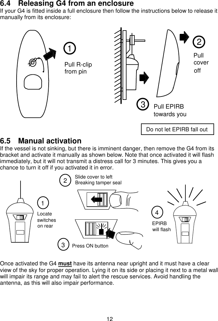
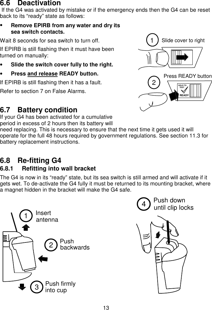
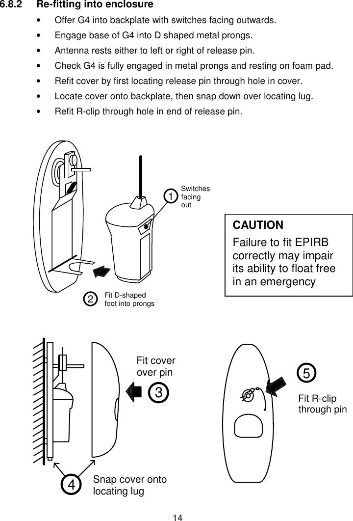
McM G4 User manual
Navigation menu
Upload a User Manual
Namespaces
Wiki Guide
HTML
PDF
Info
Views
User Manual
Discussion / Help
Navigation